EMS-1221 - Ryobi
EMS-1221 - Ryobi
EMS-1221 - Ryobi

Create successful ePaper yourself
Turn your PDF publications into a flip-book with our unique Google optimized e-Paper software.
<strong>EMS</strong>-<strong>1221</strong> manual 13/11/03 14:27 Page A1<br />
<strong>EMS</strong>-<strong>1221</strong><br />
F<br />
GB<br />
D<br />
E<br />
I<br />
P<br />
NL<br />
S<br />
DK<br />
N<br />
FIN<br />
GR<br />
HU<br />
CZ<br />
RU<br />
RO<br />
PL<br />
®<br />
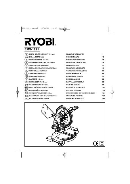
SCIE À COUPE D'ONGLET 210 mm MANUEL D’UTILISATION 1<br />
210 mm MITRE SAW USER’S MANUAL 10<br />
GEHRUNGSSÄGE 210 mm BEDIENUNGSANLEITUNG 18<br />
SIERRA INGLETADORA DE 210 mm MANUAL DE UTILIZACIÓN 28<br />
TRONCATRICE DA 210 mm MANUALE D’USO 37<br />
SERRA CIRCULAR ANGULAR 210 mm MANUAL DE UTILIZAÇÃO 46<br />
VERSTEKZAAG 210 mm GEBRUIKERSHANDLEIDING 55<br />
210 mm GERINGSSÅG INSTRUKTIONSBOK 64<br />
210 mm GERINGSSAV BRUGERVEJLEDNING 72<br />
GJÆRSAG 210 mm BRUKSANVISNING 80<br />
KULMAUSSAHA 210 mm KÄYTTÄJÄN KÄSIKIRJA 88<br />
ΦΑΛΤΣΠΡΙΝ 210 mm ∆ΗΓΙΕΣ ΡΗΣΗΣ 96<br />
GÉRVÁGÓ FŰRÉSZGÉP, 210 mm HASZNÁLATI ÚTMUTATÓ 107<br />
POKOSOVÁ PILA 210 mm NÁVOD K OBSLUZE 116<br />
íéêñéÇéóçÄü èàãÄ 210 ÏÏ êìäéÇéÑëíÇé èé ùäëèãìÄíÄñàà 125<br />
FERĂSTRĂU DE TĂIAT ÎN UNGHI 210 mm MANUAL DE UTILIZARE 133<br />
PILARKA UKOŚNA 210 mm INSTRUKCJA OBSŁUGI 142<br />
RR OO TT AA TT II OO NN<br />
44 55<br />
31.62 31.62 31.62 31.62<br />
3 3 3 3 00<br />
00<br />
22.5 22.5 22.5 22.5<br />
15 15 15 15<br />
45 45<br />
31.62 31.62<br />
30 30<br />
22.5 22.5<br />
15 15
<strong>EMS</strong>-<strong>1221</strong> manual 13/11/03 14:27 Page A2<br />
4<br />
26<br />
31<br />
11<br />
27<br />
17<br />
OO TT AA RR TT II OO NN<br />
30<br />
44 55<br />
9<br />
31.62 31.62 31.62 31.62<br />
1<br />
3 3 3 3 00<br />
00<br />
22.5 22.5 22.5 22.5<br />
14<br />
15<br />
15 15 15 15<br />
17<br />
6<br />
45 45<br />
31.62 31.62<br />
30 30<br />
22.5 22.5<br />
15 15<br />
7<br />
10<br />
5<br />
3<br />
2<br />
12<br />
R O T A T I O N<br />
8<br />
16<br />
3 0<br />
22.5<br />
1 5<br />
0<br />
1 5<br />
22.5<br />
3 0<br />
31.62<br />
Fig. 2 Fig. 3<br />
32<br />
Fig. 4 33 Fig. 5<br />
4 5<br />
13<br />
4<br />
15<br />
3<br />
15<br />
28<br />
31<br />
Fig. 1
<strong>EMS</strong>-<strong>1221</strong> manual 13/11/03 14:27 Page A3<br />
33<br />
18<br />
4 5<br />
31.62<br />
4 5<br />
3 0<br />
4530<br />
4<br />
20<br />
31.62<br />
31.6<br />
22.5<br />
30<br />
22.5<br />
1 5<br />
22.5<br />
15<br />
R O T A T I O N<br />
15<br />
0<br />
0<br />
1 5<br />
015 22.5 30<br />
15<br />
22.5<br />
455<br />
31.62<br />
31.62<br />
3 04 5<br />
22.5 30<br />
31.6<br />
4 5<br />
34<br />
35<br />
14<br />
10<br />
4 5<br />
31.62<br />
3 0<br />
Fig. 6 5 12 Fig. 7<br />
4 5<br />
31.62<br />
3 0<br />
Fig. 8 Fig. 9<br />
4530<br />
4<br />
19<br />
31.62<br />
Fig. 10 Fig. 11<br />
22.5<br />
22.5<br />
Fig. 12 Fig. 13<br />
1 5<br />
1 5<br />
15<br />
45 4<br />
30<br />
31.62<br />
22.5<br />
15<br />
0<br />
0<br />
22.5<br />
31.62<br />
1 53 0 4 5<br />
1 5<br />
015 22.5 30<br />
22.5<br />
455<br />
31.62<br />
0 15 22.5 30<br />
31.62<br />
3 04 5<br />
455<br />
31.62<br />
28
<strong>EMS</strong>-<strong>1221</strong> manual 13/11/03 14:27 Page A4<br />
°<br />
23<br />
21<br />
15<br />
30<br />
4530<br />
4<br />
31.62<br />
22.5<br />
RR OO TT AA TT II OO NN<br />
44 55<br />
15<br />
3 3 3 3 00<br />
00<br />
31.62 31.62 31.62 31.62<br />
22.5 22.5 22.5 22.5<br />
15 15 15 15<br />
015 22.5 30<br />
22<br />
45 45<br />
31.62 31.62<br />
30 30<br />
22.5 22.5<br />
15 15<br />
45<br />
455<br />
31.62<br />
26<br />
31.62 31.62<br />
3 3 00<br />
22.5 22.5<br />
15 15<br />
29<br />
4530<br />
4<br />
Fig. 14 Fig. 15<br />
Fig. 16 Fig. 17<br />
Fig. 18 Fig. 19<br />
Fig. 20 Fig. 21<br />
31.62<br />
4530<br />
4<br />
31.62<br />
15<br />
30<br />
22.5<br />
22.5<br />
15<br />
15<br />
015 22.5 30<br />
015 22.5 30<br />
44 55<br />
3 3 3 3 00<br />
00<br />
31.62 31.62 31.62 31.62<br />
22.5 22.5 22.5 22.5<br />
455<br />
31.62<br />
15 15 15 15<br />
455<br />
31.62<br />
45 45<br />
31.62 31.62<br />
30 30<br />
22.5 22.5<br />
15 15<br />
24<br />
25
<strong>EMS</strong>-<strong>1221</strong> manual 13/11/03 14:27 Page A5<br />
4 5<br />
31.6<br />
30<br />
22.5<br />
15<br />
0<br />
15<br />
22.5 30<br />
31.6<br />
OO TT AA RR TT II OO NN<br />
44 55<br />
4 5<br />
3 3 3 3 00<br />
00<br />
31.62 31.62 31.62 31.62<br />
22.5 22.5 22.5 22.5<br />
15 15 15 15<br />
45 45<br />
31.62 31.62<br />
30 30<br />
22.5 22.5<br />
15 15<br />
Fig. 22 Fig. 23<br />
4 5<br />
31.6<br />
30<br />
22.5<br />
Fig. 24 Fig. 25<br />
Fig. 26<br />
15<br />
0<br />
15<br />
22.5 30<br />
31.6<br />
4 5
<strong>EMS</strong>-<strong>1221</strong> manual 13/11/03 14:27 Page A6<br />
Attention ! Il est indispensable que vous lisiez les instructions contenues dans ce manuel avant<br />
le montage et la mise en service de l’appareil.<br />
Important! It is essential that you read the instructions in this manual before mounting and operating<br />
this machine.<br />
Achtung! Bitte lesen Sie unbedingt vor Montage und Inbetriebnahme die Hinweise dieser Bedienungsanleitung.<br />
¡Atención! Es imprescindible que lea las instrucciones de este manual antes del montaje y de la<br />
puesta en servicio.<br />
Attenzione! Prima di procedere al montaggio e alla messa in funzione, è indispensabile leggere<br />
attentamente le istruzioni del presente manuale.<br />
Atenção! É indispensável ler as instruções deste manual antes de montar e pôr em serviço.<br />
Let op ! Het is absoluut noodzakelijk vóór montage en inbedrijfstelling de aanwijzingen in deze<br />
handleiding te lezen.<br />
Observera! Det är nödvändigt att läsa instruktionerna i denna bruksanvisning före montering och<br />
driftsättning.<br />
OBS! Denne brugsanvisning skal læses igennem inden montering og ibrugtagning.<br />
Advarsel! Vennligst les instruksjonene i denne bruksanvisningen før du monterer og tar i bruk<br />
maskinen.<br />
Huomio! On ehdottoman välttämätöntä lukea tässä käyttöohjeessa annetut ohjeet ennen<br />
asennusta ja käyttöönottoa.<br />
Πρσή! Είναι απαραίτητ να διαάσετε τις συστάσεις των δηγιών αυτών πριν τη<br />
συναρµλγηση και τη θέση σε λειτυργία.<br />
Figyelem! Feltétlenül fontos, hogy a jelen használati útmutatóban foglalt előírásokat az<br />
összeszerelés és az üzembe helyezés ellőt elolvassa!<br />
Důležité upozornění! Před montáží nářadí a uvedením do provozu je nutné si přečíst následující pokyny.<br />
ÇÌËχÌËe! èeapplee‰ Ò·ÓappleÍÓÈ Ë Á‡ÔÛÒÍÓÏ ËÌÒÚappleÛÏeÌÚ‡ ÌeÓ·ıÓ‰ËÏÓ ÔappleÓ˜eÒÚ¸ ËÌÒÚappleÛ͈ËË ËÁ ̇ÒÚÓfl˘e„Ó<br />
appleÛÍÓ‚Ó‰ÒÚ‚‡.<br />
Aten—ie! Este indispensabil sã citi—i instruc—iunile con—inute în acest mod de utilizare înainte de montaj<br />
…i de punerea în func—iune.<br />
Uwaga! Przed montowaniem i uruchomieniem, koniecznie musicie się Państwo zapoznać<br />
z zaleceniami zawartymi w niniejszym sposobie użycia.<br />
Sous réserve de modifications techniques / Subject to technical modifications / Technische Änderungen vorbehalten /<br />
Bajo reserva de modificaciones técnicas / Con riserva di eventuali modifiche tecniche / Com reserva de modificações técnicas /<br />
Technische wijzigingen voorbehouden / Med förbehåll för tekniska ändringar / Med forbehold for tekniske ændringer /<br />
Med forbehold om tekniske endringer / Tekniset muutokset varataan / Υπ την επιύλαη τενικών τρππιήσεων /<br />
A műszaki módosítás jogát fenntartjuk / Změny technických údajů vyhrazeny / åÓ„ÛÚ ·˚Ú¸ ‚ÌeÒeÌ˚ ÚeıÌ˘eÒÍËe ËÁÏeÌeÌËfl /<br />
Sub rezerva modifica—iilor tehnice / Z zastrzeżeniem modyfikacji technicznych
<strong>EMS</strong>-<strong>1221</strong> manual 13/11/03 14:27 Page 10<br />
F GB D E<br />
SAFETY PRECAUTIONS<br />
The purpose of safety rules is to attract your attention to<br />
possible dangers. The safety symbols and the explanations<br />
with them, require your careful attention and understanding.<br />
The safety warnings do not by themselves eliminate any<br />
danger. The instruction or warnings they give are not<br />
substitutes for proper accident prevention measures.<br />
SAFETY ALERT SYMBOL. Indicates caution or<br />
warning. May be used in conjunction with other<br />
symbols or pictures.<br />
WARNING: Failure to obey a safety warning can<br />
result in serious injury to yourself or to others.<br />
Always follow the safety precautions to reduce<br />
the risk of fire, electric shock and personal injury.<br />
WARNING<br />
Do not attempt to operate this tool until you have<br />
read thoroughly and understood completely,<br />
safety rules, etc. contained in this manual. Failure<br />
to comply can result in accidents involving fire,<br />
electric shock or serious personal injury.<br />
Save owners manual and review frequently for<br />
continuing safe operation and instructing others<br />
who may use this tool.<br />
The operation of any tool can result in<br />
foreign objects being thrown into your eyes,<br />
which can result in severe eye damage.<br />
Before beginning power tool operation, always wear<br />
safety goggles or safety glasses with side shields and a<br />
full face shield when needed. We recommend Wide<br />
Vision Safety Mask for use over eyeglasses or standard<br />
safety glasses with side shields.<br />
■ KNOW YOUR POWER TOOL. Read owners manual<br />
carefully. Learn its applications and limitations as well<br />
as the specific potential hazards related to this tool.<br />
■ GUARD AGAINST ELECTRICAL SHOCK BY<br />
PREVENTING BODY CONTACT WITH GROUNDED<br />
SURFACES. For example, pipes, radiators, ranges,<br />
refrigerator enclosures.<br />
■ KEEP WORK AREA CLEAN. Cluttered areas and<br />
benches invite accidents.<br />
■ AVOID DANGEROUS ENVIRONMENT. Do not use<br />
power tools in damp or wet locations or expose<br />
to rain. Keep work area well lit.<br />
I P NL S DK N FIN GR H CZ RUS RO PL<br />
English<br />
10<br />
■ KEEP CHILDREN AND VISITORS AWAY. Visitors<br />
should wear safety glasses and be kept a safe<br />
distance from work area. Do not let visitors contact<br />
tool or extension cord.<br />
■ STORE IDLE TOOLS. When not in use, tools should<br />
be stored in a dry and high or locked-up place, out of<br />
reach of children.<br />
■ DO NOT FORCE TOOL. It will do the job better and<br />
safer at the rate at which it was designed.<br />
■ USE RIGHT TOOL. Do not force small tool or<br />
attachment to do the job of a heavy duty tool. Do not<br />
use tool for purpose not intended.<br />
■ DRESS PROPERLY. Do not wear loose clothing or<br />
jewellery. They can be caught in moving parts.<br />
Rubber gloves and non-skid footwear are<br />
recommended when working outdoors. Also wear<br />
protective hair covering to contain long hair.<br />
■ ALWAYS WEAR SAFETY GLASSES. Everyday<br />
eyeglasses have only impact resistant lenses,<br />
they are not safety glasses.<br />
■ PROTECT YOUR LUNGS. Wear a dust mask if<br />
operation is dusty.<br />
■ PROTECT YOUR HEARING. Wear hearing protection<br />
during extended periods of operation.<br />
■ DO NOT OVERREACH. Keep proper footing and<br />
balance at all times. Do not use tool on a ladder or<br />
unstable support. Secure tools when working at<br />
elevated levels.<br />
■ MAINTAIN TOOLS WITH CARE. Keep tools sharp<br />
and clean for better and safer performance. Follow<br />
instructions for lubricating and changing accessories.<br />
■ REMOVE ADJUSTING KEYS AND WRENCHES.<br />
Form a habit of checking to see that keys and<br />
adjusting wrenches are removed from tool before<br />
turning it on.<br />
■ NEVER USE IN AN EXPLOSIVE ATMOSPHERE.<br />
Normal sparking of the motor could ignite fumes.<br />
■ KEEP HANDLES DRY, CLEAN AND FREE FROM<br />
OIL AND GREASE. Always use a clean cloth<br />
when cleaning. Never use brake fluids, gasoline,<br />
petroleum based products, or any strong solvents to<br />
clean your tool.<br />
■ STAY ALERT AND EXERCISE CONTROL. Watch<br />
what you are doing and use common sense. Do not<br />
operate tool when you are tired. Do not rush<br />
operation of tool.
<strong>EMS</strong>-<strong>1221</strong> manual 13/11/03 14:27 Page 11<br />
F GB D E<br />
SAFETY PRECAUTIONS<br />
■ CHECK DAMAGED PARTS. Before further use of<br />
the tool, a guard or any other part that is damaged<br />
should be carefully checked to determine that it will<br />
operate properly and perform its intended function.<br />
Check for alignment of moving parts, binding of<br />
moving parts, breakage of parts, mounting and any<br />
other conditions that may affect its operation. A guard<br />
or any other part that is damaged should be properly<br />
repaired or replaced by an authorised service centre.<br />
■ DO NOT USE TOOL IF SWITCH DOES NOT TURN<br />
IT ON AND OFF. Have defective switches replaced<br />
by authorised service centre.<br />
■ DO NOT OPERATE THIS TOOL WHILE UNDER<br />
THE INFLUENCE OF DRUGS, ALCOHOL OR ANY<br />
MEDICATION.<br />
■ THE APPLIANCE IS NOT INTENDED FOR USE BY<br />
YOUNG OR INFIRM PERSONS WITHOUT<br />
SUPERVISION. YOUNG CHILDREN SHOULD BE<br />
SUPERVISED TO ENSURE THAT THEY DO NOT<br />
PLAY WITH THE APPLIANCE.<br />
■ KEEP GUARDS IN PLACE AND IN WORKING<br />
ORDER. Never wedge or tie lower blade guard open.<br />
Check operation of lower blade guard before each use.<br />
Do not operate if lower blade guard does not close<br />
briskly over saw blade.<br />
■ OUTDOOR USE EXTENSION CORDS. When tool is<br />
used outdoors, use only extension cords intended for<br />
use outdoors and so marked.<br />
■ KEEP BLADES CLEAN AND SHARP. Sharp blades<br />
minimise stalling and kickback.<br />
■ KEEP HANDS AWAY FROM CUTTING AREA. Keep<br />
hands away from blades. Do not reach underneath<br />
work while blade is rotating. Do not attempt to remove<br />
cut material when blade is moving. WARNING:<br />
Blades coast after turning off.<br />
■ INSPECT TOOL CORDS PERIODICALLY. If damaged,<br />
have repaired by authorised service centre.<br />
Stay constantly aware of cord location and keep it well<br />
away from rotating blade.<br />
■ USE RIP FENCE. Always use a fence or straight<br />
edge guide when ripping.<br />
■ BEFORE MAKING A CUT. Be sure the depth and<br />
bevel adjustments are tight.<br />
■ USE CORRECT BLADES. Do not use blades with<br />
incorrect size holes. Never use blade washers or<br />
bolts that are defective or incorrect. The maximum<br />
blade capacity of your saw is 254mm.<br />
■ AVOID CUTTING NAILS. Inspect and remove all<br />
nails from timber before cutting.<br />
I P NL S DK N FIN GR H CZ RUS RO PL<br />
English<br />
11<br />
■ NEVER touch the blade or moving parts during use.<br />
■ NEVER start the saw when the blade is in contact<br />
with the workpiece.<br />
SAVE THESE INSTRUCTIONS FOR FUTURE<br />
REFERENCE.<br />
SPECIFICATION<br />
Input 230 V ~ 50 Hz<br />
Output 1200 W<br />
No load speed 5000 min- 1<br />
Blade diameter 210 mm<br />
Net weight 9.98 kg<br />
CUTTING CAPACITY<br />
Mitre 0º x Bevel 0º 139.7 mm x 52.4 mm<br />
Mitre 45º x Bevel 0º 95.2 mm x 52.4 mm<br />
Mitre 0º x Bevel 45º 139.7 mm x 38.1 mm<br />
Mitre 45º x Bevel 45º 95.2 mm x 38.1 mm<br />
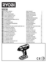
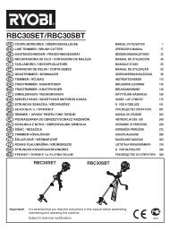
DESCRIPTION<br />
1. Upper blade guard<br />
2. Handle<br />
3. Lower blade guard<br />
4. Dust bag<br />
5. Mitre table<br />
6. Mitre scale<br />
7. Lower guard lock lever<br />
8. Switch trigger<br />
9. No hands zone<br />
10. Mitre fence<br />
11. Bevel scale<br />
12. Throat plate<br />
13. Wrench<br />
14. Saw blade<br />
15. Exhaust port<br />
16. Spindle lock button<br />
17. Dust port<br />
18. Outer blade washer<br />
19. Framing square<br />
20. Fence screw<br />
21. Screw for bevel scale standard<br />
22. Positive stop adjustment screw<br />
23. Lock nuts<br />
24. Depth stop adjustment screw<br />
25. Hex nut<br />
26. Bevel scale adjust knob<br />
27. Carrier handle<br />
28. Mitre lock<br />
29. Lock pin
<strong>EMS</strong>-<strong>1221</strong> manual 13/11/03 14:27 Page 12<br />
F GB D E<br />
DESCRIPTION<br />
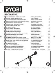
30. Blade bolt cover<br />
31. Blade bolt cover screw<br />
32. Notch<br />
33. Blade bolt<br />
34. Flat on spindle<br />
35. Inner blade washer<br />
ADJUSTMENTS<br />
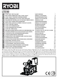
TO INSTALL BLADE (Fig. 4 - 6)<br />
DANGER<br />
A 210 mm blade is the maximum blade capacity<br />
of your saw. Never use a blade that is too thick to<br />
allow outer blade washer to engage with the flats<br />
on the spindle. Larger blades will come in<br />
contact with the blade guards, while thicker<br />
blades will prevent the blade screw from<br />
securing the blade on the spindle. Either of these<br />
situations will result in a serious accident and<br />
can cause serious personal injury.<br />
■ Unplug the mitre saw.<br />
WARNING<br />
Failure to unplug your saw could result in<br />
accidental starting causing possible serious<br />
personal injury.<br />
■ Push down the handle (2). Pull out the lock pin (29)<br />
let the cutting head raise to fully topest position.<br />
■ Gently raise the lower blade guard up until the blade<br />
bolt (33) expose. Loosen the blade bolt cover screw<br />
(31) move the blade cover upward to expose the<br />
blade bolt (33).<br />
■ Gently raise the lower blade guard (3) bracket,<br />
releasing lower blade guard from notch so that lower<br />
blade guard and blade bolt cover can be rotated up<br />
and back to expose the blade bolt.<br />
■ Depress the spindle lock button (16) and rotate the<br />
blade bolt until the spindle locks.<br />
Note: The blade bolt has left hand threads. Turn<br />
blade bolt clockwise to loosen.<br />
Remove outer blade washer (18). Do not remove inner<br />
blade washer (35).<br />
Wipe a drop of oil onto inner blade washer and outer<br />
blade washer where they contact the blade.<br />
I P NL S DK N FIN GR H CZ RUS RO PL<br />
English<br />
12<br />
WARNING<br />
If inner blade washer has been removed, replace<br />
it before placing blade on spindle. Failure to do<br />
so could cause an accident since blade will not<br />
tighten properly.<br />
■ Fit saw blade inside lower blade guard and onto<br />
spindle. The blade teeth point downward at the front<br />
of saw.<br />
CAUTION<br />
Always install the blade with the blade teeth<br />
and the arrow printed on the side of the blade<br />
pointing down at the front of the saw.<br />
The direction of blade rotation is also stamped<br />
with an arrow on the upper blade guard.<br />
■ Replace outer blade washer. The double "D" flats on<br />
the blade washers align with the flats on the spindle.<br />
■ Depress spindle lock button and replace blade bolt.<br />
Note: The blade bolt has left hand threads. Turn<br />
blade bolt counterclockwise to tighten.<br />
■ Using the blade wrench provided, tighten blade bolt<br />
securely.<br />
■ Remove the blade wrench and store it in a safe place<br />
for future use.<br />
■ Replace the lower blade guard and blade bolt cover.<br />
■ Retighten phillips screw securing blade bolt cover.<br />
Tighten screw securely.<br />
WARNING<br />
To prevent damage to the spindle lock, always<br />
allow motor to come to a complete stop before<br />
engaging spindle lock. Make sure the spindle<br />
lock button is not engaged before plugging the<br />
mitre saw.<br />
TO REMOVE BLADE (Fig. 4 - 6)<br />
■ Unplug the mitre saw.<br />
■ Gently raise the lower blade guard up until the blade<br />
bolt expose. Loosen the blade bolt cover screw move<br />
the blade cover upward to expose the blade bolt.<br />
■ Depress the spindle lock button and rotate the blade<br />
bolt until the spindle locks.<br />
■ Using the blade wrench provided, loosen and remove<br />
the blade bolt.<br />
Note: The blade bolt has left hand threads. Turn<br />
blade bolt clockwise to loosen.<br />
■ Remove outer blade washer. The blade can now be<br />
removed.
<strong>EMS</strong>-<strong>1221</strong> manual 13/11/03 14:27 Page 13<br />
F GB D E<br />
ADJUSTMENTS<br />
Your compound miter saw has been adjusted at the<br />
factory for making very accurate cuts. However, some of<br />
the components might have been bumped out of<br />
alignment during shipping. Also, over a period of time,<br />
readjustment will probably become necessary due to<br />
wear. After unpacking your saw, check the following<br />
adjustments before you begin using saw. Make any<br />
readjustments that are necessary and periodically check<br />
the parts alignment to make sure that your saw is cutting<br />
accurately.<br />
Note: Many of the illustrations in this manual show only<br />
portions of your compound miter saw. This is intentional<br />
so that we can clearly show points being made in the<br />
illustrations. Never operate your saw without all guards<br />
securely in place and in good operating condition.<br />
SQUARING THE MITER TABLE TO THE FENCE<br />
(Fig. 7 - 10)<br />
■ Unplug the mitre saw.<br />
■ Push down on the handle and pull out the lock pin to<br />
release the handle.<br />
■ Raise handle to its full raised position.<br />
■ Lift the mitre lock.<br />
■ Rotate the miter table (5) until the pointer is<br />
positioned at 0º.<br />
■ Push the mitre lock back down.<br />
■ Lay a framing square (19) flat on the miter table.<br />
Place one leg of the square against the fence. Place<br />
the other leg of the square beside the throat plate<br />
(12) in the miter table. The edge of the square and<br />
the throat plate in the miter table should be parallel.<br />
■ If the edge of the framing square and the throat plate<br />
in the miter table are not parallel, adjustments are<br />
needed.<br />
■ Using a 6 mm hex key, loosen the fence screws (20)<br />
securing the fence. Adjust the fence left or right until<br />
the framing square and throat plate are parallel.<br />
■ Retighten the screws securely and recheck the fenceto-table<br />
alignment.<br />
SQUARING THE SAW BLADE TO THE FENCE<br />
(Fig. 11 - 14)<br />
■ Pull the handle all the way down and engage the lock<br />
pin to hold the handle in transport position.<br />
■ Lift the mitre lock.<br />
■ Rotate the miter table until the pointer is positioned<br />
at 0º.<br />
I P NL S DK N FIN GR H CZ RUS RO PL<br />
English<br />
13<br />
■ Push the mitre lock (28) back down.<br />
■ Lay a framing square flat on the miter table. Place one<br />
leg of the square against the fence. Slide the other leg<br />
of the square against the flat part of saw blade.<br />
Note: Make sure that the square contacts the flat part<br />
of the saw blade, not the blade teeth.<br />
■ The edge of the square and the saw blade should be<br />
parallel.<br />
■ If the front or back edge of the saw blade angles<br />
away from the square, adjustments are needed.<br />
■ Using a 6 mm hex key, loosen the screws for bevel<br />
scale stand (21) that secure the mounting bracket to<br />
the mitre table.<br />
■ Rotate the mounting bracket left or right until the saw<br />
blade is parallel with the square.<br />
■ Retighten the screws securely and recheck the bladeto-fence<br />
alignment.<br />
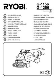
SQUARING THE BLADE TO THE MITER TABLE<br />
(Fig. 15)<br />
■ Pull the handle all the way down and engage the lock<br />
pin to hold the handle in transport position.<br />
■ Lift up the mitre lock.<br />
■ Rotate the miter table until the pointer is positioned<br />
at 0º.<br />
■ Push the mitre lock back down.<br />
■ Loosen bevel lock knob and set handle at 0 º bevel<br />
(blade set 90º to miter table). Tighten bevel lock knob.<br />
■ Place a combination square against the miter table<br />
and the flat part of saw blade.<br />
Note: Make sure that the square contacts the flat part<br />
of the saw blade, not the blade teeth.<br />
■ Rotate the blade by hand and check the blade-totable<br />
alignment at several points.<br />
■ The edge of the square and the saw blade should be<br />
parallel.<br />
■ Using a 10 mm wrench or adjustable wrench, loosen<br />
the lock nut (23) securing positive stop adjustment<br />
screw (22). Also loosen bevel lock knob (26).<br />
■ Adjust positive stop adjustment screw to bring saw<br />
blade into alignment with the square.<br />
■ If the top or bottom of the saw blade angles away<br />
from the square, adjustments are needed.<br />
■ Retighten bevel lock knob. Next, retighten lock nut<br />
securing the positive stop adjustment screw. Recheck<br />
blade-to-table alignment.<br />
Note: The above procedure can be used to check<br />
blade squareness of the saw blade to the miter table<br />
at both 0º and 45º angles.
<strong>EMS</strong>-<strong>1221</strong> manual 13/11/03 14:27 Page 14<br />
F GB D E<br />
ADJUSTMENTS<br />
PIVOT ADJUSTMENTS<br />
Note: These adjustments were made at the factory and<br />
normally do not require readjustment.<br />
TRAVEL PIVOT ADJUSTMENT<br />
■ The handle should rise completely to the up position<br />
by itself.<br />
■ If the handle does not raise by itself or if there is play<br />
in the pivot joints, have saw repaired by a qualified<br />
service technician at a <strong>Ryobi</strong> Store or Repair Center<br />
to avoid risk of personal injury.<br />
BEVEL PIVOT ADJUSTMENT<br />
■ Your compound miter saw should bevel easily by<br />
loosening bevel lock knob and tilting saw arm to<br />
the left.<br />
■ If movement is tight or if there is play in the pivot, have<br />
saw repaired by a qualified service technician at your<br />
nearest Repair Center to avoid risk of personal injury.<br />
DEPTH STOP<br />
The depth stop limits the blade's downward travel.<br />
It allows the blade to go below the miter table enough to<br />
maintain full cutting capacities. The depth stop positions<br />
the blade 6.4 mm from the miter table support.<br />
Note: The miter table support is located inside miter<br />
table.<br />
The depth stop is factory set to provide maximum cutting<br />
capacity for the 210 mm saw blade provided with your<br />
saw. Therefore, the saw blade provided should never<br />
need adjustments.<br />
However, when the diameter of the blade has been<br />
reduced due to sharpening, it may be necessary to adjust<br />
the depth stop to provide maximum cutting capacity.<br />
Also, when a new blade is installed, it is necessary to<br />
check the clearance of the blade to the miter table support<br />
before starting the saw. Make adjustments if needed.<br />
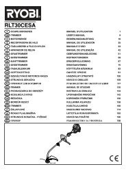
DEPTH STOP ADJUSTMENTS (Fig. 19)<br />
■ To adjust the depth stop use a 17 mm wrench or<br />
adjustable wrench and loosen the hex nut (25) at the<br />
rear of the miter handle.<br />
■ Use the 5 mm hex key provided to adjust the depth<br />
stop adjustment screw (24). The saw blade is lowered<br />
by turning the screw counterclockwise and raised by<br />
turning the screw clockwise.<br />
I P NL S DK N FIN GR H CZ RUS RO PL<br />
English<br />
14<br />
■ Lower the blade into the throat plate of the miter<br />
table. Check blade clearance and maximum cutting<br />
distance (distance from fence where blade enters)<br />
to front of miter table slot.<br />
■ Readjust if necessary.<br />
WARNING<br />
Do not start your compound miter saw without<br />
checking for interference between the blade and<br />
the miter table support. Damage could result to<br />
the blade if it strikes the miter table support<br />
during operation of the saw.<br />
■ Tighten the hex nut with a 17 mm wrench or<br />
adjustable wrench.<br />
■ To prevent the depth stop adjustment screw from<br />
turning while tightening the hex nut, carefully hold it<br />
with the hex key while tightening the hex nut.<br />
OPERATION<br />
WARNING<br />
Before starting any cutting operation, clamp or<br />
bolt your mitre saw to a workbench. Never<br />
operate your mitre saw on the floor or in a<br />
crouched position. Failure to heed this warning<br />
can result in serious personal injury.<br />
WARNING<br />
To avoid serious personal injury, keep your<br />
hands outside the no hands zone (9). Never<br />
perform any cutting operation freehand (without<br />
holding workpiece against the fence). The blade<br />
could grab the workpiece if it slips or twists.<br />
CUTTING A SLOT IN THE THROAT PLATE<br />
In order to use your compound mitre saw, you must cut a<br />
slot through the zero clearance throat plate to allow for<br />
blade clearance. To cut the slot, set your saw at 0° mitre,<br />
turn saw on and allow the blade to reach full speed,<br />
then carefully make a straight cut as far as it will go<br />
through the throat plate.<br />
Turn your saw off and allow the blade to come to a<br />
complete stop before raising the saw arm.<br />
Next, adjust the bevel angle to 45°, turn your saw on and<br />
allow the blade to reach full speed, then carefully make<br />
another cut through the zero clearance throat plate.<br />
The slot in the throat plate will then be wide enough to<br />
allow the blade to pass through it at any angle from<br />
0° to 45°.
<strong>EMS</strong>-<strong>1221</strong> manual 13/11/03 14:27 Page 15<br />
F GB D E<br />
OPERATION<br />
CUTTING WITH YOUR COMPOUND MITRE SAW<br />
WARNING<br />
When using a G-clamp to secure your<br />
workpiece, clamp workpiece on one side of the<br />
blade only. The workpiece must remain free on<br />
one side of the blade to prevent the blade from<br />
binding in workpiece. The workpiece binding the<br />
blade will cause motor stalling and kickback.<br />
This situation could cause an accident resulting<br />
in possible serious personal injury.<br />
CROSSCUTTING (Fig. 20)<br />
A crosscut is made by cutting across the grain of the<br />
workpiece. A straight crosscut is made with the mitre<br />
table set at the 0° position. Mitre crosscuts are made with<br />
the mitre table set at some angle other than zero.<br />
TO CROSSCUT WITH YOUR MITRE SAW<br />
■ Lift handle to its full height.<br />
■ Loosen the mitre lock knob. Rotate the mitre lock<br />
knob approximately one-half turn to the left to loosen.<br />
■ Press the mitre lock button down with your thumb<br />
and hold.<br />
■ Rotate the control arm until the pointer aligns with the<br />
desired angle on the mitre scale.<br />
■ Release the mitre lock button.<br />
Note: You can quickly locate 0°, 22-1/2° left or right,<br />
and 45° left or right by releasing the lock button as you<br />
rotate the table.<br />
■ Tighten the mitre lock knob securely.<br />
WARNING<br />
To avoid serious personal injury, always tighten<br />
the mitre lock knob securely before making a cut.<br />
Failure to do so could result in movement of the<br />
control arm or mitre table while making a cut.<br />
■ Place the workpiece flat on the mitre table with one<br />
edge securely against the fence. If the board is<br />
warped, place the convex side against the fence.<br />
If the concave edge of a board is placed against the<br />
fence, the board could collapse on the blade at the<br />
end of the cut, jamming the blade.<br />
■ When cutting long pieces of lumber or molding,<br />
support the opposite end of the stock with a roller<br />
stand or with a work surface level with the saw table.<br />
■ Align cutting line on the workpiece with the edge of<br />
saw blade.<br />
I P NL S DK N FIN GR H CZ RUS RO PL<br />
English<br />
15<br />
■ Grasp the stock firmly with one hand and secure it<br />
against the fence. Use the G-clamp to secure the<br />
workpiece when possible.<br />
■ Before turning on the saw, perform a dry run of the<br />
cutting operation just to make sure that no problems<br />
will occur when the cut is made.<br />
■ Grasp the saw handle firmly then squeeze the switch<br />
trigger. Allow several seconds for the blade to reach<br />
maximum speed.<br />
■ Press the lower guard unlock lever for saw head<br />
release.<br />
■ Slowly lower the blade into and through the<br />
workpiece.<br />
■ Release the switch trigger and allow the saw blade to<br />
stop rotating before raising the blade out of<br />
workpiece. Wait until the electric brake stops blade<br />
from turning before removing the workpiece from the<br />
mitre table.<br />
BEVEL CUT (Fig. 18-21 & 25-26)<br />
A bevel cut is made by cutting across the grain of the<br />
workpiece with the blade set at an angle. A straight bevel<br />
cut is made with the mitre table set at the zero degree<br />
position and the blade set at an angle between 0° and 45°.<br />
■ Pull out the lock pin and lift saw arm to its full height.<br />
■ Loosen the mitre lock knob. Rotate the mitre lock<br />
knob approximately one-half turn to the left to loosen.<br />
■ Press the mitre lock button down with your thumb<br />
and hold.<br />
■ Rotate the control arm until the pointer aligns with<br />
zero on the mitre scale.<br />
■ Release the mitre lock button.<br />
Note: You can quickly locate zero by releasing the<br />
lock button as you rotate the table.<br />
■ Tighten the mitre lock knob securely.<br />
WARNING<br />
To avoid serious personal injury, always tighten<br />
the mitre lock knob securely before making a cut.<br />
Failure to do so could result in movement of the<br />
control arm or mitre table while making a cut.<br />
■ The 45° triangle on the mitre fence provides for the<br />
maximum clearance required for adjusting the mitre<br />
saw's angle when making a bevel or compound cut.<br />
■ Loosen the bevel lock knob and move the saw arm to<br />
the left to the desired bevel angle.<br />
■ Bevel angles can be set from 0° to 45°.<br />
■ Once the saw arm has been set at the desired angle,<br />
securely tighten the bevel lock knob.
<strong>EMS</strong>-<strong>1221</strong> manual 13/11/03 14:27 Page 16<br />
F GB D E<br />
OPERATION<br />
■ Place the workpiece flat on the mitre table with one<br />
edge securely against the fence. If the board is<br />
warped, place the convex side against the fence.<br />
If the concave edge of a board is placed against the<br />
fence, the board could collapse on the blade at the<br />
end of the cut, jamming the blade.<br />
■ When cutting long pieces of lumber or molding,<br />
support the opposite end of the stock with a roller<br />
stand or with a work surface level with the saw table.<br />
■ Align the cutting line on the workpiece with the edge<br />
of saw blade.<br />
■ Grasp the stock firmly with one hand and secure it<br />
against the fence. Use the optional clamp to secure<br />
the workpiece when possible.<br />
WARNING<br />
To avoid serious personal injury, always keep<br />
your hands outside the no hands zone. Never<br />
perform any cutting operation freehand (without<br />
holding workpiece against the fence). The blade<br />
could grab the workpiece if it slips or twists.<br />
■ Before turning on the saw, perform a dry run of the<br />
cutting operation just to make sure that no problems<br />
will occur when the cut is made.<br />
■ Grasp the saw handle firmly then squeeze the switch<br />
trigger. Allow several seconds for the blade to reach<br />
maximum speed.<br />
■ Press the lower guard unlock lever for saw head<br />
release.<br />
■ Slowly lower the blade into and through the<br />
workpiece.<br />
■ Release the switch trigger and allow the saw blade to<br />
stop rotating before raising the blade out of<br />
workpiece. Wait until the electric brake stops blade<br />
from turning before removing the workpiece from the<br />
mitre table.<br />
COMPOUND MITRE CUT<br />
To make this type of cut the control arm on the mitre table<br />
must be rotated to the correct angle and the saw arm<br />
must be tilted to the correct bevel angle. Care should<br />
always be taken when making compound mitre setups<br />
due to the interaction of the two angle settings.<br />
Adjustments of mitre and bevel settings are<br />
interdependent with one another. Each time you adjust the<br />
mitre setting you change the effect of the bevel setting.<br />
Also, each time you adjust the bevel setting you change<br />
the effect of the mitre setting.<br />
I P NL S DK N FIN GR H CZ RUS RO PL<br />
English<br />
16<br />
It may take several settings to obtain the desired cut.<br />
The first angle setting should be checked after setting the<br />
second angle, since adjusting the second angle affects<br />
the first.<br />
Once the two correct settings for a particular cut have<br />
been obtained, always make a test cut in scrap material<br />
before making a finish cut in good material.<br />
TO MAKE A COMPOUND CUT WITH YOUR MITRE SAW<br />
■ Pull out the lock pin and lift handle to its full height.<br />
■ Loosen the mitre lock knob. Rotate the mitre table<br />
approximately one-half turn to the left to loosen.<br />
■ Press the mitre lock button down with your thumb<br />
and hold.<br />
■ Rotate the table until the pointer aligns with zero on<br />
the mitre scale.<br />
■ Release the mitre lock button.<br />
Note: You can quickly locate 0°, 15°, 22-1/2°, left or<br />
right, 30° and 45° left or right by releasing the mitre<br />
lock button as you rotate the control arm. The mitre<br />
lock button will seat itself in one of the positive stop<br />
notches, located in mitre table frame.<br />
■ Tighten the mitre lock knob securely.<br />
WARNING<br />
To avoid serious personal injury, always tighten<br />
the mitre lock handle securely before making a<br />
cut. Failure to do so could result in movement of<br />
the control arm or mitre table while making a cut.<br />
■ Loosen the bevel lock knob and move the handle to<br />
the left to the desired bevel angle.<br />
■ Bevel angles can be set from 0° to 45°.<br />
■ Once the handle has been set at the desired angle,<br />
securely tighten the bevel lock knob.<br />
■ Recheck mitre angle setting. Make a test cut in scrap<br />
material.<br />
■ Place the workpiece flat on the mitre table with one<br />
edge securely against the fence. If the board is<br />
warped, place the convex side against the fence.<br />
If the concave edge of a board could collapse on the<br />
blade at the end of the cut, jamming the blade.<br />
■ When cutting long pieces of lumber or molding, support<br />
the opposite end of the stock with a roller stand or with<br />
a work surface level with the saw table.<br />
■ Align the cutting line on the workpiece with the edge<br />
of saw blade.<br />
■ Grasp the stock firmly with one hand and secure it<br />
against the fence. Use the G-clamp to secure the<br />
workpiece when possible.
<strong>EMS</strong>-<strong>1221</strong> manual 13/11/03 14:27 Page 17<br />
F GB D E<br />
OPERATION<br />
WARNING<br />
To avoid serious personal injury, always keep<br />
your hands outside the no hands zone. Never<br />
perform any cutting operation freehand (without<br />
holding workpiece against the fence). The blade<br />
could grab the workpiece if it slips or twists.<br />
■ Before turning on the saw, perform a dry run of the<br />
cutting operation just to make sure that no problems<br />
will occur when the cut is made.<br />
■ Grasp the saw handle firmly then squeeze the switch<br />
trigger. Allow several seconds for the blade to reach<br />
maximum speed.<br />
■ Press the lower guard unlock lever for saw head<br />
release.<br />
■ Slowly lower the blade into and through the<br />
workpiece.<br />
■ Release the switch trigger and allow the saw blade to<br />
stop rotating before raising the blade out of<br />
workpiece. Wait until the electric brake stops blade<br />
from turning before removing the workpiece from the<br />
mitre table.<br />
SUPPORT LONG WORKPIECES (Fig. 24)<br />
Long workpieces need extra supports. Supports should<br />
be placed along the workpiece so it does not sag.<br />
The support should let the workpiece lay flat on the base<br />
of the saw and work table during the cutting operation.<br />
Use the optional clamp to secure the workpiece.<br />
WARNING<br />
To avoid serious personal injury, always keep<br />
your hands outside the no hands zone. Never<br />
perform any cutting operation freehand (without<br />
holding workpiece against the fence). The blade<br />
could grab the workpiece if it slips or twists.<br />
I P NL S DK N FIN GR H CZ RUS RO PL<br />
English<br />
17<br />
CUTTING WARPED MATERIAL (Fig. 25 & 26)<br />
When cutting warped material, always make sure it is<br />
positioned on the mitre table with the convex side against<br />
the fence.<br />
If the warped material is positioned the wrong way, it will<br />
pinch the blade near the completion of the cut.<br />
WARNING<br />
To avoid a binding condition and to avoid serious<br />
personal injury, never position the concave edge<br />
of bowed or warped material against the fence.
<strong>EMS</strong>-<strong>1221</strong> manual 13/11/03 14:27 Page 151<br />
F<br />
GARANTIE - CONDITIONS<br />
Ce produit <strong>Ryobi</strong> est garanti contre les vices de fabrication et les pièces<br />
défectueuses pour une durée de vingt-quatre (24) mois, à compter de la<br />
date faisant foi sur l'original de la facture établie par le revendeur à<br />
l'utilisateur final.<br />
Les détériorations provoquées par l'usure normale, par une utilisation<br />
ou un entretien anormal ou non autorisé, ou par une surcharge sont<br />
exclues de la présente garantie de même que les accessoires tels que<br />
batteries, ampoules, lames, embouts, sacs, etc.<br />
En cas de mauvais fonctionnement au cours de la période de garantie,<br />
veuillez envoyer le produit NON DÉMONTÉ avec la preuve d'achat à votre<br />
fournisseur ou au Centre Service Agréé <strong>Ryobi</strong> le plus proche de chez vous.<br />
Vos droits légaux se rapportant aux produits défectueux ne sont pas<br />
remis en cause par la présente garantie.<br />
GB<br />
WARRANTY - STATEMENT<br />
All <strong>Ryobi</strong> products are guaranteed against manufacturing defects and<br />
defective parts for a period of twenty four (24) months from the date stated<br />
on the original invoice drawn up by the retailer and given to the end user.<br />
Deterioration caused by normal wear and tear, unauthorised or improper<br />
use or maintenance, or overload are excluded from this guarantee as are<br />
accessories such as battery packs, light bulbs, blades, fittings, bags, etc.<br />
In the event of malfunction during the warranty period, please take the<br />
NON-DISMANTLED product, along with the proof of purchase, to your<br />
retailer or nearest Authorised <strong>Ryobi</strong> Service Centre.<br />
This warranty in no way affects your legal rights concerning defective<br />
products.<br />
D<br />
GARANTIE - BEDINGUNGEN<br />
Für alle <strong>Ryobi</strong>-Produkte gilt eine Garantie gegen Material- und<br />
Verarbeitungsfehler für einen Zeitraum von vierundzwanzig (24) Monaten<br />
ab dem Datum der vom Wiederverkäufer für den Endbenutzer<br />
ausgestellten Originalrechnung.<br />
Fehler, die auf Grund einer normalen Abnutzung, einer unberechtigten oder<br />
falschen Wartung oder Handhabung oder durch eine Überbelastung auftreten,<br />
sind von der Garantie ausgeschlossen. Dies gilt auch für Zubehörteile wie<br />
Batterien, Glühbirnen, Sägeblätter, Ansatzstücke, Beutel usw.<br />
Senden Sie das Produkt im Fall eines Defekts innerhalb des<br />
Garantiezeitraumes in NICHT ZERLEGTEM Zustand zusammen mit dem<br />
Kaufnachweis an Ihren Händler oder Ihr nächstes <strong>Ryobi</strong>-<br />
Kundendienstzentrum zurück.<br />
Diese Garantie hat keine Auswirkungen auf Ihre gesetzlichen Rechte in<br />
Bezug auf fehlerhafte Produkte.<br />
E<br />
GARANTÍA - CONDICIONES<br />
Este producto <strong>Ryobi</strong> está garantizado contra los defectos de fabricación<br />
y las piezas defectuosas por un período de veinticuatro (24) meses, a<br />
partir de la fecha que figura en el original de la factura establecida por<br />
el distribuidor al usuario final.<br />
Se excluyen de la presente garantía los deterioros provocados por un<br />
desgaste normal, una utilización o mantenimiento incorrecto o no<br />
autorizado, y una sobrecarga, así como los diversos accesorios: baterías,<br />
bombillas, hojas, puntas, bolsas, etc.<br />
En caso de funcionamiento incorrecto durante el período de la garantía,<br />
envíe el producto SIN DESMONTAR con la prueba de compra a su proveedor<br />
o al Centro de Servicio Acreditado <strong>Ryobi</strong> más cercano a su domicilio.<br />
Los derechos legales relacionados con los productos defectuosos no<br />
son cuestionados por la presente garantía.<br />
I<br />
GARANZIA - CONDIZIONI<br />
Questo prodotto <strong>Ryobi</strong> è garantito contro tutti i difetti di fabbricazione e<br />
pezzi difettosi per una durata di ventiquattro (24) mesi, a partire dalla<br />
data indicata sull’originale della fattura compilata dal rivenditore e<br />
consegnata all’utente finale.<br />
Il deterioramento provocato dall’usura normale, da un utilizzo o una<br />
manutenzione non conformi o non autorizzati, o da un sovraccarico,<br />
è escluso dalla presente garanzia. La garanzia è esclusa anche per gli<br />
accessori come batterie, lampadine, lame, punte, borse, ecc.<br />
In caso di malfunzionamento nel corso del periodo di garanzia, riportare<br />
il prodotto NON SMONTATO corredato della prova d’acquisto al fornitore<br />
o al più vicino Centro di Assistenza Autorizzato <strong>Ryobi</strong>.<br />
II diritti legali relativi ai prodotti difettosi non sono rimessi in causa dalla<br />
presente garanzia.<br />
P<br />
GARANTIA - CONDIÇÕES<br />
Este produto <strong>Ryobi</strong> está garantido contra os vícios de fabrico e as peças<br />
defeituosas por um prazo de vinte e quatro (24) meses, a contar da data<br />
que faz fé no original da factura emitida pelo vendedor ao utilizador final.<br />
As deteriorações provocadas pelo desgaste normal, por uma utilização<br />
ou uma manutenção anormal ou não autorizada, ou por uma sobrecarga<br />
ficam excluídas da presente garantia assim como os acessórios tais<br />
como baterias, lâmpadas, lâminas, ponteiras, sacos, etc.<br />
No caso de mau funcionamento durante o período de garantia, queira<br />
enviar o produto NÃO DESMONTADO com a prova de compra ao seu<br />
fornecedor ou ao Centro de Serviço Autorizado <strong>Ryobi</strong> mais próximo.<br />
Os seus direitos legais relativos aos produtos defeituosos não são<br />
prejudicados pela presente garantia.<br />
NL<br />
GARANTIEVOORWAARDEN<br />
Dit <strong>Ryobi</strong> product is gewaarborgd tegen fabricagefouten en defecte<br />
onderdelen gedurende een periode van vierentwintig (24) maanden, te<br />
rekenen vanaf de officiële datum op het origineel van de door de<br />
wederverkoper aan de eindgebruiker uitgeschreven rekening.<br />
Beschadigingen veroorzaakt door normale slijtage, door abnormaal of<br />
ongeoorloofd gebruik of onderhoud, of door overbelasting vallen niet<br />
onder deze garantie, evenmin als accu's, lampen, bits, snijbladen, zakken<br />
enz.<br />
In geval van slechte werking tijdens de garantieperiode, wordt u verzocht<br />
het NIET GEDEMONTEERDE product samen met de koopbon aan uw<br />
leverancier of aan het dichtstbijzijnde <strong>Ryobi</strong> servicecentrum te sturen.<br />
Deze garantie doet niet af aan uw wettelijke rechten met betrekking tot<br />
defecte producten.<br />
S<br />
GARANTI - VILLKOR<br />
<strong>Ryobi</strong> garanterar denna produkt mot fabrikationsfel och defekta delar<br />
under tjugofyra (24) månader, räknat från det datum som anges på<br />
originalfakturan fastställd av återförsäljaren och överlämnad till<br />
slutanvändaren.<br />
Denna garanti täcker inte skador som förorsakas av normalt slitage,<br />
av onormal eller otillåten användning eller skötsel, eller av överbelastning.<br />
Den täcker inte heller tillbehör som batterier, glödlampor, blad, ändstycken,<br />
påsar, osv.<br />
I händelse av felaktig funktion medan garantin är i kraft skall produkten<br />
sändas UTAN ATT DEMONTERAS tillsammans med inköpsbeviset till<br />
leverantören eller till närmaste servicecenter som auktoriserats av <strong>Ryobi</strong>.<br />
De rättigheter som lagen ger i förhållande till defekta produkter ifrågasätts<br />
inte av denna garanti.
<strong>EMS</strong>-<strong>1221</strong> manual 13/11/03 14:27 Page 153<br />
F<br />
GB<br />
D<br />
E<br />
I<br />
P<br />
HU<br />
CZ<br />
DÉCLARATION DE CONFORMITÉ<br />
Nous déclarons sous notre propre responsabilité que ce produit<br />
est en conformité avec les normes ou documents normalisés<br />
suivants:<br />
EN61029-1, EN55014, EN60555-3, 89/392/EWG, 93/68/EWG,<br />
73/23/EWG, 89/336/EEC<br />
DECLARATION OF CONFORMITY<br />
We declare under our sole responsibility that this product is<br />
in conformity with the following standards or standardized<br />
documents.<br />
EN61029-1, EN55014, EN60555-3, 89/392/EWG, 93/68/EWG,<br />
73/23/EWG, 89/336/EEC<br />
KONFORMITÄTSERKLÄRUNG<br />
Wir erklären in alleiniger Verantwortung, dass dieses Produkt mit<br />
den folgenden Normen oder normativen Dokumenten<br />
übereinstimmt:<br />
EN61029-1, EN55014, EN60555-3, 89/392/EWG, 93/68/EWG,<br />
73/23/EWG, 89/336/EEC<br />
DECLARACIÓN DE CONFORMIDAD<br />
Declaramos bajo nuestra exclusiva responsabilidad que este<br />
producto es conforme a las siguientes normas o documentos<br />
normalizados:<br />
EN61029-1, EN55014, EN60555-3, 89/392/EWG, 93/68/EWG,<br />
73/23/EWG, 89/336/EEC<br />
DICHIARAZIONE DI CONFORMITÀ<br />
Dichiariamo, assumendo la piena responsabilitá di tale<br />
dichiarazione, che il prodotto é conforme alla seguenti normative<br />
e ai relativi documenti.<br />
EN61029-1, EN55014, EN60555-3, 89/392/EWG, 93/68/EWG,<br />
73/23/EWG, 89/336/EEC<br />
DECLARAÇÃO DE CONFORMIDADE<br />
Declaramos, sob nossa exclusiva responsabilidade, que este<br />
produto cumpre as seguintes normas ou documentos normativos.<br />
EN61029-1, EN55014, EN60555-3, 89/392/EWG, 93/68/EWG,<br />
73/23/EWG, 89/336/EEC<br />
SZABVÁNY RENDELKEZÉSEK<br />
Felelősségünk teljes tudatában kijelentjük, hogy a jelen termék<br />
megfelel a következő szabványoknak és előírásoknak:<br />
EN61029-1, EN55014, EN60555-3, 89/392/EWG, 93/68/EWG,<br />
73/23/EWG, 89/336/EEC<br />
PROHLÁŠENÍ O SHODĚ<br />
Prohlašujeme na svou zodpovědnost, že tento výrobek splňuje<br />
požadavky níže uvedených norem a závazných předpisů:<br />
EN61029-1, EN55014, EN60555-3, 89/392/EWG, 93/68/EWG,<br />
73/23/EWG, 89/336/EEC<br />
Machine: 210 mm mitre saw Type: <strong>EMS</strong>-<strong>1221</strong><br />
Name of company: <strong>Ryobi</strong> Technologies FRANCE S.A.<br />
Address: Z.I. PARIS NORD II<br />
209, RUE DE LA BELLE ÉTOILE<br />
95700 ROISSY EN FRANCE<br />
FRANCE<br />
Tel: +33-1-49 90 14 14 Fax: +33-1-49 90 14 29<br />
Name of company: <strong>Ryobi</strong> Technologies (UK) Limited.<br />
Address: ANVIL HOUSE, TUNS LANE,<br />
HENLEY-ON-THAMES,<br />
OXFORDSHIRE, RG9 1SA<br />
UNITED KINGDOM<br />
Tel: +44-1491-848700 Fax: +44-1491-848701<br />
Name of company: <strong>Ryobi</strong> Technologies Gmbh<br />
Address: ITTERPARK 7<br />
D-40724 HILDEN<br />
GERMANY<br />
Tel: +49-2103-29580 Fax: +49-2103-295829<br />
NL<br />
S<br />
DK<br />
N<br />
FIN<br />
GR<br />
RU<br />
RO<br />
PL<br />
CONFORMITEITSVERKLARING<br />
Wij verklaren op onze eigen verantwoordelijkheid dat dit product<br />
voldoet aan de volgende normen of normatieve documenten.<br />
EN61029-1, EN55014, EN60555-3, 89/392/EWG, 93/68/EWG,<br />
73/23/EWG, 89/336/EEC<br />
FÖRSÄKRAN<br />
Vi intygar och ansvarar för, att denna produkt överensstämmer<br />
med följande normer och dokument.<br />
EN61029-1, EN55014, EN60555-3, 89/392/EWG, 93/68/EWG,<br />
73/23/EWG, 89/336/EEC<br />
KONFORMITETSERKLÆRING<br />
Vi erklærer på eget ansvar, at dette produkt er i overensstemmelse<br />
med følgende standarder eller standardiseringsdokumenter:<br />
EN61029-1, EN55014, EN60555-3, 89/392/EWG, 93/68/EWG,<br />
73/23/EWG, 89/336/EEC<br />
SAMSVARSERKLÆRING<br />
Vi erklærer på eget ansvar at dette produktet er i samsvar med<br />
følgende standarder og normative dokumenter:<br />
EN61029-1, EN55014, EN60555-3, 89/392/EWG, 93/68/EWG,<br />
73/23/EWG, 89/336/EEC<br />
TODISTUS STANDARDIN-MUKAISUUDESTA<br />
Todistamme täten ja vastaamme yksin siitä, että tämä tuote on alla<br />
lueteltujen standardien ja standardoimis-asiakirjojen vaatimusten<br />
mukainen.<br />
EN61029-1, EN55014, EN60555-3, 89/392/EWG, 93/68/EWG,<br />
73/23/EWG, 89/336/EEC<br />
∆HΛΩΣH ΣΥMMΡΦΩΣΗΣ<br />
∆ηλώνυµε υπευθύνως τι τ πρϊν αυτ συµµρύται<br />
πρς τα ακλυθα πρτυπα ή τυππιηµένα έγγραα:<br />
EN61029-1, EN55014, EN60555-3, 89/392/EWG, 93/68/EWG,<br />
73/23/EWG, 89/336/EEC<br />
áÄüÇãÖçàÖ é ëééíÇÖíëíÇàà ëíÄçÑÄêíÄå<br />
å˚ ÒÓ ‚ÒÂÈ ÓÚ‚ÂÚÒÚ‚ÂÌÌÓÒÚ¸˛ Á‡fl‚ÎflÂÏ, ˜ÚÓ Ì‡ÒÚÓfl˘‡fl ÔappleÓ‰Û͈Ëfl<br />
ÒÓÓÚ‚ÂÚÒÚ‚ÛÂÚ ÌËÊ ÒÎÂ‰Û˛˘ËÏ ÌÓappleÏ‡Ï Ë ‰ÓÍÛÏÂÌÚ‡Ï:<br />
EN61029-1, EN55014, EN60555-3, 89/392/EWG, 93/68/EWG,<br />
73/23/EWG, 89/336/EEC<br />
DECLARA‰IE DE CONFORMITATE<br />
Declarãm, cu toatã responsabilitatea cã acest produs este conform cu<br />
normele sau documentele urmãtoare:<br />
EN61029-1, EN55014, EN60555-3, 89/392/EWG, 93/68/EWG,<br />
73/23/EWG, 89/336/EEC<br />
DEKLARACJA ZGODNOŚCI<br />
Z całą odpowiedzialnością oświadczamy, że niniejszy produkt jest<br />
zgodny z normami czy też znormalizowanymi dokumentami<br />
wymienionymi poniżej:<br />
EN61029-1, EN55014, EN60555-3, 89/392/EWG, 93/68/EWG,<br />
73/23/EWG, 89/336/EEC<br />
Name/Title: Michel Violleau<br />
Président/Directeur Général<br />
Signature:<br />
Name/Title: Mark Pearson<br />
Managing Director<br />
Signature:<br />
Name/Title: Walter Martin Eichinger<br />
General Manager<br />
Signature: