TECHNICAL & SERVICE MANUAL DC INVERTER ... - Panasonic
TECHNICAL & SERVICE MANUAL DC INVERTER ... - Panasonic
TECHNICAL & SERVICE MANUAL DC INVERTER ... - Panasonic

You also want an ePaper? Increase the reach of your titles
YUMPU automatically turns print PDFs into web optimized ePapers that Google loves.
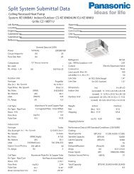
<strong>TECHNICAL</strong> & <strong>SERVICE</strong> <strong>MANUAL</strong><br />
CS-KS30NKU + CU-KS30NKUA<br />
CS-KS36NKU + CU-KS36NKUA<br />
<strong>DC</strong> <strong>INVERTER</strong> SPLIT SYSTEM AIR CONDITIONER<br />
Indoor Model No.<br />
CS-KS30NKU<br />
CS-KS36NKU<br />
IMPORTANT<br />
These air conditioners employ new<br />
refrigerant R410A.<br />
Pay special attention when<br />
servicing the unit.<br />
AIR CONDITIONER<br />
Outdoor Model No. Product Code No.<br />
CU-KS30NKUA 1 852 360 84<br />
CU-KS36NKUA 1 852 360 85<br />
Indoor Unit Outdoor Unit<br />
CS-KS30NKU<br />
CS-KS36NKU<br />
Product Code No.<br />
1 852 360 86<br />
1 852 360 87<br />
CU-KS30NKUA<br />
CU-KS36NKUA<br />
REFERENCE NO. SM700875
SAFETY PRECAUTIONS<br />
• Before doing repair work, please read the " SAFETY PRECAUTIONS" carefully and fully understand them.<br />
• The precautionary items here are divided into " Warning" and " Caution" items.<br />
Items in particular which may cause death or serious injury to the service personnel if the work is not performed correctly,<br />
are included in the " Warning" table.<br />
However, even precautionary items identified as " Caution" also have the potential for serious consequences<br />
if not performed correctly.<br />
Important safety precautions are described for all items in both categories. Be sure to carefully follow all of them.<br />
• Symbol Indication<br />
: This symbol indicates items to which we need to pay attention.<br />
In this triangle, a definite precautionary item is described.<br />
: This symbol indicates the item to be prohibited.<br />
In or close to this circle, a prohibited item is described.<br />
: This symbol indicates the items requiring special attention or instruction.<br />
In or close to this circle, a prohibited item is described.<br />
• After doing repair work, perform a test run to confirm that there are no abnormalities.<br />
At the same time, explain the precautions in use to the user.<br />
Warning<br />
Before performing an overhaul, disconnect the power plug or power cable from the unit.<br />
Performing the work with the power supplied to the unit, may cause an electric shock.<br />
When repair work or circuit inspection that requires power supply for the air conditioner, is to be performed,<br />
do not touch the charging section.<br />
Doing so may cause an electric shock.<br />
For the step-up capacitor attached to the electric section, perform the repair work after sufficiently discharging it.<br />
Insufficient capacitor discharge may cause an electric shock.<br />
Do not perform repair work on the electric sections with wet hands.<br />
Doing so may cause an electric shock.<br />
Do not start or stop the air conditioner by means of connecting or disconnecting the power plug.<br />
Doing so may cause an electric shock or fire.<br />
When conducting repair work only use components included in the parts list for the corresponding unit and perform<br />
the work with the appropriate tools.<br />
Incorrect or poor repair work may cause an electric shock or fire.<br />
Never modify the unit.<br />
Doing so may cause an electric shock or fire.<br />
Perform all electric work according to local applicable regulations related to electrical equipment or interior wiring<br />
regulation and make sure to use the exclusive circuit.<br />
Insufficient capacity to the electric circuit or defective arrangement results may cause an electric shock or fire.<br />
Make sure to replace any power cable or lead wire showing any signs of scratch or deterioration.<br />
Failure to do so may cause an electric shock, overheating or fire.<br />
Make sure that there is no dust on or slack in the power plug and insert fully into the socket.<br />
Dust or incomplete connections may cause an electric shock or fire.<br />
Do not damage or process the power cord, as it may cause an electric shock or fire.<br />
For the wiring between the indoor unit and outdoor unit, securely fix the specified cable onto the terminal plate.<br />
Poorly fixed wiring may cause a heat or fire.<br />
After connecting the wiring between the indoor unit and outdoor unit, attach the terminal cover securely.<br />
Incomplete attachment of the terminal cover may cause overheating or fire.<br />
2<br />
Prohibit<br />
Prohibit<br />
Prohibit<br />
Prohibit<br />
Prohibit
Warning<br />
If refrigerant gas blows off during the work, do not touch the refrigerant gas as it may cause frostbite.<br />
If refrigerant gas leaks during the work, ventilate the room.<br />
If refrigerant gas catches fire, harmful gas may be generated.<br />
Do not mix any gas other than the specified refrigerant gas in the refrigerating cycle.<br />
If air or other contaminants mix with the gas, pressure will become extremely high in the refrigerating cycle,<br />
which may cause a unit breakdown."<br />
When the welded section of the compressor intake or discharge pipe is to be disconnected, perform it in<br />
a well-ventilated place after sufficiently recovering the refrigerant gas.<br />
Any residue gas may jet out refrigerant or refrigerating machine oil, which may cause an injury.<br />
When the work is to be performed in a high place (About 2 meters or more), make sure to wear a safety helmet,<br />
gloves and safety belt. Insufficient safety gear may cause a serious injury in case of a fall.<br />
When the unit is to be relocated, confirm that the new installation location has sufficient strength for the weight of the unit.<br />
Insufficient strength of the installation location and incomplete installation work may cause an injury due to<br />
the unit falling.<br />
When the remote controller batteries are replaced, dispose of the old batteries out of the reach of children.<br />
If a child swallows a battery, make sure that the child gets immediate medical attention.<br />
Caution<br />
Do not wash the air conditioner with water, as this may cause an electric shock or fire.<br />
For the repair work in places with high humidity or moisture, make sure to ground the unit.<br />
Failure to do so may cause an electric shock.<br />
Confirm that the component attachment position, wiring condition, soldering condition and connector connection<br />
are normal.<br />
If not, it may cause overheating or fire.<br />
Confirm that the temperature around the compressor is not too high, and then perform the repair work.<br />
Failure to do so may cause a burn.<br />
Perform welding work in a place with good ventilation.<br />
If the work is performed in a poorly ventilated area, it might cause a lack of oxygen.<br />
If the installation plate or attachment frame has deteriorated due to corrosion, etc., replace it.<br />
Failure to do so may cause an injury due to the unit falling.<br />
When the cleaning is to be performed, make sure to turn off the power and pull out the plug.<br />
Touching the fan that is rotating at high speed may result in an injury.<br />
When the indoor unit is to be removed, do not place it on an incline.<br />
Doing so may cause wet furniture because water left inside may trickle down.<br />
Do not hold the sharp end of the unit or the aluminum fins, as it may cause an injury to your hand or finger.<br />
After repairs, make sure to measure the insulation resistance and confirm that the value is 1 Mohm or more.<br />
Any insulation error may cause an electric shock.<br />
After repairs, make sure to check the drainage of the indoor unit.<br />
Inappropriate drainage may cause wet furniture and floors due to water leakage.<br />
3<br />
Prohibit<br />
Prohibit<br />
Prohibit<br />
Prohibit<br />
Prohibit
SAFETY PRECAUTIONS<br />
TABLE OF CONTENTS<br />
1. OPERATING RANGE<br />
2. SPECIFICATIONS<br />
2-1. Unit Specifications<br />
2-2. Major Component Specifications<br />
2-3. Other Component Specifications<br />
Table of Contents<br />
3. DIMENSIONAL DATA .....................................................................................................................<br />
4. REFRIGERANT FLOW DIAGRAM<br />
4-1. Refrigerant Flow Diagram ...................................................................................................<br />
5. PERFORMANCE DATA<br />
5-1. Temperature Charts ............................................................................................................<br />
5-2. Cooling Capacity ................................................................................................................<br />
5-3. Cooling Capacity (Low Ambient) ........................................................................................<br />
5-4. Air Throw Distance Charts .................................................................................................<br />
6. ELECTRICAL DATA<br />
6-1. Electrical Characteristics<br />
6-2. Electric Wiring Diagrams<br />
7. FUNCTIONS<br />
7-1. Operation Functions<br />
7-2. Protective Functions<br />
..............................................................................................................<br />
.....................................................................................................................<br />
...................................................................................................................<br />
.............................................................................................................<br />
.......................................................................................<br />
.......................................................................................<br />
....................................................................................................<br />
....................................................................................................<br />
...........................................................................................................<br />
...........................................................................................................<br />
8. TROUBLESHOOTING (BEFORE CALLING FOR <strong>SERVICE</strong>)<br />
8-1. Precautions before Performing Inspection or Repair ...........................................................<br />
8-2. Method of Self-Diagnostics .................................................................................................<br />
8-3. Checking the Indoor and Outdoor Units ..............................................................................<br />
8-4. Trouble Diagnosis of Fan Motor ...........................................................................................<br />
8-5. Noise Malfunction and Electromagnetic Interference ..........................................................<br />
4<br />
Page<br />
2<br />
4<br />
6<br />
7<br />
11<br />
15<br />
16<br />
18<br />
19<br />
21<br />
23<br />
25<br />
27<br />
29<br />
31<br />
35<br />
36<br />
36<br />
39<br />
43<br />
45
9. CHECKING ELECTRICAL COMPONENTS<br />
9-1. Measurement of Insulation Resistance ...............................................................................<br />
9-2. Checking Continuity of Fuse on PCB Ass'y .........................................................................<br />
10. REFRIGERANT R410A:<br />
SPECIAL PRECAUTIONS WHEN SERVICING UNIT<br />
10-1. Characteristics of New Refrigerant R410A .........................................................................<br />
10-2. Checklist before Servicing ...................................................................................................<br />
10-3. Tools Specifically for R410A ................................................................................................<br />
10-4. Tubing Installation Procedures ............................................................................................<br />
10-5. In Case of Compressor Malfunction ....................................................................................<br />
10-6. In Case Refrigerant is Leaking ............................................................................................<br />
10-7. Charging Additional Refrigerant ..........................................................................................<br />
10-8. Retro-Fitting Existing Systems ............................................................................................<br />
APPENDIX A Operating Instructions<br />
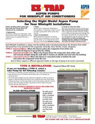
APPENDIX B INSTALLAION INSTRUCTIONS<br />
............................................................................................<br />
...............................................................................<br />
5<br />
Page<br />
46<br />
47<br />
48<br />
49<br />
50<br />
50<br />
51<br />
53<br />
54<br />
54<br />
A-1<br />
A-2
1. OPERATING RANGE<br />
Cooling<br />
Temperature Indoor Air Intake Temp. Outdoor Air Intake Temp.<br />
Maximum<br />
95 °F DB / 71 °F WB<br />
115 °F DB<br />
Minimum<br />
67 °F DB / 57 °F WB<br />
0 °F DB<br />
6
2. SPECIFICATIONS<br />
2-1. Unit Specifications<br />
Indoor Unit CS-KS30NKU<br />
Outdoor Unit CU-KS30NKUA<br />
Performance<br />
Electrical Rating<br />
Features<br />
Dimensions & Weight<br />
Voltage Rating<br />
Total Capacity<br />
BTU/h<br />
30,600 ( 10,900 to 30,600 )<br />
kW<br />
9.0 ( 3.2 to 9.0 )<br />
Sensible Capacity<br />
BTU/h<br />
18,600<br />
Latent Capacity<br />
BTU/h<br />
12,000<br />
Air Circulation (Hi/Me/Lo) ft 630 (1,070) / 530 (901) /412 (700)<br />
Available Voltage Range<br />
V<br />
187 to 253<br />
Running Amperes<br />
A<br />
16.5 ( 5.0 to 16.5 )<br />
Power Input<br />
W<br />
3,290 ( 1,000 to 3,290 )<br />
Power Factor %<br />
87<br />
SEER BTU/Wh 16.0<br />
Compressor Locked Rotor Amperes<br />
A 31.0<br />
Controls / Temperature Control<br />
Microprocessor / I.C. Thermister<br />
Control Unit<br />
Wireless Remote Control Unit<br />
Timer<br />
24-Hour ON or OFF Timer, 1-Hour OFF Timer<br />
Fan Speeds<br />
Indoor / Outdoor<br />
Auto and 3 steps / Auto (Hi, Me, Lo)<br />
Airflow Direction (Indoor) Horizontal<br />
Manual<br />
Vertical<br />
Auto<br />
Air Filter<br />
Washable, Anti-Mold<br />
Compressor<br />
<strong>DC</strong> Twin Rotary (Inverter)<br />
Refrigerant / Amount charged at shipment Ibs (g)<br />
R410A / 6.5 (2,950)<br />
Refrigerant Control<br />
Electric Expansion Valve<br />
Operation Sound Indoor : Hi/Me/Lo/Qt* dB-A<br />
49 / 44 / 39 / 32<br />
(*Qt = Quiet mode) Outdoor : Hi<br />
dB-A<br />
55<br />
Refrigerant Tubing Connections<br />
Flare Type<br />
Max. allowable tubing length at shipment<br />
ft (m)<br />
164 (50)<br />
Refrigerant Narrow tube inch (mm)<br />
3/8 (9.52)<br />
Tube Diameter Wide tube<br />
inch (mm)<br />
5/8 (15.88)<br />
Refrigerant Tube Kit<br />
Optional<br />
3 /min (m3 /h)<br />
Moisture Removal (High) Pints/h<br />
9.57<br />
EER BTU/h/W 9.30<br />
Fuse or Circuit Breaker Capacity A 35<br />
Unit Dimensions<br />
Height Width Depth<br />
Package Dimensions<br />
Height Width Depth<br />
Weight<br />
Net<br />
Shipping<br />
Shipping Volume<br />
Ibs (kg)<br />
Ibs (kg)<br />
cu.ft (m3 inch<br />
(mm)<br />
inch<br />
(mm)<br />
)<br />
Remarks: Rating conditions are:<br />
Cooling: Indoor air temperature 80 °F DB / 67 °F WB<br />
Outdoor air temperature 95 °F DB / 75 °F WB<br />
7<br />
Indoor Unit<br />
32.0<br />
39.7<br />
4.59<br />
230V Single-Phase 60Hz<br />
(14.5)<br />
(18.0)<br />
(0.13)<br />
Cooling<br />
Outdoor Unit<br />
183.0<br />
205.0<br />
15.88<br />
(83.0)<br />
(93.0)<br />
(0.45)<br />
< 230V ><br />
11-13/16 41-15/16 9-1/16 35-13/16 37-1/32 13-3/8<br />
(300 1,065 230) (910 940 340)<br />
12-7/32 44-7/8 14-31/32 42-3/8 40 16-3/8<br />
(310 1,140 380)<br />
(1,076 1,016 416)<br />
DATA SUBJECT TO CHANGE WITHOUT NOTICE.
Indoor Unit CS-KS30NKU<br />
Outdoor Unit CU-KS30NKUA<br />
Performance<br />
Electrical Rating<br />
Features<br />
Dimensions & Weight<br />
Voltage Rating<br />
Total Capacity<br />
BTU/h<br />
kW<br />
Sensible Capacity<br />
BTU/h<br />
Latent Capacity<br />
BTU/h<br />
Air Circulation (Hi/Me/Lo) ft<br />
Available Voltage Range<br />
V<br />
Running Amperes<br />
A<br />
Power Input<br />
W<br />
Power Factor<br />
%<br />
SEER BTU/Wh<br />
Compressor Locked Rotor Amperes<br />
A<br />
Controls / Temperature Control<br />
Control Unit<br />
Timer<br />
Fan Speeds<br />
Indoor / Outdoor<br />
Airflow Direction (Indoor)<br />
Air Filter<br />
Compressor<br />
Horizontal<br />
Vertical<br />
Refrigerant / Amount charged at shipment<br />
Refrigerant Control<br />
Ibs (g)<br />
Operation Sound Indoor : Hi/Me/Lo/Qt* dB-A<br />
(*Qt = Quiet mode) Outdoor : Hi<br />
dB-A<br />
Refrigerant Tubing Connections<br />
Max. allowable tubing length at shipment<br />
ft (m)<br />
Refrigerant Narrow tube inch (mm)<br />
Tube Diameter<br />
Refrigerant Tube Kit<br />
Wide tube<br />
inch (mm)<br />
3 /min (m3 /h)<br />
Moisture Removal (High) Pints/h<br />
EER BTU/h/W<br />
Fuse or Circuit Breaker Capacity A<br />
Unit Dimensions<br />
Height Width Depth<br />
Package Dimensions<br />
Height Width Depth<br />
Weight<br />
Net<br />
Shipping<br />
Shipping Volume<br />
Ibs (kg)<br />
Ibs (kg)<br />
cu.ft (m3 inch<br />
(mm)<br />
inch<br />
(mm)<br />
)<br />
Remarks: Rating conditions are:<br />
Cooling: Indoor air temperature 80 °F DB / 67 °F WB<br />
Outdoor air temperature 95 °F DB / 75 °F WB<br />
8<br />
32.0<br />
39.7<br />
4.59<br />
208V Single-Phase 60Hz<br />
30,600 ( 10,900 to 30,600 )<br />
9.0 ( 3.2 to 9.0 )<br />
18,600<br />
12,000<br />
630 (1,070) / 530 (901) /412 (700)<br />
18.0<br />
3,290<br />
Indoor Unit<br />
(14.5)<br />
(18.0)<br />
(0.13)<br />
Cooling<br />
9.57<br />
187 to 253<br />
( 5.0 to 18.0 )<br />
( 1,000 to 3,290 )<br />
88<br />
9.30<br />
16.0<br />
31.0<br />
35<br />
Microprocessor / I.C. Thermister<br />
Wireless Remote Control Unit<br />
24-Hour ON or OFF Timer, 1-Hour OFF Timer<br />
Auto and 3 steps / Auto (Hi, Me, Lo)<br />
Manual<br />
Auto<br />
Washable, Anti-Mold<br />
<strong>DC</strong> Twin Rotary (Inverter)<br />
R410A / 6.5 (2,950)<br />
Electric Expansion Valve<br />
49 / 44 / 39 / 32<br />
55<br />
Flare Type<br />
164 (50)<br />
3/8 (9.52)<br />
5/8 (15.88)<br />
Optional<br />
Outdoor Unit<br />
183.0<br />
205.0<br />
15.88<br />
(83.0)<br />
(93.0)<br />
(0.45)<br />
< 208V ><br />
11-13/16 41-15/16 9-1/16 35-13/16 37-1/32 13-3/8<br />
(300 1,065 230) (910 940 340)<br />
12-7/32 44-7/8 14-31/32 42-3/8 40 16-3/8<br />
(310 1,140 380)<br />
(1,076 1,016 416)<br />
DATA SUBJECT TO CHANGE WITHOUT NOTICE.
Indoor Unit CS-KS36NKU<br />
Outdoor Unit CU-KS36NKUA<br />
Performance<br />
Electrical Rating<br />
Features<br />
Dimensions & Weight<br />
Voltage Rating<br />
Total Capacity<br />
BTU/h<br />
kW<br />
Sensible Capacity<br />
BTU/h<br />
Latent Capacity<br />
BTU/h<br />
Air Circulation (Hi/Me/Lo) ft<br />
Available Voltage Range<br />
V<br />
Running Amperes<br />
A<br />
Power Input<br />
W<br />
Power Factor<br />
%<br />
SEER BTU/Wh<br />
Compressor Locked Rotor Amperes<br />
A<br />
Controls / Temperature Control<br />
Control Unit<br />
Timer<br />
Fan Speeds<br />
Indoor / Outdoor<br />
Airflow Direction (Indoor)<br />
Air Filter<br />
Compressor<br />
Horizontal<br />
Vertical<br />
Refrigerant / Amount charged at shipment<br />
Refrigerant Control<br />
Ibs (g)<br />
Operation Sound Indoor : Hi/Me/Lo/Qt* dB-A<br />
(*Qt = Quiet mode) Outdoor : Hi<br />
dB-A<br />
Refrigerant Tubing Connections<br />
Max. allowable tubing length at shipment<br />
ft (m)<br />
Refrigerant Narrow tube inch (mm)<br />
Tube Diameter<br />
Refrigerant Tube Kit<br />
Wide tube<br />
inch (mm)<br />
3 /min (m3 /h)<br />
Moisture Removal (High) Pints/h<br />
EER BTU/h/W<br />
Fuse or Circuit Breaker Capacity A<br />
Unit Dimensions<br />
Height Width Depth<br />
Package Dimensions<br />
Height Width Depth<br />
Weight<br />
Net<br />
Shipping<br />
Shipping Volume<br />
Ibs (kg)<br />
Ibs (kg)<br />
cu.ft (m3 inch<br />
(mm)<br />
inch<br />
(mm)<br />
)<br />
Remarks: Rating conditions are:<br />
Cooling: Indoor air temperature 80 °F DB / 67 °F WB<br />
Outdoor air temperature 95 °F DB / 75 °F WB<br />
9<br />
32.0<br />
39.7<br />
4.59<br />
230V Single-Phase 60Hz<br />
34,000 ( 10,900 to 34,000 )<br />
10.0 ( 3.2 to 10.0 )<br />
20,700<br />
13,300<br />
630 (1,070) / 530 (901) /412 (700)<br />
20.0<br />
4,000<br />
Indoor Unit<br />
(14.5)<br />
(18.0)<br />
(0.13)<br />
Cooling<br />
10.64<br />
187 to 253<br />
( 5.0 to 20.0 )<br />
( 1,000 to 4,000 )<br />
87<br />
8.50<br />
16.0<br />
31.0<br />
45<br />
Microprocessor / I.C. Thermister<br />
Wireless Remote Control Unit<br />
24-Hour ON or OFF Timer, 1-Hour OFF Timer<br />
Auto and 3 steps / Auto (Hi, Me, Lo)<br />
Manual<br />
Auto<br />
Washable, Anti-Mold<br />
<strong>DC</strong> Twin Rotary (Inverter)<br />
R410A / 6.5 (2,950)<br />
Electric Expansion Valve<br />
49 / 44 / 39 / 32<br />
55<br />
Flare Type<br />
164 (50)<br />
3/8 (9.52)<br />
5/8 (15.88)<br />
Optional<br />
Outdoor Unit<br />
183.0<br />
205.0<br />
15.88<br />
(83.0)<br />
(93.0)<br />
(0.45)<br />
< 230V ><br />
11-13/16 41-15/16 9-1/16 35-13/16 37-1/32 13-3/8<br />
(300 1,065 230) (910 940 340)<br />
12-7/32 44-7/8 14-31/32 42-3/8 40 16-3/8<br />
(310 1,140 380)<br />
(1,076 1,016 416)<br />
DATA SUBJECT TO CHANGE WITHOUT NOTICE.
Indoor Unit CS-KS36NKU<br />
Outdoor Unit CU-KS36NKUA<br />
Performance<br />
Electrical Rating<br />
Features<br />
Dimensions & Weight<br />
Voltage Rating<br />
Total Capacity<br />
BTU/h<br />
kW<br />
Sensible Capacity<br />
BTU/h<br />
Latent Capacity<br />
BTU/h<br />
Air Circulation (Hi/Me/Lo) ft<br />
Available Voltage Range<br />
V<br />
Running Amperes<br />
A<br />
Power Input<br />
W<br />
Power Factor<br />
%<br />
SEER BTU/Wh<br />
Compressor Locked Rotor Amperes<br />
A<br />
Controls / Temperature Control<br />
Control Unit<br />
Timer<br />
Fan Speeds<br />
Indoor / Outdoor<br />
Airflow Direction (Indoor)<br />
Air Filter<br />
Compressor<br />
Horizontal<br />
Vertical<br />
Refrigerant / Amount charged at shipment<br />
Refrigerant Control<br />
Ibs (g)<br />
Operation Sound Indoor : Hi/Me/Lo/Qt* dB-A<br />
(*Qt = Quiet mode) Outdoor : Hi<br />
dB-A<br />
Refrigerant Tubing Connections<br />
Max. allowable tubing length at shipment<br />
ft (m)<br />
Refrigerant Narrow tube inch (mm)<br />
Tube Diameter<br />
Refrigerant Tube Kit<br />
Wide tube<br />
inch (mm)<br />
3 /min (m3 /h)<br />
Moisture Removal (High) Pints/h<br />
EER BTU/h/W<br />
Fuse or Circuit Breaker Capacity A<br />
Unit Dimensions<br />
Height Width Depth<br />
Package Dimensions<br />
Height Width Depth<br />
Weight<br />
Net<br />
Shipping<br />
Shipping Volume<br />
Ibs (kg)<br />
Ibs (kg)<br />
cu.ft (m3 inch<br />
(mm)<br />
inch<br />
(mm)<br />
)<br />
Remarks: Rating conditions are:<br />
Cooling: Indoor air temperature 80 °F DB / 67 °F WB<br />
Outdoor air temperature 95 °F DB / 75 °F WB<br />
10<br />
32.0<br />
39.7<br />
4.59<br />
208V Single-Phase 60Hz<br />
34,000<br />
10.0<br />
21.9<br />
4,000<br />
Indoor Unit<br />
(14.5)<br />
(18.0)<br />
(0.13)<br />
Cooling<br />
( 10,900 to 34,000 )<br />
( 3.2 to 10.0 )<br />
20,700<br />
13,300<br />
630 (1,070) / 530 (901) /412 (700)<br />
10.64<br />
187 to 253<br />
( 5.0 to 21.9 )<br />
( 1,000 to 4,000 )<br />
88<br />
8.50<br />
16.0<br />
31.0<br />
45<br />
Microprocessor / I.C. Thermister<br />
Wireless Remote Control Unit<br />
24-Hour ON or OFF Timer, 1-Hour OFF Timer<br />
Auto and 3 steps / Auto (Hi, Me, Lo)<br />
Manual<br />
Auto<br />
Washable, Anti-Mold<br />
<strong>DC</strong> Twin Rotary (Inverter)<br />
R410A / 6.5 (2,950)<br />
Electric Expansion Valve<br />
49 / 44 / 39 / 32<br />
55<br />
Flare Type<br />
164 (50)<br />
3/8 (9.52)<br />
5/8 (15.88)<br />
Optional<br />
Outdoor Unit<br />
183.0<br />
205.0<br />
15.88<br />
(83.0)<br />
(93.0)<br />
(0.45)<br />
< 208V ><br />
11-13/16 41-15/16 9-1/16 35-13/16 37-1/32 13-3/8<br />
(300 1,065 230) (910 940 340)<br />
12-7/32 44-7/8 14-31/32 42-3/8 40 16-3/8<br />
(310 1,140 380)<br />
(1,076 1,016 416)<br />
DATA SUBJECT TO CHANGE WITHOUT NOTICE.
2-2. Major Component Specifications<br />
2-2-1. Indoor Unit<br />
Indoor Unit CS-KS30NKU<br />
Control PCB<br />
Fan<br />
Part No.<br />
Controls<br />
Control Circuit Fuse<br />
Type<br />
Q'ty ... Dia. and Length<br />
Fan Motor<br />
Type<br />
Model ... Q'ty<br />
No. of Poles<br />
Rough Measure RPM (Cool)<br />
Nominal Output<br />
Coil Resistance<br />
Flap Motor<br />
Type Stepping Motor<br />
Model<br />
24BYJ48-1256<br />
Rating<br />
<strong>DC</strong> 12V<br />
Coil Resistance<br />
(Ambient Temp. 77 °F (25 °C))<br />
Ohm<br />
Each Pair of Terminal : 200 +/- 7%<br />
Heat Exchanger Coil<br />
Coil<br />
Rows<br />
Fins Per inch<br />
Face Area<br />
inch (mm)<br />
W<br />
Ohm<br />
(Ambient Temp. 68 °F (20 °C))<br />
Safety Device<br />
Type<br />
Over-Current Protection<br />
Over-Heat Protection<br />
Run Capacitor Micro F<br />
VAC<br />
ft 2 (m 2 )<br />
11<br />
CB-CS-KS30NKU<br />
Microprocessor<br />
250V 3A<br />
Cross-Flow<br />
1 ... D3-15/16 / L32-1 (D100/L838)<br />
<strong>DC</strong> Motor<br />
SIC-41CVJ-D847-1 ... 1<br />
8<br />
1,370<br />
47<br />
-<br />
Internal Controller<br />
Yes<br />
Yes<br />
-<br />
-<br />
Aluminum Plate Fin / Copper Tube<br />
1 and 2<br />
19.5<br />
4.55 (0.423)<br />
DATA SUBJECT TO CHANGE WITHOUT NOTICE.
Indoor Unit CS-KS36NKU<br />
Control PCB<br />
Fan<br />
Part No.<br />
Controls<br />
Control Circuit Fuse<br />
Type<br />
Q'ty ... Dia. and Length<br />
Fan Motor<br />
Type<br />
Model ... Q'ty<br />
No. of Poles<br />
Rough Measure RPM (Cool)<br />
Nominal Output<br />
Coil Resistance<br />
Flap Motor<br />
Type<br />
Model<br />
Rating<br />
Coil Resistance Ohm<br />
(Ambient Temp. 77 °F (25 °C))<br />
Heat Exchanger Coil<br />
Coil<br />
Rows<br />
Fins Per inch<br />
Face Area<br />
inch (mm)<br />
W<br />
Ohm<br />
(Ambient Temp. 68 °F (20 °C))<br />
Safety Device<br />
Type<br />
Over-Current Protection<br />
Over-Heat Protection<br />
Run Capacitor Micro F<br />
VAC<br />
ft 2 (m 2 )<br />
12<br />
CB-CS-KS36NKU<br />
Microprocessor<br />
250V 3A<br />
Cross-Flow<br />
1 ... D3-15/16 / L32-1 (D100/L838)<br />
<strong>DC</strong> Motor<br />
SIC-41CVJ-D847-1 ... 1<br />
8<br />
1,370<br />
47<br />
-<br />
Internal Controller<br />
Yes<br />
Yes<br />
-<br />
-<br />
Stepping Motor<br />
24BYJ48-1256<br />
<strong>DC</strong> 12V<br />
Each Pair of Terminal : 200 +/- 7%<br />
Aluminum Plate Fin / Copper Tube<br />
1 and 2<br />
19.5<br />
4.55 (0.423)<br />
DATA SUBJECT TO CHANGE WITHOUT NOTICE.
2-2-2. Outdoor Unit<br />
Outdoor Unit CU-KS30NKUA<br />
P.C.Board<br />
Part No.<br />
Controls<br />
Circuit Fuse<br />
Compressor<br />
Fan<br />
Type<br />
Compressor Model / Nominal Output<br />
Compressor Oil ... Amount<br />
Pints (cc)<br />
Coil Resistance (Ambient Temp. 77 °F (25 °C)) Ohm<br />
Safety Device<br />
CT (Peak current cut-off control)<br />
Compressor Discharge Temp. Control<br />
Operation cut-off control in abnormal ambient Temp.<br />
Model<br />
Heat Exchanger Coil<br />
Coil<br />
Rows<br />
Fins per inch<br />
W<br />
Ohm<br />
Micro F<br />
VAC<br />
Control P.C.B<br />
CR-C3082-F<br />
Microprocessor<br />
400V 3.15A<br />
Noise Filer P.C.B<br />
POW-CH3082-B2<br />
-<br />
250V 25A<br />
<strong>DC</strong> Twin Rotary (Hermetic)<br />
C-9RVN273H0H / 2,250W<br />
FV68S ... 2.98 (1,400)<br />
T - R : 0.169<br />
T - S : 0.169<br />
R - S : 0.169<br />
<strong>DC</strong> Motor<br />
SIC-71FW-D8120-4A ... 1<br />
External Finish Acrylic baked-on enamel finish<br />
8<br />
750<br />
142<br />
-<br />
Internal Controller<br />
Yes<br />
Yes<br />
-<br />
-<br />
Aluminum Plate Fin / Copper Tube<br />
2<br />
21.2<br />
Face Area ft 2 (m 2 ) 8.05 (0.748)<br />
Yes<br />
Yes<br />
Yes<br />
H.I.C.Board<br />
HIC-CH3072R-C1<br />
-<br />
-<br />
Overload Relay CS-7L110<br />
Operation Temp. Open : 230 °F (110 °C), Close : 203 °F (95 °C)<br />
Run Capacitor<br />
Micro F<br />
-<br />
VAC<br />
-<br />
Crankcase Heater<br />
230V 30W<br />
Type<br />
Q'ty ... Dia. inch (mm)<br />
Fan Motor<br />
Type<br />
Model ... Q'ty<br />
No. of Poles<br />
Rough Measure RPM (Cool)<br />
Nominal Output<br />
Coil Resistance<br />
(Ambient Temp. 68 °F (20 °C))<br />
Safety Device<br />
Type<br />
Over- Current Protection<br />
Over- Heat Protection<br />
Run Capacitor<br />
13<br />
Propeller<br />
1 ... D19-9/32 (D490)<br />
DATA SUBJECT TO CHANGE WITHOUT NOTICE.
Outdoor Unit CU-KS36NKUA<br />
P.C.Board<br />
Part No.<br />
Controls<br />
Circuit Fuse<br />
Compressor<br />
Fan<br />
Type<br />
Compressor Model / Nominal Output<br />
Compressor Oil ... Amount<br />
Pints (cc)<br />
Coil Resistance (Ambient Temp. 77 °F (25 °C)) Ohm<br />
Safety Device<br />
CT (Peak current cut-off control)<br />
Compressor Discharge Temp. Control<br />
Operation cut-off control in abnormal ambient Temp.<br />
Model<br />
Heat Exchanger Coil<br />
Coil<br />
Rows<br />
Fins per inch<br />
W<br />
Ohm<br />
Micro F<br />
VAC<br />
Control P.C.B<br />
CR-C3682-F<br />
Microprocessor<br />
400V 3.15A<br />
Noise Filer P.C.B<br />
POW-CH3082-B2<br />
-<br />
250V 25A<br />
<strong>DC</strong> Twin Rotary (Hermetic)<br />
C-9RVN273H0H / 2,500W<br />
FV68S ... 2.98 (1,400)<br />
T - R : 0.169<br />
T - S : 0.169<br />
R - S : 0.169<br />
<strong>DC</strong> Motor<br />
SIC-71FW-D8120-4A ... 1<br />
External Finish Acrylic baked-on enamel finish<br />
8<br />
750<br />
142<br />
-<br />
Internal Controller<br />
Yes<br />
Yes<br />
-<br />
-<br />
Aluminum Plate Fin / Copper Tube<br />
2<br />
21.2<br />
Face Area ft 2 (m 2 ) 8.05 (0.748)<br />
Yes<br />
Yes<br />
Yes<br />
H.I.C.Board<br />
HIC-CH3072R-C1<br />
-<br />
-<br />
Overload Relay CS-7L110<br />
Operation Temp. Open : 230 °F (110 °C), Close : 203 °F (95°C)<br />
Run Capacitor<br />
Micro F<br />
-<br />
VAC<br />
-<br />
Crankcase Heater<br />
230V 30W<br />
Type<br />
Q'ty ... Dia. inch (mm)<br />
Fan Motor<br />
Type<br />
Model ... Q'ty<br />
No. of Poles<br />
Rough Measure RPM (Cool)<br />
Nominal Output<br />
Coil Resistance<br />
(Ambient Temp. 68 °F (20 °C))<br />
Safety Device<br />
Type<br />
Over- Current Protection<br />
Over- Heat Protection<br />
Run Capacitor<br />
14<br />
Propeller<br />
1 ... D19-9/32 (D490)<br />
DATA SUBJECT TO CHANGE WITHOUT NOTICE.
2-3. Other Component Specifications<br />
Indoor Unit CS-KS30NKU<br />
CS-KS36NKU<br />
Outdoor Unit CU-KS30NKUA<br />
CU-KS36NKUA<br />
Resistance (k ohm)<br />
10<br />
9<br />
8<br />
7<br />
6<br />
5<br />
4<br />
3<br />
2<br />
1<br />
0<br />
• Indoor air temp sensor<br />
(Model:KTEC-35-135-1)<br />
50 59 68 77 86 95 104<br />
(10) (15) (20) (25) (30) (35) (40)<br />
Temperature °F (°C)<br />
Resistance (k ohm)<br />
Resistance (k ohm)<br />
15<br />
200<br />
180<br />
160<br />
140<br />
120<br />
100<br />
80<br />
60<br />
40<br />
20<br />
0<br />
• Indoor heat exchanger sensor<br />
(Model:PTM-D51H-S6-1)<br />
• Compressor temp sensor<br />
(Model:TKS335B)<br />
32 50 68 86 104 122 140 158 176 194<br />
(0) (10) (20) (30) (40) (50) (60) (70) (80) (90)<br />
Temperature °F (°C)<br />
• Outdoor air temp sensor<br />
(Model:TKS295B)<br />
• Outdoor heat exchanger sensor<br />
(Model:TKS334B)<br />
• Heat sink temp sensor (HIC Board)<br />
(Model:TKS316B)<br />
40<br />
35<br />
30<br />
25<br />
20<br />
15<br />
10<br />
5<br />
0<br />
-4 5 14 23 32 41 50 59 68<br />
(-20)(-15)(-10) (-5) (0) (5) (10) (15) (20)<br />
Temperature °F (°C)
3. DIMENSIONAL DATA<br />
Indoor Unit CS-KS30NKU<br />
CS-KS36NKU<br />
2-3/32 25/32<br />
41-15/16 (1065)<br />
1-9/32<br />
5-9/16<br />
2-3/4<br />
7-23/32<br />
1-27/32 1-3/32<br />
4-9/16<br />
4-9/16<br />
11-13/16 (300)<br />
5-27/32<br />
Wide tube dia. 5/8" (15.88)<br />
Narrow tube dia. 3/8" (9.52)<br />
7-25/32<br />
2-3/8<br />
9-1/16 (230) (3/32)<br />
5/16 2-3/4<br />
16<br />
15-1/8 17-23/32<br />
9-3/32<br />
3-3/4 3-3/4 7-7/8<br />
2-11/16<br />
5-1/2<br />
1-15/32<br />
23/32<br />
2-3/8<br />
1-7/8<br />
11-13/16<br />
3-3/8<br />
7/16<br />
2-5/8<br />
2-5/8<br />
dia. 3-5/32<br />
5-3/16<br />
6-7/32<br />
1-7/8<br />
16-11/32<br />
17-21/32<br />
22-3/8<br />
16-11/32<br />
17-5/16<br />
dia. 3-5/32<br />
19-9/16<br />
Unit: inch(mm)<br />
(852-0-0010-196-00-0)
Outdoor Unit CU-KS30NKUA<br />
CU-KS36NKUA<br />
2-ID:1-1/4 holes (holes for drain)<br />
Of the 4-ID:1-1/4 holes, use 1 of 2 holes<br />
specified for drain use to install the port.<br />
Use rubber plugs to seal the remaining 3 holes.<br />
6-11/6 25-31/32 4-11/32<br />
2-15/16 2-15/16 2-3/8<br />
1/2<br />
8-5/8<br />
4-1/8<br />
13/32<br />
1-1/32<br />
16-5/32<br />
14-31/32<br />
13-3/8 (340)<br />
11-13/32<br />
1/2<br />
37-1/32 (940)<br />
Refrigerant tubing joint (Liquid tube)<br />
Flare connection dia.3/8" (9.52)<br />
17<br />
Refrigerant tubing joint (Gas tube)<br />
Flare connection dia.5/8" (15.88)<br />
35-13/16 (910)<br />
21/32<br />
31/32<br />
4-3/4<br />
6-23/32 19/32<br />
1-3/16<br />
1-27/32<br />
1-3/16<br />
1-27/32<br />
3/4<br />
14-11/32<br />
13-9/32<br />
1-15/16<br />
2-25/32<br />
4-11/32<br />
4-11/32<br />
2-25/32<br />
23/32<br />
1-3/16<br />
2-3/8<br />
1-15/16<br />
2-3/8<br />
7/16<br />
3/4<br />
2-5/32<br />
2-5/32<br />
Wiring outlet<br />
(knock-out holes dia.1-3/8, 1-3/32, 7/8, 1/2)<br />
3-3/8<br />
2-17/32<br />
2-17/32<br />
Wiring outlet<br />
(knock-out holes<br />
dia.1-3/8, 1-3/32, 7/8, 1/2)<br />
Unit: inch(mm)<br />
(852-0-0010-194-00-1)
4. REFRIGERANT FLOW DIAGRAM<br />
4-1. Refrigerant Flow Diagram<br />
Indoor Unit CS-KS30NKU<br />
CS-KS36NKU<br />
Indoor unit Outdoor unit<br />
Heat exchanger<br />
Wide tube<br />
O.D<br />
5/8"<br />
(15.88 mm)<br />
Narrow tube<br />
O.D.<br />
3/8"<br />
(9.52 mm)<br />
Outdoor Unit CU-KS30NKUA<br />
CU-KS36NKUA<br />
Wide tube<br />
service<br />
valve<br />
Narrow<br />
tube<br />
service<br />
valve<br />
Muffler<br />
Strainer<br />
18<br />
Sub<br />
Accumulator<br />
Main<br />
Accumulator<br />
Electric<br />
expansion<br />
valve<br />
M<br />
High pressure<br />
switch<br />
H.P.<br />
Compressor<br />
Heat exchanger<br />
Cooling cycle
5. PERFORMANCE DATA<br />
5-1. Temperature Charts<br />
Indoor Unit CS-KS30NKU<br />
Outdoor Unit CU-KS30NKUA<br />
Cooling Characteristics (RH : 46%, Indoor fan speed : High fan) (60Hz, 230V)<br />
(1) Low pressure performance chart<br />
Indoor discharge air temperature °F(°C) Low pressure at wide tube service valve<br />
Operating current (A)<br />
psig(MPaG)<br />
174<br />
(1.2)<br />
159<br />
(1.1)<br />
145<br />
(1.0)<br />
131<br />
(0.9)<br />
117<br />
(0.8)<br />
104<br />
(0.7)<br />
(2) Operating current performance chart<br />
(3) Indoor discharge air performance chart<br />
NOTE<br />
-4<br />
(-20)<br />
28<br />
26<br />
24<br />
22<br />
20<br />
18<br />
16<br />
14<br />
12<br />
10<br />
64.4 (18)<br />
60.8 (16)<br />
57.2 (14)<br />
53.6 (12)<br />
50.0 (10)<br />
46.4 (8)<br />
42.8 (6)<br />
-4<br />
(-20)<br />
-4<br />
(-20)<br />
5<br />
(-15)<br />
5<br />
(-15)<br />
5<br />
(-15)<br />
14<br />
(-10)<br />
14<br />
(-10)<br />
14<br />
(-10)<br />
23<br />
(-5)<br />
23<br />
(-5)<br />
23<br />
(-5)<br />
32<br />
(0)<br />
32<br />
(0)<br />
32<br />
(0)<br />
41<br />
(5)<br />
• Check each performance value in test-run mode. Electrical performance values represent a combined indoor/outdoor value.<br />
50<br />
(10)<br />
59<br />
(15)<br />
Outdoor inlet air DB temp. °F(°C)<br />
41<br />
(5)<br />
50<br />
(10)<br />
59<br />
(15)<br />
Outdoor inlet air DB temp. °F(°C)<br />
41<br />
(5)<br />
50<br />
(10)<br />
59<br />
(15)<br />
Outdoor inlet air DB temp. °F(°C)<br />
19<br />
68<br />
(20)<br />
68<br />
(20)<br />
68<br />
(20)<br />
Lo fan<br />
Indoor Indoor Air Air Temp.86°F Temp.86°F (30°C) (30°C)<br />
80°F 80°F (27°C) (27°C)<br />
Lo fan<br />
Lo fan<br />
75°F 75°F (24°C) (24°C)<br />
77<br />
(25)<br />
77<br />
(25)<br />
77<br />
(25)<br />
86<br />
(30)<br />
Indoor Indoor Air Temp.86°F Temp.86°F (30°C) (30°C)<br />
80°F 80°F (27°C) (27°C)<br />
75°F 75°F (24°C) (24°C)<br />
Indoor Indoor Air Air Temp.86°F Temp.86°F (30°C) (30°C)<br />
80°F (27°C)<br />
80°F (27°C)<br />
75°F (24°C)<br />
75°F (24°C)<br />
86<br />
(30)<br />
86<br />
(30)<br />
Hi Fan<br />
Hi Fan<br />
Hi Fan<br />
95<br />
(35)<br />
95<br />
(35)<br />
95<br />
(35)<br />
104<br />
(40)<br />
104<br />
(40)<br />
104<br />
(40)
Indoor Unit CS-KS36NKU<br />
Outdoor Unit CU-KS36NKUA<br />
Cooling Characteristics (RH : 46%, Indoor fan speed : High fan) (60Hz, 230V)<br />
(1) Low pressure performance chart<br />
Indoor discharge air temperature °F(°C) Low pressure at wide tube service valve<br />
Operating current (A)<br />
psig(MPaG)<br />
174<br />
(1.2)<br />
159<br />
(1.1)<br />
145<br />
(1.0)<br />
131<br />
(0.9)<br />
117<br />
(0.8)<br />
104<br />
(0.7)<br />
(2) Operating current performance chart<br />
(3) Indoor discharge air performance chart<br />
NOTE<br />
-4<br />
(-20)<br />
28<br />
26<br />
24<br />
22<br />
20<br />
18<br />
16<br />
14<br />
12<br />
10<br />
64.4 (18)<br />
60.8 (16)<br />
57.2 (14)<br />
53.6 (12)<br />
50.0 (10)<br />
46.4 (8)<br />
42.8 (6)<br />
-4<br />
(-20)<br />
-4<br />
(-20)<br />
5<br />
(-15)<br />
5<br />
(-15)<br />
5<br />
(-15)<br />
14<br />
(-10)<br />
14<br />
(-10)<br />
14<br />
(-10)<br />
23<br />
(-5)<br />
23<br />
(-5)<br />
23<br />
(-5)<br />
32<br />
(0)<br />
32<br />
(0)<br />
32<br />
(0)<br />
41<br />
(5)<br />
• Check each performance value in test-run mode. Electrical performance values represent a combined indoor/outdoor value.<br />
50<br />
(10)<br />
59<br />
(15)<br />
Outdoor inlet air DB temp. °F(°C)<br />
41<br />
(5)<br />
50<br />
(10)<br />
59<br />
(15)<br />
Outdoor inlet air DB temp. °F(°C)<br />
41<br />
(5)<br />
50<br />
(10)<br />
59<br />
(15)<br />
Outdoor inlet air DB temp. °F(°C)<br />
20<br />
68<br />
(20)<br />
68<br />
(20)<br />
68<br />
(20)<br />
Lo fan<br />
Indoor Indoor Air Air Temp.86°F Temp.86°F (30°C) (30°C)<br />
Lo fan<br />
Lo fan<br />
77<br />
(25)<br />
77<br />
(25)<br />
77<br />
(25)<br />
80°F (27°C)<br />
80°F (27°C)<br />
75°F 75°F (24°C) (24°C)<br />
80°F 80°F (27°C) (27°C)<br />
Indoor Indoor Air Air Temp.86°F Temp.86°F (30°C) (30°C)<br />
75°F 75°F (24°C) (24°C)<br />
Indoor Indoor Air Air Temp.86°F Temp.86°F (30°C) (30°C)<br />
80°F 80°F (27°C) (27°C)<br />
75°F 75°F (24°C) (24°C)<br />
86<br />
(30)<br />
86<br />
(30)<br />
86<br />
(30)<br />
Hi Fan<br />
Hi Fan<br />
Hi Fan<br />
95<br />
(35)<br />
95<br />
(35)<br />
95<br />
(35)<br />
104<br />
(40)<br />
104<br />
(40)<br />
104<br />
(40)
5-2. Cooling Capacity<br />
Indoor Unit : CS-KS30NKU<br />
Outdoor Unit : CU-KS30NKUA<br />
Power Supply : 230V Single Phase 60Hz<br />
< Cooling Capacity ><br />
RATING CAPACITY: 30,600 BTU/h AIR FLOW RATE: 630 CFM<br />
INDOOR OUTDOOR<br />
ENT. TEMP.<br />
NOTE<br />
o F ( o C) AMBIENT TEMP. o F ( o C)<br />
WB DB 65 75 85 95 105 115<br />
(18.3) (23.9) (29.4) (35.0) (40.6) (46.1)<br />
TC 26,540 27,120 27,710 27,910 24,890 17,310<br />
CI 2.07 2.43 2.79 3.01 3.04 2.40<br />
72 (22.2) SHC 19,190 19,430 19,800 19,920 18,330 14,660<br />
59 76 (24.4) SHC 21,510 21,880 22,120 22,250 20,660 16,990<br />
(15.0) 80 (26.7) SHC 23,960 24,330 24,570 24,690 23,100 17,310<br />
84 (28.9) SHC 26,280 26,650 26,890 27,020 24,890 17,310<br />
88 (31.1) SHC 26,540 27,120 27,710 27,910 24,890 17,310<br />
TC 31,580 30,910 30,160 29,630 25,270 17,560<br />
CI 2.12 2.48 2.85 3.07 3.04 2.40<br />
72 (22.2) SHC 18,330 17,970 17,600 17,360 15,150 11,730<br />
63 76 (24.4) SHC 20,660 20,290 19,920 19,680 17,480 14,050<br />
(17.2) 80 (26.7) SHC 23,100 22,740 22,370 22,120 20,050 16,500<br />
84 (28.9) SHC 25,430 25,060 24,690 24,450 22,370 17,560<br />
88 (31.1) SHC 27,750 27,510 27,020 26,770 24,690 17,560<br />
TC 32,420 31,780 31,050 # 30,600 25,550 17,760<br />
CI 2.17 2.55 2.93 3.14 3.04 2.40<br />
72 (22.2) SHC 15,150 14,790 14,420 14,300 12,100 8,920<br />
67 76 (24.4) SHC 17,480 17,110 16,870 16,620 14,420 11,240<br />
(19.4) 80 (26.7) SHC 19,920 19,560 19,310 19,070 16,870 13,690<br />
84 (28.9) SHC 22,250 22,000 21,640 21,390 19,190 16,010<br />
88 (31.1) SHC 24,570 24,330 23,960 23,710 21,510 17,760<br />
TC 33,130 32,540 31,840 31,490 25,710 17,880<br />
CI 2.24 2.63 3.02 3.22 3.04 2.40<br />
72 (22.2) SHC 11,730 11,480 11,120 11,000 8,670 5,860<br />
71 76 (24.4) SHC 14,050 13,810 13,440 13,320 11,120 8,310<br />
(21.7) 80 (26.7) SHC 16,500 16,250 15,890 15,770 13,560 10,750<br />
84 (28.9) SHC 18,820 18,580 18,330 18,210 15,890 13,070<br />
88 (31.1) SHC 21,150 20,900 20,660 20,530 18,210 15,400<br />
TC 33,630 33,090 32,430 32,190 25,730 17,900<br />
CI 2.31 2.71 3.11 3.30 3.04 2.40<br />
75 76 (24.4) SHC 10,750 10,510 10,260 10,140 7,940 5,370<br />
(23.9) 80 (26.7) SHC 13,200 12,950 12,710 12,590 10,380 7,820<br />
84 (28.9) SHC 15,520 15,280 15,030 15,030 12,710 10,140<br />
88 (31.1) SHC 17,840 17,720 17,480 17,360 15,030 12,590<br />
TC : Total Cooling Capacity (BTU/h) SHC : Sensible Heat Capacity (BTU/h)<br />
1. Rating conditions (#) : Indoor Unit Entering Air Temp. 80 °F (26.7 °C) DB / 67 °F (19.4 °C) WB<br />
: Outdoor Ambient Temp. 95 °F (35 °C) DB<br />
2. Above data does not take Freeze Prevention Protection during cooling operation into account.<br />
For this reason, the value may vary from the actual cooling characteristics.<br />
3. Above data represents the value when the operation frequency of a compressor is fixed.<br />
21
Indoor Unit : CS-KS36NKU<br />
Outdoor Unit : CU-KS36NKUA<br />
Power supply : 230V Single Phase 60Hz<br />
RATING CAPACITY: 34,000 BTU/h AIR FLOW RATE: 630 CFM<br />
INDOOR OUTDOOR<br />
ENT. TEMP. o F ( o C) AMBIENT TEMP. o F ( o < Cooling Capacity ><br />
C)<br />
WB DB 65 75 85 95 105 115<br />
(18.3) (23.9) (29.4) (35.0) (40.6) (46.1)<br />
TC 27,450 28,140 28,840 29,040 24,650 16,770<br />
CI 2.61 3.02 3.43 3.67 3.22 2.48<br />
72 (22.2) SHC 19,680 20,050 20,410 20,530 18,210 14,420<br />
59 76 (24.4) SHC 22,000 22,370 22,740 22,860 20,530 16,740<br />
(15.0) 80 (26.7) SHC 24,450 24,820 25,180 25,300 22,980 16,770<br />
84 (28.9) SHC 26,770 27,140 27,510 27,630 24,650 16,770<br />
88 (31.1) SHC 27,450 28,140 28,840 29,040 24,650 16,770<br />
TC 35,010 34,360 33,600 33,100 24,850 16,910<br />
CI 2.68 3.10 3.53 3.76 3.22 2.48<br />
72 (22.2) SHC 20,170 19,800 19,310 19,070 15,030 11,480<br />
63 76 (24.4) SHC 22,490 22,120 21,760 21,390 17,360 13,810<br />
(17.2) 80 (26.7) SHC 24,940 24,570 24,200 23,840 19,800 16,250<br />
84 (28.9) SHC 27,260 26,890 26,530 26,280 22,120 16,910<br />
88 (31.1) SHC 29,580 29,220 28,850 28,610 24,450 16,910<br />
TC 35,720 35,120 34,400 # 34,000 24,930 16,970<br />
CI 2.77 3.20 3.64 3.85 3.22 2.48<br />
72 (22.2) SHC 16,620 16,380 16,010 15,890 11,730 8,670<br />
67 76 (24.4) SHC 19,070 18,700 18,330 18,210 14,180 11,000<br />
(19.4) 80 (26.7) SHC 21,510 21,150 20,900 20,660 16,620 13,440<br />
84 (28.9) SHC 23,840 23,590 23,230 22,980 18,940 15,770<br />
88 (31.1) SHC 26,160 25,920 25,550 25,300 21,270 16,970<br />
TC 36,270 35,710 35,040 34,780 24,870 16,950<br />
CI 2.87 3.31 3.76 3.96 3.22 2.48<br />
72 (22.2) SHC 13,070 12,830 12,460 12,340 8,430 5,610<br />
71 76 (24.4) SHC 15,400 15,150 14,790 14,790 10,750 7,940<br />
(21.7) 80 (26.7) SHC 17,840 17,600 17,360 17,230 13,200 10,380<br />
84 (28.9) SHC 20,170 19,920 19,680 19,560 15,520 12,710<br />
88 (31.1) SHC 22,490 22,250 22,000 21,880 17,840 15,030<br />
TC 36,560 36,070 35,450 34,630 24,680 16,830<br />
CI 2.97 3.42 3.88 3.98 3.22 2.48<br />
75 76 (24.4) SHC 11,850 11,610 11,360 11,120 7,570 5,130<br />
(23.9) 80 (26.7) SHC 14,300 14,050 13,810 13,560 10,020 7,570<br />
84 (28.9) SHC 16,620 16,500 16,250 15,890 12,340 9,900<br />
88 (31.1) SHC 18,940 18,820 18,580 18,210 14,660 12,220<br />
TC : Total Cooling Capacity (BTU/h) SHC : Sensible Heat Capacity (BTU/h)<br />
NOTE<br />
1. Rating conditions (#) : Indoor Unit Entering Air Temp. 80 °F (26.7 °C) DB / 67 °F (19.4 °C) WB<br />
: Outdoor Ambient Temp. 95 °F (35 °C) DB<br />
2. Above data does not take Freeze Prevention Protection during cooling operation into account.<br />
For this reason, the value may vary from the actual cooling characteristics.<br />
3. Above data represents the value when the operation frequency of a compressor is fixed.<br />
22
5-3. Cooling Capacity (Low Ambient)<br />
Indoor Unit : CS-KS30NKU<br />
Outdoor Unit : CU-KS30NKUA<br />
Power supply : 230V Single Phase 60Hz<br />
RATING CAPACITY: 30,600 BTU/h AIR FLOW RATE: 630 CFM<br />
INDOOR OUTDOOR<br />
ENT. TEMP. o F ( o C) AMBIENT TEMP. o F ( o < Cooling Capacity (Low Ambient) ><br />
C)<br />
WB DB 0 5 15 25 35 45 55<br />
(-17.8) (-15.0) (-9.4) (-3.9) (1.7) (7.2) (12.8)<br />
TC 30,120 30,060 29,930 29,780 29,590 29,330 29,070<br />
CI 0.05 0.19 0.47 0.74 1.01 1.33 1.61<br />
72 (22.2) SHC 21,150 21,150 21,020 23,230 20,780 20,660 20,530<br />
59 76 (24.4) SHC 23,470 23,470 23,350 25,550 23,230 22,980 22,860<br />
(15.0) 80 (26.7) SHC 25,920 25,920 25,790 27,870 25,670 25,430 25,300<br />
84 (28.9) SHC 28,240 28,240 28,120 29,780 27,990 27,870 27,630<br />
88 (31.1) SHC 30,120 30,060 29,930 29,780 29,590 29,330 29,070<br />
TC 30,390 30,360 30,270 30,170 30,040 29,820 29,610<br />
CI 0.12 0.25 0.52 0.79 1.06 1.38 1.66<br />
72 (22.2) SHC 17,720 17,720 17,600 23,230 17,480 17,360 17,360<br />
63 76 (24.4) SHC 20,050 20,050 19,920 25,550 19,800 19,800 19,680<br />
(17.2) 80 (26.7) SHC 22,490 22,490 22,370 27,870 22,370 22,250 22,120<br />
84 (28.9) SHC 24,820 24,820 24,820 30,170 24,690 24,570 24,450<br />
88 (31.1) SHC 27,140 27,140 27,140 30,170 27,020 26,890 26,770<br />
TC 30,490 30,480 30,450 30,400 30,330 30,160 30,020<br />
CI 0.20 0.33 0.60 0.86 1.13 1.45 1.73<br />
72 (22.2) SHC 14,180 14,180 14,180 23,230 14,180 14,050 14,050<br />
67 76 (24.4) SHC 16,500 16,500 16,500 25,550 16,500 16,380 16,380<br />
(19.4) 80 (26.7) SHC 19,070 18,940 18,940 27,870 18,940 18,820 18,820<br />
84 (28.9) SHC 21,390 21,390 21,390 30,200 21,270 21,150 21,150<br />
88 (31.1) SHC 23,710 23,710 23,710 30,400 23,590 23,590 23,470<br />
TC 30,370 30,380 30,410 30,430 30,420 30,310 30,250<br />
CI 0.31 0.43 0.69 0.95 1.21 1.54 1.81<br />
72 (22.2) SHC 10,510 10,510 10,510 23,230 10,630 10,510 10,510<br />
71 76 (24.4) SHC 12,950 12,950 12,950 25,550 12,950 12,830 12,830<br />
(21.7) 80 (26.7) SHC 15,400 15,400 15,400 27,870 15,400 15,280 15,280<br />
84 (28.9) SHC 17,720 17,720 17,720 30,200 17,720 17,720 17,600<br />
88 (31.1) SHC 20,050 20,050 20,050 30,430 20,050 20,050 20,050<br />
TC 30,030 30,080 30,170 30,240 30,310 30,250 30,270<br />
CI 0.42 0.55 0.79 1.04 1.30 1.62 1.89<br />
75 76 (24.4) SHC 9,410 9,410 9,410 25,550 9,530 9,530 9,530<br />
(23.9) 80 (26.7) SHC 11,850 11,850 11,850 27,870 11,970 11,970 11,970<br />
84 (28.9) SHC 14,180 14,180 14,300 30,200 14,300 14,300 14,300<br />
88 (31.1) SHC 16,500 16,620 16,620 30,240 16,620 16,620 16,620<br />
TC : Total Cooling Capacity (BTU/h) SHC : Sensible Heat Capacity (BTU/h)<br />
NOTE<br />
1. Above data does not take Freeze Prevention Protection during cooling operation into account.<br />
For this reason, the value may vary from the actual cooling characteristics.<br />
2. Above data represents the value when the operation frequency of a compressor is fixed.<br />
23
Indoor Unit : CS-KS36NKU<br />
Outdoor Unit : CU-KS36NKUA<br />
Power supply : 230V Single Phase 60Hz<br />
-1<br />
RATING CAPACITY: 34,000 BTU/h AIR FLOW RATE: 630 CFM<br />
INDOOR OUTDOOR<br />
ENT. TEMP. o F ( o C) AMBIENT TEMP. o F ( o < Cooling Capacity (Low Ambient) ><br />
C)<br />
WB DB 0 5 15 25 35 45 55<br />
(-17.8) (-15.0) (-9.4) (-3.9) (1.7) (7.2) (12.8)<br />
TC 30,900 30,870 30,800 30,710 30,590 30,400 30,210<br />
CI 0.22 0.36 0.65 0.93 1.22 1.55 1.84<br />
72 (22.2) SHC 21,510 21,510 21,510 23,230 21,390 21,270 21,150<br />
59 76 (24.4) SHC 23,960 23,840 23,840 25,550 23,710 23,590 23,470<br />
(15.0) 80 (26.7) SHC 26,400 26,400 26,280 27,870 26,160 26,040 25,920<br />
84 (28.9) SHC 28,730 28,730 28,610 30,200 28,480 28,480 28,360<br />
88 (31.1) SHC 30,900 30,870 30,800 30,710 30,590 30,400 30,210<br />
TC 31,010 31,010 30,990 30,950 30,890 30,750 30,620<br />
CI 0.30 0.44 0.72 1.00 1.28 1.62 1.91<br />
72 (22.2) SHC 17,970 17,970 17,970 23,230 17,970 17,840 17,840<br />
63 76 (24.4) SHC 20,410 20,410 20,290 25,550 20,290 20,170 20,170<br />
(17.2) 80 (26.7) SHC 22,860 22,860 22,740 27,870 22,740 22,610 22,610<br />
84 (28.9) SHC 25,180 25,180 25,180 30,200 25,060 25,060 24,940<br />
88 (31.1) SHC 27,510 27,510 27,510 30,950 27,380 27,380 27,260<br />
TC 30,910 30,940 30,980 31,000 31,010 30,930 30,880<br />
CI 0.40 0.54 0.81 1.08 1.36 1.70 1.99<br />
72 (22.2) SHC 14,420 14,420 14,420 23,230 14,420 14,420 14,420<br />
67 76 (24.4) SHC 16,740 16,740 16,740 25,550 16,740 16,740 16,740<br />
(19.4) 80 (26.7) SHC 19,190 19,190 19,190 27,870 19,190 19,190 19,190<br />
84 (28.9) SHC 21,510 21,510 21,640 30,200 21,640 21,510 21,510<br />
88 (31.1) SHC 23,840 23,960 23,960 31,000 23,960 23,960 23,840<br />
TC 30,570 30,620 30,730 30,820 30,910 30,900 30,930<br />
CI 0.52 0.65 0.92 1.18 1.45 1.79 2.08<br />
72 (22.2) SHC 10,630 10,630 10,750 23,230 10,750 10,750 10,750<br />
71 76 (24.4) SHC 12,950 12,950 13,070 25,550 13,070 13,070 13,070<br />
(21.7) 80 (26.7) SHC 15,400 15,400 15,520 27,870 15,520 15,520 15,520<br />
84 (28.9) SHC 17,720 17,840 17,840 30,200 17,970 17,970 17,970<br />
88 (31.1) SHC 20,170 20,170 20,170 30,820 20,290 20,290 20,290<br />
TC 30,010 30,090 30,260 30,430 30,590 30,650 30,770<br />
CI 0.66 0.78 1.04 1.29 1.55 1.89 2.17<br />
75 76 (24.4) SHC 9,410 9,410 9,530 25,550 9,650 9,650 9,650<br />
(23.9) 80 (26.7) SHC 11,850 11,850 11,970 27,870 12,100 12,100 12,100<br />
84 (28.9) SHC 14,180 14,180 14,300 30,200 14,420 14,420 14,420<br />
88 (31.1) SHC 16,500 16,620 16,620 30,430 16,740 16,740 16,870<br />
TC : Total Cooling Capacity (BTU/h)<br />
CI : Compressor Input (kW)<br />
SHC : Sensible Heat Capacity (BTU/h)<br />
1<br />
NOTE<br />
Above data does not take freeze prevention protection during cooling operation into account.<br />
For this reason, the value may vary from the actual cooling characteristics.<br />
2 Above data represents the value when the operation frequency of a compressor is fixed.<br />
24
5-4. Air Throw Distance Charts<br />
Indoor Unit CS-KS30NKU<br />
Cooling<br />
Axis air velocity (ft./sec.)<br />
Vertical distance (ft.)<br />
Room air temp. : 80°F (26.7°C)<br />
Fan speed : High<br />
Horizontal distance (ft.)<br />
0 5 10 15 20 25 30<br />
0<br />
5<br />
10<br />
15<br />
: Flap angle 0 , : Axis air velocity 0<br />
: Flap angle 30 , : Axis air velocity 30<br />
25
Indoor Unit CS-KS36NKU<br />
Cooling<br />
Axis air velocity (ft./sec.)<br />
Vertical distance (ft.)<br />
Room air temp. : 80°F (26.7°C)<br />
Fan speed : High<br />
Horizontal distance (ft.)<br />
0 5 10 15 20 25 30<br />
0<br />
5<br />
10<br />
15<br />
: Flap angle 0 , : Axis air velocity 0<br />
: Flap angle 30 , : Axis air velocity 30<br />
26
6. ELECTRICAL DATA<br />
6-1. Electrical Characteristics<br />
Indoor Unit CS-KS30NKU<br />
Outdoor Unit CU-KS30NKUA<br />
(1) Voltage:230V<br />
Cooling<br />
Indoor UnitOutdoor Unit<br />
Fan Motor Fan Motor + Compressor<br />
Performance at 230V Single-phase 60Hz<br />
Rating conditions Running amp. A 0.4<br />
16.1<br />
Power input W<br />
39<br />
3,251<br />
Rating conditions: Indoor air temperature: 80 °F (26.7 °C) DB / 67 °F (19.4 °C) WB<br />
Outdoor air temperature: 95 °F (35 °C) DB<br />
(2) Voltage:208V<br />
Cooling<br />
Indoor UnitOutdoor Unit<br />
Fan Motor Fan Motor + Compressor<br />
Performance at 208V Single-phase 60Hz<br />
Rating conditions Running amp. A<br />
0.4<br />
17.6<br />
Power input W<br />
39<br />
3,251<br />
Rating conditions: Indoor air temperature: 80 °F (26.7 °C) DB / 67 °F (19.4 °C) WB<br />
Outdoor air temperature: 95 °F (35 °C) DB<br />
27<br />
< 230V ><br />
Complete Unit<br />
16.5<br />
3,290<br />
< 208V ><br />
Complete Unit<br />
18.0<br />
3,290
Indoor Unit CS-KS36NKU<br />
Outdoor Unit CU-KS36NKUA<br />
(1) Voltage:230V<br />
Cooling<br />
Indoor UnitOutdoor Unit<br />
Fan Motor Fan Motor + Compressor<br />
Performance at 230V Single-phase 60Hz<br />
Rating conditions Running amp. A 0.4<br />
19.6<br />
Power input W<br />
39<br />
3,961<br />
Rating conditions: Indoor air temperature: 80 °F (26.7 °C) DB / 67 °F (19.4 °C) WB<br />
Outdoor air temperature: 95 °F (35 °C) DB<br />
(2) Voltage:208V<br />
Cooling<br />
Indoor UnitOutdoor Unit<br />
Fan Motor Fan Motor + Compressor<br />
Performance at 208V Single-phase 60Hz<br />
Rating conditions Running amp. A<br />
0.4<br />
21.5<br />
Power input W<br />
39<br />
3,961<br />
Rating conditions: Indoor air temperature: 80 °F (26.7 °C) DB / 67 °F (19.4 °C) WB<br />
Outdoor air temperature: 95 °F (35 °C) DB<br />
28<br />
< 230V ><br />
Complete Unit<br />
20.0<br />
4,000<br />
< 208V ><br />
Complete Unit<br />
21.9<br />
4,000
6-2. Electric Wiring Diagrams<br />
Indoor Unit CS-KS30NKU<br />
CS-KS36NKU<br />
EVAPORATOR GND<br />
M<br />
FLAP MOTOR<br />
PL ELEC J-B<br />
M<br />
FAN MOTOR<br />
GRN/YEL<br />
RED<br />
ORG<br />
YEL<br />
PNK<br />
BLU<br />
GRN<br />
RED<br />
BLK<br />
WHT<br />
YEL<br />
BLU<br />
AC IN<br />
1 1<br />
2<br />
3<br />
4<br />
2<br />
3<br />
4<br />
FLAP<br />
5P (WHT)<br />
5 5<br />
1 1<br />
2 2<br />
1<br />
2<br />
3<br />
4<br />
+<br />
GND<br />
2P (WHT)<br />
1 1<br />
2 2<br />
3<br />
4<br />
5<br />
3<br />
4<br />
5<br />
<strong>DC</strong>M<br />
7P (WHT)<br />
6 6<br />
7 7<br />
+<br />
SI<br />
1 1<br />
2 2<br />
3 3<br />
LAMP<br />
9P (WHT)<br />
4<br />
5<br />
6<br />
4<br />
5<br />
6<br />
7 7<br />
8 8<br />
9 9<br />
CONTROLLER<br />
S-LINK (RAC)<br />
4P (BLU)<br />
+<br />
COM<br />
T10<br />
6P (BLU)<br />
1 2 3 4 5 6<br />
29<br />
BLK<br />
WHT<br />
RED<br />
COIL<br />
2P (WHT)<br />
ROOM/UV<br />
4P (WHT)<br />
TERMINAL BASE<br />
1<br />
2<br />
1<br />
2<br />
3<br />
4<br />
1<br />
2<br />
3<br />
U1<br />
U2<br />
1<br />
2<br />
1<br />
2<br />
3<br />
4<br />
GND<br />
WHT<br />
BLK<br />
BLK<br />
BLK<br />
BLK<br />
BLK<br />
BLK<br />
BLK<br />
BLK<br />
BLK<br />
BLK<br />
BLK<br />
BLK<br />
TO OUTDOOR UNIT<br />
1 1<br />
2 2<br />
3 3<br />
4 4<br />
5 5<br />
6 6<br />
7 7<br />
8 8<br />
9 9<br />
IND LAMP ASSY<br />
OPERATION SW<br />
COIL THERMISTOR<br />
ROOM THERMISTOR<br />
8FA2-5251-12400-1
Outdoor Unit CU-KS30NKUA<br />
CU-KS36NKUA<br />
8FA2-5251-15300-0<br />
CONTROL P.C.BOARD<br />
NOISE FILTER P.C. BOARD<br />
HIC<br />
BOARD<br />
+<br />
+<br />
HIC-<br />
W<br />
T<br />
S<br />
R<br />
V<br />
U<br />
+ -<br />
+<br />
HIC+<br />
+<br />
L1<br />
+<br />
L2<br />
+<br />
<strong>DC</strong>-<br />
TH01<br />
(YEL)<br />
TH1<br />
+ +<br />
M<br />
3<br />
COMPRESSOR<br />
MOTOR<br />
BLU<br />
WHT<br />
RED<br />
1<br />
2<br />
3<br />
10<br />
1<br />
2<br />
3<br />
4<br />
5<br />
4<br />
5<br />
6<br />
7<br />
6<br />
7<br />
8<br />
9<br />
8<br />
9<br />
10<br />
1<br />
2<br />
1<br />
2<br />
3<br />
10<br />
1<br />
2<br />
3<br />
4<br />
5<br />
4<br />
5<br />
6<br />
7<br />
6<br />
7<br />
8<br />
9<br />
8<br />
9<br />
10<br />
HIC1<br />
(WHT)<br />
CN01<br />
(WHT)<br />
WHT<br />
BLK<br />
BLK<br />
BLK<br />
BLK<br />
BLK<br />
BLK<br />
BLK<br />
BLK<br />
BLK<br />
1<br />
2<br />
3<br />
11<br />
1<br />
2<br />
3<br />
4<br />
5<br />
4<br />
5<br />
6<br />
7<br />
6<br />
7<br />
8<br />
9<br />
8<br />
9<br />
11<br />
1<br />
2<br />
3<br />
11<br />
1<br />
2<br />
3<br />
4<br />
5<br />
4<br />
5<br />
6<br />
7<br />
6<br />
7<br />
8<br />
9<br />
8<br />
9<br />
11<br />
HIC2<br />
(WHT)<br />
CN02<br />
(WHT)<br />
BLK<br />
BLK<br />
BLK<br />
BLK<br />
BLK<br />
BLK<br />
1010 10<br />
10<br />
BLK<br />
BLK<br />
4<br />
4<br />
5<br />
5<br />
1<br />
1<br />
2<br />
2<br />
3<br />
1 2 3<br />
3<br />
3<br />
3<br />
1<br />
1<br />
2<br />
2<br />
3<br />
3<br />
1<br />
1<br />
(WHT)<br />
MV<br />
(WHT)<br />
TEST/MV<br />
MAGNETIC COIL<br />
HEAT SINK (RADIATOR)<br />
BRIDGE DIODE<br />
ORG<br />
RED<br />
YEL<br />
BLK<br />
GRY<br />
2<br />
2<br />
1<br />
1<br />
(BLK)<br />
COIL<br />
YEL<br />
YEL<br />
COIL THERMISTOR<br />
2<br />
2<br />
1<br />
1<br />
(GRN)<br />
PRY<br />
BLK<br />
WHT<br />
2<br />
2<br />
1<br />
1<br />
3<br />
3<br />
1<br />
1<br />
(WHT)<br />
<strong>DC</strong>OUT<br />
BLK<br />
WHT<br />
3<br />
3<br />
1<br />
1<br />
3<br />
3<br />
1<br />
1<br />
(ORG)<br />
ACOUT<br />
BLK<br />
WHT<br />
3<br />
3<br />
1<br />
1<br />
2<br />
2<br />
1<br />
1<br />
(BRN)<br />
(GRN)<br />
(WHT)<br />
(ORG)<br />
(BRN)<br />
CT<br />
PRY<br />
<strong>DC</strong>IN<br />
ACIN<br />
CT<br />
WHT<br />
WHT<br />
2<br />
2<br />
1<br />
1<br />
INDOOR<br />
UNIT<br />
POWER<br />
SUPPLY<br />
GND<br />
TERMINAL (5P)<br />
FM2<br />
(RED)<br />
RED<br />
BLU<br />
BRN<br />
WHT<br />
ORG<br />
FM1<br />
(RED)<br />
FAN MOTOR<br />
REACTOR<br />
C1<br />
w<br />
E2<br />
w<br />
E1<br />
1<br />
2<br />
3<br />
4<br />
5<br />
YEL<br />
YEL<br />
BLU<br />
w CH2<br />
CRANKCASE<br />
HEATER<br />
WHT<br />
WHT<br />
WHT<br />
+ +<br />
+<br />
<strong>DC</strong>+ YEL<br />
GRY<br />
YEL<br />
+<br />
+<br />
AC2<br />
w AC IN2<br />
w AC IN1<br />
WHT<br />
+<br />
+<br />
AC1 BLK<br />
M<br />
M<br />
2<br />
2<br />
1<br />
1<br />
(WHT)<br />
COMP<br />
BLK<br />
BLK<br />
COMPRESSOR<br />
THERMISTOR<br />
2<br />
2<br />
1<br />
1<br />
(YEL)<br />
OUTDOOR<br />
BLK<br />
BLK<br />
OUTDOOR<br />
THERMISTOR<br />
GRN/YEL<br />
2<br />
2<br />
1<br />
1<br />
(BLK)<br />
HP-SW<br />
RED<br />
RED<br />
HIGH<br />
PRESSURE SW<br />
2<br />
2<br />
1<br />
1<br />
(RED)<br />
OLR<br />
WHT<br />
WHT<br />
OVER LOAD RELAY<br />
BLK<br />
WHT<br />
+<br />
L3<br />
+<br />
L4<br />
BLK<br />
WHT<br />
+<br />
C1<br />
+<br />
C2<br />
+<br />
HIC+ +<br />
HIC-<br />
BLK<br />
WHT<br />
1 1<br />
w<br />
w<br />
CH1<br />
SI<br />
w<br />
S-COM<br />
WHT<br />
1 1<br />
BLK<br />
WHT<br />
RED<br />
WHT<br />
BLK<br />
WHT<br />
GRN<br />
GRN<br />
30
7. FUNCTIONS<br />
7-1. Operation Functions<br />
Emergency operation<br />
Emergency operation is available when the remote<br />
controller malfunctions, has been lost, or otherwise<br />
cannot be used.<br />
To operate the system, press the OPERATION button,<br />
which is also used as the receiver, below the unit display.<br />
Each time this button is pressed, the OPERATION lamp<br />
changes color to indicate the type of operation. Select the<br />
desired type of operation.<br />
COOL STOP<br />
(GREEN) (Lamp Off)<br />
• The set temperature is 4°F(2°C) below the detected room<br />
temperature in the case of cooling operation.<br />
31<br />
SENSOR DRY<br />
During DRY operation, the system adjusts the room<br />
temperature and fan speed according to the conditions in the<br />
room, in order to maintain a comfortable room environment.<br />
SENSOR DRY operation<br />
• DRY operation is as shown in the figure below.<br />
Load<br />
DRY A<br />
The compressor operation frequency varies.<br />
The indoor fan operates with 1/f fluctuation.<br />
DRY B<br />
COOL zone<br />
A zone<br />
B zone<br />
Conditions are monitored at all<br />
times when the room temperature<br />
is below 59°F(15°C).<br />
The compressor operates at a low operating frequency.<br />
The indoor fan operates with 1/f fluctuation.<br />
Monitor<br />
• Monitoring operation takes place when the room temperature<br />
is below 59°F(15°C), or more than 5°F(3°C) below the set<br />
temperature.<br />
• When the monitoring range is entered, the compressor stops,<br />
and the indoor fan operates with 1/f fluctuation.<br />
NOTE<br />
The Sensor Dry operation during the Low Ambient Cooling<br />
Mode (outside air temperature : 59°F(15°C) or lower) is as<br />
follows.<br />
DRY A and DRY B<br />
When room temperature rises above the set temperature, the<br />
compressor turns ON. When room temperature falls below the<br />
set temperature, the compressor turns OFF.
HIGH POWER NIGHT SETBACK<br />
This function acts to raise the power but keeps the AC system in<br />
the same operating mode.<br />
This function is set with the HIGH POWER button on the remote<br />
controller.<br />
(It can be set regardless of the temperature and fan speed<br />
settings.)<br />
HIGH POWER operation from remote controller<br />
The unit operates at maximum output for 30 minutes,<br />
regardless of the desired temperature.<br />
The fan speed is 1 step above "High."<br />
NOTE<br />
Frequency<br />
MAX<br />
0<br />
• When HIGH POWER operation ends, the unit operates at low<br />
Hz for 5 minutes, regardless of the thermostat OFF conditions.<br />
• When in DRY mode, operation is in the cooling zone.<br />
Lamp colors<br />
OPERATION lamp<br />
Timer backup<br />
30 min. 5 min.<br />
Start End<br />
DRY operation Orange<br />
COOL operation Green<br />
FAN operation Green<br />
TIMER lamp Green<br />
Time<br />
• Operation stops if there are no operator controls for 25 hours or<br />
longer after unit operation switched from OFF to ON by use of<br />
ON timer operation.<br />
32<br />
• When NIGHT SETBACK operation is set, the temperature and<br />
fan speed settings will be adjusted automatically to allow<br />
comfortable sleep.<br />
• When NIGHT SETBACK operation is set, " mark" appears on<br />
the remote controller. The main unit display lamp also becomes<br />
dimmer.<br />
COOL and DRY modes<br />
When the night setback mode is selected, the air conditioner<br />
automatically raises the temperature setting 2°F(1°C) when 30<br />
minutes have passed after the selection was made, and then<br />
another 2°F(1°C) after another 30 minutes have passed,<br />
regardless of the indoor temperature when night setback was<br />
selected. This enables you to save energy without sacrificing<br />
comfort. This function is convenient when gentle cooling is<br />
needed.<br />
Setting<br />
temperature<br />
Press the NIGHT<br />
SETBACK button<br />
2°F(1°C)<br />
2°F(1°C)<br />
30 min. 30 min. Time
Noise Reducing Control (Outdoor Unit)<br />
The noise reducing control is the function used for silent operation of the air conditioner by means of<br />
setting the dip switch on the outdoor unit P.C.Board to control the fan and compressor's motor speed.<br />
NOTE When this function is used, the cooling ability is slightly degraded. Therefore,<br />
when this function is to be enabled, make sure to receive the approval of the client.<br />
<br />
Noise Reducing Control<br />
Specifications<br />
(Fan's motor speed : 500rpm)<br />
Cooling Cooling<br />
55 dB-A 47 dB-A<br />
Outdoor Air Temp. °F(°C)<br />
91(33)<br />
82(28)<br />
NOTE<br />
<br />
Normal Operation<br />
Normal Operation or<br />
Noise Reducing Operation is kept.<br />
(Initial setting is the normal operation.)<br />
Noise Reducing Operation<br />
1. In the test operation, high-power operation, defrost operation or low ambient cooling<br />
operation (to be cancelled at the outside temperature of 57 °F(14 °C) or less, or 63 °F(17 °C) or<br />
more), the noise reducing control is not available.<br />
2. In the noise reducing operation, the fan's maximum motor speed is limited to 500rpm.<br />
Also, the maximum frequency (Hz) is controlled in the cooling (30Hz) or heating<br />
operation (30Hz).<br />
<br />
(1) Remove the 3 screws fixing the inspection panel and remove the inspection panel. (Fig. 2)<br />
(2) When the switch No. 1 of the dip switch (SW01) on the control P.C.Board is turned ON,<br />
the noise reducing control is enabled. (Fig. 3)<br />
Fig.2 View from front<br />
Control P.C.Board<br />
Inspection panel<br />
Slide downward<br />
33<br />
Power lamp<br />
SW01<br />
Fig.3 Control P.C.Board<br />
ON<br />
1 2<br />
Dip switch (SW01)
Maximum Current Value Change Function<br />
The maximum current value is changed to 14A (for CU-KS30NKUA) or 17A (for CU-KS36NKUA) to prevent<br />
power breaker tripping. (It is set to 24A when the unit is delivered from the factory.)<br />
NOTE<br />
< CU-KS30NKUA ><br />
Current Value on<br />
the Point C<br />
Current Value<br />
on the Point B<br />
Current Value<br />
on the Point A<br />
< CU-KS36NKUA ><br />
Current Value on<br />
the Point C<br />
Current Value<br />
on the Point B<br />
Current Value<br />
on the Point A<br />
<br />
(1) Remove the inspection panel.<br />
Refer to Fig. 2 in " Noise Reducing Control" for details.<br />
(2) When the switch No.2 of the dip switch (SW01) on the control P.C.Board is turned ON,<br />
the maximum current value change. (Fig. 4)<br />
Dip Switch (SW01)<br />
Switch No.2<br />
ON<br />
OFF<br />
1. When the high load is given (Outside temperature is high in the cooling operation),<br />
the capacity is reduced.<br />
When the maximum current value change function is to be enabled, make sure to receive<br />
the approval of the client.<br />
2. The maximum capacity for cooling operation is about as much as the rated capacity.<br />
Description of function<br />
Frequency Current<br />
Target<br />
frequency<br />
Example of operation<br />
Frequency<br />
Stops operation<br />
Approx.3 minutes<br />
Max. Current Value<br />
CU-KS30NKUA CU-KS36NKUA<br />
14.0A 17.0A<br />
22.0A 24.0A<br />
Power Point C<br />
Point B<br />
Point A<br />
• Operates at the target frequency at Point A and below.<br />
• Stops increases to the frequency between Points A and B.<br />
• Reduces the frequency by 1 Hz per 0.5 seconds when Point B is exceeded.<br />
• Stops operation, and restarts it appoximately 5 minutes later, if Point C is<br />
exceeded.<br />
(May operate when sudden voltage fluctuations occur. Indicates trouble.)<br />
Fig.4 Control P.C.Board<br />
34<br />
Power lamp<br />
SW01<br />
ON<br />
1 2<br />
Dip switch (SW01)<br />
In cooling<br />
operation<br />
(25.0)<br />
22.0<br />
21.6<br />
In cooling<br />
operation<br />
(25.0)<br />
24.0<br />
23.6
7-2. Protective Functions<br />
Freeze prevention<br />
During COOL or DRY operation, freezing is detected and<br />
operation is stopped when the temperature of the indoor heat<br />
exchanger matches the conditions below.<br />
1. Freeze-prevention operation is engaged when the<br />
temperature of the indoor heat exchanger is below 41°F(5°C).<br />
2. Restart after freeze-prevention operation occurs when the<br />
temperature of the indoor heat exchanger reaches 46°F(8°C)<br />
or above.<br />
Indoor heat exchanger<br />
temperature °F(°C)<br />
46<br />
(8)<br />
41<br />
(5)<br />
36<br />
(2)<br />
*<br />
A<br />
a b c d<br />
a. Area: Automatic capacity control<br />
b. When the temperature drops below Point A, the operation<br />
frequency is reduced by a certain proportion.<br />
c. Area: Frequency increase is prohibited.<br />
d. When the temperature reaches Point C or above, freezing<br />
prevention is ended and control is the same as in the a area.<br />
* When the temperature drops to below 36°F(2°C)<br />
(continuously for 2 minutes or longer), the compressor stops.<br />
Once the freeze condition is detected, the air conditioner will<br />
work less than the maximum frequency until it is turned off.<br />
B<br />
C<br />
35<br />
Compressor discharge temperature control<br />
This function controls the operation frequency to prevent the<br />
compressor discharge temperature from rising more than a<br />
specified temperature.<br />
Compressor discharge temperature °F(°C)<br />
Approx.<br />
214<br />
(101)<br />
Approx.<br />
201<br />
(94)<br />
A<br />
a b c d<br />
a. Area: Automatic capacity control.<br />
b. When the temperature rises above Point A, the operation<br />
frequency is reduced at a specified rate.<br />
c. Area: Further frequency increase is prohibited.<br />
d. When the temperature falls below Point B, prevention of a rise<br />
in frequency is released and the air conditioner operates as in<br />
a area.<br />
* The compressor will stop if the temperature of the compressor<br />
discharge exceeds 248°F(120°C) due to shortage of gas or<br />
other reason.<br />
CT (Peak current cut-off control)<br />
• This function prevents the circuit breaker or fuse from operating<br />
to open the circuit. This function works when electrical current<br />
has increased due to an increase in the cooling load,<br />
or to a decrease in the power supply voltage. In these cases,<br />
operation frequency is reduced or operation is interrupted automatically<br />
to control the electrical current for operation.<br />
• When the cause of the increase in electrical current is rectified,<br />
the system will resume operation in the original mode.<br />
< CS-KS30NKU ><br />
(A)<br />
Cooling Dry<br />
Peak current cut-off trips 25.0<br />
Hz down 22.0<br />
< CS-KS36NKU><br />
Peak current cut-off trips<br />
Cooling Dry<br />
25.0<br />
Hz down 24.0<br />
B<br />
(A)
8. TROUBLESHOOTING (BEFORE CALLING FOR <strong>SERVICE</strong>)<br />
8-1. Precautions before Performing Inspection or Repair<br />
After checking the self-diagnostics monitor, turn the power OFF before starting inspection or repair.<br />
High-capacity electrolytic capacitors are used inside the outdoor unit controller (inverter). They retain an electrical charge<br />
(charging voltage <strong>DC</strong> 310V) even after the power is turned OFF, and some time is required for the charge to dissipate. Be<br />
careful not to touch any electrified parts before the controller LED (red) turns OFF.<br />
If the outdoor controller is normal, approximately 30 seconds will be required for the charge to dissipate. However, allow at<br />
least 5 minutes for the charge to dissipate if there is thought to be any trouble with the outdoor controller.<br />
8-2. Method of Self-Diagnostics<br />
Follow the procedure below to perform detailed trouble diagnostics.<br />
NOTE<br />
1: If the operation lamp blinks every 0.5 seconds immediately when the<br />
power is turned ON, there is an external ROM (OTP data) failure on the<br />
indoor circuit board, or a ROM socket insertion problem, or the ROM<br />
has not been installed.<br />
2: The failure mode is stored in memory even when the power is not ON.<br />
Follow the procedure below to perform diagnostics.<br />
PROCEDURE<br />
After turning on power to the air conditioner, use the remote controller and<br />
follow the steps below to execute self-diagnostics.<br />
Step 1: Press and hold the remote controller QUIET button and 1 HR<br />
TIMER button. Then, press and hold the ACL (reset) button with a<br />
pointed object such as the tip of a pen. After 5 seconds, release<br />
ACL button first, then release QUIET and 1 HR TIMER buttons,<br />
"oP-1" (test run) appears, blinking in the remote controller clock<br />
display area.<br />
Step 2: Next, press the 1 HR TIMER button twice to change the display<br />
from "oP-1" to "oP-2" and "oP-3" (self-diagnostics). (The display<br />
continues to blink.)<br />
Step 3: Finally press the ON/OFF button to engage self-diagnostics mode.<br />
• The self-diagnostics function utilizes the 3 indicator lamps on the main<br />
unit, in combinations of ON lamps, blinking lamps, and OFF lamps, to<br />
report the existence of sensor trouble or a protective operation. (The<br />
lamps blink or remain ON for 5 seconds, then turn OFF for 2 seconds.)<br />
Self-diagnostics is completed when the buzzer sounds 3 short beeps.<br />
• A maximum of 3 self-diagnostics reports are displayed, for 5 seconds<br />
each, beginning with the most recent report. Following this display the<br />
lamps turn OFF. In order to view the self-diagnostics results again, press<br />
the ON/OFF button again.<br />
• The 3 lamps remain OFF if no trouble has occurred.<br />
After self-diagnostics is completed, be sure to press the<br />
ACL (reset) button to return to normal mode. The air<br />
conditioner will not operate if this is not done.<br />
36<br />
QUIET<br />
button<br />
< Clock display ><br />
Test run mode<br />
Deletion of self-diagnostics<br />
report mode<br />
Self-diagnostics mode<br />
ON/OFF<br />
operation<br />
button<br />
1HR.<br />
TIMER<br />
button<br />
ACL<br />
(Reset)<br />
button
(1) Self-diagnostics Lamps<br />
F10<br />
F02<br />
F13<br />
INDOOR UNIT<br />
OPERATION TIMER<br />
(1) OPERATION lamp<br />
(2) TIMER lamp<br />
Since the indications cover various units, the corresponding parts listed below may not be present in some models.<br />
F04/F12<br />
F09/F12-F18<br />
F08/F21-F24<br />
F27<br />
E05<br />
P26<br />
F31<br />
P16<br />
P07<br />
P03<br />
P01<br />
P19<br />
P15<br />
P29<br />
P22<br />
E07/P04/P05<br />
P20/P27<br />
P11<br />
ALARM<br />
CODE<br />
INDICATION ON INDOOR UNIT<br />
TIMER OPERATION<br />
(3) ... (2) .. (1) .<br />
ERROE<br />
CODE<br />
S01<br />
S02<br />
S03<br />
S04<br />
S05<br />
S06<br />
S07<br />
E01<br />
E02<br />
E03<br />
E04<br />
E05<br />
E06<br />
E07<br />
E08<br />
E09<br />
E10<br />
E11<br />
E12<br />
E13<br />
ON/OFF<br />
.... OFF<br />
DIAGNOSIS CONTENTS POSSIBLE MALFUNCTION<br />
ROOM TEMP. SENSOR TROUBLE<br />
I/D HEAT EXCHANGER<br />
TEMP. SENSOR TROUBLE<br />
HUMIDITY SENSOR TROUBLE<br />
COMPRESSOR TEMP. SENSOR<br />
TROUBLE<br />
O/D HEAT EXCHANGER<br />
TEMP. SENSOR TROUBLE<br />
O/D AIR TEMP. SENSOR TROUBLE<br />
O/D CURRENT SENSOR ERROR<br />
I/D-O/D COMMUNICATION TROUBLE<br />
(SERIAL COMMUNICATION TROUBLE)<br />
HIC CIRCUIT TROUBLE<br />
POWER TR CIRCUIT TROUBLE<br />
O/D UNIT EXTERNAL ROM TROUBLE<br />
CURRENT PEAK CUT<br />
PAM CIRCUIT TROUBLE<br />
ACTIVE CIRCUIT TROUBLE<br />
COMPRESSOR DISCHARGE TEMP.<br />
OVERHEATING PREVENTION<br />
I/D FAN OPERATION TROUBLE<br />
4-WAY VALVE SWITCHING TROUBLE<br />
ZERO-CROSS TROUBLE<br />
GAS-LOSS PREVENTION<br />
<strong>DC</strong> COMPRESSOR DRIVE<br />
CIRCUIT TROUBLE<br />
O/D <strong>DC</strong> FAN OPERATION TROUBLE<br />
O/D SYSTEM COMM FAILURE,<br />
OLR OPERATION, O/D POWER<br />
OPEN PHASE, O/D FREEZING<br />
FREEZING-PREVENTION OPERATION<br />
37<br />
.... BLINKING<br />
(3)<br />
.... ON<br />
(1) OPEN OR SHORT CIRCUIT IN SENSOR<br />
(2) POOR CONTACT AT CONNECTOR OR OPEN CIRCUIT AT<br />
TERMINAL PRESS-FIT LOCATION (FOR HUMIDITY SENSOR,<br />
THIS REPRESENTS SHORT-CIRCUIT DETECTION ONLY.)<br />
(3) I/D PCB FAILURE (I/D = INDOOR)<br />
(1) OPEN OR SHORT CIRCUIT IN SENSOR<br />
(2) POOR CONTACT AT CONNECTOR OR OPEN CIRCUIT AT<br />
TERMINAL PRESS-FIT LOCATION<br />
(3) O/D PCB FAILURE (O/D = OUTDOOR)<br />
O/D PCB FAILURE<br />
(1) MIS-WIRING (2) AC POWER FAILURE (3) BLOWN FUSE<br />
(4) POWER RELAY FAILURE (5) I/D OR O/D PCB FAILURE<br />
(6) O/D FAN MOTOR FAILURE (7) REACTOR FAILURE<br />
(8) HIGH-PRESSURE SW FAILURE (9) OLR FAILURE (10) MAGNETIC COIL FAILURE<br />
(1) HIC OR POWER TR FAILURE (2) O/D FAN NOT OPERATING<br />
(3) INSTANTANEOUS POWER STOPPAGE (4) <strong>SERVICE</strong> VALVE NOT OPENED.<br />
(5) O/D FAN BLOCKED (6) CONTINUOUS OVERLOAD OPERATION<br />
(7) COMPRESSOR FAILURE (8) O/D PCB FAILURE<br />
(1) EXTERNAL ROM DATA FAILURE (2) O/D PCB FAILURE<br />
(1) INSTANTANEOUS POWER STOPPAGE (2) HIC OR POWER TR FAILURE<br />
(3) O/D PCB FAILURE<br />
(1) O/D PCB FAILURE<br />
(2) O/D POWER VOLTAGE TROUBLE<br />
(1) ELECTRIC EXPANSION VALVE FAILURE (2) CHOKED CAPILLARY TUBE<br />
(3) INSUFFICIENT GAS (4) CONTINUOUS OVERLOAD OPERATION<br />
(5) O/D FAN NOT OPERATING (6) O/D PCB FAILURE<br />
(1) FAN MOTOR FAILURE (2) CONNECTOR CONTACT FAILURE<br />
(3) I/D PCB FAILURE<br />
(1) 4-WAY VALVE FAILURE (HEAT PUMP MODEL ONLY)<br />
(2) O/D PCB FAILURE<br />
(1) <strong>SERVICE</strong> VALVE NOT OPENED (2) INSUFFICIENT GAS<br />
(1) OPEN PHASE (2) O/D PCB FAILURE<br />
(1) FAN MOTOR FAILURE (2) CONNECTOR CONTACT FAILURE<br />
(3) O/D PCB FAILURE<br />
(1) MIS-WIRING (2) BLOWN FUSE (3) POWER RELAY FAILURE<br />
(4) O/D PCB FAILURE (5) COMPRESSOR FAILURE<br />
(1) I/D FAN SYSTEM TROUBLE (2) INSUFFICIENT GAS<br />
(3) OPERATION AT LOW TEMPERATURE<br />
8FA2-5251-12500-1
(2) If the self-diagnostics function fails to operate<br />
Check the indoor unit.<br />
Is the fuse blown?<br />
Normal<br />
Replace the controller.<br />
38<br />
No indicators illuminate and the<br />
indoor fan does not rotate.<br />
Check the power voltage.<br />
Blown<br />
Replace the circuit<br />
board or the fuse.
8-3. Checking the Indoor and Outdoor Units<br />
(1) Checking the indoor unit<br />
No. Control<br />
Check items (unit operation)<br />
1<br />
Use the remote controller to operate the<br />
unit in "TEST run" mode. To determine<br />
whether the mode is currently in<br />
"TEST run" mode, check the 4 indicator<br />
lamps on the unit. If all 4 are blinking,<br />
the current mode is "TEST run."<br />
If there are no problems with the above, then check the outdoor unit.<br />
For the "Test run" procedure, refer to the Appendix B "Installation Instructions".<br />
(2) Checking the outdoor unit<br />
Using the TEST/T-RUN terminals<br />
T-RUN : Test run (compressor and fan motor turn ON).<br />
TEST/MV : Compresses time to 1/60th (accelerates<br />
operation by 60 times faster than normal).<br />
• The rated voltage must be present between inter-unit wirings 1 and 2.<br />
• Connect a 5 k ohm resistor between inter-unit wirings 2 and 3. When the<br />
voltage at both ends is measured, approximately 12 to 15V <strong>DC</strong> must<br />
be output and the multimeter pointer must bounce once every 8<br />
seconds.<br />
Or instead of measuring the voltage, you can insert an LED jig and<br />
check that the LED flickers once every 8 seconds.<br />
No. Control<br />
Check items (unit operation)<br />
1 Apply the rated voltage between outdoor<br />
unit terminals L and N.<br />
• The control panel LED (red) must illuminate.<br />
2 Short-circuit the outdoor unit COM terminal<br />
to the T-RUN terminal.<br />
• The compressor, fan motor and 4-way valve must all turn on.<br />
If there are no problems with the above, then check the indoor unit.<br />
39<br />
TEST/T-RUN terminals<br />
(TEST)/MV T-RUN COM
(3) Serial Communication Error Identification Procedure<br />
If the lamps on the main body show the following conditions after the completion of self-diagnostics,<br />
a communication error between the indoor unit and outdoor unit might be considered.<br />
In such a case, identify the breakdown section by using the following procedure.<br />
NOTE<br />
Refer to "Method of Self-Diagnostics" for the self-diagnostics procedure.<br />
Alarm Code<br />
(Error Code)<br />
Lamp<br />
(3) ···<br />
Timer<br />
(2) ··<br />
Operation<br />
(1) ·<br />
:Off<br />
: Blinking<br />
E05 (E01)<br />
: Illuminated<br />
E07/P04/P05/P20/P27 (E12)<br />
< Before the Operation ><br />
For terminal strip short circuit work or inter-unit wiring removal, turn off the power to<br />
WARNING avoid an electric shock.<br />
Release the terminal strip short circuit after the completion of self-diagnostics.<br />
CAUTION<br />
< Convenient Tool for Short-Circuit Work ( for example ) ><br />
(3-1) Alarm Code : E05<br />
Do not perform the short-circuit work between any other terminals except for<br />
specified ones on the specified terminal strip. If such work is performed between<br />
the incorrect terminals, the unit might be broken.<br />
Troubleshooting Serial Communication<br />
Is the voltage of about <strong>DC</strong>12V<br />
or more given between the terminals<br />
2 and 3 on the outdoor unit terminal strip<br />
(Serial Communication Line) ?<br />
(Fig. 1)<br />
Yes<br />
A<br />
( Continued to the next page A. )<br />
No<br />
Alligator Clip<br />
-<br />
V<br />
+<br />
Fig. 1<br />
Cable<br />
Outdoor Unit<br />
1 2 3 4 5 6<br />
1 2 3<br />
Indoor Unit<br />
Power<br />
Alligator Clip<br />
< Check Items before Troubleshooting Serial Communication Start ><br />
After confirming that the following errors do not exist, start the "Troubleshooting Serial Communication"<br />
in "Alarm Code : E05 and E07/P04/P05/P20/P27".<br />
1. Mis -wiring (inter-unit cable, etc.)<br />
2. AC power failure<br />
3. Blown fuse<br />
4. Power Relay failure<br />
5. Outdoor Fan Motor failure (defective insulation, etc.)<br />
6. Reactor failure (defective insulation, etc.)<br />
7. High-Pressure Switch failure<br />
8. Overload Relay failure<br />
9. Magnetic Coil failure (defective insulation, short-circuit, etc.)<br />
10. Compressor failure (defective insulation, etc.)<br />
40<br />
Indoor Unit<br />
1. Turn OFF the power and wait until the power lamp (LED)<br />
of the outdoor unit controller is turned OFF.<br />
2. Disconnect the cable from the terminal 3 on the indoor unit<br />
terminal strip. (Fig. 2)<br />
3. Turn ON the power.<br />
B<br />
( Continued to the next page B. )<br />
Outdoor Unit<br />
1 2 3 4 5 6<br />
1 2 3<br />
-<br />
V<br />
+<br />
Fig. 2<br />
Power
( Continued from the previous page A. )<br />
A<br />
1. Turn OFF the power and wait until the power lamp (LED)<br />
of the outdoor unit controller is turned OFF.<br />
2. Short-circuit between the terminals 2 and 3 on the outdoor<br />
unit terminal strip. (Fig. 3)<br />
1. Turn ON the power and operate the system using the<br />
remote controller or the operation button on the indoor unit.<br />
2. Perform the self-diagnosis five seconds after the operation<br />
start.<br />
What is the latest self-diagnosis result ?<br />
Alarm Code : E05<br />
1. Turn off the power and wait until the power lamp (LED)<br />
of the outdoor unit controller is turned OFF.<br />
2. Remove the short-circuit between the terminals 2 and 3 on<br />
the outdoor unit terminal strip.<br />
3. Disconnect the cable from the terminal 3 on the indoor unit<br />
terminal strip. (Fig. 4)<br />
Short-circuit between the terminals 2 and 3 on the indoor unit<br />
terminal board. (Fig. 5)<br />
1. Turn ON the power and operate the system using the<br />
remote controller or the operation button on the indoor unit.<br />
2. Perform the self-diagnosis five seconds after the operation<br />
start.<br />
What is the latest self-diagnosis result ?<br />
Alarm Code : E05<br />
Defect in the indoor unit<br />
P.C. board<br />
Yes<br />
Defect or connection error<br />
in the inter-unit cable<br />
Alarm Code : E07/P04/P05/<br />
P20/P27<br />
Alarm Code : E07/P04/P05/<br />
P20/P27<br />
41<br />
( Continued from the previous page B. )<br />
B<br />
Outdoor Unit<br />
1 2 3 4 5 6<br />
1 2 3<br />
Indoor Unit<br />
Fig. 3<br />
Power<br />
Defect in the outdoor unit<br />
P.C. board.<br />
1 2 3 4 5 6<br />
1 2 3<br />
Indoor Unit<br />
Fig. 4<br />
Is the voltage of about <strong>DC</strong>22V to<br />
24V given between the terminals<br />
2 and 3 on the indoor unit terminal strip<br />
(Serial Communication Line) ?<br />
(Fig. 2)<br />
Outdoor Unit<br />
Power<br />
Defect or connection error<br />
in the inter-unit cable<br />
No<br />
Defect in the indoor unit<br />
P.C. board<br />
1 2 3 4 5 6<br />
1 2 3<br />
Indoor Unit<br />
Fig. 5<br />
Outdoor Unit<br />
Power
(3-2) Alarm Code : E07/P04/P05/P20/P27<br />
Troubleshooting Serial Communication<br />
1. Turn off the power and wait until the power lamp (LED)<br />
of the outdoor unit controller is turned OFF.<br />
2. Disconnect the cable from the terminal 3 on the Outdoor<br />
unit terminal strip. (Fig. 6)<br />
1. Turn ON the power and operate the system using the<br />
remote controller or the operation button on the indoor unit.<br />
2. Perform the self-diagnosis five seconds after the operation<br />
start.<br />
What is the latest self-diagnosis result ?<br />
1. Turn off the power and wait until the power lamp (LED)<br />
of the outdoor unit controller is turned OFF.<br />
2. Disconnect the cable from the terminal 3 on the indoor<br />
unit terminal strip. (Fig. 7)<br />
1. Turn ON the power and operate the system using the<br />
remote controller or the operation button on the indoor unit.<br />
2. Perform the self-diagnosis five seconds after the operation<br />
start.<br />
Defect in the indoor unit<br />
P.C. board<br />
Alarm Code : E07/P04/P05/<br />
P20/P27<br />
What is the latest self-diagnosis result ?<br />
Alarm Code : E07/P04/P05/<br />
P20/P27<br />
Alarm Code : E05<br />
Alarm Code : E05<br />
42<br />
1 2 3 4 5 6<br />
1 2 3<br />
Indoor Unit<br />
Outdoor Unit<br />
Fig. 6<br />
Power<br />
Defect in the outdoor unit<br />
P.C. board<br />
1 2 3 4 5 6<br />
1 2 3<br />
Indoor Unit<br />
Fig. 7<br />
Outdoor Unit<br />
Power<br />
Defect in the inter-unit<br />
cable
8-4. Trouble Diagnosis of Fan Motor<br />
8-4-1. Indoor Fan Motor<br />
This indoor <strong>DC</strong> fan motor contains an internal control PCB. Therefore, it is not possible to measure the coil<br />
resistance, and the following procedure should be used to check the motor.<br />
To perform diagnosis, operate the unit in cooling mode with indoor fan speed "High". Next, make sure that the<br />
indoor unit receive the signals from the remote controller when the ON/OFF operation button is pressed.<br />
Important: (A) Turn OFF the power before connecting or disconnecting the motor connectors.<br />
(B) When performing voltage measurement at the indoor controller connector for (3) in the table<br />
below, the <strong>DC</strong> motor will trip and voltage output will stop approximately 1 minute after operation<br />
is started. For this reason, to measure the voltage again, turn OFF the unit once using the<br />
remote controller, and then start the air conditioner again.<br />
[Trouble symptom 1] The fan does not stop when the unit stops. Indoor unit controller trouble.<br />
[Trouble symptom 2] The fan motor does not rotate when the unit is operating.<br />
(Diagnostic procedure)<br />
* Disconnect the motor connectors and measure the voltage at the <strong>DC</strong> motor connectors on the indoor<br />
unit controller (3 locations).<br />
Measurement location<br />
(1) Vm-Gnd: Between pin 1 and pin 4<br />
(2) Vcc-Gnd: Between pin 5 and pin 4<br />
(3) Vs-Gnd: Between pin 6 and pin 4<br />
Normal value<br />
<strong>DC</strong> 280 V +/-10%<br />
<strong>DC</strong> 15 V +/-10%<br />
Fluctuation between <strong>DC</strong> 1.63 to 6.23 V<br />
(Diagnostic results)<br />
All of the above measured values are normal. Fan motor trouble (Replace the motor.)<br />
Any one of the above measured values is not normal. Indoor unit controller trouble (Replace the controller .)<br />
(Reference) <strong>DC</strong> motor connector pin arrangement<br />
Pin 1: Vm (red)<br />
Pin 2: Not used<br />
Pin 3: Not used<br />
Pin 4: Gnd (black)<br />
Pin 5: Vcc (white)<br />
Pin 6: Vs (yellow)<br />
Pin 7: PG (blue)<br />
[Trouble symptom 3] Motor rotates for some time (several seconds), but then quickly stops, when the indoor unit<br />
operates.<br />
(There is trouble in the system that provides feedback of motor rotation speed from the<br />
motor to the indoor unit controller.)<br />
[Trouble symptom 4] Fan motor rotation speed does not change during indoor unit operation.<br />
[Trouble symptom 5] Fan motor rotation speed varies excessively during indoor unit operation.<br />
(Remedy for symptom 3 to 5)<br />
It is not possible to identify whether the trouble is indoor unit controller trouble or motor trouble.<br />
Therefore, first replace the indoor unit controller, then (if necessary) replace the <strong>DC</strong> motor.<br />
43
8-4-2. Outdoor Fan Motor<br />
This outdoor <strong>DC</strong> fan motor contains an internal control PCB. Therefore, it is not possible to measure the coil<br />
resistance, and the following procedure should be used to check the motor.<br />
Perform the trouble diagnosis by Test Run mode described on Installation Instructions of indoor unit.<br />
Important: (A) Turn OFF the power before connecting or disconnecting the motor connectors.<br />
(B) When performing voltage measurement at the outdoor controller connector for (3) in the table<br />
below, the <strong>DC</strong> motor will trip and voltage output will stop approximately 10 seconds after<br />
operation is started. For this reason, to measure the voltage again, first turn OFF the outdoor<br />
unit power, then, measure the voltage in Test Run mode.<br />
[Trouble symptom 1] The fan does not stop when the outdoor unit stops. Outdoor unit controller trouble<br />
[Trouble symptom 2] The fan motor does not rotate when the outdoor unit is operating.<br />
(Diagnostic procedure)<br />
* Disconnect the motor connectors and measure the voltage at the <strong>DC</strong> motor connectors on the outdoor<br />
unit controller (3 locations).<br />
Measurement location<br />
(1) Vm-Gnd : Between pin 1 and pin 3 of FM1<br />
(2) Vcc-Gnd : Between pin 1 of FM2 and pin3 of FM1<br />
(3) Vs-Gnd : Between pin 3 of FM2 and pin3 of FM1<br />
(Diagnostic results)<br />
All of the above measured values are normal. Fan motor trouble (Replace the motor.)<br />
Any one of the above measured values is not normal. Outdoor unit controller trouble<br />
(Replace the controller .)<br />
(Reference) <strong>DC</strong> motor connector pin arrangement<br />
Connector No.<br />
FM1<br />
FM2<br />
Pin<br />
Pin 1: Vm (red)<br />
Pin 2: Not used<br />
Pin 3: Gnd (blue)<br />
Pin 1: Vcc (brown)<br />
Pin 2: PG (white)<br />
Pin 3: Vsp (orange)<br />
Normal value<br />
<strong>DC</strong> 280V +/- 10%<br />
<strong>DC</strong> 15V +/- 10%<br />
Fluctuation between <strong>DC</strong> 1.8V to 5.7V<br />
[Trouble symptom 3] Motor rotates for some time (several seconds), but then quickly stops, when the outdoor<br />
unit operates.<br />
(There is trouble in the system that provides feedback of motor rotation speed from the<br />
motor to the outdoor unit controller.)<br />
[Trouble symptom 4] Fan motor rotation speed does not change during outdoor unit operation.<br />
[Trouble symptom 5] Fan motor rotation speed varies excessively during outdoor unit operation.<br />
(Remedy for symptom 3 to 5)<br />
It is not possible to identify whether the trouble is outdoor unit controller trouble or motor trouble.<br />
Therefore, first replace the outdoor unit controller, then (if necessary) replace the <strong>DC</strong> motor.<br />
44
8-5. Noise Malfunction and Electromagnetic Interference<br />
An inverter A/C operates using pulse signal control and high frequencies. Therefore, it is susceptible to the effects of external<br />
noise, and is likely to cause electromagnetic interference with nearby wireless devices.<br />
A noise filter is installed for ordinary use, preventing these problems. However, depending on the installation conditions, these<br />
effects may still occur. Please pay attention to the points listed below.<br />
(1) Noise malfunction<br />
This refers to the application of high-frequency noise to the signal wires, resulting in abnormal signal pulses and malfunction.<br />
Locations most susceptible to noise<br />
1. Locations near broadcast stations where<br />
there are strong electromagnetic waves<br />
2. Locations near amateur radio (short wave)<br />
stations<br />
3. Locations near electronic sewing machines<br />
and arc-welding machines<br />
Trouble<br />
Either of the following trouble may occur.<br />
1. The unit may stop suddenly during<br />
operation.<br />
2. Indicator lamps may flicker.<br />
Correction<br />
(The fundamental concept is to make the<br />
system less susceptible to noise.)<br />
- Insulate for noise or<br />
distance from the noise source. -<br />
1. Use shielded wires.<br />
2. Move unit away from the noise source.<br />
(2) Electromagnetic interference<br />
This refers to noise generated by high-speed switching of the microcomputer and compressor. This noise radiates through<br />
space and returns to the electric wiring, affecting any wireless devices (televisions, radios, etc.) located nearby.<br />
Locations most susceptible to noise<br />
1. A television or radio is located near the<br />
A/C and A/C wiring.<br />
2. The antenna cable for a television or<br />
radio is located close to the A/C and A/C<br />
wiring.<br />
3. Locations where television and radio<br />
signals are weak.<br />
Trouble<br />
1. Noise appears in the television picture,<br />
or the picture is distorted.<br />
2. Static occurs in the radio sound.<br />
45<br />
Correction<br />
1. Select a separate power source.<br />
2. Keep the A/C and A/C wiring at least 1 meter<br />
away from wireless devices and antenna cables.<br />
3. Change the wireless deviceÕs antenna to a highsensitivity<br />
antenna.<br />
4. Change the antenna cable to a BS coaxial cable.<br />
5. Use a noise filter (for the wireless device).<br />
6. Use a signal booster.
9. CHECKING ELECTRICAL COMPONENTS<br />
9-1. Measurement of Insulation<br />
Resistance<br />
The insulation is in good condition if the resistance<br />
exceeds 1M ohm.<br />
9-1-1. Power Supply Cord<br />
Clamp the grounding wire of power cord with the lead<br />
clip of the insulation resistance tester and measure the<br />
resistance by placing a probe on either of the two<br />
power wires. (Fig. 1)<br />
Then also measure the resistance between the<br />
grounding and other power terminals. (Fig. 1)<br />
9-1-2. Indoor Unit<br />
Clamp an aluminum plate fin or copper tube with the<br />
lead clip of the insulation resistance tester and<br />
measure the resistance by placing a probe on each<br />
terminal screw on the terminal plate. (Fig. 2)<br />
Note that the ground line terminal should be skipped<br />
for the check.<br />
9-1-3. Outdoor Unit<br />
Clamp a metallic part of the unit with the lead clip of<br />
the insulation resistance tester and measure the<br />
resistance by placing a probe on each terminal screw<br />
where power supply lines are connected on the<br />
terminal plate. (Fig. 2)<br />
9-1-4. Measurement of Insulation<br />
Resistance for Electrical Parts<br />
Disconnect the lead wires of the desired electric part<br />
from terminal plate, capacitor, etc. Similarly disconnect<br />
the connector. Then measure the insulation resistance.<br />
(Figs. 3 and 4)<br />
NOTE<br />
Refer to Electric Wiring Diagram.<br />
If the probe cannot enter the poles because the hole is<br />
too narrow then use a probe with a thinner pin.<br />
46<br />
Probe<br />
Copper<br />
tube or<br />
metallic part<br />
Clip<br />
Clip<br />
Copper<br />
tube or<br />
metallic part<br />
Metallic<br />
part<br />
Clip<br />
Clip<br />
Fig. 1<br />
Ground wire<br />
Terminal plate<br />
Fig. 2<br />
Insulation<br />
tester<br />
Fig. 3<br />
Probe<br />
Fig. 4<br />
Insulation<br />
tester<br />
From fan motor,<br />
compressor and<br />
other parts<br />
Insulation<br />
tester<br />
Insulation<br />
tester<br />
Probe<br />
Probe
9-2. Checking Continuity of Fuse on<br />
PCB Ass'y<br />
Remove the PCB Ass'y from the electrical<br />
component box. Then pull out the fuse from the PCB<br />
Ass'y. (Fig. 5)<br />
Check for continuity using a multimeter as shown in<br />
Fig. 6.<br />
47<br />
Fuse<br />
Fig. 5<br />
Fig. 6<br />
PCB Ass'y<br />
Fuse
10. REFRIGERANT R410A:<br />
SPECIAL PRECAUTIONS WHEN SERVICING UNIT<br />
10-1. Characteristics of New Refrigerant R410A<br />
10-1-1. What is New Refrigerant R410A?<br />
R410A is a new refrigerant that contains two types of pseudo-non-azeotropic refrigerant mixture. Its<br />
refrigeration capacity and energy efficiency are about the same level as the conventional refrigerant, R22.<br />
10-1-2. Components (mixing proportions)<br />
HFC32 (50%) / HFC125 (50%)<br />
10-1-3. Characteristics<br />
Less toxic, more chemically stable refrigerant<br />
The composition of refrigerant R410A changes whether it is in a gaseous phase or liquid phase. Thus, when<br />
there is a refrigerant leak the basic performance of the air conditioner may be degraded because of a change in<br />
composition of the remaining refrigerant. Therefore, do not add new refrigerant. Instead, recover the remaining<br />
refrigerant with the refrigerant recovery unit. Then, after evacuation, totally recharge the specified amount of<br />
refrigerant with the new refrigerant at its normal mixed composition state (in liquid phase).<br />
When refrigerant R410A is used, the composition will differ depending on whether it is in gaseous or liquid<br />
phase, and the basic performance of the air conditioner will be degraded if it is charged while the refrigerant is in<br />
gaseous state. Thus, always charge the refrigerant while it is in liquid phase.<br />
CAUTION<br />
Ether-type oil is used for compressor oil for R410A-type units, which is different<br />
from the mineral oil used for R22. Thus more attention to moisture prevention and<br />
faster replacement work compared with conventional models are required.<br />
48
10-2. Checklist before Servicing<br />
Use a clutch-type flare tool for R410A or the conventional flare tool. Note that sizes of the resultant flares differ<br />
between these two tools. Where a conventional flare tool is used, make sure to observe A Specification (amount of<br />
extrusion) by using the flare spacer.<br />
Diameter of tube D<br />
Dia.1/4" (6.35 mm)<br />
Dia.3/8" (9.52 mm)<br />
Dia.1/2" (12.7 mm)<br />
Dia.5/8" (15.88 mm)<br />
Size of flare<br />
Tubing precautions<br />
Refrigerant R410A is more easily affected by dust or moisture compared with R22, thus be sure to temporarily<br />
cover the ends of the tubing with caps or tape prior to installation.<br />
Never use 0.0276" (0.7 mm)-thick copper tubing or tubing which is less than 0.0315" (0.8 mm) in thickness, since<br />
air conditioners with R410A are subject to higher pressure than those using R22 and R407C.<br />
No addition of compressor oil for R410A<br />
No additional charge of compressor oil is permitted.<br />
No use of refrigerant other than R410A<br />
Never use a refrigerant other than R410A.<br />
D<br />
Flare tool for R410A<br />
A<br />
Specification A<br />
Flare tool for R410A Conventional flare tool (for R22)<br />
0 to 0.0196"<br />
(0 to 0.5 mm)<br />
If refrigerant R410A is exposed to fire<br />
Through welding, etc., toxic gas may be released when R410A refrigerant is exposed to fire. Therefore, be sure<br />
to provide ample ventilation during installation work.<br />
Caution in case of R410A leak<br />
Check for possible leak points with the special leak detector for R410A. If a leak occurs inside the room,<br />
immediately provide thorough ventilation.<br />
49<br />
D<br />
0.0472"<br />
(1.2 mm)<br />
Spacer<br />
Conventional flare tool (R22)<br />
A
10-3. Tools Specifically for R410A<br />
For servicing, use the following tools for R410A<br />
Tool Distinction Tool Name<br />
Tools specifically for R410A<br />
Tools which can be commonly<br />
used for R22,<br />
R407C, and R410A<br />
CAUTION<br />
Gauge manifold<br />
Charging hose<br />
Gas leak detector<br />
Refrigerant cylinder<br />
Charging cylinder<br />
Refrigerant recovery unit<br />
Vacuum pump with anti-reverse flow (*1)<br />
(Solenoid valve-installed type, which prevents oil from flowing back into the<br />
unit when the power is off, is recommended.)<br />
Vacuum pump (*2)...can be used if the following adapter is attached.<br />
Vacuum pump adapter (reverse-flow prevention adapter) (*3).<br />
(Solenoid valve-installed adapter attached to a conventional vacuum pump.)<br />
Electronic scale for charging refrigerant<br />
Flare tool<br />
Bender<br />
Torque wrench<br />
Cutter, reamer<br />
Welding tool, nitrogen gas cylinder<br />
The above tools specifically for R410A must not be used for R22 and R407C.<br />
Doing so will cause malfunction of the unit.<br />
For the above vacuum pump (*1, *2) and vacuum pump adapter (*3), those for<br />
R22-type units can be used for R410A-type. However, they must be used<br />
exclusively for R410A and never alternately with R22 and R407C.<br />
To prevent other refrigerants (R22, R407C) from being mistakenly charged to this unit, shape and external<br />
diameter of the service port screw has been altered.<br />
R410A : 5/16"<br />
R22, R407C : 1/4"<br />
10-4. Tubing Installation Procedures<br />
When the tubes are connected, always apply HAB oil on the flare portions to improve the sealing of tubing.<br />
The following is the HAB oil generally used:<br />
Esso: ZERICE S32<br />
NOTE<br />
For details on tubing installation procedures, refer to the installation manuals attached to the indoor<br />
unit and outdoor unit.<br />
50
10-5. In Case of Compressor Malfunction<br />
CAUTION<br />
Should the compressor malfunction, be sure to make the switch to a replacement<br />
compressor as quickly as possible.<br />
Use only the tools indicated exclusively for R410A. See "10-3. Tools<br />
Specifically for R410A."<br />
10-5-1. Procedure for Replacing Compressor<br />
(1) Recovering refrigerant<br />
Any remaining refrigerant inside the unit should not be<br />
released to the atmosphere, but recovered using the<br />
refrigerant recovery unit for R410A.<br />
Do not reuse the recovered refrigerant, since it will contain<br />
impurities.<br />
(2) Replacing Compressor<br />
Soon after removing seals of both discharge and suction<br />
tubes of the new compressor, replace it quickly.<br />
(3) Checking for sealing<br />
Use nitrogen gas for the pressurized gas, and never use a<br />
refrigerant other than R410A. Also do not use oxygen or<br />
any flammable gas.<br />
(4) Evacuation<br />
Use a solenoid valve-installed vacuum pump so that<br />
even if power is cut off in the middle of evacuation of air<br />
due to a power interruption, the valve will prevent the<br />
pump oil from flowing back.<br />
The equipment may be damaged if moisture remains in<br />
the tubing, thus carry out the evacuation thoroughly.<br />
When using a vacuum pump with exhaust air volume more<br />
than 0.883 cu.ft./min. and ultimate vacuum pressure rate<br />
of 50 micron Hg.<br />
Standard time for evacuation<br />
Length of tubing<br />
Evacuation time<br />
Less than 33 ft. (10 m)<br />
More than 10 minutes<br />
More than 33 ft. (10 m)<br />
More than 15 minutes<br />
51<br />
(1) Recover refrigerant<br />
OK<br />
(2) Replace compressor<br />
(3) Check for sealing<br />
(4) Evacuation<br />
(5) Recharge<br />
OK<br />
OK<br />
OK
(5) Recharging<br />
Be sure to charge the specified amount of<br />
refrigerant in liquid state using the service port<br />
of the wide tube service valve. The proper<br />
amount is listed on the unit's nameplate.<br />
When the entire amount cannot be charged all at<br />
once, charge gradually while operating the unit in<br />
Cooling Operation.<br />
CAUTION<br />
Never charge a large amount<br />
of liquid refrigerant at once to<br />
the unit. This may cause<br />
damage to the compressor.<br />
When charging with a refrigerant cylinder, use an<br />
electronic scale for charging refrigerant. In this<br />
case, if the volume of refrigerant in the cylinder<br />
becomes less than 20% of the fully-charged<br />
amount, the composition of the refrigerant starts<br />
to change. Thus, do not use the refrigerant if<br />
the amount in the charging cylinder is less<br />
than 20%.<br />
Also, charge the minimum necessary amount to<br />
the charging cylinder before using it to charge<br />
the air conditioning unit.<br />
Example:<br />
In case of charging refrigerant to a unit requiring<br />
1.68 lb. (0.76 Kg) using a capacity of a 22 lb. (10<br />
Kg) cylinder, the minimum necessary amount for<br />
the cylinder is:<br />
1.68 + 22 0.20 = 6.08 lb.<br />
(0.76 + 10 0.20 = 2.76 Kg)<br />
For the remaining refrigerant, refer to the<br />
instructions of the refrigerant manufacturer.<br />
If using a charging cylinder, transfer the specified<br />
amount of liquid refrigerant from the refrigerant<br />
cylinder to the charging cylinder.<br />
Prepare an evacuated charging cylinder<br />
beforehand.<br />
CAUTION<br />
To prevent the composition<br />
of R410A from changing,<br />
never bleed the refrigerant<br />
gas into the atmosphere<br />
while transferring the<br />
refrigerant. (Fig. 3)<br />
Do not use the refrigerant if the amount in the<br />
charging cylinder is less than 20%.<br />
52<br />
Configuration and characteristics of cylinders<br />
Charging<br />
cylinder<br />
Liquid<br />
Valve<br />
Single valve<br />
Charge liquid refrigerant with<br />
cylinder in up-side-down position.<br />
Fig. 1<br />
Liquid<br />
Valve<br />
Single valve (with siphon tube)<br />
Charge with cylinder in normal position.<br />
Fig. 2<br />
NO!<br />
Liquid<br />
Open Refrigerant<br />
cylinder<br />
Fig. 3
10-6. In Case Refrigerant is Leaking<br />
CAUTION<br />
Length of tubing<br />
Evacuation time<br />
Never attempt to charge additional refrigerant when refrigerant has been leaking<br />
from the unit. Follow the procedure described below to locate points of leaks and<br />
carry out repairs, then recharge the refrigerant.<br />
(1) Detecting Leaks<br />
Use the detector for R410A to locate refrigerant leak<br />
points.<br />
(2) Recovering refrigerant<br />
Never release the gas to the atmosphere; recover residual<br />
refrigerant using the refrigerant recovery unit for R410A,<br />
instead.<br />
Do not reuse the recovered refrigerant because its<br />
composition will have been altered.<br />
(3) Welding leaking points<br />
Confirm again that no residual refrigerant exists in the unit<br />
before starting welding.<br />
Weld securely using flux and wax for R410A.<br />
Prevent oxide film from forming inside the tubes utilizing<br />
substitution with nitrogen (N2) in the refrigerant circuit of<br />
the unit. Leave ends of tubes open during welding.<br />
(4) Checking for sealing<br />
Use nitrogen gas for the pressurized gas, and never use a<br />
refrigerant other than R410A. Also do not use oxygen or<br />
any flammable gas.<br />
(5) Evacuation<br />
Use a solenoid valve-installed vacuum pump so that<br />
even if power is cut off in the middle of evacuation of air<br />
due to a power interruption, the valve will prevent the<br />
pump oil from flowing back.<br />
The equipment may be damaged if moisture remains in<br />
the tubing, thus carry out the evacuation thoroughly.<br />
When using a vacuum pump with exhaust air volume<br />
more than 0.883 cu.ft./min. and ultimate vacuum pressure<br />
rate of 50 micron Hg.<br />
Standard time for evacuation<br />
Less than 33 ft. (10 m)<br />
More than 10 minutes<br />
(6) Recharging<br />
Recharge unit in the same manner explained on the<br />
previous page "(5) Recharging."<br />
More than 33 ft. (10 m)<br />
More than 15 minutes<br />
53<br />
(1) Detect leaks<br />
(2) Recover refrigerant<br />
OK<br />
(3) Weld leaking points<br />
(4) Check for sealing<br />
(5) Evacuation<br />
(6) Recharge<br />
OK<br />
OK<br />
OK<br />
OK
10-7. Charging Additional Refrigerant<br />
10-7-1. When Tubes are Extended<br />
Observe the proper amount of refrigerant as stated in this service manual or the installation manual that came<br />
with the indoor unit. Charge additional refrigerant in liquid state only.<br />
CAUTION<br />
10-8. Retro-Fitting Existing Systems<br />
10-8-1. Use of Existing Units<br />
Never use new refrigerant R410A for existing units which use R22. This will cause the air conditioner to<br />
operate improperly and may result in a hazardous condition.<br />
10-8-2. Use of Existing Tubing<br />
Never charge additional refrigerant if refrigerant is leaking from the unit. Follow<br />
instructions given in "10-6. In Case Refrigerant is Leaking" and completely carry<br />
out repairs. Only then should you recharge the refrigerant.<br />
If replacing an older unit that used refrigerant R22 with a R410A unit, do not use its existing tubing. Instead,<br />
completely new tubing must be used.<br />
54
APPENDIX A<br />
Operating Instructions<br />
CS-KS30NKU + CU-KS30NKUA<br />
CS-KS36NKU + CU-KS36NKUA<br />
(852-6-4181-220-00-2)<br />
A-1
85264181220002<br />
Split System Air Conditioner<br />
Model No.<br />
Indoor Units<br />
CS-KS30NKU<br />
CS-KS36NKU<br />
Operating Instructions<br />
Outdoor Units<br />
CU-KS30NKUA<br />
CU-KS36NKUA<br />
This air conditioner uses the refrigerant R410A.<br />
Before operating the unit, read these operating instructions thoroughly and keep them for future reference.<br />
<strong>Panasonic</strong> Corporation<br />
1006 Kadoma, Kadoma City, Osaka, Japan<br />
CV6233187105
2<br />
FEATURES<br />
This air conditioner is an inverter type unit that automatically adjusts capability as appropriate. Details on these functions are provided below;<br />
refer to these descriptions when using the air conditioner.<br />
• Microprocessor Controlled Operation<br />
The interior compartment of the remote controller contains<br />
several features to facilitate automatic operation, easy<br />
logically displayed for easy use.<br />
• Simple One-touch Remote Controller<br />
The remote controller has several features to facilitate<br />
automatic operation.<br />
• 24-Hour ON or OFF Timer<br />
This timer can be set to automatically turn the unit on or off<br />
at any time within a 24 hour period.<br />
• 1-Hour OFF Timer<br />
This timer can be set to automatically turn off the unit at<br />
any time after one hour.<br />
• Night Setback<br />
This function saves energy by controlling operation to<br />
provide a quieter operating sound than normal.<br />
• Automatic and 3-step Fan Speed<br />
Auto/High/Medium/Low<br />
CONTENTS<br />
FEATURES................................................................................. 2<br />
PRODUCT INFORMATION ........................................................ 2<br />
SAFETY PRECAUTIONS........................................................... 2<br />
INSTALLATION LOCATION........................................................ 3<br />
ELECTRICAL REQUIREMENTS ............................................... 3<br />
SAFETY INSTRUCTIONS.......................................................... 3<br />
NAMES OF PARTS .................................................................... 4<br />
USING THE REMOTE CONTROLLER ...................................... 8<br />
OPERATION WITH THE REMOTE CONTROLLER................... 9<br />
1. Operation .................................................................... 9<br />
2. Adjusting the Fan Speed............................................. 9<br />
3. Fan Only...................................................................... 9<br />
4. Night Setback Mode.................................................. 10<br />
5. QUIET Mode ............................................................. 10<br />
6. HIGH POWER Mode................................................. 10<br />
7. UNOCCUPIED Mode ................................................ 11<br />
PRODUCT INFORMATION<br />
If you have problems or questions concerning your Air<br />
Conditioner, you will need the following information. Model<br />
and serial numbers are on the nameplate on the bottom of<br />
the cabinet.<br />
Model No. __________________________________<br />
Serial No. ___________________________________<br />
Date of purchase _____________________________<br />
Dealer’s address _____________________________<br />
Phone number _______________________________<br />
• Air Sweep Control<br />
This function moves a flap up and down in the air outlet,<br />
directing air in a sweeping motion around the room and<br />
providing comfort in every corner.<br />
• Auto. Flap Control<br />
This automatically sets the flap to the optimum position<br />
during cooling and drying operation.<br />
• Automatic Restart Function for Power Failure<br />
Even when power failure occurs, preset programmed<br />
operation can be reactivated once power resumes.<br />
• High Power Operation<br />
The unit operates at maximum output for 30 minutes,<br />
regardless of the desired temperature.<br />
The fan speed is 1 step above “High”.<br />
• Quiet Operation<br />
The fan rotates slower than the fan speed setting to provide<br />
a quieter operating sound.<br />
• Unoccupied<br />
This function prevents the room temperature from<br />
increasing too much when no one is in the room, and<br />
operate automatically to save energy.<br />
Page Page<br />
SPECIAL REMARKS ................................................................12<br />
SETTING THE TIMER ..............................................................12<br />
USING THE 1-HOUR OFF TIMER ...........................................14<br />
TIPS FOR ENERGY SAVING ...................................................14<br />
ADJUSTING THE AIRFLOW DIRECTION ...............................14<br />
OPERATION WITHOUT THE REMOTE CONTROLLER..........15<br />
CARE AND CLEANING ............................................................15<br />
TROUBLESHOOTING (BEFORE CALLING FOR <strong>SERVICE</strong>) ..16<br />
OPERATING RANGE................................................................17<br />
WIRED REMOTE CONTROLLER ............................................17<br />
SPECIFICATIONS.....................................................................18<br />
SAFETY PRECAUTIONS<br />
The following symbols used in this manual, alert you<br />
to potentially dangerous conditions to users, service<br />
personnel or the appliance:<br />
CAUTION<br />
This symbol refers to a hazard or unsafe<br />
practice which can result in severe<br />
personal injury or death.<br />
This symbol refers to a hazard or unsafe<br />
practice which can result in personal<br />
injury or product or property damage.
INSTALLATION LOCATION<br />
• We recommend that this air conditioner be installed<br />
properly by qualified installation technicians in<br />
accordance with the Installation Instructions<br />
provided with the unit.<br />
• Before installation, check that the voltage of the electric<br />
supply in your home or office is the same as the voltage<br />
shown on the nameplate.<br />
Avoid:<br />
To protect the air conditioner from heavy corrosion, avoid installing<br />
the outdoor unit where salty sea water can splash directly onto it or<br />
in sulphurous air near a spa.<br />
ELECTRICAL REQUIREMENTS<br />
1. All wiring must conform to the local electrical codes.<br />
Consult your dealer or a qualified electrician for details.<br />
2. Each unit must be properly grounded with a ground (or<br />
earth) wire or through the supply wiring.<br />
3. Wiring must be done by a qualified electrician.<br />
NOTE<br />
• Do not install this air conditioner<br />
where there are fumes or flammable<br />
gases, or in an extremely humid space<br />
such as a greenhouse.<br />
• Do not install the air conditioner where<br />
excessively high heat-generating<br />
objects are placed.<br />
Pull off the power plug from a receptacle, or switch off the breaker, or<br />
switch off the power disconnecting mean to isolate the air conditioner<br />
from the main power supply when not in use for a long time.<br />
SAFETY INSTRUCTIONS<br />
• Read this Instruction Manual carefully before using<br />
this air conditioner. If you still have any difficulties<br />
or problems, consult your dealer for help.<br />
• This air conditioner is designed to give you<br />
comfortable room conditions. Use this only for its<br />
intended purpose as described in this Instruction<br />
Manual.<br />
• Confirm to authorized dealer or specialist on usage of<br />
specified refrigerant type.<br />
Using of refrigerant other than the specified type may cause<br />
product damage, burst and injury etc.<br />
• Never touch the unit with wet hands.<br />
• Never use or store gasoline or other flammable vapor or<br />
liquid near the air conditioner — it is very dangerous.<br />
• Do not use this appliance in a potentially explosive<br />
atmosphere.<br />
• This air conditioner has no ventilator for intaking fresh air<br />
from outdoors. You must open doors or windows frequently<br />
when you use gas or oil heating appliances in the same<br />
room, which consume a lot of oxygen from the air.<br />
Otherwise there is a risk of suffocation in an extreme case.<br />
• Do not swallow the battery.<br />
• After removing the battery from remote controller, keep it<br />
away from the reach of children. The battery can cause<br />
death by suffocation if swallowed.<br />
• When inserting the battery, make sure the polarities<br />
(+ and -) are correct.<br />
• To prevent possible hazards from insulation failure,<br />
the unit must be grounded.<br />
• Do not clean inside the indoor and outdoor units by users.<br />
Engage authorized dealer or specialist for cleaning.<br />
• In case of malfunction of this appliance, do not repair by<br />
yourself. Contact to the sales dealer or service dealer for a<br />
repair.<br />
• Refrigerant gas leakage may cause fire.<br />
• For safety, be sure to turn the air conditioner off and<br />
also to disconnect the power before cleaning.<br />
• Pull off the power plug from a receptacle, or switch off the<br />
breaker, or switch off the power disconnecting mean to<br />
isolate the air conditioner from the main power supply in<br />
case of emergency.<br />
• Do not turn the air conditioner on and off from the power<br />
mains switch. Use the ON/OFF operation button.<br />
• Do not stick anything into the air outlet of the outdoor unit.<br />
This is dangerous because the fan is rotating at high<br />
speed.<br />
• Do not touch the air inlet or the sharp aluminum fins<br />
of the outdoor unit. You may get injured.<br />
• Keep the fire alarm and the air outlet at least 1.5m away from<br />
the unit.<br />
• Do not let children play with the air conditioner.<br />
• Do not cool or heat the room too much if babies or invalids<br />
are present.<br />
• Do not sit or step on the unit. You may fall down<br />
accidentally.<br />
• Do not stick any object into the FAN CASE.<br />
You may be injured and the unit may be damaged.<br />
NOTICE<br />
CAUTION<br />
• This device complies with part 15 of the FCC Rules.<br />
Operation is subject to the following two conditions:<br />
(1) This device may not cause harmful interference, and (2) this<br />
device must accept any interference received, including<br />
interference that may cause undesired operation.<br />
• This equipment has been tested and found to comply with<br />
the limits for a Class B digital device, pursuant to part 15 of<br />
the FCC Rules.<br />
These limits are designed to provide reasonable protection<br />
against harmful interference in a residential installation. This<br />
equipment generates, uses and can radiate radio frequency<br />
energy and, if not installed and used in accordance with the<br />
instructions, may cause harmful interference to radio<br />
communications. However, there is no guarantee that<br />
interference will not occur in a particular installation. If this<br />
equipment does cause harmful interference to radio or television<br />
reception, which can be determined by turning the equipment off<br />
and on, the user is encouraged to try to correct the interference<br />
by one or more of the following measures:<br />
• Reorient or relocate the receiving antenna.<br />
• Increase the separation between the equipment and receiver.<br />
• Connect the equipment into an outlet on a circuit different from<br />
that to which the receiver is connected.<br />
• Consult the dealer or an experienced radio/TV technician for<br />
help.<br />
• FCC Caution: To assure continued compliance, follow the<br />
attached installation instructions. Any changes or modifications<br />
not expressly approved by the party responsible for compliance<br />
could void the user's authority to operate this equipment.<br />
3
NOTE<br />
4<br />
NAMES OF PARTS<br />
This illustration is based on the external view of a standard model.<br />
Consequently, the shape may differ from that of the air conditioner<br />
which you have selected.<br />
This air conditioner consists of an indoor unit and an outdoor unit.<br />
You can control the air conditioner with the remote controller.<br />
Air Intake<br />
Air Outlet<br />
Remote<br />
Controller<br />
Refrigerant<br />
Tubes<br />
Drain Hose<br />
Outdoor<br />
(Condensing)<br />
Unit<br />
Remote Controller<br />
Air Intakes<br />
INDOOR UNIT<br />
Refrigerant Tubes<br />
OUTDOOR UNIT<br />
Air Outlet<br />
Air Outlet<br />
Drain Hose<br />
Air from the room is drawn into this section and<br />
passes through air filters which remove dust.<br />
Conditioned air is blown out of the air<br />
conditioner through the air outlet.<br />
The remote controller controls power ON/OFF,<br />
operation mode selection, temperature, fan<br />
speed, timer setting, and air sweeping.<br />
The indoor and outdoor units are connected by<br />
copper tubes through which refrigerant gas<br />
flows.<br />
Moisture in the room condenses and drains off<br />
through this hose.<br />
The outdoor unit contains the compressor, fan<br />
motor, heat exchanger coil, and other electrical<br />
components.<br />
UNIT DISPLAY AND OPERATION<br />
BUTTON<br />
INDOOR UNIT<br />
Avoid using radio equipment such as mobile phone near (within<br />
4 ft. (1.2 m)) the remote control receiver. Some radio equipment<br />
may cause malfunction of the unit.<br />
If the trouble happens, disconnect power and restart the air<br />
conditioner after a few minutes.<br />
REMOTE<br />
CONTROL<br />
receiver<br />
OPERATION<br />
button<br />
OPERATION<br />
lamp<br />
OPERATION lamp<br />
OPERATION button<br />
(ON/OFF)<br />
TIMER lamp<br />
REMOTE CONTROL<br />
receiver<br />
This section picks up infrared signals from the<br />
remote controller (transmitter).<br />
When the remote controller cannot be used,<br />
pressing this button enables cooling operation.<br />
Each time this button is pressed, the operation<br />
mode changes cyclically.<br />
This lamp lights when the system is in the<br />
continuous DRY (orange), COOL (green) and<br />
FAN (green) mode.<br />
TIMER lamp This lamp lights when the system is being<br />
controlled by the timer.<br />
NOTE<br />
IMPORTANT<br />
Cooling operation Stop<br />
The unit’s display lamps are dimmed during operation in the NIGHT<br />
SETBACK mode.
REMOTE CONTROLLER (DISPLAY)<br />
(1) Operation mode<br />
MILD DRY ..............................<br />
COOL.....................................<br />
FAN ........................................<br />
(2) Fan speed<br />
Displayed when setting temperature<br />
Automatic operation ...............<br />
HIGH .....................................<br />
MEDIUM.................................<br />
LOW .......................................<br />
(3) Temperature setting<br />
60–86°F<br />
When set to 80 °F<br />
temperature indication............<br />
Symbols<br />
(4) Timer<br />
Displayed when transmitting data<br />
Displayed when indoor unit sensor is<br />
in use<br />
Displayed when temperature is shown<br />
Displayed when setting timer<br />
24-hour clock with ON/OFF<br />
program Timer .......................<br />
ON Timer. ..............................<br />
OFF Timer. ............................<br />
1-hour OFF Timer. .................<br />
(5) NIGHT SETBACK..................<br />
(6) Confirmation of transmission.......<br />
(7) Auto. flap indication................<br />
Flap angle indication..............<br />
Sweep indication....................<br />
(8) High power operation.............<br />
(9) UNOCCUPIED ......................<br />
(10) Quiet operation ....................<br />
5
6<br />
REMOTE CONTROLLER<br />
Transmitter<br />
When you press the buttons on the remote controller, the mark appears in the<br />
display to transmit the setting changes to the receiver in the air conditioner.<br />
Display<br />
Information on the operating conditions is displayed while the remote controller is<br />
switched on. If the unit is turned off, FLAP setting and FAN SPEED setting are not<br />
displayed.<br />
QUIET button<br />
: When you press this button, the fan rotates slower than the fan speed<br />
setting to provide a quieter operating sound.<br />
FAN SPEED selector button<br />
: The air conditioner automatically decides the fan speeds.<br />
: High fan speed<br />
: Medium fan speed<br />
: Low fan speed<br />
FLAP button<br />
Press this button either to select the setting of the airflow direction to the<br />
auto. flap in each mode or one of the six possible positions manually or to<br />
select the sweep function which moves the flap up and down automatically.<br />
: Auto flap setting: If selected in a cooling or dry operation, the flap is<br />
set at position (7) in the following chart.<br />
: The airflow direction can be set manually. (six positions)<br />
: The flap moves up and down automatically.<br />
NOTE<br />
When you press the FLAP button, the air flow direction will be changed one<br />
by one as follows.<br />
CANCEL button<br />
SWEEP<br />
ON TIME/OFF TIME setting buttons<br />
Advance button<br />
Return button<br />
No display: The timer does not operate.<br />
: The air conditioner starts at the set time.<br />
: The air conditioner stops at the set time.<br />
: The air conditioner stops and starts, or starts<br />
and stops, at the set times every day. For<br />
details, see “SETTING THE TIMER”.<br />
SENSOR button<br />
When you press this button (use a small-tipped object such as a ballpoint pen), the<br />
mark will appear at the display. And the room temperature is detected by the<br />
sensor which is built into the indoor unit and the air conditioner is controlled<br />
accordingly.<br />
NOTE<br />
If the remote controller is located near a heat source, such as a space heater or in<br />
direct sunlight, press the SENSOR button to switch to the sensor on the indoor unit.<br />
ADDRESS switch<br />
• The address switch changes to prevent mixing of signals from remote controller’s when two air<br />
conditioners are installed next to each other. Normally, the address switch is set to A. For more<br />
information, please contact the dealer where you made the purchase.<br />
• Normally, the tabs on the remote controller should not be bent.<br />
Temperature display selector button<br />
This switches the temperature display<br />
between °C and °F.
NOTE<br />
Sensor<br />
A temperature sensor inside the remote controller senses the room<br />
temperature.<br />
ON/OFF operation button<br />
This button is for turning the air conditioner on and off.<br />
1 HR. TIMER button (1-HOUR OFF TIMER)<br />
: When you press this button, regardless of whether the unit is operating<br />
or stopping, the unit operates for one hour and then shuts down.<br />
Temperature setting buttons (TEMP.)<br />
Press the button to increase the set temperature.<br />
Press the button to reduce the set temperature.<br />
The temperature setting changes by 1 °C or 2 °F each time one of the TEMP.<br />
buttons is pressed.<br />
MODE selector button<br />
Use this button to select DRY, COOL or FAN mode.<br />
(DRY) : The air conditioner reduces the humidity in the room.<br />
(COOL) : The air conditioner makes the room cooler.<br />
(FAN) : The air conditioner works only as a circulation fan.<br />
NIGHT SETBACK button<br />
For details, see “4. Night Setback Mode”. When you press this button in the<br />
DRY or COOL mode, the mark appears in the display, and the remote<br />
controller will automatically adjust the set temperature to save energy.<br />
HIGH POWER button<br />
: If this button is pressed during DRY, COOL or FAN operation, the unit<br />
operates at maximum output for 30 minutes, regardless of the desired<br />
temperature.<br />
The fan speed is 1step above ‘‘HIGH’’.<br />
CLOCK button<br />
UNOCCUPIED button<br />
For details, see “7. UNOCCUPIED Mode”. When you press this button, the<br />
mark appears in the display. And the remote controller will automatically<br />
prevent the room temperature from increasing too much when no one is in the<br />
room.<br />
ACL button (ALL CLEAR)<br />
Puts the remote controller into pre-operation status. Always press this button<br />
after replacing the batteries.<br />
(Cover closed)<br />
• The illustration above pictures the remote controller after the cover has been opened.<br />
• The remote controller sends the temperature signal to the air conditioner regularly at five minute intervals. If the signal from the<br />
remote controller stops for more than 15 minutes due to the loss of the remote controller or other trouble, the air conditioner will<br />
switch to the temperature sensor which is built into the indoor unit and control the room temperature. In these cases, the<br />
temperature around the remote controller may differ from the temperature detected at the air conditioner’s position.<br />
• The indoor fan runs continuously when the system is in normal operation. It does not turn off when the desired room temperature is<br />
reached. If Night Set Back mode is selected, the fan will turn off intermittently during cooling operation in order to control air flow.<br />
7
8<br />
USING THE REMOTE CONTROLLER<br />
HOW TO INSTALL BATTERIES<br />
1. Slide the cover in the direction indicated by the arrow and remove<br />
it.<br />
2. Install two AAA alkaline batteries. Make sure the batteries point in<br />
the direction marked in the battery compartment.<br />
3. Use a thin object such as the tip of a pen to press the ACL button.<br />
• The batteries last about six months,<br />
depending on how much you use the<br />
remote controller. Replace the<br />
batteries when the remote controller’s<br />
display fails to light, or when the<br />
remote controller cannot be used to<br />
change the air conditioner’s settings.<br />
• Use two fresh leak-proof type-AAA<br />
alkaline batteries.<br />
• In replacing batteries, follow the<br />
instructions as mentioned in the subsection<br />
“HOW TO INSTALL<br />
BATTERIES”.<br />
• If you do not use the remote controller<br />
more than 1 month, take out the<br />
batteries.<br />
• Dispose of the used batteries at the<br />
designated location in compliance<br />
with the applicable local ordinances.<br />
Information for Users on Collection and Disposal<br />
of Old Equipment and used Batteries<br />
Pb<br />
CAUTION<br />
ACL button<br />
[Information on Disposal in other Countries<br />
outside the European Union]<br />
These symbols are only valid in the European Union.<br />
If you wish to discard these items, please contact<br />
your local authorities or dealer and ask for the correct<br />
method of disposal.<br />
Note for the battery symbol (bottom two symbol<br />
examples):<br />
This symbol might be used in combination with a<br />
chemical symbol. In this case it complies with the<br />
requirement set by the Directive for the chemical<br />
involved.<br />
HOW TO USE THE REMOTE CONTROLLER<br />
When using the remote controller, always point the unit’s transmitter<br />
head directly at the air conditioner’s receiver.<br />
Air Conditioner<br />
(Indoor unit)<br />
Remote Controller<br />
REMOTE CONTROLLER INSTALLATION<br />
POSITION<br />
The remote controller may be operated either from a non-fixed<br />
position or from a wall-mounted position. To ensure that the air<br />
conditioner operates correctly, do not install the remote controller in<br />
the following places:<br />
• In direct sunlight<br />
• Behind a curtain or other places where it is covered<br />
• More than 26 ft.(8 m) away from the air conditioner<br />
• In the path of the air conditioner’s airstream<br />
• Where it may become extremely hot or cold<br />
• Where it may be subject to electrical or magnetic noise<br />
• Where there is an obstacle between the remote controller and air<br />
conditioner (since a check signal is sent from the remote controller<br />
every 5 minutes)<br />
MOUNTING THE REMOTE CONTROLLER<br />
Before mounting the remote controller, press the ON/OFF operation<br />
button at the mounting location to make sure that the air conditioner<br />
operates from that location. The indoor unit should make a beeping<br />
sound to indicate that it has received the signal.<br />
Remote Control Holder<br />
Mounting Screws<br />
5/32 x 13/16"<br />
(4 x 20 mm)<br />
(included)<br />
Press<br />
Set in<br />
place<br />
To take out the remote controller, pull it forward.<br />
Receiver<br />
(Transmitter head)<br />
Rear Side<br />
Hole<br />
• To prevent loss of the remote<br />
controller, you can connect the<br />
remote controller to the holder by<br />
passing a string through the remote<br />
controller and attachment hole.<br />
WHEN HOLDING THE REMOTE CONTROLLER<br />
• When using the remote controller and during air conditioner<br />
operation, the transmitter on the remote controller should be<br />
pointed towards the receiver on the indoor unit.<br />
• Make sure that there are no objects between the remote controller<br />
and receiver which could block the signal.
OPERATION WITH THE REMOTE CONTROLLER<br />
1. Operation 2. Adjusting the Fan Speed<br />
NOTE<br />
NOTE<br />
STEP 4<br />
STEP 5<br />
Check that the circuit breaker on the power panel is<br />
turned on.<br />
Press the setting buttons as described below and<br />
change the settings as desired.<br />
STEP 1 Press the MODE selector button<br />
and select the desired mode.<br />
For dehumidifying operation<br />
For cooling operation<br />
For fan only operation<br />
<br />
<br />
<br />
STEP 2 To start the air conditioner, press the ON/<br />
OFF operation button.<br />
STEP 3 Press the TEMP. setting buttons to change<br />
the temperature setting to the desired<br />
temperature.<br />
Adjustable temperature range:<br />
30 °C max.<br />
16 °C min.<br />
STEP 2<br />
STEP 3<br />
STEP 1<br />
or 86 °F max.<br />
60 °F min.<br />
STEP 4 Set the FAN SPEED selector button to the<br />
setting you want.<br />
STEP 5 Press the FLAP button and set the airflow<br />
direction as desired.<br />
(Refer to “ADJUSTING THE AIRFLOW<br />
DIRECTION” on page 14.)<br />
To stop the air conditioner, press the ON/OFF<br />
operation button again.<br />
• Choose the best position in the room for the remote<br />
controller, which also acts as the sensor for room<br />
comfort and transmits the operating instructions.<br />
Once you’ve found this best position, always keep the<br />
remote controller there.<br />
• This appliance has a built-in 5-minute time delay<br />
circuit to ensure reliable operation. When the<br />
operation button is pressed, the compressor will start<br />
running within three minutes. In the event of power<br />
failure, the unit will stop.<br />
A. Automatic fan speed<br />
Simply set the FAN SPEED selector button to the<br />
position.<br />
This automatically sets the best fan speed for the room<br />
temperature.<br />
B. Manual fan speed<br />
If you want to adjust fan speed manually during operation,<br />
just set the FAN SPEED selector button as desired. [ ,<br />
, or ]<br />
3. Fan Only<br />
STEP 3<br />
STEP 2<br />
STEP 1<br />
If you want to circulate air without any temperature<br />
control, follow these steps:<br />
STEP 1 Press the MODE selector button to switch to<br />
the fan mode .<br />
STEP 2 Press the ON/OFF operation button.<br />
STEP 3 Press the FAN SPEED selector button to<br />
select the fan speed of your choice ( ,<br />
or ).<br />
9
4. Night Setback Mode<br />
Night Setback Mode is used for saving energy.<br />
Press the NIGHT SETBACK button while unit is operating. (except<br />
FAN mode)<br />
The mark appears in the display.<br />
To release the night setback function, press the NIGHT SETBACK<br />
button again.<br />
NOTE<br />
Pressing the MODE selector button cancels Night Setback mode.<br />
In Cooling and DRY Mode: ( and )<br />
When the night setback mode is selected, the air conditioner<br />
automatically raises the temperature setting 2 °F when 30 minutes<br />
have passed after the selection was made, and then another 2 °F<br />
after another 30 minutes have passed, regardless of the indoor<br />
temperature when night setback was selected. This enables you<br />
to save energy without sacrificing comfort. This function is<br />
convenient when gentle cooling is needed.<br />
Setting<br />
temperature<br />
Press the NIGHT<br />
SETBACK button<br />
10<br />
2°F<br />
2°F<br />
30 min. 30 min. Time<br />
5. QUIET Mode<br />
QUIET Mode is used to reduce the fan sound of the indoor unit.<br />
Press the QUIET button.<br />
The mark appears in the display.<br />
To cancel, press QUIET button again.<br />
• In QUIET Mode, the fan rotates at a slower speed than the fan<br />
speed setting.<br />
• If the unit is already operating with a very low airflow, the fan sound<br />
may not change even if the QUIET button is pressed.<br />
6. HIGH POWER Mode<br />
HIGH POWER mode can be used to increase the output of the<br />
indoor unit for all operation modes.<br />
Press the HIGH POWER button while unit is operating.<br />
The mark appears in the display.<br />
To cancel, press HIGH POWER button again.<br />
• When the HIGH POWER button is pressed, the unit operates at<br />
maximum output for 30 minutes, regardless of the desired<br />
temperature. The fan speed is 1 step above “High”.<br />
• QUIET Mode and HIGH POWER Mode cannot be used at the<br />
same time.<br />
NOTE<br />
• Pressing the MODE selector button cancels HIGH POWER mode.<br />
• Depending on the operating conditions, the fan speed may be<br />
increased by a small amount only.
7. UNOCCUPIED Mode<br />
Unoccupied mode is used to prevent the room temperature from<br />
increasing too much when no one is in the room, and operate<br />
automatically to save energy.<br />
Press the UNOCCUPIED button.<br />
The mark appears in the display.<br />
To release the unoccupied function, press the UNOCCUPIED button<br />
again.<br />
Unoccupied Indication<br />
Unoccupied<br />
Function<br />
Unoccupied<br />
Indication<br />
Status<br />
OFF no display The unoccupied function is not set.<br />
ON<br />
NOTE<br />
flashing<br />
lighting<br />
The unoccupied function is now<br />
being set, and under Cooling<br />
operation.<br />
Although the unoccupied function is<br />
set, not under Cooling operation.<br />
Even if Unoccupied Mode is ON, it will be disabled if the air<br />
conditioner is in operation.<br />
• Unoccupied Function can be set and released through all<br />
operational modes, regardless of whether the air conditioner is<br />
operating or not.<br />
• If the Unoccupied Function is ON and the remote controller is used<br />
to turn the air conditioner OFF (including OFF TIMER), the air<br />
conditioner will turn off, but depending on the room temperature,<br />
Cooling Operation will automatically begin.<br />
• When the Unoccupied Function is in operation and the ON/OFF<br />
operation button is pressed, operation will restart based on the<br />
settings input before the air conditioner was turned off.<br />
In Cooling Mode: ( )<br />
(1) When the room temperature rises above 89°F, Cooling<br />
Operation will begin.<br />
(2) When the room temperature drops below 82°F, Cooling<br />
Operation will stop.<br />
The above actions will repeat so that the room temperature is<br />
maintained at about 86°F.<br />
Room<br />
Temperature (°F)<br />
89<br />
86<br />
82<br />
(1)<br />
• Unoccupied Mode triggers Cooling Operation in response to the<br />
room temperature, but when this happens, the remote controller<br />
will continue to display the Operation mode set by the user.<br />
• If the room temperature rapidly changes, the room temperature<br />
may get over the upper or lower limit when the unoccupied function<br />
is activated.<br />
NOTE<br />
Cooling<br />
starts<br />
• The remote controller should be used in the location specified in<br />
“REMOTE CONTROLLER INSTALLATION POSITION” on page 8.<br />
• The air conditioner’s stop order (stated in (2) / above) is valid only<br />
when the unoccupied function is operated.<br />
(2)<br />
Cooling<br />
stops<br />
Time<br />
11
12<br />
SPECIAL REMARKS<br />
‘‘DRY’’ ( ) Operation<br />
How it works?<br />
• Once the room temperature reaches the level that was set, the<br />
unit’s operation frequency is changed automatically.<br />
• During DRY operation, the fan speed automatically runs at lower<br />
speed for providing a comfortable breeze.<br />
• ‘‘DRY’’ operation is not possible if the indoor temperature is 59 °F<br />
or less.<br />
Cooling ( ) operation<br />
• Sometimes the indoor unit may not get to the set fan speed such as<br />
LOW under cool operation at very low outdoor temperatures due to<br />
the indoor unit being protected from ice or frost.<br />
Power failure during operation<br />
• In the event of power failure, the unit will stop. When the power is<br />
resumed, the unit will restart automatically in approximately<br />
5 minutes by the remote controller.<br />
If the remote controller is on and left in a location where the unit<br />
can receive a signal, then the unit will automatically restart in<br />
approximately 5 minutes of power being restored.<br />
Clicking Sound<br />
Clicking sound is heard from the air conditioner<br />
• In cooling operation, any plastic parts may shrink due to a sudden<br />
temperature change. In this event, a clicking sound may occur. This<br />
is normal, and the sound will soon disappear.<br />
Remote Controller<br />
• The remote controller sends the setting condition to the air<br />
conditioner regularly at five minute intervals.<br />
NOTE<br />
SETTING THE TIMER<br />
In the descriptions below, the following settings are used for the<br />
temperature and time indicator selector button on the bottom front<br />
section of the remote controller.<br />
• Temperature: °F<br />
• Time: AM, PM<br />
1. How to set the present time<br />
(Example) To set to 10:30 pm.<br />
Operation Indication<br />
1. Press the CLOCK button<br />
once if the time indicator is<br />
not flashing.<br />
2. Press the Advance, Return<br />
( , ) button until PM 10:30<br />
is displayed.<br />
3. Press the CLOCK button<br />
again.<br />
The time indication alone<br />
flashes.<br />
The time can be set in 1-minute<br />
increments. Holding down the<br />
button advances the time rapidly<br />
in 10-minute increments.<br />
This completes the setting of the<br />
current time.
2. How to set the OFF time<br />
(Example) To stop the air conditioner at 11:00 am.<br />
Operation Indication<br />
1. Press the OFF TIME setting<br />
button once.<br />
2. Press the Advance, Return<br />
( , ) button until AM 11:00<br />
is displayed.<br />
3. Wait a few seconds, and then<br />
the setting is complete.<br />
3. How to set the ON time<br />
(Example) To start operation at 7:10 am.<br />
The timer indication is<br />
displayed, and the present OFF<br />
time is shown.<br />
The timer indication<br />
blinks.<br />
The time can be set in 10-minute<br />
increments. Holding down the<br />
button advances the time rapidly<br />
in 10-minute increments.<br />
The timer indication<br />
stops blinking and the present<br />
time is displayed.<br />
Operation Indication<br />
1. Press the ON TIME setting<br />
button once.<br />
2. Press the Advance, Return<br />
( , ) button until AM 7:10<br />
is displayed.<br />
3. Wait a few seconds, and then<br />
the setting is complete.<br />
The timer indication is<br />
displayed, and the present ON<br />
time is shown.<br />
The timer indication<br />
blinks.<br />
The time can be set in 10-minute<br />
increments. Holding down the<br />
button advances the time rapidly<br />
in 10-minute increments.<br />
The timer indication<br />
stops blinking and the present<br />
time is displayed.<br />
4. How to set daily ON/OFF repeat timer<br />
(Example) To start operation at 7:10 am. and stop the air conditioner<br />
at 11:00 am.<br />
10:30 pm.<br />
Present time<br />
Operation Indication<br />
1. Set the timer ON/OFF times<br />
as shown in 2-1, 2, 3 and 3-1,<br />
2, 3.<br />
NOTE<br />
7:10 am.<br />
ON<br />
11:00 am.<br />
OFF<br />
The present time 10:30 pm. and<br />
are displayed.<br />
• The ON/OFF combination timer uses the current time as the<br />
reference, and it is activated starting from whichever set time<br />
comes first.<br />
• With the ON/OFF combination timer, the settings are repeated<br />
every day.<br />
• You can check the timer ON/OFF times after you have set them by<br />
pressing the ON TIME and OFF TIME setting buttons.<br />
To cancel a timer program<br />
• Press the CANCEL button.<br />
• When either an ON or OFF timer is to be canceled, press the<br />
button corresponding to the timer whose program is to be<br />
canceled, and then press the CANCEL button.<br />
NOTE<br />
• The airflow direction, fan speed and temperature setting can be<br />
changed after a timer program has been set even when the unit is<br />
stopped. Even when operation is stopped during an ON timer<br />
program, the unit will start operating when the set time is reached<br />
provided that the program is not canceled.<br />
• When the ON timer and OFF timer are set to the same time, the<br />
timer operates as if it is turned off.<br />
13
14<br />
USING THE 1-HOUR OFF<br />
TIMER<br />
1. 1-Hour OFF Timer<br />
This function causes the unit to operate for one hour and then<br />
stop, regardless of whether the unit is on or off when this<br />
button is pressed.<br />
The indicator in the display indicates that this function is<br />
operating.<br />
Setting procedure:<br />
Regardless of whether the unit is operating or stopped, press the 1<br />
HR. TIMER button.<br />
appears in the display.<br />
Cancellation procedure:<br />
Press the ON/OFF operation button to turn the unit off, wait for the<br />
unit to stop operating, and then press the ON/OFF operation button<br />
again.<br />
The 1-Hour Timer function is now cancelled and the unit operates<br />
normally.<br />
NOTE<br />
• If, while the 1-Hour Timer function is operating, the 1HR. TIMER<br />
button is pressed once to cancel the function and then again, the<br />
unit continues to operate for one hour from that point in time and<br />
then stops.<br />
• It is not possible to use the OFF Timer and 1-Hour OFF Timer<br />
together. Whichever function is set last takes precedence. If the 1<br />
HR. TIMER button is pressed while the TIMER OFF function<br />
operates, the OFF Timer is cancelled and the unit will stop<br />
operating one hour later.<br />
2. Operation together with the daily ON/OFF<br />
repeat timer<br />
The 1-Hour OFF Timer setting is given priority over the DAILY ON/<br />
OFF REPEAT setting.<br />
TIPS FOR ENERGY SAVING<br />
Avoid<br />
• Do not block neither the air intake nor the air outlet. It may<br />
cause less performance, and may leads to malfunctions.<br />
• Do not let direct sunlight into the room. Use sunshades, blinds or<br />
curtains. If the walls and ceiling of the room are warmed by the<br />
sun, it will take longer to cool the room.<br />
Do<br />
• Always try to keep the air filter clean. (Refer to “CARE AND<br />
CLEANING”.) A clogged filter will impair the performance of the<br />
unit.<br />
• To prevent conditioned air from escaping, keep windows, doors and<br />
any other openings closed.<br />
ADJUSTING THE AIRFLOW<br />
DIRECTION<br />
1. Horizontal<br />
The horizontal airflow can be adjusted by moving the vertical vanes<br />
with your hands to the left or right.<br />
CAUTION<br />
When the humidity is high, the vertical vanes should be in the<br />
front position during the cooling or dehumidifying operation. If<br />
the vertical vanes are positioned all of the way to the right or<br />
left, condensation may begin to form around the air vent and<br />
drip down.<br />
2. Vertical<br />
The vertical airflow can be adjusted by moving the flap with the<br />
remote controller. Do not move the flap with your hands. Confirm that<br />
the remote controller has been turned on. Use the FLAP button to<br />
set either the sweep function or one of the six airflow direction<br />
settings.<br />
A. Sweep function<br />
The flap starts moving<br />
up and down to deliver<br />
air over the sweep<br />
range.<br />
B. Setting the airflow manually<br />
Referring to the above<br />
illustration, use the<br />
FLAP button to set the<br />
airflow direction within<br />
the range used during<br />
cooling or<br />
dehumidifying<br />
operation.<br />
C. Auto flap function<br />
The flap is set<br />
to the<br />
recommended<br />
position.<br />
NOTE<br />
COOL<br />
DRY<br />
FAN<br />
SWEEP<br />
• The flap automatically closes when the unit is off.
CAUTION<br />
• Use the FLAP button on the remote controller to adjust the<br />
position of the flap. If you move the flap by hand, the flap<br />
position according to the remote controller and the actual<br />
flap position may no longer match. If this should happen,<br />
shut off the unit, wait for the flap to close, and then turn on<br />
the unit again; the flap position will now be normal again.<br />
• Do not have the flap pointed down during cooling operation.<br />
Condensation may begin to form around the air vent and drip<br />
down.<br />
OPERATION WITHOUT THE<br />
REMOTE CONTROLLER<br />
INDOOR UNIT<br />
OPERATION button (ON/OFF)<br />
If you have lost the remote controller or it has trouble, follow the<br />
steps below.<br />
When the air conditioner is not running<br />
Each time the OPERATION button is pressed, the operation mode<br />
changes cyclically.<br />
NOTE<br />
OPERATION lamp<br />
Cooling operation Stop<br />
The temperature is set to the room temperature minus 4°F during<br />
the cooling operation, and the fan speed and flap are set to Auto.<br />
CARE AND CLEANING<br />
1. For safety, be sure to turn the air<br />
conditioner off and also to<br />
disconnect the power before<br />
cleaning.<br />
2. Do not pour water on the indoor unit<br />
to clean it. This will damage the<br />
internal components and cause an<br />
electric shock hazard.<br />
Casing and Grille (Indoor Unit)<br />
Clean the casing and grille of the indoor unit with a vacuum cleaner<br />
brush, or wipe them with a clean, soft cloth.<br />
If these parts are stained, use a clean cloth moistened with a mild<br />
liquid detergent. When cleaning the grille, be careful not to force the<br />
vanes out of place.<br />
CAUTION<br />
Filter<br />
The filter behind the front panel should be checked and cleaned at<br />
least once every two weeks.<br />
How to remove the filter<br />
1. Grasp both ends of the front panel and pull forward and up to<br />
open the front panel.<br />
Front panel<br />
1. Never use solvents, or harsh<br />
chemicals when cleaning the indoor<br />
unit. Do not wipe the plastic casing<br />
using very hot water.<br />
2. Some metal edges and the fins are<br />
sharp and may cause injury if<br />
handled improperly; be especially<br />
careful when you clean these parts.<br />
3. The internal coil and other<br />
components of the outdoor unit<br />
must be cleaned every year. Consult<br />
your dealer or service center.<br />
Protrusions<br />
2. Lift the filter up slightly to disengage it from the protrusions on the<br />
unit.<br />
3. Pull downward to remove the filter from the unit.<br />
Cleaning<br />
Use a vacuum cleaner to remove light dust. If there is sticky dust on<br />
the filter, wash the filter in lukewarm, soapy water, rinse it in clean<br />
water, and dry it.<br />
How to replace the filter<br />
1. Insert the top of the filter, and then secure the bottom of the filter<br />
with the protrusions on the unit.<br />
2. Close the front panel by pushing the center of the front panel and<br />
then pressing both edges until the panel clicks into place.<br />
2<br />
filter<br />
1<br />
2<br />
15
Cleaning the main unit and Remote Controller<br />
• Wipe clean using a soft, dry cloth.<br />
• To remove stubborn dirt, moisten a cloth in warm water no hotter<br />
than 104 °F, wring thoroughly, and then wipe.<br />
• The front panel can be removed in order to wash it with water.<br />
Removing and remounting the front panel<br />
Removing<br />
Open the front panel until it is nearly horizontal, grasp the sections<br />
near the front panel arms on both sides, and then remove the panel<br />
by pushing the arms towards the outside while pulling the panel<br />
towards you.<br />
If the front panel is difficult to remove, grasp both ends of it and lift it<br />
up slightly.<br />
Move it to the left and disengage the left arm, then move it to the<br />
right and disengage the right arm.<br />
Front panel Arm<br />
Remounting<br />
Grasp the sections near the front panel arms on both sides, and<br />
hold the front panel so that it is nearly horizontal. Push the arm<br />
shafts towards the outside so that they come into contact with the<br />
top of the indentations on the right and left sides of the air<br />
conditioner. Then push firmly until the arm shafts click into place.<br />
After closing the front panel, press firmly on the parts indicated by<br />
the arrows to securely fasten the panel in place.<br />
Also refer to the figure that shows “How to replace the filter”.<br />
Washing the front panel with water<br />
• Clean the front panel gently using a soft sponge, or the like. Then<br />
wipe away any remaining moisture.<br />
• Neutral detergent may be used to remove stubborn dirt. Then rinse<br />
thoroughly with water and wipe away any remaining moisture.<br />
16<br />
CAUTION<br />
When using a footstool or the like, be<br />
careful not to let it tip over.<br />
TROUBLESHOOTING<br />
(BEFORE CALLING FOR <strong>SERVICE</strong>)<br />
If your air conditioner does not work properly, first check the following<br />
points before requesting service. If it still does not work properly,<br />
contact your dealer or service center.<br />
Trouble Possible Cause Remedy<br />
Air conditioner does<br />
not run at all.<br />
OPERATION lamp<br />
blinks and air<br />
conditioner does not<br />
operate.<br />
Compressor runs but<br />
soon stops.<br />
Poor cooling<br />
performance.<br />
Clicking sound is<br />
heard from the air<br />
conditioner.<br />
OPERATION lamp<br />
lights but outdoor unit<br />
will not run.<br />
1. Power failure. 1. Restore power.<br />
2. Leakage circuit<br />
breaker tripped.<br />
3. Line voltage is too<br />
low.<br />
4. Batteries in remote<br />
controller have run<br />
down.<br />
2. Contact service<br />
center.<br />
3. Consult your<br />
electrician or<br />
dealer.<br />
4. Replace batteries.<br />
Trouble in system. Contact service<br />
center.<br />
Obstruction in front of<br />
condenser coil.<br />
(Outdoor Unit)<br />
1. Dirty or clogged air<br />
filter.<br />
2. Heat source or<br />
many people in<br />
room.<br />
3. Doors and/or<br />
windows are open.<br />
4. Obstacle near air<br />
intake or air<br />
discharge port.<br />
5. Thermostat is set<br />
too high for<br />
cooling.<br />
In cooling operation,<br />
any plastic parts may<br />
shrink due to a<br />
sudden temperature<br />
change. In this event,<br />
a clicking sound may<br />
occur.<br />
The use of cellular<br />
phones near the air<br />
conditioner may<br />
cause disturbance to<br />
its normal operation.<br />
Remove obstruction.<br />
1. Clean air filter to<br />
improve airflow.<br />
2. Eliminate heat<br />
source if possible.<br />
3. Shut them to keep<br />
the heat out.<br />
4. Remove it to<br />
ensure good<br />
airflow.<br />
5. Set the<br />
temperature lower.<br />
This is normal, and<br />
the sound will soon<br />
disappear.<br />
1. Turn off the power<br />
then restart the air<br />
conditioner after a<br />
while.<br />
2. Consult your<br />
dealer.
OPERATING RANGE<br />
The air conditioner is operable within the temperature ranges as<br />
listed below:<br />
Temperature Indoor air<br />
temperature<br />
COOLING Max. 95 °F DB /<br />
71 °F WB<br />
Min. 67 °F DB /<br />
57 °F WB<br />
Outdoor air<br />
temperature<br />
115 °F DB<br />
0 °F DB<br />
WIRED REMOTE CONTROLLER<br />
A separately sold wired remote controller (CZ-RD515U)<br />
used with this air conditioner is also available. If you wish<br />
to use the wired remote control function, you will need to<br />
purchase both the optional wired remote controller and its<br />
connection kit (CZ-RC515UA).<br />
17
18<br />
SPECIFICATIONS<br />
Model No.<br />
Power Source<br />
Cooling Capacity<br />
Heating Capacity<br />
Operation<br />
Sound<br />
Cooling<br />
Operation<br />
Heating<br />
Operation<br />
Outdoor (Hi)<br />
Indoor(H/M/L)<br />
Outdoor (Hi)<br />
Indoor(H/M/L)<br />
Unit Dimensions (H×W×D)<br />
(Indoor unit : Include panel)<br />
Net Weight<br />
kW<br />
BTU/h<br />
kW<br />
BTU/h<br />
dB(A)<br />
dB(A)<br />
inch(mm)<br />
lbs.(kg)<br />
kW<br />
BTU/h<br />
kW<br />
BTU/h<br />
dB(A)<br />
dB(A)<br />
inch(mm)<br />
lbs.(kg)<br />
Outdoor Unit Indoor Unit<br />
CU-KS30NKUA<br />
CS-KS30NKU<br />
Single-phase, 208-230 V, 60 Hz<br />
9.00 [ 3.20 ~ 9.00 ]<br />
30,600 [ 10,900 ~ 30,600 ]<br />
-<br />
-<br />
-<br />
49/44/39<br />
-<br />
-<br />
55<br />
-<br />
-<br />
-<br />
35-13/16×37-1/32×13-3/8<br />
(910×940×340)<br />
183.0(83.0)<br />
11-13/16×41-15/16×9-1/16<br />
(300×1065×230)<br />
32.0(14.5)<br />
Outdoor Unit Indoor Unit<br />
CU-KS36NKUA<br />
CS-KS36NKU<br />
Single-phase, 208-230 V, 60 Hz<br />
10.00 [ 3.20 ~ 10.00 ]<br />
34,000 [ 10,900 ~ 34,000 ]<br />
-<br />
-<br />
55<br />
-<br />
-<br />
49/44/39<br />
-<br />
-<br />
-<br />
-<br />
35-13/16×37-1/32×13-3/8 11-13/16×41-15/16×9-1/16<br />
(910×940×340)<br />
(300×1065×230)<br />
183.0(83.0)<br />
32.0(14.5)
APPENDIX B<br />
INSTALLATION INSTRUCTIONS<br />
CS-KS30NKU + CU-KS30NKUA<br />
CS-KS36NKU + CU-KS36NKUA<br />
(852-6-4190-586-00-0)<br />
A-2
INSTALLATION INSTRUCTIONS<br />
Split System Air Conditioner<br />
<br />
NOTE <br />
<br />
Model Combinations<br />
Combine indoor and outdoor units only as listed<br />
below.<br />
Model No.<br />
Indoor Unit Outdoor Unit<br />
CS-KS30NKU CU-KS30NKUA<br />
CS-KS36NKU CU-KS36NKUA<br />
Power Source:<br />
60 Hz, single-phase, 230/208 V<br />
Contents<br />
Page<br />
IMPORTANT!<br />
Please Read Before Starting .................................. 2<br />
1. GENERAL .......................................................... 4<br />
1-1. Tools Required for Installation (not supplied)<br />
1-2. Accessories Supplied with Unit<br />
1-3. Optional Copper Tubing Kit<br />
1-4. Type of Copper Tube and Insulation Material<br />
1-5. Additional Materials Required for Installation<br />
2. INSTALLATION SITE SELECTION ................... 5<br />
2-1. Indoor Unit<br />
2-2. Outdoor Unit<br />
3. HOW TO INSTALL THE INDOOR UNIT ........... 13<br />
3-1. Remove the Rear Panel from the Unit<br />
3-2. Make a Hole<br />
3-3. Install the Rear Panel on the Wall<br />
3-4. Removing and Installing the Grille<br />
3-5. Shape the Indoor Side Tubing<br />
3-6. Wiring Instructions<br />
3-7. Wire Size and Length<br />
3-8. Wiring Instructions for Inter-unit Connections<br />
3-9. Mounting<br />
3-10. Frame Fastening Method<br />
3-11. Drain Hose<br />
4. HOW TO INSTALL THE OUTDOOR UNIT ....... 23<br />
4-1. Wiring Instructions for the Outdoor Unit<br />
4-2. Routing the Tubing and Wiring<br />
5. REFRIGERANT TUBING .................................. 24<br />
5-1. Use of the Flaring Method<br />
5-2. Flaring Procedure with a Flare Tool<br />
5-3. Caution before Connecting Tubes Tightly<br />
5-4. Connecting Tubing between Indoor and<br />
Outdoor Units<br />
5-5. Insulation of Refrigerant Tubing<br />
5-6. Taping the Tubes<br />
5-7. Finishing the Installation<br />
6. AIR PURGING................................................... 26<br />
Air Purging with a Vacuum Pump (for Test Run)<br />
Basic Functions of the Service Valves<br />
Pump Down<br />
Service Valve Connections<br />
7. REMOTE CONTROLLER INSTALLATION<br />
POSITION ......................................................... 30<br />
7-1. Mounting on a Wall<br />
8. ADDRESS SWITCH .......................................... 31<br />
8-1. Address Setting of the Remote Controller
IMPORTANT!<br />
Please Read Before Starting<br />
This air conditioning system meets strict safety and operating<br />
standards. As the installer or service person, it is an important<br />
part of your job to install or service the system so it operates<br />
safely and efficiently.<br />
For safe installation and trouble-free operation, you<br />
must:<br />
Carefully read this instruction booklet before beginning.<br />
Follow each installation or repair step exactly as shown.<br />
Observe all local, state, and national electrical codes.<br />
Pay close attention to all warning and caution notices<br />
given in this manual.<br />
This symbol refers to a hazard<br />
or unsafe practice which can<br />
WARNING result in severe personal injury<br />
or death.<br />
This symbol refers to a hazard<br />
or unsafe practice which can<br />
CAUTION result in personal injury or product<br />
or property damage.<br />
If Necessary, Get Help<br />
These instructions are all you need for most installation<br />
sites and maintenance conditions. If you require help for a<br />
special problem, contact our sales/service outlet or your<br />
certified dealer for additional instructions.<br />
In Case of Improper Installation<br />
The manufacturer shall in no way be responsible for improper<br />
installation or maintenance service, including failure to<br />
follow the instructions in this document.<br />
SPECIAL PRECAUTIONS<br />
WARNING<br />
When Wiring<br />
ELECTRICAL SHOCK CAN CAUSE SEVERE<br />
PERSONAL INJURY OR DEATH. ONLY A<br />
QUALIFIED, EXPERIENCED ELECTRICIAN<br />
SHOULD ATTEMPT TO WIRE THIS SYSTEM.<br />
<br />
are completed or reconnected and checked.<br />
<br />
system. Carefully refer to the wiring diagram and these<br />
instructions when wiring. Improper connections and<br />
inadequate grounding can cause accidental injury or<br />
death.<br />
following local electrical codes.<br />
<br />
heating at connection points and a possible fire hazard.<br />
<br />
the unit must be grounded.<br />
2<br />
When Transporting<br />
Be careful when picking up and moving the indoor and outdoor<br />
units. Get a partner to help, and bend your knees when<br />
lifting to reduce strain on your back. Sharp edges or thin aluminum<br />
fins on the air conditioner can cut your fingers.<br />
When Installing…<br />
Select an installation location which is rigid and strong<br />
enough to support or hold the unit, and select a location for<br />
easy maintenance.<br />
…In a Ceiling or Wall<br />
Make sure the ceiling/wall is strong enough to hold the<br />
unit’s weight. It may be necessary to construct a strong<br />
wood or metal frame to provide added support.<br />
…In a Room<br />
Properly insulate any tubing run inside a room to prevent<br />
“sweating” that can cause dripping and water damage to<br />
walls and floors.<br />
Keep the fire alarm and the air<br />
CAUTION outlet at least 1.5 m away from<br />
the unit.<br />
…In Moist or Uneven Locations<br />
Use a raised concrete pad or concrete blocks to provide a<br />
solid, level foundation for the outdoor unit. This prevents<br />
water damage and abnormal vibration.<br />
…In an Area with High Winds<br />
Securely anchor the outdoor unit down with bolts and a<br />
metal frame. Provide a suitable air baffle.<br />
…In a Snowy Area (for Heat Pump-type Systems)<br />
Install the outdoor unit on a raised platform that is higher<br />
than drifting snow. Provide snow vents.<br />
When Connecting Refrigerant Tubing<br />
WARNING<br />
piping work<br />
do not mix air except for specified<br />
refrigerant (R410A) in<br />
refrigeration cycle. It causes<br />
capacity down, and risk of<br />
explosion and injury due to<br />
high tension inside the refrigerant<br />
cycle.<br />
<br />
cause fire.<br />
<br />
other than specified type.<br />
It may cause product damage,<br />
burst and injury etc.<br />
<br />
gas leaks during the installation. Be careful not to allow<br />
contact of the refrigerant gas with a flame as this will<br />
cause the generation of poisonous gas.
the flare and union tubes before connecting them,<br />
then tighten the nut with a torque wrench for a leakfree<br />
connection.<br />
<br />
<br />
or re-installation, and while repairing refrigeration parts.<br />
Handle liquid refrigerant carefully as it may cause frostbite.<br />
When Servicing<br />
<br />
before opening the unit to check or repair electrical<br />
parts and wiring.<br />
<br />
parts.<br />
<br />
that no metal scraps or bits of wiring have been left inside<br />
the unit being serviced.<br />
NOTE<br />
The illustrations are based on the typical appearance of<br />
a standard model. Consequently, the shape may differ<br />
from that of the air conditioner that you are installing.<br />
3<br />
Others<br />
CAUTION<br />
<br />
the refrigeration system. Escaped refrigerant gas, on<br />
contact with fire or heat, can produce dangerously<br />
toxic gas.<br />
<br />
gas is leaking. If escaped gas comes in contact with a<br />
stove, gas water heater, electric room heater or other heat<br />
source, it can produce dangerously toxic gas.<br />
<br />
fins of the outdoor unit. You may get injured.<br />
<br />
accidentally.<br />
<br />
You may be injured and the unit may be damaged.
1. General<br />
This booklet briefly outlines where and how to install the<br />
air conditioning system. Please read over the entire set<br />
of instructions for the indoor and outdoor units and make<br />
sure all accessory parts listed are with the system before<br />
beginning.<br />
1-1. Tools Required for Installation (not supplied)<br />
1. Standard screwdriver<br />
2. Phillips head screwdriver<br />
3. Knife or wire stripper<br />
4. Tape measure<br />
5. Carpenter’s level<br />
1-2. Accessories Supplied with Unit<br />
Table 1<br />
Parts Figure Q’ty Parts Figure Q’ty<br />
<br />
<br />
<br />
<br />
<br />
<br />
1-3. Optional Copper Tubing Kit<br />
Copper tubing for connecting the outdoor unit to the<br />
indoor unit is available in kits which contain the narrow<br />
and wide tubing, fittings and insulation. Consult your<br />
nearest sales outlet or air conditioning workshop.<br />
1-4. Type of Copper Tube and Insulation Material<br />
If you wish to purchase these materials separately from<br />
a local source, you will need:<br />
1. Deoxidized annealed copper tube for refrigerant tubing<br />
as detailed in Table 2.<br />
Cut each tube to the appropriate lengths 1' to 1'4"<br />
(30 cm to 40 cm) to dampen vibration between units.<br />
Table 2<br />
Model<br />
<br />
<br />
<br />
<br />
<br />
<br />
<br />
× ×<br />
<br />
<br />
× ×<br />
Narrow Tube Wide Tube<br />
Outer Dia. Thickness Outer Dia. Thickness<br />
CS-KS30NKU 3/8" (9.52 mm) 0.0314" (0.8 mm) 5/8" (15.88 mm) 0.0393" (1.0 mm)<br />
CS-KS36NKU 3/8" (9.52 mm) 0.0314" (0.8 mm) 5/8" (15.88 mm) 0.0393" (1.0 mm)<br />
4<br />
6. Sabre saw or key hole saw<br />
7. Hacksaw<br />
8. Core bits<br />
9. Hammer<br />
10. Drill<br />
11. Tube cutter<br />
12. Tube flaring tool<br />
13. Torque wrench<br />
14. Adjustable wrench<br />
15. Reamer (for deburring)<br />
<br />
<br />
<br />
Parts Figure Q’ty<br />
<br />
<br />
<br />
2. Foamed polyethylene insulation for the specified<br />
copper tubes as required to precise length of tubing.<br />
Wall thickness of the insulation should be not less<br />
than 5/16" (8 mm).<br />
3. Use insulated copper wire for field wiring. Wire size<br />
varies with the total length of wiring. Refer to 3-6.<br />
Wiring Instructions for details.<br />
CAUTION<br />
Check local electrical codes<br />
and regulations before<br />
obtaining wire. Also, check<br />
any specified instructions or<br />
limitations.
1-5. Additional Materials Required for Installation<br />
1. Refrigeration (armored) tape<br />
2. Insulated staples or clamps for connecting wire<br />
(See local codes.)<br />
3. Putty<br />
4. Refrigeration lubricant<br />
5. Clamps or saddles to secure refrigerant tubing<br />
2. Installation Site Selection<br />
2-1. Indoor Unit<br />
AVOID:<br />
direct sunlight.<br />
nearby heat sources that may affect performance of the unit.<br />
areas where leakage of flammable gas may be expected.<br />
places where large amounts of oil mist exist.<br />
DO:<br />
select an appropriate position from which every corner of<br />
the room can be uniformly cooled. (High on a wall is best.)<br />
select a location that will hold the weight of the unit.<br />
select a location where tubing and drain hose have the<br />
shortest run to the outside. (Fig. 1)<br />
allow room for operation and maintenance as well as unrestricted<br />
air flow around the unit. (Fig. 2)<br />
install the unit within the maximum elevation difference (H)<br />
above or below the outdoor unit and within the maximum tubing<br />
length (L) from the outdoor unit as detailed in Table 3 and<br />
Fig. 3a.<br />
install the indoor unit more than 3.3' (1 m) away from any<br />
antenna or power lines or connecting wires used for television,<br />
radio, telephone, security system, or intercom. Electrical noise<br />
from any of these sources may affect operation.<br />
Table 3<br />
Model<br />
CS-KS30NKU<br />
CS-KS36NKU<br />
WARNING<br />
To prevent abnormal heat generation<br />
and the possibility of fire, do<br />
not place obstacles, enclosures<br />
and grilles in front of or surrounding<br />
the air conditioner in a way<br />
that may block air flow.<br />
Charge-less Tubing<br />
Length (Actual Length)<br />
(ft.)<br />
Maximum Tubing<br />
Length (L)<br />
(ft.)<br />
5<br />
<br />
<br />
Indoor unit<br />
INDOOR<br />
UNIT<br />
Elevation<br />
difference (H)<br />
CAUTION<br />
Outside drainage<br />
Fig. 1<br />
Front View<br />
Fig. 2<br />
Fig. 3a<br />
For stable operation of the<br />
air conditioner, do not<br />
install wall-mounted type<br />
indoor units less than 5'<br />
(1.5 m) from floor level.<br />
Maximum Elevation Difference (H)<br />
(ft.)<br />
Fig. 3b<br />
<br />
<br />
Drain hose<br />
Tubing length (L)<br />
OUTDOOR<br />
UNIT<br />
<br />
<br />
Indoor unit<br />
Minimum height<br />
from floor level<br />
5' (1.5 m)<br />
Floor level<br />
Required Amount<br />
of Additional Refrigerant<br />
(oz./ft.)*<br />
10 to 100 164<br />
If the outdoor unit is higher 100<br />
0.43<br />
If the outdoor unit is lower 50<br />
* If total tubing length becomes 100 to 164 ft. (Max.), charge additional refr igerant (R410A) b y 0.43 oz./ft.<br />
No additional charge of compressor oil is necessar y. F or more detailed charging inf ormation, ref er to the T echnical & Ser vice Ma nual.<br />
Wall
2-2. Outdoor Unit<br />
AVOID:<br />
heat sources, exhaust fans, etc. (Fig. 4)<br />
damp, humid or uneven locations.<br />
DO:<br />
choose a place as cool as possible.<br />
choose a place that is well ventilated.<br />
install in a location where at least two sides are unobstructed,<br />
so that the flow of air at the intake port or<br />
exhaust port is not blocked, and so that sufficient<br />
space is ensured for maintenance to be carried out<br />
without trouble. In general the top also must be unobstructed.<br />
(Fig. 5a)<br />
provide a solid base (level concrete pad, concrete block,<br />
6" x 1'4" (15 x 40 cm) beams or equal), a minimum of 6"<br />
(15 cm) above ground level to reduce humidity and protect<br />
the unit against possible water damage and<br />
decreased service life. (Figs. 5b and 5c)<br />
<br />
<br />
<br />
CAUTION<br />
install cushion rubber under unit’s feet to reduce<br />
vibration and noise. (Fig. 5d)<br />
use lug bolts or equal to bolt down unit, reducing<br />
vibration and noise.<br />
install in a location where no antenna of a television<br />
or radio exists within 10' (3 m).<br />
<br />
Fig. 5b<br />
<br />
A solid base must not cover<br />
the hole of the bottom plate.<br />
Fig. 5c<br />
<br />
<br />
<br />
*2<br />
<br />
6<br />
<br />
<br />
Outdoor unit<br />
<br />
Hot air<br />
*3<br />
<br />
*1<br />
NO<br />
Fig. 4<br />
<br />
<br />
<br />
<br />
Exhaust fan<br />
Heat source<br />
<br />
<br />
Concerning air-intake side distance “A” (Fig. 5a)<br />
The minimum for distance “A” is 6" if there are no<br />
obstructions on the air-discharge side (wall *1 side)<br />
and *2 or *4 is not present. In all other cases, the minimum<br />
for distance “A” is 8".<br />
If wall *1 is on the air-discharge side (Fig. 5a), or if<br />
obstructions are present on all 3 sides *2, *3, and *4<br />
(Fig. 5a), then the minimum distance for “B” and “C” is<br />
39-3/8". Even if there is no wall on the air-discharge<br />
side, a minimum of 39-3/8" is required.<br />
*4<br />
<br />
A B C<br />
CAUTION<br />
Fig. 5a<br />
Fig. 5d
2-2-1. Installing the Unit in an Area with High Winds<br />
and in a Snowy Area<br />
<br />
<br />
<br />
<br />
<br />
<br />
Countermeasures against snow and wind<br />
<br />
<br />
<br />
<br />
<br />
<br />
<br />
<br />
<br />
2-2-2. Precautions for Installation in a Snowy Area<br />
<br />
<br />
<br />
<br />
<br />
<br />
<br />
<br />
<br />
<br />
<br />
7<br />
<br />
<br />
<br />
<br />
<br />
<br />
<br />
<br />
<br />
Fig. 5e<br />
Fig. 5f<br />
Fig. 5g
2-2-3. Dimensions of Wind-proof Duct<br />
Reference diagram for CU-KS30NKUA, CU-KS36NKUA<br />
35-13/16"<br />
Air Intake<br />
Air<br />
discharge<br />
6-11/16"<br />
2-11/16"<br />
Air<br />
discharge<br />
Air Intake<br />
25-31/32"<br />
37-1/32"<br />
21-25/32" (12-9/16")<br />
Air<br />
discharge<br />
Air<br />
discharge<br />
Air<br />
discharge<br />
Air<br />
discharge<br />
13-3/8" 25/32"<br />
25/32"<br />
14-31/32" 13/32"<br />
25/32"<br />
(4-11/32")<br />
1<br />
22-1/4"<br />
(1/4")<br />
1<br />
(6-21/32")<br />
21-9/16"<br />
22-7/8"<br />
6-5/16"<br />
(9/16")<br />
8<br />
Hole for anchor bolt (4-R1/4") / Anchor bolt : 3/8" or M10<br />
25-3/16"<br />
11-13/16" 13-3/8"<br />
Air discharge<br />
Air discharge<br />
Reference diagram for wind-proof duct (locally purchased): STK-DGV160E<br />
21-25/32"<br />
(4-31/32") 11-13/16" 4-31/32"<br />
11-13/16"<br />
4- 1/4"hole<br />
15/16"<br />
1-5/16"<br />
23-7/16"<br />
1-3/16"<br />
8-21/32"<br />
Equivalent to the reverse side<br />
(1-31/32")<br />
18-15/16" (1-31/32")<br />
(1-31/32")<br />
Unit: inch<br />
Unit: inch<br />
22-7/8"
Required space around the outdoor unit<br />
<br />
<br />
<br />
CAUTION<br />
<br />
<br />
CAUTION<br />
<br />
CAUTION<br />
<br />
<br />
<br />
<br />
<br />
<br />
<br />
<br />
9
2-2-4. Dimensions of Snow-proof Duct<br />
Reference diagram for CU-KS30NKUA, CU-KS36NKUA<br />
3<br />
Fastened by screws<br />
(Same on the<br />
reverse side)<br />
35-15/16"<br />
28-15/16"<br />
7-1/32"<br />
27-5/8" (11-5/8")<br />
Air Intake<br />
Air discharge<br />
(8-15/16") 25-31/32"<br />
39-1/4"<br />
27-7/32"<br />
Fastened by screws at 14 locations<br />
15-11/32"<br />
Fastened by screws<br />
at 3 locations<br />
2- 9/32"hole<br />
2- 9/32"hole<br />
Fixing with<br />
front panel<br />
6<br />
4<br />
25/32"<br />
13/32"<br />
25/32" 13-3/8"<br />
25/32" 14-31/32"<br />
4-11/32"<br />
7<br />
1<br />
1<br />
10<br />
3/32"<br />
25-13/32"<br />
13-3/8" (11-15/16")<br />
Air<br />
discharge<br />
Reference diagram for snow-proof duct (locally purchased): STK-BDV80E<br />
28-13/16"<br />
16-15/16"<br />
9-1/8"<br />
25-13/32"<br />
17-9/16"<br />
Fastened by screws<br />
at 2 locations<br />
(Same on the<br />
reverse side)<br />
Fastened by screws<br />
at 2 locations<br />
Fixing with<br />
top panel<br />
4-11/32"<br />
5-7/8"<br />
4-27/32"<br />
25/32"<br />
20-7/8"<br />
1/16" 27-9/16"<br />
23<br />
2-7/32"<br />
31/32"<br />
28-3/16"<br />
20-13/32"<br />
24-3/16"<br />
28-3/16"<br />
16-15/16"<br />
Air Intake<br />
Unit: inch<br />
Hole for anchor bolt (4-R1/4") / Anchor bolt: 3/8" or M10<br />
1 Unit top, snow-proof duct<br />
5 2 Unit right, snow-proof duct<br />
3 Unit left, snow-proof duct<br />
4 Unit front, snow-proof duct<br />
1 5 Unit reverse side, snow-proof duct<br />
6 Unit reverse side, snow-proof duct<br />
7<br />
Unit reverse side, reinforcement bracket<br />
for snow-proof duct<br />
5/8"<br />
1-15/16"<br />
8<br />
Unit left, reinforcement bracket for snowproof<br />
duct<br />
11-7/8"<br />
Fixing with<br />
rear panel<br />
4-1/32"<br />
5/16"<br />
2<br />
6-1/32"<br />
1-9/16"<br />
9-7/32"<br />
13-7/8"<br />
5-1/8"<br />
9/32"X13/32"hole<br />
2- 9/32"hole<br />
Fixing with<br />
rear panel<br />
8<br />
3-15/16"<br />
3-27/32"<br />
2- 9/32"hole<br />
Unit: inch<br />
9-1/8"<br />
Unit anchor holes<br />
(Unit fixed bottom plate)<br />
4-23/32"<br />
1<br />
1<br />
1<br />
1<br />
1<br />
1<br />
1<br />
1<br />
5-13/32" 16-15/16"<br />
28-/13/16"<br />
34-23/32"
Reference diagram for snow-proof duct<br />
Space requirements for setting<br />
CU-KS30NKUA, CU-KS36NKUA with STK-BDV80E<br />
[Obstacle to the rear of unit]<br />
<br />
<br />
<br />
<br />
<br />
<br />
<br />
Note:<br />
<br />
<br />
<br />
<br />
<br />
<br />
<br />
<br />
<br />
<br />
<br />
<br />
<br />
<br />
<br />
<br />
<br />
<br />
11<br />
[Obstacle to the front of unit]
12<br />
<br />
<br />
<br />
<br />
<br />
<br />
<br />
<br />
<br />
<br />
<br />
<br />
<br />
<br />
<br />
<br />
[Installation in front-rear rows]<br />
[Obstacles to the front and rear of unit]
3. How to Install the Indoor Unit<br />
3-1. Remove the Rear Panel from the Unit<br />
(1) Remove and discard the set screw on the rear panel.<br />
(Fig. 6)<br />
(2) Press the 2 marks on the frame cover and disengage<br />
the stationary tabs from the frame. (Fig. 7a)<br />
(3) Remove the rear panel by grasping the sections shown<br />
in Fig. 7b and pulling it in the direction shown by the<br />
arrow.<br />
NOTE<br />
Tubing can be extended in 6 directions as shown in Fig. 8.<br />
Select the direction you need providing the shortest run to<br />
the outside unit.<br />
When left tubing is to be done, switch the drain hose and<br />
drain cap. (For details, refer to “Switching drain hose and<br />
drain cap” on page 21.)<br />
3-2. Make a Hole<br />
(1) Place the rear panel from the indoor unit on the wall at<br />
the location selected. Make sure the panel is horizontal,<br />
using a carpenter’s level or tape measure to measure<br />
down from the ceiling. Wait until after cutting the hole<br />
before attaching the rear panel to the wall.<br />
(2) Determine which side of the unit you should make the<br />
hole for tubing and wiring. (Fig. 9)<br />
NOTE<br />
In the case of left-rear tubing, use the measurement points<br />
6-7/32" (158 mm) from the marked position on the rear<br />
panel for precise placement of the hose outlet. (Fig. 9)<br />
(3) Before making the hole, check carefully that no studs or<br />
pipes are directly run behind the spot to be cut.<br />
The above precautions are also applicable if tubing<br />
goes through the wall in any other location.<br />
<br />
<br />
CAUTION<br />
Also avoid areas where electrical<br />
wiring or conduits are<br />
located.<br />
Fig. 9<br />
<br />
<br />
13<br />
<br />
<br />
Set screw only for transportation<br />
Rear panel<br />
<br />
<br />
<br />
<br />
Fig. 6<br />
Fig. 7a<br />
Fig. 7b<br />
Fig. 7c<br />
Fig. 8<br />
marks<br />
Rear panel<br />
Rear panel
(4) Using a sabre saw, key hole saw or hole-cutting drill<br />
attachment, cut a hole in the wall. See Table 4 and<br />
Fig. 10.<br />
Table 4<br />
Hole Dia.<br />
3-5/32" (80 mm)<br />
(5) Measure the thickness of the wall from the inside<br />
edge to the outside edge and cut PVC pipe at a<br />
slight angle 1/4" (6 mm) shorter than the thickness of<br />
the wall. (Fig. 11)<br />
(6) Place the plastic cover over the end of the pipe (for<br />
indoor side only) and insert the pipe in the wall. (Fig.<br />
12)<br />
3-3. Install the Rear Panel on the Wall<br />
Be sure to confirm that the wall is strong enough to suspend<br />
the unit.<br />
There are a number of screw holes on the rear panel.<br />
Using the 8 screw holes with mark is recommended<br />
to attach the rear panel securely to the wall.<br />
See either Item a) or b) below depending on the wall type.<br />
a) If Wooden Wall<br />
(1) Attach the rear panel to the wall with the 8 screws<br />
provided. (Fig. 13)<br />
If you are not able to line up the holes in the rear<br />
panel with the beam locations marked on the wall,<br />
use rawl plugs or toggle bolts to go through the<br />
holes on the panel or drill 3/16" (5 mm) dia. holes in<br />
the panel over the stud locations and then mount the<br />
rear panel.<br />
(2) Double check with a carpenter’s level or tape measure<br />
that the panel is level. This is important to<br />
install the unit properly. (Fig. 14)<br />
(3) Make sure the panel is flush against the wall. Any<br />
space between the wall and unit will cause noise<br />
and vibration.<br />
b) If Block, Brick, Concrete or Similar Type Wall<br />
Make 3/16" (4.8 mm) dia. holes in the wall. Insert rawl<br />
plugs for appropriate mounting screws. (Fig. 15)<br />
14<br />
NOTE<br />
Hole should be made at a slight downward slant to the<br />
outdoor side.<br />
Indoor<br />
side<br />
Fig. 10<br />
Outdoor<br />
side<br />
PVC pipe (Locally purchased)<br />
Cut at slight angle<br />
Fig. 11<br />
INSIDE OUTSIDE<br />
Wall<br />
Plastic cover<br />
PVC pipe<br />
(Locally purchased)<br />
Slight<br />
angle<br />
Fig. 12<br />
Fig. 13<br />
Fig. 14<br />
3/16"<br />
(4.8 mm) dia. hole<br />
Rawl plug<br />
Fig. 15
3-4. Removing and Installing the Grille<br />
Basically, these models can be installed and wired without<br />
removing the grille. If access to any internal part is<br />
needed, follow the steps as given below.<br />
How to remove the grille<br />
(1) Open the front panel until it is nearly horizontal, grasp<br />
the sections near the front panel arms on both sides,<br />
and then remove the panel by pushing the arms<br />
towards the outside while pulling the panel towards<br />
you.<br />
If the front panel is difficult to remove, grasp both<br />
ends of it and lift it up slightly. Move it to the left and<br />
disengage the left arm, then move it to the right and<br />
disengage the right arm. (Fig. 16)<br />
(2) Lift the anti-mold filter up slightly to disengage it from<br />
the protrusions on the unit, and then pull downward<br />
to remove the filter from the unit. (Fig. 16)<br />
(3) Remove the 3 screws from the front of the unit and<br />
remove the screw covers on the bottom surface. Then<br />
remove the 2 screws. (Fig. 17)<br />
(4) Remove the screw on the right side cover plate and<br />
remove the cover. (Fig. 17a)<br />
(5) Remove the lower flap by disengaging 4 pins of the<br />
lower flap in order. (Figs. 17b and 17c)<br />
(The flap is so flexible that it can be easily removed.)<br />
(6) Lift up the grille in the direction shown by the arrow<br />
and pull the grille towards you to remove it. (Fig. 17d)<br />
How to replace the grille<br />
(1) While aligning the top edge of the grille with the<br />
frame, move the grille horizontally and insert the top<br />
and bottom into the frame.<br />
(2) Press the grille firmly with your hand to ensure no gap<br />
exists between the frame and grille.<br />
(3) Tighten the 6 screws. And fix the removed covers in<br />
place.<br />
(4) Grasp the sections near the front panel arms on both<br />
sides, and hold the front panel so that it is nearly horizontal.<br />
Push the arm shafts towards the outside so<br />
that they come into contact with the top of the indentations<br />
on the right and left sides of the air conditioner.<br />
Then push firmly until the arm shafts click into<br />
place. (Fig. 18)<br />
(5) Remount the lower flap.<br />
(In remounting the flap, it cannot be turned end for<br />
end because the right and left pins of the flap differ in<br />
form. (Fig. 17c))<br />
(6) Insert the top of the anti-mold filter, and then secure<br />
the bottom of the filter with the protrusions on the unit.<br />
(7) When closing the front panel, push the central part of<br />
the front panel first and then press the bottom right<br />
and left corners in place until you feel a click. (Fig. 19)<br />
NOTE<br />
Check that no gap exists between the frame and the<br />
grille.<br />
15<br />
Anti-mold filter<br />
Screw (on the front)<br />
Screw (on the bottom)<br />
Screw cover<br />
Grille Upper flap<br />
Fig. 17b<br />
Front panel Arm<br />
Lower flap<br />
<br />
Fig. 16<br />
Grille<br />
Fig. 17a<br />
Fig. 17c<br />
Fig. 18<br />
Fig. 19<br />
Protrusions<br />
Pin<br />
Fig. 17d<br />
Screw (on the cover)<br />
Screw<br />
Bottom surface<br />
<br />
<br />
<br />
Lower flap
3-5. Shape the Indoor Side Tubing<br />
(1) Arrangement of tubing by direction<br />
a) Right or left tubing<br />
Cut out the corner of the right/left frame with a<br />
hacksaw or the like. (Figs. 20 and 21)<br />
b) Right-rear or left-rear tubing<br />
In this case, the corner of the frame need not be<br />
cut.<br />
(2) To mount the indoor unit on the rear panel:<br />
Hang the 3 mounting slots of the unit on the<br />
upper tabs of the rear panel. (Fig. 22)<br />
3-6. Wiring Instructions<br />
General precautions on wiring<br />
(1) Before wiring, confirm the rated voltage of the unit as<br />
shown on its nameplate, then carry out the wiring<br />
closely following the wiring diagram.<br />
(2) Provide a power outlet to be used exclusively for<br />
each unit, with a power supply disconnect and circuit<br />
breaker for overcurrent protection provided in<br />
the exclusive line.<br />
(3) To prevent possible hazards due to insulation failure,<br />
the unit must be grounded.<br />
(4) Each wiring connection must be done tightly and in<br />
accordance with the wiring system diagram. Wrong<br />
wiring may cause the unit to misoperate or become<br />
damaged.<br />
(5) Do not allow wiring to touch the refrigerant tubing,<br />
compressor, or any moving parts of the fan.<br />
(6) Unauthorized changes in the internal wiring can be<br />
very dangerous. The manufacturer will accept no<br />
responsibility for any damage or misoperation that<br />
occurs as a result of such unauthorized changes.<br />
16<br />
<br />
<br />
<br />
Fig. 20<br />
Fig. 21<br />
Fig. 22<br />
Frame<br />
Right tubing<br />
outlet
3-7. Wire Size and Length<br />
Regulations on wiring diameter differ from locality to locality. For field wiring requirements, please refer to your local electrical<br />
codes. Carefully observe these regulations when carrying out the installation.<br />
NOTE<br />
Refer to the wiring system diagram (Fig. 23) for the meaning of (A), (B), and (C) in Table 5.<br />
Refer to your local codes or in the absence of local codes see the National Electric Code: ANSI/NFPA70.<br />
Table 5<br />
Model (A) POWER SUPPLY WIRING (B) POWER LINE (C) CONTROL LINE<br />
CU-KS30NKUA<br />
CU-KS36NKUA<br />
Wire Size<br />
Length<br />
Fuse or Circuit<br />
Breaker Capacity<br />
WARNING<br />
Be sure to comply with local codes on running the wire<br />
from the indoor unit to the outdoor unit (size of wire and<br />
wiring method, etc.).<br />
Each wire must be firmly connected.<br />
No wire should be allowed to touch refrigerant tubing, the<br />
compressor, or any moving part.<br />
WARNING<br />
To avoid the risk of electric shock, each air conditioner<br />
unit must be grounded.<br />
For the installation of a grounding device, please<br />
observe local electrical codes.<br />
Grounding is necessary, especially for units using<br />
inverter circuits, in order to release charged electricity<br />
and electrical noise caused by high tension.<br />
Otherwise, electrical shock may occur.<br />
Place a dedicated ground more than 7' (2 m) away from<br />
other grounds and do not have it shared with other electric<br />
appliances.<br />
CAUTION<br />
AWG12 (min.) or bigger (*1) for CU-KS30NKUA<br />
AWG10 (min.) or bigger (*1) for CU-KS36NKUA<br />
It depends on wire specification and<br />
supply voltage level (*2)<br />
35A for CU-KS30NKUA<br />
45A for CU-KS36NKUA<br />
17<br />
AWG14 or bigger<br />
180 ft. (max.)<br />
Disconnect switch<br />
(15A)<br />
<br />
<br />
WIRING SYSTEM DIAGRAM<br />
<br />
<br />
<br />
<br />
<br />
(B) <br />
<br />
<br />
<br />
<br />
<br />
<br />
(C)<br />
<br />
<br />
(B)<br />
<br />
Fig. 23<br />
Be sure to connect the power supply line to the outdoor unit as shown in the wiring diagram.<br />
The indoor unit draws its power from the outdoor unit.<br />
Do not run wiring for antenna, signal, or power lines of television, radio, stereo, telephone,<br />
security system, or intercom any closer than 3'4" (1 m) from the power cable and wires<br />
between the indoor and outdoor units. Electrical noise may affect the operation.<br />
<br />
<br />
* NOTE<br />
Disconnect switch may be required by<br />
national or local codes.<br />
CAUTION<br />
AWG14 or bigger<br />
180 ft. (max.)<br />
(AWG: American Wire Gauge)<br />
(*1) It depends on supply voltage level and wire specification. Consider temperature rating<br />
of wire, ambient temperature, and the number of wires inside the conduit.<br />
(*2) Requirement of supply voltage level: AC187V to 253V (Measure voltage level at terminal plate inside the outdoor unit.)<br />
(A)<br />
<br />
<br />
<br />
<br />
<br />
<br />
Always comply with national and local code<br />
requirements.<br />
-
3-8. Wiring Instructions for Inter-unit Connections<br />
(1) Insert the inter-unit wiring (according to local codes)<br />
into the through-the-wall PVC pipe. Run the wiring<br />
toward the indoor side allowing approx. 10" (25 cm)<br />
to extend from the wall face. (Fig. 24)<br />
(2) Grasp both ends of the front panel, push the arms<br />
towards the outside, and remove the front panel by<br />
opening it towards the front and pulling it towards<br />
you. If the front panel is difficult to remove, grasp<br />
both ends of it and lift it up slightly. Move it to the left<br />
and disengage the left arm, then move it to the right<br />
and disengage the right arm.<br />
(3) Remove the screw on the right side cover plate and<br />
open the cover. (Fig. 25)<br />
(4) Route the inter-unit wiring from the back of the<br />
indoor unit and pull it toward the front for connection.<br />
(Fig. 26a, 26b)<br />
(5) Connect the inter-unit wiring to the corresponding<br />
terminals on the terminal plate (Fig. 26a, 26b) while<br />
referring to the wiring diagram.<br />
(6) Be sure to secure the wiring with the provided<br />
clamp.<br />
NOTE<br />
When closing the front panel, push the central part of<br />
the front panel first and then press the bottom right and<br />
left corners in place until you feel a click. (Fig. 27)<br />
Please refer to “How to replace the grille” on page 15 for<br />
installing the air intake grille.<br />
Fig. 27<br />
18<br />
<br />
<br />
<br />
Cover<br />
<br />
<br />
<br />
<br />
<br />
Fig. 24<br />
Fig. 25<br />
Fig. 26a<br />
<br />
<br />
<br />
<br />
<br />
<br />
Fig. 26b
WARNING<br />
When connecting each power wire to the corresponding<br />
terminal, follow the instructions “How to connect wiring<br />
to the terminal” and fasten the wire securely tight with<br />
the fixing screw of the terminal plate.<br />
How to connect wiring to the terminal<br />
a) For Indoor Unit<br />
(1) Cut the wire end with a cutting pliers, then strip the<br />
insulation to expose the wire about 9/32" (7 mm).<br />
See the label (Fig. 28) near the terminal plate.<br />
(2) Using a screwdriver, loosen the terminal screw on<br />
the terminal plate.<br />
(3) Insert the wire and tighten the terminal screw completely<br />
using a screwdriver.<br />
b) For Outdoor Unit<br />
For solid core wiring (or F-cable)<br />
(1) Cut the wire end with a cutting pliers, then strip the<br />
insulation to expose the solid wire about 15/16" (25<br />
mm). (Fig. 29)<br />
(2) Using a screwdriver, remove the terminal screw(s)<br />
on the terminal plate.<br />
(3) Using the pliers, bend the solid wire to form a loop<br />
suitable for the terminal screw.<br />
(4) Shape the loop wire properly, place it on the terminal<br />
plate and fix it securely with the removed terminal<br />
screw using a screwdriver.<br />
For stranded wiring<br />
Loose wiring may cause the<br />
terminal to overheat or result<br />
in unit malfunction. A fire<br />
hazard may also exist.<br />
Therefore, be sure all wiring<br />
is tightly connected.<br />
(1) Cut the wire end with a cutting pliers, then strip the<br />
insulation to expose the stranded wiring about 3/8"<br />
(10 mm) and tightly twist the wire ends. (Figs. 30<br />
and 31)<br />
(2) Using a screwdriver, remove the terminal screw(s)<br />
on the terminal plate.<br />
(3) Using a ring connector fastener or pliers, securely<br />
clamp each stripped wire end with a ring connector.<br />
(Fig. 30)<br />
(4) Place the ring connector wire, and replace and<br />
tighten the removed terminal screw using a screwdriver.<br />
(Fig. 32)<br />
19<br />
Wire<br />
Special<br />
washer<br />
Strip 15/16" (25 mm)<br />
Strip 3/8" (10 mm)<br />
STRIP<br />
SIZE<br />
Screw<br />
Solid wire<br />
Insulation<br />
9/32"<br />
(7 mm) (ACTUAL<br />
SIZE)<br />
Fig. 28<br />
Fig. 29<br />
Stranded wire<br />
Fig. 30<br />
Twist wire ends<br />
Fig. 31<br />
Ring connector<br />
Terminal plate<br />
Wire<br />
Fig. 32<br />
Loop<br />
Ring<br />
connector<br />
Screw and<br />
special washer<br />
Ring<br />
connector
3-9. Mounting<br />
(1) To install the indoor unit, mount the indoor unit onto<br />
the 3 tabs on the upper part of the rear plate.<br />
(2) Hold down the air discharge outlet and press the<br />
lower part of the indoor unit until it clicks to securely<br />
fasten to the 2 tabs on the lower part of the rear<br />
plate. (Fig. 33)<br />
NOTE<br />
For tubing, choose either the right or left tubing direction<br />
and follow the steps below. Also, extend the support on<br />
the back of the indoor unit as a stand to make your work<br />
easier. (Fig. 34)<br />
Right-side tubing<br />
(1) Shape the refrigerant tubing so that it can easily go<br />
into the wall hole. (Fig. 35)<br />
(2) Push the wiring, refrigerant tubing, and drain hose<br />
through the hole in the wall. Adjust the indoor unit so<br />
it is securely seated on the rear panel. (Fig. 36)<br />
(3) Carefully bend the tubing (if necessary) to run along<br />
the wall in the direction of the outdoor unit and then<br />
tape as far as the fittings. (See Caution on page 25.)<br />
The drain hose should come straight down the wall<br />
to a point where water runoff won’t stain the wall.<br />
(4) Connect the refrigerant tubing to the outdoor unit.<br />
(After performing a leak test on the connecting part,<br />
insulate it with the tubing insulation. (Fig. 37a)) Also,<br />
refer to Section 5-4. Connecting Tubing between<br />
Indoor and Outdoor Units.<br />
(5) Assemble the refrigerant tubing, drain hose, and<br />
conduit (including inter-unit wiring) as shown in<br />
Fig. 37b.<br />
Fig. 37a<br />
Flare<br />
insulation<br />
Refrigerant tubing<br />
Conduit<br />
Fig. 37b<br />
Drain hose<br />
Inter-unit wiring<br />
20<br />
Push<br />
Rear panel<br />
Cover<br />
Fig. 33<br />
Fig. 34<br />
Fig. 35<br />
Fig. 36<br />
Rear panel<br />
Refrigerant<br />
tubing<br />
Drain hose<br />
Inter-unit<br />
wiring
Left-side tubing<br />
(1) Lead the tubing and drain hose through the wall,<br />
allowing sufficient length for connection. Then bend<br />
the tubing using a tube bender to make the attachment.<br />
(Fig. 38)<br />
(2) Switch the drain hose and drain cap.<br />
Switching drain hose and drain cap<br />
(a) Locate the drain hose and the drain cap.<br />
(Fig. 39)<br />
(b) Remove the screw fastening the drain hose on<br />
the right side, and pull out the drain hose to<br />
remove it. (Fig. 39)<br />
(c) Apply moderate force to pull off the drain cap<br />
on the left side. (If you cannot pull it off by hand,<br />
use a long-nose pliers.)<br />
(d) Reattach the drain hose to the left side and the<br />
drain cap to the right side. (Fig. 40a)<br />
Drain hose<br />
Slide the drain hose fully onto the drain pan outlet.<br />
(It will be easy to slide when water is added.) Check<br />
that the screw holes in the drain bracket and the<br />
drain pan outlet are aligned and securely in contact,<br />
then fasten them with the screw. (After attaching the<br />
drain hose, check that it is attached securely.)<br />
(Fig. 40b)<br />
Drain cap<br />
Use a Phillips screwdriver to push the drain cap in<br />
firmly. (If it is difficult to push in, wet the cap with<br />
water first.)<br />
(3) Install the indoor unit on the rear panel.<br />
(4) Connect the tubing and wiring led inside from outdoors.<br />
(5) After completing a leak test, bundle the tubing<br />
together with armoring tape and store it inside the<br />
tubing storage area at the back of the indoor unit<br />
and hold it with clamps. (Figs. 40a and 41)<br />
21<br />
Hole in wall<br />
Drain hose<br />
Rear panel<br />
Bent part Narrow tube Wide tube<br />
Screw hole<br />
Drain bracket<br />
Conduit<br />
Fig. 38<br />
Clamp<br />
Fig. 39<br />
Drain cap<br />
Clamp<br />
Fig. 40a<br />
Drain hose<br />
Fig. 40b<br />
Fig. 41<br />
Screw<br />
Drain bracket<br />
Drain cap<br />
Drain pan outlet<br />
Drain hose<br />
Screw<br />
Drain hose<br />
Refrigerant tubing<br />
Inter-unit wiring
To unmount indoor unit<br />
Press the 2 marks on the lower part of the indoor unit<br />
and unlatch the tabs. Then lift the indoor unit and<br />
unmount. (Fig. 42)<br />
3-10. Frame Fastening Method<br />
(1) Remove the screw cover on the bottom surface.<br />
(Fig. 43)<br />
(2) Fasten the frame to the rear panel using the 2 supplied<br />
tapping screws 5/32" x 13/32" (4 x 10 mm).<br />
(Fig. 43)<br />
NOTE<br />
Under normal conditions, the installation design calls for<br />
a less than 3/32" (2 mm) gap between the air conditioner<br />
unit and the wall.<br />
Confirm that the gap is appropriate (less than 2 mm).<br />
3-11. Drain Hose<br />
a) The drain hose should be slanted downward to the<br />
outdoors. (Fig. 44)<br />
b) Never form a trap in the course of the hose.<br />
c) If the drain hose will run in the room, insulate the<br />
hose with insulation* so that chilled condensation<br />
will not damage furniture or floors. (Fig. 45)<br />
* Foamed polyethylene or its equivalent is recommended.<br />
WARNING<br />
Risk of Electric Shock<br />
Do not supply power to the<br />
unit or operate it until all<br />
tubing and wiring to the outside<br />
unit are completed.<br />
22<br />
Screw<br />
cover<br />
Indoor<br />
unit<br />
Insulation material<br />
(Locally purchased)<br />
must be used.<br />
Push<br />
Fig. 42<br />
Fig. 43<br />
Fig. 44<br />
Fig. 45<br />
Screw<br />
Slant<br />
Drain<br />
hose<br />
Condensation
5. Refrigerant Tubing<br />
5-1. Use of the Flaring Method<br />
Many of the conventional split system air conditioners<br />
employ the flaring method to connect refrigerant tubes<br />
which run between indoor and outdoor units. In this<br />
method, the copper tubes are flared at each end and<br />
connected with flare nuts.<br />
5-2. Flaring Procedure with a Flare Tool<br />
(1) Cut the copper tube to the required length with a<br />
tube cutter. It is recommended to cut approx. 12" to<br />
20" (30 to 50 cm) longer than the tubing length you<br />
estimate.<br />
(2) Remove burrs at the end of the copper tube with a<br />
tube reamer or file. This process is important and<br />
should be done carefully to make a good flare.<br />
(Fig. 47)<br />
NOTE<br />
When reaming, hold the tube end downward and be<br />
sure that no copper scraps fall into the tube. (Fig. 48)<br />
(3) Remove the flare nut from the unit and be sure to<br />
mount it on the copper tube.<br />
(4) Make a flare at the end of copper tube with a flare<br />
tool.* (Figs. 49a and 49b)<br />
(*Use “RIDGID” or equivalent.)<br />
NOTE<br />
A good flare should have the following characteristics:<br />
inside surface is glossy and smooth.<br />
edge is smooth.<br />
tapered sides are of uniform length.<br />
5-3. Caution before Connecting Tubes Tightly<br />
a) Be sure to apply a sealing cap or water-proof tape<br />
to prevent dust or water from getting into the tubes<br />
before they are used.<br />
b) Be sure to apply refrigerant lubricant to the matching<br />
surfaces of the flare and union before connecting<br />
them together. This is effective for reducing gas<br />
leaks. (Fig. 50)<br />
c) For proper connection, align the union tube and<br />
flare tube straight with each other, then screw in the<br />
flare nut lightly at first to obtain a smooth match.<br />
(Fig. 51)<br />
24<br />
If the special R410A<br />
flare tool is used:<br />
Deburring<br />
Before After<br />
0 to 0.0196"<br />
(0 to 0.5 mm)<br />
Fig. 47<br />
Fig. 48<br />
Flare tool<br />
Fig. 49b<br />
Copper<br />
tubing<br />
Reamer<br />
Adjust so that the amount of tube<br />
protrusion is as shown in the figure.<br />
Fig. 49a<br />
Apply refrigerant<br />
lubricant here and here<br />
Fig. 50<br />
Union<br />
If the previous flare tool<br />
(clutch-type) is used:<br />
Fig. 51<br />
Flare nut<br />
0.0472" (1.2 mm)<br />
Flare nut<br />
Copper<br />
tubing
5-4. Connecting Tubing between Indoor and<br />
Outdoor Units<br />
a) Tightly connect the indoor side refrigerant tubing extended<br />
from the wall with the outdoor side tubing. (Fig. 52)<br />
b) To fasten the flare nuts, apply specified torque as:<br />
Table 6<br />
Tube Dia. Nut Tightening Torque<br />
1/4" (6.35 mm) 21/32" (17 mm) Approx. 120 – 160 lbs·in (140 – 180 kgf·cm)<br />
3/8" (9.52 mm) 7/8" (22 mm) Approx. 300 – 360 lbs·in (340 – 420 kgf·cm)<br />
1/2" (12.70 mm) 1-1/32" (26 mm) Approx. 430 – 480 lbs·in (490 – 550 kgf·cm)<br />
5/8" (15.88 mm) 1-5/32" (29 mm) Approx. 590 – 710 lbs·in (680 – 820 kgf·cm)<br />
5-5. Insulation of Refrigerant Tubing<br />
IMPORTANT<br />
To prevent heat loss and wet floors due to dripping of condensation,<br />
both tubes must be well insulated with a<br />
proper insulation material. (Fig. 53)<br />
The thickness of the insulation should be a minimum 5/16"<br />
(8 mm). (Fig. 54)<br />
5-6. Taping the Tubes<br />
(1) At this time, the 2 refrigerant tubes (and electrical wire<br />
if local codes permit) should be taped together with<br />
armoring tape. The drain hose may also be included<br />
and taped together as 1 bundle with the tubing.<br />
(2) Wrap the armoring tape from the bottom of the outdoor<br />
unit to the top of the tubing where it enters the wall. As<br />
you wrap the tubing, overlap half of each previous tape<br />
turn. (Fig. 55)<br />
(3) Clamp the tubing bundle to wall, using 1 clamp approx.<br />
every 47" (120 cm).<br />
NOTE<br />
CAUTION<br />
Do not wind the armoring tape too tightly, since this will<br />
decrease the heat insulation effect. Also, be sure the condensation<br />
drain hose splits away from the bundle and drips<br />
clear of the unit and the tubing.<br />
5-7. Finishing the Installation<br />
After a tube has been insulated,<br />
never try to bend it into a<br />
narrow curve, as this may<br />
cause the tube to break or<br />
crack.<br />
After finishing insulating and taping over the tubing, use<br />
sealing putty to seal off the hole in the wall to prevent rain<br />
and draft from entering. (Fig. 56)<br />
25<br />
Indoor unit<br />
Min.<br />
5/16"<br />
(8 mm)<br />
Torque wrench<br />
Apply putty here<br />
Fig. 52<br />
Fig. 53<br />
Insulation<br />
Fig. 54<br />
Fig. 55<br />
Fig. 56<br />
Tubing<br />
Outdoor unit<br />
<br />
<br />
Spanner<br />
Thickness:<br />
min. 5/16"<br />
(8 mm)<br />
Insulated tubes<br />
Clamp
6. Air Purging<br />
Air and moisture remaining in the refrigerant system<br />
have undesirable effects as indicated below. Therefore,<br />
they must be purged completely.<br />
pressure in the system rises<br />
operating current rises<br />
cooling (or heating) efficiency drops<br />
moisture in the air may freeze and block capillary tubing<br />
water may lead to corrosion of parts in the refrigerant<br />
system<br />
Air Purging with a Vacuum Pump (for Test Run)<br />
(1) Check that each tube (both narrow and wide tubes)<br />
between the indoor and outdoor units have been<br />
properly connected and all wiring for the test run<br />
has been completed. Note that both narrow and<br />
wide tube service valves on the outdoor unit are<br />
kept closed at this stage.<br />
(2) Using an adjustable wrench or box wrench, remove<br />
the valve caps from the service valve on both narrow<br />
and wide tubes.<br />
(3) Connect a vacuum pump and a manifold valve (with<br />
pressure gauges) to the service port on the wide<br />
tube service valve. (Fig. 57)<br />
(4) With the “Lo” knob of the manifold valve open, run<br />
the vacuum pump. The operation time for the vacuum<br />
pump varies with tubing length and the capacity<br />
of the pump. The following table shows the amount<br />
of time for evacuation:<br />
Table 7<br />
CAUTION<br />
CAUTION<br />
The service port on the wide tube<br />
service valve uses a Schrader core<br />
valve to access the refrigerant system.<br />
The valve core is similar to<br />
those used in automobile tires.<br />
Therefore, be sure to use a vacuum<br />
hose connector which has a pushpin<br />
inside.<br />
Be sure to use a manifold valve<br />
for air purging. If it is not available,<br />
use a stop valve (field supply)<br />
for this purpose. The “Hi”<br />
knob of the manifold valve must<br />
always be kept closed.<br />
Required time for evacuation when<br />
100 liter/h vacuum pump is used<br />
If tubing length is If tubing length is<br />
less than 33 ft. (10 m) more than 33 ft. (10 m)<br />
10 min. or more 15 min. or more<br />
26<br />
Pressure<br />
gauge<br />
Lo<br />
Indoor unit<br />
Manifold valve<br />
(Exclusively for R410A)<br />
NOTE<br />
NOTE<br />
Vacuum pump<br />
Outdoor unit<br />
Hi<br />
Fig. 57<br />
Charging hose<br />
(Exclusively for R410A)<br />
Vacuum pump adapter<br />
(Exclusively for R410A)<br />
(with reverse flow prevention)<br />
To prevent other refrigerants from being mistakenly<br />
charged to units which use R410A, the size of the<br />
charge port on the service valve is different from the<br />
one for other refrigerant types. For servicing such as<br />
recharging, the specified charging hose, manifold and<br />
vacuum pump adapter (with reverse flow prevention)<br />
for R410A must be used.<br />
The required time in Table 7 is calculated based on the<br />
assumption that the ideal (or target) vacuum condition<br />
is around 10 mmHg abs.
(5) With the vacuum pump still running, close the “Lo”<br />
knob of the manifold valve. Then stop the vacuum<br />
pump.<br />
(6) With the hex wrench, turn the valve stem on the narrow<br />
tube service valve counter-clockwise by 90<br />
degrees (1/4 turn) for 10 seconds, and then turn the<br />
stem clockwise to close it again. (Fig. 58)<br />
CAUTION<br />
(7) Leak test all joints at the tubing (both indoor and outdoors)<br />
with soapy water. Bubbles indicate a leak. Tighten<br />
the joint more when leaks, then check if there is no<br />
leak. Be sure to wipe off the soap with a clean cloth.<br />
(8) With the hex wrench, turn the wide tube service<br />
valve stem counter-clockwise to fully open the valve.<br />
(9) Turn the narrow tube service valve stem counterclockwise<br />
to fully open the valve.<br />
(10) Loosen the vacuum hose connected to the wide<br />
tube service port slightly to release the pressure.<br />
Then, remove the hose.<br />
CAUTION<br />
(11) Fasten the valve cap on the wide tube service port<br />
securely with an adjustable wrench or box wrench.<br />
Next, mount the valve cap on the service valve and<br />
tighten it to 170 lbs·in (200 kgf·cm) with a torque<br />
wrench. This process is very important to prevent<br />
gas from leaking from the system.<br />
(12) Test run the air conditioner. (See next page.)<br />
(13) While the air conditioner is running, apply liquid<br />
soap to check for any gas leaks around the service<br />
valves or caps.<br />
(14) If there is no leakage, stop the air conditioner.<br />
(15) Wipe off the soap on the tubing.<br />
Be sure to completely insert<br />
the hex wrench before<br />
attempting to turn the valve.<br />
This may cause the refrigerant<br />
gas to leak. In order to<br />
avoid this, take off the hose<br />
quickly.<br />
This completes air purging with a vacuum pump and the<br />
air conditioner is ready for actual operation.<br />
27<br />
90 (1/4 turn)<br />
Hex wrench<br />
Valve cap<br />
Narrow tube<br />
Fig. 58<br />
Vacuum hose to manifold valve<br />
Wide tube
How to Test Run the Air Conditioner<br />
After turning on the power of the air conditioner, use the<br />
remote controller and follow the steps below to conduct the<br />
test run.<br />
(1) Set the remote controller in Test Run mode.<br />
(Fig. 59a)<br />
a) Press and hold the QUIET button and the 1HR.<br />
TIMER button.<br />
b) Then press and hold the ACL (Reset) button with a<br />
pointed object such as the tip of a pen. After 5 seconds,<br />
release the ACL button first.<br />
c) Then release the QUIET and 1HR. TIMER buttons.<br />
d) appears and “oP-1” blinks in the remote controller<br />
clock display area. (Fig. 59b)<br />
(2) Start Cooling mode test run by pressing the ON/OFF<br />
operation button of the remote controller. (Fig. 59a)<br />
<br />
the 3 indicator lamps (OPERATION lamp, TIMER<br />
lamp, and ) on the main unit blinking. (Fig. 59c)<br />
<br />
tion, and cool air will start to be felt. Cooling mode test<br />
run is unaffected by the room temperature.<br />
(3) Press the ON/OFF operation button of the remote controller<br />
again to stop the test run. (Fig. 59a)<br />
(4) Finally press the ACL (Reset) button of the remote controller<br />
to release it from Test Run mode to return to normal<br />
mode. (Fig. 59a)<br />
<br />
troller clock display area.<br />
NOTE<br />
Troubleshooting:<br />
In the event that the green OPERATION lamp is blinking<br />
upon powering up the system, an error condition exists. In<br />
this case, refer to the self-diagnostics procedure on the<br />
inside of the front cover.<br />
IMPORTANT<br />
After the test run is completed, be sure to press the ACL<br />
(Reset) button to return to normal mode. The air conditioner<br />
will not operate correctly if this is not done.<br />
28<br />
<br />
<br />
Fig. 59a<br />
Fig. 59b<br />
<br />
Fig. 59c
Basic Functions of the Service Valves<br />
The basic functions of the service valves are given in Table 8 below.<br />
Table 8<br />
Shipping<br />
Action<br />
Operating and<br />
test running<br />
the air conditioner<br />
Measuring pressure<br />
and gas charging<br />
Air purging with<br />
a vacuum pump<br />
CAUTION<br />
When opening or closing<br />
the service valve<br />
stem, use the hex<br />
wrench. Be sure to fully<br />
seat the wrench before<br />
turning the valve.<br />
Pump Down<br />
Pump down means collecting all refrigerant gas in the<br />
system back into the outdoor unit without losing any of<br />
the gas. Pump down is used when the unit is to be<br />
moved or before servicing the refrigerant circuit.<br />
Pump Down Procedure<br />
Narrow Tube Service<br />
Valve (2-Way)<br />
CLOSED<br />
Fully OPEN<br />
Fully OPEN<br />
CLOSED<br />
Open<br />
Close<br />
Fig. 60b<br />
Hex<br />
wrench<br />
Be sure to carry out pump down with the unit in<br />
cooling mode.<br />
(1) Connect the Lo side charging hose of the manifold<br />
valve to the service port on the wide tube service<br />
valve.<br />
29<br />
Wide Tube Service<br />
Valve (3-Way)<br />
O-ring<br />
*<br />
*<br />
Hose with push-pin<br />
Valve cap<br />
Stem<br />
PUSH<br />
Fig. 60a<br />
* The service port on the wide tube service<br />
valve uses a Schrader core valve<br />
to access the refrigerant system.<br />
Therefore, be sure to use a hose connector<br />
which has a push-pin inside.<br />
(Fig. 60a)<br />
NOTE<br />
Service valve<br />
External diameter of service port<br />
R410A: 5/16"<br />
(2) Using a hex wrench, turn the narrow tube service<br />
valve clockwise all the way to close the service<br />
valve. (Be sure to confirm that the wide tube service<br />
valve is fully open.)<br />
(3) Press the operation button and start cooling operation.<br />
(4) When the low pressure gauge reading falls to 14.2 to<br />
7.1 psi (1 to 0.5 kg/cm2 ), fully close the wide tube<br />
valve stem. Then quickly stop the unit.<br />
(5) Disconnect all gauges and hoses, and replace the<br />
valve caps as they were before.
Service Valve Connections<br />
<br />
<br />
<br />
<br />
Table 9<br />
Tube Dia. Nut Tightening Torque<br />
1/4" (6.35 mm) 21/32" (17 mm) Approx. 120 – 160 lbs·in (140 – 180 kgf·cm)<br />
3/8" (9.52 mm) 7/8" (22 mm) Approx. 300 – 360 lbs·in (340 – 420 kgf·cm)<br />
1/2" (12.70 mm) 1-1/32" (26 mm) Approx. 430 – 480 lbs·in (490 – 550 kgf·cm)<br />
5/8" (15.88 mm) 1-5/32" (29 mm) Approx. 590 – 710 lbs·in (680 – 820 kgf·cm)<br />
7. Remote Controller Installation Position<br />
The remote controller can be operated from either a<br />
non-fixed position or a wall-mounted position.<br />
To ensure that the air conditioner operates correctly, do<br />
not install the remote controller in the following places:<br />
In direct sunlight<br />
Behind a curtain or other place where it is covered<br />
More than 26' (8 m) away from the air conditioner<br />
In the path of the air conditioner’s airstream<br />
Where it may become extremely hot or cold<br />
Where it may be subject to electrical or magnetic<br />
interference<br />
Where there is an obstacle between the remote controller<br />
and the air conditioner (since a check signal is<br />
sent from the remote controller every 5 minutes)<br />
7-1. Mounting on a Wall<br />
Before mounting the remote controller, press the<br />
ON/OFF operation button at the mounting location to<br />
make sure that the air conditioner operates from that<br />
location. The indoor unit should make a beeping sound<br />
to indicate that it has received the signal.<br />
Remote control<br />
holder<br />
Mounting s crew s<br />
5/32 13/16" (4 20 mm)<br />
(included)<br />
30<br />
Press<br />
Set in<br />
place<br />
Fig. 60c Fig. 60d<br />
Fig. 61<br />
CAUTION<br />
Rear side<br />
Hole<br />
<br />
Be sure to tighten the<br />
flare nut using the<br />
prescribed torque.<br />
If the nut is overtightened,<br />
refrigerant<br />
leakage may occur.<br />
<br />
<br />
<br />
<br />
To take out the remote controller, pull it forward.
8. Address Switch<br />
8-1. Address Setting of the Remote Controller<br />
The address can be set in order to prevent interference<br />
between remote controllers when 2 indoor units are<br />
installed near each other. The address is normally set to<br />
“A.” To set a different address, it is necessary to change<br />
the address on the second remote controller.<br />
NOTE Fig. 62<br />
Once changed, you cannot restore the original address<br />
setting of the air conditioner.<br />
(1) Switch on the power source.<br />
(2) Break the address-setting tab marked “A” on the<br />
second remote controller to change the address<br />
(Fig. 62). When the tab is removed, the address is<br />
automatically set to B (Fig. 63).<br />
(3) Press and hold the remote controller QUIET button<br />
and 1HR. TIMER button. Then press and hold the<br />
ACL (Reset) button with a pointed object such as<br />
the tip of a pen. After 5 seconds, release the ACL<br />
button first, then release the QUIET and 1HR.<br />
TIMER buttons. “oP-1” (Test Run) appears, blinking<br />
in the remote controller clock display area.<br />
(4) Each time the 1HR. TIMER button is pressed, the<br />
display changes as shown below. Press this button<br />
3 times to change the display to “oP-7” (Address<br />
setting). (Fig. 64)<br />
<br />
<br />
<br />
(5) “oP-7” has now been selected for address setting.<br />
(6) Press the ON/OFF operation button on the remote<br />
controller. (Fig. 64) Check that the “beep”signalreceived<br />
sound is heard from the second indoor unit<br />
(approximately 5 times). The sound you hear is the<br />
signal that the remote controller address has been<br />
changed.<br />
(7) Finally press the remote controller ACL (Reset) button<br />
to cancel the blinking “oP-7” display.<br />
(Fig. 64)<br />
Changing of the second remote controller address is<br />
now completed.<br />
31<br />
<br />
<br />
Tab<br />
Fig. 63<br />
Fig. 64
<strong>DC</strong>1111-0