technical & service manual dc inverter multi-system air ... - Panasonic
technical & service manual dc inverter multi-system air ... - Panasonic
technical & service manual dc inverter multi-system air ... - Panasonic

You also want an ePaper? Increase the reach of your titles
YUMPU automatically turns print PDFs into web optimized ePapers that Google loves.
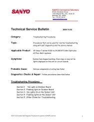
3-7. Taping the Tubes<br />
(1) At this time, the 2 refrigerant tubes (and electrical wire<br />
if local codes permit) should be taped together with<br />
armoring tape. The drain hose may also be included<br />
and taped together as 1 bundle with the tubing.<br />
(2) Wrap the armoring tape from the bottom of the outdoor<br />
unit to the top of the tubing where it enters the wall. As<br />
you wrap the tubing, overlap half of each previous tape<br />
turn. (Fig. 18)<br />
(3) Clamp the tubing bundle to wall, using 1 clamp approx.<br />
every 47" (120 cm).<br />
NOTE<br />
CAUTION<br />
Do not wind the armoring tape too tightly, since this will<br />
decrease the heat insulation effect. Also, be sure the condensation<br />
drain hose splits away from the bundle and drips<br />
clear of the unit and the tubing.<br />
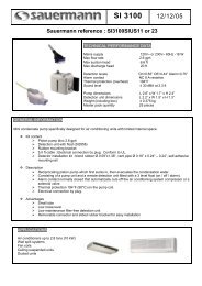
3-8. Finishing the Installation<br />
4. Air Purging<br />
After a tube has been insulated,<br />
never try to bend it into a narrow<br />
curve, as this may cause the tube<br />
to break or crack.<br />
After finishing insulating and taping over the tubing, use<br />
sealing putty to seal off the hole in the wall to prevent rain<br />
and draft from entering. (Fig. 19)<br />
Air and moisture remaining in the refrigerant <strong>system</strong> have<br />
undesirable effects as indicated below. Therefore, they<br />
must be purged completely.<br />
pressure in the <strong>system</strong> rises<br />
operating current rises<br />
cooling efficiency drops<br />
moisture in the <strong>air</strong> may freeze and block capillary tubing<br />
water may lead to corrosion of parts in the refrigerant<br />
<strong>system</strong><br />
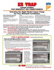
Air Purging with a Vacuum Pump<br />
(for Test Run)<br />
In order to protect the earth’s environment, be sure to use<br />
a vacuum pump to perform the <strong>air</strong> purge.<br />
(Never perform an <strong>air</strong> purge by using the refrigerant gas<br />
cylinder or other external gas, or by using the gas inside<br />
the outdoor unit.)<br />
Service<br />
valve on<br />
narrow<br />
tube side<br />
Service<br />
valve on<br />
wide tube<br />
side<br />
With push-pin<br />
19<br />
D<br />
C<br />
B<br />
A<br />
CAUTION<br />
Apply putty here<br />
Hex wrench<br />
Fig. 18<br />
Fig. 19<br />
Fig. 20<br />
Tubing<br />
Low-pressure<br />
valve<br />
Leave the<br />
valve open.<br />
Open<br />
Charging hose<br />
(special for R410A)<br />
Insulated tubes<br />
Manifold gauge<br />
(special for R410A)<br />
Lo<br />
High-pressure valve<br />
Vacuum pump<br />
adapter<br />
Hi (for preventing<br />
reverse flow)<br />
(special for<br />
R410A)<br />
Vacuum<br />
pump<br />
Clamp<br />
In order to prevent charging errors<br />
with the <strong>air</strong> conditioner that uses<br />
R410A, the screw diameter at the<br />
<strong>service</strong> valve charging port has<br />
been changed. When recharging or<br />
performing other servicing, use the<br />
special charging hose and manifold<br />
gauge.