technical & service manual dc inverter multi-system air ... - Panasonic
technical & service manual dc inverter multi-system air ... - Panasonic
technical & service manual dc inverter multi-system air ... - Panasonic

You also want an ePaper? Increase the reach of your titles
YUMPU automatically turns print PDFs into web optimized ePapers that Google loves.
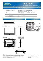
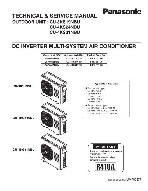
TECHNICAL & SERVICE MANUAL<br />
OUTDOOR UNIT : CU-3KS19NBU<br />
CU-4KS24NBU<br />
CU-4KS31NBU<br />
DC INVERTER MULTI-SYSTEM AIR CONDITIONER<br />
CU-3KS19NBU<br />
CU-4KS24NBU<br />
CU-4KS31NBU<br />
Capacity at 230V<br />
19,700 BTU/h<br />
25,400 BTU/h<br />
30,600 BTU/h<br />
Outdoor Model No.<br />
CU-3KS19NBU<br />
CU-4KS24NBU<br />
CU-4KS31NBU<br />
Product Code No.<br />
1 852 361 24<br />
1 852 361 25<br />
1 852 361 26<br />
< Applicable Indoor Units ><br />
Wall mounted type<br />
CS-MKS7NKU<br />
CS-MKS9NKU<br />
CS-MKS12NKU<br />
CS-MKS18NKU<br />
CS-MKS24NKU<br />
Semi-concealed type<br />
CS-MKS9NB4U & CZ-18BT1U<br />
CS-MKS12NB4U & CZ-18BT1U<br />
CS-KS18NB4UW & CZ-18BT1U<br />
IMPORTANT<br />
These <strong>air</strong> conditioners employ new<br />
refrigerant R410A.<br />
Pay special attention when<br />
servicing the unit.<br />
REFERENCE NO. SM700877
SAFETY PRECAUTIONS<br />
• Before doing rep<strong>air</strong> work, please read the " SAFETY PRECAUTIONS" carefully and fully understand them.<br />
• The precautionary items here are divided into " Warning" and " Caution" items.<br />
Items in particular which may cause death or serious injury to the <strong>service</strong> personnel if the work is not performed correctly,<br />
are included in the " Warning" table.<br />
However, even precautionary items identified as " Caution" also have the potential for serious consequences<br />
if not performed correctly.<br />
Important safety precautions are described for all items in both categories. Be sure to carefully follow all of them.<br />
• Symbol Indication<br />
: This symbol indicates items to which we need to pay attention.<br />
In this triangle, a definite precautionary item is described.<br />
: This symbol indicates the item to be prohibited.<br />
In or close to this circle, a prohibited item is described.<br />
: This symbol indicates the items requiring special attention or instruction.<br />
In or close to this circle, a prohibited item is described.<br />
• After doing rep<strong>air</strong> work, perform a test run to confirm that there are no abnormalities.<br />
At the same time, explain the precautions in use to the user.<br />
Warning<br />
Before performing an overhaul, disconnect the power plug or power cable from the unit.<br />
Performing the work with the power supplied to the unit, may cause an electric shock.<br />
When rep<strong>air</strong> work or circuit inspection that requires power supply for the <strong>air</strong> conditioner, is to be performed,<br />
do not touch the charging section.<br />
Doing so may cause an electric shock.<br />
For the step-up capacitor attached to the electric section, perform the rep<strong>air</strong> work after sufficiently discharging it.<br />
Insufficient capacitor discharge may cause an electric shock.<br />
Do not perform rep<strong>air</strong> work on the electric sections with wet hands.<br />
Doing so may cause an electric shock.<br />
Do not start or stop the <strong>air</strong> conditioner by means of connecting or disconnecting the power plug.<br />
Doing so may cause an electric shock or fire.<br />
When conducting rep<strong>air</strong> work only use components included in the parts list for the corresponding unit and perform<br />
the work with the appropriate tools.<br />
Incorrect or poor rep<strong>air</strong> work may cause an electric shock or fire.<br />
Never modify the unit.<br />
Doing so may cause an electric shock or fire.<br />
Perform all electric work according to local applicable regulations related to electrical equipment or interior wiring<br />
regulation and make sure to use the exclusive circuit.<br />
Insufficient capacity to the electric circuit or defective arrangement results may cause an electric shock or fire.<br />
Make sure to replace any power cable or lead wire showing any signs of scratch or deterioration.<br />
Failure to do so may cause an electric shock, overheating or fire.<br />
Make sure that there is no dust on or slack in the power plug and insert fully into the socket.<br />
Dust or incomplete connections may cause an electric shock or fire.<br />
Do not damage or process the power cord, as it may cause an electric shock or fire.<br />
For the wiring between the indoor unit and outdoor unit, securely fix the specified cable onto the terminal plate.<br />
Poorly fixed wiring may cause a heat or fire.<br />
After connecting the wiring between the indoor unit and outdoor unit, attach the terminal cover securely.<br />
Incomplete attachment of the terminal cover may cause overheating or fire.<br />
2<br />
Prohibit<br />
Prohibit<br />
Prohibit<br />
Prohibit<br />
Prohibit
Warning<br />
If refrigerant gas blows off during the work, do not touch the refrigerant gas as it may cause frostbite.<br />
If refrigerant gas leaks during the work, ventilate the room.<br />
If refrigerant gas catches fire, harmful gas may be generated.<br />
Do not mix any gas other than the specified refrigerant gas in the refrigerating cycle.<br />
If <strong>air</strong> or other contaminants mix with the gas, pressure will become extremely high in the refrigerating cycle,<br />
which may cause a unit breakdown."<br />
When the welded section of the compressor intake or discharge pipe is to be disconnected, perform it in<br />
a well-ventilated place after sufficiently recovering the refrigerant gas.<br />
Any residue gas may jet out refrigerant or refrigerating machine oil, which may cause an injury.<br />
When the work is to be performed in a high place (About 2 meters or more), make sure to wear a safety helmet,<br />
gloves and safety belt. Insufficient safety gear may cause a serious injury in case of a fall.<br />
When the unit is to be relocated, confirm that the new installation location has sufficient strength for the weight of the unit.<br />
Insufficient strength of the installation location and incomplete installation work may cause an injury due to<br />
the unit falling.<br />
When the remote controller batteries are replaced, dispose of the old batteries out of the reach of children.<br />
If a child swallows a battery, make sure that the child gets immediate medical attention.<br />
Caution<br />
Do not wash the <strong>air</strong> conditioner with water, as this may cause an electric shock or fire.<br />
For the rep<strong>air</strong> work in places with high humidity or moisture, make sure to ground the unit.<br />
Failure to do so may cause an electric shock.<br />
Confirm that the component attachment position, wiring condition, soldering condition and connector connection<br />
are normal.<br />
If not, it may cause overheating or fire.<br />
Confirm that the temperature around the compressor is not too high, and then perform the rep<strong>air</strong> work.<br />
Failure to do so may cause a burn.<br />
Perform welding work in a place with good ventilation.<br />
If the work is performed in a poorly ventilated area, it might cause a lack of oxygen.<br />
If the installation plate or attachment frame has deteriorated due to corrosion, etc., replace it.<br />
Failure to do so may cause an injury due to the unit falling.<br />
When the cleaning is to be performed, make sure to turn off the power and pull out the plug.<br />
Touching the fan that is rotating at high speed may result in an injury.<br />
When the indoor unit is to be removed, do not place it on an incline.<br />
Doing so may cause wet furniture because water left inside may trickle down.<br />
Do not hold the sharp end of the unit or the aluminum fins, as it may cause an injury to your hand or finger.<br />
After rep<strong>air</strong>s, make sure to measure the insulation resistance and confirm that the value is 1 Mohm or more.<br />
Any insulation error may cause an electric shock.<br />
After rep<strong>air</strong>s, make sure to check the drainage of the indoor unit.<br />
Inappropriate drainage may cause wet furniture and floors due to water leakage.<br />
3<br />
Prohibit<br />
Prohibit<br />
Prohibit<br />
Prohibit<br />
Prohibit
SAFETY PRECAUTIONS<br />
TABLE OF CONTENTS<br />
Table of Contents<br />
..............................................................................................................<br />
......................................................................................................................<br />
APPLICABLE INDOOR UNITS .....................................................................................................<br />
1. OPERATING RANGE<br />
2. SPECIFICATIONS<br />
2-1. Unit Specifications<br />
2-2. Major Component Specifications<br />
2-3. Other Component Specifications<br />
3. DIMENSIONAL DATA<br />
...................................................................................................................<br />
.............................................................................................................<br />
.......................................................................................<br />
.......................................................................................<br />
...................................................................................................................<br />
4. REFRIGERANT FLOW DIAGRAM<br />
4-1. Refrigerant Flow Diagram ...................................................................................................<br />
5. PERFORMANCE DATA<br />
5-1. Temperature Charts ............................................................................................................<br />
5-2. Cooling Capacity ................................................................................................................<br />
5-3. Cooling Capacity (Low Ambient) ........................................................................................<br />
6. ELECTRICAL DATA<br />
6-1. Electric Wiring Diagrams<br />
....................................................................................................<br />
7. FUNCTIONS<br />
.....................................................................................................<br />
7-1. Explanation of Functions ...........................................................................................................<br />
7-2. Protective Functions<br />
8. TROUBLESHOOTING (BEFORE CALLING FOR SERVICE) ..........................................................<br />
8-1. Precautions before Performing Inspection or .......................................................................<br />
Rep<strong>air</strong><br />
8-2. Trouble Diagnosis by Error Monitop ...........................................................................................<br />
Lamps<br />
8-3. Checking the Outdoor System .........................................................................................<br />
8-4. Trouble Diagnosis of Each Part .........................................................................................<br />
8-5. Trouble Diagnosis of Fan Motor<br />
4<br />
Page<br />
2<br />
4<br />
6<br />
7<br />
8<br />
17<br />
20<br />
21<br />
24<br />
27<br />
50<br />
56<br />
62<br />
65<br />
69<br />
71<br />
72<br />
73<br />
74<br />
78
9. REFRIGERANT R410A:<br />
SPECIAL PRECAUTIONS WHEN SERVICING UNIT<br />
9-1. Characteristics of New Refrigerant R410A .........................................................................<br />
9-2. Checklist before Servicing ...................................................................................................<br />
9-3. Tools Specifically for R410A ................................................................................................<br />
9-4. Tubing Installation Procedures ............................................................................................<br />
9-5. In Case of Compressor Malfunction ....................................................................................<br />
9-6. In Case Refrigerant is Leaking ............................................................................................<br />
9-7. Charging Additional Refrigerant ..........................................................................................<br />
9-8. Retro-Fitting Existing Systems ............................................................................................<br />
APPENDIX A INSTALLATION INSTRUCTIONS<br />
.............................................................................<br />
5<br />
Page<br />
79<br />
80<br />
81<br />
81<br />
82<br />
84<br />
85<br />
85<br />
A-1
APPLICABLE INDOOR UNITS<br />
Wall Mounted Type<br />
Multi-Outdoor Unit<br />
3-Room<br />
4-Room<br />
4-Room<br />
Indoor Unit<br />
CU-3KS19NBU<br />
CU-4KS24NBU<br />
CU-4KS31NBU<br />
Semi-Concealed Type<br />
Multi-Outdoor Unit<br />
3-Room<br />
4-Room<br />
4-Room<br />
Indoor Unit<br />
CU-3KS19NBU<br />
CU-4KS24NBU<br />
CU-4KS31NBU<br />
CS-MKS7NKU<br />
YES<br />
YES<br />
YES<br />
CS-MKS9NB4U<br />
&<br />
CZ-18BT1U<br />
YES<br />
YES<br />
YES<br />
CS-MKS9NKU CS-MKS12NKU CS-MKS18NKU CS-MKS24NKU<br />
YES<br />
YES<br />
YES<br />
CS-MKS12NB4U<br />
&<br />
CZ-18BT1U<br />
YES<br />
YES<br />
YES<br />
6<br />
YES<br />
YES<br />
YES<br />
CS-KS18NB4UW<br />
&<br />
CZ-18BT1U<br />
YES<br />
YES<br />
YES<br />
YES<br />
YES<br />
YES<br />
NO<br />
YES<br />
YES
1. OPERATING RANGE<br />
Cooling<br />
Temperature Indoor Air Intake Temp. Outdoor Air Intake Temp.<br />
Maximum<br />
95 °F DB / 71 °F WB<br />
115 °F DB<br />
Minimum<br />
67 °F DB / 57 °F WB<br />
14 °F DB<br />
7
Outdoor Unit CU-3KS19NBU<br />
Indoor Unit CS-MKS9NKU × 3<br />
Performance<br />
Electrical Rating<br />
Features<br />
Dimensions & Weight<br />
Type<br />
Number of Connectable Indoor Units<br />
Number of Operatable Indoor Units<br />
Voltage Rating<br />
Cooling<br />
Total Capacity<br />
BTU/h<br />
18,800 ( 9,800 to 18,800 )<br />
kW<br />
5.50 ( 2.90 to 5.50 )<br />
Sensible Capacity<br />
BTU/h<br />
16,000<br />
Latent Capacity<br />
BTU/h<br />
2,800<br />
Air Circulation (High) ft 1,707 (2,900)<br />
Available Voltage Range<br />
V<br />
187 to 253<br />
Running Amperes<br />
A<br />
7.4<br />
Power Input<br />
W<br />
1,500<br />
Power Factor %<br />
98<br />
Compressor Locked Rotor Amperes<br />
A 13.0<br />
3 /min (m3 /h)<br />
EER BTU/h/W 12.5<br />
Fuse or Circuit Breaker Capacity A 15<br />
Unit Dimensions<br />
Height × Width × Depth<br />
Package Dimensions<br />
Height × Width × Depth<br />
Weight<br />
Net<br />
Shipping<br />
Shipping Volume<br />
Ibs (kg)<br />
Ibs (kg)<br />
cu.ft (m3 inch<br />
(mm)<br />
inch<br />
(mm)<br />
)<br />
3-Room Multi Outdoor Unit<br />
3<br />
Control<br />
Outdoor Unit<br />
Microprocessor<br />
Fan Speeds Auto (Hi, Me, Lo)<br />
Compressor<br />
DC Twin Rotary (Inverter)<br />
Refrigerant / Amount charged at shipment Ibs (g)<br />
R410A / 6.17 (2,800)<br />
Refrigerant Control<br />
Electric Expansion Valve<br />
Operation Sound (High) Cool<br />
dB-A<br />
50<br />
Refrigerant Tubing Connections<br />
Flare Type<br />
Max. allowable tubing length per unit<br />
ft (m)<br />
82 (25)<br />
Refrigerant Narrow tube inch (mm)<br />
1/4 (6.35) × 3<br />
Tube Diameter Wide tube<br />
inch (mm)<br />
3/8 (9.52) × 3<br />
Outdoor Unit<br />
29-1/8 × 35-7/16 × 12-19/32<br />
(740 × 900 × 320)<br />
34-3/16 × 41-11/32 × 16-21/32<br />
(868 × 1,050 × 423)<br />
138.9 (63.0)<br />
147.7 (67.0)<br />
13.41 (0.38)<br />
< 208V ><br />
DATA SUBJECT TO CHANGE WITHOUT NOTICE.<br />
Remarks:<br />
1. The values shown in performance section and electrical rating section above are based on the following unit combination.<br />
For other combination unit, please refer to the "Unit Combination Tables" in this <strong>manual</strong>.<br />
Indoor Unit : CS-MKS9NKU 3units Outdoor Unit : CU-3KS19NBU 1unit<br />
2. Rating conditions are: Cooling : Indoor <strong>air</strong> temp. 80 °F DB / 67 °F WB<br />
Outdoor <strong>air</strong> temp. 95 °F DB / 75 °F WB<br />
10<br />
3<br />
208V Single-Phase 60Hz
Outdoor Unit CU-4KS24NBU<br />
Indoor Unit CS-MKS7NKU + CS-MKS9NKU × 2<br />
Duct Less Type Rated<br />
Performance<br />
Electrical Rating<br />
Features<br />
Dimensions & Weight<br />
Type<br />
Number of Connectable Indoor Units<br />
Number of Operatable Indoor Units<br />
Voltage Rating<br />
Cooling<br />
Total Capacity<br />
BTU/h<br />
24,200 ( 9,800 to 25,400 )<br />
kW<br />
7.10 ( 2.90 to 7.50 )<br />
Sensible Capacity<br />
BTU/h<br />
20,300<br />
Latent Capacity<br />
BTU/h<br />
3,900<br />
Air Circulation (High) ft 1,707 (2,900)<br />
Available Voltage Range<br />
V<br />
187 to 253<br />
Running Amperes<br />
A<br />
10.7<br />
Power Input<br />
W<br />
2,420<br />
Power Factor %<br />
98<br />
SEER BTU/Wh 18.0<br />
Compressor Locked Rotor Amperes<br />
A 13.0<br />
3 /min (m3 /h)<br />
EER BTU/h/W 10.0<br />
Fuse or Circuit Breaker Capacity A 20<br />
Unit Dimensions<br />
Height × Width × Depth<br />
Package Dimensions<br />
Height × Width × Depth<br />
Weight<br />
Net<br />
Shipping<br />
inch<br />
(mm)<br />
inch<br />
(mm)<br />
Ibs (kg)<br />
Ibs (kg)<br />
4-Room Multi Outdoor Unit<br />
Control<br />
Outdoor Unit<br />
Microprocessor<br />
Fan Speeds Auto (Hi, Me, Lo)<br />
Compressor<br />
DC Twin Rotary (Inverter)<br />
Refrigerant / Amount charged at shipment Ibs (g)<br />
R410A / 6.17 (2,800)<br />
Refrigerant Control<br />
Electric Expansion Valve<br />
Operation Sound (High) Cool<br />
dB-A<br />
50<br />
Refrigerant Tubing Connections<br />
Flare Type<br />
Max. allowable tubing length per unit<br />
ft (m)<br />
82 (25)<br />
Refrigerant Narrow tube inch (mm)<br />
1/4 (6.35) × 4<br />
Tube Diameter Wide tube<br />
inch (mm)<br />
3/8 (9.52) × 3 + 1/2 (12.7) × 1<br />
Outdoor Unit<br />
29-1/8 × 35-7/16 × 12-19/32<br />
(740 × 900 × 320)<br />
34-3/16 × 41-11/32 × 16-21/32<br />
(868 × 1,050 × 423)<br />
138.9 (63.0)<br />
147.7 (67.0)<br />
< 230V ><br />
Shipping Volume<br />
Remarks:<br />
cu.ft (m<br />
DATA SUBJECT TO CHANGE WITHOUT NOTICE.<br />
1. The values shown in performance section and electrical rating section above are based on the following unit combination.<br />
For other combination unit, please refer to the "Unit Combination Tables" in this <strong>manual</strong>.<br />
Indoor Unit : CS-MKE7NKU 1units / CS-MKE9NKU 2units Outdoor Unit : CU-4KS24NBU 1unit<br />
The combination indoor unit is AHRI 210/240.<br />
2. Rating conditions are: Cooling : Indoor <strong>air</strong> temp. 80 °F DB / 67 °F WB<br />
Outdoor <strong>air</strong> temp. 95 °F DB / 75 °F WB<br />
3 )<br />
13.41 (0.38)<br />
11<br />
4<br />
4<br />
230V Single-Phase 60Hz
Outdoor Unit CU-4KS24NBU<br />
Indoor Unit CS-MKS9NKU × 3<br />
Performance<br />
Electrical Rating<br />
Features<br />
Dimensions & Weight<br />
Type<br />
Number of Connectable Indoor Units<br />
Number of Operatable Indoor Units<br />
Voltage Rating<br />
Cooling<br />
Total Capacity<br />
BTU/h<br />
25,400 ( 9,800 to 25,400 )<br />
kW<br />
7.50 ( 2.90 to 7.50 )<br />
Sensible Capacity<br />
BTU/h<br />
21,400<br />
Latent Capacity<br />
BTU/h<br />
4,000<br />
Air Circulation (High) ft 1,707 (2,900)<br />
Available Voltage Range<br />
V<br />
187 to 253<br />
Running Amperes<br />
A<br />
11.3<br />
Power Input<br />
W<br />
2,560<br />
Power Factor %<br />
98<br />
Compressor Locked Rotor Amperes<br />
A 13.0<br />
3 /min (m3 /h)<br />
EER BTU/h/W 9.9<br />
Fuse or Circuit Breaker Capacity A 20<br />
Unit Dimensions<br />
Height × Width × Depth<br />
Package Dimensions<br />
Height × Width × Depth<br />
Weight<br />
Net<br />
Shipping<br />
Shipping Volume<br />
Ibs (kg)<br />
Ibs (kg)<br />
cu.ft (m3 inch<br />
(mm)<br />
inch<br />
(mm)<br />
)<br />
4-Room Multi Outdoor Unit<br />
4<br />
Control<br />
Outdoor Unit<br />
Microprocessor<br />
Fan Speeds Auto (Hi, Me, Lo)<br />
Compressor<br />
DC Twin Rotary (Inverter)<br />
Refrigerant / Amount charged at shipment Ibs (g)<br />
R410A / 6.17 (2,800)<br />
Refrigerant Control<br />
Electric Expansion Valve<br />
Operation Sound (High) Cool<br />
dB-A<br />
50<br />
Refrigerant Tubing Connections<br />
Flare Type<br />
Max. allowable tubing length per unit<br />
ft (m)<br />
82 (25)<br />
Refrigerant Narrow tube inch (mm)<br />
1/4 (6.35) × 4<br />
Tube Diameter Wide tube<br />
inch (mm)<br />
3/8 (9.52) × 3 + 1/2 (12.7) × 1<br />
Outdoor Unit<br />
29-1/8 × 35-7/16 × 12-19/32<br />
(740 × 900 × 320)<br />
34-3/16 × 41-11/32 × 16-21/32<br />
(868 × 1,050 × 423)<br />
138.9 (63.0)<br />
147.7 (67.0)<br />
13.41 (0.38)<br />
< 230V ><br />
DATA SUBJECT TO CHANGE WITHOUT NOTICE.<br />
Remarks:<br />
1. The values shown in performance section and electrical rating section above are based on the following unit combination.<br />
For other combination unit, please refer to the "Unit Combination Tables" in this <strong>manual</strong>.<br />
Indoor Unit : CS-MKS9NKU 3units Outdoor Unit : CU-4KS24NBU 1unit<br />
2. Rating conditions are: Cooling : Indoor <strong>air</strong> temp. 80 °F DB / 67 °F WB<br />
Outdoor <strong>air</strong> temp. 95 °F DB / 75 °F WB<br />
12<br />
4<br />
230V Single-Phase 60Hz
Outdoor Unit CU-4KS24NBU<br />
Indoor Unit CS-MKS9NKU × 3<br />
Performance<br />
Electrical Rating<br />
Features<br />
Dimensions & Weight<br />
Type<br />
Number of Connectable Indoor Units<br />
Number of Operatable Indoor Units<br />
Voltage Rating<br />
Cooling<br />
Total Capacity<br />
BTU/h<br />
24,400 ( 9,800 to 24,400 )<br />
kW<br />
7.20 ( 2.90 to 7.20 )<br />
Sensible Capacity<br />
BTU/h<br />
20,600<br />
Latent Capacity<br />
BTU/h<br />
3,800<br />
Air Circulation (High) ft 1,707 (2,900)<br />
Available Voltage Range<br />
V<br />
187 to 253<br />
Running Amperes<br />
A<br />
12.1<br />
Power Input<br />
W<br />
2,460<br />
Power Factor %<br />
98<br />
Compressor Locked Rotor Amperes<br />
A 13.0<br />
3 /min (m3 /h)<br />
EER BTU/h/W 9.9<br />
Fuse or Circuit Breaker Capacity A 20<br />
Unit Dimensions<br />
Height × Width × Depth<br />
Package Dimensions<br />
Height × Width × Depth<br />
Weight<br />
Net<br />
Shipping<br />
Shipping Volume<br />
Ibs (kg)<br />
Ibs (kg)<br />
cu.ft (m3 inch<br />
(mm)<br />
inch<br />
(mm)<br />
)<br />
4-Room Multi Outdoor Unit<br />
4<br />
Control<br />
Outdoor Unit<br />
Microprocessor<br />
Fan Speeds Auto (Hi, Me, Lo)<br />
Compressor<br />
DC Twin Rotary (Inverter)<br />
Refrigerant / Amount charged at shipment Ibs (g)<br />
R410A / 6.17 (2,800)<br />
Refrigerant Control<br />
Electric Expansion Valve<br />
Operation Sound (High) Cool<br />
dB-A<br />
50<br />
Refrigerant Tubing Connections<br />
Flare Type<br />
Max. allowable tubing length per unit<br />
ft (m)<br />
82 (25)<br />
Refrigerant Narrow tube inch (mm)<br />
1/4 (6.35) × 4<br />
Tube Diameter Wide tube<br />
inch (mm)<br />
3/8 (9.52) × 3 + 1/2 (12.7) × 1<br />
Outdoor Unit<br />
29-1/8 × 35-7/16 × 12-19/32<br />
(740 × 900 × 320)<br />
34-3/16 × 41-11/32 × 16-21/32<br />
(868 × 1,050 × 423)<br />
138.9 (63.0)<br />
147.7 (67.0)<br />
13.41 (0.38)<br />
< 208V ><br />
DATA SUBJECT TO CHANGE WITHOUT NOTICE.<br />
Remarks:<br />
1. The values shown in performance section and electrical rating section above are based on the following unit combination.<br />
For other combination unit, please refer to the "Unit Combination Tables" in this <strong>manual</strong>.<br />
Indoor Unit : CS-MKS9NKU 3units Outdoor Unit : CU-4KS24NBU 1unit<br />
2. Rating conditions are: Cooling : Indoor <strong>air</strong> temp. 80 °F DB / 67 °F WB<br />
Outdoor <strong>air</strong> temp. 95 °F DB / 75 °F WB<br />
13<br />
4<br />
208V Single-Phase 60Hz
Outdoor Unit CU-4KS31NBU<br />
Indoor Unit CS-MKS7NKU × 3 + CS-MKS9NKU<br />
Duct Less Type Rated<br />
Performance<br />
Electrical Rating<br />
Features<br />
Dimensions & Weight<br />
Type<br />
Number of Connectable Indoor Units<br />
Number of Operatable Indoor Units<br />
Voltage Rating<br />
Cooling<br />
Total Capacity<br />
BTU/h<br />
29,000 ( 9,800 to 29,000 )<br />
kW<br />
8.50 ( 2.90 to 8.50 )<br />
Sensible Capacity<br />
BTU/h<br />
24,400<br />
Latent Capacity<br />
BTU/h<br />
4,600<br />
Air Circulation (High) ft 1,942 (3,300)<br />
Available Voltage Range<br />
V<br />
187 to 253<br />
Running Amperes<br />
A<br />
11.4<br />
Power Input<br />
W<br />
2,600<br />
Power Factor %<br />
99<br />
SEER BTU/Wh 17.6<br />
Compressor Locked Rotor Amperes<br />
A 17.0<br />
3 /min (m3 /h)<br />
EER BTU/h/W 11.2<br />
Fuse or Circuit Breaker Capacity A 20<br />
Unit Dimensions<br />
Height × Width × Depth<br />
Package Dimensions<br />
Height × Width × Depth<br />
Weight<br />
Net<br />
Shipping<br />
inch<br />
(mm)<br />
inch<br />
(mm)<br />
Ibs (kg)<br />
Ibs (kg)<br />
4-Room Multi Outdoor Unit<br />
Control<br />
Outdoor Unit<br />
Microprocessor<br />
Fan Speeds Auto (Hi, Me, Lo)<br />
Compressor<br />
DC Twin Rotary (Inverter)<br />
Refrigerant / Amount charged at shipment Ibs (g)<br />
R410A / 8.38 (3,800)<br />
Refrigerant Control<br />
Electric Expansion Valve<br />
Operation Sound (High) Cool<br />
dB-A<br />
53<br />
Refrigerant Tubing Connections<br />
Flare Type<br />
Max. allowable tubing length per unit<br />
ft (m)<br />
100 (30.5)<br />
Refrigerant Narrow tube inch (mm)<br />
1/4 (6.35) × 4<br />
Tube Diameter Wide tube<br />
inch (mm)<br />
3/8 (9.52) × 2 + 1/2 (12.7) × 2<br />
Outdoor Unit<br />
35-1/32 × 35-7/16 × 12-19/32<br />
(890 × 900 × 320)<br />
40-1/8 × 41-11/32 × 16-21/32<br />
(1,019 × 1,050 × 423)<br />
174.2 (79.0)<br />
183.0 (83.0)<br />
< 230V ><br />
Shipping Volume<br />
Remarks:<br />
cu.ft (m<br />
DATA SUBJECT TO CHANGE WITHOUT NOTICE.<br />
1. The values shown in performance section and electrical rating section above are based on the following unit combination.<br />
For other combination unit, please refer to the "Unit Combination Tables" in this <strong>manual</strong>.<br />
Indoor Unit : CS-MKE7NKU 3units / CS-MKE9NKU 1units Outdoor Unit : CU-4KS31NBU 1unit<br />
The combination indoor unit is AHRI 210/240.<br />
2. Rating conditions are: Cooling : Indoor <strong>air</strong> temp. 80 °F DB / 67 °F WB<br />
Outdoor <strong>air</strong> temp. 95 °F DB / 75 °F WB<br />
3 )<br />
15.88 (0.45)<br />
14<br />
4<br />
4<br />
230V Single-Phase 60Hz
Outdoor Unit CU-4KS31NBU<br />
Indoor Unit CS-MKS9NKU × 4<br />
Performance<br />
Electrical Rating<br />
Features<br />
Dimensions & Weight<br />
Type<br />
Number of Connectable Indoor Units<br />
Number of Operatable Indoor Units<br />
Voltage Rating<br />
Cooling<br />
Total Capacity<br />
BTU/h<br />
30,600 ( 9,800 to 30,600 )<br />
kW<br />
9.00 ( 2.90 to 9.00 )<br />
Sensible Capacity<br />
BTU/h<br />
25,800<br />
Latent Capacity<br />
BTU/h<br />
4,800<br />
Air Circulation (High) ft 1,942 (3,300)<br />
Available Voltage Range<br />
V<br />
187 to 253<br />
Running Amperes<br />
A<br />
12.3<br />
Power Input<br />
W<br />
2,800<br />
Power Factor %<br />
99<br />
Compressor Locked Rotor Amperes<br />
A 17.0<br />
3 /min (m3 /h)<br />
EER BTU/h/W 10.9<br />
Fuse or Circuit Breaker Capacity A 20<br />
Unit Dimensions<br />
Height × Width × Depth<br />
Package Dimensions<br />
Height × Width × Depth<br />
Weight<br />
Net<br />
Shipping<br />
Shipping Volume<br />
Ibs (kg)<br />
Ibs (kg)<br />
cu.ft (m3 inch<br />
(mm)<br />
inch<br />
(mm)<br />
)<br />
4-Room Multi Outdoor Unit<br />
4<br />
Control<br />
Outdoor Unit<br />
Microprocessor<br />
Fan Speeds Auto (Hi, Me, Lo)<br />
Compressor<br />
DC Twin Rotary (Inverter)<br />
Refrigerant / Amount charged at shipment Ibs (g)<br />
R410A / 8.38 (3,800)<br />
Refrigerant Control<br />
Electric Expansion Valve<br />
Operation Sound (High) Cool<br />
dB-A<br />
53<br />
Refrigerant Tubing Connections<br />
Flare Type<br />
Max. allowable tubing length per unit<br />
ft (m)<br />
100 (30.5)<br />
Refrigerant Narrow tube inch (mm)<br />
1/4 (6.35) × 4<br />
Tube Diameter Wide tube<br />
inch (mm)<br />
3/8 (9.52) × 2 + 1/2 (12.7) × 2<br />
Outdoor Unit<br />
35-1/32 × 35-7/16 × 12-19/32<br />
(890 × 900 × 320)<br />
40-1/8 × 41-11/32 × 16-21/32<br />
(1,019 × 1,050 × 423)<br />
174.2 (79.0)<br />
183.0 (83.0)<br />
15.88 (0.45)<br />
< 230V ><br />
DATA SUBJECT TO CHANGE WITHOUT NOTICE.<br />
Remarks:<br />
1. The values shown in performance section and electrical rating section above are based on the following unit combination.<br />
For other combination unit, please refer to the "Unit Combination Tables" in this <strong>manual</strong>.<br />
Indoor Unit : CS-MKS9NKU 4units Outdoor Unit : CU-4KS31NBU 1unit<br />
2. Rating conditions are: Cooling : Indoor <strong>air</strong> temp. 80 °F DB / 67 °F WB<br />
Outdoor <strong>air</strong> temp. 95 °F DB / 75 °F WB<br />
15<br />
4<br />
230V Single-Phase 60Hz
Outdoor Unit CU-4KS31NBU<br />
Indoor Unit CS-MKS9NKU × 4<br />
Performance<br />
Electrical Rating<br />
Features<br />
Dimensions & Weight<br />
Type<br />
Number of Connectable Indoor Units<br />
Number of Operatable Indoor Units<br />
Voltage Rating<br />
Cooling<br />
Total Capacity<br />
BTU/h<br />
28,600 ( 9,800 to 28,600 )<br />
kW<br />
8.40 ( 2.90 to 8.40 )<br />
Sensible Capacity<br />
BTU/h<br />
24,200<br />
Latent Capacity<br />
BTU/h<br />
4,400<br />
Air Circulation (High) ft 1,942 (3,300)<br />
Available Voltage Range<br />
V<br />
187 to 253<br />
Running Amperes<br />
A<br />
12.7<br />
Power Input<br />
W<br />
2,560<br />
Power Factor %<br />
99<br />
Compressor Locked Rotor Amperes<br />
A 17.0<br />
3 /min (m3 /h)<br />
EER BTU/h/W 11.2<br />
Fuse or Circuit Breaker Capacity A 20<br />
Unit Dimensions<br />
Height × Width × Depth<br />
Package Dimensions<br />
Height × Width × Depth<br />
Weight<br />
Net<br />
Shipping<br />
Shipping Volume<br />
Ibs (kg)<br />
Ibs (kg)<br />
cu.ft (m3 inch<br />
(mm)<br />
inch<br />
(mm)<br />
)<br />
4-Room Multi Outdoor Unit<br />
4<br />
Control<br />
Outdoor Unit<br />
Microprocessor<br />
Fan Speeds Auto (Hi, Me, Lo)<br />
Compressor<br />
DC Twin Rotary (Inverter)<br />
Refrigerant / Amount charged at shipment Ibs (g)<br />
R410A / 8.38 (3,800)<br />
Refrigerant Control<br />
Electric Expansion Valve<br />
Operation Sound (High) Cool<br />
dB-A<br />
53<br />
Refrigerant Tubing Connections<br />
Flare Type<br />
Max. allowable tubing length per unit<br />
ft (m)<br />
100 (30.5)<br />
Refrigerant Narrow tube inch (mm)<br />
1/4 (6.35) × 4<br />
Tube Diameter Wide tube<br />
inch (mm)<br />
3/8 (9.52) × 2 + 1/2 (12.7) × 2<br />
Outdoor Unit<br />
35-1/32 × 35-7/16 × 12-19/32<br />
(890 × 900 × 320)<br />
40-1/8 × 41-11/32 × 16-21/32<br />
(1,019 × 1,050 × 423)<br />
174.2 (79.0)<br />
183.0 (83.0)<br />
15.88 (0.45)<br />
< 208V ><br />
DATA SUBJECT TO CHANGE WITHOUT NOTICE.<br />
Remarks:<br />
1. The values shown in performance section and electrical rating section above are based on the following unit combination.<br />
For other combination unit, please refer to the "Unit Combination Tables" in this <strong>manual</strong>.<br />
Indoor Unit : CS-MKS9NKU 4units Outdoor Unit : CU-4KS31NBU 1unit<br />
2. Rating conditions are: Cooling : Indoor <strong>air</strong> temp. 80 °F DB / 67 °F WB<br />
Outdoor <strong>air</strong> temp. 95 °F DB / 75 °F WB<br />
16<br />
4<br />
208V Single-Phase 60Hz
2-2. Major Component Specifications<br />
2-2-1. Outdoor Unit<br />
Outdoor Unit CU-3KS19NBU<br />
Control PCB<br />
Part No.<br />
Controls<br />
Control Circuit Fuse<br />
Compressor<br />
Type<br />
Compressor Model / Nominal Output<br />
Compressor Oil ... Amount<br />
Pints (cc)<br />
Coil Resistance (Ambient Temp. 68 °F (20 °C)) Ohm<br />
Safety Device<br />
CT (Peak current cut-off control)<br />
Compressor Discharge Temp. Control<br />
Operation cut-off control in abnormal ambient Temp.<br />
Model<br />
Heat Exchanger Coil<br />
Coil<br />
Rows<br />
Fins per inch<br />
W<br />
Ohm<br />
Micro F<br />
VAC<br />
CB-CU-3KS19NBU<br />
Microprocessor<br />
250V 25A<br />
DC Twin Rotary (Hermetic)<br />
5KD240XAB21 / 1,700W<br />
FV50S ... 1.91 (900)<br />
U - V : 0.720<br />
V - W : 0.708<br />
W - U : 0.726<br />
Overload Relay CS-7L-2515<br />
Operation Temp. Open : 239 °F (115 °C), Close : 212 °F (100 °C)<br />
Run Capacitor<br />
Micro F<br />
-<br />
VAC<br />
-<br />
Crankcase Heater<br />
230V 30W<br />
Fan<br />
Type<br />
Q'ty ... Dia. inch (mm)<br />
Fan Motor<br />
Type<br />
Model ... Q'ty<br />
No. of Poles<br />
Rough Measure RPM (Cool)<br />
Nominal Output<br />
Coil Resistance<br />
(Ambient Temp. 68 °F (20 °C))<br />
Safety Device<br />
Type<br />
Over-Current Protection<br />
Over-Heat Protection<br />
Run Capacitor<br />
DC Motor<br />
SIC-71FW-D490-1 ... 1<br />
External Finish Acrylic baked-on enamel finish<br />
Yes<br />
Yes<br />
Yes<br />
Propeller<br />
1 ... D18-1/8 (D460)<br />
8<br />
750<br />
90<br />
-<br />
Internal Controller<br />
Yes<br />
Yes<br />
-<br />
-<br />
Aluminum Plate Fin / Copper Tube<br />
2<br />
18.1<br />
Face Area ft 2 (m 2 ) 6.40 (0.595)<br />
17<br />
DATA SUBJECT TO CHANGE WITHOUT NOTICE.
Outdoor Unit CU-4KS24NBU<br />
Control PCB<br />
Part No.<br />
Controls<br />
Control Circuit Fuse<br />
Compressor<br />
Type<br />
Compressor Model / Nominal Output<br />
Compressor Oil ... Amount<br />
Pints (cc)<br />
Coil Resistance (Ambient Temp. 68 °F (20 °C)) Ohm<br />
Safety Device<br />
CT (Peak current cut-off control)<br />
Compressor Discharge Temp. Control<br />
Operation cut-off control in abnormal ambient Temp.<br />
Model<br />
Heat Exchanger Coil<br />
Coil<br />
Rows<br />
Fins per inch<br />
W<br />
Ohm<br />
Micro F<br />
VAC<br />
CB-CU-4KS24NBU<br />
Microprocessor<br />
250V 25A<br />
DC Twin Rotary (Hermetic)<br />
5KD240XAB21 / 1,700W<br />
FV50S ... 1.91 (900)<br />
U - V : 0.720<br />
V - W : 0.708<br />
W - U : 0.726<br />
Overload Relay CS-7L-2515<br />
Operation Temp. Open : 239 °F (115 °C), Close : 212 °F (100 °C)<br />
Run Capacitor<br />
Micro F<br />
-<br />
VAC<br />
-<br />
Crankcase Heater<br />
230V 30W<br />
Fan<br />
Type<br />
Q'ty ... Dia. inch (mm)<br />
Fan Motor<br />
Type<br />
Model ... Q'ty<br />
No. of Poles<br />
Rough Measure RPM (Cool)<br />
Nominal Output<br />
Coil Resistance<br />
(Ambient Temp. 68 °F (20 °C))<br />
Safety Device<br />
Type<br />
Over-Current Protection<br />
Over-Heat Protection<br />
Run Capacitor<br />
DC Motor<br />
SIC-71FW-D490-1 ... 1<br />
External Finish Acrylic baked-on enamel finish<br />
Yes<br />
Yes<br />
Yes<br />
Propeller<br />
1 ... D18-1/8 (D460)<br />
8<br />
750<br />
90<br />
-<br />
Internal Controller<br />
Yes<br />
Yes<br />
-<br />
-<br />
Aluminum Plate Fin / Copper Tube<br />
2<br />
18.1<br />
Face Area ft 2 (m 2 ) 6.40 (0.595)<br />
18<br />
DATA SUBJECT TO CHANGE WITHOUT NOTICE.
Outdoor Unit CU-4KS31NBU<br />
Control PCB<br />
Part No.<br />
Controls<br />
Control Circuit Fuse<br />
Compressor<br />
Type<br />
Compressor Model / Nominal Output<br />
Compressor Oil ... Amount<br />
Pints (cc)<br />
Coil Resistance (Ambient Temp. 68 °F (20 °C)) Ohm<br />
Safety Device<br />
CT (Peak current cut-off control)<br />
Compressor Discharge Temp. Control<br />
Operation cut-off control in abnormal ambient Temp.<br />
Model<br />
Heat Exchanger Coil<br />
Coil<br />
Rows<br />
Fins per inch<br />
W<br />
Ohm<br />
Micro F<br />
VAC<br />
CB-CU-4KS31NBU<br />
Microprocessor<br />
250V 25A<br />
DC Twin Rotary (Hermetic)<br />
5JD420XAB22 / 3,000W<br />
FV50S ... 2.55 (1,200)<br />
U - V : 0.435<br />
V - W : 0.441<br />
W - U : 0.452<br />
Overload Relay CS-7L-2515<br />
Operation Temp. Open : 239 °F (115 °C), Close : 212 °F (100 °C)<br />
Run Capacitor<br />
Micro F<br />
-<br />
VAC<br />
-<br />
Crankcase Heater<br />
230V 30W<br />
Fan<br />
Type<br />
Q'ty ... Dia. inch (mm)<br />
Fan Motor<br />
Type<br />
Model ... Q'ty<br />
No. of Poles<br />
Rough Measure RPM (Cool)<br />
Nominal Output<br />
Coil Resistance<br />
(Ambient Temp. 68 °F (20 °C))<br />
Safety Device<br />
Type<br />
Over-Current Protection<br />
Over-Heat Protection<br />
Run Capacitor<br />
DC Motor<br />
SIC-71FW-D490-1 ... 1<br />
External Finish Acrylic baked-on enamel finish<br />
Yes<br />
Yes<br />
Yes<br />
Propeller<br />
1 ... D18-1/8 (D460)<br />
8<br />
800<br />
90<br />
-<br />
Internal Controller<br />
Yes<br />
Yes<br />
-<br />
-<br />
Aluminum Plate Fin / Copper Tube<br />
2<br />
18.1<br />
Face Area ft 2 (m 2 ) 7.75 (0.72)<br />
19<br />
DATA SUBJECT TO CHANGE WITHOUT NOTICE.
2-3. Other Component Specifications<br />
Sensor Name<br />
Outdoor <strong>air</strong> temp sensor<br />
Outdoor heat exchanger sensor<br />
AW / AN sensor<br />
BW / BN sensor<br />
CW / CN sensor<br />
DW / DN sensor<br />
Sensor Name<br />
Model No.<br />
of sensor<br />
TKS295B<br />
TKS292B<br />
TKS292B<br />
TKS292B<br />
TKS292B<br />
TKS292B<br />
Resistance (k ohm)<br />
Resistance (k ohm)<br />
40<br />
35<br />
30<br />
25<br />
20<br />
15<br />
10<br />
Compressor temp sensor TKS293B<br />
5<br />
0<br />
Model No.<br />
of sensor<br />
200<br />
180<br />
160<br />
140<br />
120<br />
100<br />
80<br />
60<br />
40<br />
20<br />
0<br />
1<br />
1<br />
1 / 1<br />
1 / 1<br />
1 / 1<br />
0<br />
Quantity of Sensor<br />
CU-3KS19NBU CU-4KS24NBU CU-4KS31NBU<br />
1<br />
1<br />
1 / 1<br />
1 / 1<br />
1 / 1<br />
1 / 1<br />
-4 5 14 23 32 41 50 59 68<br />
(-20)(-15)(-10) (-5) (0) (5) (10) (15) (20)<br />
Temperature F ( C)<br />
Quantity of Sensor<br />
CU-3KS19NBU CU-4KS24NBU CU-4KS31NBU<br />
1 1<br />
32 50 68 86 104 122 140 158 176 194<br />
(0) (10) (20) (30) (40) (50) (60) (70) (80) (90)<br />
Temperature F ( C)<br />
20<br />
1<br />
1<br />
1 / 1<br />
1 / 1<br />
1 / 1<br />
1 / 1<br />
1
3. DIMENSIONAL DATA<br />
Outdoor Unit CU-3KS19NBU<br />
1-3/8<br />
11-17/32<br />
ID:23/32<br />
23-15/16 5-11/32<br />
35-7/16(900)<br />
2-ID:15/16<br />
15/32<br />
2-15/16<br />
12-19/32(320)<br />
23/32<br />
1-13/16<br />
2-1/16<br />
21<br />
29-1/8(740)<br />
13-19/32<br />
14-17/32<br />
5-29/32 2-27/32 2-3/4<br />
2-1/32 4-1/2<br />
Wide tube <strong>service</strong> valve<br />
dia.3/8" (9.52) × 3<br />
Narrow tube <strong>service</strong> valve<br />
dia.1/4" (6.35) × 3<br />
2-15/16 2-3/4<br />
4-7/16<br />
Unit: inch(mm)<br />
(852-0-0010-11500-0)
Outdoor Unit CU-4KS24NBU<br />
1-3/8<br />
11-17/32<br />
ID:23/32<br />
23-15/16 5-11/32<br />
35-7/16(900)<br />
2-ID:15/16<br />
15/32<br />
2-15/16<br />
12-19/32(320)<br />
23/32<br />
1-13/16<br />
2-1/16<br />
2-13/32<br />
22<br />
29-1/8(740)<br />
13-19/32<br />
14-17/32<br />
5-29/32 2-27/32 2-3/4 2-3/4<br />
2-1/32 4-1/2<br />
Wide tube <strong>service</strong> valve<br />
dia.1/2" (12.70) × 1<br />
Narrow tube <strong>service</strong> valve<br />
dia.1/4" (6.35) × 4<br />
Wide tube <strong>service</strong> valve<br />
dia.3/8" (9.52) × 3<br />
2-15/16 2-3/4 2-3/4<br />
4-7/16<br />
Unit: inch(mm)<br />
(852-0-0010-20500-0)
Outdoor Unit CU-4KS31NBU<br />
1-3/8<br />
11-17/32<br />
ID:23/32<br />
23-15/16 5-11/32<br />
35-7/16(900)<br />
2-ID:15/16<br />
15/32<br />
2-15/16<br />
12-19/32(320)<br />
23/32<br />
1-13/16<br />
2-1/16<br />
2-13/32<br />
23<br />
35-1/32(890)<br />
13-19/32<br />
14-17/32<br />
2-7/8 2-3/4 2-3/4<br />
5-29/32<br />
2-1/32 4-1/2<br />
Wide tube <strong>service</strong> valve<br />
dia.1/2" (12.70) × 2<br />
Narrow tube <strong>service</strong> valve<br />
dia.1/4" (6.35) × 4<br />
Wide tube <strong>service</strong> valve<br />
dia.3/8" (9.52) × 2<br />
2-15/16 2-3/4 2-3/4<br />
4-7/16<br />
Unit: inch(mm)<br />
(852-0-0010-20600-0)
4. REFRIGERANT FLOW DIAGRAM<br />
4-1. Refrigerant Flow Diagram<br />
Outdoor Unit CU-3KS19NBU<br />
Indoor unit Outdoor unit<br />
Wide tube<br />
O.D.3/8"<br />
O.D.3/8"<br />
O.D.3/8"<br />
Narrow tube<br />
O.D.1/4"<br />
O.D.1/4"<br />
O.D.1/4"<br />
Service valve on<br />
wide tube<br />
CW<br />
Service valve on<br />
narrow tube<br />
CN<br />
Insulation of Refrigerant Tubing<br />
IMPORTANT<br />
BN<br />
AN<br />
BW<br />
AW<br />
Header<br />
M<br />
M<br />
M<br />
Strainer Header<br />
Because capillary tubing is used in the outdoor unit, both the<br />
wide and narrow tubes of this <strong>air</strong> conditioner become cold. To<br />
prevent heat loss and wet floors due to dripping of<br />
condensation, both tubes must be well insulated with a<br />
proper insulation material. The thickness of the insulation<br />
should be a min.5/16"(8 mm).<br />
CAUTION<br />
Electric<br />
expansion<br />
valve<br />
After a tube has been insulated,<br />
never try to bend it into a narrow<br />
curve because it can cause the tube<br />
to break or crack.<br />
24<br />
Sub<br />
accumulator<br />
Thickness:<br />
Min.5/16"(8 mm)<br />
Wide tube<br />
Main<br />
accumulator<br />
High pressure<br />
switch<br />
H.P.<br />
Compressor<br />
Heat exchanger<br />
Insulation<br />
Cooling cycle<br />
Thickness:<br />
Min.5/16"(8 mm)<br />
Narrow tube
Outdoor Unit CU-4KS24NBU<br />
Indoor unit Outdoor unit<br />
Insulation of Refrigerant Tubing<br />
IMPORTANT<br />
Because capillary tubing is used in the outdoor unit, both the<br />
wide and narrow tubes of this <strong>air</strong> conditioner become cold. To<br />
prevent heat loss and wet floors due to dripping of<br />
condensation, both tubes must be well insulated with a<br />
proper insulation material. The thickness of the insulation<br />
should be a min.5/16"(8 mm).<br />
CAUTION<br />
Wide tube<br />
O.D.1/2"<br />
O.D.3/8"<br />
O.D.3/8"<br />
O.D.3/8"<br />
Narrow tube<br />
O.D.1/4"<br />
O.D.1/4"<br />
O.D.1/4"<br />
O.D.1/4"<br />
Service valve on<br />
wide tube<br />
DW<br />
CW<br />
BW<br />
AW<br />
Service valve on<br />
narrow tube<br />
DN<br />
CN<br />
BN<br />
AN<br />
Header<br />
Electric<br />
expansion<br />
valve<br />
M<br />
After a tube has been insulated,<br />
never try to bend it into a narrow<br />
curve because it can cause the tube<br />
to break or crack.<br />
M<br />
M<br />
M<br />
Strainer Header<br />
25<br />
Sub<br />
accumulator<br />
Thickness:<br />
Min.5/16"(8 mm)<br />
Wide tube<br />
Main<br />
accumulator<br />
High pressure<br />
switch<br />
H.P.<br />
Compressor<br />
Heat exchanger<br />
Insulation<br />
Thickness:<br />
Min.5/16"(8 mm)<br />
Narrow tube<br />
Cooling cycle
Outdoor Unit CU-4KS31NBU<br />
Indoor unit Outdoor unit<br />
Wide tube<br />
O.D.1/2"<br />
O.D.1/2"<br />
O.D.3/8"<br />
O.D.3/8"<br />
Narrow tube<br />
O.D.1/4"<br />
O.D.1/4"<br />
O.D.1/4"<br />
O.D.1/4"<br />
Service valve on<br />
wide tube<br />
DW<br />
CW<br />
BW<br />
AW<br />
Service valve on<br />
narrow tube<br />
DN<br />
Insulation of Refrigerant Tubing<br />
IMPORTANT<br />
CN<br />
BN<br />
AN<br />
Header<br />
Electric<br />
expansion<br />
valve<br />
M<br />
M<br />
M<br />
M<br />
Strainer Header<br />
Because capillary tubing is used in the outdoor unit, both the<br />
wide and narrow tubes of this <strong>air</strong> conditioner become cold. To<br />
prevent heat loss and wet floors due to dripping of<br />
condensation, both tubes must be well insulated with a<br />
proper insulation material. The thickness of the insulation<br />
should be a min.5/16"(8 mm).<br />
CAUTION<br />
After a tube has been insulated,<br />
never try to bend it into a narrow<br />
curve because it can cause the tube<br />
to break or crack.<br />
26<br />
Sub<br />
accumulator<br />
Thickness:<br />
Min.5/16"(8 mm)<br />
Wide tube<br />
Main<br />
accumulator<br />
High pressure<br />
switch<br />
H.P.<br />
Compressor<br />
Heat exchanger<br />
Insulation<br />
Cooling cycle<br />
Thickness:<br />
Min.5/16"(8 mm)<br />
Narrow tube
5. PERFORMANCE DATA<br />
5-1. Temperature Charts<br />
5-1-1. Temperature Charts (CU-3KS19NBU)<br />
Outdoor Unit CU-3KS19NBU Indoor Unit CS-MKS7NKU × 1<br />
Cooling Characteristics<br />
(RH : 46%, Indoor fan speed : High fan)<br />
(230V, 60Hz)<br />
(1) Low pressure performance chart<br />
Low pressure at wide tube <strong>service</strong> valve<br />
psig (MPaG)<br />
188<br />
(1.3)<br />
174<br />
(1.2)<br />
160<br />
(1.1)<br />
146<br />
(1.0) 77<br />
(25)<br />
Lo fan Hi fan HH fan<br />
86<br />
(30)<br />
Outdoor <strong>air</strong> temperature °F (°C)<br />
(2) Operating current performance chart<br />
Operating current (A)<br />
5<br />
4<br />
3<br />
2<br />
(3) Indoor discharge <strong>air</strong> performance chart<br />
Indoor discharge <strong>air</strong> temperature °F (°C)<br />
68.0(20)<br />
64.4(18)<br />
60.8(16)<br />
57.2(14)<br />
53.6(12)<br />
50.0(10)<br />
77<br />
(25)<br />
46.4( 8)<br />
77<br />
(25)<br />
NOTE<br />
• This performance chart shows operation of a single wall-mounted indoor unit. The performance chart will vary depending on<br />
the indoor unit type.<br />
• Check each performance value in test-run mode. Electrical performance values represent a combined indoor/outdoor value.<br />
(In this case, be sure to stop all the indoor units where performance is not being checked.)<br />
• The performance is for a tubing length of 24.6t (7.5m). If the tubing length is different, the performance chart will vary.<br />
95<br />
(35)<br />
Outdoor <strong>air</strong> temperature °F (°C)<br />
104<br />
(40)<br />
Lo fan Hi fan HH fan<br />
86<br />
(30)<br />
95<br />
(35)<br />
Lo fan Hi fan HH fan<br />
86<br />
(30)<br />
Indoor <strong>air</strong> temp. 86°F (30°C)<br />
95<br />
(35)<br />
Outdoor <strong>air</strong> temperature °F (°C)<br />
27<br />
80°F (27°C)<br />
75°F (24°C)<br />
Indoor <strong>air</strong> temp. 86°F (30°C)<br />
80°F (27°C)<br />
75°F (24°C)<br />
Indoor <strong>air</strong> temp. 86°F (30°C)<br />
80°F (27°C)<br />
75°F (24°C)<br />
104<br />
(40)<br />
104<br />
(40)
Outdoor Unit CU-3KS19NBU Indoor Unit CS-MKS9NKU × 1<br />
Cooling Characteristics<br />
(RH : 46%, Indoor fan speed : High fan)<br />
(230V, 60Hz)<br />
(1) Low pressure performance chart<br />
Low pressure at wide tube <strong>service</strong> valve<br />
psig (MPaG)<br />
Lo fan Hi fan<br />
Outdoor <strong>air</strong> temperature °F (°C)<br />
(2) Operating current performance chart<br />
Operating current (A)<br />
6<br />
5<br />
4<br />
3<br />
Lo fan Hi fan<br />
Outdoor <strong>air</strong> temperature °F (°C)<br />
(3) Indoor discharge <strong>air</strong> performance chart<br />
Indoor discharge <strong>air</strong> temperature °F (°C)<br />
188<br />
(1.3)<br />
174<br />
(1.2)<br />
160<br />
(1.1)<br />
146<br />
(1.0) 77<br />
(25)<br />
68.0(20)<br />
64.4(18)<br />
60.8(16)<br />
57.2(14)<br />
53.6(12)<br />
50.0(10)<br />
77<br />
(25)<br />
46.4( 8)<br />
77<br />
(25)<br />
86<br />
(30)<br />
86<br />
(30)<br />
Lo fan Hi fan<br />
86<br />
(30)<br />
Indoor <strong>air</strong> temp. 86°F (30°C)<br />
80°F (27°C)<br />
75°F (24°C)<br />
Outdoor <strong>air</strong> temperature °F (°C)<br />
NOTE<br />
• This performance chart shows operation of a single wall-mounted indoor unit. The performance chart will vary depending on<br />
the indoor unit type.<br />
• Check each performance value in test-run mode. Electrical performance values represent a combined indoor/outdoor value.<br />
(In this case, be sure to stop all the indoor units where performance is not being checked.)<br />
• The performance is for a tubing length of 24.6ft (7.5m). If the tubing length is different, the performance chart will vary.<br />
95<br />
(35)<br />
Indoor <strong>air</strong> temp. 86°F (30°C)<br />
28<br />
80°F (27°C)<br />
75°F (24°C)<br />
95<br />
(35)<br />
Indoor <strong>air</strong> temp. 86°F (30°C)<br />
95<br />
(35)<br />
80°F (27°C)<br />
75°F (24°C)<br />
HH fan<br />
104<br />
(40)<br />
HH fan<br />
104<br />
(40)<br />
HH fan<br />
104<br />
(40)
Outdoor Unit CU-3KS19NBU Indoor Unit CS-MKS12NKU × 1<br />
Cooling Characteristics<br />
(RH : 46%, Indoor fan speed : High fan)<br />
(230V, 60Hz)<br />
(1) Low pressure performance chart<br />
Low pressure at wide tube <strong>service</strong> valve<br />
psig (MPaG)<br />
(2) Operating current performance chart<br />
Operating current (A)<br />
6<br />
5<br />
4<br />
3<br />
Lo fan Hi fan<br />
Outdoor <strong>air</strong> temperature °F (°C)<br />
Lo fan Hi fan<br />
Outdoor <strong>air</strong> temperature °F (°C)<br />
(3) Indoor discharge <strong>air</strong> performance chart<br />
Indoor discharge <strong>air</strong> temperature °F (°C)<br />
174<br />
(1.2)<br />
160<br />
(1.1)<br />
146<br />
(1.0)<br />
132<br />
(0.9) 77<br />
(25)<br />
68.0(20)<br />
64.4(18)<br />
60.8(16)<br />
57.2(14)<br />
53.6(12)<br />
50.0(10)<br />
77<br />
(25)<br />
46.4( 8)<br />
77<br />
(25)<br />
86<br />
(30)<br />
86<br />
(30)<br />
Lo fan Hi fan<br />
86<br />
(30)<br />
Indoor <strong>air</strong> temp. 86°F (30°C)<br />
80°F (27°C)<br />
75°F (24°C)<br />
Outdoor <strong>air</strong> temperature °F (°C)<br />
NOTE<br />
• This performance chart shows operation of a single wall-mounted indoor unit. The performance chart will vary depending on<br />
the indoor unit type.<br />
• Check each performance value in test-run mode. Electrical performance values represent a combined indoor/outdoor value.<br />
(In this case, be sure to stop all the indoor units where performance is not being checked.)<br />
• The performance is for a tubing length of 24.6ft (7.5m). If the tubing length is different, the performance chart will vary.<br />
95<br />
(35)<br />
Indoor <strong>air</strong> temp. 86°F (30°C)<br />
80°F (27°C)<br />
75°F (24°C)<br />
95<br />
(35)<br />
Indoor <strong>air</strong> temp. 86°F (30°C)<br />
29<br />
80°F (27°C)<br />
75°F (24°C)<br />
95<br />
(35)<br />
HH fan<br />
104<br />
(40)<br />
HH fan<br />
104<br />
(40)<br />
HH fan<br />
104<br />
(40)
Outdoor Unit CU-3KS19NBU Indoor Unit CS-MKS18NKU × 1<br />
Cooling Characteristics<br />
(RH : 46%, Indoor fan speed : High fan)<br />
(230V, 60Hz)<br />
(1) Low pressure performance chart<br />
Low pressure at wide tube <strong>service</strong> valve<br />
psig (MPaG)<br />
174<br />
(1.2)<br />
160<br />
(1.1)<br />
146<br />
(1.0)<br />
132<br />
(0.9) 77<br />
(25)<br />
Lo fan Hi fan<br />
Outdoor <strong>air</strong> temperature °F (°C)<br />
(2) Operating current performance chart<br />
Operating current (A)<br />
8<br />
7<br />
6<br />
5<br />
Lo fan Hi fan<br />
Outdoor <strong>air</strong> temperature °F (°C)<br />
(3) Indoor discharge <strong>air</strong> performance chart<br />
Indoor discharge <strong>air</strong> temperature °F (°C)<br />
68.0(20)<br />
64.4(18)<br />
60.8(16)<br />
57.2(14)<br />
53.6(12)<br />
50.0(10)<br />
77<br />
(25)<br />
46.4( 8)<br />
77<br />
(25)<br />
86<br />
(30)<br />
86<br />
(30)<br />
Lo fan Hi fan<br />
86<br />
(30)<br />
Indoor <strong>air</strong> temp. 86°F (30°C)<br />
80°F (27°C)<br />
75°F (24°C)<br />
Outdoor <strong>air</strong> temperature °F (°C)<br />
NOTE<br />
• This performance chart shows operation of a single wall-mounted indoor unit. The performance chart will vary depending on<br />
the indoor unit type.<br />
• Check each performance value in test-run mode. Electrical performance values represent a combined indoor/outdoor value.<br />
(In this case, be sure to stop all the indoor units where performance is not being checked.)<br />
• The performance is for a tubing length of 24.6ft (7.5m). If the tubing length is different, the performance chart will vary.<br />
95<br />
(35)<br />
Indoor <strong>air</strong> temp. 86°F (30°C)<br />
80°F (27°C)<br />
75°F (24°C)<br />
95<br />
(35)<br />
Indoor <strong>air</strong> temp. 86°F (30°C)<br />
30<br />
80°F (27°C)<br />
75°F (24°C)<br />
95<br />
(35)<br />
HH fan<br />
104<br />
(40)<br />
HH fan<br />
104<br />
(40)<br />
HH fan<br />
104<br />
(40)
Outdoor Unit CU-3KS19NBU Indoor Unit CS-MKS9NB4U × 1<br />
Cooling Characteristics<br />
(RH : 46%, Indoor fan speed : High fan)<br />
(230V, 60Hz)<br />
(1) Low pressure performance chart<br />
Low pressure at wide tube <strong>service</strong> valve<br />
psig (MPaG)<br />
Lo fan Hi fan<br />
Outdoor <strong>air</strong> temperature °F (°C)<br />
(2) Operating current performance chart<br />
Operating current (A)<br />
6<br />
5<br />
4<br />
3<br />
Lo fan Hi fan<br />
Outdoor <strong>air</strong> temperature °F (°C)<br />
(3) Indoor discharge <strong>air</strong> performance chart<br />
Indoor discharge <strong>air</strong> temperature °F (°C)<br />
174<br />
(1.2)<br />
160<br />
(1.1)<br />
146<br />
(1.0)<br />
132<br />
(0.9) 77<br />
(25)<br />
68.0(20)<br />
64.4(18)<br />
60.8(16)<br />
57.2(14)<br />
53.6(12)<br />
50.0(10)<br />
77<br />
(25)<br />
46.4( 8)<br />
77<br />
(25)<br />
86<br />
(30)<br />
86<br />
(30)<br />
Lo fan Hi fan<br />
86<br />
(30)<br />
Indoor Indoor <strong>air</strong> <strong>air</strong> temp. temp. 86°F 86°F (30°C) (30°C)<br />
80°F 80°F (27°C) (27°C)<br />
75°F 75°F (24°C) (24°C)<br />
Outdoor <strong>air</strong> temperature °F (°C)<br />
NOTE<br />
• This performance chart shows operation of a single wall-mounted indoor unit. The performance chart will vary depending on<br />
the indoor unit type.<br />
• Check each performance value in test-run mode. Electrical performance values represent a combined indoor/outdoor value.<br />
(In this case, be sure to stop all the indoor units where performance is not being checked.)<br />
• The performance is for a tubing length of 24.6ft (7.5m). If the tubing length is different, the performance chart will vary.<br />
31<br />
95<br />
(35)<br />
95<br />
(35)<br />
95<br />
(35)<br />
HH fan<br />
104<br />
(40)<br />
HH fan<br />
Indoor Indoor <strong>air</strong> <strong>air</strong> temp. temp. 86°F 86°F (30°C) (30°C)<br />
80°F 80°F (27°C) (27°C)<br />
75°F 75°F (24°C) (24°C)<br />
104<br />
(40)<br />
HH fan<br />
Indoor Indoor <strong>air</strong> <strong>air</strong> temp. temp. 86°F 86°F (30°C) (30°C)<br />
80°F 80°F (27°C) (27°C)<br />
75°F 75°F (24°C) (24°C)<br />
104<br />
(40)
Outdoor Unit CU-3KS19NBU Indoor Unit CS-MKS12NB4U × 1<br />
Cooling Characteristics<br />
(RH : 46%, Indoor fan speed : High fan)<br />
(230V, 60Hz)<br />
(1) Low pressure performance chart<br />
Low pressure at wide tube <strong>service</strong> valve<br />
psig (MPaG)<br />
(2) Operating current performance chart<br />
Operating current (A)<br />
6<br />
5<br />
4<br />
3<br />
Lo fan Hi fan<br />
Outdoor <strong>air</strong> temperature °F (°C)<br />
Lo fan Hi fan<br />
Outdoor <strong>air</strong> temperature °F (°C)<br />
(3) Indoor discharge <strong>air</strong> performance chart<br />
Indoor discharge <strong>air</strong> temperature °F (°C)<br />
174<br />
(1.2)<br />
160<br />
(1.1)<br />
146<br />
(1.0)<br />
132<br />
(0.9)<br />
68.0(20)<br />
64.4(18)<br />
60.8(16)<br />
57.2(14)<br />
53.6(12)<br />
50.0(10)<br />
46.4( 8)<br />
77<br />
(25)<br />
77<br />
(25)<br />
42.8( 6)<br />
77<br />
(25)<br />
86<br />
(30)<br />
86<br />
(30)<br />
Lo fan Hi fan<br />
86<br />
(30)<br />
Indoor <strong>air</strong> temp. 86°F (30°C)<br />
80°F (27°C)<br />
75°F (24°C)<br />
Outdoor <strong>air</strong> temperature °F (°C)<br />
NOTE<br />
• This performance chart shows operation of a single wall-mounted indoor unit. The performance chart will vary depending on<br />
the indoor unit type.<br />
• Check each performance value in test-run mode. Electrical performance values represent a combined indoor/outdoor value.<br />
(In this case, be sure to stop all the indoor units where performance is not being checked.)<br />
• The performance is for a tubing length of 24.6ft (7.5m). If the tubing length is different, the performance chart will vary.<br />
95<br />
(35)<br />
Indoor <strong>air</strong> temp. 86°F (30°C)<br />
80°F (27°C)<br />
75°F (24°C)<br />
95<br />
(35)<br />
Indoor <strong>air</strong> temp. 86°F (30°C)<br />
32<br />
80°F (27°C)<br />
75°F (24°C)<br />
95<br />
(35)<br />
HH fan<br />
104<br />
(40)<br />
HH fan<br />
104<br />
(40)<br />
HH fan<br />
104<br />
(40)
Outdoor Unit CU-3KS19NBU Indoor Unit CS-KS18NB4UW × 1<br />
Cooling Characteristics<br />
(RH : 46%, Indoor fan speed : High fan)<br />
(230V, 60Hz)<br />
(1) Low pressure performance chart<br />
Low pressure at wide tube <strong>service</strong> valve<br />
psig (MPaG)<br />
(2) Operating current performance chart<br />
Operating current (A)<br />
174<br />
(1.2)<br />
160<br />
(1.1)<br />
146<br />
(1.0)<br />
132<br />
(0.9)<br />
7<br />
6<br />
5<br />
4<br />
Lo fan Hi fan<br />
Outdoor <strong>air</strong> temperature °F (°C)<br />
Lo fan Hi fan<br />
Outdoor <strong>air</strong> temperature °F (°C)<br />
(3) Indoor discharge <strong>air</strong> performance chart<br />
Indoor discharge <strong>air</strong> temperature °F (°C)<br />
68.0(20)<br />
64.4(18)<br />
60.8(16)<br />
57.2(14)<br />
53.6(12)<br />
50.0(10)<br />
46.4( 8)<br />
77<br />
(25)<br />
77<br />
(25)<br />
42.8( 6)<br />
77<br />
(25)<br />
86<br />
(30)<br />
86<br />
(30)<br />
Lo fan Hi fan<br />
86<br />
(30)<br />
Indoor <strong>air</strong> temp. 86°F (30°C)<br />
Outdoor <strong>air</strong> temperature °F (°C)<br />
NOTE<br />
• This performance chart shows operation of a single wall-mounted indoor unit. The performance chart will vary depending on<br />
the indoor unit type.<br />
• Check each performance value in test-run mode. Electrical performance values represent a combined indoor/outdoor value.<br />
(In this case, be sure to stop all the indoor units where performance is not being checked.)<br />
• The performance is for a tubing length of 24.6ft (7.5m). If the tubing length is different, the performance chart will vary.<br />
33<br />
80°F (27°C)<br />
75°F (24°C)<br />
95<br />
(35)<br />
Indoor <strong>air</strong> temp. 86°F (30°C)<br />
80°F (27°C)<br />
75°F (24°C)<br />
95<br />
(35)<br />
Indoor <strong>air</strong> temp. 86°F (30°C)<br />
80°F (27°C)<br />
75°F (24°C)<br />
95<br />
(35)<br />
HH fan<br />
104<br />
(40)<br />
HH fan<br />
104<br />
(40)<br />
HH fan<br />
104<br />
(40)
5-1-2. Temperature Charts (CU-4KS24NBU)<br />
Outdoor Unit CU-4KS24NBU Indoor Unit CS-MKS7NKU × 1<br />
Cooling Characteristics<br />
(RH : 46%, Indoor fan speed : High fan)<br />
(230V, 60Hz)<br />
(1) Low pressure performance chart<br />
Low pressure at wide tube <strong>service</strong> valve<br />
psig (MPaG)<br />
188<br />
(1.3)<br />
174<br />
(1.2)<br />
160<br />
(1.1)<br />
146<br />
(1.0) 77<br />
(25)<br />
86<br />
(30)<br />
Outdoor <strong>air</strong> temperature °F (°C)<br />
(2) Operating current performance chart<br />
Operating current (A)<br />
Lo fan Hi fan HH fan<br />
(3) Indoor discharge <strong>air</strong> performance chart<br />
Indoor discharge <strong>air</strong> temperature °F (°C)<br />
5<br />
4<br />
3<br />
2<br />
68.0(20)<br />
64.4(18)<br />
60.8(16)<br />
57.2(14)<br />
53.6(12)<br />
50.0(10)<br />
77<br />
(25)<br />
46.4( 8)<br />
77<br />
(25)<br />
NOTE<br />
• This performance chart shows operation of a single wall-mounted indoor unit. The performance chart will vary depending on<br />
the indoor unit type.<br />
• Check each performance value in test-run mode. Electrical performance values represent a combined indoor/outdoor value.<br />
(In this case, be sure to stop all the indoor units where performance is not being checked.)<br />
• The performance is for a tubing length of 24.6t (7.5m). If the tubing length is different, the performance chart will vary.<br />
95<br />
(35)<br />
Outdoor <strong>air</strong> temperature °F (°C)<br />
104<br />
(40)<br />
Lo fan Hi fan HH fan<br />
86<br />
(30)<br />
95<br />
(35)<br />
Lo fan Hi fan HH fan<br />
86<br />
(30)<br />
Indoor <strong>air</strong> temp. 86°F (30°C)<br />
95<br />
(35)<br />
Outdoor <strong>air</strong> temperature °F (°C)<br />
80°F (27°C)<br />
75°F (24°C)<br />
Indoor <strong>air</strong> temp. 86°F (30°C)<br />
80°F (27°C)<br />
75°F (24°C)<br />
Indoor <strong>air</strong> temp. 86°F (30°C)<br />
34<br />
80°F (27°C)<br />
75°F (24°C)<br />
104<br />
(40)<br />
104<br />
(40)
Outdoor Unit CU-4KS24NBU Indoor Unit CS-MKS9NKU × 1<br />
Cooling Characteristics<br />
(RH : 46%, Indoor fan speed : High fan)<br />
(230V, 60Hz)<br />
(1) Low pressure performance chart<br />
Low pressure at wide tube <strong>service</strong> valve<br />
psig (MPaG)<br />
Lo fan Hi fan<br />
Outdoor <strong>air</strong> temperature °F (°C)<br />
(2) Operating current performance chart<br />
Operating current (A)<br />
6<br />
5<br />
4<br />
3<br />
Lo fan Hi fan<br />
Outdoor <strong>air</strong> temperature °F (°C)<br />
(3) Indoor discharge <strong>air</strong> performance chart<br />
Indoor discharge <strong>air</strong> temperature °F (°C)<br />
188<br />
(1.3)<br />
174<br />
(1.2)<br />
160<br />
(1.1)<br />
146<br />
(1.0) 77<br />
(25)<br />
68.0(20)<br />
64.4(18)<br />
60.8(16)<br />
57.2(14)<br />
53.6(12)<br />
50.0(10)<br />
77<br />
(25)<br />
46.4( 8)<br />
77<br />
(25)<br />
86<br />
(30)<br />
86<br />
(30)<br />
Lo fan Hi fan<br />
86<br />
(30)<br />
Outdoor <strong>air</strong> temperature °F (°C)<br />
NOTE<br />
• This performance chart shows operation of a single wall-mounted indoor unit. The performance chart will vary depending on<br />
the indoor unit type.<br />
• Check each performance value in test-run mode. Electrical performance values represent a combined indoor/outdoor value.<br />
(In this case, be sure to stop all the indoor units where performance is not being checked.)<br />
• The performance is for a tubing length of 24.6ft (7.5m). If the tubing length is different, the performance chart will vary.<br />
35<br />
Indoor <strong>air</strong> temp. 86°F (30°C)<br />
80°F (27°C)<br />
75°F (24°C)<br />
95<br />
(35)<br />
Indoor <strong>air</strong> temp. 86°F (30°C)<br />
80°F (27°C)<br />
75°F (24°C)<br />
95<br />
(35)<br />
Indoor <strong>air</strong> temp. 86°F (30°C)<br />
95<br />
(35)<br />
80°F (27°C)<br />
75°F (24°C)<br />
HH fan<br />
104<br />
(40)<br />
HH fan<br />
104<br />
(40)<br />
HH fan<br />
104<br />
(40)
Outdoor Unit CU-4KS24NBU Indoor Unit CS-MKS12NKU × 1<br />
Cooling Characteristics<br />
(RH : 46%, Indoor fan speed : High fan)<br />
(230V, 60Hz)<br />
(1) Low pressure performance chart<br />
Low pressure at wide tube <strong>service</strong> valve<br />
psig (MPaG)<br />
(2) Operating current performance chart<br />
Operating current (A)<br />
6<br />
5<br />
4<br />
3<br />
Lo fan Hi fan<br />
Outdoor <strong>air</strong> temperature °F (°C)<br />
Lo fan Hi fan<br />
Outdoor <strong>air</strong> temperature °F (°C)<br />
(3) Indoor discharge <strong>air</strong> performance chart<br />
Indoor discharge <strong>air</strong> temperature °F (°C)<br />
174<br />
(1.2)<br />
160<br />
(1.1)<br />
146<br />
(1.0)<br />
132<br />
(0.9) 77<br />
(25)<br />
68.0(20)<br />
64.4(18)<br />
60.8(16)<br />
57.2(14)<br />
53.6(12)<br />
50.0(10)<br />
77<br />
(25)<br />
46.4( 8)<br />
77<br />
(25)<br />
86<br />
(30)<br />
86<br />
(30)<br />
Lo fan Hi fan<br />
86<br />
(30)<br />
Indoor <strong>air</strong> temp. 86°F (30°C)<br />
80°F (27°C)<br />
75°F (24°C)<br />
Outdoor <strong>air</strong> temperature °F (°C)<br />
NOTE<br />
• This performance chart shows operation of a single wall-mounted indoor unit. The performance chart will vary depending on<br />
the indoor unit type.<br />
• Check each performance value in test-run mode. Electrical performance values represent a combined indoor/outdoor value.<br />
(In this case, be sure to stop all the indoor units where performance is not being checked.)<br />
• The performance is for a tubing length of 24.6ft (7.5m). If the tubing length is different, the performance chart will vary.<br />
95<br />
(35)<br />
Indoor <strong>air</strong> temp. 86°F (30°C)<br />
80°F (27°C)<br />
75°F (24°C)<br />
95<br />
(35)<br />
Indoor <strong>air</strong> temp. 86°F (30°C)<br />
36<br />
80°F (27°C)<br />
75°F (24°C)<br />
95<br />
(35)<br />
HH fan<br />
104<br />
(40)<br />
HH fan<br />
104<br />
(40)<br />
HH fan<br />
104<br />
(40)
Outdoor Unit CU-4KS24NBU Indoor Unit CS-MKS18NKU × 1<br />
Cooling Characteristics<br />
(RH : 46%, Indoor fan speed : High fan)<br />
(230V, 60Hz)<br />
(1) Low pressure performance chart<br />
Low pressure at wide tube <strong>service</strong> valve<br />
psig (MPaG)<br />
174<br />
(1.2)<br />
160<br />
(1.1)<br />
146<br />
(1.0)<br />
132<br />
(0.9) 77<br />
(25)<br />
Lo fan Hi fan<br />
Outdoor <strong>air</strong> temperature °F (°C)<br />
(2) Operating current performance chart<br />
Operating current (A)<br />
8<br />
7<br />
6<br />
5<br />
Lo fan Hi fan<br />
Outdoor <strong>air</strong> temperature °F (°C)<br />
(3) Indoor discharge <strong>air</strong> performance chart<br />
Indoor discharge <strong>air</strong> temperature °F (°C)<br />
68.0(20)<br />
64.4(18)<br />
60.8(16)<br />
57.2(14)<br />
53.6(12)<br />
50.0(10)<br />
77<br />
(25)<br />
46.4( 8)<br />
77<br />
(25)<br />
86<br />
(30)<br />
86<br />
(30)<br />
Lo fan Hi fan<br />
86<br />
(30)<br />
Indoor <strong>air</strong> temp. 86°F (30°C)<br />
Outdoor <strong>air</strong> temperature °F (°C)<br />
NOTE<br />
• This performance chart shows operation of a single wall-mounted indoor unit. The performance chart will vary depending on<br />
the indoor unit type.<br />
• Check each performance value in test-run mode. Electrical performance values represent a combined indoor/outdoor value.<br />
(In this case, be sure to stop all the indoor units where performance is not being checked.)<br />
• The performance is for a tubing length of 24.6ft (7.5m). If the tubing length is different, the performance chart will vary.<br />
37<br />
80°F (27°C)<br />
75°F (24°C)<br />
95<br />
(35)<br />
Indoor <strong>air</strong> temp. 86°F (30°C)<br />
80°F (27°C)<br />
75°F (24°C)<br />
95<br />
(35)<br />
Indoor <strong>air</strong> temp. 86°F (30°C)<br />
80°F (27°C)<br />
75°F (24°C)<br />
95<br />
(35)<br />
HH fan<br />
104<br />
(40)<br />
HH fan<br />
104<br />
(40)<br />
HH fan<br />
104<br />
(40)
Outdoor Unit CU-4KS24NBU Indoor Unit CS-MKS24NKU × 1<br />
Cooling Characteristics<br />
(RH : 46%, Indoor fan speed : High fan)<br />
(230V, 60Hz)<br />
(1) Low pressure performance chart<br />
Low pressure at wide tube <strong>service</strong> valve<br />
psig (MPaG)<br />
174<br />
(1.2)<br />
160<br />
(1.1)<br />
146<br />
(1.0)<br />
132<br />
(0.9) 77<br />
(25)<br />
Lo fan Hi fan<br />
Outdoor <strong>air</strong> temperature °F (°C)<br />
(2) Operating current performance chart<br />
Operating current (A)<br />
9<br />
8<br />
7<br />
6<br />
Lo fan Hi fan<br />
Outdoor <strong>air</strong> temperature °F (°C)<br />
(3) Indoor discharge <strong>air</strong> performance chart<br />
Indoor discharge <strong>air</strong> temperature °F (°C)<br />
68.0(20)<br />
64.4(18)<br />
60.8(16)<br />
57.2(14)<br />
53.6(12)<br />
50.0(10)<br />
77<br />
(25)<br />
46.4( 8)<br />
77<br />
(25)<br />
86<br />
(30)<br />
86<br />
(30)<br />
Lo fan Hi fan<br />
86<br />
(30)<br />
Outdoor <strong>air</strong> temperature °F (°C)<br />
NOTE<br />
• This performance chart shows operation of a single wall-mounted indoor unit. The performance chart will vary depending on<br />
the indoor unit type.<br />
• Check each performance value in test-run mode. Electrical performance values represent a combined indoor/outdoor value.<br />
(In this case, be sure to stop all the indoor units where performance is not being checked.)<br />
• The performance is for a tubing length of 24.6ft (7.5m). If the tubing length is different, the performance chart will vary.<br />
38<br />
Indoor <strong>air</strong> temp. 86°F (30°C)<br />
95<br />
(35)<br />
95<br />
(35)<br />
95<br />
(35)<br />
80°F (27°C)<br />
75°F (24°C)<br />
Indoor <strong>air</strong> temp. 86°F (30°C)<br />
80°F (27°C)<br />
75°F (24°C)<br />
Indoor <strong>air</strong> temp. 86°F (30°C)<br />
80°F (27°C)<br />
75°F (24°C)<br />
HH fan<br />
104<br />
(40)<br />
HH fan<br />
104<br />
(40)<br />
HH fan<br />
104<br />
(40)
Outdoor Unit CU-4KS24NBU Indoor Unit CS-MKS9NB4U × 1<br />
Cooling Characteristics<br />
(RH : 46%, Indoor fan speed : High fan)<br />
(230V, 60Hz)<br />
(1) Low pressure performance chart<br />
Low pressure at wide tube <strong>service</strong> valve<br />
psig (MPaG)<br />
Lo fan Hi fan<br />
Outdoor <strong>air</strong> temperature °F (°C)<br />
(2) Operating current performance chart<br />
Operating current (A)<br />
6<br />
5<br />
4<br />
3<br />
Lo fan Hi fan<br />
Outdoor <strong>air</strong> temperature °F (°C)<br />
(3) Indoor discharge <strong>air</strong> performance chart<br />
Indoor discharge <strong>air</strong> temperature °F (°C)<br />
174<br />
(1.2)<br />
160<br />
(1.1)<br />
146<br />
(1.0)<br />
132<br />
(0.9) 77<br />
(25)<br />
68.0(20)<br />
64.4(18)<br />
60.8(16)<br />
57.2(14)<br />
53.6(12)<br />
50.0(10)<br />
77<br />
(25)<br />
46.4( 8)<br />
77<br />
(25)<br />
86<br />
(30)<br />
86<br />
(30)<br />
Lo fan Hi fan<br />
86<br />
(30)<br />
Indoor Indoor <strong>air</strong> <strong>air</strong> temp. temp. 86°F 86°F (30°C) (30°C)<br />
80°F 80°F (27°C) (27°C)<br />
75°F 75°F (24°C) (24°C)<br />
Outdoor <strong>air</strong> temperature °F (°C)<br />
NOTE<br />
• This performance chart shows operation of a single wall-mounted indoor unit. The performance chart will vary depending on<br />
the indoor unit type.<br />
• Check each performance value in test-run mode. Electrical performance values represent a combined indoor/outdoor value.<br />
(In this case, be sure to stop all the indoor units where performance is not being checked.)<br />
• The performance is for a tubing length of 24.6ft (7.5m). If the tubing length is different, the performance chart will vary.<br />
39<br />
95<br />
(35)<br />
95<br />
(35)<br />
95<br />
(35)<br />
HH fan<br />
104<br />
(40)<br />
HH fan<br />
Indoor Indoor <strong>air</strong> <strong>air</strong> temp. temp. 86°F 86°F (30°C) (30°C)<br />
80°F 80°F (27°C) (27°C)<br />
75°F 75°F (24°C) (24°C)<br />
104<br />
(40)<br />
HH fan<br />
Indoor Indoor <strong>air</strong> <strong>air</strong> temp. temp. 86°F 86°F (30°C) (30°C)<br />
80°F 80°F (27°C) (27°C)<br />
75°F 75°F (24°C) (24°C)<br />
104<br />
(40)
Outdoor Unit CU-4KS24NBU Indoor Unit CS-MKS12NB4U × 1<br />
Cooling Characteristics<br />
(RH : 46%, Indoor fan speed : High fan)<br />
(230V, 60Hz)<br />
(1) Low pressure performance chart<br />
Low pressure at wide tube <strong>service</strong> valve<br />
psig (MPaG)<br />
(2) Operating current performance chart<br />
Operating current (A)<br />
6<br />
5<br />
4<br />
3<br />
Lo fan Hi fan<br />
Outdoor <strong>air</strong> temperature °F (°C)<br />
Lo fan Hi fan<br />
Outdoor <strong>air</strong> temperature °F (°C)<br />
(3) Indoor discharge <strong>air</strong> performance chart<br />
Indoor discharge <strong>air</strong> temperature °F (°C)<br />
174<br />
(1.2)<br />
160<br />
(1.1)<br />
146<br />
(1.0)<br />
132<br />
(0.9)<br />
68.0(20)<br />
64.4(18)<br />
60.8(16)<br />
57.2(14)<br />
53.6(12)<br />
50.0(10)<br />
46.4( 8)<br />
77<br />
(25)<br />
77<br />
(25)<br />
42.8( 6)<br />
77<br />
(25)<br />
86<br />
(30)<br />
86<br />
(30)<br />
Lo fan Hi fan<br />
86<br />
(30)<br />
Indoor <strong>air</strong> temp. 86°F (30°C)<br />
80°F (27°C)<br />
75°F (24°C)<br />
Outdoor <strong>air</strong> temperature °F (°C)<br />
NOTE<br />
• This performance chart shows operation of a single wall-mounted indoor unit. The performance chart will vary depending on<br />
the indoor unit type.<br />
• Check each performance value in test-run mode. Electrical performance values represent a combined indoor/outdoor value.<br />
(In this case, be sure to stop all the indoor units where performance is not being checked.)<br />
• The performance is for a tubing length of 24.6ft (7.5m). If the tubing length is different, the performance chart will vary.<br />
95<br />
(35)<br />
Indoor <strong>air</strong> temp. 86°F (30°C)<br />
80°F (27°C)<br />
75°F (24°C)<br />
95<br />
(35)<br />
Indoor <strong>air</strong> temp. 86°F (30°C)<br />
40<br />
80°F (27°C)<br />
75°F (24°C)<br />
95<br />
(35)<br />
HH fan<br />
104<br />
(40)<br />
HH fan<br />
104<br />
(40)<br />
HH fan<br />
104<br />
(40)
Outdoor Unit CU-4KS24NBU Indoor Unit CS-KS18NB4UW × 1<br />
Cooling Characteristics<br />
(RH : 46%, Indoor fan speed : High fan)<br />
(230V, 60Hz)<br />
(1) Low pressure performance chart<br />
Low pressure at wide tube <strong>service</strong> valve<br />
psig (MPaG)<br />
(2) Operating current performance chart<br />
Operating current (A)<br />
174<br />
(1.2)<br />
160<br />
(1.1)<br />
146<br />
(1.0)<br />
132<br />
(0.9)<br />
7<br />
6<br />
5<br />
4<br />
Lo fan Hi fan<br />
Outdoor <strong>air</strong> temperature °F (°C)<br />
Lo fan Hi fan<br />
Outdoor <strong>air</strong> temperature °F (°C)<br />
(3) Indoor discharge <strong>air</strong> performance chart<br />
Indoor discharge <strong>air</strong> temperature °F (°C)<br />
68.0(20)<br />
64.4(18)<br />
60.8(16)<br />
57.2(14)<br />
53.6(12)<br />
50.0(10)<br />
46.4( 8)<br />
77<br />
(25)<br />
77<br />
(25)<br />
42.8( 6)<br />
77<br />
(25)<br />
86<br />
(30)<br />
86<br />
(30)<br />
Lo fan Hi fan<br />
86<br />
(30)<br />
Indoor <strong>air</strong> temp. 86°F (30°C)<br />
Outdoor <strong>air</strong> temperature °F (°C)<br />
NOTE<br />
• This performance chart shows operation of a single wall-mounted indoor unit. The performance chart will vary depending on<br />
the indoor unit type.<br />
• Check each performance value in test-run mode. Electrical performance values represent a combined indoor/outdoor value.<br />
(In this case, be sure to stop all the indoor units where performance is not being checked.)<br />
• The performance is for a tubing length of 24.6ft (7.5m). If the tubing length is different, the performance chart will vary.<br />
41<br />
80°F (27°C)<br />
75°F (24°C)<br />
95<br />
(35)<br />
Indoor <strong>air</strong> temp. 86°F (30°C)<br />
80°F (27°C)<br />
75°F (24°C)<br />
95<br />
(35)<br />
Indoor <strong>air</strong> temp. 86°F (30°C)<br />
80°F (27°C)<br />
75°F (24°C)<br />
95<br />
(35)<br />
HH fan<br />
104<br />
(40)<br />
HH fan<br />
104<br />
(40)<br />
HH fan<br />
104<br />
(40)
5-1-3. Temperature Charts (CU-4KS31NBU)<br />
Outdoor Unit CU-4KS31NBU Indoor Unit CS-MKS7NKU × 1<br />
Cooling Characteristics<br />
(RH : 46%, Indoor fan speed : High fan)<br />
(230V, 60Hz)<br />
(1) Low pressure performance chart<br />
Low pressure at wide tube <strong>service</strong> valve<br />
psig (MPaG)<br />
174<br />
(1.2)<br />
146<br />
(1.0)<br />
118<br />
(0.8)<br />
90<br />
(0.6)<br />
77<br />
(25)<br />
Lo fan Hi fan Hi fan HH fan<br />
Outdoor <strong>air</strong> temperature °F (°C)<br />
(2) Operating current performance chart<br />
Operating current (A)<br />
5<br />
4<br />
3<br />
Outdoor <strong>air</strong> temperature °F (°C)<br />
(3) Indoor discharge <strong>air</strong> performance chart<br />
Indoor discharge <strong>air</strong> temperature °F (°C)<br />
68.0(20)<br />
64.4(18)<br />
60.8(16)<br />
57.2(14)<br />
53.6(12)<br />
50.0(10)<br />
77<br />
(25)<br />
46.4( 8)<br />
77<br />
(25)<br />
86<br />
(30)<br />
Lo fan Hi fan Hi fan HH fan<br />
86<br />
(30)<br />
Lo fan Hi fan Hi fan HH fan<br />
86<br />
(30)<br />
Outdoor <strong>air</strong> temperature °F (°C)<br />
NOTE<br />
• This performance chart shows operation of a single wall-mounted indoor unit. The performance chart will vary depending on<br />
the indoor unit type.<br />
• Check each performance value in test-run mode. Electrical performance values represent a combined indoor/outdoor value.<br />
(In this case, be sure to stop all the indoor units where performance is not being checked.)<br />
• The performance is for a tubing length of 24.6ft (7.5m). If the tubing length is different, the performance chart will vary.<br />
42<br />
Indoor <strong>air</strong> temp. 86°F (30°C)<br />
95<br />
(35)<br />
95<br />
(35)<br />
95<br />
(35)<br />
80°F (27°C)<br />
75°F (24°C)<br />
Indoor <strong>air</strong> temp. 86°F (30°C)<br />
Indoor <strong>air</strong> temp. 86°F (30°C)<br />
80°F (27°C)<br />
75°F (24°C)<br />
104<br />
(40)<br />
80°F (27°C)<br />
75°F (24°C)<br />
104<br />
(40)<br />
104<br />
(40)
Outdoor Unit CU-4KS31NBU Indoor Unit CS-MKS9NKU × 1<br />
Cooling Characteristics<br />
(RH : 46%, Indoor fan speed : High fan)<br />
(230V, 60Hz)<br />
(1) Low pressure performance chart<br />
Low pressure at wide tube <strong>service</strong> valve<br />
psig (MPaG)<br />
174<br />
(1.2)<br />
146<br />
(1.0)<br />
118<br />
(0.8)<br />
90<br />
(0.6) 77<br />
(25)<br />
Lo fan Hi fan Hi fan HH fan<br />
Outdoor <strong>air</strong> temperature °F (°C)<br />
(2) Operating current performance chart<br />
Operating current (A)<br />
5<br />
4<br />
3<br />
Outdoor <strong>air</strong> temperature °F (°C)<br />
(3) Indoor discharge <strong>air</strong> performance chart<br />
Indoor discharge <strong>air</strong> temperature °F (°C)<br />
68.0(20)<br />
64.4(18)<br />
60.8(16)<br />
57.2(14)<br />
53.6(12)<br />
50.0(10)<br />
77<br />
(25)<br />
46.4( 8)<br />
77<br />
(25)<br />
86<br />
(30)<br />
Lo fan Hi fan Hi fan HH fan<br />
86<br />
(30)<br />
Lo fan Hi fan Hi fan HH fan<br />
86<br />
(30)<br />
Outdoor <strong>air</strong> temperature °F (°C)<br />
NOTE<br />
• This performance chart shows operation of a single wall-mounted indoor unit. The performance chart will vary depending on<br />
the indoor unit type.<br />
• Check each performance value in test-run mode. Electrical performance values represent a combined indoor/outdoor value.<br />
(In this case, be sure to stop all the indoor units where performance is not being checked.)<br />
• The performance is for a tubing length of 24.6ft (7.5m). If the tubing length is different, the performance chart will vary.<br />
43<br />
Indoor <strong>air</strong> temp. 86°F (30°C)<br />
80°F (27°C)<br />
75°F (24°C)<br />
95<br />
(35)<br />
Indoor <strong>air</strong> temp. 86°F (30°C)<br />
95<br />
(35)<br />
Indoor <strong>air</strong> temp. 86°F (30°C)<br />
80°F (27°C)<br />
75°F (24°C)<br />
95<br />
(35)<br />
104<br />
(40)<br />
80°F (27°C)<br />
75°F (24°C)<br />
104<br />
(40)<br />
104<br />
(40)
Outdoor Unit CU-4KS31NBU Indoor Unit CS-MKS12NKU × 1<br />
Cooling Characteristics<br />
(RH : 46%, Indoor fan speed : High fan)<br />
(230V, 60Hz)<br />
(1) Low pressure performance chart<br />
Low pressure at wide tube <strong>service</strong> valve<br />
psig (MPaG)<br />
174<br />
(1.2)<br />
146<br />
(1.0)<br />
118<br />
(0.8)<br />
90<br />
(0.6) 77<br />
(25)<br />
Lo fan Hi fan Hi fan HH fan<br />
Outdoor <strong>air</strong> temperature °F (°C)<br />
(2) Operating current performance chart<br />
Operating current (A)<br />
6<br />
5<br />
4<br />
3<br />
Outdoor <strong>air</strong> temperature °F (°C)<br />
(3) Indoor discharge <strong>air</strong> performance chart<br />
Indoor discharge <strong>air</strong> temperature °F (°C)<br />
68.0(20)<br />
64.4(18)<br />
60.8(16)<br />
57.2(14)<br />
53.6(12)<br />
50.0(10)<br />
77<br />
(25)<br />
46.4( 8)<br />
77<br />
(25)<br />
86<br />
(30)<br />
Lo fan Hi fan Hi fan HH fan<br />
86<br />
(30)<br />
Lo fan Hi fan Hi fan HH fan<br />
86<br />
(30)<br />
Outdoor <strong>air</strong> temperature °F (°C)<br />
NOTE<br />
• This performance chart shows operation of a single wall-mounted indoor unit. The performance chart will vary depending on<br />
the indoor unit type.<br />
• Check each performance value in test-run mode. Electrical performance values represent a combined indoor/outdoor value.<br />
(In this case, be sure to stop all the indoor units where performance is not being checked.)<br />
• The performance is for a tubing length of 24.6ft (7.5m). If the tubing length is different, the performance chart will vary.<br />
44<br />
Indoor <strong>air</strong> temp. 86°F (30°C)<br />
80°F (27°C)<br />
75°F (24°C)<br />
95<br />
(35)<br />
Indoor <strong>air</strong> temp. 86°F (30°C)<br />
95<br />
(35)<br />
Indoor <strong>air</strong> temp. 86°F (30°C)<br />
95<br />
(35)<br />
80°F (27°C)<br />
75°F (24°C)<br />
104<br />
(40)<br />
80°F (27°C)<br />
75°F (24°C)<br />
104<br />
(40)<br />
104<br />
(40)
Outdoor Unit CU-4KS31NBU Indoor Unit CS-MKS18NKU × 1<br />
Cooling Characteristics<br />
(RH : 46%, Indoor fan speed : High fan)<br />
(230V, 60Hz)<br />
(1) Low pressure performance chart<br />
Low pressure at wide tube <strong>service</strong> valve<br />
psig (MPaG)<br />
174<br />
(1.2)<br />
146<br />
(1.0)<br />
118<br />
(0.8)<br />
90<br />
(0.6) 77<br />
(25)<br />
Outdoor <strong>air</strong> temperature °F (°C)<br />
Lo fan Hi fan<br />
(2) Operating current performance chart<br />
Operating current (A)<br />
9<br />
8<br />
7<br />
6<br />
5<br />
4<br />
Outdoor <strong>air</strong> temperature °F (°C)<br />
(3) Indoor discharge <strong>air</strong> performance chart<br />
Indoor discharge <strong>air</strong> temperature °F (°C)<br />
68.0(20)<br />
64.4(18)<br />
60.8(16)<br />
57.2(14)<br />
53.6(12)<br />
50.0(10)<br />
77<br />
(25)<br />
46.4( 8)<br />
77<br />
(25)<br />
Indoor <strong>air</strong> temp. 86°F (30°C)<br />
86<br />
(30)<br />
86<br />
(30)<br />
86<br />
(30)<br />
80°F (27°C)<br />
75°F (24°C)<br />
80°F (27°C)<br />
Outdoor <strong>air</strong> temperature °F (°C)<br />
Lo fan Hi fan<br />
Lo fan Hi fan<br />
NOTE<br />
• This performance chart shows operation of a single wall-mounted indoor unit. The performance chart will vary depending on<br />
the indoor unit type.<br />
• Check each performance value in test-run mode. Electrical performance values represent a combined indoor/outdoor value.<br />
(In this case, be sure to stop all the indoor units where performance is not being checked.)<br />
• The performance is for a tubing length of 24.6ft (7.5m). If the tubing length is different, the performance chart will vary.<br />
95<br />
(35)<br />
Indoor <strong>air</strong> temp. 86°F (30°C)<br />
75°F (24°C)<br />
95<br />
(35)<br />
Indoor <strong>air</strong> temp. 86°F (30°C)<br />
45<br />
95<br />
(35)<br />
80°F (27°C)<br />
75°F (24°C)<br />
104<br />
(40)<br />
104<br />
(40)<br />
104<br />
(40)
Outdoor Unit CU-4KS31NBU Indoor Unit CS-MKS24NKU × 1<br />
Cooling Characteristics<br />
(RH : 46%, Indoor fan speed : High fan)<br />
(230V, 60Hz)<br />
(1) Low pressure performance chart<br />
Low pressure at wide tube <strong>service</strong> valve<br />
psig (MPaG)<br />
174<br />
(1.2)<br />
146<br />
(1.0)<br />
118<br />
(0.8)<br />
90<br />
(0.6) 77<br />
(25)<br />
Outdoor <strong>air</strong> temperature °F (°C)<br />
Lo fan Hi fan<br />
(2) Operating current performance chart<br />
Operating current (A)<br />
12<br />
11<br />
10<br />
9<br />
8<br />
Outdoor <strong>air</strong> temperature °F (°C)<br />
(3) Indoor discharge <strong>air</strong> performance chart<br />
Indoor discharge <strong>air</strong> temperature °F (°C)<br />
68.0(20)<br />
64.4(18)<br />
60.8(16)<br />
57.2(14)<br />
53.6(12)<br />
50.0(10)<br />
77<br />
(25)<br />
46.4( 8)<br />
77<br />
(25)<br />
86<br />
(30)<br />
86<br />
(30)<br />
86<br />
(30)<br />
Indoor <strong>air</strong> temp. 86°F (30°C)<br />
80°F (27°C)<br />
75°F (24°C)<br />
Outdoor <strong>air</strong> temperature °F (°C)<br />
Lo fan Hi fan<br />
Lo fan Hi fan<br />
NOTE<br />
• This performance chart shows operation of a single wall-mounted indoor unit. The performance chart will vary depending on<br />
the indoor unit type.<br />
• Check each performance value in test-run mode. Electrical performance values represent a combined indoor/outdoor value.<br />
(In this case, be sure to stop all the indoor units where performance is not being checked.)<br />
• The performance is for a tubing length of 24.6ft (7.5m). If the tubing length is different, the performance chart will vary.<br />
95<br />
(35)<br />
Indoor <strong>air</strong> temp. 86°F (30°C)<br />
46<br />
80°F (27°C)<br />
75°F (24°C)<br />
95<br />
(35)<br />
Indoor <strong>air</strong> temp. 86°F (30°C)<br />
95<br />
(35)<br />
80°F (27°C)<br />
75°F (24°C)<br />
104<br />
(40)<br />
104<br />
(40)<br />
104<br />
(40)
Outdoor Unit CU-4KS31NBU Indoor Unit CS-MKS9NB4U × 1<br />
Cooling Characteristics<br />
(RH : 46%, Indoor fan speed : High fan)<br />
(230V, 60Hz)<br />
(1) Low pressure performance chart<br />
Low pressure at wide tube <strong>service</strong> valve<br />
psig (MPaG)<br />
174<br />
(1.2)<br />
146<br />
(1.0)<br />
118<br />
(0.8)<br />
90<br />
(0.6) 77<br />
(25)<br />
Lo fan Hi fan Hi fan HH fan<br />
Outdoor <strong>air</strong> temperature °F (°C)<br />
(2) Operating current performance chart<br />
Operating current (A)<br />
5<br />
4<br />
Outdoor <strong>air</strong> temperature °F (°C)<br />
(3) Indoor discharge <strong>air</strong> performance chart<br />
Indoor discharge <strong>air</strong> temperature °F (°C)<br />
68.0(20)<br />
64.4(18)<br />
60.8(16)<br />
57.2(14)<br />
53.6(12)<br />
50.0(10)<br />
46.4( 8)<br />
77<br />
(25)<br />
42.8( 6)<br />
77<br />
(25)<br />
86<br />
(30)<br />
Lo fan Hi fan Hi fan HH fan<br />
86<br />
(30)<br />
Lo fan Hi fan Hi fan HH fan<br />
86<br />
(30)<br />
Outdoor <strong>air</strong> temperature °F (°C)<br />
NOTE<br />
• This performance chart shows operation of a single wall-mounted indoor unit. The performance chart will vary depending on<br />
the indoor unit type.<br />
• Check each performance value in test-run mode. Electrical performance values represent a combined indoor/outdoor value.<br />
(In this case, be sure to stop all the indoor units where performance is not being checked.)<br />
• The performance is for a tubing length of 24.6ft (7.5m). If the tubing length is different, the performance chart will vary.<br />
47<br />
Indoor <strong>air</strong> temp. 86°F (30°C)<br />
80°F (27°C)<br />
75°F (24°C)<br />
95<br />
(35)<br />
Indoor <strong>air</strong> temp. 86°F (30°C)<br />
95<br />
(35)<br />
Indoor <strong>air</strong> temp. 86°F (30°C)<br />
80°F (27°C)<br />
75°F (24°C)<br />
95<br />
(35)<br />
104<br />
(40)<br />
80°F (27°C)<br />
75°F (24°C)<br />
104<br />
(40)<br />
104<br />
(40)
Outdoor Unit CU-4KS31NBU Indoor Unit CS-MKS12NB4U × 1<br />
Cooling Characteristics<br />
(RH : 46%, Indoor fan speed : High fan)<br />
(230V, 60Hz)<br />
(1) Low pressure performance chart<br />
Low pressure at wide tube <strong>service</strong> valve<br />
psig (MPaG)<br />
174<br />
(1.2)<br />
146<br />
(1.0)<br />
118<br />
(0.8)<br />
90<br />
(0.6) 77<br />
(25)<br />
Lo fan Hi fan Hi fan HH fan<br />
Outdoor <strong>air</strong> temperature °F (°C)<br />
(2) Operating current performance chart<br />
Operating current (A)<br />
6<br />
5<br />
4<br />
Outdoor <strong>air</strong> temperature °F (°C)<br />
(3) Indoor discharge <strong>air</strong> performance chart<br />
Indoor discharge <strong>air</strong> temperature °F (°C)<br />
68.0(20)<br />
64.4(18)<br />
60.8(16)<br />
57.2(14)<br />
53.6(12)<br />
50.0(10)<br />
46.4( 8)<br />
77<br />
(25)<br />
42.8( 6)<br />
77<br />
(25)<br />
86<br />
(30)<br />
Lo fan Hi fan Hi fan HH fan<br />
86<br />
(30)<br />
Lo fan Hi fan Hi fan HH fan<br />
86<br />
(30)<br />
Outdoor <strong>air</strong> temperature °F (°C)<br />
NOTE<br />
• This performance chart shows operation of a single wall-mounted indoor unit. The performance chart will vary depending on<br />
the indoor unit type.<br />
• Check each performance value in test-run mode. Electrical performance values represent a combined indoor/outdoor value.<br />
(In this case, be sure to stop all the indoor units where performance is not being checked.)<br />
• The performance is for a tubing length of 24.6ft (7.5m). If the tubing length is different, the performance chart will vary.<br />
48<br />
Indoor <strong>air</strong> temp. 86°F (30°C)<br />
80°F (27°C)<br />
75°F (24°C)<br />
95<br />
(35)<br />
Indoor <strong>air</strong> temp. 86°F (30°C)<br />
95<br />
(35)<br />
Indoor <strong>air</strong> temp. 86°F (30°C)<br />
95<br />
(35)<br />
80°F (27°C)<br />
75°F (24°C)<br />
104<br />
(40)<br />
80°F (27°C)<br />
75°F (24°C)<br />
104<br />
(40)<br />
104<br />
(40)
Outdoor Unit CU-4KS31NBU Indoor Unit CS-KS18NB4UW × 1<br />
Cooling Characteristics<br />
(RH : 46%, Indoor fan speed : High fan)<br />
(230V, 60Hz)<br />
(1) Low pressure performance chart<br />
Low pressure at wide tube <strong>service</strong> valve<br />
psig (MPaG)<br />
174<br />
(1.2)<br />
146<br />
(1.0)<br />
118<br />
(0.8)<br />
90<br />
(0.6) 77<br />
(25)<br />
Outdoor <strong>air</strong> temperature °F (°C)<br />
Lo fan Hi fan<br />
(2) Operating current performance chart<br />
Operating current (A)<br />
9<br />
8<br />
7<br />
6<br />
5<br />
Outdoor <strong>air</strong> temperature °F (°C)<br />
(3) Indoor discharge <strong>air</strong> performance chart<br />
Indoor discharge <strong>air</strong> temperature °F (°C)<br />
64.4(18)<br />
60.8(16)<br />
57.2(14)<br />
53.6(12)<br />
50.0(10)<br />
46.4( 8)<br />
42.8( 6)<br />
77<br />
(25)<br />
39.2( 4)<br />
77<br />
(25)<br />
Indoor <strong>air</strong> temp. 86°F (30°C)<br />
86<br />
(30)<br />
86<br />
(30)<br />
86<br />
(30)<br />
80°F (27°C)<br />
75°F (24°C)<br />
80°F (27°C)<br />
Outdoor <strong>air</strong> temperature °F (°C)<br />
Lo fan Hi fan<br />
Lo fan Hi fan<br />
NOTE<br />
• This performance chart shows operation of a single wall-mounted indoor unit. The performance chart will vary depending on<br />
the indoor unit type.<br />
• Check each performance value in test-run mode. Electrical performance values represent a combined indoor/outdoor value.<br />
(In this case, be sure to stop all the indoor units where performance is not being checked.)<br />
• The performance is for a tubing length of 24.6ft (7.5m). If the tubing length is different, the performance chart will vary.<br />
95<br />
(35)<br />
Indoor <strong>air</strong> temp. 86°F (30°C)<br />
75°F (24°C)<br />
95<br />
(35)<br />
Indoor <strong>air</strong> temp. 86°F (30°C)<br />
49<br />
95<br />
(35)<br />
80°F (27°C)<br />
75°F (24°C)<br />
104<br />
(40)<br />
104<br />
(40)<br />
104<br />
(40)
5-2. Cooling Capacity<br />
Outdoor Unit : CU-3KS19NBU<br />
Indoor Unit : CS-MKS9NKU × 3<br />
Power Supply : 230V Single Phase 60Hz<br />
< Cooling Capacity ><br />
RATING CAPACITY: 18,800 BTU/h AIR FLOW RATE: 777 CFM<br />
INDOOR OUTDOOR<br />
ENT. TEMP. o F ( o C) AMBIENT TEMP. o F ( o C)<br />
WB DB 65 75 85 95 105 115<br />
(18.3) (23.9) (29.4) (35.0) (40.6) (46.1)<br />
TC 18,880 18,230 17,540 16,990 16,170 15,290<br />
72 (22.2) SHC 16,240 15,940 15,630 15,330 15,030 14,580<br />
59 76 (24.4) SHC 18,800 18,230 17,540 16,990 16,170 15,290<br />
(15.0) 80 (26.7) SHC 18,880 18,230 17,540 16,990 16,170 15,290<br />
84 (28.9) SHC 18,880 18,230 17,540 16,990 16,170 15,290<br />
88 (31.1) SHC 18,880 18,230 17,540 16,990 16,170 15,290<br />
TC 19,800 19,130 18,420 17,880 17,030 16,120<br />
72 (22.2) SHC 13,220 12,920 12,620 12,470 12,010 11,710<br />
63 76 (24.4) SHC 15,940 15,630 15,330 15,030 14,730 14,430<br />
(17.2) 80 (26.7) SHC 18,650 18,350 18,050 17,880 17,030 16,120<br />
84 (28.9) SHC 19,800 19,130 18,420 17,880 17,030 16,120<br />
88 (31.1) SHC 19,800 19,130 18,420 17,880 17,030 16,120<br />
TC 20,730 20,050 19,320 # 18,800 17,920 16,970<br />
72 (22.2) SHC 10,200 9,900 9,750 9,450 9,150 8,840<br />
67 76 (24.4) SHC 12,920 12,620 12,310 12,160 11,860 11,560<br />
(19.4) 80 (26.7) SHC 15,630 15,480 15,180 15,030 14,580 14,280<br />
84 (28.9) SHC 18,350 18,050 17,900 17,600 17,290 16,970<br />
88 (31.1) SHC 20,730 20,050 19,320 18,800 17,920 16,970<br />
TC 21,650 20,970 20,220 19,730 18,830 17,850<br />
72 (22.2) SHC 7,030 6,880 6,580 6,430 6,130 5,830<br />
71 76 (24.4) SHC 9,750 9,450 9,300 9,000 8,690 8,390<br />
(21.7) 80 (26.7) SHC 12,470 12,310 12,010 11,860 11,560 11,260<br />
84 (28.9) SHC 15,180 15,030 14,730 14,580 14,280 13,970<br />
88 (31.1) SHC 17,900 17,600 17,440 17,140 16,840 16,540<br />
TC 22,470 21,780 21,020 20,570 19,650 18,620<br />
75 76 (24.4) SHC 6,580 6,430 6,280 6,130 5,830 5,530<br />
(23.9) 80 (26.7) SHC 9,450 9,300 9,000 8,840 8,540 8,240<br />
84 (28.9) SHC 12,160 11,860 11,710 11,560 11,260 10,960<br />
88 (31.1) SHC 14,880 14,580 14,430 14,280 13,970 13,670<br />
NOTE<br />
TC : Total Cooling Capacity (BTU/h) SHC : Sensible Heat Capacity (BTU/h)<br />
1. Rating conditions (#) : Indoor Unit Entering Air Temp. 80 °F (26.7 °C) DB / 67 °F (19.4 °C) WB<br />
: Outdoor Ambient Temp. 95 °F (35 °C) DB<br />
2. Above data does not take Freeze Prevention Protection during cooling operation into account.<br />
For this reason, the value may vary from the actual cooling characteristics.<br />
3. Above data represents the value when the operation frequency of a compressor is fixed.<br />
50
Outdoor Unit : CU-3KS19NBU<br />
Indoor Unit : CS-MKS12NB4U × 3<br />
Power Supply : 230V Single Phase 60Hz<br />
< Cooling Capacity ><br />
RATING CAPACITY: 18,300 BTU/h AIR FLOW RATE: 706 CFM<br />
INDOOR OUTDOOR<br />
ENT. TEMP. o F ( o C) AMBIENT TEMP. o F ( o C)<br />
WB DB 65 75 85 95 105 115<br />
(18.3) (23.9) (29.4) (35.0) (40.6) (46.1)<br />
TC 18,370 17,750 17,080 16,550 15,760 14,900<br />
72 (22.2) SHC 15,040 14,770 14,490 14,220 13,940 13,530<br />
59 76 (24.4) SHC 17,370 17,100 16,820 16,550 15,760 14,900<br />
(15.0) 80 (26.7) SHC 18,370 17,750 17,080 16,550 15,760 14,900<br />
84 (28.9) SHC 18,370 17,750 17,080 16,550 15,760 14,900<br />
88 (31.1) SHC 18,370 17,750 17,080 16,550 15,760 14,900<br />
TC 19,260 18,620 17,930 17,410 16,590 15,710<br />
72 (22.2) SHC 12,430 12,160 11,890 11,610 11,340 10,930<br />
63 76 (24.4) SHC 14,770 14,490 14,220 13,940 13,670 13,260<br />
(17.2) 80 (26.7) SHC 17,230 16,960 16,690 16,410 16,140 15,710<br />
84 (28.9) SHC 19,260 18,620 17,930 17,410 16,590 15,710<br />
88 (31.1) SHC 19,260 18,620 17,930 17,410 16,590 15,710<br />
TC 20,150 19,500 18,800 # 18,300 17,450 16,540<br />
72 (22.2) SHC 9,830 9,550 9,280 9,140 8,730 8,460<br />
67 76 (24.4) SHC 12,160 11,890 11,610 11,470 11,060 10,790<br />
(19.4) 80 (26.7) SHC 14,630 14,350 14,080 13,810 13,530 13,260<br />
84 (28.9) SHC 16,960 16,690 16,410 16,270 15,860 15,590<br />
88 (31.1) SHC 19,290 19,020 18,740 18,300 17,450 16,540<br />
TC 21,050 20,390 19,670 19,200 18,330 17,390<br />
72 (22.2) SHC 6,950 6,810 6,540 6,400 5,990 5,710<br />
71 76 (24.4) SHC 9,280 9,140 8,870 8,730 8,320 8,040<br />
(21.7) 80 (26.7) SHC 11,750 11,470 11,340 11,060 10,790 10,510<br />
84 (28.9) SHC 14,080 13,940 13,670 13,530 13,120 12,850<br />
88 (31.1) SHC 16,410 16,270 16,000 15,860 15,450 15,180<br />
TC 21,830 21,170 20,440 20,010 19,120 18,040<br />
75 76 (24.4) SHC 6,540 6,400 6,120 5,990 5,710 5,440<br />
(23.9) 80 (26.7) SHC 9,000 8,870 8,590 8,460 8,180 7,910<br />
84 (28.9) SHC 11,340 11,200 10,930 10,790 10,510 10,240<br />
88 (31.1) SHC 13,670 13,530 13,260 13,120 12,850 12,570<br />
NOTE<br />
TC : Total Cooling Capacity (BTU/h) SHC : Sensible Heat Capacity (BTU/h)<br />
1. Rating conditions (#) : Indoor Unit Entering Air Temp. 80 °F (26.7 °C) DB / 67 °F (19.4 °C) WB<br />
: Outdoor Ambient Temp. 95 °F (35 °C) DB<br />
2. Above data does not take Freeze Prevention Protection during cooling operation into account.<br />
For this reason, the value may vary from the actual cooling characteristics.<br />
3. Above data represents the value when the operation frequency of a compressor is fixed.<br />
51
Outdoor Unit : CU-4KS24NBU<br />
Indoor Unit : CS-MKS9NKU × 3<br />
Power Supply : 230V Single Phase 60Hz<br />
< Cooling Capacity ><br />
RATING CAPACITY: 25,400 BTU/h AIR FLOW RATE: 777 CFM<br />
INDOOR OUTDOOR<br />
ENT. TEMP. o F ( o C) AMBIENT TEMP. o F ( o C)<br />
WB DB 65 75 85 95 105 115<br />
(18.3) (23.9) (29.4) (35.0) (40.6) (46.1)<br />
TC 25,520 24,880 23,960 23,340 18,890 14,000<br />
72 (22.2) SHC 19,410 19,100 18,650 18,350 16,240 13,970<br />
59 76 (24.4) SHC 21,970 21,670 21,220 20,910 18,800 14,000<br />
(15.0) 80 (26.7) SHC 24,840 24,530 23,960 23,340 18,890 14,000<br />
84 (28.9) SHC 25,520 24,880 23,960 23,340 18,890 14,000<br />
88 (31.1) SHC 25,520 24,880 23,960 23,340 18,890 14,000<br />
TC 26,760 25,900 24,950 24,370 19,290 14,270<br />
72 (22.2) SHC 16,240 15,940 15,480 15,180 13,070 10,960<br />
63 76 (24.4) SHC 18,950 18,500 18,200 17,900 15,630 13,670<br />
(17.2) 80 (26.7) SHC 21,820 21,370 20,910 20,610 18,500 14,270<br />
84 (28.9) SHC 24,380 24,080 23,630 23,330 19,290 14,270<br />
88 (31.1) SHC 26,760 25,900 24,950 24,370 19,290 14,270<br />
TC 27,750 26,880 25,910 # 25,400 19,630 14,500<br />
72 (22.2) SHC 13,070 12,620 12,310 12,010 9,750 7,940<br />
67 76 (24.4) SHC 15,780 15,330 14,880 14,730 12,470 10,660<br />
(19.4) 80 (26.7) SHC 18,500 18,200 17,750 17,600 15,330 13,370<br />
84 (28.9) SHC 21,220 20,760 20,460 20,160 17,900 14,500<br />
88 (31.1) SHC 23,930 23,480 23,180 22,880 19,630 14,500<br />
TC 28,690 27,810 26,830 26,400 19,890 14,670<br />
72 (22.2) SHC 9,600 9,300 8,840 8,690 6,430 4,770<br />
71 76 (24.4) SHC 12,310 12,010 11,560 11,410 9,150 7,340<br />
(21.7) 80 (26.7) SHC 15,030 14,730 14,430 14,280 11,860 10,200<br />
84 (28.9) SHC 17,750 17,440 16,990 16,840 14,580 12,920<br />
88 (31.1) SHC 20,460 20,160 19,710 19,560 17,290 14,670<br />
TC 29,440 28,560 27,580 26,850 20,020 14,760<br />
75 76 (24.4) SHC 9,000 8,690 8,240 8,090 5,830 4,320<br />
(23.9) 80 (26.7) SHC 11,710 11,410 11,110 10,810 8,690 7,190<br />
84 (28.9) SHC 14,430 14,130 13,820 13,520 11,410 9,750<br />
88 (31.1) SHC 17,140 16,840 16,390 16,240 13,970 12,470<br />
NOTE<br />
TC : Total Cooling Capacity (BTU/h) SHC : Sensible Heat Capacity (BTU/h)<br />
1. Rating conditions (#) : Indoor Unit Entering Air Temp. 80 °F (26.7 °C) DB / 67 °F (19.4 °C) WB<br />
: Outdoor Ambient Temp. 95 °F (35 °C) DB<br />
2. Above data does not take Freeze Prevention Protection during cooling operation into account.<br />
For this reason, the value may vary from the actual cooling characteristics.<br />
3. Above data represents the value when the operation frequency of a compressor is fixed.<br />
52
Outdoor Unit : CU-4KS24NBU<br />
Indoor Unit : CS-KS18NB4UW + CS-MKS12NB4U + CS-MKS12NB4U<br />
Power Supply : 230V Single Phase 60Hz<br />
< Cooling Capacity ><br />
RATING CAPACITY: 24,800 BTU/h AIR FLOW RATE: 812 CFM<br />
INDOOR OUTDOOR<br />
ENT. TEMP. o F ( o C) AMBIENT TEMP. o F ( o C)<br />
WB DB 65 75 85 95 105 115<br />
(18.3) (23.9) (29.4) (35.0) (40.6) (46.1)<br />
TC 25,120 24,260 23,340 22,720 18,300 13,510<br />
72 (22.2) SHC 19,520 19,040 18,570 18,410 16,360 13,510<br />
59 76 (24.4) SHC 22,360 21,880 21,410 21,100 18,300 13,510<br />
(15.0) 80 (26.7) SHC 25,120 24,260 23,340 22,720 18,300 13,510<br />
84 (28.9) SHC 25,120 24,260 23,340 22,720 18,300 13,510<br />
88 (31.1) SHC 25,120 24,260 23,340 22,720 18,300 13,510<br />
TC 26,160 25,290 24,340 23,760 18,710 13,790<br />
72 (22.2) SHC 16,210 15,890 15,420 15,260 13,050 11,160<br />
63 76 (24.4) SHC 19,040 18,730 18,260 17,940 15,890 13,790<br />
(17.2) 80 (26.7) SHC 21,880 21,570 21,100 20,940 18,710 13,790<br />
84 (28.9) SHC 24,720 24,410 23,930 23,620 18,710 13,790<br />
88 (31.1) SHC 26,160 25,290 24,340 23,760 18,710 13,790<br />
TC 27,180 26,290 25,320 # 24,800 19,070 14,020<br />
72 (22.2) SHC 12,890 12,580 12,260 11,950 9,740 8,000<br />
67 76 (24.4) SHC 15,730 15,420 14,940 14,790 12,580 10,690<br />
(19.4) 80 (26.7) SHC 18,730 18,260 17,940 17,630 15,420 13,680<br />
84 (28.9) SHC 21,410 21,100 20,620 20,460 18,260 14,020<br />
88 (31.1) SHC 24,250 23,780 23,460 23,300 19,070 14,020<br />
TC 28,150 27,250 26,260 25,820 19,350 14,210<br />
72 (22.2) SHC 9,420 9,110 8,790 8,630 6,430 4,690<br />
71 76 (24.4) SHC 12,260 11,950 11,470 11,320 9,110 7,530<br />
(21.7) 80 (26.7) SHC 15,100 14,790 14,470 14,310 12,100 10,370<br />
84 (28.9) SHC 17,940 17,630 17,310 17,150 14,790 13,210<br />
88 (31.1) SHC 20,780 20,310 19,990 19,830 17,630 14,210<br />
TC 28,950 28,050 27,050 26,320 19,520 14,320<br />
75 76 (24.4) SHC 8,790 8,480 8,160 8,000 5,800 4,380<br />
(23.9) 80 (26.7) SHC 11,790 11,470 11,160 10,840 8,790 7,220<br />
84 (28.9) SHC 14,470 14,310 13,840 13,680 11,470 10,050<br />
88 (31.1) SHC 17,310 16,990 16,680 16,520 14,310 12,740<br />
NOTE<br />
TC : Total Cooling Capacity (BTU/h) SHC : Sensible Heat Capacity (BTU/h)<br />
1. Rating conditions (#) : Indoor Unit Entering Air Temp. 80 °F (26.7 °C) DB / 67 °F (19.4 °C) WB<br />
: Outdoor Ambient Temp. 95 °F (35 °C) DB<br />
2. Above data does not take Freeze Prevention Protection during cooling operation into account.<br />
For this reason, the value may vary from the actual cooling characteristics.<br />
3. Above data represents the value when the operation frequency of a compressor is fixed.<br />
53
Outdoor Unit : CU-4KS31NBU<br />
Indoor Unit : CS-MKS9NKU × 4<br />
Power Supply : 230V Single Phase 60Hz<br />
RATING CAPACITY: 30,600 BTU/h AIR FLOW RATE: 1,036 CFM<br />
INDOOR OUTDOOR<br />
ENT. TEMP. o F ( o C) AMBIENT TEMP. o F ( o < Cooling Capacity ><br />
C)<br />
WB DB 65 75 85 95 105 115<br />
(18.3) (23.9) (29.4) (35.0) (40.6) (46.1)<br />
TC 30,850 29,770 28,590 27,980 22,750 16,560<br />
72 (22.2) SHC 24,260 23,660 23,260 22,860 20,440 16,560<br />
59 76 (24.4) SHC 27,890 27,280 26,680 26,480 22,750 16,560<br />
(15.0) 80 (26.7) SHC 30,850 29,770 28,590 27,980 22,750 16,560<br />
84 (28.9) SHC 30,850 29,770 28,590 27,980 22,750 16,560<br />
88 (31.1) SHC 30,850 29,770 28,590 27,980 22,750 16,560<br />
TC 32,150 31,030 29,820 29,290 23,300 16,930<br />
72 (22.2) SHC 20,040 19,640 19,030 18,830 16,420 13,800<br />
63 76 (24.4) SHC 23,660 23,260 22,660 22,450 19,840 16,930<br />
(17.2) 80 (26.7) SHC 27,480 26,880 26,480 26,080 23,300 16,930<br />
84 (28.9) SHC 30,900 30,500 29,820 29,290 23,300 16,930<br />
88 (31.1) SHC 32,150 31,030 29,820 29,290 23,300 16,930<br />
TC 33,410 32,280 31,030 # 30,600 23,790 17,260<br />
72 (22.2) SHC 15,820 15,410 15,010 14,810 12,200 9,780<br />
67 76 (24.4) SHC 19,440 19,030 18,430 18,430 15,820 13,400<br />
(19.4) 80 (26.7) SHC 23,260 22,660 22,250 22,050 19,440 17,020<br />
84 (28.9) SHC 26,680 26,280 25,870 25,670 23,060 17,260<br />
88 (31.1) SHC 30,300 29,900 29,290 29,290 23,790 17,260<br />
TC 34,630 33,470 32,190 31,890 24,200 17,520<br />
72 (22.2) SHC 11,390 10,990 10,590 10,380 7,770 5,560<br />
71 76 (24.4) SHC 15,010 14,610 14,210 14,010 11,390 9,180<br />
(21.7) 80 (26.7) SHC 18,830 18,230 17,830 17,830 15,010 13,000<br />
84 (28.9) SHC 22,250 21,850 21,450 21,250 18,630 16,420<br />
88 (31.1) SHC 25,870 25,470 25,070 24,870 22,250 17,520<br />
TC 35,630 34,460 33,160 33,010 24,460 17,680<br />
75 76 (24.4) SHC 10,790 10,380 9,980 9,780 7,170 5,150<br />
(23.9) 80 (26.7) SHC 14,410 14,010 13,600 13,600 10,990 8,980<br />
84 (28.9) SHC 18,030 17,630 17,220 17,220 14,410 12,400<br />
88 (31.1) SHC 21,650 21,250 20,840 20,640 18,030 16,020<br />
TC : Total Cooling Capacity (BTU/h) SHC : Sensible Heat Capacity (BTU/h)<br />
NOTE<br />
1. Rating conditions (#) : Indoor Unit Entering Air Temp. 80 °F (26.7 °C) DB / 67 °F (19.4 °C) WB<br />
: Outdoor Ambient Temp. 95 °F (35 °C) DB<br />
2. Above data does not take Freeze Prevention Protection during cooling operation into account.<br />
For this reason, the value may vary from the actual cooling characteristics.<br />
3. Above data represents the value when the operation frequency of a compressor is fixed.<br />
54
Outdoor Unit : CU-4KS31NBU<br />
Indoor Unit : CS-MKS9NB4U × 4<br />
Power Supply : 230V Single Phase 60Hz<br />
< Cooling Capacity ><br />
RATING CAPACITY: 28,600 BTU/h AIR FLOW RATE: 883 CFM<br />
INDOOR OUTDOOR<br />
ENT. TEMP. o F ( o C) AMBIENT TEMP. o F ( o C)<br />
WB DB 65 75 85 95 105 115<br />
(18.3) (23.9) (29.4) (35.0) (40.6) (46.1)<br />
TC 28,830 27,880 26,840 26,270 21,300 15,500<br />
72 (22.2) SHC 22,560 22,210 21,700 21,360 19,130 15,500<br />
59 76 (24.4) SHC 25,810 25,470 24,960 24,610 21,300 15,500<br />
(15.0) 80 (26.7) SHC 28,830 27,880 26,840 26,270 21,300 15,500<br />
84 (28.9) SHC 28,830 27,880 26,840 26,270 21,300 15,500<br />
88 (31.1) SHC 28,830 27,880 26,840 26,270 21,300 15,500<br />
TC 29,960 29,000 27,940 27,440 21,790 15,830<br />
72 (22.2) SHC 18,780 18,270 17,930 17,580 15,360 12,960<br />
63 76 (24.4) SHC 22,040 21,700 21,180 21,010 18,610 15,830<br />
(17.2) 80 (26.7) SHC 25,470 25,130 24,610 24,440 21,790 15,830<br />
84 (28.9) SHC 28,730 28,390 27,870 27,440 21,790 15,830<br />
88 (31.1) SHC 29,960 29,000 27,940 27,440 21,790 15,830<br />
TC 31,060 30,090 29,010 # 28,600 22,220 16,110<br />
72 (22.2) SHC 14,840 14,500 13,980 13,810 11,410 9,180<br />
67 76 (24.4) SHC 18,100 17,760 17,410 17,240 14,670 12,440<br />
(19.4) 80 (26.7) SHC 21,530 21,180 20,840 20,670 18,100 15,870<br />
84 (28.9) SHC 24,780 24,440 24,100 23,930 21,360 16,110<br />
88 (31.1) SHC 28,210 27,700 27,360 27,180 22,220 16,110<br />
TC 32,080 31,110 30,020 29,730 22,560 16,340<br />
72 (22.2) SHC 10,730 10,380 10,040 9,870 7,470 5,410<br />
71 76 (24.4) SHC 13,980 13,640 13,300 13,130 10,730 8,670<br />
(21.7) 80 (26.7) SHC 17,410 17,070 16,730 16,560 14,160 12,100<br />
84 (28.9) SHC 20,670 20,330 19,980 19,810 17,410 15,360<br />
88 (31.1) SHC 23,930 23,580 23,240 23,240 20,670 16,340<br />
TC 32,920 31,940 30,850 30,690 22,770 16,470<br />
75 76 (24.4) SHC 10,040 9,700 9,360 9,360 6,780 4,900<br />
(23.9) 80 (26.7) SHC 13,470 13,130 12,780 12,780 10,210 8,330<br />
84 (28.9) SHC 16,730 16,380 16,040 16,040 13,470 11,760<br />
88 (31.1) SHC 19,980 19,640 19,300 19,300 16,730 15,010<br />
NOTE<br />
TC : Total Cooling Capacity (BTU/h) SHC : Sensible Heat Capacity (BTU/h)<br />
1. Rating conditions (#) : Indoor Unit Entering Air Temp. 80 °F (26.7 °C) DB / 67 °F (19.4 °C) WB<br />
: Outdoor Ambient Temp. 95 °F (35 °C) DB<br />
2. Above data does not take Freeze Prevention Protection during cooling operation into account.<br />
For this reason, the value may vary from the actual cooling characteristics.<br />
3. Above data represents the value when the operation frequency of a compressor is fixed.<br />
55
5-3. Cooling Capacity (Low Ambient)<br />
Outdoor Unit : CU-3KS19NBU<br />
Indoor Unit : CS-MKS9NKU × 3<br />
Power Supply : 230V Single Phase 60Hz<br />
< Cooling Capacity (Low Ambient) ><br />
RATING CAPACITY: 18,800 BTU/h AIR FLOW RATE: 777 CFM<br />
INDOOR OUTDOOR<br />
ENT. TEMP. o F ( o C) AMBIENT TEMP. o F ( o C)<br />
WB DB 15 25 35 45 55<br />
(-9.4) (-3.9) (1.7) (7.2) (12.8)<br />
TC 19,220 19,090 19,080 19,160 19,010<br />
72 (22.2) SHC 16,390 19,090 16,240 16,390 16,240<br />
59 76 (24.4) SHC 18,950 19,090 18,950 18,950 18,950<br />
(15.0) 80 (26.7) SHC 19,220 19,090 19,080 19,160 19,010<br />
84 (28.9) SHC 19,220 19,090 19,080 19,160 19,010<br />
88 (31.1) SHC 19,220 19,090 19,080 19,160 19,010<br />
TC 19,620 19,540 19,610 19,780 19,680<br />
72 (22.2) SHC 13,220 19,540 13,070 13,220 13,220<br />
63 76 (24.4) SHC 15,780 19,540 15,780 15,940 15,780<br />
(17.2) 80 (26.7) SHC 18,650 19,540 18,650 18,650 18,650<br />
84 (28.9) SHC 19,620 19,540 19,610 19,780 19,680<br />
88 (31.1) SHC 19,620 19,540 19,610 19,780 19,680<br />
TC 19,910 19,890 20,060 20,340 20,320<br />
72 (22.2) SHC 9,900 19,890 9,900 10,050 10,050<br />
67 76 (24.4) SHC 12,620 19,890 12,620 12,770 12,770<br />
(19.4) 80 (26.7) SHC 15,330 19,890 15,480 15,480 15,480<br />
84 (28.9) SHC 18,050 19,890 18,050 18,200 18,200<br />
88 (31.1) SHC 19,910 19,890 20,060 20,340 20,320<br />
TC 20,060 20,120 20,400 20,830 20,890<br />
72 (22.2) SHC 6,430 20,120 6,580 6,730 6,730<br />
71 76 (24.4) SHC 9,150 20,120 9,300 9,450 9,450<br />
(21.7) 80 (26.7) SHC 12,010 20,120 12,160 12,310 12,310<br />
84 (28.9) SHC 14,580 20,120 14,730 14,880 14,880<br />
88 (31.1) SHC 17,290 20,120 17,440 17,600 17,600<br />
TC 20,040 20,180 20,600 21,180 21,340<br />
75 76 (24.4) SHC 5,980 20,180 6,130 6,280 6,280<br />
(23.9) 80 (26.7) SHC 8,690 20,180 8,840 9,000 9,150<br />
84 (28.9) SHC 11,410 20,180 11,560 11,710 11,710<br />
88 (31.1) SHC 14,130 20,180 14,280 14,430 14,430<br />
TC : Total Cooling Capacity (BTU/h) SHC : Sensible Heat Capacity (BTU/h)<br />
NOTE<br />
1. Above data does not take Freeze Prevention Protection during cooling operation into account.<br />
For this reason, the value may vary from the actual cooling characteristics.<br />
2. Above data represents the value when the operation frequency of a compressor is fixed.<br />
56
Outdoor Unit : CU-3KS19NBU<br />
Indoor Unit : CS-MKS12NB4U × 3<br />
Power Supply : 230V Single Phase 60Hz<br />
< Cooling Capacity (Low Ambient) ><br />
RATING CAPACITY: 18,300 BTU/h AIR FLOW RATE: 706 CFM<br />
INDOOR OUTDOOR<br />
ENT. TEMP. o F ( o C) AMBIENT TEMP. o F ( o C)<br />
WB DB 15 25 35 45 55<br />
(-9.4) (-3.9) (1.7) (7.2) (12.8)<br />
TC 18,680 18,570 18,560 18,620 18,490<br />
72 (22.2) SHC 15,180 18,570 15,180 15,180 15,180<br />
59 76 (24.4) SHC 17,510 18,570 17,510 17,510 17,510<br />
(15.0) 80 (26.7) SHC 18,680 18,570 18,560 18,620 18,490<br />
84 (28.9) SHC 18,680 18,570 18,560 18,620 18,490<br />
88 (31.1) SHC 18,680 18,570 18,560 18,620 18,490<br />
TC 19,020 18,960 19,030 19,180 19,100<br />
72 (22.2) SHC 12,300 18,960 12,300 12,430 12,430<br />
63 76 (24.4) SHC 14,630 18,960 14,770 14,770 14,770<br />
(17.2) 80 (26.7) SHC 17,100 18,960 17,100 17,230 17,230<br />
84 (28.9) SHC 19,020 18,960 19,030 19,180 19,100<br />
88 (31.1) SHC 19,020 18,960 19,030 19,180 19,100<br />
TC 19,260 19,260 19,420 19,690 19,670<br />
72 (22.2) SHC 9,420 19,260 9,550 9,690 9,550<br />
67 76 (24.4) SHC 11,750 19,260 11,890 12,020 12,020<br />
(19.4) 80 (26.7) SHC 14,220 19,260 14,350 14,350 14,350<br />
84 (28.9) SHC 16,550 19,260 16,690 16,690 16,690<br />
88 (31.1) SHC 18,880 19,260 19,020 19,020 19,020<br />
TC 19,360 19,430 19,700 20,110 20,170<br />
72 (22.2) SHC 6,400 19,430 6,540 6,670 6,670<br />
71 76 (24.4) SHC 8,730 19,430 8,870 9,000 9,000<br />
(21.7) 80 (26.7) SHC 11,200 19,430 11,340 11,470 11,470<br />
84 (28.9) SHC 13,530 19,430 13,670 13,810 13,810<br />
88 (31.1) SHC 15,860 19,430 16,000 16,140 16,140<br />
TC 19,290 19,440 19,840 20,390 20,550<br />
75 76 (24.4) SHC 5,850 19,440 5,990 6,120 6,120<br />
(23.9) 80 (26.7) SHC 8,180 19,440 8,460 8,590 8,590<br />
84 (28.9) SHC 10,510 19,440 10,790 10,930 10,930<br />
88 (31.1) SHC 12,980 19,440 13,120 13,260 13,260<br />
TC : Total Cooling Capacity (BTU/h) SHC : Sensible Heat Capacity (BTU/h)<br />
NOTE<br />
1. Above data does not take Freeze Prevention Protection during cooling operation into account.<br />
For this reason, the value may vary from the actual cooling characteristics.<br />
2. Above data represents the value when the operation frequency of a compressor is fixed.<br />
57
Outdoor Unit : CU-4KS24NBU<br />
Indoor Unit : CS-MKS9NKU × 3<br />
Power Supply : 230V Single Phase 60Hz<br />
RATING CAPACITY: 25,400 BTU/h AIR FLOW RATE: 777 CFM<br />
INDOOR OUTDOOR<br />
ENT. TEMP. o F ( o C) AMBIENT TEMP. o F ( o < Cooling Capacity (Low Ambient) ><br />
C)<br />
WB DB 15 25 35 45 55<br />
(-9.4) (-3.9) (1.7) (7.2) (12.8)<br />
TC 25,470 25,420 25,470 25,670 25,610<br />
72 (22.2) SHC 19,250 25,420 19,250 19,410 19,410<br />
59 76 (24.4) SHC 21,970 25,420 21,970 22,120 22,120<br />
(15.0) 80 (26.7) SHC 24,840 25,420 24,840 24,840 24,840<br />
84 (28.9) SHC 25,470 25,420 25,470 25,670 25,610<br />
88 (31.1) SHC 25,470 25,420 25,470 25,670 25,610<br />
TC 25,540 25,590 25,780 26,160 26,210<br />
72 (22.2) SHC 15,780 25,590 15,780 15,940 16,090<br />
63 76 (24.4) SHC 18,350 25,590 18,500 18,650 18,650<br />
(17.2) 80 (26.7) SHC 21,220 25,590 21,370 21,520 21,520<br />
84 (28.9) SHC 23,930 25,590 23,930 24,080 24,230<br />
88 (31.1) SHC 25,540 25,590 25,780 26,160 26,210<br />
TC 25,380 25,550 25,930 26,510 26,700<br />
72 (22.2) SHC 12,010 25,550 12,310 12,470 12,620<br />
67 76 (24.4) SHC 14,730 25,550 15,030 15,180 15,330<br />
(19.4) 80 (26.7) SHC 17,600 25,550 17,750 18,050 18,050<br />
84 (28.9) SHC 20,160 25,550 20,460 20,610 20,760<br />
88 (31.1) SHC 22,880 25,550 23,180 23,330 23,480<br />
TC 24,930 25,240 25,840 26,690 27,040<br />
72 (22.2) SHC 8,240 25,240 8,540 8,840 9,000<br />
71 76 (24.4) SHC 10,960 25,240 11,260 11,560 11,710<br />
(21.7) 80 (26.7) SHC 13,670 25,240 13,970 14,280 14,430<br />
84 (28.9) SHC 16,390 25,240 16,690 16,990 17,140<br />
88 (31.1) SHC 19,100 25,240 19,410 19,710 19,860<br />
TC 24,210 24,680 25,530 26,670 27,190<br />
75 76 (24.4) SHC 7,190 24,680 7,640 7,940 8,240<br />
(23.9) 80 (26.7) SHC 10,050 24,680 10,500 10,810 10,960<br />
84 (28.9) SHC 12,620 24,680 13,070 13,520 13,670<br />
88 (31.1) SHC 15,330 24,680 15,780 16,090 16,390<br />
TC : Total Cooling Capacity (BTU/h) SHC : Sensible Heat Capacity (BTU/h)<br />
NOTE<br />
1. Above data does not take Freeze Prevention Protection during cooling operation into account.<br />
For this reason, the value may vary from the actual cooling characteristics.<br />
2. Above data represents the value when the operation frequency of a compressor is fixed.<br />
58
Outdoor Unit : CU-4KS24NBU<br />
Indoor Unit : CS-KS18NB4UW + CS-MKS12NB4U + CS-MKS12NB4U<br />
Power Supply : 230V Single Phase 60Hz<br />
RATING CAPACITY: 24,800 BTU/h AIR FLOW RATE: 812 CFM<br />
INDOOR OUTDOOR<br />
ENT. TEMP. o F ( o C) AMBIENT TEMP. o F ( o < Cooling Capacity (Low Ambient) ><br />
C)<br />
WB DB 15 25 35 45 55<br />
(-9.4) (-3.9) (1.7) (7.2) (12.8)<br />
TC 24,890 24,830 24,880 25,090 25,020<br />
72 (22.2) SHC 19,360 24,830 19,360 19,520 19,520<br />
59 76 (24.4) SHC 22,200 24,830 22,200 22,200 22,200<br />
(15.0) 80 (26.7) SHC 24,890 24,830 24,880 25,090 25,020<br />
84 (28.9) SHC 24,890 24,830 24,880 25,090 25,020<br />
88 (31.1) SHC 24,890 24,830 24,880 25,090 25,020<br />
TC 25,020 25,050 25,250 25,620 25,660<br />
72 (22.2) SHC 15,730 25,050 15,890 16,050 16,050<br />
63 76 (24.4) SHC 18,570 25,050 18,570 18,730 18,890<br />
(17.2) 80 (26.7) SHC 21,410 25,050 21,570 21,730 21,730<br />
84 (28.9) SHC 24,250 25,050 24,250 24,410 24,570<br />
88 (31.1) SHC 25,020 25,050 25,250 25,620 25,660<br />
TC 24,930 25,080 25,450 26,030 26,200<br />
72 (22.2) SHC 12,100 25,080 12,260 12,420 12,580<br />
67 76 (24.4) SHC 14,790 25,080 15,100 15,260 15,420<br />
(19.4) 80 (26.7) SHC 17,780 25,080 17,940 18,260 18,260<br />
84 (28.9) SHC 20,460 25,080 20,780 20,940 21,100<br />
88 (31.1) SHC 23,300 25,080 23,460 23,780 23,780<br />
TC 24,560 24,850 25,440 26,280 26,600<br />
72 (22.2) SHC 8,160 24,850 8,480 8,790 8,950<br />
71 76 (24.4) SHC 11,000 24,850 11,320 11,630 11,630<br />
(21.7) 80 (26.7) SHC 13,840 24,850 14,160 14,470 14,630<br />
84 (28.9) SHC 16,680 24,850 16,990 17,310 17,310<br />
88 (31.1) SHC 19,360 24,850 19,680 19,990 20,150<br />
TC 23,930 24,370 25,200 26,320 26,810<br />
75 76 (24.4) SHC 7,220 24,370 7,690 8,000 8,160<br />
(23.9) 80 (26.7) SHC 10,050 24,370 10,530 10,840 11,000<br />
84 (28.9) SHC 12,890 24,370 13,370 13,680 13,840<br />
88 (31.1) SHC 15,730 24,370 16,050 16,520 16,680<br />
TC : Total Cooling Capacity (BTU/h) SHC : Sensible Heat Capacity (BTU/h)<br />
NOTE<br />
1. Above data does not take Freeze Prevention Protection during cooling operation into account.<br />
For this reason, the value may vary from the actual cooling characteristics.<br />
2. Above data represents the value when the operation frequency of a compressor is fixed.<br />
59
Outdoor Unit : CU-4KS31NBU<br />
Indoor Unit : CS-MKS9NKU × 4<br />
Power Supply : 230V Single Phase 60Hz<br />
RATING CAPACITY: 30,600 BTU/h AIR FLOW RATE: 1,036 CFM<br />
INDOOR OUTDOOR<br />
ENT. TEMP. o F ( o C) AMBIENT TEMP. o F ( o < Cooling Capacity (Low Ambient) ><br />
C)<br />
WB DB 0 5 15 25 35 45 55<br />
(-17.8) (-15.0) (-9.4) (-3.9) (1.7) (7.2) (12.8)<br />
TC 30,870 30,760 30,800 31,010 30,890<br />
72 (22.2) SHC 24,260 30,760 24,260 24,260 24,260<br />
59 76 (24.4) SHC 27,890 30,760 27,890 27,890 27,890<br />
(15.0) 80 (26.7) SHC 30,870 30,760 30,800 31,010 30,890<br />
84 (28.9) SHC 30,870 30,760 30,800 31,010 30,890<br />
88 (31.1) SHC 30,870 30,760 30,800 31,010 30,890<br />
TC 31,140 31,130 31,320 31,720 31,730<br />
72 (22.2) SHC 19,640 31,130 19,840 19,840 19,840<br />
63 76 (24.4) SHC 23,260 31,130 23,260 23,460 23,460<br />
(17.2) 80 (26.7) SHC 26,880 31,130 27,080 27,280 27,280<br />
84 (28.9) SHC 30,500 31,130 30,700 30,700 30,700<br />
88 (31.1) SHC 31,140 31,130 31,320 31,720 31,730<br />
TC 31,150 31,270 31,660 32,300 32,450<br />
72 (22.2) SHC 15,010 31,270 15,210 15,410 15,610<br />
67 76 (24.4) SHC 18,630 31,270 18,830 19,030 19,030<br />
(19.4) 80 (26.7) SHC 22,250 31,270 22,450 22,860 22,860<br />
84 (28.9) SHC 25,870 31,270 26,080 26,280 26,480<br />
88 (31.1) SHC 29,490 31,270 29,700 29,900 29,900<br />
TC 30,850 31,120 31,750 32,680 33,020<br />
72 (22.2) SHC 10,180 31,120 10,380 10,790 10,790<br />
71 76 (24.4) SHC 13,600 31,120 14,010 14,410 14,410<br />
(21.7) 80 (26.7) SHC 17,430 31,120 17,630 18,030 18,230<br />
84 (28.9) SHC 21,050 31,120 21,250 21,650 21,650<br />
88 (31.1) SHC 24,470 31,120 24,870 25,270 25,270<br />
TC 30,230 30,670 31,570 32,820 33,340<br />
75 76 (24.4) SHC 8,980 30,670 9,380 9,780 9,980<br />
(23.9) 80 (26.7) SHC 12,600 30,670 13,200 13,600 13,600<br />
84 (28.9) SHC 16,220 30,670 16,620 17,020 17,220<br />
88 (31.1) SHC 19,840 30,670 20,240 20,640 20,840<br />
TC : Total Cooling Capacity (BTU/h) SHC : Sensible Heat Capacity (BTU/h)<br />
NOTE<br />
1. Above data does not take Freeze Prevention Protection during cooling operation into account.<br />
For this reason, the value may vary from the actual cooling characteristics.<br />
2. Above data represents the value when the operation frequency of a compressor is fixed.<br />
60
Outdoor Unit : CU-4KS31NBU<br />
Indoor Unit : CS-MKS9NB4U × 4<br />
Power Supply : 230V Single Phase 60Hz<br />
RATING CAPACITY: 28,600 BTU/h AIR FLOW RATE: 883 CFM<br />
INDOOR OUTDOOR<br />
ENT. TEMP. o F ( o C) AMBIENT TEMP. o F ( o < Cooling Capacity (Low Ambient) ><br />
C)<br />
WB DB 15 25 35 45 55<br />
(-9.4) (-3.9) (1.7) (7.2) (12.8)<br />
TC 28,890 28,790 28,810 28,990 28,870<br />
72 (22.2) SHC 22,560 28,790 22,560 22,730 22,560<br />
59 76 (24.4) SHC 25,980 28,790 25,810 25,980 25,980<br />
(15.0) 80 (26.7) SHC 28,890 28,790 28,810 28,990 28,870<br />
84 (28.9) SHC 28,890 28,790 28,810 28,990 28,870<br />
88 (31.1) SHC 28,890 28,790 28,810 28,990 28,870<br />
TC 29,170 29,150 29,320 29,660 29,650<br />
72 (22.2) SHC 18,440 29,150 18,440 18,610 18,610<br />
63 76 (24.4) SHC 21,700 29,150 21,700 21,870 21,870<br />
(17.2) 80 (26.7) SHC 25,130 29,150 25,130 25,300 25,300<br />
84 (28.9) SHC 28,390 29,150 28,390 28,560 28,560<br />
88 (31.1) SHC 29,170 29,150 29,320 29,660 29,650<br />
TC 29,210 29,310 29,650 30,210 30,330<br />
72 (22.2) SHC 14,160 29,310 14,330 14,500 14,500<br />
67 76 (24.4) SHC 17,410 29,310 17,580 17,760 17,930<br />
(19.4) 80 (26.7) SHC 20,840 29,310 21,010 21,180 21,360<br />
84 (28.9) SHC 24,100 29,310 24,270 24,440 24,610<br />
88 (31.1) SHC 27,360 29,310 27,530 27,870 27,870<br />
TC 28,970 29,200 29,760 30,580 30,860<br />
72 (22.2) SHC 9,700 29,200 9,870 10,210 10,210<br />
71 76 (24.4) SHC 12,960 29,200 13,130 13,470 13,640<br />
(21.7) 80 (26.7) SHC 16,380 29,200 16,560 16,900 17,070<br />
84 (28.9) SHC 19,640 29,200 19,810 20,160 20,330<br />
88 (31.1) SHC 22,900 29,200 23,240 23,410 23,580<br />
TC 28,440 28,820 29,620 30,720 31,170<br />
75 76 (24.4) SHC 8,500 28,820 9,010 9,360 9,530<br />
(23.9) 80 (26.7) SHC 11,930 28,820 12,440 12,780 12,960<br />
84 (28.9) SHC 15,360 28,820 15,700 16,040 16,210<br />
88 (31.1) SHC 18,610 28,820 18,960 19,300 19,470<br />
TC : Total Cooling Capacity (BTU/h) SHC : Sensible Heat Capacity (BTU/h)<br />
NOTE<br />
1. Above data does not take Freeze Prevention Protection during cooling operation into account.<br />
For this reason, the value may vary from the actual cooling characteristics.<br />
2. Above data represents the value when the operation frequency of a compressor is fixed.<br />
61
6. ELECTRICAL DATA<br />
6-1. Electric Wiring Diagrams<br />
Outdoor Unit CU-3KS19NBU<br />
62<br />
8FA2-5251-11800-1
Outdoor Unit CU-4KS24NBU<br />
63<br />
8FA2-5251-11600-1
Outdoor Unit CU-4KS31NBU<br />
64<br />
8FA2-5251-11400-1
7. FUNCTIONS<br />
7-1. Explanation of Functions<br />
NOTE<br />
The numerical values such as temperature, frequency, time and current in parentheses are an example<br />
of CU-4KS31NBU and the values are different from the other models.<br />
Control/conditions<br />
INITIAL Breaker is ON. Power is supplied to the indoor and outdoor unit<br />
control circuits, however the unit remains stopped.<br />
Positioning of the outdoor unit electric expansion<br />
valve is performed.<br />
The ON/OFF operation<br />
button on the remote<br />
controller is pressed.<br />
Unit operation Explanation<br />
If automatic operation mode has been selected<br />
with the remote controller, operation begins in<br />
SENSOR DRY, or COOL mode depending<br />
on the room temperature and<br />
outdoor temperature at the time operation starts.<br />
This applies in the case of automatic<br />
COOL operation.<br />
Depending on the operational mode, refer to the SENSOR DRY, or COOL item.<br />
65
Control/conditions<br />
COOL The ON/OFF operation<br />
button on the remote<br />
controller is pressed.<br />
The room temperature<br />
has reached the<br />
desired temperature.<br />
The thermostat turns<br />
OFF.<br />
The thermostat turns<br />
ON again.<br />
The outdoor unit starts.<br />
(Compressor and the outdoor fan start.)<br />
When the frequency reaches Hz,<br />
frequency increases are stopped for a period<br />
of seconds. (Refer to Table 1.)<br />
The frequency then increases.<br />
The indoor temperature and the desired<br />
temperature are approximately equal.<br />
After the thermostat turns ON again, the<br />
outdoor unit will not operate for 3 minutes,<br />
even if the room temperature increases<br />
above the desired temperature.<br />
Stop All indicator lamps turn OFF. The indoor and<br />
outdoor units stop.<br />
Operation is restarted<br />
within 4 hours (only when<br />
AUTO mode is selected<br />
with the remote<br />
controller).<br />
Operation starts after 4<br />
hours or more have<br />
passed.<br />
Unit operation Explanation<br />
The operation lamp illuminates.<br />
The indoor fan operates at the set fan speed.<br />
The outdoor unit stops.<br />
Starts operating in the same operating mode<br />
(COOL) and with the same temperature<br />
settings as before operation was stopped.<br />
New operating mode is determined based on<br />
the temperature conditions at the time the<br />
ON/OFF operation button is pressed.<br />
The outdoor unit does not operate for 3 minutes<br />
even after the breaker is turned ON.<br />
This is in order to stabilize the return of oil to the<br />
compressor.<br />
If the indoor and outdoor temperatures are high,<br />
the current peak cut-off activates, stopping<br />
any increases in frequency.<br />
Operating frequency is stabilized in order to<br />
maintain a comfortable environment.<br />
The outdoor unit stops. (It does not stop if the<br />
thermostart for another indoor unit is ON.)<br />
After 3 minutes, the outdoor unit begins operating<br />
automatically.<br />
During these 3 minutes, a pressure balance is<br />
achieved, allowing the compressor to start<br />
more easily.<br />
Freeze prevention When the temperature of the indoor heat In order to protect against freezing, the<br />
Frequency control<br />
(Hz)<br />
(25) Hz<br />
(35) Hz<br />
(45) Hz<br />
(55) Hz<br />
exchanger drops to approximately 35.6 °F<br />
or below, the compressor turns OFF, the<br />
outdoor fan turns OFF, and the indoor fan<br />
continues operating with no changes.<br />
Approximately 3 minutes later, if the<br />
temperature of the indoor heat exchanger<br />
is adove 46.4 °F, the <strong>system</strong> returns to its<br />
original conditions.<br />
Outdoor <strong>air</strong> temperature is below 32 °F.<br />
(120) seconds<br />
(60) seconds<br />
(60) seconds<br />
(180) seconds<br />
Table 1<br />
66<br />
The frequency is increased at the rate of 0.5<br />
Hz every 1 seconds.<br />
compressor stops temporarily, until the<br />
temperature of the indoor heat exchanger has<br />
risen.<br />
Within 4 hours after operation was stopped, it is<br />
assumed that there has been no significant<br />
change in the indoor and outdoor temperatures,<br />
and the previous conditions (COOL) are stored.<br />
(senconds)<br />
Outdoor <strong>air</strong> temperature is 32 °F or higher.<br />
(60) seconds<br />
(30) seconds<br />
(30) seconds<br />
(90) seconds
(1/f fluctuation fan)<br />
SENSOR<br />
DRY<br />
(Step)<br />
Control/conditions<br />
The ON/OFF operation<br />
button on the remote<br />
controller is pressed.<br />
The room temperature<br />
reaches the desired<br />
temperature, and there<br />
is no need for further<br />
cooling.<br />
The room temperature is<br />
59 °F or higher, and is<br />
The outdoor unit starts.<br />
(Compressor and the outdoor fan start.)<br />
When the frequency reaches Hz,<br />
frequency increases are stopped for a period<br />
of seconds. (Refer to Table 1.)<br />
The frequency then increases.<br />
DRY B operation<br />
Unit operation Explanation<br />
The operation lamp illuminates.<br />
The indoor fan operates at the set fan speed.<br />
The outdoor unit stops.<br />
DRY operation starts<br />
DRY A operation<br />
The outdoor unit does not operate for 3 minutes<br />
even after the breaker is turned ON.<br />
This is in order to stabilize the return of oil to the<br />
compressor.<br />
If the indoor and outdoor temperatures are high,<br />
the current peak cut-off activates, stopping<br />
any increases in frequency.<br />
Operating frequency is stabilized in order to<br />
maintain a comfortable environment.<br />
slightly too cold. (1) The indoor fan changes between "Low" The compressor operates on a 3-minutes ON,<br />
The room temperature is<br />
below 59 °F.<br />
1/f fluctuation fan<br />
250<br />
200<br />
150<br />
100<br />
50<br />
0<br />
(2)<br />
(3)<br />
The indoor fan changes between "Low"<br />
and "LL" (very low) over a 6-minute cycle.<br />
This is 1/f fluctuation fan operation.<br />
(Refer to Fig. 1.)<br />
and "LL" (very low) over a 6-minute cycle.<br />
This is 1/f fluctuation fan operation.<br />
After appoximately 3 minutes, the<br />
compressor turns OFF, the outdoor fan<br />
turns OFF, and the indoor fan turns OFF.<br />
After approximately 6 minutes, the<br />
conditions return to (1).<br />
Monitoring operation begins.<br />
6-minute cycle<br />
Fig. 1<br />
67<br />
The frequency is increased at the rate of 0.5<br />
Hz every 1 seconds.<br />
Operates to effectively dehumidify the <strong>air</strong> while<br />
not excessively reducing the indoor<br />
temperature.<br />
The indoor unit operates at 1/f fluctuation fan<br />
operation, at a fan speed that does not cause<br />
a chilly feeling.<br />
6-minutes OFF cycle, to prevent the room<br />
temperature from dropping too much.<br />
When monitoring operation begins, the<br />
compressor stops, and the indoor fan operates at<br />
"LL" (very low) speed.
Low Ambient Cooling Operation ><br />
When the outdoor <strong>air</strong> temperature reaches 57.2 °F (14 °C ) or less during the cooling operation,<br />
the operation mode is switched to low ambient cooling operation.<br />
When the mode is switched from cooling opration to low ambient cooling operation,<br />
the compressor is stopped for 150 seconds temporarily.<br />
When the mode has been switched to low ambient cooling operation,<br />
the outdoor fan speed is lowered as the outdoor <strong>air</strong> temperature falls.<br />
Outdoor fan speed [ rpm ]<br />
32 °F ( °C )<br />
Outdoor <strong>air</strong> temperature<br />
When the outdoor <strong>air</strong> temperature reaches 62.6 °F (17 °C ) or more during the low ambient<br />
cooling operation, the operation mode is switched to cooling operation.<br />
The following protective actions are available to prevent the compressor from operating<br />
with abnormal loads.<br />
At that time, they initiate thermo-off ( stopping the outdoor unit ) of the <strong>air</strong> conditioner.<br />
Outdoor <strong>air</strong> temp.<br />
°F ( °C )<br />
14 (-10)<br />
8.6 (-13)<br />
Compressor<br />
Indoor fan<br />
OFF<br />
ON ON<br />
68<br />
ON
7-2. Protective Functions<br />
NOTE<br />
The numerical values such as temperature, frequency, time and current in parentheses are an example<br />
of CU-4KS31NBU and the values are different from the other models.<br />
7-2-1. Current Control<br />
The operating current may rise as a result of causes including increasing cooling loads or decreases in power<br />
voltage. In these cases, the operating frequency is automatically reduced, or operation is stopped, in order to control<br />
the operating current so that it is (20 A) or less.<br />
• Power breakers and fuses will not be tripped.<br />
• Operation can continue during this period with somewhat reduced cooling capacity.<br />
• Operation at normal capacity is restored when the cause of the current rise is eliminated.<br />
Description of function<br />
(20A)<br />
(17A)<br />
(16.6A)<br />
Target<br />
frequency<br />
Frequency Current<br />
As a result:<br />
Example of operation for cooling<br />
Frequency<br />
Stops operation<br />
Approx.3 minutes<br />
The operating frequency is reduced automatically, or operation is stopped, in order to control the operating<br />
current so that it is at or below the values shown in the table below.<br />
(20A)<br />
COOL<br />
Point C (peak cut trip)<br />
(20.0)<br />
Point B (Hz reduction)<br />
(17.0)<br />
Point A (Hz increase prohibit) (16.6)<br />
Power Point C<br />
Point B<br />
Point A<br />
• Operates at the target frequency at Point A and below.<br />
• Stops increases to the frequency between Points A and B.<br />
• Reduces the frequency by 1 Hz per 0.5 seconds when Point B is exceeded.<br />
• Stops operation, and restarts it appoximately 3 minutes later, if Point C is exceeded.<br />
(May operate when sudden voltage fluctuations occur. Indicates trouble.)<br />
(1) Automatic frequency control<br />
69
(2) Current control<br />
The operating frequency upper limits shown in the figure below are established for frequency reduction and<br />
increase-prohibit.<br />
Current(A)<br />
Trip<br />
Hz reduction<br />
Hz increase<br />
prohibit<br />
(16)<br />
(15.6)<br />
0<br />
(30)<br />
7-2-2. Low Start Current<br />
Compressor discharge temperature<br />
*<br />
(230)<br />
(223)<br />
(212)<br />
(194)<br />
(°F)<br />
Example of operation during cooling<br />
Hz reduction<br />
Hz increase prohibit<br />
Trip<br />
5Hz every 30 sec. reduction<br />
2Hz every 30 sec. reduction<br />
No control<br />
Hz reduction<br />
Hz increase prohibit<br />
Increase<br />
prohibit range<br />
(Hz reduction)<br />
Frequency (Hz)<br />
Operation starts at (8 Hz), and the start current is less than the normal operating current. This prevents the flickering<br />
of fluorescent lights or television screens that occurs when ordinary A/C units start.<br />
7-2-3. Compressor Temperature Control<br />
To protect the compressor coil from overheating, the operating frequency is controlled based on the compressor<br />
discharge temperature.<br />
Within the increase-prohibit range, the range changes<br />
to the Hz reduction range (2 Hz every 30 seconds) if<br />
the compressor temperature rises by 4 °F.<br />
70
8. TROUBLESHOOTING (BEFORE CALLING FOR SERVICE)<br />
8-1. Precautions before Performing Inspection or Rep<strong>air</strong><br />
Both the indoor unit and outdoor unit include electronic control circuits.<br />
Be sure to pay attention to the following before inspecting or rep<strong>air</strong>ing the<br />
outdoor-side electronic circuits.<br />
High-capacity electrolytic capacitors are used inside the outdoor unit controller (<strong>inverter</strong>). They retain an<br />
electrical charge (charging voltage DC 311 V) even after the power is turned OFF, and some time is required<br />
for the charge to dissipate.<br />
Be careful not to touch any electrified parts before the control circuit board Power Lamp (red) turns OFF.<br />
If the outdoor control circuit board is normal, approximately 180 seconds will be required for the charge to<br />
dissipate. However, allow at least 30 minutes for the charge to dissipate if it is thought there might be trouble<br />
with the outdoor control circuit board.<br />
For example, if the outdoor control circuit board fuse has blown, approximately 30 minutes will be required to<br />
discharge the high-capacity electrolytic capacitors.<br />
71
8-2. Trouble Diagnosis by Error Monitor Lamps<br />
Warning<br />
To prevent electric shock, do not inspect or rep<strong>air</strong> until the Power Lamp on<br />
the P.C.Board is turned off.<br />
8-2-1. Location of the Error Monitor Lamps<br />
Remove the top plate of outdoor unit and the cover of Electrical Component Box.<br />
The Power Lamp and Error Monitor Lamps are located on the P.C.Board of Electrical Component Box. (Fig.1)<br />
Heat Exchanger Rear side P.C.Board of Electrical Component Box.<br />
ERR0<br />
ERR1<br />
ERR2<br />
ERR3<br />
8-2-2. Display of the Error Monitor Lamps<br />
Front side<br />
Fig.1 View from top<br />
Error Monitor Lamps<br />
Power Lamp<br />
If a protective device has activated or there is a sensor failure in the outdoor unit, the 4 error monitor lamps on the<br />
outdoor control circuit board will indicate the nature of the trouble.<br />
Error Monitor Lamp<br />
ERR0 ERR1 ERR2 ERR3<br />
Error Contents<br />
Sensor for compressor discharge temp<br />
Sensor for heat excharge temp<br />
Sensor for branch pipe A (Narrow tube)<br />
Sensor for branch pipe B (Narrow tube)<br />
Sensor for branch pipe C (Narrow tube)<br />
Sensor for branch pipe D (Narrow tube)<br />
Outdoor temp sensor<br />
Sensor for branch pipe A (Wide tube)<br />
Sensor for branch pipe B (Wide tube)<br />
Sensor for branch pipe C (Wide tube)<br />
Sensor for branch pipe D (Wide tube)<br />
HIC circuit trouble (current, temp)<br />
Actuation of comp over load relay<br />
Actuation of freeze protection function<br />
: ON : OFF<br />
Outdoor unit error. Detail of error message indicate on indoor LED<br />
72
8-3. Checking the Outdoor System<br />
8-3-1. Checking the outdoor unit<br />
No.<br />
1<br />
2<br />
Work procedure<br />
• Apply 220 V AC between terminals L1 and L2 on the<br />
outdoor unit terminal plate.<br />
• Short-circuit the T-RUN terminal to the COM terminal<br />
of TEST/T-RUN terminals.<br />
Check items (unit operation)<br />
• The LED (red) on the control board must illuminate.<br />
• The compressor and fan motor must turn ON.<br />
(They turn ON about (70) seconds later after the power<br />
is turned ON.)<br />
NOTE If the above check items are okay, but the outdoor unit does not operate, there may be a faulty<br />
connection between the indoor unit and the outdoor unit.<br />
73
8-4. Trouble Diagnosis of Each Part<br />
8-4-1. Problems of Each Part and Inspection Points<br />
For details about the inspection points, refer to the Inspection Points for Each Part.<br />
Indoor unit<br />
Outdoor unit<br />
Inspection<br />
points<br />
Problems<br />
Self-Diagnostics check<br />
Indoor controller<br />
(control unit)<br />
Indoor fan motor<br />
Room temperature<br />
sensor<br />
Heat exchanger<br />
temperature sensor<br />
Inter-unit cable<br />
Switch circuit board<br />
Outdoor control circuit<br />
board<br />
Diode module<br />
HIC<br />
Electrolytic capacitor<br />
Fuse<br />
Compressor<br />
Compressor protective<br />
sensor<br />
Outdoor fan motor<br />
Coil thermistor<br />
Electric expansion valve<br />
Branch tubing<br />
temperature sensor<br />
Indoor unit does not operate.<br />
Indoor unit<br />
Operation lamp blinking.<br />
Operation lamp does not illuminate.<br />
Indoor fan dose not turn.<br />
Outdoor unit does not operate.<br />
74<br />
Outdoor fan dose not turn.<br />
Outdoor unit Others<br />
The compressor (only) does not<br />
operate.<br />
The compressor stops on occasion.<br />
The compressor speed does not<br />
increase.<br />
The electric expansion valve does<br />
not operate.<br />
Does not cool or cooling<br />
performance is inadequate.<br />
No. of<br />
Inspection<br />
Points for<br />
Each part<br />
(1)<br />
(2)<br />
(3)<br />
(4)<br />
(5)<br />
(6)<br />
(7)
8-4-2. Inspection Points for Each Part<br />
(1) Outdoor control circuit board<br />
Refer to 8-3-1. Checking the outdoor unit.<br />
NOTE<br />
Others<br />
Inspection<br />
points<br />
Breaker<br />
Problems<br />
Refrigerant gas pressure<br />
Indoor unit<br />
Do not remove or insert the outdoor control circuit board connector when power is being supplied to it.<br />
(The controller will be damaged.)<br />
(2) Fuse<br />
Check it visually or the continuity with a tester.<br />
(3) Compressor<br />
Check for an open circuit in the compressor coil winding.<br />
(4) Compressor protective sensor (compressor discharge temperature thermistor)<br />
Check that the senseor is securely contained in the thermostart holder.<br />
(5) Coil thermistor<br />
Check that the sensor is securely contained in the thermostat holder.<br />
Indoor unit does not operate.<br />
Operation lamp blinking.<br />
Operation lamp does not illuminate.<br />
Indoor fan dose not turn.<br />
Outdoor unit does not operate.<br />
75<br />
Outdoor fan dose not turn.<br />
Outdoor unit Others<br />
The compressor (only) does not<br />
operate.<br />
The compressor stops on occasion.<br />
The compressor speed does not<br />
increase.<br />
The electric expansion valve does<br />
not operate.<br />
Does not cool or cooling<br />
performance is inadequate.<br />
No. of<br />
Inspection<br />
Points for<br />
Each part<br />
(8)<br />
(9)
(6) Electric expansion valve<br />
When replacing the electric expansion valve and coil, be sure to attach the connectors in the correct positions.<br />
Labels are applied to the valve body and coil, corresponding to the connector colors, to identify them.<br />
No voltage on circuit board<br />
Check the illumination<br />
of the red Power Lamp.<br />
Replace the controller.<br />
NOTE<br />
Cool the main unit with<br />
a damp cloth or other<br />
means while welding.<br />
When applying<br />
vacuum, use the<br />
special <strong>service</strong> magnet<br />
and rotate at least 5<br />
revolutions<br />
counterclockwise to<br />
fully open the electric<br />
expansion valve.<br />
Controller check<br />
0 ohm<br />
Replace the coil.<br />
Voltage varies<br />
Check the coil resistance.<br />
*1<br />
Open and close the<br />
electric expansion valve<br />
by hand to check it.<br />
No temperature change Temperature changes<br />
Replace the electric<br />
expansion valve.<br />
Approx. 46 +/– 4 ohm<br />
Use a <strong>multi</strong>-meter to measure the voltage (12 V).<br />
When the power is turned ON, the needle will move in the<br />
following seguence in approximately 10 to 20 seconds for<br />
each point.<br />
This part is normal.<br />
Check elsewhere.<br />
Model No. Sequence<br />
CU-3KS19NBU<br />
CU-4KS24NBU<br />
CU-4KS31NBU<br />
MV0 MV1<br />
Check the resistance between the gray lead<br />
wire and the other wires.<br />
Resistance is OK if it is 46 + / – 4ohm at 68 °F<br />
*1 If you have <strong>manual</strong>ly checked the electric expansion valve, be sure to reapply the outdoor power after you have<br />
replaced the wiring. (The position of the elecric expansion valve will changed.)<br />
76<br />
MV2<br />
MV0 MV1 MV2 MV3<br />
Use the special <strong>service</strong> magnet and<br />
rotate 5 revolutions clockwise to fully<br />
close the valve.<br />
Then start the unit and measure the<br />
temperature at the inlet and outlet<br />
tubes of the electric expansion valve.<br />
If the temperature difference is large,<br />
the valve is closed.<br />
Then rotate 5 revolutions<br />
counterclockwise to open the valve.<br />
Operation is normal if the temperature<br />
difference between the 2 tubes drops.
(7) Branch tubing temperature sensor<br />
Check that the sensor is securely contained in the thermostat holder.<br />
(8) Breaker<br />
Check whether or not the breaker has been tripped.<br />
Check that the breakers and fuses used are of the specified capacity.<br />
Check that the breaker and its line are exclusive for A/C use.<br />
(9) Refrigerant gas pressure<br />
Start a COOL test run, and messure the temperatures of the A/C intake <strong>air</strong> and discharge <strong>air</strong>. Compare the values<br />
with the performance charts.<br />
If the values are higher than the performance charts:<br />
Check for refrigerant shortage or blockage of the refrigerant circuit.<br />
< Assessment of refrigerant shortage ><br />
1. The pressure in the low-pressure section is 5 MPa or more below the value in the performance charts.<br />
2. There is little condensation on the indoor heart exchanger, which overall appears dry.<br />
< Distinguishing between refrigerant shortage and refrigerant circuit blockage ><br />
If the pressure in the low-pressure section does not change when the circuit is charged 2 to 3 times with<br />
refrigerant gas (0.44 lbs each time), or if the change is small, then the problem may not be<br />
refrigerant shortage.<br />
The problem may be a blockage of the refrigerant circuit.<br />
1. Check that there is no internal leakage inside the 4-way valve:<br />
At the low-pressure side tubing, check that there is no temperature difference between the intake and<br />
discharge of the 4-way valve.<br />
2. Check that the electric expansion valve is not blocked. Check as described on the preceding page.<br />
77
8-5. Trouble Diagnosis of Fan Motor<br />
This outdoor DC fan motor contains an internal control PCB. Therefore, it is not possible to measure the coil<br />
resistance, and the following procedure should be used to check the motor.<br />
Perform the trouble diagnosis by Test Run mode described on Installation Instructions of indoor unit.<br />
Important: (A) Turn OFF the power before connecting or disconnecting the motor connectors.<br />
(B) When performing voltage measurement at the outdoor controller connector for (3) in the table<br />
below, the DC motor will trip and voltage output will stop approximately 10 seconds after<br />
operation is started. For this reason, to measure the voltage again, first turn OFF the outdoor<br />
unit power, then, measure the voltage in Test Run mode.<br />
[Trouble symptom 1] The fan does not stop when the outdoor unit stops. Outdoor unit controller trouble<br />
[Trouble symptom 2] The fan motor does not rotate when the outdoor unit is operating.<br />
(Diagnostic procedure)<br />
* Disconnect the motor connectors and measure the voltage at the DC motor connectors on the outdoor<br />
unit controller (3 locations).<br />
Measurement location<br />
(1) Vm-Gnd: Between pin 1 and pin 4<br />
(2) Vcc-Gnd: Between pin 5 and pin 4<br />
(3) Vsp-Gnd: Between pin 7 and pin 4<br />
(Diagnostic results)<br />
All of the above measured values are normal. Fan motor trouble (Replace the motor.)<br />
Any one of the above measured values is not normal. Outdoor unit controller trouble<br />
(Replace the controller .)<br />
(Reference) DC motor connector pin arrangement<br />
Pin 1: Vm (red)<br />
Pin 2: Not used<br />
Pin 3: Not used<br />
Pin 4: Gnd (blue)<br />
Pin 5: Vcc (brown)<br />
Pin 6: PG (white)<br />
Pin 7: Vsp (orange)<br />
Normal value<br />
DC 230V or more<br />
DC 14V or more<br />
After fluctuating 4 times between DC 1.7 to 6.1V<br />
(1 sec. ON) and DC 0 V (1 sec. OFF), the DC<br />
motor trips.<br />
[Trouble symptom 3] Motor rotates for some time (several seconds), but then quickly stops, when the outdoor<br />
unit operates.<br />
(There is trouble in the <strong>system</strong> that provides feedback of motor rotation speed from the<br />
motor to the outdoor unit controller.)<br />
[Trouble symptom 4] Fan motor rotation speed does not change during outdoor unit operation.<br />
[Trouble symptom 5] Fan motor rotation speed varies excessively during outdoor unit operation.<br />
(Remedy for symptom 3 to 5)<br />
It is not possible to identify whether the trouble is outdoor unit controller trouble or motor trouble.<br />
Therefore, first replace the outdoor unit controller, then (if necessary) replace the DC motor.<br />
78
9. REFRIGERANT R410A:<br />
SPECIAL PRECAUTIONS WHEN SERVICING UNIT<br />
9-1. Characteristics of New Refrigerant R410A<br />
9-1-1. What is New Refrigerant R410A?<br />
R410A is a new refrigerant that contains two types of pseudo-non-azeotropic refrigerant mixture. Its<br />
refrigeration capacity and energy efficiency are about the same level as the conventional refrigerant, R22.<br />
9-1-2. Components (mixing proportions)<br />
HFC32 (50%) / HFC125 (50%)<br />
9-1-3. Characteristics<br />
Less toxic, more chemically stable refrigerant<br />
The composition of refrigerant R410A changes whether it is in a gaseous phase or liquid phase. Thus, when<br />
there is a refrigerant leak the basic performance of the <strong>air</strong> conditioner may be degraded because of a change in<br />
composition of the remaining refrigerant. Therefore, do not add new refrigerant. Instead, recover the<br />
remaining refrigerant with the refrigerant recovery unit. Then, after evacuation, totally recharge the specified<br />
amount of refrigerant with the new refrigerant at its normal mixed composition state (in liquid phase).<br />
When refrigerant R410A is used, the composition will differ depending on whether it is in gaseous or liquid<br />
phase, and the basic performance of the <strong>air</strong> conditioner will be degraded if it is charged while the refrigerant is in<br />
gaseous state. Thus, always charge the refrigerant while it is in liquid phase.<br />
CAUTION<br />
Ether-type oil is used for compressor oil for R410A-type units, which is different<br />
from the mineral oil used for R22. Thus more attention to moisture prevention and<br />
faster replacement work compared with conventional models are required.<br />
79
9-2. Checklist before Servicing<br />
Use a clutch-type flare tool for R410A or the conventional flare tool. Note that sizes of the resultant flares differ<br />
between these two tools. Where a conventional flare tool is used, make sure to observe A Specification (amount of<br />
extrusion) by using the flare spacer.<br />
Diameter of tube D<br />
Dia.1/4" (6.35 mm)<br />
Dia.3/8" (9.52 mm)<br />
Dia.1/2" (12.7 mm)<br />
Dia.5/8" (15.88 mm)<br />
Size of flare<br />
Tubing precautions<br />
Refrigerant R410A is more easily affected by dust or moisture compared with R22, thus be sure to temporarily<br />
cover the ends of the tubing with caps or tape prior to installation.<br />
Never use 0.0276" (0.7 mm)-thick copper tubing or tubing which is less than 0.0315" (0.8 mm) in thickness, since<br />
<strong>air</strong> conditioners with R410A are subject to higher pressure than those using R22 and R407C.<br />
No addition of compressor oil for R410A<br />
No additional charge of compressor oil is permitted.<br />
No use of refrigerant other than R410A<br />
Never use a refrigerant other than R410A.<br />
D<br />
Flare tool for R410A<br />
A<br />
Specification A<br />
Flare tool for R410A Conventional flare tool (for R22)<br />
0 to 0.0196"<br />
(0 to 0.5 mm)<br />
If refrigerant R410A is exposed to fire<br />
Through welding, etc., toxic gas may be released when R410A refrigerant is exposed to fire. Therefore, be sure<br />
to provide ample ventilation during installation work.<br />
Caution in case of R410A leak<br />
Check for possible leak points with the special leak detector for R410A. If a leak occurs inside the room,<br />
immediately provide thorough ventilation.<br />
80<br />
D<br />
0.0472"<br />
(1.2 mm)<br />
Spacer<br />
Conventional flare tool (R22)<br />
A
9-3. Tools Specifically for R410A<br />
For servicing, use the following tools for R410A<br />
Tool Distinction Tool Name<br />
Tools specifically for R410A<br />
Tools which can be commonly<br />
used for R22,<br />
R407C, and R410A<br />
CAUTION<br />
Gauge manifold<br />
Charging hose<br />
Gas leak detector<br />
Refrigerant cylinder<br />
Charging cylinder<br />
Refrigerant recovery unit<br />
Vacuum pump with anti-reverse flow (*1)<br />
(Solenoid valve-installed type, which prevents oil from flowing back into the<br />
unit when the power is off, is recommended.)<br />
Vacuum pump (*2)...can be used if the following adapter is attached.<br />
Vacuum pump adapter (reverse-flow prevention adapter) (*3).<br />
(Solenoid valve-installed adapter attached to a conventional vacuum pump.)<br />
Electronic scale for charging refrigerant<br />
Flare tool<br />
Bender<br />
Torque wrench<br />
Cutter, reamer<br />
Welding tool, nitrogen gas cylinder<br />
The above tools specifically for R410A must not be used for R22 and R407C.<br />
Doing so will cause malfunction of the unit.<br />
For the above vacuum pump (*1, *2) and vacuum pump adapter (*3), those for<br />
R22-type units can be used for R410A-type. However, they must be used<br />
exclusively for R410A and never alternately with R22 and R407C.<br />
To prevent other refrigerants (R22, R407C) from being mistakenly charged to this unit, shape and external<br />
diameter of the <strong>service</strong> port screw has been altered.<br />
R410A : 5/16"<br />
R22, R407C : 1/4"<br />
9-4. Tubing Installation Procedures<br />
When the tubes are connected, always apply HAB oil on the flare portions to improve the sealing of tubing.<br />
The following is the HAB oil generally used:<br />
Esso: ZERICE S32<br />
NOTE<br />
For details on tubing installation procedures, refer to the installation <strong>manual</strong>s attached to the indoor<br />
unit and outdoor unit.<br />
81
9-5. In Case of Compressor Malfunction<br />
CAUTION<br />
Should the compressor malfunction, be sure to make the switch to a replacement<br />
compressor as quickly as possible.<br />
Use only the tools indicated exclusively for R410A. See "9-3. Tools Specifically<br />
for R410A."<br />
9-5-1. Procedure for Replacing Compressor<br />
(1) Recovering refrigerant<br />
Any remaining refrigerant inside the unit should not be<br />
released to the atmosphere, but recovered using the<br />
refrigerant recovery unit for R410A.<br />
Do not reuse the recovered refrigerant, since it will contain<br />
impurities.<br />
(2) Replacing Compressor<br />
Soon after removing seals of both discharge and suction<br />
tubes of the new compressor, replace it quickly.<br />
(3) Checking for sealing<br />
Use nitrogen gas for the pressurized gas, and never use a<br />
refrigerant other than R410A. Also do not use oxygen or<br />
any flammable gas.<br />
(4) Evacuation<br />
Use a solenoid valve-installed vacuum pump so that<br />
even if power is cut off in the middle of evacuation of <strong>air</strong><br />
due to a power interruption, the valve will prevent the<br />
pump oil from flowing back.<br />
The equipment may be damaged if moisture remains in<br />
the tubing, thus carry out the evacuation thoroughly.<br />
When using a vacuum pump with exhaust <strong>air</strong> volume more<br />
than 0.883 cu.ft./min. and ultimate vacuum pressure rate<br />
of 50 micron Hg.<br />
Standard time for evacuation<br />
Length of tubing<br />
Evacuation time<br />
Less than 33 ft. (10 m)<br />
More than 10 minutes<br />
More than 33 ft. (10 m)<br />
More than 15 minutes<br />
82<br />
(1) Recover refrigerant<br />
OK<br />
(2) Replace compressor<br />
(3) Check for sealing<br />
(4) Evacuation<br />
(5) Recharge<br />
OK<br />
OK<br />
OK
(5) Recharging<br />
Be sure to charge the specified amount of<br />
refrigerant in liquid state using the <strong>service</strong> port<br />
of the wide tube <strong>service</strong> valve. The proper<br />
amount is listed on the unit's nameplate.<br />
When the entire amount cannot be charged all at<br />
once, charge gradually while operating the unit in<br />
Cooling Operation.<br />
CAUTION<br />
Never charge a large amount<br />
of liquid refrigerant at once to<br />
the unit. This may cause<br />
damage to the compressor.<br />
When charging with a refrigerant cylinder, use an<br />
electronic scale for charging refrigerant. In this<br />
case, if the volume of refrigerant in the cylinder<br />
becomes less than 20% of the fully-charged<br />
amount, the composition of the refrigerant starts<br />
to change. Thus, do not use the refrigerant if<br />
the amount in the charging cylinder is less<br />
than 20%.<br />
Also, charge the minimum necessary amount to<br />
the charging cylinder before using it to charge<br />
the <strong>air</strong> conditioning unit.<br />
Example:<br />
In case of charging refrigerant to a unit requiring<br />
1.68 lb. (0.76 Kg) using a capacity of a 22 lb. (10<br />
Kg) cylinder, the minimum necessary amount for<br />
the cylinder is:<br />
1.68 + 22 0.20 = 6.08 lb.<br />
(0.76 + 10 0.20 = 2.76 Kg)<br />
For the remaining refrigerant, refer to the<br />
instructions of the refrigerant manufacturer.<br />
If using a charging cylinder, transfer the specified<br />
amount of liquid refrigerant from the refrigerant<br />
cylinder to the charging cylinder.<br />
Prepare an evacuated charging cylinder<br />
beforehand.<br />
CAUTION<br />
To prevent the composition<br />
of R410A from changing,<br />
never bleed the refrigerant<br />
gas into the atmosphere<br />
while transferring the<br />
refrigerant. (Fig. 3)<br />
Do not use the refrigerant if the amount in the<br />
charging cylinder is less than 20%.<br />
83<br />
Configuration and characteristics of cylinders<br />
Charging<br />
cylinder<br />
Liquid<br />
Valve<br />
Single valve<br />
Charge liquid refrigerant with<br />
cylinder in up-side-down position.<br />
Fig. 1<br />
Liquid<br />
Valve<br />
Single valve (with siphon tube)<br />
Charge with cylinder in normal position.<br />
Fig. 2<br />
NO!<br />
Liquid<br />
Open Refrigerant<br />
cylinder<br />
Fig. 3
9-6. In Case Refrigerant is Leaking<br />
CAUTION<br />
Length of tubing<br />
Evacuation time<br />
Never attempt to charge additional refrigerant when refrigerant has been leaking<br />
from the unit. Follow the procedure described below to locate points of leaks and<br />
carry out rep<strong>air</strong>s, then recharge the refrigerant.<br />
(1) Detecting Leaks<br />
Use the detector for R410A to locate refrigerant leak<br />
points.<br />
(2) Recovering refrigerant<br />
Never release the gas to the atmosphere; recover<br />
residual refrigerant using the refrigerant recovery unit for<br />
R410A, instead.<br />
Do not reuse the recovered refrigerant because its<br />
composition will have been altered.<br />
(3) Welding leaking points<br />
Confirm again that no residual refrigerant exists in the unit<br />
before starting welding.<br />
Weld securely using flux and wax for R410A.<br />
Prevent oxide film from forming inside the tubes utilizing<br />
substitution with nitrogen (N2) in the refrigerant circuit of<br />
the unit. Leave ends of tubes open during welding.<br />
(4) Checking for sealing<br />
Use nitrogen gas for the pressurized gas, and never use<br />
a refrigerant other than R410A. Also do not use oxygen or<br />
any flammable gas.<br />
(5) Evacuation<br />
Use a solenoid valve-installed vacuum pump so that<br />
even if power is cut off in the middle of evacuation of <strong>air</strong><br />
due to a power interruption, the valve will prevent the<br />
pump oil from flowing back.<br />
The equipment may be damaged if moisture remains in<br />
the tubing, thus carry out the evacuation thoroughly.<br />
When using a vacuum pump with exhaust <strong>air</strong> volume<br />
more than 0.883 cu.ft./min. and ultimate vacuum pressure<br />
rate of 50 micron Hg.<br />
Standard time for evacuation<br />
Less than 33 ft. (10 m)<br />
More than 10 minutes<br />
(6) Recharging<br />
Recharge unit in the same manner explained on the<br />
previous page "(5) Recharging."<br />
More than 33 ft. (10 m)<br />
More than 15 minutes<br />
84<br />
(1) Detect leaks<br />
(2) Recover refrigerant<br />
OK<br />
(3) Weld leaking points<br />
(4) Check for sealing<br />
(5) Evacuation<br />
(6) Recharge<br />
OK<br />
OK<br />
OK<br />
OK
9-7. Charging Additional Refrigerant<br />
9-7-1. When Tubes are Extended<br />
Observe the proper amount of refrigerant as stated in this <strong>service</strong> <strong>manual</strong> or the installation <strong>manual</strong> that came<br />
with the indoor unit. Charge additional refrigerant in liquid state only.<br />
CAUTION<br />
9-8. Retro-Fitting Existing Systems<br />
9-8-1. Use of Existing Units<br />
Never use new refrigerant R410A for existing units which use R22. This will cause the <strong>air</strong> conditioner to<br />
operate improperly and may result in a hazardous condition.<br />
9-8-2. Use of Existing Tubing<br />
Never charge additional refrigerant if refrigerant is leaking from the unit. Follow<br />
instructions given in "9-6. In Case Refrigerant is Leaking" and completely carry out<br />
rep<strong>air</strong>s. Only then should you recharge the refrigerant.<br />
If replacing an older unit that used refrigerant R22 with a R410A unit, do not use its existing tubing. Instead,<br />
completely new tubing must be used.<br />
85
APPENDIX A<br />
INSTALLATION INSTRUCTIONS<br />
CU-3KS19NBU<br />
CU-4KS24NBU<br />
CU-4KS31NBU<br />
(852-6-4190-581-00-1)<br />
A-1
For Outdoor Unit<br />
INSTALLATION INSTRUCTIONS<br />
Split System Air Conditioner<br />
This <strong>air</strong> conditioner uses the refrigerant R410A.<br />
NOTE External diameter of <strong>service</strong> port R410A: 5/16"<br />
Combination example<br />
Indoor unit A<br />
Outdoor unit<br />
Model Combinations<br />
Combine indoor and outdoor units only as listed<br />
below.<br />
Model No.<br />
Indoor Unit Outdoor Unit<br />
CS-MKS7NKU CU-3KS19NBU<br />
CS-MKS9NKU CU-4KS24NBU<br />
CS-MKS12NKU CU-4KS31NBU<br />
CS-MKS18NKU<br />
CS-MKS24NKU<br />
CS-MKS9NB4U<br />
CS-MKS12NB4U<br />
CS-KS18NB4UW<br />
Power Source:<br />
60 Hz, single-phase, 230 / 208 VAC<br />
Indoor unit B<br />
Indoor unit D<br />
Indoor unit C<br />
Contents<br />
Page<br />
IMPORTANT!<br />
Please Read Before Starting .................................. 2<br />
1. GENERAL .......................................................... 4<br />
1-1. Tools Required for Installation (not supplied)<br />
1-2. Accessories Supplied with Unit<br />
1-3. Optional Copper Tubing Kit<br />
1-4. Type of Copper Tube and Insulation Material<br />
1-5. Additional Materials Required for Installation<br />
2. INSTALLATION SITE SELECTION ................... 5<br />
2-1. Indoor Unit<br />
2-2. Connecting Indoor Units<br />
2-3. Outdoor Unit<br />
2-4. Baffle Plate for the Outdoor Unit<br />
2-5. Outer Dimensions of Outdoor Unit<br />
2-6. Diagram of Outdoor Unit Installation<br />
3. INSTALLATION PROCESS .............................. 16<br />
3-1. Embedding the Tubing and Wiring<br />
3-2. Use of the Flaring Method<br />
3-3. Flaring Procedure with a Flare Tool<br />
3-4. Caution before Connecting Tubes Tightly<br />
3-5. Tubing Connections<br />
3-6. Insulation of Refrigerant Tubing<br />
3-7. Taping the Tubes<br />
3-8. Finishing the Installation<br />
4. AIR PURGING................................................... 19<br />
Air Purging with a Vacuum Pump (for Test Run)<br />
Pump Down<br />
5. WIRING INSTRUCTIONS ................................ 22<br />
5-1. General Precautions on Wiring<br />
5-2. Recommended Wire Length and Diameter<br />
5-3. Wiring System Diagram<br />
5-4. How to Connect Wiring to the Terminal<br />
5-5. Wiring Instructions for the Outdoor Unit<br />
6. TEST RUN......................................................... 26<br />
7. CONNECTING A HOME AUTOMATION<br />
DEVICE ............................................................. 27<br />
8. INSTALLATION CHECK SHEET ...................... 27<br />
85264190581001 2011 CV6233187761
IMPORTANT!<br />
Please Read Before Starting<br />
This <strong>air</strong> conditioning <strong>system</strong> meets strict safety and operating<br />
standards. As the installer or <strong>service</strong> person, it is an important<br />
part of your job to install or <strong>service</strong> the <strong>system</strong> so it operates<br />
safely and efficiently.<br />
For safe installation and trouble-free operation, you<br />
must:<br />
Carefully read this instruction booklet before beginning.<br />
Follow each installation or rep<strong>air</strong> step exactly as shown.<br />
Observe all local, state, and national electrical codes.<br />
Pay close attention to all warning and caution notices<br />
given in this <strong>manual</strong>.<br />
This symbol refers to a hazard<br />
or unsafe practice which can<br />
WARNING result in severe personal injury<br />
or death.<br />
This symbol refers to a hazard<br />
or unsafe practice which can<br />
CAUTION result in personal injury or product<br />
or property damage.<br />
If Necessary, Get Help<br />
These instructions are all you need for most installation<br />
sites and maintenance conditions. If you require help for a<br />
special problem, contact our sales/<strong>service</strong> outlet or your<br />
certified dealer for additional instructions.<br />
In Case of Improper Installation<br />
The manufacturer shall in no way be responsible for improper<br />
installation or maintenance <strong>service</strong>, including failure to<br />
follow the instructions in this document.<br />
SPECIAL PRECAUTIONS<br />
WARNING<br />
When Wiring<br />
ELECTRICAL SHOCK CAN CAUSE SEVERE<br />
PERSONAL INJURY OR DEATH. ONLY A<br />
QUALIFIED, EXPERIENCED ELECTRICIAN<br />
SHOULD ATTEMPT TO WIRE THIS SYSTEM.<br />
<br />
are completed or reconnected and checked.<br />
<br />
<strong>system</strong>. Carefully refer to the wiring diagram and these<br />
instructions when wiring. Improper connections and<br />
inadequate grounding can cause accidental injury or<br />
death.<br />
following local electrical codes.<br />
<br />
heating at connection points and a possible fire hazard.<br />
<br />
the unit must be grounded.<br />
2<br />
When Transporting<br />
Be careful when picking up and moving the indoor and outdoor<br />
units. Get a partner to help, and bend your knees when<br />
lifting to reduce strain on your back. Sharp edges or thin aluminum<br />
fins on the <strong>air</strong> conditioner can cut your fingers.<br />
When Installing…<br />
Select an installation location which is rigid and strong<br />
enough to support or hold the unit, and select a location for<br />
easy maintenance.<br />
…In a Ceiling or Wall<br />
Make sure the ceiling/wall is strong enough to hold the<br />
unit’s weight. It may be necessary to construct a strong<br />
wood or metal frame to provide added support.<br />
…In a Room<br />
Properly insulate any tubing run inside a room to prevent<br />
“sweating” that can cause dripping and water damage to<br />
walls and floors.<br />
Keep the fire alarm and the <strong>air</strong><br />
CAUTION outlet at least 1.5 m away from<br />
the unit.<br />
…In Moist or Uneven Locations<br />
Use a raised concrete pad or concrete blocks to provide a<br />
solid, level foundation for the outdoor unit. This prevents<br />
water damage and abnormal vibration.<br />
…In an Area with High Winds<br />
Securely anchor the outdoor unit down with bolts and a<br />
metal frame. Provide a suitable <strong>air</strong> baffle.<br />
…In a Snowy Area<br />
Install the outdoor unit on a raised platform that is higher<br />
than drifting snow. Provide snow vents.<br />
When Connecting Refrigerant Tubing<br />
WARNING<br />
piping work<br />
do not mix <strong>air</strong> except for specified<br />
refrigerant (R410A) in<br />
refrigeration cycle. It causes<br />
capacity down, and risk of<br />
explosion and injury due to<br />
high tension inside the refrigerant<br />
cycle.<br />
<br />
cause fire.<br />
<br />
other than specified type.<br />
It may cause product damage,<br />
burst and injury etc.<br />
<br />
gas leaks during the installation. Be careful not to allow<br />
contact of the refrigerant gas with a flame as this will<br />
cause the generation of poisonous gas.
the flare and union tubes before connecting them, then<br />
tighten the nut with a torque wrench for a leak-free<br />
connection.<br />
<br />
<br />
or re-installation, and while rep<strong>air</strong>ing refrigeration parts.<br />
Handle liquid refrigerant carefully as it may cause frostbite.<br />
When Servicing<br />
<br />
before opening the unit to check or rep<strong>air</strong> electrical<br />
parts and wiring.<br />
<br />
parts.<br />
<br />
that no metal scraps or bits of wiring have been left inside<br />
the unit being <strong>service</strong>d.<br />
NOTE<br />
The illustrations are based on the typical appearance of<br />
a standard model. Consequently, the shape may differ<br />
from that of the <strong>air</strong> conditioner that you are installing.<br />
3<br />
Others<br />
CAUTION<br />
<br />
the refrigeration <strong>system</strong>. Escaped refrigerant gas, on<br />
contact with fire or heat, can produce dangerously<br />
toxic gas.<br />
<br />
gas is leaking. If escaped gas comes in contact with a<br />
stove, gas water heater, electric room heater or other heat<br />
source, it can produce dangerously toxic gas.<br />
<br />
<br />
fins of the outdoor unit. You may get injured.<br />
<br />
accidentally.<br />
<br />
You may be injured and the unit may be damaged.
1. General<br />
This booklet briefly outlines where and how to install the <strong>air</strong> conditioning <strong>system</strong>. Please read over the entire set of instructions<br />
for the indoor and outdoor units and make sure all accessory parts listed are with the <strong>system</strong> before beginning.<br />
If the electric wiring diagram does not appear in this <strong>manual</strong>, please check for the diagram on the indoor unit.<br />
1-1. Tools Required for Installation (not supplied)<br />
1-2. Accessories Supplied with Unit<br />
Table 1<br />
Labels for inter-unit<br />
cable and tube<br />
Reducer<br />
(3/8" 1/2")<br />
1-3. Optional Copper Tubing Kit<br />
Copper tubing for connecting the outdoor unit to the<br />
indoor unit is available in kits which contain the narrow<br />
and wide tubing, fittings and insulation. Consult your<br />
nearest sales outlet or <strong>air</strong> conditioning workshop.<br />
1-4. Type of Copper Tube and Insulation Material<br />
If you wish to purchase these materials separately from<br />
a local source, you will need:<br />
1. Deoxidized annealed copper tube for refrigerant tubing<br />
as detailed in Table 2.<br />
Cut each tube to the appropriate lengths 1' to 1'4"<br />
(30 cm to 40 cm) to dampen vibration between units.<br />
Table 2<br />
1. Standard screwdriver<br />
2. Phillips head screwdriver<br />
3. Knife or wire stripper<br />
4. Tape measure<br />
5. Carpenter’s level<br />
6. Sabre saw or key hole saw<br />
Parts Figure Q’ty Parts Figure Q’ty Parts Figure Q’ty<br />
Model<br />
A B C D<br />
CU-3KS19NBU<br />
4 each<br />
1. Refrigeration (armored) tape<br />
2. Insulated staples or clamps for connecting wire<br />
(See local codes.)<br />
1<br />
7. Hacksaw<br />
8. Core bits<br />
9. Hammer<br />
10. Drill<br />
11. Tube cutter<br />
12. Tube flaring tool<br />
Cushion rubber 4<br />
4<br />
Reducer<br />
(1/2" 3/8")<br />
CU-4KS24NBU 1<br />
CU-4KS31NBU 2<br />
Packed in the outdoor unit.<br />
2. Foamed polyethylene insulation for the specified<br />
copper tubes as required to precise length of tubing.<br />
Wall thickness of the insulation should be not less<br />
than 5/16" (8 mm).<br />
3. Use insulated copper wire for field wiring. Wire size<br />
varies with the total length of wiring.<br />
Refer to 5. Wiring Instructions for details.<br />
CAUTION<br />
Check local electrical codes<br />
and regulations before<br />
obtaining wire. Also, check<br />
any specified instructions or<br />
limitations.<br />
Narrow Tube Wide Tube<br />
Outer Dia. Thickness Outer Dia. Thickness<br />
CS-MKS7NKU, CS-MKS9NKU, CS-MKS12NKU 1/4" (6.35 mm) 0.0314" (0.8 mm) 3/8" (9.52 mm) 0.0314" (0.8 mm)<br />
CS-MKS18NKU 1/4" (6.35 mm) 0.0314" (0.8 mm) 1/2" (12.70 mm) 0.0314" (0.8 mm)<br />
CS-MKS24NKU 1/4" (6.35 mm) 0.0314" (0.8 mm) 5/8" (15.88 mm) 0.0393" (1.0 mm)<br />
CS-MKS9NB4U, CS-MKS12NB4U 1/4" (6.35 mm) 0.0314" (0.8 mm) 3/8" (9.52 mm) 0.0314" (0.8 mm)<br />
CS-KS18NB4UW 1/4" (6.35 mm) 0.0314" (0.8 mm) 1/2" (12.70 mm) 0.0314" (0.8 mm)<br />
1-5. Additional Materials Required for Installation<br />
13. Torque wrench<br />
14. Adjustable wrench<br />
15. Reamer (for deburring)<br />
16. Vacuum pump (For R410A)<br />
17. Manifold valve<br />
3. Putty<br />
4. Refrigeration lubricant<br />
5. Clamps or saddles to secure refrigerant tubing
2. Installation Site Selection<br />
2-1. Indoor Unit<br />
AVOID:<br />
direct sunlight.<br />
nearby heat sources that may affect performance of the<br />
unit.<br />
areas where leakage of flammable gas may be expected.<br />
placing or allowing any obstructions near the <strong>air</strong> conditioner<br />
inlet or outlet.<br />
installing in rooms that contain instant-on (rapid-start)<br />
fluorescent lamps. (These may prevent the <strong>air</strong> conditioner<br />
from receiving signals.)<br />
places where large amounts of oil mist exist.<br />
installing in locations where there are devices that<br />
generate high-frequency emissions.<br />
DO:<br />
select an appropriate position from which every corner of<br />
the room can be uniformly <strong>air</strong>-conditioned. (High on a wall<br />
is best for wall-mounted types.)<br />
select a location that will hold the weight of the unit.<br />
select a location where tubing and drain hose have the<br />
shortest run to the outside. (Fig. 1)<br />
allow room for operation and maintenance as well as<br />
unrestricted <strong>air</strong> flow around the unit. (Fig. 2a or 2b)<br />
install the unit within the maximum elevation difference<br />
(H1, H2, H3, H4) above or below the outdoor unit and<br />
within a total tubing length (L1+L2+L3, L1+L2+L3+L4)<br />
from the outdoor unit as detailed in Table 3 and Fig. 3a.<br />
H4<br />
WARNING<br />
INDOOR<br />
UNIT (1)<br />
Elevation<br />
difference (H1)<br />
INDOOR<br />
UNIT (4)<br />
To prevent abnormal heat generation<br />
and the possibility of fire, do not<br />
place obstacles, enclosures and<br />
grilles in front of or surrounding the<br />
<strong>air</strong> conditioner in a way that may<br />
block <strong>air</strong> flow.<br />
Tubing length (L1)<br />
OUTDOOR<br />
UNIT<br />
L4<br />
Fig. 3a<br />
L2<br />
L3<br />
INDOOR<br />
UNIT (2)<br />
INDOOR<br />
UNIT (3)<br />
H2<br />
H3<br />
5<br />
2" (5 cm)<br />
min.<br />
Indoor unit<br />
Outside drainage<br />
Fig. 1<br />
For wall-mounted units<br />
Front View<br />
Fig. 2a<br />
6" (15 cm)<br />
min.<br />
Drain hose<br />
2" (5 cm)<br />
min.<br />
For ceiling-mounted cassette units<br />
3.3 ft.<br />
(1m)<br />
3.3 ft.<br />
(1m)<br />
CAUTION<br />
<br />
mounted cassette unit will<br />
be degraded if the distance<br />
from the floor to the ceiling<br />
is greater than 10 ft. (3 m).<br />
Fig. 2b<br />
<br />
<strong>air</strong> conditioner, do not install<br />
wall-mounted units less<br />
than 5' (1.5 m) from floor<br />
level. (Fig. 3b)<br />
Fig. 3b<br />
3.3 ft.<br />
(1m)<br />
3.3 ft.<br />
(1m)<br />
Indoor unit<br />
Minimum height<br />
from floor level<br />
5' (1.5 m)<br />
Floor level<br />
3.3 ft.<br />
(1m)<br />
Wall
install the indoor unit more than 3.3' (1 m) away from any<br />
antenna or power lines or connecting wires used for television,<br />
radio, telephone, security <strong>system</strong>, or intercom.<br />
Electrical noise from any of these sources may affect<br />
operation.<br />
install in a sturdy manner to avoid increased operating<br />
noise.<br />
Table 3<br />
Max. Max. Allowable Total Limit of Limit of Elevation Required Amount<br />
Allowable Tubing Length Total Tubing Length Difference of Additional<br />
Model Tubing Length at Shipment (L1+L2+L3) or (H1, H2, H3, H4) Refrigerant<br />
Per Unit (L1+L2+L3) or (L1+L2+L3+L4) (ft.) (oz./ft.)*<br />
(ft.) (L1+L2+L3+L4) (ft.)<br />
(ft.)<br />
CU-3KS19NBU 82 150 (L1+L2+L3) 150 (L1+L2+L3) 50 —<br />
CU-4KS24NBU 82 150 (L1+L2+L3+L4) 200 (L1+L2+L3+L4) 50 0.22<br />
CU-4KS31NBU 100 150 (L1+L2+L3+L4) 230 (L1+L2+L3+L4) 50 0.22<br />
* If total tubing length becomes 150 to 200 ft. (Max.) or 150 to 230 ft. (Max.), charge additional refrigerant (R410A) by 0.22 oz./ft.<br />
No additional charge of compressor oil is necessary. For more detailed charging information, refer to the Technical & Service Manual.<br />
6
2-2. Connecting Indoor Units<br />
Figures (4a) – (4k) show the different types of indoor unit connections, including the use of a reducer.<br />
To select the required indoor unit to be connected, refer to the Combination Table that was included in the<br />
outdoor unit package.<br />
(1) Connecting indoor unit for CU-3KS19NBU<br />
(B)<br />
Outdoor unit<br />
3/8"(9.52mm)<br />
Indoor unit<br />
C<br />
(CS-MKS7NKU,CS-MKS9NKU,CS-MKS12NKU)<br />
3/8"(9.52mm)<br />
1/4"(6.35mm)<br />
3/8"(9.52mm)<br />
(CS-MKS9NB4U,CS-MKS12NB4U)<br />
B<br />
(CS-MKS7NKU,CS-MKS9NKU,CS-MKS12NKU)<br />
3/8"(9.52mm)<br />
1/4"(6.35mm)<br />
1/2"(12.70mm)<br />
(CS-MKS9NB4U,CS-MKS12NB4U)<br />
A<br />
(CS-MKS18NKU)<br />
3/8"(9.52mm)<br />
1/4"(6.35mm)<br />
(CS-KS18NB4UW)<br />
(A)<br />
(A)<br />
Outdoor unit<br />
3/8"(9.52mm)<br />
Indoor unit<br />
C<br />
(CS-MKS7NKU,CS-MKS9NKU,CS-MKS12NKU)<br />
3/8"(9.52mm)<br />
1/4"(6.35mm)<br />
3/8"(9.52mm)<br />
(CS-MKS9NB4U,CS-MKS12NB4U)<br />
B<br />
(CS-MKS7NKU,CS-MKS9NKU,CS-MKS12NKU)<br />
3/8"(9.52mm)<br />
1/4"(6.35mm)<br />
3/8"(9.52mm)<br />
(CS-MKS9NB4U,CS-MKS12NB4U)<br />
A<br />
(CS-MKS7NKU,CS-MKS9NKU,CS-MKS12NKU)<br />
3/8"(9.52mm)<br />
1/4"(6.35mm)<br />
(CS-MKS9NB4U,CS-MKS12NB4U)<br />
Flare 3/8"(9.52mm) Union 1/2"(12.70mm)<br />
A joint for connecting tubes of<br />
different sizes<br />
(3/8"(9.52mm) 1/2"(12.70mm)) Supplied Reducer<br />
(2) Connecting indoor unit for CU-4KS24NBU<br />
Flare 1/2"(12.70mm)<br />
Fig. 4a<br />
Fig. 4b<br />
(1/2"(12.70mm) 3/8"(9.52mm)) Supplied Reducer<br />
Union 3/8"(9.52mm)<br />
Outdoor unit Indoor unit<br />
3/8"(9.52mm)<br />
D<br />
(CS-MKS7NKU,CS-MKS9NKU,CS-MKS12NKU)<br />
1/2"(12.70mm)<br />
1/4"(6.35mm)<br />
3/8"(9.52mm)<br />
(CS-MKS9NB4U,CS-MKS12NB4U)<br />
C<br />
(CS-MKS7NKU,CS-MKS9NKU,CS-MKS12NKU)<br />
3/8"(9.52mm)<br />
1/4"(6.35mm)<br />
3/8"(9.52mm)<br />
(CS-MKS9NB4U,CS-MKS12NB4U)<br />
B<br />
(CS-MKS7NKU,CS-MKS9NKU,CS-MKS12NKU)<br />
3/8"(9.52mm)<br />
1/4"(6.35mm)<br />
3/8"(9.52mm)<br />
(CS-MKS9NB4U,CS-MKS12NB4U)<br />
A<br />
(CS-MKS7NKU,CS-MKS9NKU,CS-MKS12NKU)<br />
3/8"(9.52mm)<br />
1/4"(6.35mm)<br />
(CS-MKS9NB4U,CS-MKS12NB4U)<br />
Fig. 4c<br />
7
(B)<br />
Outdoor unit<br />
1/2"(12.70mm)<br />
Indoor unit<br />
D<br />
(CS-MKS18NKU)<br />
1/2"(12.70mm)<br />
1/4"(6.35mm)<br />
3/8"(9.52mm)<br />
(CS-KS18NB4UW)<br />
C<br />
(CS-MKS7NKU,CS-MKS9NKU,CS-MKS12NKU)<br />
3/8"(9.52mm)<br />
1/4"(6.35mm)<br />
3/8"(9.52mm)<br />
(CS-MKS9NB4U,CS-MKS12NB4U)<br />
B<br />
(CS-MKS7NKU,CS-MKS9NKU,CS-MKS12NKU)<br />
3/8"(9.52mm)<br />
1/4"(6.35mm)<br />
3/8"(9.52mm)<br />
(CS-MKS9NB4U,CS-MKS12NB4U)<br />
A<br />
(CS-MKS7NKU,CS-MKS9NKU,CS-MKS12NKU)<br />
3/8"(9.52mm)<br />
1/4"(6.35mm)<br />
(CS-MKS9NB4U,CS-MKS12NB4U)<br />
(C)<br />
(D)<br />
Flare 1/2"(12.70mm)<br />
Fig. 4d<br />
(1/2"(12.70mm) 5/8"(15.88mm)) Locally purchased<br />
Union 5/8"(15.88mm)<br />
Outdoor unit<br />
5/8"(15.88mm)<br />
Indoor unit<br />
D<br />
(CS-MKS24NKU)<br />
1/2"(12.70mm)<br />
1/4"(6.35mm)<br />
3/8"(9.52mm)<br />
C<br />
(CS-MKS7NKU,CS-MKS9NKU,CS-MKS12NKU)<br />
3/8"(9.52mm)<br />
1/4"(6.35mm)<br />
3/8"(9.52mm)<br />
(CS-MKS9NB4U,CS-MKS12NB4U)<br />
B (CS-MKS7NKU,CS-MKS9NKU,CS-MKS12NKU)<br />
3/8"(9.52mm)<br />
1/4"(6.35mm)<br />
3/8"(9.52mm)<br />
(CS-MKS9NB4U,CS-MKS12NB4U)<br />
A (CS-MKS7NKU,CS-MKS9NKU,CS-MKS12NKU)<br />
3/8"(9.52mm)<br />
1/4"(6.35mm)<br />
(CS-MKS9NB4U,CS-MKS12NB4U)<br />
Fig. 4e<br />
(3/8"(9.52mm) 1/2"(12.70mm))<br />
Locally purchased<br />
Flare 3/8"(9.52mm) Union 1/2"(12.70mm)<br />
Outdoor unit Indoor unit<br />
1/2"(12.70mm)<br />
D<br />
(CS-MKS18NKU)<br />
1/2"(12.70mm)<br />
1/4"(6.35mm)<br />
1/2"(12.70mm)<br />
(CS-KS18NB4UW)<br />
C<br />
(CS-MKS18NKU)<br />
3/8"(9.52mm)<br />
1/4"(6.35mm)<br />
3/8"(9.52mm)<br />
(CS-KS18NB4UW)<br />
B<br />
(CS-MKS7NKU,CS-MKS9NKU,CS-MKS12NKU)<br />
3/8"(9.52mm)<br />
1/4"(6.35mm)<br />
3/8"(9.52mm)<br />
(CS-MKS9NB4U,CS-MKS12NB4U)<br />
A (CS-MKS7NKU,CS-MKS9NKU,CS-MKS12NKU)<br />
3/8"(9.52mm)<br />
1/4"(6.35mm)<br />
(CS-MKS9NB4U,CS-MKS12NB4U)<br />
Fig. 4f<br />
8
(3) Connecting indoor unit for CU-4KS31NBU<br />
(A)<br />
(1/2"(12.70mm) 3/8"(9.52mm)) Supplied Reducer<br />
Flare 1/2"(12.70mm) Union 3/8"(9.52mm)<br />
Outdoor unit<br />
3/8"(9.52mm)<br />
Indoor unit<br />
D<br />
(CS-MKS7NKU,CS-MKS9NKU,CS-MKS12NKU)<br />
1/2"(12.70mm)<br />
1/4"(6.35mm)<br />
3/8"(9.52mm)<br />
(CS-MKS9NB4U,CS-MKS12NB4U)<br />
C<br />
(CS-MKS7NKU,CS-MKS9NKU,CS-MKS12NKU)<br />
1/2"(12.70mm)<br />
1/4"(6.35mm)<br />
3/8"(9.52mm)<br />
(CS-MKS9NB4U,CS-MKS12NB4U)<br />
B (CS-MKS7NKU,CS-MKS9NKU,CS-MKS12NKU)<br />
3/8"(9.52mm)<br />
1/4"(6.35mm)<br />
3/8"(9.52mm)<br />
(CS-MKS9NB4U,CS-MKS12NB4U)<br />
A (CS-MKS7NKU,CS-MKS9NKU,CS-MKS12NKU)<br />
3/8"(9.52mm)<br />
1/4"(6.35mm)<br />
(CS-MKS9NB4U,CS-MKS12NB4U)<br />
(B)<br />
Flare 1/2"(12.70mm)<br />
Fig. 4g<br />
(1/2"(12.70mm 3/8"(9.52mm)) Supplied Reducer<br />
Union 3/8"(9.52mm)<br />
Outdoor unit Indoor unit<br />
1/2"(12.70mm)<br />
D (CS-MKS18NKU)<br />
1/2"(12.70mm)<br />
1/4"(6.35mm)<br />
3/8"(9.52mm)<br />
(CS-KS18NB4UW)<br />
C (CS-MKS7NKU,CS-MKS9NKU,CS-MKS12NKU)<br />
1/2"(12.70mm)<br />
1/4"(6.35mm)<br />
3/8"(9.52mm)<br />
(CS-MKS9NB4U,CS-MKS12NB4U)<br />
B (CS-MKS7NKU,CS-MKS9NKU,CS-MKS12NKU)<br />
3/8"(9.52mm)<br />
1/4"(6.35mm)<br />
3/8"(9.52mm)<br />
(CS-MKS9NB4U,CS-MKS12NB4U)<br />
A<br />
(CS-MKS7NKU,CS-MKS9NKU,CS-MKS12NKU)<br />
3/8"(9.52mm)<br />
1/4"(6.35mm)<br />
(CS-MKS9NB4U,CS-MKS12NB4U)<br />
(C)<br />
Fig. 4h<br />
Outdoor unit<br />
1/2"(12.70mm)<br />
Indoor unit<br />
D<br />
(CS-MKS18NKU)<br />
1/2"(12.70mm)<br />
1/4"(6.35mm)<br />
1/2"(12.70mm)<br />
(CS-KS18NB4UW)<br />
C<br />
(CS-MKS18NKU)<br />
1/2"(12.70mm)<br />
1/4"(6.35mm)<br />
3/8"(9.52mm)<br />
(CS-KS18NB4UW)<br />
B<br />
(CS-MKS7NKU,CS-MKS9NKU,CS-MKS12NKU)<br />
3/8"(9.52mm)<br />
1/4"(6.35mm)<br />
3/8"(9.52mm)<br />
(CS-MKS9NB4U,CS-MKS12NB4U)<br />
A (CS-MKS7NKU,CS-MKS9NKU,CS-MKS12NKU)<br />
3/8"(9.52mm)<br />
1/4"(6.35mm)<br />
(CS-MKS9NB4U,CS-MKS12NB4U)<br />
Fig. 4i<br />
9
(D)<br />
(1/2"(12.70mm) 5/8"(15.88mm))Locally purchased<br />
Flare 1/2"(12.70mm) Union 5/8"(15.88mm)<br />
Outdoor unit Indoor unit<br />
5/8"(15.88mm)<br />
D<br />
(CS-MKS24NKU)<br />
1/2"(12.70mm)<br />
1/4"(6.35mm)<br />
3/8"(9.52mm)<br />
C<br />
(CS-MKS7NKU,CS-MKS9NKU,CS-MKS12NKU)<br />
1/2"(12.70mm)<br />
1/4"(6.35mm)<br />
3/8"(9.52mm)<br />
(CS-MKS9NB4U,CS-MKS12NB4U)<br />
B (CS-MKS7NKU,CS-MKS9NKU,CS-MKS12NKU)<br />
3/8"(9.52mm)<br />
1/4"(6.35mm)<br />
3/8"(9.52mm)<br />
(CS-MKS9NB4U,CS-MKS12NB4U)<br />
A (CS-MKS7NKU,CS-MKS9NKU,CS-MKS12NKU)<br />
3/8"(9.52mm)<br />
1/4"(6.35mm)<br />
(CS-MKS9NB4U,CS-MKS12NB4U)<br />
Flare 1/2"(12.70mm) Union 3/8"(9.52mm)<br />
(1/2"(12.70mm) 3/8"(9.52mm))Supplied Reducer<br />
(E)<br />
Flare 1/2"(12.70mm)<br />
Fig. 4j<br />
(1/2"(12.70mm) 5/8"(15.88mm)) Locally purchased<br />
Union 5/8"(15.88mm)<br />
Outdoor unit<br />
5/8"(15.88mm)<br />
Indoor unit<br />
D<br />
(CS-MKS24NKU)<br />
1/2"(12.70mm)<br />
1/4"(6.35mm)<br />
1/2"(12.70mm)<br />
C (CS-MKS18NKU)<br />
1/2"(12.70mm)<br />
1/4"(6.35mm)<br />
3/8"(9.52mm)<br />
(CS-KS18NB4UW)<br />
B (CS-MKS7NKU,CS-MKS9NKU,CS-MKS12NKU)<br />
3/8"(9.52mm)<br />
1/4"(6.35mm)<br />
3/8"(9.52mm)<br />
(CS-MKS9NB4U,CS-MKS12NB4U)<br />
A<br />
(CS-MKS7NKU,CS-MKS9NKU,CS-MKS12NKU)<br />
3/8"(9.52mm)<br />
1/4"(6.35mm)<br />
(CS-MKS9NB4U,CS-MKS12NB4U)<br />
Fig. 4k<br />
10
2-3. Outdoor Unit<br />
AVOID:<br />
heat sources, exhaust fans, etc. (Fig. 5a)<br />
damp, humid or uneven locations.<br />
DO:<br />
choose a place as cool as possible.<br />
choose a place that is well ventilated.<br />
install in a location where at least two sides are unobstructed,<br />
so that the flow of <strong>air</strong> at the intake port or<br />
exhaust port is not blocked, and so that sufficient<br />
space is ensured for maintenance to be carried out<br />
without trouble. In general the top also must be unobstructed.<br />
(Fig. 5b)<br />
provide a solid base (level concrete pad, concrete block,<br />
6" 1'4" (15 40 cm) beams or equal), a minimum of 6"<br />
(15 cm) above ground level to reduce humidity and<br />
protect the unit against possible water damage and<br />
decreased <strong>service</strong> life. (Figs. 5c and 5d)<br />
install cushion rubber under unit’s feet to reduce vibration<br />
and noise. (Fig. 5e)<br />
use lug bolts or equal to bolt down unit, reducing vibration<br />
and noise.<br />
install in a location where no antenna of a television or<br />
radio exists within 10' (3 m).<br />
2-4. Baffle Plate for the Outdoor Unit<br />
NOTE<br />
CAUTION<br />
A solid base must not cover<br />
the hole of the bottom plate.<br />
It is recommended to use baffle plates.<br />
When the outdoor unit is installed in a position exposed to<br />
strong wind (such as seasonal winds with low <strong>air</strong> temperature<br />
in winter), baffle plates must be installed on the outdoor<br />
unit. (Fig. 5f)<br />
This unit is designed so that the fan of the outdoor unit runs<br />
at low speed when the <strong>air</strong> conditioner is operated at low<br />
outdoor <strong>air</strong> temperatures. When the outdoor unit is exposed<br />
to strong wind, the <strong>system</strong> pressure drops because of the<br />
freeze protector.<br />
Install a p<strong>air</strong> of windbaffle plates at the front and back of the<br />
outdoor unit if it will be subject to strong wind during the<br />
winter. (Figs. 5f, 5g, 5h, 5i, and 5j)<br />
11<br />
Outdoor unit<br />
Hot <strong>air</strong><br />
NO<br />
Fig. 5a<br />
Air intake Min. 8" (20 cm)<br />
Min.<br />
4" (10 cm)<br />
Air intake<br />
Concrete<br />
or equal<br />
Air discharge<br />
About 16" (40 cm)<br />
Wind<br />
Back<br />
Exhaust fan<br />
Min.<br />
1’8" (50 cm)<br />
Heat source<br />
Valve<br />
side<br />
Min. 10"<br />
(25 cm)<br />
Fig. 5b<br />
Fig. 5c<br />
Fig. 5d<br />
Fig. 5e<br />
Air intake baffle<br />
Obstacle above<br />
Air discharge<br />
Ground<br />
Min.<br />
7' (2 m)<br />
About 6" (15 cm)<br />
Air discharge baffle<br />
No <strong>air</strong> intake baffle required on this side.<br />
Fig. 5f<br />
Min.<br />
7' (2 m)<br />
Obstacle<br />
Min. 8" (20 cm)<br />
Air intake<br />
Drain holes<br />
Anchor bolts<br />
(4 pcs.)<br />
Min. 6" (15 cm)<br />
Cushion rubber<br />
Front<br />
Wind
(1) Recommended dimensions of the baffle plates<br />
D<br />
Air Intake Baffle Air Discharge Baffle<br />
C<br />
E<br />
F<br />
B<br />
G<br />
For Air Intake<br />
Model<br />
Dimensions<br />
For Air Discharge<br />
A<br />
3- 1/4"<br />
(3- 6.5 mm)<br />
R<br />
Q<br />
O<br />
2- 15/64"<br />
(2- 6 mm)<br />
Material to be used: Metal plate with corrosion protection treatment<br />
Plate thickness: 0.0394 to 0.0472" (1.0 to 1.2 mm)<br />
(2) Parts required (field supply except for screws)<br />
I<br />
K<br />
J<br />
H<br />
L<br />
12<br />
A<br />
E<br />
D<br />
F<br />
G<br />
G<br />
B<br />
H<br />
I<br />
J<br />
4- 1/4"<br />
(4- 6.5 mm)<br />
Fig. 5h<br />
A B C D E F G H I J K L O Q R<br />
CU-3KS19NBU, (inch) 25-3/16 25/32 1-31/32 25 10-5/8 10-5/8 25/64 25/32 19/32 25-7/8 19/64 25/64 5-29/32 25/32 25/32<br />
CU-4KS24NBU (mm) 640 20 50 635 270 270 10 20 15 657 7.5 10 150 20 20<br />
CU-4KS31NBU<br />
Model<br />
CU-3KS19NBU<br />
CU-4KS24NBU<br />
CU-4KS31NBU<br />
Dimensions<br />
Fig. 5g<br />
(inch) 25-3/16 25/32 1-3/8 30-29/32 13-25/32 13-25/32 25/64 25/32 19/32 31-25/32 19/64 25/64 5-29/32 25/32 25/32<br />
(mm) 640 20 35 785 350 350 10 20 15 807 7.5 10 150 20 20<br />
A B C D E F G H I J K<br />
(inch) 22-1/16 23-1/32 13-25/32 5-29/32 19-9/32 1-3/8 2-5/32 18-5/16 2-3/8 3-11/32 31/32<br />
(mm) 560 585 350 150 490 35 55 465 60 85 25<br />
Air Intake Baffle Air Discharge Baffle<br />
Item Q’ty Remarks<br />
Baffle plate 1<br />
Screw 5/32 15/32" (4 12 mm) tapping 2 Attached to outdoor unit<br />
Bolt 15/64 19/32 – 25/32" (M6 15 – 20 mm) 3<br />
Nut 15/64" (M6) 3<br />
Washer 3<br />
Spring washer 3<br />
K<br />
Item Q’ty Remarks<br />
Baffle plate 1<br />
Bolt 15/64 13/32 – 19/32" (M6 10 – 15 mm) 4<br />
Nut 15/64" (M6) 4<br />
Washer 4<br />
Spring washer 4<br />
C
(3) Installation procedure<br />
1. Air Intake Baffle<br />
(1) Left side<br />
1. Remove the top panel from the unit.<br />
2. Remove the panel side L, and drill 3 holes of ø1/4 inch<br />
(6.5 mm) at the prescribed position.<br />
3. Install the windbaffle on the unit using field supply bolts<br />
and nuts.<br />
4. Recommended bolts to be used are 15/64" (M6 ISO<br />
standard), and the recommended length of the bolts is<br />
between 19/32 – 25/32 inch (15 – 20 mm).<br />
5. Use washers and spring washers to tightly fasten the<br />
windbaffle to the unit.<br />
(2) Right side<br />
1. Remove the top panel from the unit.<br />
2. Use 2 preholes on the panel side R to install the baffle<br />
plate.<br />
3. Remove the panel side R from the unit by removing the<br />
screws. These screws are used in step 4 below.<br />
4. Put (sandwich) the windbaffle between the unit and the<br />
panel side R, then install the windbaffle on the unit using<br />
the above screws. Be careful not to damage the screw<br />
holes.<br />
Panel top<br />
Panel front<br />
NOTE<br />
Panel side R<br />
Panel side L<br />
13<br />
2. Air Discharge Baffle<br />
1. Remove the panels front, top, side L and R from the<br />
unit and drill 4 holes of ø1/4 inch (6.5 mm) at the<br />
prescribed positions.<br />
2. Install the windbaffle on the unit using field supply<br />
bolts and nuts.<br />
3. Recommended bolts to be used are 15/64" (M6 ISO<br />
standard), and the recommended length of the bolts<br />
is between 13/32 – 19/32 inch (10 – 15 mm).<br />
4. Use washers and spring washers to tightly fasten the<br />
windbaffle to the unit.<br />
Panel side L<br />
Panel top<br />
Fig. 5i Fig. 5j<br />
Panel side R<br />
Panel front<br />
In order to prevent contact of the bolts and heat exchanger and other parts inside the unit, install the windbaffle using<br />
bolts from inside the unit and fasten the bolts with nuts from outside the unit.<br />
When the windbaffle is installed on the unit, the unit has higher wind resistance. In order to prevent the unit from<br />
falling over, anchor the legs of the unit using anchor bolts (or similar method).<br />
(4) Precautions for installation<br />
1. Be sure not to damage painted surfaces.<br />
2. Finish the edges of the windbaffle to avoid cuts or injury.<br />
3. Drilling of holes must be carefully done so that no damage is caused to external or internal parts of the unit.<br />
Particular care must be taken that drill chips do not drop into the unit.
2-5. Outer Dimensions of Outdoor Unit<br />
(1) CU-3KS19NBU<br />
(2) CU-4KS24NBU<br />
(3) CU-4KS31NBU<br />
23-15/16 5-11/32<br />
15/32<br />
A<br />
23-15/16 5-11/32<br />
15/32<br />
23-15/16<br />
A<br />
5-11/32<br />
15/32<br />
A<br />
12-19/32<br />
13-19/32<br />
14-17/32<br />
12-19/32<br />
13-19/32<br />
14-17/32<br />
12-19/32<br />
13-19/32<br />
14-17/32<br />
A<br />
35-7/16 (900)<br />
A<br />
Fig. 6a<br />
35-7/16 (900)<br />
Fig. 6b<br />
A<br />
35-7/16 (900)<br />
Fig. 6c<br />
14<br />
2-29/32<br />
23/32<br />
2-29/32<br />
29-1/8 (740)<br />
1-13/16<br />
2-1/16<br />
23/32<br />
2-29/32<br />
29-1/8 (740)<br />
1-13/16<br />
2-1/16<br />
2-13/32<br />
23/32<br />
35-1/32 (890)<br />
1-13/16<br />
2-1/16<br />
2-13/32<br />
2-27/32<br />
2-27/32<br />
2-27/32<br />
5-29/32<br />
2-3/4<br />
5-29/32<br />
2-3/4<br />
5-29/32<br />
2-3/4<br />
2-1/32<br />
2-1/32<br />
4-1/2<br />
4-1/2<br />
Service valve on narrow tube side<br />
(Outer diameter 1/4"(6.35))<br />
Service valve on wide tube side<br />
(Outer diameter 3/8"(9.52))<br />
2-3/4<br />
4-7/16<br />
2-15/16<br />
Service valve on wide tube side<br />
(Outer diameter 1/2"(12.70))<br />
Service valve on narrow tube side<br />
(Outer diameter 1/4"(6.35))<br />
2-3/4<br />
4-7/16<br />
2-15/16<br />
Service valve on wide tube side<br />
(Outer diameter 3/8"(9.52))<br />
Service valve on narrow tube side<br />
(Outer diameter 1/4"(6.35))<br />
Service valve on wide tube side<br />
(Outer diameter 1/2"(12.70))<br />
2-3/4<br />
2-15/16<br />
2-1/32 4-1/2 4-7/16<br />
Service valve on wide tube side<br />
(Outer diameter 3/8"(9.52))<br />
unit: inch (mm)
2-6. Diagram of Outdoor Unit Installation<br />
Never install only a single indoor unit.<br />
Over 4"(10cm)<br />
Ensure 6"(15cm)<br />
of space if a<br />
drain hose is to<br />
be used.<br />
Over 1'8"(50cm)<br />
Be sure to connect indoor and outdoor units only in<br />
combinations that are listed in the catalog or in the<br />
combination table that was provided with the outdoor unit.<br />
(Use caution. Connecting any other model may result in<br />
operation failure and malfunction.)<br />
The dimensions indicated by in the figure below are<br />
spaces that are required in order to maintain<br />
performance. Install in a location where the dimensions<br />
indicated by are ensured, and where 2 or more faces<br />
of the unit are unobstructed. In principle, the top direction<br />
should be unobstructed.<br />
Base (not provided)<br />
(concrete or similar material)<br />
Fasten with anchor bolts<br />
(not provided)<br />
(3/8" or M10, 4 locations)<br />
Over 8"(20cm)<br />
D<br />
C<br />
B<br />
A<br />
Power breaker<br />
Fig. 7<br />
15<br />
Ground<br />
wire<br />
(not<br />
provided)<br />
Service space<br />
Over 10"(25cm)<br />
Wall-mounted types<br />
Indoor unit D<br />
Indoor unit C<br />
Indoor unit B<br />
Indoor unit A<br />
Access panel C<br />
Ceiling-mounted<br />
cassette types<br />
Indoor unit D<br />
Indoor unit C<br />
Indoor unit B<br />
Indoor unit A
3. Installation Process<br />
3-1. Embedding the Tubing and Wiring<br />
Do not connect tubes to locations that are embedded.<br />
Be sure to bind refrigerant tubing and inter-unit cables<br />
together with vinyl tape.<br />
The power cable must be obtained on-site.<br />
(#12: Less than 85 ft.)<br />
# ... AWG (American Wire Gauge)<br />
Be sure to apply the provided labels to both ends of<br />
the inter-unit cables to prevent miswiring.<br />
Securely seal the end of embedded tubing with vinyl<br />
tape in order to prevent dirt or moisture entry.<br />
In order to prevent insulation breakdown and ground<br />
faults, do not allow the wire ends to come in contact<br />
with rainwater, or be subject to dew condensation.<br />
3-2. Use of the Flaring Method<br />
Many of the conventional split <strong>system</strong> <strong>air</strong> conditioners<br />
employ the flaring method to connect refrigerant tubes<br />
which run between indoor and outdoor units. In this<br />
method, the copper tubes are flared at each end and<br />
connected with flare nuts.<br />
3-3. Flaring Procedure with a Flare Tool<br />
(1) Cut the copper tube to the required length with a<br />
tube cutter. It is recommended to cut approx. 12" to<br />
20" (30 to 50 cm) longer than the tubing length you<br />
estimate.<br />
(2) Remove burrs at the end of the copper tube with a<br />
tube reamer or file. This process is important and<br />
should be done carefully to make a good flare.<br />
(Fig. 8)<br />
16<br />
Deburring<br />
Before After<br />
Fig. 8
NOTE<br />
When reaming, hold the tube end downward and be sure that<br />
no copper scraps fall into the tube. (Fig. 9)<br />
(3) Remove the flare nut from the unit and be sure to mount<br />
it on the copper tube.<br />
(4) Make a flare at the end of copper tube with a flare tool.*<br />
(Figs. 10 and 11)<br />
(*Use “RIDGID” or equivalent.)<br />
NOTE<br />
A good flare should have the following characteristics:<br />
inside surface is glossy and smooth.<br />
edge is smooth.<br />
tapered sides are of uniform length.<br />
3-4. Caution before Connecting Tubes Tightly<br />
a) Be sure to apply a sealing cap or water-proof tape to<br />
prevent dust or water from getting into the tubes before<br />
they are used.<br />
b) Be sure to apply refrigerant lubricant to the matching<br />
surfaces of the flare and union before connecting them<br />
together. This is effective for reducing gas leaks.<br />
(Fig. 12)<br />
c) For proper connection, align the union tube and flare<br />
tube straight with each other, then screw in the flare nut<br />
lightly at first to obtain a smooth match. (Fig. 13)<br />
3-5. Tubing Connections<br />
a) Temporary connection:<br />
Screw in 3 – 5 turns by hand. (Fig.14)<br />
b) To fasten the flare nuts, apply specified torque as:<br />
Table 4<br />
Tube Dia. Nut Tightening Torque<br />
1/4" (6.35 mm) 21/32" (17 mm) Approx. 120 – 160 lbs·in (140 – 180 kgf·cm)<br />
3/8" (9.52 mm) 7/8" (22 mm) Approx. 300 – 360 lbs·in (340 – 420 kgf·cm)<br />
1/2" (12.70 mm) 1-1/32" (26 mm) Approx. 430 – 480 lbs·in (490 – 550 kgf·cm)<br />
5/8" (15.88 mm) 1-5/32" (29 mm) Approx. 590 – 710 lbs·in (680 – 820 kgf·cm)<br />
17<br />
If the special R410A<br />
flare tool is used:<br />
Service valve on<br />
narrow tube side<br />
Service valve on<br />
wide tube side<br />
Fig. 14<br />
0 to 0.0196"<br />
(0 to 0.5 mm)<br />
Fig. 9<br />
Fig. 10<br />
Flare tool<br />
Fig. 11<br />
Copper<br />
tubing<br />
Reamer<br />
Apply refrigerant<br />
lubricant here and here<br />
Fig. 12<br />
If the previous flare tool<br />
(clutch-type) is used:<br />
Union Flare nut<br />
Fig. 13<br />
D<br />
C<br />
B<br />
A<br />
Flare nut<br />
0.0472" (1.2 mm)<br />
Adjust so that the amount of tube<br />
protrusion is as shown in the figure.<br />
Copper<br />
tubing<br />
Apply the provided labels<br />
to the indoor and outdoor<br />
unit tubing connectors to<br />
prevent errors in<br />
connections.
CAUTION<br />
3-6. Insulation of Refrigerant Tubing<br />
IMPORTANT<br />
Be sure to match refrigerant<br />
tubing and electric wiring<br />
between indoor and outdoor<br />
units.<br />
To prevent heat loss and wet floors due to dripping of condensation,<br />
both tubes must be well insulated with a<br />
proper insulation material.<br />
The thickness of the insulation should be a minimum 5/16"<br />
(8 mm). (Fig. 16)<br />
For wall-mounted units<br />
After connecting the refrigerant tubing to the outdoor unit<br />
and performing a leak test on the connecting part, insulate it<br />
with the tubing insulation. (Fig 17a)<br />
For ceiling-mounted cassette units<br />
Wind the insulation tape around the flare nuts at the tube<br />
connections. Secondly cover up the tubing connections<br />
with the flare insulation (1/8" (T3, supplied)). Then wind the<br />
other flare insulation (3/16" (T5, supplied)). Finally, fasten<br />
the insulation at both ends with the supplied vinyl ties.<br />
(Fig. 17b)<br />
Insulation material<br />
The material used for insulation must have good insulation<br />
characteristics, be easy to use, be age resistant, and must<br />
not easily absorb moisture.<br />
18<br />
Min.<br />
5/16"<br />
(8 mm)<br />
Indoor unit<br />
Torque wrench<br />
Fig. 15<br />
Insulation<br />
Fig. 16<br />
Fig. 17a<br />
Fig. 17b<br />
Fig. 17c<br />
Outdoor unit<br />
Spanner<br />
Insulation<br />
Thickness:<br />
min. 5/16"<br />
(8 mm)<br />
Insulation tape (supplied) Flare insulation (3/16"(T5, supplied) )<br />
Flare insulation (1/8"(T3, supplied) )<br />
Flare nut<br />
Vinyl tie (supplied)<br />
Drain hose insulation<br />
and vinyl tie<br />
(supplied)<br />
Drain hose<br />
and hose band<br />
(supplied)<br />
Tube insulation<br />
(not supplied)<br />
Drain pipe and insulation<br />
(not supplied)<br />
Insulation tape (supplied)<br />
Vinyl tie (supplied)<br />
Flare<br />
insulation (supplied)<br />
Refrigerant tubing<br />
and insulation<br />
(not supplied)<br />
The procedure used for installing<br />
the insulation for both wide and<br />
narrow tubes are the same.<br />
Never grasp the drain or refrigerant connecting outlets<br />
when moving the unit.
3-7. Taping the Tubes<br />
(1) At this time, the 2 refrigerant tubes (and electrical wire<br />
if local codes permit) should be taped together with<br />
armoring tape. The drain hose may also be included<br />
and taped together as 1 bundle with the tubing.<br />
(2) Wrap the armoring tape from the bottom of the outdoor<br />
unit to the top of the tubing where it enters the wall. As<br />
you wrap the tubing, overlap half of each previous tape<br />
turn. (Fig. 18)<br />
(3) Clamp the tubing bundle to wall, using 1 clamp approx.<br />
every 47" (120 cm).<br />
NOTE<br />
CAUTION<br />
Do not wind the armoring tape too tightly, since this will<br />
decrease the heat insulation effect. Also, be sure the condensation<br />
drain hose splits away from the bundle and drips<br />
clear of the unit and the tubing.<br />
3-8. Finishing the Installation<br />
4. Air Purging<br />
After a tube has been insulated,<br />
never try to bend it into a narrow<br />
curve, as this may cause the tube<br />
to break or crack.<br />
After finishing insulating and taping over the tubing, use<br />
sealing putty to seal off the hole in the wall to prevent rain<br />
and draft from entering. (Fig. 19)<br />
Air and moisture remaining in the refrigerant <strong>system</strong> have<br />
undesirable effects as indicated below. Therefore, they<br />
must be purged completely.<br />
pressure in the <strong>system</strong> rises<br />
operating current rises<br />
cooling efficiency drops<br />
moisture in the <strong>air</strong> may freeze and block capillary tubing<br />
water may lead to corrosion of parts in the refrigerant<br />
<strong>system</strong><br />
Air Purging with a Vacuum Pump<br />
(for Test Run)<br />
In order to protect the earth’s environment, be sure to use<br />
a vacuum pump to perform the <strong>air</strong> purge.<br />
(Never perform an <strong>air</strong> purge by using the refrigerant gas<br />
cylinder or other external gas, or by using the gas inside<br />
the outdoor unit.)<br />
Service<br />
valve on<br />
narrow<br />
tube side<br />
Service<br />
valve on<br />
wide tube<br />
side<br />
With push-pin<br />
19<br />
D<br />
C<br />
B<br />
A<br />
CAUTION<br />
Apply putty here<br />
Hex wrench<br />
Fig. 18<br />
Fig. 19<br />
Fig. 20<br />
Tubing<br />
Low-pressure<br />
valve<br />
Leave the<br />
valve open.<br />
Open<br />
Charging hose<br />
(special for R410A)<br />
Insulated tubes<br />
Manifold gauge<br />
(special for R410A)<br />
Lo<br />
High-pressure valve<br />
Vacuum pump<br />
adapter<br />
Hi (for preventing<br />
reverse flow)<br />
(special for<br />
R410A)<br />
Vacuum<br />
pump<br />
Clamp<br />
In order to prevent charging errors<br />
with the <strong>air</strong> conditioner that uses<br />
R410A, the screw diameter at the<br />
<strong>service</strong> valve charging port has<br />
been changed. When recharging or<br />
performing other servicing, use the<br />
special charging hose and manifold<br />
gauge.
Perform the <strong>air</strong> purge for tubes A, B, C, and D. Use the same<br />
procedures for all tubes.<br />
(1) Check that each tube (both narrow and wide tubes)<br />
between the indoor and outdoor units have been properly<br />
connected and all wiring for the test run has been<br />
completed. Note that both narrow and wide tube <strong>service</strong><br />
valves on the outdoor unit are kept closed at this stage.<br />
(2) Using an adjustable wrench or box wrench, remove the<br />
valve caps from the <strong>service</strong> valve on both narrow and<br />
wide tubes.<br />
(3) Connect a vacuum pump and a manifold valve (with<br />
pressure gauges) to the <strong>service</strong> port on the wide tube<br />
<strong>service</strong> valve. (Fig. 20).<br />
20<br />
Spindle<br />
Service port<br />
Screw diameter: 1/2<br />
UNF 20 threads<br />
Valve core<br />
Stopper<br />
Cap nut tightening torque:<br />
60 – 95 lbs·in<br />
(70 – 110 kgf·cm)<br />
(Tighten by hand, then use a<br />
wrench to turn approximately 30 .)<br />
Cap tightening torque:<br />
170 – 215 lbs·in<br />
(200 – 250 kgf·cm)<br />
(Tighten by hand, then<br />
use a wrench to turn<br />
approximately<br />
45°.)<br />
<br />
NOTE<br />
External diameter of <strong>service</strong> port<br />
R410A: 5/16"<br />
Fig. 21<br />
When using a hex wrench to open the spindle, an<br />
extremely small amount of refrigerant may leak.<br />
This does not indicate a problem.<br />
Use a hex wrench of a type to which force can be<br />
easily applied.<br />
(4) With the “Lo” knob of the manifold valve open and high-pressure valve (“Hi”) closed completely, run the vacuum pump.<br />
Run the pump until the pressure is –101 kPa (–76 cmHg). The operation time for the vacuum pump varies with tubing<br />
length and the capacity of the pump. The following table shows the amount of time required for evacuation:<br />
Table 5<br />
CAUTION<br />
CAUTION<br />
Required time for evacuation when capacity<br />
of 100 liter/h vacuum pump is used<br />
(5) With the vacuum pump still running, close the “Lo” knob of the manifold valve. Then stop the vacuum pump. Fully<br />
close the low-pressure valve and stop the vacuum pump. (Wait 1 – 2 minutes and check that the manifold gauge<br />
pointer does not return. If it does return, find and rep<strong>air</strong> the leak, then apply the vacuum again.)<br />
(6) With a hex wrench, turn the valve stem on the narrow tube <strong>service</strong> valve counter-clockwise by 90 degrees (1/4 turn)<br />
for 10 seconds, and then turn the stem clockwise to close it again.<br />
CAUTION<br />
20 min. or more<br />
Be sure to completely insert the hex<br />
wrench before attempting to turn the<br />
valve.<br />
NOTE<br />
The required time in Table 5 is calculated based on the<br />
assumption that the ideal (or target) vacuum condition is<br />
around 10 mmHg abs.<br />
(7) With a standard screwdriver, turn the wide tube <strong>service</strong> valve stem counterclockwise to fully open the valve.<br />
(8) Turn the narrow tube <strong>service</strong> valve stem counter-clockwise to fully open the valve.<br />
(9) Loosen the vacuum hose connected to the wide tube <strong>service</strong> port slightly to release the pressure. Then, remove<br />
the hose.<br />
(10) Leak test all joints at the tubing (both indoor and outdoors) with liquid soap. Bubbles indicate a leak. Be sure to wipe<br />
off the soap with a clean cloth.<br />
CAUTION<br />
Before using the vacuum pump<br />
adapter, read the vacuum pump<br />
adapter <strong>manual</strong>, and use the<br />
adapter correctly.<br />
Be sure to use a manifold valve for<br />
<strong>air</strong> purging. If it is not available, use<br />
a stop valve for this purpose. The<br />
“Hi” knob of the manifold valve<br />
must always be kept closed.<br />
If a CFC gas detector is used, use a<br />
special detector for HFC refrigerant<br />
(such as R410A and R134a).
(11) Replace the flare nut on the wide tube <strong>service</strong> port and fasten the flare nut securely with an adjustable wrench or<br />
box wrench. Next, mount the valve cap and tighten it with a torque wrench (the cap needs to be tightened with the<br />
torque of 180 lbs·in (200 kgf·cm)). This process is very important to prevent gas from leaking from the <strong>system</strong>.<br />
(12) Test run the <strong>air</strong> conditioner. (See page 26.)<br />
(13) While the <strong>air</strong> conditioner is running, apply liquid soap to check for any gas leaks around the <strong>service</strong> valves or caps.<br />
(14) If there is no leakage, stop the <strong>air</strong> conditioner.<br />
(15) Wipe off the soap on the tubing.<br />
This completes <strong>air</strong> purging with a vacuum pump and the <strong>air</strong> conditioner is ready for actual operation.<br />
Pump Down<br />
In order to protect the earth’s environment, be sure to perform pump-down to recover refrigerant<br />
gas without releasing it into the atmosphere.<br />
When relocating or disposing of the <strong>air</strong> conditioner, request this<br />
<strong>service</strong> from the dealer where the unit was purchased, or from an<br />
appropriate agent. Perform pump-down as described below.<br />
What is pump-down?<br />
Pump-down refers to recovering the refrigerant gas from the refrigerant<br />
cycle at the outdoor unit. This work must be performed during<br />
cooling operation. The refrigerant gas cannot be recovered<br />
during heating operation.<br />
During winter, or if the temperature sensor prevents cooling operation,<br />
perform “forced cooling operation.”<br />
Pump-down procedure<br />
(1) Fully close the spindles at the valves on the narrow tube side of<br />
tubes A, B, C and D. (Refer to Fig. 22.)<br />
(2) Connect the manifold gauge to the charging port at the valve on<br />
the wide tube side of tube D. Purge the <strong>air</strong> from the charging hose.<br />
(Refer to Fig. 23.)<br />
(3) Perform cooling operation or forced cooling operation.<br />
When the pressure at the low-pressure side is 0.05 – 0.1 MPaG<br />
(0.5 – 1 kg/cm 2 G), fully close the spindles at the valves on the<br />
wide tube side of tubes A, B, C, and D, and immediately stop<br />
operation. (Refer to Fig. 23.)<br />
In the winter, the outdoor unit may stop after 5 - 10 minutes of<br />
operation. This is in order to protect the indoor unit heat<br />
exchanger from freezing and does not indicate a problem.<br />
(4) Disconnect the manifold gauge and the inter-unit tubes, and<br />
attach the caps and flare nuts. At this point, pump-down is completed.<br />
(If the caps and flare nuts are not reattached, there is the<br />
danger of gas leakage.) (Refer to Fig. 24.)<br />
If pump-down is not possible<br />
If the <strong>air</strong> conditioner cannot be operated because of a malfunction or<br />
other cause, use a refrigerant recovery device to recover the refrigerant.<br />
21<br />
Cap<br />
Cap<br />
Cap<br />
Cap<br />
Narrow tube side<br />
Charging port<br />
Wide tube side<br />
Charging hose<br />
Fig. 22<br />
Fig. 23<br />
Fig. 24<br />
Close<br />
Close<br />
Close<br />
Close<br />
D<br />
C<br />
B<br />
A<br />
Manifold gauge<br />
D<br />
C<br />
B<br />
A<br />
After disconnecting<br />
the inter-unit tubes,<br />
attach the flare nuts<br />
with flare bonnets.
5. Wiring Instructions<br />
5-1. General Precautions on Wiring<br />
(1) Before wiring, confirm the rated voltage of the unit as<br />
shown on its nameplate, then carry out the wiring<br />
closely following the wiring diagram.<br />
(2) Provide a power outlet to be used exclusively for each<br />
unit, with a power supply disconnect and circuit breaker<br />
for overcurrent protection provided in the exclusive<br />
line.<br />
(3) To prevent possible hazard due to insulation failure,<br />
the unit must be grounded.<br />
(4) Each wiring connection must be done tightly and in<br />
accordance with the wiring <strong>system</strong> diagram. Wrong<br />
wiring may cause the unit to misoperate or become<br />
damaged.<br />
(5) Do not allow wiring to touch the refrigerant tubing,<br />
compressor, or any moving parts of the fan.<br />
(6) Unauthorized changes in the internal wiring can be<br />
very dangerous. The manufacturer will accept no<br />
responsibility for any damage or misoperation that<br />
occurs as a result of such unauthorized changes.<br />
5-2. Recommended Wire Length and Diameter<br />
Regulations on wiring diameter differ from locality to locality.<br />
For field wiring requirements, please refer to your local electrical<br />
codes. Carefully observe these regulations when carrying<br />
out the installation.<br />
Table 6 shows maximum wire lengths for control line and<br />
power line and fuse or circuit capacity.<br />
NOTE<br />
Refer to the wiring <strong>system</strong> diagram (Fig. 25a or 25b) for the<br />
meaning of (A), (B), and (C) in Table 6.<br />
Refer to your local codes or in the absence of local codes<br />
see the National Electric Code: ANSI/NFPA70.<br />
Table 6<br />
Model<br />
AWG<br />
Max. Power Line Length (ft.)<br />
(A)<br />
Max. Control Line Length (ft.)<br />
(B) (C)<br />
(#12) (#14)<br />
22<br />
Fuse<br />
or<br />
Circuit Capacity<br />
CU-3KS19NBU 85 (Max.) 82 (Max.) 15 A<br />
CU-4KS24NBU 85 (Max.) 82 (Max.) 20 A<br />
CU-4KS31NBU 85 (Max.) 100 (Max.) 20 A<br />
# ... AWG (American Wire Gauge)
WARNING<br />
Be sure to comply with local codes on running the<br />
wire from the indoor unit to the outdoor unit (size<br />
of wire and wiring method, etc.).<br />
Each wire must be firmly connected.<br />
No wire should be allowed to touch refrigerant<br />
tubing, the compressor, or any moving part.<br />
Be sure to connect power wires correctly matching<br />
up numbers on terminals of the outdoor unit<br />
and respective indoor units A – D.<br />
CAUTION<br />
Be sure to connect the power supply line to the<br />
outdoor unit as shown in the wiring diagram. The<br />
indoor unit draws its power from the outdoor unit.<br />
Do not run wiring for antenna, signal, or power<br />
lines of television, radio, stereo, telephone, security<br />
<strong>system</strong>, or intercom any closer than 3'4" (1 m)<br />
from the power cable and wires between the<br />
indoor and outdoor units. Electrical noise may<br />
affect the operation.<br />
5-3. Wiring System Diagram<br />
(A)<br />
(B)<br />
(C)<br />
INDOOR UNIT<br />
Terminal<br />
INDOOR UNIT<br />
Terminal<br />
INDOOR UNIT<br />
Terminal<br />
1<br />
2<br />
3<br />
* Disconnect<br />
switch<br />
1<br />
2<br />
3<br />
2<br />
3<br />
3 indoor units with CU-3KS19NBU<br />
* Disconnect<br />
switch<br />
Field supply<br />
230/208V<br />
230/208V<br />
230/208V<br />
(C)<br />
Grounding<br />
line<br />
Field supply<br />
230/208V<br />
230/208V<br />
230/208V<br />
* Disconnect<br />
switch Field supply<br />
Grounding<br />
line<br />
230/208V<br />
(B)<br />
1<br />
230/208V<br />
(C)<br />
Grounding<br />
line<br />
(C)<br />
230/208V<br />
(B)<br />
(B)<br />
(B)<br />
(B)<br />
(B)<br />
Fig. 25a<br />
OUTDOOR UNIT<br />
Terminal(9P)<br />
1<br />
2<br />
3<br />
4<br />
5<br />
6<br />
7<br />
8<br />
9<br />
Terminal<br />
(2P)<br />
UNIT A<br />
UNIT B<br />
UNIT C<br />
1<br />
2<br />
Power supply<br />
Single-phase 230/208VAC 60HZ<br />
L1<br />
L2<br />
(A)<br />
Grounding line<br />
23<br />
WARNING<br />
To avoid the risk of electric shock, each <strong>air</strong> conditioner<br />
unit must be grounded.<br />
For the installation of a grounding device, please<br />
observe local electrical codes.<br />
Grounding is necessary, especially for units using<br />
<strong>inverter</strong> circuits, in order to release charged electricity<br />
and electrical noise caused by high tension.<br />
Otherwise, electrical shock may occur.<br />
Place a dedicated ground more than 7' (2 m) away from<br />
other grounds and do not have it shared with other<br />
electric appliances.<br />
* NOTE<br />
Disconnect switch may be required by<br />
national or local codes.<br />
4 indoor units with CU-4KS24NBU, CU-4KS31NBU<br />
(A)<br />
(B)<br />
(C)<br />
(D)<br />
INDOOR UNIT<br />
Terminal<br />
INDOOR UNIT<br />
Terminal<br />
INDOOR UNIT<br />
Terminal<br />
INDOOR UNIT<br />
Terminal<br />
CAUTION<br />
Always comply with national and local code<br />
requirements.<br />
1<br />
2<br />
3<br />
1<br />
2<br />
3<br />
* Disconnect<br />
switch Field supply<br />
230/208V<br />
230/208V<br />
(C)<br />
230/208V<br />
Grounding line<br />
Disconnect<br />
switch<br />
(B)<br />
Field supply<br />
(B)<br />
230/208V<br />
(C)<br />
230/208V<br />
230/208V<br />
(B)<br />
1<br />
Grounding line<br />
* Disconnect switch<br />
Field supply<br />
(Inter-unit)<br />
power line<br />
(B)<br />
230/208V<br />
2<br />
230/208V (C)<br />
3 230/208V<br />
Grounding<br />
(B)<br />
line<br />
230/208V<br />
* Disconnect switch<br />
Field supply<br />
1<br />
2<br />
3<br />
*<br />
(C)<br />
Grounding<br />
line<br />
230/208V<br />
230/208V<br />
(B)<br />
Fig. 25b<br />
(B)<br />
(B)<br />
OUTDOOR UNIT<br />
Terminal(12P)<br />
Terminal<br />
(2P)<br />
1<br />
2<br />
3<br />
4<br />
5<br />
6<br />
7<br />
8<br />
9<br />
10<br />
11<br />
12<br />
1<br />
2<br />
UNIT A<br />
UNIT B<br />
UNIT C<br />
UNIT D<br />
L1 Power supply<br />
L2 Single-phase 230/208VAC 60HZ<br />
Grounding line<br />
(A)
5-4. How to Connect Wiring to the Terminal<br />
WARNING<br />
When connecting each power wire to the corresponding<br />
terminal, follow the instructions “How to connect wiring<br />
to the terminal” and fasten the wire securely tight with<br />
the fixing screw of the terminal plate.<br />
How to connect wiring to the terminal<br />
a) For Indoor Unit<br />
(1) Cut the wire end with a cutting pliers, then strip the<br />
insulation to expose the wire about 9/32" (7 mm).<br />
See the label (Fig. 26) near the terminal plate.<br />
(2) Using a screwdriver, loosen the terminal screw on<br />
the terminal plate.<br />
(3) Insert the wire and tighten the terminal screw completely<br />
using a screwdriver.<br />
b) For Outdoor Unit<br />
For solid core wiring (or F-cable)<br />
(1) Cut the wire end with a cutting pliers, then strip the<br />
insulation to expose the solid wire about 15/16" (25<br />
mm). (Fig. 27)<br />
(2) Using a screwdriver, remove the terminal screw(s)<br />
on the terminal plate.<br />
(3) Using the pliers, bend the solid wire to form a loop<br />
suitable for the terminal screw.<br />
(4) Shape the loop wire properly, place it on the terminal<br />
plate and fix it securely with the removed terminal<br />
screw using a screwdriver.<br />
For stranded wiring<br />
Loose wiring may cause the<br />
terminal to overheat or result<br />
in unit malfunction. A fire<br />
hazard may also exist. Therefore,<br />
be sure all wiring is<br />
tightly connected.<br />
(1) Cut the wire end with a cutting pliers, then strip the<br />
insulation to expose the stranded wiring about 3/8"<br />
(10 mm) and tightly twist the wire ends. (Figs. 28<br />
and 29)<br />
(2) Using a screwdriver, remove the terminal screw(s)<br />
on the terminal plate.<br />
(3) Using a ring connector fastener or pliers, securely<br />
clamp each stripped wire end with a ring connector.<br />
(Fig. 28)<br />
(4) Place the ring connector wire, and replace and<br />
tighten the removed terminal screw using a screwdriver.<br />
(Fig. 30)<br />
24<br />
Wire<br />
Special<br />
washer<br />
Strip 15/16" (25 mm)<br />
Strip 3/8" (10 mm)<br />
STRIP<br />
SIZE<br />
Screw<br />
Solid wire<br />
Insulation<br />
9/32"<br />
(7 mm) (ACTUAL<br />
SIZE)<br />
Fig. 26<br />
Fig. 27<br />
Stranded wire<br />
Twist wire ends<br />
Fig. 28<br />
Fig. 29<br />
Ring connector<br />
Terminal plate<br />
Wire<br />
Fig. 30<br />
Loop<br />
Ring<br />
connector<br />
Screw and<br />
special washer<br />
Ring<br />
connector
5-5. Wiring Instructions for the Outdoor Unit<br />
Indoor unit A<br />
Terminal board<br />
CAUTION<br />
Be sure to correctly align inter-unit cables A, B, C and D.<br />
A is the indoor unit with<br />
refrigerant tubing that is<br />
connected to <strong>service</strong> valve<br />
A (bottom) of the outdoor unit.<br />
Indoor unit B<br />
B is the indoor unit with<br />
refrigerant tubing that is<br />
connected to <strong>service</strong> valve B<br />
(second from the bottom) of<br />
the outdoor unit.<br />
Terminal board<br />
1 2 3<br />
1 2 3<br />
Label A<br />
A<br />
Inter Unit<br />
(conduit)<br />
Inter-unit cables<br />
#14 (not provided)<br />
Outdoor unit<br />
Terminal board<br />
Inter-unit cables<br />
Inter-unit cables<br />
#14 (not provided)<br />
#14 (not provided)<br />
Label B Label C<br />
25<br />
Inter-unit cables<br />
#14 (not provided)<br />
B C<br />
Be sure to perform grounding.<br />
Attach a ground wire to either the<br />
outdoor unit or indoor unit.<br />
If there is a grounding terminal<br />
inside the room, use the grounding<br />
screw inside the indoor unit.<br />
Use a dedicated <strong>air</strong> conditioner circuit for power.<br />
1 2<br />
1 2 3 4 5 6 7 8 9 10 11 12<br />
Fig. 31<br />
Inter Unit<br />
(conduit)<br />
Label D<br />
D<br />
Power supply<br />
(conduit)<br />
Ground<br />
Power cable (not provided)<br />
(#12: Less than 85 ft.)<br />
Indoor unit D<br />
1 2 3<br />
Indoor unit C<br />
1 2 3<br />
Be sure to apply the provided labels to both<br />
ends of the inter-unit cables to prevent miswiring.<br />
The units will not function if the wiring<br />
connections are incorrect.<br />
Power:<br />
Single-phase,<br />
230/208VAC 60HZ<br />
# ... AWG (American Wire Gauge)<br />
Power breaker<br />
(not provided)<br />
D is the indoor unit with<br />
refrigerant tubing that is<br />
connected to <strong>service</strong> valve<br />
D (top) of the outdoor unit.<br />
Terminal board<br />
C is the indoor unit with<br />
refrigerant tubing that is<br />
connected to <strong>service</strong> valve<br />
C (third from the bottom)<br />
of the outdoor unit.<br />
Terminal board<br />
To make connections to the outdoor unit, remove the inspection panel and tubing panel.<br />
Do not bring the inter-unit cables or power cable into contact with tubing or <strong>service</strong> valves.<br />
Use outdoor unit cable fasteners and fasten the inter-unit cables at the location where the cables are doublesheathed.<br />
Arrange the wiring so that the inter-unit cables are contained in the inspection panel and tubing panel, as shown in<br />
Fig. 31.
Regulations on wire size differ from locality to locality. For<br />
field wiring requirements, please refer to your local electrical<br />
codes. Make sure that the installation fully complies<br />
with all local and national regulations.<br />
(1) Remove access panel “C”. (Fig. 32)<br />
(2) Connect the inter-unit and power supply line according<br />
to the drawing on the panel side.<br />
(3) Be sure to size each wire allowing approx. 4"<br />
(10 cm) longer than the required length for wiring.<br />
Store excess wiring inside the cabinet.<br />
(4) When connections are completed, check that all connections<br />
are correct as shown in the wiring <strong>system</strong><br />
diagram on panel side.<br />
(5) Be sure to ground the unit according to your local<br />
codes.<br />
6. Test Run<br />
Performing a test run<br />
Refer to the test run procedures in the indoor unit<br />
installation <strong>manual</strong>.<br />
Perform the test run separately for each connected<br />
indoor unit. If 2 units are operated simultaneously, it is<br />
not possible to correctly check for errors in tubing and<br />
wiring.<br />
Checking tubing and wiring<br />
Perform the test run and check that operation is normal. If<br />
there is an error in tubing or wiring, the refrigerant may<br />
flow to indoor unit B when indoor unit A is operated (for<br />
example).<br />
CAUTION<br />
Stop operation immediately if there is an error in tubing<br />
or wiring. Turn the power (breaker) to OFF, and check<br />
whether the inter-unit cables are connected incorrectly,<br />
or whether the narrow tubes A and B are connected in<br />
reverse. Correct the connections.<br />
If there is an error in tubing, pump-down must be performed.<br />
Be sure to perform pump-down. After making<br />
corrections, again purge the <strong>air</strong> from the tubes.<br />
26<br />
Terminal<br />
block<br />
Conduit<br />
plate<br />
Plug<br />
Lock nut<br />
Inter unit<br />
(Conduit)<br />
Access panel C<br />
Conduit plate<br />
CAUTION<br />
Cabinet<br />
Power supply<br />
(Conduit)<br />
Fig. 32<br />
Make sure there is no gap between<br />
access panel “C” and the conduit plate.<br />
Fig. 33<br />
Access panel “C”
7. Connecting a Home Automation Device<br />
The HA (white) 4P terminal is located on the indoor unit PCB. If a HA device will be used,<br />
connect it to this terminal.<br />
8. Installation Check Sheet<br />
The strength of the installation location is sufficient to support the <strong>air</strong> conditioner weight.<br />
The indoor and outdoor units are installed level and vertically.<br />
The power and voltage are as specified.<br />
Inter-unit cables are securely fastened to the terminal board.<br />
Inter-unit cables are securely fixed.<br />
The power cable and inter-unit cables are not connected anywhere along their paths.<br />
The ground wire is securely connected.<br />
An <strong>air</strong> purge of the refrigerant circuit has been conducted.<br />
A leak test of the tubing connections has been performed.<br />
Thermal insulation has been applied to the tubing connections.<br />
Drain connections are secure and water drains properly.<br />
Putty has been used to close the hole in the wall.<br />
All <strong>service</strong> valves are fully open.<br />
Remote controller signals are being positively received.<br />
27
DC1111-0