CS-S9NKUW-1 - Panasonic
CS-S9NKUW-1 - Panasonic
CS-S9NKUW-1 - Panasonic

You also want an ePaper? Increase the reach of your titles
YUMPU automatically turns print PDFs into web optimized ePapers that Google loves.
Order No: PHAAM1111084C1<br />
Indoor Unit Outdoor Unit<br />
<strong>CS</strong>-<strong>S9NKUW</strong>-1<br />
<strong>CS</strong>-S12NKUW-1<br />
<strong>CS</strong>-S18NKU-1<br />
<strong>CS</strong>-S22NKU-1<br />
CU-S9NKU-1<br />
CU-S12NKU-1<br />
CU-S18NKU-1<br />
CU-S22NKU-1<br />
Please file and use this manual together with the service manual for Model No. CU-2S18NBU, Order No. PHAAM1111121C1.<br />
WARNING<br />
This service information is designed for experienced repair technicians only and is not designed for use by the general public.<br />
It does not contain warnings or cautions to advise non-technical individuals of potential dangers in attempting to service a product.<br />
Products powered by electricity should be serviced or repaired only by experienced professional technicians. Any attempt to<br />
service or repair the products dealt with in this service information by anyone else could result in serious injury or death.<br />
PRECAUTION OF LOW TEMPERATURE<br />
In order to avoid frostbite, be assured of no refrigerant leakage during the installation or repairing of refrigerant circuit.<br />
© <strong>Panasonic</strong> HA Air-Conditioning (M) Sdn. Bhd. 2011.<br />
Unauthorized copying and distribution is a violation of law.
TABLE OF CONTENTS<br />
1. Safety Precautions .............................................3<br />
2. Specification .......................................................5<br />
3. Location of Controls and Components............9<br />
3.1 Indoor Unit ....................................................9<br />
3.2 Outdoor Unit .................................................9<br />
3.3 Remote Control ............................................9<br />
4. Dimensions .......................................................10<br />
4.1 Indoor Unit ..................................................10<br />
4.2 Outdoor Unit ...............................................12<br />
5. Refrigeration Cycle Diagram ...........................13<br />
5.1 <strong>CS</strong>-<strong>S9NKUW</strong>-1 CU-S9NKU-1<br />
<strong>CS</strong>-S12NKUW-1 CU-S12NKU-1 ................13<br />
5.2 <strong>CS</strong>-S18NKU-1 CU-S18NKU-1<br />
<strong>CS</strong>-S22NKU-1 CU-S22NKU-1 ...................14<br />
6. Block Diagram ..................................................15<br />
6.1 <strong>CS</strong>-<strong>S9NKUW</strong>-1 CU-S9NKU-1<br />
<strong>CS</strong>-S12NKUW-1 CU-S12NKU-1 ................15<br />
6.2 <strong>CS</strong>-S18NKU-1 CU-S18NKU-1<br />
<strong>CS</strong>-S22NKU-1 CU-S22NKU-1 ...................16<br />
7. Wiring Connection Diagram ............................17<br />
7.1 Indoor Unit ..................................................17<br />
7.2 Outdoor Unit ...............................................19<br />
8. Electronic Circuit Diagram ..............................22<br />
8.1 Indoor Unit ..................................................22<br />
8.2 Outdoor Unit ...............................................24<br />
9. Printed Circuit Board .......................................27<br />
9.1 Indoor Unit ..................................................27<br />
9.2 Outdoor Unit ...............................................29<br />
10. Installation Instruction.....................................31<br />
10.1 <strong>S9NKUW</strong>-1 S12NKUW-1 ..........................31<br />
10.2 S18NKU-1 S22NKU-1 ...............................39<br />
11. Operation Control.............................................47<br />
11.1 Basic Function ............................................47<br />
11.2 Indoor Fan Motor Operation .......................48<br />
11.3 Outdoor Fan Motor Operation<br />
(For S9NK and S12NK)..............................48<br />
11.4 Outdoor Fan Motor Operation<br />
(For S18NK and S22NK)............................48<br />
11.5 Airflow Direction..........................................48<br />
11.6 Quiet Operation (Cooling Mode/Cooling Area<br />
of Dry Mode)...............................................49<br />
11.7 Powerful Mode Operation...........................50<br />
11.8 Timer Control..............................................50<br />
11.9 Random Auto Restart Control ....................50<br />
11.10 Indication Panel..........................................51<br />
12. Protection Control............................................52<br />
12.1 Restart Control (Time Delay Safety Control)..<br />
....................................................................52<br />
12.2 30 Seconds Forced Operation ...................52<br />
12.3 Total Running Current Control ...................52<br />
12.4 IPM (Power Transistor) Prevention Control52<br />
2<br />
12.5 Compressor Overheating Prevention Control<br />
(For S18, S22NK only) .............................. 53<br />
12.6 Low Pressure Protection Control (Gas<br />
Leakage Detection) ................................... 53<br />
12.7 Low Frequency Protection Control 1......... 53<br />
12.8 Low Frequency Protection Control 2......... 53<br />
12.9 Outdoor Air Temperature Control.............. 54<br />
12.10 Cooling Overload Control .......................... 54<br />
12.11 Freeze Prevention Control ........................ 54<br />
12.12 Freeze Prevention Control 2 ..................... 54<br />
12.13 Dew Prevention Control ............................ 54<br />
13. Servicing Mode................................................ 55<br />
13.1 Auto Off/On Button .................................... 55<br />
13.2 Remote Control Button.............................. 56<br />
14. Troubleshooting Guide................................... 57<br />
14.1 Refrigeration Cycle System....................... 57<br />
14.2 Breakdown Self Diagnosis Function.......... 59<br />
14.3 Error Code Table....................................... 60<br />
14.4 Troubleshooting Flowchart ........................ 61<br />
15. Disassembly and Assembly Instructions ..... 84<br />
15.1 Indoor Electronic Controllers, Cross Flow<br />
Fan and Indoor Fan Motor Removal<br />
Procedures ................................................ 84<br />
16. Technical Data ................................................. 88<br />
16.1 Operation Characteristics.......................... 88<br />
17. Exploded View and Replacement Parts List. 96<br />
17.1 Indoor Unit ................................................. 96<br />
17.2 Outdoor Unit ............................................ 100
1. Safety Precautions<br />
• Read the following “SAFETY PRECAUTIONS” carefully before perform any servicing.<br />
• Electrical work must be installed or serviced by a licensed electrician. Be sure to use the correct rating of the power plug and<br />
main circuit for the model installed.<br />
• The caution items stated here must be followed because these important contents are related to safety. The meaning of each<br />
indication used is as below. Incorrect installation or servicing due to ignoring of the instruction will cause harm or damage,<br />
and the seriousness is classified by the following indications.<br />
WARNING<br />
CAUTION<br />
This indication shows the possibility of causing death or serious injury.<br />
This indication shows the possibility of causing injury or damage to properties.<br />
• The items to be followed are classified by the symbols:<br />
This symbol denotes item that is PROHIBITED from doing.<br />
• Carry out test run to confirm that no abnormality occurs after the servicing. Then, explain to user the operation, care and<br />
maintenance as stated in instructions. Please remind the customer to keep the operating instructions for future reference.<br />
1. Do not modify the machine, part, material during repairing service.<br />
WARNING<br />
2. If wiring unit is supplied as repairing part, do not repair or connect the wire even only partial wire break. Exchange the whole wiring unit.<br />
3. Do not wrench the fasten terminal. Pull it out or insert it straightly.<br />
4.<br />
Engage authorized dealer or specialist for installation and servicing. If installation of servicing done by the user is defective, it will cause<br />
water leakage, electrical shock or fire.<br />
5. Install according to this installation instructions strictly. If installation is defective, it will cause water leakage, electric shock or fire.<br />
6.<br />
7.<br />
8.<br />
9.<br />
10.<br />
11.<br />
12.<br />
13.<br />
14.<br />
Use the attached accessories parts and specified parts for installation and servicing. Otherwise, it will cause the set to fall, water leakage,<br />
fire or electrical shock.<br />
Install at a strong and firm location which is able to withstand the set’s weight. If the strength is not enough or installation is not properly<br />
done, the set will drop and cause injury.<br />
For electrical work, follow the local national wiring standard, regulation and the installation instruction. An independent circuit and single<br />
outlet must be used. If electrical circuit capacity is not enough or defect found in electrical work, it will cause electrical shock or fire.<br />
This equipment is strongly recommended to be installed with Earth Leakage Circuit Breaker (ELCB) or Residual Current Device (RCD).<br />
Otherwise, it may cause electrical shock and fire in case equipment breakdown or insulation breakdown.<br />
Do not use joint cable for indoor/outdoor connection cable. Use the specified indoor/outdoor connection cable, refer to installation<br />
instruction CONNECT THE CABLE TO THE INDOOR UNIT and connect tightly for indoor/outdoor connection. Clamp the cable so that no<br />
external force will be acted on the terminal. If connecting or fixing is not perfect, it will cause heat up or fire at the connection.<br />
Wire routing must be properly arranged so that control board cover is fixed properly. If control board cover is not fixed perfectly, it will<br />
cause heat-up or fire at the connection point of terminal, fire or electrical shock.<br />
When install or relocate air conditioner, do not let any substance other than the specified refrigerant, eg. air etc. mix into refrigeration cycle<br />
(piping). (Mixing of air etc. will cause abnormal high pressure in refrigeration cycle and result in explosion, injury etc.).<br />
Do not install outdoor unit near handrail of veranda. When installing air-conditioner unit at veranda of high rise building, child may climb up<br />
to outdoor unit and cross over the handrail and causing accident.<br />
This equipment must be properly earthed. Earth line must not be connected to gas pipe, water pipe, earth of lightning rod and<br />
telephone. Otherwise, it may cause electrical shock in case equipment breakdown or insulation breakdown.<br />
15. Keep away from small children, the thin film may cling to nose and mouth and prevent breathing.<br />
16.<br />
17.<br />
18.<br />
Do not use unspecified cord, modified cord, joint cord or extension cord for power supply cord. Do not share the single outlet with<br />
other electrical appliances. Poor contact, poor insulation or over current will cause electrical shock or fire.<br />
Tighten the flare nut with torque wrench according to specified method. If the flare nut is over-tightened, after a long period, the flare may<br />
break and cause refrigerant gas leakage.<br />
For R410A models, when connecting the piping, do not use any existing (R22) pipes and flares nuts. Using such same may cause<br />
abnormally high pressure in the refrigeration cycle (piping), and possibly result in explosion and injury. In case of using existing<br />
(R22) pipes during installation of R410A models, must carry out pump down properly to collect back the refrigerant and oil before<br />
installation new unit.<br />
Thickness of copper pipes used with R410A must be more than 0.6mm. Never use copper pipes thinner than 0.6mm.<br />
It is desirable that the amount of residual oil is less than 40 mg/10m.<br />
3
19.<br />
20.<br />
21.<br />
WARNING<br />
During installation, install the refrigerant piping properly before run the compressor. (Operation of compressor without fixing refrigeration<br />
piping and valves at opened condition will cause suck-in of air, abnormal high pressure in refrigeration cycle and result in explosion, injury<br />
etc.).<br />
During pump down operation, stop the compressor before remove the refrigeration piping. (Removal of refrigeration piping while<br />
compressor is operating and valves are opened condition will cause suck-in of air, abnormal high pressure in refrigeration cycle and result<br />
in explosion, injury etc.)..<br />
After completion of installation or service, confirm there is no leakage of refrigerant gas. It may generate toxic gas when the refrigerant<br />
contacts with fire.<br />
22. Ventilate if there is refrigerant gas leakage during operation. It may cause toxic gas when the refrigerant contacts with fire.<br />
23. Do not insert your fingers or other objects into the unit, high speed rotating fan may cause injury<br />
24. Must not use other parts except original parts describe in catalog and manual.<br />
25. Using of refrigerant other than the specified type may cause product damage, burst and injury etc.<br />
1.<br />
2.<br />
3.<br />
CAUTION<br />
Do not install the unit at place where leakage of flammable gas may occur. In case gas leaks and accumulates at surrounding of<br />
the unit, it may cause fire.<br />
Carry out drainage piping as mentioned in installation instructions. If drainage is not perfect, water may enter the room and damage the<br />
furniture.<br />
Tighten the flare nut with torque wrench according to specified method. If the flare nut is over-tightened, after a long period, the flare may<br />
break and cause refrigerant gas leakage.<br />
4. Do not touch outdoor unit air inlet and aluminium fin. It may cause injury.<br />
5. Select an installation location which is easy for maintenance.<br />
6.<br />
7.<br />
8.<br />
Pb free solder has a higher melting point than standard solder; typically the melting point is 50°F – 70°F (30°C – 40°C) higher. Please use<br />
a high temperature solder iron. In case of the soldering iron with temperature control, please set it to 700 ± 20°F (370 ± 10°C).<br />
Pb free solder will tend to splash when heated too high (about 1100°F / 600°C).<br />
Power supply connection to the air conditioner. Connect the power supply cord of the air conditioner to the mains using one of the<br />
following methods.<br />
Power supply point shall be the place where there is ease for access for the power disconnection in case of emergency. In some<br />
countries, permanent connection of this room air conditioner to the power supply is prohibited.<br />
i. Power supply connection to the receptacle using a power plug.<br />
Use an approved 15/16A (1.0 ~ 1.75HP) or 16A (2.0HP) or 20A (2.5HP), power plug with earth pin for the connection to the socket.<br />
ii. Power supply connection to a circuit breaker for the permanent connection.<br />
Use an approved 16A (1.0 ~ 2.0HP) or 20A (2.5HP), circuit breaker for the permanent connection. It must be a double pole switch with<br />
a minimum 3.0 mm contact gap.<br />
Do not release refrigerant during piping work for installation, servicing, reinstallation and during repairing a refrigerant parts. Take<br />
care of the liquid refrigerant, it may cause frostbite.<br />
9. Installation or servicing work: It may need two people to carry out the installation or servicing work.<br />
10. Do not install this appliance in a laundry room or other location where water may drip from the ceiling, etc.<br />
11. Do not sit or step on the unit, you may fall down accidentally.<br />
12. Do not touch the sharp aluminum fins , sharp parts may cause injury.<br />
4
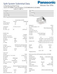
2. Specification<br />
Cooling<br />
Model<br />
Indoor <strong>CS</strong>-<strong>S9NKUW</strong>-1 <strong>CS</strong>-S12NKUW-1<br />
Outdoor CU-S9NKU-1 CU-S12NKU-1<br />
Performance Test Condition ARI ARI<br />
Power Supply<br />
Capacity<br />
Phase, Hz Single, 60 Single, 60<br />
V 208 230 208 230<br />
Min. Mid. Max. Min. Mid. Max. Min. Mid. Max. Min. Mid. Max.<br />
kW 1.20 2.49 3.00 1.20 2.49 3.00 1.20 3.48 3.85 1.20 3.48 3.85<br />
BTU/h 4100 8500 10200 4100 8500 10200 4100 11900 13100 4100 11900 13100<br />
Running Current A - 3.7 - - 3.3 - - 5.1 - - 4.6 -<br />
Input Power W 250 700 900 250 700 900 250 1.00k 1.15k 250 1.00k 1.15k<br />
EER<br />
W/W 4.80 3.56 3.33 4.80 3.56 3.33 4.80 3.48 3.35 4.80 3.48 3.35<br />
Btu/hW 16.40 12.10 11.30 16.40 12.10 11.30 16.40 11.90 11.35 16.40 11.90 11.35<br />
Power Factor % - 91 - - 92 - - 94 - - 95 -<br />
dB-A 40 / 25 / 20 40 / 25 / 20 43 / 28 / 20 43 / 28 / 20<br />
Indoor Noise (H / L / QLo) Power Level dB 56 / - 56 / - 59 / - 59 / -<br />
dB-A 45 / - / - 47 / - / - 46 / - / - 48 / - / -<br />
Outdoor Noise (H / L / QLo)<br />
Power Level dB 60 / - 62 / - 61 / - 63 / -<br />
Max Current (A) / Max Input Power (W) 4.1 / 900 5.4 / 1.22k<br />
Starting Current (A) 3.7 5.1<br />
Min Circuit Ampacity 15.0 15.0<br />
Max. Overcurrent Protection 15.0 15.0<br />
Type Hermetic Motor (Rotary) Hermetic Motor (Rotary)<br />
Compressor Motor Type Brushless (6 poles) Brushless (6 poles)<br />
Output Power W 700 700<br />
Type Cross-flow fan Cross-flow fan<br />
Material ASG20K1 ASG20K1<br />
Motor Type Transistor (8 poles) Transistor (8 poles)<br />
Input Power W 47.0 - 47.0 47.0 - 47.0<br />
Output Power W 30 30<br />
QLo rpm 610 630<br />
Lo rpm 710 790<br />
Speed Me rpm 920 1030<br />
Hi rpm 1130 1270<br />
Indoor Fan<br />
Outdoor Fan<br />
SHi rpm 1230 1400<br />
Type Propeller Propeller<br />
Material PP PP<br />
Motor Type Induction (6 poles) Induction (6 poles)<br />
Input Power W - -<br />
Output Power W 28 28<br />
Speed Hi rpm 760 - 840 760 - 840<br />
Moisture Removal L/h (Pt/h) 0.6 (1.3) 1.1 (2.3)<br />
Indoor Airflow<br />
Outdoor<br />
Airflow<br />
QLo m 3 /min (ft 3 /min) 5.65 (199) 5.30 (187)<br />
Lo m 3 /min (ft 3 /min) 6.76 (239) 6.98 (246)<br />
Me m 3 /min (ft 3 /min) 9.08 (321) 9.49 (335)<br />
Hi m 3 /min (ft 3 /min) 11.4 (400) 12.0 (425)<br />
SHi m 3 /min (ft 3 /min) 12.51 (442) 13.36 (472)<br />
Hi m 3 /min (ft 3 /min) 29.7 (1050) 31.0 (1095) 29.7 (1050) 31.0 (1095)<br />
5
Refrigeration<br />
Cycle<br />
Piping<br />
Dimension<br />
Control Device Capillary Tube Capillary Tube<br />
Refrigerant Oil cm 3 RB68A or Freol Alpha68M (320) RB68A or Freol Alpha68M (320)<br />
Refrigerant Type g (oz) R410A, 965 (34.1) R410A, 980 (34.6)<br />
Height(I/D / O/D) mm (inch) 290 (11-7/16) / 540 (21-9/32) 290 (11-7/16) / 540 (21-9/32)<br />
Width (I/D / O/D) mm (inch) 870 (34-9/32) / 780 (30-23/32) 870 (34-9/32) / 780 (30-23/32)<br />
Depth (I/D / O/D) mm (inch) 204 (8-1/16) / 289 (11-13/32) 204 (8-1/16) / 289 (11-13/32)<br />
Weight Net (I/D / O/D) kg (lb) 9 (20) 37 (82) 9 (20) 37 (82)<br />
Pipe Diameter (Liquid /<br />
Gas)<br />
mm (inch) 6.35 (1/4) / 9.52 (3/8) 6.35 (1/4) / 12.70 (1/2)<br />
Standard length m (ft) 7.5 (24.6) 7.5 (24.6)<br />
Length range (min – max) m (ft) 3 (9.8) ~ 15 (49.2) 3 (9.8) ~ 15 (49.2)<br />
I/D & O/D Height different m (ft) 5 (16.4) 5 (16.4)<br />
Additional Gas Amount g/m (oz/ft) 20 (0.2) 20 (0.2)<br />
Length for Additional Gas m (ft) 7.5 (24.6) 7.5 (24.6)<br />
Drain Hose<br />
Indoor Heat<br />
Exchanger<br />
Outdoor<br />
Heat<br />
Exchanger<br />
Air Filter<br />
Inner Diameter mm (inch) 16.7 (5/8) 16.7 (5/8)<br />
Length mm (inch) 650 (25-5/8) 650 (25-5/8)<br />
Fin Material Aluminium (Pre Coat) Aluminium (Pre Coat)<br />
Fin Type Slit Fin Slit Fin<br />
Row x Stage x FPI 2 x 15 x 19 2 x 15 x 21<br />
Size (W x H x L) inch (1) x (12-3/8) x (24) (1) x (12-3/8) x (24)<br />
Fin Material Aluminium (Blue coated) Aluminium (Blue coated)<br />
Fin Type Corrugate Fin Corrugate Fin<br />
Row x Stage x FPI 2 x 24 x 17 2 x 24 x 17<br />
Size (W x H x L) inch<br />
(1-3/8) x (19-7/8) x (28-1/8)<br />
(26-7/8)<br />
6<br />
(1-3/8) x (19-7/8) x (28-1/8)<br />
(26-7/8)<br />
Material Polypropelene Polypropelene<br />
Type One-touch One-touch<br />
Power Supply Outdoor Outdoor<br />
Power Supply Cord A - -<br />
Thermostat - -<br />
Protection Device - -<br />
Indoor Operation Range<br />
Outdoor Operation Range<br />
DRY BULB WET BULB DRY BULB WET BULB<br />
Maximum 89.6 73.4 89.6 73.4<br />
Minimum 60.8 51.8 60.8 51.8<br />
Maximum 109.4 78.8 109.4 78.8<br />
Minimum 60.8 51.8 60.8 51.8<br />
1. Cooling capacities are based on indoor temperature of 80.6°F DRY BULB, 66°F WET BULB and outdoor air temperature of 95°F DRY BULB,<br />
75.2°F WET BULB.
Cooling<br />
Model<br />
Indoor <strong>CS</strong>-S18NKU-1 <strong>CS</strong>-S22NKU-1<br />
Outdoor CU-S18NKU-1 CU-S22NKU-1<br />
Performance Test Condition ARI ARI<br />
Power Supply<br />
Capacity<br />
Phase, Hz Single, 60 Single, 60<br />
V 208 230 208 230<br />
Min. Mid. Max. Min. Mid. Max. Min. Mid. Max. Min. Mid. Max.<br />
kW 1.30 5.01 5.80 1.30 5.01 5.80 1.30 6.18 6.85 1.30 6.18 6.85<br />
BTU/h 4400 17100 19800 4400 17100 19800 4400 21000 23400 4400 21000 23400<br />
Running Current A - 8.3 - - 7.5 - - 11.2 - - 10.0 -<br />
Input Power W 250 1.65k 1.95k 250 1.65k 1.95k 250 2.25k 2.55k 250 2.25k 2.55k<br />
EER<br />
W/W 5.20 3.04 2.97 5.20 3.04 2.97 5.20 2.75 2.69 5.20 2.75 2.69<br />
Btu/hW 17.60 10.35 10.15 17.60 10.35 10.15 17.60 9.30 9.15 17.60 9.30 9.15<br />
Power Factor % - 96 - - 96 - - 97 - - 98 -<br />
dB-A 47 / 39 / 36 47 / 39 / 36 47 / 39 / 36 47 / 39 / 36<br />
Indoor Noise (H / L / QLo) Power Level dB 63 / - 63 / - 63 / - 63 / -<br />
dB-A 47 / - / - 47 / - / - 50 / - / - 50 / - / -<br />
Outdoor Noise (H / L / QLo)<br />
Power Level dB 61 / - 61 / - 64 / - 64 / -<br />
Max Current (A) / Max Input Power (W) 9.0 / 1.99k 10.8 / 2.48k<br />
Starting Current (A) 8.3 11.2<br />
Min Circuit Ampacity 15.0 20.0<br />
Max. Overcurrent Protection 20.0 25.0<br />
Type Hermetic Motor (Scroll) Hermetic Motor (Scroll)<br />
Compressor Motor Type Brushless (4 poles) Brushless (4 poles)<br />
Output Power W 900 900<br />
Type Cross-flow fan Cross-flow fan<br />
Material ASG30K1 ASG30K1<br />
Motor Type Transistor (8 poles) Transistor (8 poles)<br />
Input Power W 94.8 - 94.8 94.8 - 94.8<br />
Output Power W 30 30<br />
QLo rpm 990 990<br />
Lo rpm 1090 1090<br />
Speed Me rpm 1270 1270<br />
Hi rpm 1460 1460<br />
Indoor Fan<br />
Outdoor Fan<br />
SHi rpm 1500 1500<br />
Type Propeller Propeller<br />
Material PP PP<br />
Motor Type Induction (8 poles) Induction (8 poles)<br />
Input Power W - -<br />
Output Power W 38 38<br />
Speed Hi rpm 500 - 550 550 - 600<br />
Moisture Removal L/h (Pt/h) 1.7 (3.6) 2.9 (6.1)<br />
Indoor Airflow<br />
Outdoor<br />
Airflow<br />
QLo m 3 /min (ft 3 /min) 11.73 (414) 11.73 (414)<br />
Lo m 3 /min (ft 3 /min) 13.15 (464) 13.15 (464)<br />
Me m 3 /min (ft 3 /min) 15.70 (554) 15.70 (554)<br />
Hi m 3 /min (ft 3 /min) 18.4 (650) 18.4 (650)<br />
SHi m 3 /min (ft 3 /min) 18.97 (670) 18.97 (670)<br />
Hi m 3 /min (ft 3 /min) 37.5 (1325) 41.6 (1470) 43.8 (1545) 47.5 (1675)<br />
7
Refrigeration<br />
Cycle<br />
Control Device Expansion Valve Expansion Valve<br />
Refrigerant Oil cm 3 RB68A or Freol Alpha68M (400) RB68A or Freol Alpha68M (400)<br />
Refrigerant Type g (oz) R410A, 1.18k (41.7) R410A, 1.37k (48.4)<br />
Height(I/D / O/D) mm (inch) 290 (11-7/16) / 795 (31-5/16) 290 (11-7/16) / 795 (31-5/16)<br />
Dimension Width (I/D / O/D) mm (inch) 1070 (42-5/32) / 875 (34-15/32) 1070 (42-5/32) / 875 (34-15/32)<br />
Depth (I/D / O/D) mm (inch) 235 (9-9/32) / 320 (12-5/8) 235 (9-9/32) / 320 (12-5/8)<br />
Weight Net (I/D / O/D) kg (lb) 12 (26) 52 (115) 12 (26) 53 (117)<br />
Pipe Diameter (Liquid / Gas) mm (inch) 6.35 (1/4) / 12.70 (1/2) 6.35 (1/4) / 15.88 (5/8)<br />
Piping<br />
Standard length m (ft) 5.0 (16.4) 5.0 (16.4)<br />
Length range (min – max) m (ft) 3 (9.8) ~ 20 (65.6) 3 (9.8) ~ 20 (65.6)<br />
I/D & O/D Height different m (ft) 15 (49.2) 15 (49.2)<br />
Additional Gas Amount g/m (oz/ft) 20 (0.2) 20 (0.2)<br />
Length for Additional Gas m (ft) 10 (32.8) 10 (32.8)<br />
Drain Hose<br />
Indoor Heat<br />
Exchanger<br />
Outdoor<br />
Heat<br />
Exchanger<br />
Air Filter<br />
Inner Diameter mm (inch) 16.7 (5/8) 16.7 (5/8)<br />
Length mm (inch) 650 (25-5/8) 650 (25-5/8)<br />
Fin Material Aluminium (Pre Coat) Aluminium (Pre Coat)<br />
Fin Type Slit Fin Slit Fin<br />
Row x Stage x FPI 2 x 15 x 21 2 x 15 x 21<br />
Size (W x H x L) inch (1) x (12-3/8) x (31-7/8) (1) x (12-3/8) x (31-7/8)<br />
Fin Material Aluminium (Blue coated) Aluminium (Blue coated)<br />
Fin Type Corrugate Fin Corrugate Fin<br />
Row x Stage x FPI 2 x 36 x 19 2 x 36 x 18<br />
Size (W x H x L) inch<br />
(1-3/8) x (29-3/4) x (24-3/8)<br />
(24-3/8)<br />
8<br />
(1-3/8) x (29-3/4) x (33)<br />
(31-7/8)<br />
Material Polypropelene Polypropelene<br />
Type One-touch One-touch<br />
Power Supply Outdoor Outdoor<br />
Power Supply Cord A - -<br />
Thermostat - -<br />
Protection Device - -<br />
Indoor Operation Range<br />
Outdoor Operation Range<br />
DRY BULB WET BULB DRY BULB WET BULB<br />
Maximum 89.6 73.4 89.6 73.4<br />
Minimum 60.8 51.8 60.8 51.8<br />
Maximum 109.4 78.8 109.4 78.8<br />
Minimum 60.8 51.8 60.8 51.8<br />
1. Cooling capacities are based on indoor temperature of 80.6°F DRY BULB, 66°F WET BULB and outdoor air temperature of 95°F DRY BULB,<br />
75.2°F WET BULB.
3. Location of Controls and Components<br />
3.1 Indoor Unit<br />
3.2 Outdoor Unit<br />
3.3 Remote Control<br />
9
4. Dimensions<br />
4.1 Indoor Unit<br />
4.1.1 <strong>CS</strong>-<strong>S9NKUW</strong>-1 <strong>CS</strong>-S12NKUW-1<br />
10
4.1.2 <strong>CS</strong>-S18NKU-1 <strong>CS</strong>-S22NKU-1<br />
11
4.2 Outdoor Unit<br />
4.2.1 CU-S9NKU-1 CU-S12NKU-1<br />
4.2.2 CU-S18NKU-1 CU-S22NKU-1<br />
12
5. Refrigeration Cycle Diagram<br />
5.1 <strong>CS</strong>-<strong>S9NKUW</strong>-1 CU-S9NKU-1 <strong>CS</strong>-S12NKUW-1 CU-S12NKU-1<br />
13
5.2 <strong>CS</strong>-S18NKU-1 CU-S18NKU-1 <strong>CS</strong>-S22NKU-1 CU-S22NKU-1<br />
14
6. Block Diagram<br />
6.1 <strong>CS</strong>-<strong>S9NKUW</strong>-1 CU-S9NKU-1 <strong>CS</strong>-S12NKUW-1 CU-S12NKU-1<br />
15
6.2 <strong>CS</strong>-S18NKU-1 CU-S18NKU-1 <strong>CS</strong>-S22NKU-1 CU-S22NKU-1<br />
16
7. Wiring Connection Diagram<br />
7.1 Indoor Unit<br />
7.1.1 <strong>CS</strong>-<strong>S9NKUW</strong>-1 <strong>CS</strong>-S12NKUW-1<br />
17
7.1.2 <strong>CS</strong>-S18NKU-1 <strong>CS</strong>-S22NKU-1<br />
18
7.2 Outdoor Unit<br />
7.2.1 CU-S9NKU-1 CU-S12NKU-1<br />
19
7.2.2 CU-S18NKU-1<br />
20
7.2.3 CU-S22NKU-1<br />
21
8. Electronic Circuit Diagram<br />
8.1 Indoor Unit<br />
8.1.1 <strong>CS</strong>-<strong>S9NKUW</strong>-1 <strong>CS</strong>-S12NKUW-1<br />
22
8.1.2 <strong>CS</strong>-S18NKU-1 <strong>CS</strong>-S22NKU-1<br />
23
8.2 Outdoor Unit<br />
8.2.1 CU-S9NKU-1 CU-S12NKU-1<br />
24
8.2.2 CU-S18NKU-1<br />
25
8.2.3 CU-S22NKU-1<br />
26
9. Printed Circuit Board<br />
9.1 Indoor Unit<br />
9.1.1 Main Printed Circuit Board<br />
27
9.1.2 Power Printed Circuit Board<br />
9.1.3 Indicator Printed Circuit Board<br />
28
9.2 Outdoor Unit<br />
9.2.1 Main Printed Circuit Board<br />
9.2.1.1 CU-S9NKU-1 CU-S12NKU-1<br />
29
9.2.1.2 CU-S18NKU-1 CU-S22NKU-1<br />
30
10. Installation Instruction<br />
10.1 <strong>S9NKUW</strong>-1 S12NKUW-1<br />
10.1.1 Select the Best Location<br />
10.1.1.1 Indoor Unit<br />
• Do not install the unit in excessive oil fume area<br />
such as kitchen, workshop and etc.<br />
• There should not be any heat source or steam<br />
near the unit.<br />
• There should not be any obstacles blocking the air<br />
circulation.<br />
• A place where air circulation in the room is good.<br />
• A place where drainage can be easily done.<br />
• A place where noise prevention is taken into<br />
consideration.<br />
• Do not install the unit near a door way.<br />
• Ensure the spaces indicated by arrows from the<br />
wall, ceiling, fence or other obstacles.<br />
• Recommended installation height for indoor unit<br />
shall be at least 8.2 ft.<br />
10.1.1.2 Outdoor Unit<br />
• If an awning is built over the unit to prevent direct<br />
sunlight or rain, be careful that heat radiation from<br />
the condenser is not obstructed.<br />
• There should not be any animal or plant which<br />
could be affected by hot air discharged.<br />
• Keep the spaces indicated by arrows from wall,<br />
ceiling, fence or other obstacles.<br />
• Do not place any obstacles which may cause a<br />
short circuit of the discharged air.<br />
• If piping length is over the [piping length for<br />
additional gas], additional refrigerant should be<br />
added as shown in the table.<br />
Example: For <strong>S9NKUW</strong>-1<br />
If the unit is installed at 32.8 ft distance, the quantity of<br />
additional refrigerant should be 1.64 oz .... (32.8 - 24.6)<br />
ft x 0.2 oz/ft = 1.64 oz.<br />
31<br />
10.1.2 Indoor/Outdoor Unit Installation<br />
Diagram
10.1.3 Indoor Unit<br />
10.1.3.1 How to Fix Installation Plate<br />
The mounting wall shall be strong and solid enough to prevent if from the vibration.<br />
The centre of installation plate should be at more than at right and left of the wall.<br />
The distance from installation plate edge to ceiling should more than .<br />
From installation plate left edge to unit’s left side is .<br />
From installation plate right edge to unit’s right side is .<br />
○B : For left side piping, piping connection for liquid should be about from this line.<br />
: For left side piping, piping connection for gas should be about from this line.<br />
1 Mount the installation plate on the wall with 5 screws or more (at least 5 screws).<br />
(If mounting the unit on the concrete wall, consider using anchor bolts.)<br />
o Always mount the installation plate horizontally by aligning the marking-off line with the thread and using<br />
a level gauge.<br />
2 Drill the piping plate hole with ø2 ¾” hole-core drill.<br />
o Line according to the left and right side of the installation plate. The meeting point of the extended line is<br />
the center of the hole. Another method is by putting measuring tape at position as shown in the diagram<br />
above. The hole center is obtained by measuring the distance namely 5 1/16” for left and right hole<br />
respectively.<br />
o Drill the piping hole at either the right or the left and the hole should be slightly slanting to the outdoor<br />
side.<br />
10.1.3.2 To Drill a Hole in the Wall and<br />
Install a Sleeve of Piping<br />
1 Insert the piping sleeve to the hole.<br />
2 Fix the bushing to the sleeve.<br />
3 Cut the sleeve until it extrudes about 19/32”<br />
from the wall.<br />
4 Finish by sealing the sleeve with putty or<br />
caulking compound at the final stage.<br />
32
10.1.3.3 Indoor Unit Installation<br />
10.1.3.4 For the right rear piping<br />
10.1.3.5 For the right bottom piping<br />
10.1.3.6 For the embedded piping<br />
33<br />
(This can be used for left rear piping and bottom<br />
piping also.)
10.1.3.7 Connect the Cable to the Indoor Unit<br />
1. The inside and outside connecting cable can<br />
be connected without removing the front grille.<br />
2. Unscrew the conduit cover and fix the conduit<br />
connector to conduit cover with lock nut, then<br />
secure it against chassis.<br />
3. Connecting wire between indoor unit and<br />
outdoor unit should be UL listed or <strong>CS</strong>A<br />
approved 4 conductor wires minimum AWG16<br />
in accordance with local electric codes.<br />
o Ensure the colour of wires of outdoor unit<br />
and terminal number are the same as the<br />
indoor's respectively.<br />
This equipment must be properly earthed.<br />
o Earth lead wire shall be Yellow/Green<br />
(Y/G) in colour and shall be longer than<br />
other lead wires as shown in the figure for<br />
electrical safety in case of the slipping.<br />
34
10.1.3.8 Wire Stripping and connecting requirement<br />
10.1.3.9 Cutting and flaring the piping<br />
1 Please cut using pipe cutter and then remove the burrs.<br />
2 Remove the burrs by using reamer. If burrs is not removed, gas leakage may be caused. Turn the piping end<br />
down to avoid the metal powder entering the pipe.<br />
3 Please make flare after inserting the flare nut onto the copper pipes.<br />
35
10.1.4 Outdoor Unit<br />
10.1.4.1 Install the Outdoor Unit<br />
• After selecting the best location, start installation to Indoor/Outdoor Unit Installation Diagram.<br />
1 Fix the unit on concrete or rigid frame firmly and horizontally by bolt nut (ø13/32”).<br />
2 When installing at roof, please consider strong wind and earthquake.<br />
Please fasten the installation stand firmly with bolt or nails.<br />
10.1.4.2 Connect the Piping<br />
10.1.4.2.1 Connecting the piping to<br />
indoor<br />
Please make flare after inserting flare nut (locate at<br />
joint portion of tube assembly) onto the copper pipe.<br />
(In case of using long piping)<br />
Connect the piping<br />
• Align the center of piping and sufficiently tighten<br />
the flare nut with fingers.<br />
• Further tighten the flare nut with torque wrench in<br />
specified torque as stated in the table.<br />
10.1.4.2.2 Connecting the piping to<br />
outdoor<br />
Decide piping length and then cut by using pipe cutter.<br />
Remove burrs from cut edge.<br />
Make flare after inserting the flare nut (locate at valve)<br />
onto the copper pipe.<br />
Align center of piping to valve and then tighten with<br />
torque wrench to the specified torque as stated in the<br />
table.<br />
36<br />
Model A B C D<br />
<strong>S9NKUW</strong>-1,<br />
S12NKUW-1<br />
22 7/16” 4 1/8” 23/32” 12 19/32”<br />
Do not over tighten, over tightening may cause gas leakage.<br />
Piping size Torque<br />
1/4” 13.3 lbf.ft<br />
3/8” 31.0 lbf.ft<br />
1/2” 40.6 lbf.ft<br />
5/8” 47.9 lbf.ft<br />
3/4” 73.8 lbf.ft<br />
10.1.4.2.3 Connecting the piping to outdoor multi<br />
Decide piping length and then cut by using pipe cutter. Remove burrs from cut edge.<br />
Make flare after inserting the flare nut (locate at valve) onto the copper pipe.<br />
Align center of piping to valve and then tighten with torque wrench to the specified torque as stated in the table.
10.1.4.2.4 Gas leak checking<br />
Pressure test to system to 400 PSIG with dry nitrogen, in stages. Thoroughly leak check the system.<br />
If the pressure holds, release the nitrogen and proceed to section 10.1.4.3.<br />
10.1.4.3 Evacuation of the equipment<br />
When installing an air conditioner, be sure to evacuate the air inside the indoor unit and pipes in the following<br />
procedures.<br />
1. Connect a charging hose with a push pin to the Low side of a charging set and the service port of the 3-way<br />
valve.<br />
2. Connect the micron gauge between vacuum pump and service port of outdoor units.<br />
3. Turn on the power switch of the vacuum pump and make sure that connect digital micron gauge and to pull<br />
down to a value of 500 microns.<br />
4. To make sure micron gauge a value 500 microns and close the low side valve of the charging set and turn off<br />
the vacuum pump.<br />
5. Disconnect the vacuum pump hose from the service port of the 3-way valve.<br />
6. Tighten the service port caps of the 3-way valve at a torque of 13.3 Ibf.ft with a torque wrench.<br />
7. Remove the valve caps of both of the 2-way valve and 3-way valve. Position both of the valves to “Open”<br />
using a hexagonal wrench (5/32”).<br />
8. Mount valve caps onto the 2-way valve and the 3-way valve.<br />
o Be sure to check for gas leakage.<br />
10.1.4.4 Connect the Cable to the Outdoor Unit<br />
1. Remove Top panel.<br />
2. Remove Control Board Cover (Resin and Metal).<br />
3. Remove Plugs.<br />
4. Fix the conduit connectors to the knockout holes with<br />
lock-nuts, then secure them against the side panel.<br />
5. All wires pass through conduits.<br />
6. Connecting wire between indoor unit and outdoor unit<br />
should be UL listed or <strong>CS</strong>A approved 4 conductor<br />
wires minimum AWG16 in accordance with local<br />
electric codes.<br />
7. Wire connection to the power supply (208/230V 60Hz)<br />
through circuit breaker.<br />
o Connect the UL listed or <strong>CS</strong>A approved wires<br />
minimum AWG14 to the terminal board, and<br />
connect the other end of the wires to ELCB /<br />
GFCI.<br />
8. Connect the power supply cord and connecting wire<br />
between indoor unit and outdoor unit according to the diagram below.<br />
37
9. Secure the wire onto the control board with the holder<br />
(clamper).<br />
10. After completing wiring connections, reattach the control<br />
board cover (Metal and Resin) and the top panel to the<br />
original position with the screws.<br />
11. For wire stripping and connection requirement, refer to<br />
instruction of indoor unit.<br />
This equipment must be properly earthed.<br />
o Earth lead wire shall be Yellow/Green (Y/G) in colour<br />
and shall be longer than other lead wires as shown in<br />
the figure for electrical safety in case of the slipping.<br />
10.1.4.5 Piping Insulation<br />
1. Please carry out insulation at pipe connection portion as mentioned in Indoor/Outdoor Unit Installation<br />
Diagram. Please wrap the insulated piping end to prevent water from going inside the piping.<br />
2. If drain hose or connecting piping is in the room (where dew may form), please increase the insulation by<br />
using POLY-E FOAM with thickness ¼” or above.<br />
38
10.2 S18NKU-1 S22NKU-1<br />
10.2.1 Select the Best Location<br />
10.2.1.1 Indoor Unit<br />
• Do not install the unit in excessive oil fume areas<br />
such as kitchens, workshops etc.<br />
• There should not be any heat source or steam<br />
near the unit.<br />
• There should not be any obstacles blocking the air<br />
circulation.<br />
• A place where air circulation in the room is good.<br />
• A place where drainage can be easily done.<br />
• A place where noise prevention is taken into<br />
consideration.<br />
• Do not install the unit near a doorway.<br />
• Ensure the spaces indicated by arrows from the<br />
wall, ceiling, fence or other obstacles.<br />
• Recommended installation height for indoor unit<br />
shall be at least 8.2 ft.<br />
10.2.1.2 Outdoor Unit<br />
• If an awning is built over the unit to prevent direct<br />
sunlight or rain, be careful that heat radiation from<br />
the condenser is not obstructed.<br />
• There should not be any animal or plant which<br />
could be affected by hot air discharged.<br />
• Keep the spaces indicated by arrows from wall,<br />
ceiling, fence or other obstacles.<br />
• Do not place any obstacles which may cause a<br />
short circuit of the discharged air.<br />
• If piping length is over the [piping length for<br />
additional gas], additional refrigerant should be<br />
added as shown in the table.<br />
• Recommended installation height for outdoor unit<br />
should be above the seasonal snow level.<br />
Example: For S18NKU-1<br />
If the unit is installed at 41 ft distance, the quantity of<br />
additional refrigerant should be 1.64 oz .... (41 - 32.8)<br />
ft x 0.2 oz/ft = 1.64 oz.<br />
39<br />
10.2.2 Indoor/Outdoor Unit Installation<br />
Diagram
10.2.3 Indoor Unit<br />
10.2.3.1 How to Fix Installation Plate<br />
The mounting wall must be strong and solid enough to prevent if from the vibration.<br />
The centre of installation plate should be at more than at right and left of the wall.<br />
The distance from installation plate edge to ceiling should more than .<br />
From installation plate left edge to unit’s left side is .<br />
From installation plate right edge to unit’s right side is .<br />
○B : For left side piping, piping connection for liquid should be about from this line.<br />
: For left side piping, piping connection for gas should be about from this line.<br />
1 Mount the installation plate on the wall with 5 screws or more (at least 5 screws).<br />
(If mounting the unit on the concrete wall, consider using anchor bolts.)<br />
o Always mount the installation plate horizontally by aligning the marking-off line with the thread and using<br />
a level gauge.<br />
2 Drill the piping plate hole with ø2 ¾” hole-core drill.<br />
o Line according to the left and right side of the installation plate. The meeting point of the extended line is<br />
the center of the hole. Another method is by putting measuring tape at position as shown in the diagram<br />
above. The hole center is obtained by measuring the distance namely 5 1/16” for left and right hole<br />
respectively.<br />
o Drill the piping hole at either the right or the left and the hole should be slightly slanting to the outdoor<br />
side.<br />
10.2.3.2 To Drill a Hole in the Wall and<br />
Install a Sleeve of Piping<br />
1 Insert the piping sleeve to the hole.<br />
2 Fix the bushing to the sleeve.<br />
3 Cut the sleeve until it extrudes about 19/32”<br />
from the wall.<br />
4 Finish by sealing the sleeve with putty or<br />
caulking compound at the final stage.<br />
40
10.2.3.3 Indoor Unit Installation<br />
10.2.3.4 For the right rear piping<br />
10.2.3.5 For the right bottom piping<br />
10.2.3.6 For the embedded piping<br />
41<br />
(This can be used for left rear piping and bottom<br />
piping also.)
10.2.3.7 Connect the Cable to the Indoor Unit<br />
1. The inside and outside connecting cable can<br />
be connected without removing the front grille.<br />
2. Unscrew the conduit cover and fix the conduit<br />
connector to conduit cover with lock nut, then<br />
secure it against chassis.<br />
3. Connecting wire between indoor unit and<br />
outdoor unit should be UL listed or <strong>CS</strong>A<br />
approved 4 conductor wires minimum AWG16<br />
in accordance with local electric codes.<br />
o Ensure the colour of wires of outdoor unit<br />
and terminal number are the same as the<br />
indoor's respectively.<br />
This equipment must be properly earthed.<br />
o Earth lead wire shall be Yellow/Green<br />
(Y/G) in colour and shall be longer than<br />
other lead wires as shown in the figure for<br />
electrical safety in case of the slipping.<br />
42
10.2.3.8 Wire Stripping and connecting requirement<br />
10.2.3.9 Cutting and flaring the piping<br />
1 Please cut using pipe cutter and then remove the burrs.<br />
2 Remove the burrs by using reamer. If burrs is not removed, gas leakage may be caused. Turn the piping end<br />
down to avoid the metal powder entering the pipe.<br />
3 Please make flare after inserting the flare nut onto the copper pipes.<br />
43
10.2.4 Outdoor Unit<br />
10.2.4.1 Install the Outdoor Unit<br />
• After selecting the best location, start installation to Indoor/Outdoor Unit Installation Diagram.<br />
1 Fix the unit on concrete or rigid frame firmly and horizontally by bolt nut (ø13/32”).<br />
2 When installing at roof, please consider strong wind and earthquake.<br />
Please fasten the installation stand firmly with bolt or nails.<br />
10.2.4.2 Connect the Piping<br />
10.2.4.2.1 Connecting the piping to<br />
indoor<br />
Please make flare after inserting flare nut (locate at<br />
joint portion of tube assembly) onto the copper pipe.<br />
(In case of using long piping)<br />
Connect the piping<br />
• Align the center of piping and sufficiently tighten<br />
the flare nut with fingers.<br />
• Further tighten the flare nut with torque wrench in<br />
specified torque as stated in the table.<br />
10.2.4.2.2 Connecting the piping to<br />
outdoor<br />
Decide piping length and then cut by using pipe cutter.<br />
Remove burrs from cut edge.<br />
Make flare after inserting the flare nut (locate at valve)<br />
onto the copper pipe.<br />
Align center of piping to valve and then tighten with<br />
torque wrench to the specified torque as stated in the<br />
table.<br />
44<br />
Model A B C D<br />
S18NKU-1,<br />
S22NKU-1<br />
24 1/8” 5 5/32” 5/8” 14 3/32”<br />
Do not over tighten, over tightening may cause gas leakage.<br />
Piping size Torque<br />
1/4” 13.3 lbf.ft<br />
3/8” 31.0 lbf.ft<br />
1/2” 40.6 lbf.ft<br />
5/8” 47.9 lbf.ft<br />
3/4” 73.8 lbf.ft<br />
10.2.4.2.3 Gas leak checking<br />
Pressure test to system to 400 PSIG with dry nitrogen, in stages. Thoroughly leak check the system.<br />
If the pressure holds, release the nitrogen and proceed to section 10.2.4.3.
10.2.4.3 Evacuation of the equipment<br />
When installing an air conditioner, be sure to evacuate the air inside the indoor unit and pipes in the following<br />
procedures.<br />
1. Connect a charging hose with a push pin to the Low side of a charging set and the service port of the 3-way<br />
valve.<br />
2. Connect the micron gauge between vacuum pump and service port of outdoor units.<br />
3. Turn on the power switch of the vacuum pump and make sure that connect digital micron gauge and to pull<br />
down to a value of 500 microns.<br />
4. To make sure micron gauge a value 500 microns and close the low side valve of the charging set and turn off<br />
the vacuum pump.<br />
5. Disconnect the vacuum pump hose from the service port of the 3-way valve.<br />
6. Tighten the service port caps of the 3-way valve at a torque of 13.3 Ibf.ft with a torque wrench.<br />
7. Remove the valve caps of both of the 2-way valve and 3-way valve. Position both of the valves to “Open”<br />
using a hexagonal wrench (5/32”).<br />
8. Mount valve caps onto the 2-way valve and the 3-way valve.<br />
o Be sure to check for gas leakage.<br />
10.2.4.4 Connect the Cable to the Outdoor Unit<br />
1. Remove control board cover (Resin and Metal).<br />
2. Remove particular plate.<br />
3. Remove plugs.<br />
4. Fix the conduit connectors to the knockout holes with lock-nuts, then secure them against the side panel.<br />
5. All wires pass through conduits & particular plate’s opening hole.<br />
6. Connecting wire between indoor unit and outdoor unit should be UL listed or <strong>CS</strong>A approved 4 conductor<br />
wires minimum AWG16 in accordance with local electric codes.<br />
7. Wire connection to the power supply (208/230V 60Hz) through circuit breaker.<br />
o Connect the UL listed or <strong>CS</strong>A approved wires minimum AWG12 to the terminal board, and connect the<br />
other end of the wires to ELCB / GFCI.<br />
8. Connect the power supply cord and connecting wire between indoor unit and outdoor unit according to the<br />
diagram below.<br />
45
9. Secure the wire onto the control board with the holder (clamper).<br />
10. After completing wiring connections, reattach the particular plate and control board cover (metal and resin) to<br />
the original position with the screws.<br />
11. For wire stripping and connection requirement, refer to instruction of indoor unit.<br />
This equipment must be properly earthed.<br />
o Earth lead wire shall be Yellow/Green (Y/G) in colour and longer than other lead wires for electrical<br />
safety in case of the slipping.<br />
10.2.4.5 Piping Insulation<br />
1. Please carry out insulation at pipe connection portion as mentioned in Indoor/Outdoor Unit Installation<br />
Diagram. Please wrap the insulated piping end to prevent water from going inside the piping.<br />
2. If drain hose or connecting piping is in the room (where dew may form), please increase the insulation by<br />
using POLY-E FOAM with thickness ¼” or above.<br />
46
11. Operation Control<br />
11.1 Basic Function<br />
Inverter control, which equipped with a microcomputer in determining the most suitable operation mode as time<br />
passes, automatically adjusts output power for maximum comfort always. In order to achieve the suitable operation<br />
mode, the microcomputer maintains the set temperature by measuring the temperature of the environment and<br />
performing temperature shifting. The compressor at outdoor unit is operating following the frequency instructed by<br />
the microcomputer at indoor unit that judging the condition according to internal setting temperature and intake air<br />
temperature.<br />
11.1.1 Internal Setting Temperature<br />
Once the operation starts, remote control setting temperature will be taken as base value for temperature shifting<br />
processes. These shifting processes are depending on the air conditioner settings and the operation environment.<br />
The final shifted value will be used as internal setting temperature and it is updated continuously whenever the<br />
electrical power is supplied to the unit.<br />
11.1.2 Cooling Operation<br />
11.1.2.1 Thermostat control<br />
• Compressor is OFF when intake Air Temperature - Internal Setting Temperature < 29.3°F.<br />
• Compressor is ON after waiting for 3 minutes, if the Intake Temperature - Internal Setting Temperature ><br />
Compressor OFF point.<br />
11.1.3 Soft Dry Operation<br />
Remote Control Setting Temperature<br />
60.8°F ~ 86°F<br />
Indoor Air Temperature Shifting<br />
Outdoor Air Temperature Shifting<br />
Powerful Mode Shifting<br />
Setting Temperature Limit Checking<br />
(Min: 60.8°F; Max: 91.4°F)<br />
Internal Setting Temperature<br />
11.1.3.1 Thermostat control<br />
• Compressor is OFF when Intake Temperature - Internal Setting Temperature < 28.4°F.<br />
• Compressor is ON after waiting for 3 minutes, if the Intake Air Temperature - Internal Setting Temperature ><br />
Compressor OFF point.<br />
11.1.3.2 Automatic Operation<br />
• This mode can be set using remote control and the operation is decided by indoor intake air temperature.<br />
• During operation mode judgment at the beginning of the Auto Mode operation, indoor fan motor (with speed of<br />
Lo-) is running for 30 seconds to detect the indoor intake air temperature.<br />
• The operation mode is decided based on below chart.<br />
73.4°F<br />
• After the operation mode is decided, the unit operation will follow the respective operation mode control.<br />
47<br />
Cooling<br />
operation<br />
Soft Dry<br />
operation<br />
Indoor intake<br />
Air Temp
11.2 Indoor Fan Motor Operation<br />
11.2.1 Basic Rotation Speed<br />
• Manual Fan Speed<br />
o Fan motor’s number of rotation is determined according to remote control setting.<br />
Remote control ○ ○ ○ ○ ○<br />
Tab Hi Me+ Me Me- Lo<br />
• Auto Fan Speed<br />
o According to room temperature and setting temperature, indoor fan speed is determined automatically.<br />
o The indoor fan will operate according to pattern below.<br />
Fan Speed a b c d e f g h a b<br />
Higher<br />
Medium<br />
Lower<br />
48<br />
[1 pattern : 10s]<br />
• Feedback control<br />
o Immediately after the fan motor is started, feedback control is performed once every second.<br />
o During fan motor on, if fan motor feedback ≥ 2550 rpm or
11.5.1 Vertical Airflow<br />
Operation Mode Airflow Direction<br />
1<br />
Vane Angle (°)<br />
2 3 4 5<br />
Cooling<br />
Auto<br />
Manual 20 26<br />
20 ~ 45<br />
32 37 45<br />
Soft Dry<br />
Auto<br />
Manual 20 26<br />
20 ~ 45<br />
32 37 45<br />
• Automatic vertical airflow direction can be set using remote control; the vane swings up and down within the<br />
angles as stated above. It does not swing during fan motor stop. When the air conditioner is stopped using<br />
remote control, the vane will shift to close position.<br />
• Manual vertical airflow direction can be set using remote control; the angles of the vane are as stated above and<br />
the positions of the vane are as figure below. When the air conditioner is stopped using remote control, the vane<br />
will shift to close position.<br />
11.5.2 Horizontal Airflow<br />
11.5.2.1 S9NK, S12NK<br />
The horizontal airflow direction louvers can be adjusted manually by hand.<br />
11.5.2.2 S18NK, S22NK<br />
• Automatic airflow direction can be set using remote control; the vane swings left and right within the angles as<br />
stated below. It does not swing during fan motor stop.<br />
Operation Mode Vane Angle (°)<br />
Cooling and soft dry 68 ~112<br />
• Manual vertical airflow direction can be set using remote control; the angles of the vane are as stated below and<br />
the positions of the vane are as figure below:<br />
11.6 Quiet Operation (Cooling Mode/Cooling Area of Dry Mode)<br />
• Purpose<br />
o To provide quiet cooling operation compare to normal operation.<br />
1<br />
2<br />
• Control condition<br />
o Quiet operation start condition<br />
When Quiet button at remote control is pressed Quiet INDICATOR illuminates.<br />
o Quiet operation stop condition<br />
When one of the following conditions is satisfied, quiet operation stops:<br />
• Powerful button is pressed.<br />
• Stop by OFF/ON button.<br />
• OFF Timer activates.<br />
• Quiet button is pressed again.<br />
3<br />
4<br />
5<br />
49<br />
Side View<br />
140°<br />
Close position
When quiet operation is stopped, operation is shifted to normal operation with previous setting.<br />
When fan speed is changed, quiet operation is shifted to quiet operation of the new fan speed.<br />
When operation mode is changed, quiet operation is shifted to quiet operation of the new mode.<br />
During quiet operation, if ON timer activates, quiet operation maintains.<br />
After off, when on back, quiet operation is not memorized.<br />
• Control content<br />
o Fan speed is changed from normal setting to quiet setting of respective fan speed. This is to reduce sound of<br />
Hi, Me, Lo for 3dB (more than 3dB for some models).<br />
o Fan speed for quiet operation is -1 step from setting fan speed.<br />
11.7 Powerful Mode Operation<br />
• When the powerful mode is selected, the internal setting temperature will shift lower up to 35.6°F (for<br />
Cooling/Soft Dry) than remote control setting temperature for 20 minutes and the fan speed will increase to<br />
achieve the setting temperature quickly.<br />
• Powerful operation stops condition<br />
o When one of the following condition is satisfied, powerful operation stops:<br />
Quiet button is pressed.<br />
Stop by OFF/ON button.<br />
OFF Timer activates.<br />
Powerful button is pressed again.<br />
Powerful operation continue for 20 minutes.<br />
11.8 Timer Control<br />
11.8.1 ON Timer Control<br />
ON timer can be set using remote control, the unit with timer set will start operate earlier than the setting time. This is<br />
to provide a comfortable environment when reaching the set ON time.<br />
60 minutes before the set time, indoor (at fan speed of Lo-) and outdoor fan motor start operate for 30 seconds to<br />
determine the indoor intake air temperature and outdoor air temperature in order to judge the operation starting time.<br />
From the judgment, the decided operation will start operation earlier than the set time as shown below.<br />
Indoor intake air<br />
temperature (°F)<br />
11.8.2 OFF Timer Control<br />
OFF timer can be set using remote control, the unit with timer set will stop operate at set time.<br />
11.9 Random Auto Restart Control<br />
86<br />
77<br />
5 min<br />
10 min<br />
86 95<br />
• When the power supply is cut off during the operation of air conditioner, the compressor will re-operate within<br />
three to four minutes. There are 10 patterns to be selected randomly after power supply resumes.<br />
• This control is not applicable during OFF/ON Timer setting.<br />
50<br />
15 min<br />
Cooling / Soft Dry<br />
Outdoor air<br />
temperature (°F)
11.10 Indication Panel<br />
LED POWER TIMER QUIET POWERFUL<br />
Color Green Orange Orange Orange<br />
Light ON Operation ON Timer Setting ON Quiet Mode ON Powerful Mode ON<br />
Light OFF Operation OFF Timer Setting OFF Quiet Mode OFF Powerful Mode OFF<br />
Note:<br />
• If POWER LED blinks, the possible operation of the unit is operation mode judgment, or ON timer sampling.<br />
• If TIMER LED blinks, there is an abnormal operation occurs.<br />
51
12. Protection Control<br />
12.1 Restart Control (Time Delay Safety Control)<br />
• The compressor will not turn on within 3 minutes from the moment operation stops, although the unit is turned on<br />
again by pressing OFF/ON button at remote control within this period.<br />
• This control is not applicable if the power supply is cut off and on again.<br />
• This phenomenon is to balance the pressure inside the refrigerant cycle.<br />
12.2 30 Seconds Forced Operation<br />
• Once the air conditioner is turned on, the compressor will not stop within 30 seconds in a normal operation<br />
although the intake air temperature has reached the thermo-off temperature. However, force stop by pressing the<br />
OFF/ON button at the remote control is permitted or the Auto OFF/ON button at indoor unit.<br />
• The reason for the compressor to force operation for minimum 30 seconds is to allow the refrigerant oil run in a<br />
full cycle and return back to the outdoor unit.<br />
12.3 Total Running Current Control<br />
• When the outdoor unit total running current (AC) exceeds X value, the frequency instructed for compressor<br />
operation will be decreased.<br />
• If the running current does not exceed X value for 5 seconds, the frequency instructed will be increased.<br />
Model S9*** S12*** S18*** S22***<br />
Operation Mode X (A) X (A) X (A) X (A)<br />
Cooling / Soft Dry (A) 3.89 5.19 8.77 11.05<br />
Cooling / Soft Dry (B) 3.28 4.63 7.72 9.55<br />
• The first 30 minutes of cooling operation, (A) will be applied.<br />
12.4 IPM (Power Transistor) Prevention Control<br />
12.4.1 S9NK, S12NK<br />
• Overheating Prevention Control<br />
o When the IPM temperature rises to 212°F, compressor operation will stop immediately.<br />
o Compressor operation restarts after 3 minutes the temperature decreases to 203°F.<br />
• DC Peak Current Control<br />
o When electric current to IPM exceeds set value of 18.5A, the compressor will stop operate. Then, operation<br />
will restart after 3 minutes.<br />
o If the set value exceeds again more than 30 seconds after the compressor starts, the operation will restart<br />
after 2 minutes.<br />
o If the set value exceeds again within 30 seconds after the compressor starts, the operation will restart after 1<br />
minute. If this condition repeats continuously for 7 times, all indoor and outdoor relays will be cut off.<br />
o Timer LED will be blinking (F99 is indicated).<br />
52
12.4.2 S18NK, S22NK<br />
• Overheating Prevention Control<br />
o When the IPM temperature rises to 212°F, compressor operation will stop immediately.<br />
o Compressor operation restarts after 3 minutes the temperature decreases to 203°F.<br />
• DC Peak Current Control<br />
o When electric current to IPM exceeds set value of 29.9A, the compressor will stop operate. Then, operation<br />
will restart after 3 minutes.<br />
o If the set value is exceeded again more than 30 seconds after the compressor starts, the operation will<br />
restart after 2 minute.<br />
o If the set value is exceeded again within 30 seconds after the compressor starts, the operation will restart<br />
after 1 minute. If this condition repeats continuously for 7 times, all indoor and outdoor relays will be cut off.<br />
12.5 Compressor Overheating Prevention Control (For S18, S22NK only)<br />
• Instructed frequency for compressor operation will be regulated by compressor discharge temperature. The<br />
changes of frequency are as below.<br />
• If compressor discharge temperature exceeds 233.6°F, compressor will be stopped, occurs 4 times per 20<br />
minutes, timer LED will be blinking. “F97” is indicated.<br />
12.6 Low Pressure Protection Control (Gas Leakage Detection)<br />
• Control start conditions<br />
o For 5 minutes, the compressor continously operates and outdoor total current is between 0.66A and 1.25A<br />
(S9NK and S12NK) or 0.81A and 1.23A (S18NK and S22NK).<br />
o During Cooling and Soft Dry operation:<br />
Indoor suction temperature – indoor piping temperature is below 39.2°F<br />
• Control contents<br />
o Compressor stops (and restart after 3 minutes).<br />
o If the conditions above happened 2 times within 20 minutes, the unit will:<br />
Stop operation<br />
Timer LED blinks and “F91” indicated.<br />
12.7 Low Frequency Protection Control 1<br />
• When the compressor operates at frequency lower than 26Hz continued for 20 minutes, the operation frequency<br />
will be changed to 25Hz for 2 minutes. (For S9NK and S12NK)<br />
• When the compressor operates at frequency lower than 25Hz continued for 240 minutes, the operation frequency<br />
will be change to 24Hz for 2 minutes. (For S18NK and S22NK)<br />
12.8 Low Frequency Protection Control 2<br />
• When all below conditions comply, minimum limit of compressor frequency will be set.<br />
Temperature, T, for:<br />
53<br />
Cooling / Soft Dry<br />
S9NK and S12NK S18NK and S22NK<br />
Indoor intake air (°F) T < 59 or T ≥ 86 T < 57.2 or ≥ 86<br />
Outdoor air (°F) T < 60.8 or T ≥ 100.4 T < 55.4 or T ≥ 100.4<br />
Indoor heat exchanger (°F) T < 86 T < 86
12.9 Outdoor Air Temperature Control<br />
• The compressor operating frequency is regulated in accordance to the outdoor air temperature as shown in the<br />
diagram below.<br />
• This control will begin 1 minute after the compressor starts.<br />
• Compressor frequency will adjust based on outdoor air temperature.<br />
100.4°F or 77°F (For S18/22NK)<br />
Outdoor air temperature<br />
12.10 Cooling Overload Control<br />
• Pipe temperature limitation / restriction.<br />
o Detects the outdoor pipe temperature and carry out restriction / limitation below (Limit the compressor<br />
operation frequency)<br />
o The compressor stops if outdoor pipe temperature exceeds 141.8°F (for S9NK and S12NK), 145.4°F (for<br />
S18NK and S22NK).<br />
o If the compressor stops 4 times in 20 minutes, Timer LED blinks (“F95” indicated: Outdoor high pressure rise<br />
protection)<br />
12.11 Freeze Prevention Control<br />
• When indoor heat exchanger temperature is lower than 32°F continuously for 6 minutes, compressor will stops<br />
operation.<br />
• Compressor will resume its operation 3 minutes after the indoor heat exchanger is higher than 55.4°F.<br />
• At the same time, indoor fan speed will be higher than during its normal operation.<br />
• If the indoor heat exchanger temperature is higher than 55.4°F for 5 minutes, the fan speed will return to its<br />
normal operation.<br />
12.12 Freeze Prevention Control 2<br />
• Control start conditions<br />
o During Cooling operation and soft dry operation<br />
During thermo OFF condition, indoor intake temperature is less than 50°F or<br />
Compressor stops for freeze prevention control<br />
o Either one of the conditions above occurs 5 times in 60 minutes.<br />
• Control contents<br />
o Operation stops<br />
o Timer LED blinks and “H99” indicated<br />
12.13 Dew Prevention Control<br />
• To prevent dew formation at indoor unit discharge area.<br />
• This control will be activated if:<br />
o Cooling mode or Quiet mode is activated.<br />
o Remote control setting temperature is less than 77°F.<br />
o Fan Speed is at CLo or QLo.<br />
o Room temperature is constant (±33.8°F) for 30 minutes.<br />
o Compressor is continuously running.<br />
• Fan speed will be adjusted accordingly in this control.<br />
o Fan speed will be increased slowly if the unit is in quiet mode but no change in normal cooling mode.<br />
Free<br />
Limited Frequency<br />
54<br />
98.6°F or 71.6°F (For S18/22NK)
13. Servicing Mode<br />
13.1 Auto Off/On Button<br />
Auto OFF/ON<br />
Button Pressed<br />
55<br />
Auto OFF/ON<br />
Button Pressed<br />
5 sec<br />
Auto Operation Test Run Operation<br />
(Forced Cooling Operation)<br />
1 AUTO OPERATION MODE<br />
The Auto Operation will be activated immediately once the Auto OFF/ON button is pressed. This operation<br />
can be used to operate air conditioner with limited function if remote control is misplaced or malfunction.<br />
2 TEST RUN OPERATION (FOR PUMP DOWN/SERVICING PURPOSE)<br />
The Test Run Operation will be activated if the Auto OFF/ON button is pressed continuously for more than 5<br />
seconds. A “beep” sound will be heard at the fifth seconds, in order to identify the starting of this operation.<br />
The Auto OFF/ON button may be used together with remote control to set / change the advance setting of air<br />
conditioner operation.<br />
3 REMOTE CONTROL NUMBER SWITCH MODE<br />
The Remote Control Number Switch Mode will be activated if the Auto OFF/ON button is pressed<br />
continuously for more than 11 seconds (3 “beep” sounds will occur at 11 th seconds to identify the Remote<br />
Control Number Switch Mode is in standby condition), press “AC Reset” button and then press any button at<br />
remote control to transmit and store the desired transmission code to the EEPROM.<br />
There are 4 types of remote control transmission code could be selected. The indoor unit will only operate<br />
when received signal with same transmission code from remote control. This could prevent signal<br />
interference when there are 2 or more units installed nearby together.<br />
To change remote control transmission code, short or open jumpers at the remote control printed circuit<br />
board.<br />
Remote Control Printed Circuit Board<br />
Jumper A (J-A) Jumper B (J-B) Remote Control No.<br />
Short Open A (Default)<br />
Open Open B<br />
Short Short C<br />
Open Short D<br />
4 REMOTE CONTROL RECEIVING SOUND OFF/ON MODE<br />
The Remote Control Receiving Sound OFF/ON Mode will be activated if the Auto OFF/ON button is pressed<br />
continuously for more than 16 seconds (4 “beep” sounds will occur at 16 th seconds to identify the Remote<br />
Control Receiving Sound OFF/ON Mode is in standby condition) and press “AC Reset” button and then press<br />
“Check” button at remote control.<br />
Press Auto OFF/ON button to toggle remote control receiving sound.<br />
- Short “beep”: Turn ON remote control receiving sound.<br />
- Long “beep”: Turn OFF remote control receiving sound.<br />
After Auto OFF/ON button is pressed, the 20 seconds counter for Remote Control Receiving Sound OFF/ON<br />
Mode is restarted.<br />
Stop
13.2 Remote Control Button<br />
13.2.1 SET Button<br />
• To check remote control transmission code and store the transmission code to EEPROM<br />
o Press “Set” button continuously for 10 seconds by using pointer<br />
o Press “Timer Set” button unit a “beep” sound is heard as confirmation of transmission code change.<br />
13.2.2 RESET (RC)<br />
• To clear and restore the remote control setting to factory default.<br />
o Press once to clear the memory<br />
13.2.3 RESET (AC)<br />
• To restore the unit’s setting to factory default.<br />
o Press once to restore the unit’s setting<br />
13.2.4 TIMER ▲<br />
• To change indoor unit indicators’ intensity:<br />
o Press continuously for 5 seconds.<br />
13.2.5 TIMER ▼<br />
• To change remote control display from Degree Celsius (°C) to Degree Fahrenheit (°F)<br />
o Press continuously for 10 seconds.<br />
56
14. Troubleshooting Guide<br />
14.1 Refrigeration Cycle System<br />
In order to diagnose malfunctions, ensure the air conditioner is free<br />
from electrical problems before inspecting the refrigeration cycle.<br />
Such problems include insufficient insulation, problem with the<br />
power source, malfunction of a compressor and a fan. The normal<br />
outlet air temperature and pressure of the refrigeration cycle<br />
depends on various conditions, the standard values for them are<br />
shown in the table to the right.<br />
Different in the intake<br />
and outlet<br />
air temperatures<br />
Value of electric current<br />
during operation<br />
Gas side<br />
pressure<br />
More than 46.4°F<br />
(15 minutes after an<br />
operation is started) at<br />
cooling mode.<br />
Less than 46.4°F at the cooling mode<br />
Lower than specified<br />
Higher than specified<br />
Cooling<br />
Mode High<br />
Low<br />
Low<br />
57<br />
Normal<br />
Normal Pressure and Outlet Air Temperature (Standard)<br />
Cooling Mode<br />
Dusty condenser<br />
preventing heat radiation<br />
Excessive amount<br />
of refrigerant<br />
Inefficient compressor<br />
Insufficient refrigerant<br />
Clogged strainer or<br />
capillary cube<br />
Gas Pressure<br />
PSI<br />
(kg/cm 2 G)<br />
130.5 ~ 174.0<br />
(9 ~ 12)<br />
Outlet air<br />
Temperature<br />
(°F)<br />
53.6 ~ 60.8<br />
Condition: Indoor fan speed = High<br />
Outdoor temperature = 95°F at cooling mode.<br />
Compressor operate at rated frequency<br />
• Measuring the air<br />
temperature different<br />
• Measuring electric current<br />
during operation<br />
• Measuring gas side<br />
pressure
14.1.1 Relationship between the condition of the air conditioner and pressure and<br />
electric current<br />
Condition of the<br />
Cooling Mode<br />
air conditioner Low Pressure High Pressure Electric current during operation<br />
Insufficient refrigerant<br />
(gas leakage)<br />
Clogged capillary tube or<br />
strainer<br />
<br />
<br />
Short circuit in the indoor unit <br />
Heat radiation deficiency<br />
of the outdoor unit<br />
<br />
Inefficient compression <br />
• Carry out the measurement of pressure, electric current, and temperature fifteen minutes after an operation is started.<br />
58
14.2 Breakdown Self Diagnosis Function<br />
14.2.1 Self Diagnosis Function (Three Digits Alphanumeric Code)<br />
• Once error occurred during operation, the unit will stop its operation, and Timer LED blinks.<br />
• Although Timer LED goes off when power supply is turned off, if the unit is operated under a breakdown<br />
condition, the LED will ON again.<br />
• In operation after breakdown repair, the Timer LED will not blink. The last error code (abnormality) will be stored<br />
in IC memory.<br />
14.2.2 To Make a Diagnosis<br />
1 Timer LED starts to blink and the unit automatically stops the<br />
operation.<br />
2 Press the CHECK button on the remote control continuously for 5<br />
seconds.<br />
3 “- -“ will be displayed on the remote control display.<br />
Note: Display only for “- -“ (No signal transmission, no receiving<br />
sound and no Power LED blinking)<br />
4 Press the TIMER ▲ or ▼ button on the remote control. The code<br />
“H00” (no abnormality) will be displayed and signal will be transmit to<br />
the main unit.<br />
5 Each press of the button (▲ or ▼) will increase error code number<br />
and transmit error code signal to the main unit.<br />
6 When the latest abnormality code on the main unit and code<br />
transmitted from the remote control are matched, Power LED will<br />
light up for 30 seconds and a “beep” sound (continuously for 4<br />
seconds) will be heard. If no codes are matched, Power LED will light up for 0.5 seconds and no sound will<br />
be heard.<br />
7 The breakdown diagnosis mode will be canceled unless pressing the CHECK button continuously for 5<br />
seconds or operating the unit for 30 seconds.<br />
8 The LED will be off if the unit is turned off or the RESET button on the main unit is pressed.<br />
14.2.3 To Display Memorized Error Code (Protective Operation)<br />
1 Turn power on.<br />
2 Press the CHECK button on the remote control<br />
3 “- -“ will be displayed on the remote control display.<br />
Note: Display only for “- -“ (No signal transmission, no receiving sound and no Power LED blinking)<br />
4 Press the TIMER ▲ or ▼ button on the remote control. The code “H00” (no abnormality) will be displayed<br />
and signal will be transmit to the main unit.<br />
5 Each press of the button (▲ or ▼) will increase error code number and transmit error code signal to the main<br />
unit.<br />
6 When the latest abnormality code on the main unit and code transmitted from the remote control are matched,<br />
Power LED will light up for 30 seconds and a “beep” sound (continuously for 4 seconds) will be heard. If no<br />
codes are matched, Power LED will light up for 0.5 seconds and no sound will be heard.<br />
7 The breakdown diagnosis mode will be canceled unless pressing the CHECK button continuously for 5<br />
seconds or operating the unit for 30 seconds.<br />
8 The same diagnosis can be repeated by turning power on again.<br />
14.2.4 To Clear Memorized Error Code after Repair (Protective Operation)<br />
1 Turn power on (in standby condition).<br />
2 Press the AUTO button for 5 seconds (a “beep” sound is heard) on the main unit to operate the unit at<br />
Forced Cooling Operation Mode.<br />
3 Press the CHECK button on the remote control for about 1 second with a pointed object to transmit signal to<br />
main unit. A “beep” sound is heard, and the Error Code is cleared.<br />
14.2.5 Temporary Operation (Depending On Breakdown Status)<br />
1 Press the Auto OFF/ON button on the main unit (a “beep” sound is heard) to operate the unit. (Remote<br />
control is enable again).<br />
2 The unit can be temporarily be used until repaired.<br />
Error Code Operation Temporary items<br />
H23 Cooling<br />
H27, H28 Cooling<br />
Emergency Operation<br />
with limited power<br />
59
14.3 Error Code Table<br />
Diagnosis<br />
display<br />
Abnormality / Protection control Abnormality Judgment<br />
Emergency<br />
Operation<br />
Primary location to verify<br />
H00 No abnormality detected - Normal operation<br />
H11<br />
Indoor / Outdoor abnormal<br />
communication<br />
> 1 min after starting<br />
operation<br />
Indoor fan operation<br />
only<br />
• Internal / external cable connection<br />
• Indoor / outdoor PCB<br />
H12 Connection capability rank abnormality<br />
Continuously for 90 sec<br />
after power supplied<br />
- -<br />
H14<br />
Indoor intake air temperature sensor<br />
abnormality<br />
Continue for 5 sec. -<br />
• Intake air temperature sensor<br />
(defective or disconnected)<br />
H15<br />
Outdoor compressor temperature sensor<br />
abnormality<br />
Continue for 5 sec. -<br />
• Compressor temperature sensor<br />
(defective or disconnected)<br />
H16 Outdoor current transformer open circuit - -<br />
• Outdoor PCB<br />
• IPM (Power transistor) module<br />
H19 Indoor fan motor mechanism locked<br />
7 occurrences<br />
continuously<br />
-<br />
• Indoor PCB<br />
• Fan motor<br />
H23<br />
Indoor heat exchanger temperature<br />
sensor abnormality<br />
Continue for 5 sec.<br />
○<br />
• Heat exchanger temperature sensor<br />
(defective or disconnected)<br />
H27<br />
Outdoor air temperature sensor<br />
abnormality<br />
Continue for 5 sec.<br />
○<br />
• Outdoor temperature sensor<br />
(defective or disconnected)<br />
H28<br />
Outdoor heat exchanger temperature<br />
sensor abnormality<br />
Continue for 5 sec.<br />
○<br />
• Outdoor heat exchanger<br />
temperature sensor (defective or<br />
disconnected)<br />
H30<br />
Discharge temperature sensor<br />
abnormality<br />
Continue for 5 sec.<br />
• Outdoor discharge temperature<br />
sensor (defective or disconnected)<br />
H33 Indoor / outdoor wrong connection - - • Indoor / outdoor supply voltage<br />
H38 Indoor / outdoor mismatch (brand code) - - -<br />
H64<br />
Outdoor high pressure sensor<br />
abnormality<br />
Continue for 1 minutes -<br />
•<br />
•<br />
High pressure sensor<br />
Lead wire and connector<br />
H97<br />
Outdoor fan lock abnormality<br />
2 occurrences within 30<br />
minutes<br />
• Outdoor fan motor locked<br />
H98 Indoor temperature rise abnormality - -<br />
•<br />
•<br />
Air filter dirty<br />
Air circulation short circuit<br />
H99<br />
Indoor heat exchanger freeze prevention<br />
protection<br />
- -<br />
•<br />
•<br />
Insufficient refrigerant<br />
Air filter dirty<br />
F11 4 way valve switching failure *<br />
4 occurrences within 30<br />
minutes<br />
-<br />
•<br />
•<br />
4-way valve<br />
v-coil<br />
• Check indoor/outdoor connection<br />
wire and pipe<br />
F17 Indoor standby units freezing abnormality<br />
3 times happen within<br />
40 minutes<br />
-<br />
• Indoor heat exchanger sensor lead<br />
wire and connector<br />
• Expansion valve lead wire and<br />
connector.<br />
F90<br />
System and compressor microcomputer<br />
communication error(for S10*** only)<br />
2 occurrences within 5<br />
seconds<br />
-<br />
•<br />
•<br />
Compressor<br />
Outdoor PCB<br />
F90 Power factor correction abnormality<br />
4 occurrences within 20<br />
minutes<br />
- • Outdoor PCB<br />
F91 Refrigerant cycle abnormal<br />
2 occurrences within 20<br />
minutes<br />
-<br />
• No refrigerant ( 3-way valve is<br />
closed)<br />
F93 Outdoor compressor abnormal revolution<br />
4 occurrences within 20<br />
minutes<br />
- • Outdoor compressor<br />
F95 Cooling high pressure protection<br />
4 occurrences within 20<br />
minutes<br />
- • Outdoor refrigerant circuit<br />
F96<br />
Intelligent power transistor overheating<br />
protection<br />
- -<br />
•<br />
•<br />
•<br />
Excess refrigerant<br />
Improper heat radiation<br />
IPM (Power transistor)<br />
F97<br />
Compressor temperature rise protection<br />
control<br />
4 times occurrence within<br />
20 minutes<br />
-<br />
•<br />
•<br />
Insufficient refrigerant<br />
Compressor<br />
F98 Total running current protection<br />
3 times occurrence within<br />
20 minutes<br />
-<br />
•<br />
•<br />
Excess refrigerant<br />
Improper heat radiation<br />
F99<br />
Outdoor direct current (DC) peak<br />
detection<br />
7 times occurrence<br />
continuously<br />
-<br />
•<br />
•<br />
•<br />
Outdoor PCB<br />
IPM (Power transistor)<br />
Compressor<br />
Note:<br />
“○” – Frequency measured and fan speed fixed<br />
“ * ”– For cooling only model, it is the indication when indoor heat exchanger sensor or indoor air intake sensor has<br />
abnormality.<br />
The memory data of error code is erased when the power supply is cut off, or press the Auto Switch until “beep”<br />
sound heard following by pressing the CHECK button at remote control.<br />
Although operation forced to stop when abnormality detected, emergency operation is possible for certain errors<br />
(refer to Error Code Table) by using remote control or Auto OFF/ON button at indoor unit. However, the remote<br />
control signal receiving sound is changed from one “beep” to four “beep” sounds.<br />
60
14.4 Troubleshooting Flowchart<br />
14.4.1 H11 (Indoor/Outdoor Abnormal Communication)<br />
Malfunction Decision Conditions<br />
• During startup and operation of cooling and heating, the data received from outdoor unit in indoor unit signal<br />
transmission is checked whether it is normal.<br />
Malfunction Caused<br />
• Faulty indoor unit PCB.<br />
• Faulty outdoor unit PCB.<br />
• Indoor unit-outdoor unit signal transmission error due to wrong wiring.<br />
• Indoor unit-outdoor unit signal transmission error due to breaking of wire in the connection wires between the<br />
indoor and outdoor units.<br />
• Indoor unit-outdoor unit signal transmission error due to disturbed power supply waveform.<br />
Troubleshooting<br />
61
14.4.2 H12 (Indoor/Outdoor Capacity Rank Mismatched)<br />
Malfunction Decision Conditions<br />
• During startup, error code appears when different types of indoor and outdoor units are interconnected.<br />
Malfunction Caused<br />
• Wrong models interconnected.<br />
• Wrong indoor unit or outdoor unit PCBs mounted.<br />
• Indoor unit or outdoor unit PCBs defective.<br />
• Indoor-outdoor unit signal transmission error due to wrong wiring.<br />
• Indoor-outdoor unit signal transmission error due to breaking of wire 3 in the connection wires between the indoor<br />
and outdoor units.<br />
Troubleshooting<br />
62
14.4.3 H14 (Indoor Intake Air Temperature Sensor Abnormality)<br />
Malfunction Decision Conditions<br />
• During startup and operation of cooling and heating, the temperatures detected by the indoor intake air<br />
temperature sensor are used to determine sensor errors.<br />
Malfunction Caused<br />
• Faulty connector connection.<br />
• Faulty sensor.<br />
• Faulty PCB.<br />
Troubleshooting<br />
63
14.4.4 H15 (Compressor Temperature Sensor Abnormality)<br />
Malfunction Decision Conditions<br />
• During startup and operation of cooling and heating, the temperatures detected by the outdoor compressor<br />
temperature sensor are used to determine sensor errors.<br />
Malfunction Caused<br />
• Faulty connector connection.<br />
• Faulty sensor.<br />
• Faulty PCB.<br />
Troubleshooting<br />
64
14.4.5 H16 (Outdoor Current Transformer Open Circuit)<br />
Malfunction Decision Conditions<br />
• A current transformer (CT) is detected by checking the compressor running frequency (≥ rated frequency) and<br />
CT detected input current (less than 1.14A) for continuously 20 seconds.<br />
Malfunction Caused<br />
• CT defective<br />
• Outdoor PCB defective<br />
• Compressor defective (low compression)<br />
Troubleshooting<br />
65
14.4.6 H19 (Indoor Fan Motor – DC Motor Mechanism Locked)<br />
Malfunction Decision Conditions<br />
• The rotation speed detected by the Hall IC during fan motor operation is used to determine abnormal fan motor<br />
(feedback of rotation > 2550rpm or < 50rpm)<br />
Malfunction Caused<br />
• Operation stops due to short circuit inside the fan motor winding.<br />
• Operation stops due to breaking of wire inside the fan motor.<br />
• Operation stops due to breaking of fan motor lead wires.<br />
• Operation stops due to Hall IC malfunction.<br />
• Operation error due to faulty indoor unit PCB.<br />
Troubleshooting<br />
66
14.4.7 H23 (Indoor Pipe Temperature Sensor Abnormality)<br />
Malfunction Decision Conditions<br />
• During startup and operation of cooling and heating, the temperatures detected by the indoor heat exchanger<br />
temperature sensor are used to determine sensor errors.<br />
Malfunction Caused<br />
• Faulty connector connection.<br />
• Faulty sensor.<br />
• Faulty PCB.<br />
Troubleshooting<br />
67
14.4.8 H27 (Outdoor Air Temperature Sensor Abnormality)<br />
Malfunction Decision Conditions<br />
• During startup and operation of cooling and heating, the temperatures detected by the outdoor air temperature<br />
sensor are used to determine sensor errors.<br />
Malfunction Caused<br />
• Faulty connector connection.<br />
• Faulty sensor.<br />
• Faulty PCB.<br />
Troubleshooting<br />
68
14.4.9 H28 (Outdoor Pipe Temperature Sensor Abnormality)<br />
Malfunction Decision Conditions<br />
• During startup and operation of cooling and heating, the temperatures detected by the outdoor pipe temperature<br />
sensor are used to determine sensor errors.<br />
Malfunction Caused<br />
• Faulty connector connection.<br />
• Faulty sensor.<br />
• Faulty PCB.<br />
Troubleshooting<br />
69
14.4.10 H30 (Compressor Discharge Temperature Sensor Abnormality)<br />
Malfunction Decision Conditions<br />
• During startup and operation of cooling and heating, the temperatures detected by the outdoor discharge pipe<br />
temperature sensor are used to determine sensor errors.<br />
Malfunction Caused<br />
• Faulty connector connection.<br />
• Faulty sensor.<br />
• Faulty PCB.<br />
Troubleshooting<br />
70
14.4.11 H33 (Unspecified Voltage between Indoor and Outdoor)<br />
Malfunction Decision Conditions<br />
• The supply power is detected for its requirement by the indoor/outdoor transmission.<br />
Malfunction Caused<br />
• Wrong models interconnected.<br />
• Wrong indoor unit and outdoor unit PCBs used.<br />
• Indoor unit or outdoor unit PCB defective.<br />
Troubleshooting<br />
71
14.4.12 H97 (Outdoor Fan Motor – DC Motor Mechanism Locked)<br />
Malfunction Decision Conditions<br />
• The rotation speed detected by the Hall IC during fan motor operation is used to determine abnormal fan motor.<br />
Malfunction Caused<br />
• Operation stops due to short circuit inside the fan motor winding.<br />
• Operation stops due to breaking of wire inside the fan motor.<br />
• Operation stops due to breaking of fan motor lead wires.<br />
• Operation stops due to Hall IC malfunction.<br />
• Operation error due to faulty outdoor unit PCB.<br />
Troubleshooting<br />
72
14.4.13 H98 (Indoor High Pressure Protection)<br />
Error Code will not display (no Timer LED blinking) but store in EEPROM<br />
Malfunction Decision Conditions<br />
• During heating operation, the temperature detected by the indoor pipe temperature sensor is above 140°F.<br />
Malfunction Caused<br />
• Clogged air filter of the indoor unit<br />
• Dust accumulation on the indoor unit heat exchanger<br />
• Air short circuit<br />
• Detection error due to faulty indoor pipe temperature sensor<br />
• Detection error due to faulty indoor unit PCB<br />
Troubleshooting<br />
73
14.4.14 H99 (Indoor Freeze Prevention Protection: Cooling or Soft Dry)<br />
Malfunction Decision Conditions<br />
• Freeze prevention control takes place (when indoor pipe temperature is lower than 35.6°F)<br />
Malfunction Caused<br />
• Clogged air filter of the indoor unit<br />
• Dust accumulation on the indoor unit heat exchanger<br />
• Air short circuit<br />
• Detection error due to faulty indoor pipe temperature sensor<br />
• Detection error due to faulty indoor unit PCB<br />
Troubleshooting<br />
74
14.4.15 F11 (Indoor Pipe Temperature Sensor Abnormality)<br />
Malfunction Decision Conditions<br />
• When cooling operation, when indoor pipe temperature or indoor heat exchanger temperature sensor is above<br />
113°F.<br />
Malfunction Caused<br />
• Faulty connector connection.<br />
• Faulty indoor pipe temperature sensor.<br />
• Faulty indoor main PCB.<br />
Troubleshooting<br />
75
14.4.16 F90 (Power Factor Correction Protection)<br />
Malfunction Decision Conditions<br />
• During startup and operation of cooling and heating, when Power Factor Correction (PFC) protection circuitry at<br />
the outdoor unit main PCB senses abnormal high DC voltage level.<br />
Malfunction Caused<br />
• DC voltage peak due to power supply surge.<br />
• DC voltage peak due to compressor windings not uniform.<br />
• Faulty outdoor PCB.<br />
Troubleshooting<br />
76
14.4.17 F91 (Refrigeration Cycle Abnormality)<br />
Malfunction Decision Conditions<br />
• During cooling, compressor frequency = Fcmax.<br />
• During cooling and heating operation, running current: 0.65A < I < 1.65A.<br />
• During cooling, indoor intake - indoor pipe < 39.2°F.<br />
Malfunction Caused<br />
• Refrigerant shortage (refrigerant leakage)<br />
• Poor compression performance of compressor.<br />
• 2/3 way valve closed.<br />
• Detection error due to faulty indoor intake air or indoor pipe temperature sensors.<br />
Troubleshooting<br />
77
14.4.18 F93 (Compressor Rotation Failure)<br />
Malfunction Decision Conditions<br />
A compressor rotation failure is detected by checking the compressor running condition through the position<br />
detection circuit.<br />
Malfunction Caused<br />
• Compressor terminal disconnect<br />
• Outdoor PCB malfunction<br />
Troubleshooting<br />
78
14.4.19 F95 (Cooling High Pressure Abnormality)<br />
Malfunction Decision Conditions<br />
During operation of cooling, when outdoor unit heat exchanger high temperature data (141.8°F) is detected by the<br />
outdoor pipe temperature sensor.<br />
Malfunction Caused<br />
• Outdoor pipe temperature rise due to short circuit of hot discharge air flow.<br />
• Outdoor pipe temperature rise due to defective of outdoor fan motor.<br />
• Outdoor pipe temperature rise due to defective outdoor pipe temperature sensor.<br />
• Outdoor pipe temperature rise due to defective outdoor unit PCB.<br />
Troubleshooting<br />
79
14.4.20 F96 (IPM Overheating)<br />
Malfunction Decision Conditions<br />
During operating of cooling and heating, when IPM temperature data (212°F) is detected by the IPM temperature<br />
sensor.<br />
Malfunction Caused<br />
• IPM overheats due to short circuit of hot discharge air flow.<br />
• IPM overheats due to defective of outdoor fan motor.<br />
• IPM overheats due to defective of internal circuitry of IPM.<br />
• IPM overheats due to defective IPM temperature sensor.<br />
Troubleshooting<br />
80
14.4.21 F97 (Compressor Overheating)<br />
Malfunction Decision Conditions<br />
During operation of cooling and heating, when compressor tank temperature data (233.6°F) is detected by the<br />
compressor tank temperature sensor.<br />
Malfunction Caused<br />
• Refrigerant shortage (refrigerant leakage).<br />
• 2/3 way valve closed.<br />
• Detection error due to faulty compressor tank temperature sensor.<br />
Troubleshooting<br />
81
14.4.22 F98 (Input Over Current Detection)<br />
Malfunction Decision Conditions<br />
During cooling and heating operation, when an input over-current (16.8A) is detected by checking the input current<br />
value being detected by current transformer (CT) with the compressor running.<br />
Malfunction Caused<br />
• Over-current due to compressor failure.<br />
• Over-current due to defective outdoor unit PCB.<br />
• Over-current due to defective inverter main circuit electrolytic capacitor.<br />
• Over-current due to excessive refrigerant.<br />
Troubleshooting<br />
82
14.4.23 F99 (Output Over Current Detection)<br />
Malfunction Decision Conditions<br />
During operation of cooling and heating, when an output over-current (18.5A) is detected by checking the current that<br />
flows in the inverter DC peak sensing circuitry.<br />
Malfunction Caused<br />
• DC peak due to compressor failure.<br />
• DC peak due to defective power transistor(s).<br />
• DC peak due to defective outdoor unit PCB.<br />
Troubleshooting<br />
• Checking the power transistor<br />
• Never touch any live parts for at least 10 minutes after turning off the circuit breaker.<br />
• If unavoidable necessary to touch a live part, make sure the power transistor’s supply voltage is below 50V using<br />
the tester.<br />
• For the UVW, make measurement at the Faston terminal on the board of the relay connector.<br />
Tester’s negative terminal Power transistor (+) UVW Power transistor (-) UVW<br />
Tester’s positive terminal UVW Power transistor (+) UVW Power transistor (-)<br />
Normal resistance Several kΩ to several MΩ<br />
Abnormal resistance 0 or ∞<br />
83
15. Disassembly and Assembly Instructions<br />
WARNING<br />
High Voltage is generated in the electrical parts area by the capacitor. Ensure that the capacitor has discharged sufficiently before proceeding with<br />
repair work. Failure to heed this caution may result in electric shocks.<br />
15.1 Indoor Electronic Controllers, Cross Flow Fan and Indoor Fan Motor<br />
Removal Procedures<br />
15.1.1 To remove front grille<br />
15.1.1.1 To remove power electronic controller<br />
84
15.1.1.2 To remove discharge grille<br />
85
15.1.1.3 To remove control board<br />
15.1.1.4 To remove cross flow fan and indoor fan motor<br />
86
16. Technical Data<br />
16.1 Operation Characteristics<br />
16.1.1 <strong>CS</strong>-<strong>S9NKUW</strong>-1 CU-S9NKU-1<br />
• Cooling Characteristic<br />
o Room temperature: 81°F (DBT), 66°F (WBT)<br />
o Operation condition: High fan speed<br />
o Piping length: 24.6ft<br />
o Compressor Freq: Fc<br />
88
• Piping Length Characteristic<br />
o Room temperature: 81°F (DBT), 66°F (WBT)<br />
o Operation condition: High fan speed<br />
o Outdoor temperature: 95°F (DBT)<br />
o Compressor Freq: Fc<br />
89
16.1.2 <strong>CS</strong>-S12NKUW-1 CU-S12NKU-1<br />
• Cooling Characteristic<br />
o Room temperature: 81°F (DBT), 66°F (WBT)<br />
o Operation condition: High fan speed<br />
o Piping length: 24.6ft<br />
o Compressor Freq: Fc<br />
90
• Piping Length Characteristic<br />
o Room temperature: 81°F (DBT), 66°F (WBT)<br />
o Operation condition: High fan speed<br />
o Outdoor temperature: 95°F (DBT)<br />
o Compressor Freq: Fc<br />
91
16.1.3 <strong>CS</strong>-S18NKU-1 CU-S18NKU-1<br />
• Cooling Characteristic<br />
o Room temperature: 81°F (DBT), 66°F (WBT)<br />
o Operation condition: High fan speed<br />
o Piping length: 16.4ft<br />
o Compressor Freq: Fc<br />
92
• Piping Length Characteristic<br />
o Room temperature: 81°F (DBT), 66°F (WBT)<br />
o Operation condition: High fan speed<br />
o Outdoor temperature: 95°F (DBT)<br />
o Compressor Freq: Fc<br />
93
16.1.4 <strong>CS</strong>-S22NKU-1 CU-S22NKU-1<br />
• Cooling Characteristic<br />
o Room temperature: 81°F (DBT), 66°F (WBT)<br />
o Operation condition: High fan speed<br />
o Piping length: 16.4ft<br />
o Compressor Freq: Fc<br />
94
• Piping Length Characteristic<br />
o Room temperature: 81°F (DBT), 66°F (WBT)<br />
o Operation condition: High fan speed<br />
o Outdoor temperature: 95°F (DBT)<br />
o Compressor Freq: Fc<br />
95
17. Exploded View and Replacement Parts List<br />
17.1 Indoor Unit<br />
17.1.1 <strong>CS</strong>-<strong>S9NKUW</strong>-1 <strong>CS</strong>-S12NKUW-1<br />
Note<br />
The above exploded view is for the purpose of parts disassembly and replacement.<br />
The non-numbered parts are not kept as standard service parts.<br />
96
REF. NO. PART NAME & DESCRIPTION QTY. <strong>CS</strong>-<strong>S9NKUW</strong>-1 <strong>CS</strong>-S12NKUW-1 REMARK<br />
1 CHASSIS COMPLETE 1 CWD50C1633 ←<br />
2 FAN MOTOR 1 L6CBYYYL0055 ← O<br />
3 CROSS-FLOW FAN COMPLETE 1 CWH02C1076 ←<br />
4 BEARING ASSY 1 CWH64K007 ←<br />
5 SCREW - CROSS-FLOW FAN 1 CWH551146 ←<br />
7 EVAPORATOR 1 CWB30C3181 CWB30C3182<br />
8 FLARE NUT (LIQUID) 1 CWT251030 ←<br />
9 FLARE NUT (GAS) 1 CWT251031 CWT251032<br />
10 CLIP FOR SENSOR 1 CWH32143 ←<br />
12 CONTROL BOARD CASING 1 CWH102370A ←<br />
13 TERMINAL BOARD COMPLETE 1 CWA28C2357 ← O<br />
14 ELECTRONIC CONTROLLER - MAIN 1 CWA73C6135 CWA73C6136 O<br />
15 ELECTRONIC CONTROLLER - POWER 1 CWA745811 ← O<br />
17 ELECTRONIC CONTROLLER - INDICATOR 1 CWA745740 ← O<br />
19 SENSOR COMPLETE 1 CWA50C2135 ← O<br />
20 CONTROL BOARD TOP COVER 1 CWH131350 ←<br />
21 INDICATOR HOLDER 1 CWD933021 ←<br />
22 CONTROL BOARD FRONT COVER CO. 1 CWH13C1201 ←<br />
23 DISCHARGE GRILLE COMPLETE 1 CWE20C3038 ←<br />
24 BACK COVER CHASSIS 1 CWD933233B ←<br />
25 FULCRUM 1 CWH621102 ←<br />
26 VERTICAL VANE 11 CWE241287 ←<br />
27 CONNECTING BAR 1 CWE261152 ←<br />
28 CONNECTING BAR 1 CWE261154 ←<br />
29 CONNECTING BAR 1 CWE261155 ←<br />
30 CONNECTING BAR 1 CWE261153 ←<br />
31 AIR SWING MOTOR 1 CWA981240 ← O<br />
33 CAP - DRAIN TRAY 1 CWH521096 ←<br />
34 HORIZONTAL VANE COMPLETE 1 CWE24C1268 ←<br />
35 REMOTE CONTROL COMPLETE 1 CWA75C3580 ← O<br />
36 FRONT GRILLE COMPLETE 1 CWE11C4512 ← O<br />
37 INTAKE GRILLE COMPLETE 1 CWE22C1507 ← O<br />
38 GRILLE DOOR COMPLETE 1 CWE14C1029 ←<br />
39 AIR FILTER 2 CWD001279 ←<br />
40 SCREW - FRONT GRILLE 2 XTT4+16CFJ ←<br />
41 CAP - FRONT GRILLE 2 CWH521194 ←<br />
42 DRAIN HOSE 1 CWH851173 ←<br />
43 INSTALLATION PLATE 1 CWH361097 ←<br />
44 BAG COMPLETE - INSTALLATION SCREW 1 CWH82C1705 ←<br />
45 OPERATING INSTRUCTION 1 CWF568314 ←<br />
46 INSTALLATION INSTRUCTION 1 CWF615165 ←<br />
48 AIR PURIFYING FILTER 1 CWD00C1141 ←<br />
49 WIRE NET 1 CWD041144A ←<br />
50 BAG 1 CWG861497 ←<br />
51 SHOCK ABSORBER (L) 1 CWG712940 ←<br />
52 SHOCK ABSORBER (R) 1 CWG712941 ←<br />
53 C.C.CASE 1 CWG565009 ←<br />
(Note)<br />
• All parts are supplied from PHAAM, Malaysia (Vendor Code: 00029488).<br />
• “O” marked parts are recommended to be kept in stock.<br />
97
17.1.2 <strong>CS</strong>-S18NKU-1 <strong>CS</strong>-S22NKU-1<br />
Note<br />
The above exploded view is for the purpose of parts disassembly and replacement.<br />
The non-numbered parts are not kept as standard service parts.<br />
98
REF. NO. PART NAME & DESCRIPTION QTY. <strong>CS</strong>-S18NKU-1 <strong>CS</strong>-S22NKU-1 REMARK<br />
1 CHASSIS COMPLETE 1 CWD50C1637 ←<br />
2 FAN MOTOR 1 L6CBYYYL0056 ← O<br />
3 CROSS-FLOW FAN COMPLETE 1 CWH02C1077 ←<br />
4 BEARING ASSY 1 CWH64K007 ←<br />
5 SCREW - CROSS-FLOW FAN 1 CWH551146 ←<br />
7 EVAPORATOR 1 CWB30C3771 CWB30C3772<br />
8 FLARE NUT (LIQUID) 1 CWT251030 ←<br />
9 FLARE NUT (GAS) 1 CWT251032 CWT251033<br />
11 CLIP FOR SENSOR 1 CWH32143 ←<br />
12 CONTROL BOARD CASING 1 CWH102370A ←<br />
13 TERMINAL BOARD COMPLETE 1 CWA28C2357 ← O<br />
14 ELECTRONIC CONTROLLER - MAIN 1 CWA73C6143 CWA73C6144 O<br />
15 ELECTRONIC CONTROLLER - POWER 1 CWA745811 ← O<br />
17 ELECTRONIC CONTROLLER - INDICATOR 1 CWA745740 ← O<br />
19 SENSOR COMPLETE 1 CWA50C2135 ← O<br />
20 CONTROL BOARD TOP COVER 1 CWH131350 ←<br />
21 INDICATOR HOLDER 1 CWD933021 ←<br />
22 CONTROL BOARD FRONT COVER CO. 1 CWH13C1201 ←<br />
23 DISCHARGE GRILLE COMPLETE 1 CWE20C3049 ←<br />
24 FULCRUM 2 CWH621103 ←<br />
25 VERTICAL VANE 15 CWE241289 ←<br />
26 CONNECTING BAR 1 CWE261156 ←<br />
27 CONNECTING BAR 1 CWE261158 ←<br />
28 CONNECTING BAR 1 CWE261157 ←<br />
29 CONNECTING BAR 1 CWE261159 ←<br />
30 CONNECTING BAR 1 CWE261160 ←<br />
31 AIR SWING MOTOR 1 CWA98K1014 ← O<br />
32 AIR SWING MOTOR 1 CWA981241 ← O<br />
34 CAP - DRAIN TRAY 1 CWH521096 ←<br />
35 HORIZONTAL VANE COMPLETE 1 CWE24C1295 ←<br />
36 BACK COVER CHASSIS 1 CWD933031B ←<br />
37 REMOTE CONTROL COMPLETE 1 CWA75C3582 ← O<br />
38 FRONT GRILLE COMPLETE 1 CWE11C4514 ← O<br />
39 INTAKE GRILLE COMPLETE 1 CWE22C1483 ← O<br />
40 GRILLE DOOR COMPLETE 1 CWE14C1029 ←<br />
41 AIR FILTER 2 CWD001283 ←<br />
42 SCREW - FRONT GRILLE 3 XTT4+16CFJ ←<br />
43 CAP - FRONT GRILLE 3 CWH521194 ←<br />
44 DRAIN HOSE 1 CWH851173 ←<br />
45 INSTALLATION PLATE 1 CWH361098 ←<br />
46 BAG COMPLETE - INSTALLATION SCREW 1 CWH82C1705 ←<br />
47 OPERATING INSTRUCTION 1 CWF568314 ←<br />
48 INSTALLATION INSTRUCTION 1 CWF615166 ←<br />
49 WIRE NET 1 CWD041145A ←<br />
50 AIR PURIFYING FILTER 1 CWD00C1141 ←<br />
51 BAG 1 CWG861498 ←<br />
52 SHOCK ABSORBER (L) 1 CWG713033 ←<br />
53 SHOCK ABSORBER (R) 1 CWG713034 ←<br />
54 C.C.CASE 1 CWG565069 ←<br />
(Note)<br />
• All parts are supplied from PHAAM, Malaysia (Vendor Code: 00029488).<br />
• “O” marked parts are recommended to be kept in stock.<br />
99
17.2 Outdoor Unit<br />
17.2.1 CU-S9NKU-1 CU-S12NKU-1<br />
Note<br />
The above exploded view is for the purpose of parts disassembly and replacement.<br />
The non-numbered parts are not kept as standard service parts.<br />
100
REF. NO. PART NAME & DESCRIPTION QTY. CU-S9NKU-1 CU-S12NKU-1 REMARK<br />
1 CHASSIS ASSY 1 CWD50K2206A ←<br />
2 FAN MOTOR BRACKET 1 CWD541030 ←<br />
3 SCREW - FAN MOTOR BRACKET 2 CWH551217 ←<br />
4 FAN MOTOR 1 CWA951466 ← O<br />
5 SCREW - FAN MOTOR MOUNT 4 CWH55406J ←<br />
6 PROPELLER FAN ASSY 1 CWH03K1010 ←<br />
7 NUT - PROPELLER FAN 1 CWH56053J ←<br />
8 COMPRESSOR 1 5RS102XBC01 ← O<br />
9 ANTI - VIBRATION BUSHING 3 CWH50077 ←<br />
10 NUT - COMPRESSOR MOUNT 3 CWH56000J ←<br />
11 CONDENSER 1 CWB32C3010 ←<br />
12 TUBE ASSY CO. (CAP./CHK VALVE) 1 CWT01C4383 CWT01C4384<br />
13 DISCHARGE MUFFLER (EXP VALVE) 1 CWB121010 ←<br />
14 HOLDER COUPLING 1 CWH351015A ←<br />
15 2-WAYS VALVE (LIQUID) 1 CWB021301 ← O<br />
16 3-WAY VALVE (GAS) 1 CWB011374 CWB011367 O<br />
17 TERMINAL COVER 1 CWH171039A ←<br />
18 NUT - TERMINAL COVER 1 CWH7080300J ←<br />
19 SOUND PROOF BOARD 1 CWH151172A ←<br />
20 SOUND PROOF MATERIAL 1 CWG302314 ←<br />
21 SOUND PROOF MATERIAL 1 CWG302563 ←<br />
21A SOUND PROOF MATERIAL 1 CWG302315 ←<br />
21B SOUND PROOF MATERIAL 1 CWG302316 ←<br />
22 SENSOR CO-COMP TEMP 1 CWA50C2340 ← O<br />
23 CONTROL BOARD COVER - TOP 1 CWH131264 ←<br />
24 ELECTRONIC CONTROLLER - MAIN 1 CWA73C6151R CWA73C6152R O<br />
26 TERMINAL BOARD ASSY 1 CWA28K1154 ← O<br />
27 CABINET SIDE PLATE CO. 1 CWE04C1226 ←<br />
28 SENSOR CO-AIR TEMP AND PIPE TEMP 1 CWA50C2670 ← O<br />
29 CABINET SIDE PLATE (L) 1 CWE041492A ←<br />
30 CABINET FRONT PLATE CO. 1 CWE06C1142 ←<br />
31 CABINET TOP PLATE 1 CWE031018A ←<br />
32 PLATE - C. B. COVER TERMINAL 1 CWH131301 ←<br />
33 CONTROL BOARD COVER CO. 1 CWH13C1208 ←<br />
36 REACTOR 1 CWA421050 G0A193M00001<br />
37 4-WAYS VALVE 1 CWB001058 ←<br />
38 WIRE NET 1 CWD041111A ←<br />
39 BAG 1 CWG861078 ←<br />
40 BASE BOARD - COMPLETE 1 CWG50C2388 ←<br />
41 SHOCK ABSORBER (RIGHT) 1 CWG712209 ←<br />
42 SHOCK ABSORBER (LEFT) 1 CWG712210 ←<br />
43 C.C.CASE 1 CWG565107 ←<br />
(Note)<br />
• All parts are supplied from PHAAM, Malaysia (Vendor Code: 00029488).<br />
• “O” marked parts are recommended to be kept in stock.<br />
101
17.2.2 CU-S18NKU-1 CU-S22NKU-1<br />
Note<br />
The above exploded view is for the purpose of parts disassembly and replacement.<br />
The non-numbered parts are not kept as standard service parts.<br />
102
REF. NO. PART NAME & DESCRIPTION QTY. CU-S18NKU-1 CU-S22NKU-1 REMARK<br />
1 CHASSIS ASSY 1 CWD52K1227A ←<br />
2 ANTI - VIBRATION BUSHING 3 CWH50077 ←<br />
3 COMPRESSOR 1 5<strong>CS</strong>130XAD04 ← O<br />
4 NUT - COMPRESSOR MOUNT 3 CWH56000J ←<br />
5 FAN MOTOR BRACKET 1 CWD541126 ←<br />
6 FAN MOTOR 1 CWA951686 ← O<br />
7 SCREW - FAN MOTOR BRACKET 2 CWH551217 ←<br />
8 SCREW - FAN MOTOR MOUNT 3 CWH551040J ←<br />
9 PROPELLER FAN ASSY 1 CWH001019 ←<br />
10 NUT - PROPELLER FAN 1 CWH561038J ←<br />
11 CONDENSER 1 CWB32C2864 CWB32C2865<br />
12 EXPANSION VALVE 1 CWB051016J ←<br />
13 RECEIVER 1 CWB141053 -<br />
14 4-WAYS VALVE 1 CWB001057 ←<br />
15 STRAINER 1 CWB111061 ←<br />
16 HOLDER COUPLING 1 CWH351056A ←<br />
17 3-WAY VALVE (GAS) 1 CWB011338 CWB011623 O<br />
18 2-WAYS VALVE (LIQUID) 1 CWB021292 ← O<br />
19 SOUND PROOF BOARD 1 CWH151225 ←<br />
20 TERMINAL COVER 1 CWH171039A ←<br />
21 NUT - TERMINAL COVER 1 CWH7080300J ←<br />
22 V-COIL COMPLETE 1 CWA43C2393 ←<br />
23 SENSOR CO - COMP TEMP 1 CWA50C2689 ← O<br />
24 SENSOR CO - AIR TEMP AND PIPE TEMP 1 CWA50C2710 ← O<br />
25 REACTOR 1 G0C153J00007 ← O<br />
26 CONTROL BOARD COVER-TOP 1 CWH131333 ←<br />
27 TERMINAL BOARD ASSY 1 CWA28K1154 ← O<br />
28 ELECTRONIC CONTROLLER - MAIN 1 CWA73C6155R CWA73C6156R O<br />
29 CONTROL BOARD COVER - COMPLETE 1 CWH13C1210 ←<br />
30 CABINET SIDE PLATE 1 CWE041489A CWE041490A<br />
31 HANDLE 1 CWE161010 ←<br />
32 CABINET SIDE PLATE CO. 1 CWE041487A ←<br />
33 CABINET FRONT PLATE CO. 1 CWE06K1069 ←<br />
34 WIRE NET 1 CWD041128A ←<br />
35 CABINET TOP PLATE 1 CWE031131A ←<br />
36 CAPACITOR 1 DS441305NPQA DS441355NPQA O<br />
37 ACCUMLATOR 1 CWB131024 ←<br />
38 SOUND PROOF MATERIAL 1 CWG302302 CWG302270<br />
39 SOUND PROOF MATERIAL 1 CWG302513 CWG302300<br />
40 SOUND PROOF MATERIAL 1 CWG302503 -<br />
41 PLATE - C. B. COVER TERMINAL 1 CWH131332 ←<br />
42 BAG 1 CWG861154 ←<br />
43 BASE BOARD - COMPLETE 1 CWG62C1082 ←<br />
44 SHOCK ABSORBER (RIGHT) 1 CWG712879 ←<br />
45 SHOCK ABSORBER (LEFT) 1 CWG712880 ←<br />
46 C.C.CASE 1 CWG565614 ←<br />
(Note)<br />
• All parts are supplied from PHAAM, Malaysia (Vendor Code: 00029488).<br />
“O” marked parts are recommended to be kept in stock.<br />
103<br />
Printed in Malaysia<br />
SB1011-00