Model MILA-5000 Infrared Lamp Heating System Instruction Manual
Model MILA-5000 Infrared Lamp Heating System Instruction Manual
Model MILA-5000 Infrared Lamp Heating System Instruction Manual

You also want an ePaper? Increase the reach of your titles
YUMPU automatically turns print PDFs into web optimized ePapers that Google loves.
<strong>Model</strong> <strong>MILA</strong>-<strong>5000</strong> <strong>Infrared</strong> <strong>Lamp</strong> <strong>Heating</strong> <strong>System</strong><br />
<strong>Instruction</strong> <strong>Manual</strong><br />
Engineering Department,<br />
ULVAC-RIKO, Inc.<br />
Hakusan 1-9-19, Midori-ku, Yokohama, 226-0006<br />
Phone: 045-931-2285<br />
Fax: 045-933-9973<br />
Home page: http://www.ulvac-riko.co.jp
Preface<br />
Before operating this system, carefully read this manual so that the system can<br />
be used correctly.<br />
Limited Warranty<br />
The warranty period for <strong>MILA</strong>-<strong>5000</strong> is twelve (12) months from the date of<br />
acceptance.<br />
If any trouble imputable to defects in material or workmanship occurs within<br />
the warranty period, ULVAC-RIKO will correct it at no charge either by<br />
repair or replacement of defective parts.<br />
Troubles caused by the following are not covered by this warranty.<br />
(1) Operation not described throughout this manual<br />
(2) Operation under special conditions not described throughout this manual.<br />
(3) Repair or modification by other than ULVAC-RIKO<br />
The scope of this warranty is limited to repair of this system or supply of<br />
replacement parts.<br />
Secondary or consequential damage caused by failure of <strong>MILA</strong>-<strong>5000</strong> is not<br />
covered by this warranty.<br />
Before Operation<br />
Keep this manual at hand for immediate reference.<br />
Carefully read this manual and cautions given throughout this manual and<br />
install, operate, inspect and maintain the system correctly according to safety<br />
information, cautions, operating procedure, and others.<br />
Always comply with the operating range described throughout this manual,<br />
and conduct inspection and maintenance correctly to prevent troubles.<br />
ULVAC-RIKO is not liable for any trouble that may be caused by operation<br />
not described throughout this manual, use of replacement parts other than<br />
genuine parts or modification of the equipment.<br />
If you come up with any question or problem in operating the system, please<br />
contact your local ULVAC-RIKO representative or ULVAC-RIKO, Inc.,<br />
Japan, with the following information:<br />
<strong>Model</strong> name and serial No. of your system, detailed description of the trouble<br />
symptom, condition before and after the trouble occurred and others.<br />
No part of this manual may be copied or duplicated without consent by<br />
ULVAC-RIKO, Inc. in writing.
The contents of this manual are subject to change without notice for<br />
improvement in future.<br />
Safety Precautions<br />
Incorrect use of this system may cause fire or electric shock.<br />
Carefully read this manual before installation, operation, inspection and<br />
maintenance and use the system correctly.<br />
Before operation, make yourself familiar with components, safety information<br />
and safety precautions.<br />
Warnings and cautions contain important information about latent dangers.<br />
WARNING : Failure to comply with WARNING involves a<br />
possibility of loss of life or serious personal injury.<br />
CAUTION : Failure to comply with CAUTION involves a<br />
possibility of serious personal injury or physical<br />
Serious personal<br />
injury<br />
damage.<br />
: Failure to comply with this notation involves a<br />
possibility of loss of sight, injury, burn, electric<br />
shock, or fracture, which is accompanied by further<br />
medical complications, or which requires<br />
hospitalization for treatment or medical treatment<br />
for a long time.<br />
Minor injury : Failure to comply with this notation involves a<br />
possibility of injury, burn, electric shock or other,<br />
which does not require hospitalization for treatment<br />
or medical treatment for a long time. It means<br />
physical damage, damage to properties and damage<br />
to equipment.
CAUTIONS<br />
Read the instruction manual before starting operation.<br />
WARNING: High temperature !<br />
There is a risk of burn. Do not touch it.<br />
Do not bring your hand or face to the exhaust port or gas<br />
outlet port<br />
CAUTION: Connect the earth wire.<br />
Otherwise, you may receive electric shock.<br />
Always ground the system.<br />
DANGER: High voltage!<br />
High voltage is present in the cover.<br />
Before checkup, turn off the main power.
1. Safety <strong>System</strong><br />
① Interlock against cooling water failure (option)<br />
The furnace power is turned off if cooling water supply stops.<br />
(only when the optional flow switch is provided. Normally, a jumper wire<br />
is installed across these terminals before shipment from the factory.)<br />
② Overheating prevention (housed in temperature controller as a<br />
programmable setting feature)<br />
Overheating temperature is set with the temperature controller. If the set<br />
value is exceeded, the interlock will be actuated to turn off the power to the<br />
furnace.<br />
③ Control thermocouple burnout (housed in temperature controller)<br />
The interlock will be actuated if the thermocouple has burnt out or the<br />
sample outlet port is open, and the power to the furnace is turned off.<br />
<strong>Heating</strong> is disabled.<br />
The error message “S. Err” appears on the actual temperature indicator.<br />
- 1 -
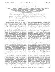
2. <strong>MILA</strong> <strong>Infrared</strong> <strong>Lamp</strong> <strong>Heating</strong> Furnace<br />
The heating furnace uses a heating system, in which infrared lamps are fixed at<br />
the focus of a parabolic reflector. The emitted IR rays converge in parallel<br />
within the iso-thermal zone of the furnace where the sample is located. The<br />
lamps are available in two types: a near infrared lamp (100 V, 1 kW/piece)<br />
with high energy density that can heat the sample to a high temperature<br />
efficiently within a short time, or a far-infrared lamp (100 V, 250 W/piece)<br />
suited to uniform heating. Being sealed in a quartz glass tube, these infrared<br />
lamps generate no gas from the heating element and allow clean heating. The<br />
furnace body is made of aluminum and is cooled with water to allow heating<br />
to a high temperature.<br />
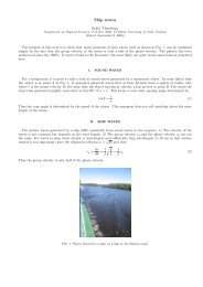
• <strong>MILA</strong> heating sample assembly<br />
As shown in Fig. 1, the sample assembly is sealed air-tightly with O-rings<br />
on both ends of a transparent quartz glass tube and is fixed to the<br />
water-cooled aluminum alloy flange. The sample, set on the transparent<br />
quartz glass holder, is accommodated in the transparent quartz glass tube<br />
and is heated with the infrared lamp (near-infrared, far-infrared) outside of<br />
the transparent quartz glass tube.<br />
The near-infrared lamps emit IR rays in the 0.9 um range. 95% or more of<br />
these rays are transmitted through the transparent quartz glass tube and heat<br />
only the sample by radiation, making this method suitable for high<br />
temperature, rapid heating/cooling processes.<br />
- 2 -
Cooling water<br />
outlet port<br />
Quartz sample<br />
holder<br />
Thermocouple<br />
inlet port<br />
Heat shield<br />
Sample heating<br />
system<br />
<strong>Infrared</strong> lamp<br />
Fig. 1 Sample assembly structural drawing<br />
- 3 -<br />
Sample observation port<br />
O-ring<br />
Sample water-cooling chamber<br />
T<br />
Cooling water inlet port<br />
Evacuation port<br />
Jig stopper<br />
Sample moving<br />
flange axis
3. Evacuation <strong>System</strong> (option)<br />
Ultimate pressure 10 -4 Pa (room temperature no-load pressure at the<br />
pump head)<br />
Air-cooled oil diffusion pump 50 L/sec<br />
Oil rotary pump 20 L/min<br />
Power requirements 100 V, single phase, 0.35 kW<br />
Weight Approx. 16 kg<br />
Outside dimensions 346 mm wide by 316 mm deep by 350 mm high<br />
4. Heated Sample Observation <strong>System</strong> (option)<br />
Components: CCD camera, macro lens, XYZ adjustment stage<br />
Observation port<br />
CCD camera effective pixel/390,000 pixels<br />
Magnification on the monitor/maximum 150x (on 17” monitor)<br />
17” color monitor<br />
5. Gas Flow Unit (option)<br />
Floating ball type flow meter (fixed to the side of the basic unit with metal<br />
bracket)<br />
* The gas species and gas flow rate are to be specified before fabrication<br />
(Up to maximum 3 units can be added.)<br />
6. Cooling Water Circulation Unit (option)<br />
Cooling capacity 1700/1900 kCal/hr<br />
Power requirements 200 V, three phase, 50/60 Hz<br />
Power capacity 3.5 kVA<br />
Weight Approx. 85 kg<br />
Outside dimensions 550 mm wide by 450 mm deep by 950 mm high<br />
7. Cooling Water Flow Switch (option)<br />
Installed at the furnace cooling water outlet port.<br />
If the cooling water is shut off or its flow rate becomes lower than the setting,<br />
the heating furnace is shut down.<br />
- 4 -
8. Front panel of <strong>MILA</strong><br />
Thermocouple<br />
Sample movement flange<br />
- 5 -<br />
<strong>Heating</strong> sample<br />
assembly<br />
OMRON E5AR<br />
HEAT lamp/HEAT ON SW<br />
RESET SW<br />
Photo 1 <strong>MILA</strong> front panel
9. Rear Panel of <strong>MILA</strong><br />
Thermocouple output terminal for<br />
recorder<br />
Fuse socket<br />
Flow switch terminal<br />
Auxiliary<br />
terminal<br />
Acryl cover<br />
200 VAC power input<br />
Earth<br />
terminal<br />
- 6 -<br />
GAS INLET(1/4 inch)<br />
Photo 2 Rear panel of <strong>MILA</strong><br />
T<br />
Evacuation<br />
discharge port<br />
(NW25)<br />
T<br />
GAS OUTLET<br />
(1/4 inch)<br />
Cooling water<br />
inlet/outlet port<br />
6mm ID x 11mm OD braided<br />
hose joint
10. Names and Functions of Components<br />
10.1 Main Controller Front Panel<br />
①<strong>System</strong> Main power<br />
② Sample outlet port<br />
⑤ HEAT/RESET button<br />
- 7 -<br />
③ Interlock light<br />
④ Temperature controller(E5AR)<br />
① Main power<br />
Turning on the mains power switch sends power to the temperature<br />
controller.<br />
② Sample outlet port<br />
Loosen the thumb screws and place the sample in the quartz sample holder<br />
③ Interlock light<br />
TS_SW light and FLOW_SW light. The light is on when there<br />
is no trouble<br />
If either interlock light is off, check the cooling water flow<br />
switch or other interlock (both are options). With the standard<br />
model (when no option is provided), FLOW SW and AUX<br />
terminals on the rear of the system are shorted with jumper<br />
wires.
Factory setting<br />
FLOW SW<br />
If the optional cooling water flow switch was<br />
ordered, connect the cooling water flow<br />
switch cable here.<br />
AUX<br />
If any other interlock is added as option,<br />
connect it to this switch.<br />
④ E5AR temperature controller<br />
Refer to the E5AR-T program type digital temperature controller for how to<br />
operate the temperature controller.<br />
⑤ HEAT/RESET button<br />
HEAT button<br />
Pressing the HEAT light turns the light red if the interlock is<br />
normal. <strong>Heating</strong> can be started with RUN on the temperature<br />
controller when the HEAT light is on. If the light does not come on<br />
when pressed, check the interlock (cooling water, AUX).<br />
If the HEAT light does not come on<br />
① Cooling water interlock faulty (FLOW switch terminal block<br />
on the rear of the system)<br />
Check cooling water.<br />
If the optional flow switch was not ordered, it has been<br />
shorted with a jumper.<br />
② Other interlock faulty (AUX terminal block on the rear of the<br />
system)<br />
Check if interlocks are normal.<br />
If optional interlocks have not been ordered, it has been<br />
shorted with a jumper.<br />
③ Overheating fault, thermocouple burnout<br />
If SUB2 is lit in excess of the overheating set value on the<br />
temperature controller, the HEAT light goes off. Check the<br />
overheating set value. Also check if the thermocouple is<br />
intact.<br />
Check if the sample outlet port is open.<br />
RESET button<br />
- 8 -
* In case of emergency (to stop heating), heating can be stopped by pressing<br />
the RESET button. (The program does not stop, but power to the IR lamps<br />
is switched off.)<br />
- 9 -
10.2 Rear Panel of Temperature Controller<br />
③ Terminal block<br />
① 200V AC input<br />
① Power input<br />
② Earth<br />
③ Terminal blocks<br />
- 10 -<br />
② Earth<br />
④USB communication port<br />
Connect t (200 VAC, single phase, 20 A or more) to the<br />
<strong>MILA</strong><strong>5000</strong> AC200V INPUT terminal block.<br />
* When connecting, be sure to tighten the screws firmly<br />
to avoid of this connector. Loose screws can be a<br />
fire hazard.<br />
Connect the earth wire (Ground wire) as shown in the<br />
photo.
1. TC (+) (-)<br />
The Thermocouple voltage is output to these terminals, which can be<br />
used to connect a device to read or record the thermocouple voltage.<br />
2. F S (Flow Switch)<br />
Connect the cooling water flow switch cable. (option)<br />
If the flow switch was not ordered, it has been shorted before shipment<br />
from the factory with a jumper wire.<br />
3. AUX<br />
Connect the cable for other interlock (only when the optional interlock<br />
was added). (Shorted before shipment from the factory.)<br />
④ USB port<br />
Used when programming and operation of the <strong>MILA</strong> unit is via<br />
PC.<br />
* For the communication with the personal computer, refer to<br />
the operation manual for the <strong>MILA</strong> control software<br />
CX-THERMO.<br />
- 11 -
11. Installing the Sample Holder<br />
Photo Sample holder and heat shield<br />
- 12 -<br />
Quartz sample<br />
holder<br />
Heat shield<br />
① Pass the heat shield through the sample holder.<br />
Set the heat shield between the heat shield stoppers of the sample holder<br />
* Never touch the quartz sample holder with bare hands. If the quartz glass<br />
is heated with water or oil on it, it will become devitrified when heated<br />
(become milky white in appearance and lose its IR transparency!<br />
If it becomes stained with water or oil, clean it with alcohol. Wear<br />
latex or nitrile gloves to prevent finger oils from contaminating the quartz<br />
surfaces.<br />
Sample stage<br />
Photo Thermocouple set in position<br />
T<br />
Pt ribbon on the end of thermocouple<br />
Sample holder<br />
fixture
- 13 -
② Pass the thermocouple fixed to the loading door flange through the center<br />
tube of the sample holder rod and pull the platinum ribbon end of the<br />
thermocouple through to the sample dish area.<br />
③ Adjust the sample holder so that the stage is set in a horizontal position.<br />
* Do not tighten the sample holder metal fixture excessively. The quartz<br />
glass sample holder may be damaged. Just tightening the setscrew until<br />
the setscrew does not move will do. Finger tight only!<br />
* Damage caused by excessive tightening is not covered by warranty.<br />
- 14 -
Specifications of E5AR-T Temperature Controller<br />
Input unit<br />
• High speed sampling<br />
• High accuracy/high resolution<br />
Sampling : 50 ms<br />
period<br />
Accuracy : Thermocouple 1 digit or less ( 0.1% PV or 1 C,<br />
whichever greater)<br />
Platinum 1 digit or less ( 0.1% PV or 0.5 C,<br />
thermoresistance whichever is greater)<br />
Analog ( 0.1% full scale) 1 digit or less<br />
(Refer to Appendix: Specifications for exceptions.)<br />
Input : 1/100 C<br />
resolution<br />
(Pt100: 0.01 C resolution from - 150.00 to 150.00 C)<br />
High speed sampling and high accuracy/high resolution have been realized<br />
simultaneously, allowing control with high accuracy high speed response<br />
according to application.<br />
• Multi-input<br />
An abundant input range from temperature input to analog input is available.<br />
Temperature : Thermocouple K, J, T, E, L, U, N, R, S, B, W<br />
input<br />
Platinum thermoresistance Pt100<br />
Analog input : Current input 4 to 20 mA, 0 to 20 mA<br />
Voltage input 1 to 5 V, 0 to 5 V, 0 to 10 V<br />
• Multi-point input<br />
<strong>Model</strong> E5AR-T is available in 2-input type and 4-input type and <strong>Model</strong><br />
E5ER-T is available in 2-input type.<br />
Control unit<br />
• Program<br />
Up to maximum 32 programs can be created, in which the target value, time,<br />
PID group No., alarm group No., weight width higher/lower limit values,<br />
number of program repeat times and program link destination No. are<br />
registered.<br />
The target value, time, wait valid, and segment output can be set for each<br />
segment.<br />
• PID group<br />
- 15 -
Setting data for PID control (PID values, variable control limit value, and<br />
automatic selection range higher limit value) can be created up to maximum 8<br />
groups.<br />
Each PID group directly specifies with the PID group No. in the program, but<br />
also can automatically select the PID group that changes over according to the<br />
current value, deviation and target value.<br />
• Abundant control modes and control functions<br />
One unit of the 2-input type or 4-input type permits coordinated operation. The<br />
slave type controller that has been necessary is no longer necessary.<br />
The position proportional type permits selection of floating control and closed<br />
control. In floating control, position proportional control can be made without<br />
using a potentiometer.<br />
Output unit<br />
• Multi-output<br />
Multi-output compatible with current output and voltage output (pulse) is<br />
available.<br />
• High resolution<br />
Resolution of current output<br />
0 to 20 mA : Approx. 54,000 resolution<br />
4 to 20 mA : Approx. 43,000 resolution<br />
- 16 -
• Table of Inputs<br />
Set value Input type<br />
( C)<br />
Set range<br />
( F)<br />
1 Pt100 (1) -200.0 to 850.0 -300.0 to 1500.0<br />
2 Pt100 (2) -150.00 to 150.00 -199.99 to 300.00<br />
3 K (2) -20.0 to 500.0 0.0 to 900.0<br />
4 J (1) -100.0 to 850.0 -100.0 to 1500.0<br />
5 J (2) -20.0 to 400.0 0.0 to 750.0<br />
6 T -200.0 to 400.0 -300.0 to 700.0<br />
7 E 0.0 to 600.0 0.0 to 1100.0<br />
8 L -100.0 to 850.0 -100.0 to 1500.0<br />
9 U -200.0 to 400.0 -300.0 to 700.0<br />
10 N -200.0 to 1300.0 -300.0 to 2300.0<br />
11 R 0.0 to 1700.0 0.0 to 3000.0<br />
12 S 0.0 to 1700.0 0.0 to 3000.0<br />
13 B 100.0 to 1800.0 300.0 to 3200.0<br />
14 W 0.0 to 2300.0 0.0 to 4100.0<br />
15 4 to 20 mA One of the following ranges is displayed according to scaling.<br />
16 0 to 20 mA -19999 to 99999<br />
17 1 to 5 V -1999.9 to 9999.9<br />
18 0 to 5 V -199.99 to 999.99<br />
19 0 to 10 V -19.999 to 99.999<br />
-1.9999 to 9.9999<br />
[Miscellaneous]<br />
Communicating function<br />
The temperature program and other important data can be transferred from the<br />
personal computer to the temperature program via USB cable and monitored<br />
during operation by using the supplied software CX-thermo. Refer to the<br />
CX-thermo manual for the software specifications.<br />
- 17 -
Names of components of temperature controller E5AR<br />
Names of components on front panel<br />
• <strong>Model</strong> E5AR-T<br />
Action indicating light<br />
Channel display<br />
Program status display<br />
Bar graph<br />
Action indicating light<br />
Function key 1/run/reset key<br />
Function key 2<br />
Level key<br />
Initial window<br />
①Indicating<br />
light<br />
Components on initial window<br />
① Indicating light<br />
SUB1: SUB1 lights when heating is started normally.<br />
- 18 -<br />
1st display<br />
2nd display<br />
3rd display<br />
UP key<br />
DOWN key<br />
MODE key<br />
② 1st display<br />
③ 2nd display<br />
④ 3rd display
SUB2: SUB2 lights if the overheating interlock is actuated. (SUB1 goes off<br />
simultaneously if SUB2 illuminates.<br />
② 1 st display<br />
Displays the actual thermocouple temperature.<br />
③ 2 nd display<br />
Displays the programmed temperature.<br />
④ 3 rd display<br />
Displays the program pattern No. and step.<br />
How to input the temperature program<br />
The following program is set.<br />
Temperature<br />
o ( C)<br />
SP start<br />
- 19 -<br />
Action after end of<br />
operation "Continue"<br />
* The method of inputting the program above is described below as an example.<br />
Temperature program inputting procedure<br />
(1) Specify a PTN No. using the PF2 key. PTN1 is specified in the photo<br />
below.<br />
(2) Create a temperature program.<br />
1. Press the Level key in the initial window to<br />
transfer control from “Operation Level” to<br />
“Program Setting Level”. Specify program No.<br />
“1” with “prgm: Edit program”.<br />
Up to maximum 32 programs can be created.<br />
A total of 256 steps can be registered.<br />
(Maximum 16 programs can be created (No. 1<br />
to No. 16) and maximum 16 steps can be<br />
input.)<br />
To change the maximum input number of
programs, use the supplied software<br />
CX-thermo.<br />
2. Press and hold the Mode key for less than a<br />
second and select “s-no: number of segments”.<br />
Press the Up key and set an arbitrary number<br />
of segments. The number of segments is “8” in<br />
the case of the example pictured at the left.<br />
“Segment” is the total number of steps of the<br />
temperature program.<br />
3. Press the Mode key, select “seg.n: Edit<br />
segment” and press the UP key to select “1”<br />
from “end”.<br />
4. Press the Mode key and select “sp:Segment target<br />
value”. Press the Up key to set the target value at<br />
“200.0”.<br />
(Set the actual ultimate target temperature.)<br />
- 20 -
5. Press the Mode key twice and select “time:<br />
Segment time”. Press the Up key to set time at<br />
“1.00”.<br />
(Input the actual target elapse time of each step.)<br />
Press the Mode key to display the Pr window, but<br />
it is not necessary to input. Input will be<br />
invalidated. The input value is 0.<br />
Pr window<br />
In heating with this temperature controller, time<br />
or gradient is set. If gradient is set, the Pr value<br />
will be validated.<br />
Time has been set before shipment from the<br />
factory, so that it is not necessary to input it in the<br />
Pr window.<br />
6. Press the Mode key and select “wait: Wait<br />
effective”. is turned “off”.<br />
7. Press the Mode key 3 times to return control to<br />
“segn: Edit segment” The segment No.<br />
automatically becomes “2”<br />
(Repeat this step up to the last segment. Up to<br />
segment 6 with the above program.<br />
8. Press the Mode key and select “sp: Segment target value”. Press the UP key<br />
to set the target value at “800.0”.<br />
9. Press the Mode key twice and select “time: Segment time”. Press the Up<br />
key to set time at “1.30”.<br />
- 21 -
10. Press the Mode key and select “wait: wait effective”. Turn it “off”,<br />
11. Press the Mode key three times to revert to “segn: Edit segment”. The<br />
segment No. is automatically set at “3”.<br />
When input of temperature and time is completed to the last segment, the<br />
window displays [END], thereby temperature program input being<br />
completed.<br />
S U B 1<br />
The action indicating light S U B 1 com es on w hen heating is<br />
started (w hen P F1 R U N has started). H ow ever, heating does<br />
not start if S U B 2 is lit and the H EA T light on the front panel<br />
of the instrum ent is off.<br />
C heck the follow ing item s.<br />
① A larm set value (confirm ation of overheating set<br />
tem perature) S U B 2 com es on.<br />
② C heck if the [FLO W S . W ] term inal on the rear of the<br />
instrum ent is shorted. -> The H EA T light on the front panel<br />
of the instrum ent<br />
③ If the flow sw itch unit w as (supplied) ordered, check if<br />
cooling w ater is flow ing norm ally and the cooling w ater flow<br />
rate is in excess of the flow sw itch set value. -> H EA T light<br />
on the front panel of the instrum ent<br />
* Refer to the OMRON E5AR-T User’s <strong>Manual</strong> for more information about<br />
the method of inputting the temperature program.<br />
- 22 -
How to input (register) PID values (when manually inputting a value)<br />
PID values can be registered up to a total of 8 patterns.<br />
How to register<br />
1. Press the Level key 4 times in the initial<br />
window.<br />
2. Specify a PID No to use with the UP/DOWN<br />
key.<br />
3. Press the Mode key once.<br />
4. Input PID values.<br />
5. Input I value.<br />
- 23 -
6. Input D value.<br />
To make heating test<br />
① Press the PF2 key to select a program pattern to use.<br />
② Holding down the PF1 key starts heating. To stop heating, hold down the<br />
PF1 key again.<br />
Specify PID values and alarm to use during heating test.<br />
Input a PID No. to use.<br />
Input a PID No. to use, 0 to 8.<br />
In the photo at left, PID No. 1 is specified.<br />
(PID has a total of 8 patterns.)<br />
Input an alarm to use No. 1 to 4.<br />
Up to 4 alarm Nos. can be registered in total.<br />
In the photo at left, alarm No. 1 is specified.<br />
(Example) Alarm 1 = 1200 C<br />
Alarm 2 = 1000 C<br />
Alarm 3 = 800 C<br />
Alarm 4 = 500 C<br />
If the alarm setting is registered as shown above<br />
and alarm No. 1 is specified, heating to 1200 C has<br />
been set.<br />
Refer to the alarm temperature setting method.<br />
- 24 -
Using PID pattern<br />
• When running a heating/holding program with one PID<br />
① Press the Level key in the initial window.<br />
② Press the Mode key 3 times.<br />
③ Specify a PID pattern No. to use. Up to a total of 8 patterns of PID can be<br />
registered.<br />
* Holding down the PF1 (RUN) key starts heating test using the specified<br />
PID<br />
Basically, once PID values are calculated by auto tuning, temperature can be<br />
increased/held with one PID , except special temperature recipe.<br />
Procedure<br />
(1) Set sample.<br />
(2) Start heating.<br />
(3) <strong>Heating</strong> holding Auto tuning during holding<br />
(4) PID values being used are automatically calculated.<br />
- 25 -
Auto tuning (AT)<br />
Press the Level key twice.<br />
Change display ② from “OFF” to “0” or<br />
“1 to 8” with the up/down key to start AT.<br />
If AT is started by specifying “0”, the<br />
display ① blinks and the PID group No.<br />
now being used appears at display ②.<br />
With completion of AT, the display ①<br />
stops blinking.<br />
If “1 – 8” is specified, the PID value of the<br />
specified PID group No. is changed.<br />
For more information about the method of<br />
AT operation, refer to the OMRON<br />
E5AR-T User’s <strong>Manual</strong>.<br />
AT (Auto Tuning)<br />
• AT automatically sets optimum PID constants for the target value when<br />
executing. This system employs the limit cycle method, which finds the<br />
characteristics of an object to control by changing the control variable.<br />
① Set program ② Program executed ③ AT start<br />
④ AT end ⑤ Time<br />
• During AT, segment operation, such as change of set data, hold/hold resetting,<br />
advance, back, etc., cannot be performed.<br />
• AT will be stopped if “Run/Reset” is “Reset” (when “action at resetting” is<br />
“control stop”) or is set in the manual mode. AT cannot be executed during<br />
resetting (when the “action at reset” is “control stop”) or in the manual mode,<br />
• When executing AT, specify “0” or when executing AT by specifying the PID<br />
group No., specify “1 to 8”.<br />
• The result of AT is reflected in “Proportional band”, “Integral time” and<br />
“Differential time” of the PID group No. specified at AT of “PID set level”.<br />
When “Action at reset” is “Constant value control”, the action is as follows.<br />
• If “Run/Reset” is set at “Reset” during AT execution during run, the current<br />
target value is changed over to a constant value SP after AT has ended.<br />
- 26 -
• If AT is executed during resetting and “Run/Reset” is set at “Run” during AT<br />
execution, the set program will start after AT has ended for the set value SP.<br />
• Description of AT Actions<br />
Changing “AT execution/stop” from OFF to 0 starts AT.<br />
During execution, the 1 st display of “Execute AT/Stop”<br />
blinks and the 2 nd display shows the PID group No.<br />
currently being used for control. With completion of AT,<br />
“Execute AT/Stop” is turned off and the display stops<br />
blinking.<br />
AT is executed and the following display appears<br />
1 st display: Blinking display that shows that AT is being executed.<br />
2 nd display: The display changes over to the selected PID group No.<br />
To stop AT, specify “off : Stop AT”.<br />
If control is shifted to operation level during AT execution<br />
and “Current value/Target value” is set, the 2 nd display<br />
blinks, indicating that AT is being executed.<br />
• During execution of AT, “Communication write”,<br />
- 27 -
“Run/Reset”, “AT execution/stop”, and “Auto/<strong>Manual</strong>”<br />
can be changed. Other set data cannot be changed.<br />
• If Reset is set with “Run/Reset” during execution of AT,<br />
AT is stopped to stop operation if “Action at Reset” is<br />
“Control Stop”. Even if Run is set with “Run/Reset”<br />
again, AT does not restart.<br />
• If any input fault occurs during execution of AT, AT is<br />
stopped and is executed again by resetting input error.<br />
- 28 -
How to set overheating (alarm)<br />
① Press the Level key 3 times in the initial<br />
window.<br />
The photo at left shows, pattern No. 1<br />
overheating setting.<br />
② Press the Mode key.<br />
Select the alarm pattern No. with the<br />
UP/DOWN key.<br />
(Alarm can be set up to 4 patterns.)<br />
The photo at left shows the overheat<br />
setting of alarm setting temperature No. 1<br />
Press the Mode key.<br />
Input the overheat setting temperature with the<br />
UP/DOWN key.<br />
* On the photo at left, the overheat setting<br />
temperature is 0 C.<br />
SUB2 lights because the overheat setting<br />
value is below room temperature (below<br />
PV value). The overheat interlock is<br />
actuated.<br />
Input a temperature arbitrarily.<br />
If the overheat setting temperature is<br />
exceeded during heating test, heating will<br />
be stopped and the lamp is turned off.<br />
Simultaneously with heating being<br />
stopped, SUB1 goes off and SUB2 comes<br />
- 29 -
on. <strong>Heating</strong> cannot be made if the actual<br />
temperature is in excess of the overheat<br />
setting value.<br />
<strong>Heating</strong> is ready when the creation of the temperature program, registration<br />
and specification of PID, and setting and specifying of overheating are<br />
completed. <strong>Heating</strong> can be started by holding down the PF1 key for a moment.<br />
* For emergency stop and heating stop, hold down the PF1 key or press the<br />
RESET button.<br />
* If the set values are lost (unknown) during input (to revert to the initial<br />
window), press the Level key several times to revert to the initial window.<br />
- 30 -
Other functions<br />
How to set thermocouple<br />
Hold down the Level key. The window is changed over.<br />
Set the thermocouple with the<br />
UP/DOWN key.<br />
Example of setting<br />
① K thermocouple 2<br />
② R thermocouple 11<br />
Upon completion of setting, hold down<br />
the PF2 key to revert to the initial<br />
window.<br />
Refer to the OMRON E5AR-T User’s<br />
<strong>Manual</strong> for more information about the<br />
thermocouple setting.<br />
Changing over AUTO heating and MANU heating<br />
Press the Mode key 12 times in the initial window.<br />
Change over AUTO or MANU with the up/down key.<br />
The mode is changed over to MANU several seconds after MANU is selected.<br />
AUTO: <strong>Heating</strong> by a specified temperature program<br />
MANU: Regulate the output with the UP/DOWN key.<br />
If MANU is selected, control the output with the UP/DOWN key. (Output can<br />
be set during and before heating.)<br />
To select the AUTO mode again, press the Mode key 12 times in the window<br />
shown below and select AUTO with the UP/DOWN key.<br />
The photo shows MANU 100% output.<br />
- 31 -
Setting the unit of program time<br />
Hold down the Level key in the initial window.<br />
Press the Mode key.<br />
Press the Mode key 7 times in the window at left.<br />
Set “hour, minute”, “minute, second” and “minute,<br />
second, 100 millisecond” using UP/DOWN key.<br />
In the window at left, “minute, second” are set.<br />
In the window at left, “hour, minute” are set.<br />
In the window at left, “minute, second, millisecond”<br />
are set.<br />
* For more information about how to set the unit<br />
of program time, refer to the OMRON<br />
E5AR-T Users <strong>Manual</strong>.<br />
- 32 -
<strong>Manual</strong> Setting<br />
For manual setting of PID constants, set values in “Proportional Band”,<br />
“Integral Time” and “Differential Time”.<br />
[Supplement]<br />
• If control characteristics are already known, set PID constants directly. Set PID<br />
constants with “Proportional Band”, “Integral Time” and “Differential Time”.<br />
• Set PID constants I (integral time) and D (differential time) at 0 to make<br />
proportional action. The manual reset value has been set at 50% as the initial<br />
value, so that the center of the proportional band is the target value.<br />
When P (proportional band) is changed<br />
Increase Target value<br />
Decrease Target value<br />
When I (integral) time is changed<br />
Increase Target value<br />
Decrease Target value<br />
- 33 -<br />
Slow rise and longer settling time,<br />
but no overshooting<br />
Overshooting and hunting, but set<br />
value is attained sooner to stability.<br />
Longer time before target value is<br />
attained<br />
Longer settling time,but smaller<br />
hunting, overshoot and undershoot<br />
Overshoot and undershoot occur.<br />
Hunting occurs.<br />
Shorter rise time.<br />
When differential time (D) is changed<br />
Increase Target value Shorter overshoot and undershoot<br />
settling time, but minor hunting in<br />
its own change.<br />
Decrease Target value Higher overshoot and undershoot<br />
and more time is required to restore<br />
the target value.
• Application<br />
Changing PID at each step with a multi-step heating/holding program<br />
Multi-step PID: PID is changed over depending on a specified temperature<br />
range.<br />
* Basically, temperature can be controlled with one PID by using auto tuning.<br />
Conduct auto tuning first.<br />
Automatic selection of PID group<br />
PID group Automatic selection range higher limit value<br />
1 200.0<br />
2 400.0 PV (current value)<br />
3 500.0<br />
4 600.0<br />
5 700.0<br />
6 800.0<br />
7 1000.0<br />
8 1300.0 Internal fixed value<br />
: 999.9% FS<br />
In the example above (when “PID group automatic selection data” is “PV”),<br />
the following PID values are effective.<br />
When PV 200.0 C : PID group No. 1<br />
When 200.0
Set data Set range Unit Initial value<br />
PID group No. 0: Automatic selection<br />
1 to 8: PID group No.1 to 8<br />
- 0<br />
PID group No. 1 – 8<br />
automatic selection range<br />
higher limit value<br />
- 19999 to 99999 EU 1450.0<br />
PID group automatic selection<br />
data<br />
0: PV, 1: DV, 2: SP - 0: PV<br />
PID group automatic selection<br />
hysteresis<br />
0.10 to 99.99 %FS 0.50<br />
① Press the Level key 4 times in the initial window.<br />
② Press the <strong>Model</strong> key 6 times.<br />
③ Specify PID No. at 0.<br />
Press the Level key 4 times in the initial<br />
window.<br />
The window at left appears.<br />
Specify the PID No.<br />
(Example)<br />
PID group Automatic selection range higher limit value<br />
1 200.0<br />
2 400.0 PV (current value)<br />
3 500.0<br />
4 600.0<br />
5 700.0<br />
6 800.0<br />
7 1000.0<br />
8 1300.0 Internal fixed value<br />
: 999.9 FS<br />
- 35 -
Set the temperature range of PID. No.1.<br />
For example, input 200 C in the table.<br />
Input PID. No. 2 to 8 in the same manner as<br />
above.<br />
For more information about how to change over PID, refer to the OMRON<br />
E5AR Users’ <strong>Manual</strong>.<br />
* Basically, temperature can be controlled with one PID constant. Change<br />
PID at each step only in a special case. Calculate PID by auto tuning.<br />
- 36 -
Other functions that are used often<br />
Hold<br />
Initial window in heating Press Mode key twice Change over to ON with<br />
UP/DPWN key.<br />
HOLD light comes on at<br />
HOLD.<br />
To terminate HOLD, turn off HOLD with the UP/DOWN key again.<br />
ADVANCE<br />
Initial window in heating Press MODE key twice. Change over to ON with<br />
UP/DOWN key.<br />
STEP is changed over to the next step simultaneously with ON.<br />
For more information about the settings of each component, refer to <strong>Model</strong><br />
E5AR-T Users’ <strong>Manual</strong> for the Program Type Digital Controller<br />
- 37 -