Journal of Accident Investigation
Journal of Accident Investigation
Journal of Accident Investigation

Create successful ePaper yourself
Turn your PDF publications into a flip-book with our unique Google optimized e-Paper software.
Fractographic Examination Procedures and Challenges<br />
For most common airplane structural metals, visual<br />
inspection or low-power magnification is <strong>of</strong>ten sufficient to<br />
determine fracture mechanism and direction. For metals, the<br />
fracture plane, surface roughness, radial marks, chevrons, shear<br />
lips, and general deformation all provide macroscopic clues to<br />
the fracture mechanisms, direction <strong>of</strong> fracture propagation,<br />
and relative motion <strong>of</strong> mating surfaces. Preexisting cracks in<br />
metals <strong>of</strong>ten show staining or changes in color associated with<br />
corrosion. 4 Using these clues, experienced investigators can<br />
examine large areas <strong>of</strong> damaged structure relatively quickly to<br />
identify fracture origins and areas requiring closer inspection.<br />
However, composites by their nature present their own<br />
set <strong>of</strong> challenges. Visual clues to preexisting fractures, such<br />
as flat fracture surfaces with curving boundaries or staining<br />
from corrosion, which are easy to see in structural metals, are<br />
in general not as visible in composites. Furthermore, visual<br />
cues to fracture propagation direction that are sometimes<br />
apparent in composite structures, such as crack branching in<br />
translaminar fractures (fractures that break fibers) or banding<br />
in delaminations (fractures between layers), were not apparent<br />
in many <strong>of</strong> the fractures <strong>of</strong> interest on the accident airplane.<br />
Because visual cues were not present in many <strong>of</strong> the fractures,<br />
3 Fractography is the examination <strong>of</strong> fracture surfaces and adjacent areas<br />
to determine conditions that caused the fracture. See ASM Handbook,<br />
Volume 11: Failure Analysis and Prevention, eds. W.T. Becker and R.J.<br />
Shipley, ASM International, 2002.<br />
4 K. Mills and others, eds., Fractography, ASM Handbook Vol. 12 (ASM<br />
International: Metals Park, Ohio, 1987).<br />
MATERIALS EXAMINATION OF THE VERTICAL STABILIZER FROM AMERICAN AIRLINES FLIGHT 87<br />
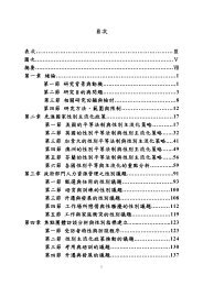
two 45-degree fabric layers<br />
two zero-degree tape layers<br />
stringer outer flange layers<br />
(zero-degree tape)<br />
Figure 3. Microstructure <strong>of</strong> sample RS1. The cross-section shown is in a plane that is oriented parallel to the<br />
plus or minus 45-degree fiber direction. Fiber and void content were determined using computer optical image<br />
analysis <strong>of</strong> polished micrographs. The layup in each sample was determined from optical micrographs <strong>of</strong> the<br />
specimens that were assembled into mosaics like the one shown here.<br />
the composite fractures in the accident airplane required an<br />
especially time-consuming examination because the area to<br />
be examined using high magnification was substantially larger<br />
than what is typically required for overstress fractures <strong>of</strong> similar<br />
metal structures.<br />
Investigators first conducted a visual inspection <strong>of</strong> the<br />
translaminar fractures and delaminations. This examination<br />
included mapping the fractures to help determine fracture<br />
propagation directions from crack branching patterns, recording<br />
features indicating translaminar fracture under tension or<br />
compression, and, in the delaminations, identifying any visual<br />
cues to changes in fracture mechanism or mode.<br />
Using results <strong>of</strong> the visual examination as a guide, investigators<br />
used scanning electron microscopy (SEM) to determine the<br />
fracture mechanism and fracture propagation direction on the<br />
translaminar fractures and on the delamination surfaces, and<br />
to identify the layers involved, fracture mechanisms, modes <strong>of</strong><br />
fracture, and propagation directions. The SEM examination also<br />
enabled investigators to distinguish between fatigue fractures<br />
and preexisting cracks, which may appear similar during a visual<br />
examination. Results <strong>of</strong> the SEM examination were used to<br />
check construction <strong>of</strong> the vertical stabilizer and rudder against<br />
the manufacturing drawings and to determine how the fractures<br />
related to the loading <strong>of</strong> the overall structure.<br />
Two samples, one from each <strong>of</strong> the two large delaminations,<br />
were not cleaned, and were examined first in order to explore<br />
R.J. Kar, “Atlas <strong>of</strong> Fractographs,” in Composite Failure Analysis Handbook<br />
Volume 2: Technical Handbook (Northrop Corporation, Aircraft Division,<br />
1992).<br />
NTSB JOURNAL OF ACCIDENT INVESTIGATION, SPRING 2006; VOLUME 2, ISSUE 1 13