Journal of Accident Investigation
Journal of Accident Investigation
Journal of Accident Investigation

You also want an ePaper? Increase the reach of your titles
YUMPU automatically turns print PDFs into web optimized ePapers that Google loves.
MATTHEW R. FOX, CARL R. SCHULTHEISZ, JAMES R. REEDER, AND BRIAN J. JENSEN<br />
Analysis <strong>of</strong> the flight data recorder revealed that the airplane<br />
had performed a series <strong>of</strong> yawing maneuvers in the seconds before<br />
separation <strong>of</strong> the vertical stabilizer, and that the separation <strong>of</strong><br />
the vertical stabilizer occurred while the airplane was pointed to<br />
the left <strong>of</strong> its flight path. This orientation would have produced<br />
a bending moment on the vertical stabilizer, leading to tension<br />
on the right-side attachments and compression on the left.<br />
Most <strong>of</strong> the separated pieces <strong>of</strong> the vertical stabilizer and<br />
rudder were recovered from the water <strong>of</strong> Jamaica Bay, some<br />
distance from the main crash site. The vertical stabilizer was<br />
largely intact, and had separated from the fuselage by fractures<br />
at the lower end where it had been connected to the fuselage.<br />
Although a detailed examination <strong>of</strong> the rudder was completed<br />
during the accident investigation, early indications from the<br />
performance analysis <strong>of</strong> the flight recorder data indicated<br />
that the rudder performed as designed through the accident<br />
sequence until the vertical stabilizer separated from the fuselage,<br />
and loads analysis indicated that the vertical stabilizer would<br />
fail before the rudder. Thus, investigators determined that<br />
the rudder failure was secondary to the failure <strong>of</strong> the vertical<br />
stabilizer. As part <strong>of</strong> the overall investigation into the accident,<br />
investigators examined and tested the composite materials <strong>of</strong><br />
the vertical stabilizer and conducted a detailed examination <strong>of</strong><br />
the fractures in the vertical stabilizer to determine the failure<br />
mechanism and direction <strong>of</strong> fracture propagation, where<br />
possible. The possibilities <strong>of</strong> pre-existing damage, fatigue<br />
cracking, or inadequacies in the manufacturing process were<br />
also addressed.<br />
Using accident loads derived from analysis <strong>of</strong> recorded flight<br />
data, three lug tests were conducted on vertical stabilizer aft lugs<br />
from an unused skin panel and from another airplane. Fracture<br />
patterns for these three test specimens were compared to the<br />
corresponding structure on the accident airplane.<br />
This paper describes the structure <strong>of</strong> the vertical stabilizer, the<br />
results <strong>of</strong> the materials testing and microstructural examination,<br />
fractography <strong>of</strong> the vertical stabilizer, and how the results led<br />
investigators to understand the failure. The paper also presents<br />
fractographic examination results for the three lug tests and<br />
significance <strong>of</strong> the fracture features.<br />
DESCRIPTION OF THE STRUCTURE<br />
Development <strong>of</strong> the Airbus A300-600 model began in 1980,<br />
and certification occurred in 1984. The accident airplane was<br />
delivered new to American Airlines in 1988.<br />
Vertical Stabilizer Structure<br />
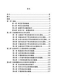
An internal view <strong>of</strong> the vertical stabilizer is shown in figure 1.<br />
The vertical stabilizer for the Airbus A300-600 series airplane<br />
is a stiffened box with removable leading edge fairings and<br />
trailing edge panels. The stiffened box consists <strong>of</strong> two integrally<br />
stiffened skin panels for the left and right sides, spars for the<br />
forward and aft sides, and closure ribs at the upper and lower<br />
ends. The integral stiffeners in the skin panels consist <strong>of</strong><br />
Figure 1. Airbus A300-600 vertical stabilizer construction. The vertical stabilizer and rudder for this model airplane, which has a symmetric airfoil shape,<br />
are 27 feet 3 inches tall and from leading edge to trailing edge, 25 feet wide at the base, and 10 feet 2 inches wide at the tip. The vertical stabilizer and<br />
rudder were made almost entirely <strong>of</strong> composite materials, including the composite lugs at the six main attachment locations for connecting the vertical<br />
stabilizer to the fuselage.<br />
10 NTSB JOURNAL OF ACCIDENT INVESTIGATION, SPRING 2006; VOLUME 2, ISSUE 1