Create successful ePaper yourself
Turn your PDF publications into a flip-book with our unique Google optimized e-Paper software.
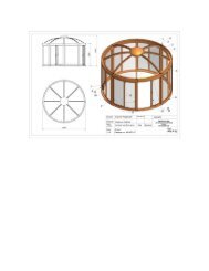
<strong>Riga</strong> <strong>XL</strong> <strong>VI</strong><br />
Assembly Guide<br />
January 31, 2013<br />
<strong>Exaco</strong> Trading Co.<br />
10203 Metropolitan Drive<br />
Austin, Texas 78758-4944<br />
512-407-8500
ABOUT THIS DOCUMENT<br />
This document is an Assembly Guide intended for persons who<br />
have a moderate level of experience building small structures.<br />
It is specific to the six-meter <strong>Riga</strong> <strong>XL</strong> <strong>VI</strong>, but can be applied to<br />
<strong>Riga</strong> <strong>XL</strong> models of other lengths. If you are an experienced <strong>Riga</strong><br />
greenhouse builder, this is the guide for you. Keep these pages<br />
for reference as you proceed with your assembly project.<br />
If you lack experience, or if you wish to approach building your<br />
<strong>Riga</strong> <strong>XL</strong> with all uncertainties resolved, you should download<br />
and study the <strong>Riga</strong> <strong>XL</strong> Owner’s Reference Manual. It is<br />
enhanced for online reading and is packed with valuable<br />
information that can be otherwise gained only from experience.<br />
Once you understand the details you can refer to the Assembly<br />
Guide throughout your project to assure a trouble-free<br />
experience and optimum results.<br />
Download the <strong>Riga</strong> <strong>XL</strong> Owner’s Reference Manual<br />
http://exaco.com/rigamanual/<strong>Riga</strong><strong>XL</strong>RefManual.pdf<br />
2
Table of Contents<br />
ABOUT THIS DOCUMENT .............................................................................................................................. 2<br />
Download the <strong>Riga</strong> <strong>XL</strong> Owner’s Reference Manual .............................................................................. 2<br />
INTRODUCTION ............................................................................................................................................. 6<br />
Welcome to the Exciting World of <strong>Riga</strong> <strong>XL</strong> Ownership ............................................................................. 6<br />
<strong>Riga</strong> <strong>XL</strong> Models .......................................................................................................................................... 6<br />
Available Options ...................................................................................................................................... 6<br />
Tools and Additional Materials You Will Need ......................................................................................... 7<br />
Mandatory tools and materials............................................................................................................. 7<br />
Recommended additional tools ............................................................................................................ 7<br />
Recommended additional materials ..................................................................................................... 7<br />
Tools and materials included in the <strong>Riga</strong> <strong>XL</strong> Essentials Kit.................................................................... 7<br />
RECEI<strong>VI</strong>NG INSPECTION ................................................................................................................................ 8<br />
Take Inventory .......................................................................................................................................... 8<br />
Box 3: Small Parts ..................................................................................................................................... 9<br />
Box 2: Window and Door Profiles .......................................................................................................... 13<br />
Box 1: Profiles for Gables ....................................................................................................................... 14<br />
Box 4: Long Profiles ................................................................................................................................ 15<br />
Arch Bundles 1 and 2: Curved Profiles ................................................................................................... 16<br />
Glazing Bundles 1 and 2 .......................................................................................................................... 17<br />
Options and Accessories ......................................................................................................................... 19<br />
Aluminum foundation frame .............................................................................................................. 19<br />
Shelf kit ............................................................................................................................................... 20<br />
Door extension kit ............................................................................................................................... 20<br />
Adjustable hanger accessory kit? ........................................................................................................ 20<br />
SITE PREPARATION ...................................................................................................................................... 21<br />
Foundation .............................................................................................................................................. 21<br />
Greenhouse dimensions ..................................................................................................................... 21<br />
Substrate elevation ............................................................................................................................. 21<br />
Pier and beam foundation .................................................................................................................. 21<br />
Stem wall foundation .......................................................................................................................... 22<br />
Concrete slab foundation .................................................................................................................... 22<br />
Aluminum foundation frame .............................................................................................................. 23<br />
Isolation membrane ................................................................................................................................ 23<br />
3
STEP-BY-STEP ASSEMBLY GUIDE ................................................................................................................. 24<br />
Summary of Assembly Steps ................................................................................................................... 24<br />
Steps 1 and 2: Assemble the roof windows and doors. ..................................................................... 24<br />
Steps 3 through 10: Build the first gable. ........................................................................................... 24<br />
Steps 11 through 16: Build the roof and side walls. .......................................................................... 24<br />
Step 17: Build the second gable and join it to the side walls. ............................................................ 24<br />
Step 18: Anchor the greenhouse to its foundation. .......................................................................... 24<br />
Steps 19 through 23: Finish the interior and exterior. ....................................................................... 24<br />
Locations of Frame Components ............................................................................................................ 25<br />
Step 1 Roof Windows ............................................................................................................................. 26<br />
Step 2a Upper Doors .............................................................................................................................. 27<br />
Step 2b Lower Doors .............................................................................................................................. 28<br />
Step 3 Gable Floor Profile and Vertical Door Profiles ............................................................................ 29<br />
Step 4 Lower 980 x 944 mm Glazing Panels (1 & 2 of 4)........................................................................ 30<br />
Step 5 Lower Crossbars (1 & 2 of 5m) .................................................................................................... 31<br />
Step 6 T-connectors and Upper 980 by 944 mm Glazing Panels (3 & 4 of 4) ........................................ 32<br />
Step 7 Vertical Middle Profiles ............................................................................................................... 33<br />
Step 8 T-connectors and Upper Crossbars (3, 4, & 5 of 5) ..................................................................... 34<br />
Step 9 Curved & 5-sided Glazing, Straight, K, and Slanted T-connectors .............................................. 35<br />
Step 10 Edge Stay Bars with Pressed-on Plastic Corner Connectors ..................................................... 36<br />
Step 11 Load Screws in the Curved Center Profiles ............................................................................... 37<br />
Step 12 Prepare the Floor Profiles, Crossbars, and Roof Beam ............................................................. 38<br />
Measure and mark the floor profiles and roof beam reinforcement bar ........................................... 38<br />
Prepare the side floor profiles ............................................................................................................ 38<br />
Temporarily prepare the south gable floor profile ............................................................................. 38<br />
Prepare the roof beam reinforcement bar ......................................................................................... 39<br />
Prepare the window opening crossbars ............................................................................................. 39<br />
Step 13 Set the Floor Profiles ................................................................................................................. 40<br />
Step 14 Install the North, East, and West Mounting Brackets .............................................................. 41<br />
Step 15 Set the Roof Beam .................................................................................................................... 42<br />
Step 16 Assemble the Side Walls ........................................................................................................... 43<br />
Introduction to Step 16 ....................................................................................................................... 43<br />
The Window Installation Rule ............................................................................................................. 43<br />
General instructions for Step 16 ......................................................................................................... 44<br />
4
Step 17 Assemble and Set the Second Gable ........................................................................................ 50<br />
Step 18 Install the South Gable Mounting Brackets .............................................................................. 51<br />
Step 19 Install the Lateral Supports ....................................................................................................... 52<br />
Step 20 Install Interior Seals .................................................................................................................. 53<br />
Step 21 Apply Exterior Sealant ............................................................................................................... 54<br />
Step 22 Hang the Doors ......................................................................................................................... 55<br />
Step 23 Install the Window Openers ..................................................................................................... 56<br />
INSTALL OPTIONS ........................................................................................................................................ 57<br />
Install the Optional Shelving ................................................................................................................... 57<br />
Install the 500 Millimeter Door Extension Kit ......................................................................................... 58<br />
Assemble the Aluminum Foundation Frame .......................................................................................... 59<br />
SUPPLEMENTAL INFORMATION ................................................................................................................. 61<br />
All About Anchoring ................................................................................................................................ 61<br />
About installing mounting brackets .................................................................................................... 61<br />
Reasons to install mounting brackets in Step 14 ................................................................................ 61<br />
Reasons to defer mounting bracket installation until Step 18 ........................................................... 61<br />
Installing temporary anchors .............................................................................................................. 61<br />
Anchoring to Concrete: A Special Case .................................................................................................. 62<br />
The problem ........................................................................................................................................ 62<br />
The solution ........................................................................................................................................ 62<br />
FREQUENTLY ASKED QUESTIONS ................................................................................................................ 63<br />
What is the <strong>Riga</strong> <strong>XL</strong> Essentials Kit (REK)? ................................................................................................ 63<br />
Why are ratcheting cargo straps recommended? .................................................................................. 63<br />
Why are additional M6x12 cap screws recommended? ......................................................................... 63<br />
Why would anyone want extra lateral supports? ................................................................................... 63<br />
Why UNC ¼-20 cap screws instead of M6 in the windows, and why extras? ......................................... 64<br />
Why #10 x ¾ inch pan head and #8 x ¾ inch flat head Phillips screws? ................................................. 64<br />
Why preload extra M6x16 screws in each edge stay bar? ...................................................................... 64<br />
Why must a window’s installation path be free of glazing and vertical profiles? .................................. 64<br />
What is a roof beam fitment tool? .......................................................................................................... 65<br />
What if a roof beam fitment tool is not available? ................................................................................. 65<br />
What is a medium modulus neutral cure silicone sealant? .................................................................... 66<br />
5
INTRODUCTION<br />
Welcome to the Exciting World of <strong>Riga</strong> <strong>XL</strong> Ownership<br />
Congratulations on your wise decision to acquire a <strong>Riga</strong> <strong>XL</strong> greenhouse. You have chosen the finest<br />
personal greenhouse available.<br />
This manual will guide you through all aspects of <strong>Riga</strong> <strong>XL</strong> ownership with special emphasis on assembly.<br />
Please read it thoroughly, even before you unpack your shipment, and refer to it throughout the<br />
assembly process. If you follow the instructions and use the recommended tools, you should be able to<br />
easily assemble the greenhouse by yourself.<br />
<strong>Riga</strong> <strong>XL</strong> Models<br />
All <strong>Riga</strong> <strong>XL</strong> models are identical in width and height but there are five different lengths. The model<br />
variations are identified by a Roman numeral suffix equal to the number of 1-meter length sections for<br />
that model.<br />
The <strong>Riga</strong> <strong>XL</strong> <strong>VI</strong> is the standard 6-meter length and is the subject of this manual. Available by special<br />
order are the smaller <strong>Riga</strong> <strong>XL</strong> IV and <strong>Riga</strong> <strong>XL</strong> V, which are 4 and 5 meter lengths respectively. Also<br />
available by special order are the stretch models <strong>Riga</strong> <strong>XL</strong> <strong>VI</strong>I, <strong>Riga</strong> <strong>XL</strong> <strong>VI</strong>II, and <strong>Riga</strong> <strong>XL</strong> IX, which are 7, 8,<br />
and 9 meters long respectively.<br />
The models differ only in the lengths of the horizontal side profiles, the number of side glazing panels<br />
and curved center profiles (arches), the number of roof windows and window openers, and the<br />
quantities of supporting fasteners and seals. The horizontal side profiles for all models are one piece<br />
except those of the <strong>Riga</strong> <strong>XL</strong> IX which are two pieces spliced near the center. The IX model includes a<br />
robust welded aluminum truss for additional support of the roof beam at the splice.<br />
Available Options<br />
Three options and an accessory kit are manufactured for the <strong>Riga</strong> <strong>XL</strong>.<br />
A shelving kit to be installed along one wall.<br />
A door extension kit to lower one door if the greenhouse is built on a stem wall.<br />
An aluminum foundation frame to use if you want your greenhouse at grade level.<br />
Adjustable hanger accessory kit provides attachment points for plant support.<br />
Two shelving kits are required if you want shelving on both sides, and two door extension kits are<br />
required if you want both doors lowered into stem wall openings.<br />
6
Tools and Additional Materials You Will Need<br />
Mandatory tools and materials<br />
8-foot step ladder<br />
#2 Phillips screwdriver<br />
Bubble level 2 to 3 ft. long<br />
Powered screw driver with #2 Phillips bits<br />
Rubber mallet<br />
28 anchor fasteners appropriate for your foundation substrate (must fit 3/8” hole)<br />
Material to erect temporary bracing for the gables and roof beam<br />
Recommended additional tools<br />
10 millimeter socket wrench or nut driver<br />
6-foot step ladder<br />
Work table<br />
At least three sawhorses<br />
Rubber mallet<br />
Industrial quality scissors to cut seal material<br />
At least four clamps such as Irwin “Quick Grip”<br />
Two adjustable hanger accessory kits<br />
Window screen bead roller to help press in window and door seals<br />
10-foot length of ½” EMT electrical metallic tubing (conduit) to use as a window prop<br />
Recommended additional materials<br />
Membrane to isolate the aluminum floor profiles from the foundation substrate<br />
Roll of 1-inch “Scotch blue painter’s tape<br />
Thread lubricant for self-tapping screws (a wax crayon will do)<br />
Additional M6 stainless cap screws of appropriate length for future attachments to profiles<br />
8 tether cables for window uplift restraints<br />
Tools and materials included in the <strong>Riga</strong> <strong>XL</strong> Essentials Kit<br />
10 millimeter combination wrench<br />
Metric measuring tape, 6 meters or longer<br />
Two 10.1 fl. ounce tubes of medium modulus neutral cure clear silicone sealant<br />
Roof beam fitment tool<br />
Marking pen, such as Sharpie®<br />
At least two ratcheting cargo straps, 1-inch wide x 20 ft. long with double J-hooks<br />
16 UNC ¼-20 x ¾ inch stainless cap screws with nuts, and 24 ¼ inch stainless flat washers<br />
Stainless self-tapping Phillips pan head screws; four #10 x ¾ inch and four #8 x ¾ inch<br />
Drill bits; one each #31 (0.120 inch) and #27 (0.144 inch) for door holders<br />
Four pieces of double sided mounting tape, ¾ by 2 inch, for door holders<br />
36 M6 x 8 mm stainless cap screws<br />
7
RECEI<strong>VI</strong>NG INSPECTION<br />
Your <strong>Riga</strong> <strong>XL</strong> came all the way from Germany without damage, but domestic motor freight will expose it<br />
to more serious hazards. Have a camera ready when your <strong>Riga</strong> <strong>XL</strong> is delivered and carefully inspect the<br />
packages for damage before the delivery driver leaves. The polycarbonate panels are most vulnerable; a<br />
gentle kiss from a fork lift tine can do serious damage.<br />
Photograph any damage and describe it on both your copy and the driver’s copy of<br />
the Bill of Lading. This evidence will be needed to file an insurance claim.<br />
Immediately notify <strong>Exaco</strong> Customer Service at (877) 760-8500 or (512) 407-8500.<br />
Take Inventory<br />
One of the most helpful things you can do to make your project go smoothly is to carefully inspect and<br />
inventory the materials in your shipment. This will familiarize you with the parts and give you time to<br />
replace any that are missing or damaged before you start construction. An illustrated check list is<br />
provided in this section to help make inspection easy and accurate. Report any shortages or damage to<br />
<strong>Exaco</strong> Customer Service within 30 days.<br />
Your <strong>Riga</strong> <strong>XL</strong> <strong>VI</strong> will arrive on a very long pallet. Bound to the pallet are two large flat bundles of glazing,<br />
two curved wrapped bundles, and three long boxes. In addition to the pallet is a very long cardboard<br />
tube containing a fourth long box. If you ordered any accessories you will receive additional boxes or<br />
bundles. Some accessories, such as heaters, ventilators, and solar lights, might be shipped separately.<br />
Start your inspection with Box 3 and continue with Box 2 and then Box 1. Inspect Box 4 last. Then open<br />
and inspect Arch bundles 1 and 2 and finish with the Glazing bundles.<br />
Components are identified by Pos. numbers. The extruded aluminum components are referred to as<br />
profiles. Some of the extruded parts are referred by more specific names, such as edge stay bar,<br />
crossbar, lateral supports, roof beam, and reinforcement bar.<br />
8
Box 3: Small Parts<br />
Box 3 contains the small parts, most of which are fasteners. Several sizes of screws may be mixed in a<br />
single bag. Sort and count them, then put each size in an individual marked bag. Count carefully; extra<br />
screws are rarely provided.<br />
Illustration<br />
Identifier and<br />
description<br />
Pos. 6.7<br />
Hold-down mounting bracket<br />
Not used if assembling on an<br />
optional aluminum<br />
foundation frame.<br />
Pos. 100<br />
Plastic corner connector,<br />
black<br />
Pos. 101<br />
Straight connector plate<br />
Pos. 102<br />
Slanted T-connector plate<br />
Pos. 103<br />
T-connector plate<br />
Pos. 104<br />
K-connector plate<br />
Pos. 105<br />
Floor profile connector<br />
Pos. 107.12<br />
Set of M6 x 12 mm hex head<br />
cap screw with nut<br />
Pos. 107.16<br />
Set of M6 x 16 mm hex head<br />
cap screw with nut<br />
Pos. 108<br />
M6 flat fender washer<br />
9<br />
Quantity expected<br />
and where used<br />
18<br />
8 for gables, 10 for side walls<br />
Fasten vertical profiles to floor<br />
profiles and anchor all to<br />
foundation<br />
4<br />
1 at each floor profile corner to<br />
join profiles with edge stay bar<br />
4<br />
Gables, fasten crossbars above<br />
doors<br />
4<br />
Gables, fasten edge stay bars to<br />
vertical door profiles<br />
8<br />
Gables, fasten lower crossbars<br />
between vertical door and middle<br />
profiles<br />
4<br />
Gables, fasten vertical middle<br />
profiles and crossbars to edge<br />
stay bars<br />
4<br />
Floor profile, connect inside<br />
corners<br />
188<br />
92 for gable connector plates, 16<br />
for gable mounting brackets, 44<br />
for floor profiles, 28 for side wall<br />
arches, 8 for window crossbars<br />
36<br />
8 for gables, 2 for side wall arches,<br />
8 for window crossbars<br />
28<br />
Used under M6 nuts that fasten<br />
lateral supports to curved profiles<br />
Quantity<br />
received
Illustration<br />
Identifier and<br />
description<br />
Pos. 110<br />
Insulation seal, 6 x 8 mm<br />
thick shipped as dual-strand<br />
coil. Separate the strands<br />
and cut lengths to fit.<br />
Pos. 111<br />
Phillips head screw, 4.2 x 13<br />
mm pan head<br />
Pos. 112<br />
Phillips head screw, 4.2 x 60<br />
mm flat head<br />
Caution! Do not confuse<br />
with Pos. 142 which is a 4.2<br />
x 50 mm pan head screw.<br />
Pos. 113<br />
Phillips head screw, 4.8 x 16<br />
mm pan head<br />
Pos. 114<br />
Roof beam end cap cover<br />
plate<br />
Pos. 115<br />
Connector plate<br />
NOTE: Might be bundled<br />
with large connector plates,<br />
Pos. 101 through 104.<br />
Pos. 116<br />
Floor profile corner<br />
connector cover.<br />
NOTE: Might be bundled<br />
with large connector plates,<br />
Pos. 101 through 104.<br />
Pos. 117<br />
Phillips head self-drilling<br />
screws, 3.5 x 13 mm pan<br />
head<br />
Pos. 126, Pos. 138, Pos. 153<br />
combined<br />
T-seal, cut from coil as<br />
required to fit<br />
Pos. 127A<br />
Plastic corner connector,<br />
black, used at upper left and<br />
lower right window and door<br />
corners<br />
10<br />
Quantity expected<br />
and where used<br />
1 dual-strand coil<br />
Install in gap inside greenhouse<br />
between glazing and floor profile,<br />
20 places.<br />
12<br />
4 for roof beam end cap cover<br />
plates, 8 to fasten gable profiles<br />
to floor profiles<br />
64<br />
8 on each of 2 top and 2 bottom<br />
doors, 8 on each of 4 roof<br />
windows<br />
16<br />
Fastens floor profile corner<br />
connector covers (Pos. 116) 4<br />
places<br />
2<br />
Covers and retains the roof beam<br />
ends<br />
8<br />
Retains crossbars under roof<br />
windows<br />
4<br />
Reinforce floor profile corners<br />
Fasten with 4.8 x 16 mm Phillips<br />
pan head screw (Pos. 113)<br />
32<br />
Fastens K-connectors & slanted Tconnectors<br />
(Pos. 102 & 104) to<br />
edge stay bars<br />
1 coil<br />
Weather seal for roof windows<br />
and doors<br />
14<br />
2 for each of 4 roof windows<br />
2 for each of 2 bottom doors<br />
1 for each of 2 top doors, upper<br />
corners only<br />
Quantity<br />
received
Illustration<br />
Identifier and<br />
description<br />
Pos. 127B<br />
Plastic corner connector,<br />
black, used at upper right<br />
and lower left window and<br />
door corners<br />
Pos. 135<br />
Hinge set, black<br />
Pos. 136<br />
Sash lock, black<br />
Pos. 137<br />
End cap for rectangular tube,<br />
black<br />
Pos. 139<br />
Phillips head screw, 4.8 x 25<br />
mm flat head<br />
Pos. 140<br />
Phillips head screw, 4.8 x 16<br />
mm flat head<br />
Pos. 141<br />
Phillips head screw, 3.5 x 22<br />
mm flat head<br />
Pos. 142<br />
Phillips head screw, 4.2 x 50<br />
mm pan head<br />
Caution! Do not confuse<br />
with Pos. 112 which is a 4.2<br />
x 60 mm flat head screw.<br />
Pos. 143<br />
Glazing block, white, 30mm x<br />
16mm x 4mm<br />
Pos. 150<br />
Door lever sets, 8 boxed<br />
components<br />
11<br />
Quantity expected<br />
and where used<br />
14<br />
2 for each of 4 roof windows<br />
2 for each of 2 bottom doors<br />
1 for each of 2 top doors, upper<br />
corners only<br />
8<br />
2 for each of 2 bottom doors<br />
2 for each of 2 top doors<br />
4<br />
1 for each of 2 bottom doors<br />
1 for each of 2 top doors<br />
4<br />
1 at each end of 2 rectangular<br />
tubes (Pos. 47) on bottom doors<br />
16<br />
Fasten 4 door hinges to each of 2<br />
right vertical door profiles (Pos. 7)<br />
16<br />
Fasten 2 door hinges to each of 4<br />
door frame profiles (Pos. 42 & 45)<br />
8<br />
Fasten 1 sash lock to each of 4<br />
door frame profiles (Pos. 43 & 44)<br />
8<br />
4 (2 each door) to fasten<br />
rectangular tube (Pos. 47) to<br />
bottom door frame profiles (Pos.<br />
46).<br />
4 (2 each gable) to fasten crossbar<br />
to vertical door profiles<br />
16<br />
2 for each of 4 roof windows<br />
2 for each of 2 top and 2 bottom<br />
doors<br />
2<br />
Door lever sets for each of 2 top<br />
doors<br />
Quantity<br />
received
Illustration<br />
Identifier and<br />
description<br />
Pos. 158<br />
Two-part door holder set<br />
Pos. 159<br />
Phillips head screws, 3.5 x 16<br />
mm pan head<br />
(No Pos. assigned)<br />
Automatic window opener<br />
assembly<br />
12<br />
Quantity expected<br />
and where used<br />
2<br />
1 set at each of 2 top doors<br />
8<br />
Intended to fasten door holder<br />
sets (Pos. 158) but these screws<br />
are incorrect. Instead use #10 x ¾<br />
inch Phillips pan head for the<br />
male part and #8 x ¾ inch Phillips<br />
flat head for the female part.<br />
4<br />
1 opener for each of 4 windows<br />
Quantity<br />
received
Box 2: Window and Door Profiles<br />
Box 2 contains the profiles to construct four roof windows and two each upper and lower Dutch doors.<br />
All of the window and door profiles except Pos. 43 and Pos. 47 are cut from the same extrusion, differing<br />
only in length and borings for hinges or other attachments. Except for Pos. 43 and Pos. 47, the profiles<br />
are conveniently bundled as follows:<br />
Four window bundles, each with two Pos. 34 and two Pos. 35.<br />
Two lower door bundles, each with one Pos. 44, one Pos. 45, one Pos. 46, and one Pos. 48.<br />
Two upper door bundles, each with one Pos. 41 and 1 Pos. 48.<br />
Cross section<br />
Identifier and<br />
description<br />
Pos. 34<br />
Roof window profile, 865<br />
mm long<br />
Pos. 35<br />
Roof window profile, 993<br />
mm long<br />
Pos. 41<br />
Upper door profile, 949 mm<br />
long, edge bored for latch<br />
and sash lock<br />
Pos. 42<br />
Upper door profile, 949 mm<br />
long, bored for hinges<br />
Pos. 44<br />
Lower door profile, left side,<br />
887 mm long, bored for sash<br />
lock<br />
Pos. 45<br />
Lower door profile, right<br />
side, 887 mm long, bored for<br />
hinges<br />
Pos. 46<br />
Lower door profile, top side,<br />
864 mm long, bored to<br />
attach rectangular tube<br />
Pos. 48<br />
Upper and lower door<br />
profile, 864 mm long<br />
Pos. 43<br />
Upper door profile, bottom<br />
side, 864 mm long, bored<br />
for lever set<br />
Pos. 47<br />
Rectangular tube, 933 mm<br />
long, 2 holes bored on one<br />
face<br />
13<br />
Quantity expected<br />
and where used<br />
8<br />
Top and bottom of each of 4 roof<br />
windows<br />
8<br />
Left and right sides of each of 4<br />
roof windows<br />
2<br />
Left side of each of 2 upper doors<br />
2<br />
Right side of each of 2 upper<br />
doors<br />
2<br />
Left side of each of 2 lower doors<br />
2<br />
Right side of each of 2 lower<br />
doors<br />
2<br />
Top of each of 2 lower doors<br />
4<br />
Top of each of 2 upper doors and<br />
bottom of each of 2 lower doors<br />
2<br />
Bottom of each of 2 upper doors<br />
2<br />
Attach to Pos. 46 to fill space at<br />
top of each lower door<br />
Quantity<br />
received
Box 1: Profiles for Gables<br />
Box 1 contains the straight vertical and horizontal profiles used for the two gables, and the crossbars<br />
used beneath the roof windows. All of these profiles are cut from the same extrusion, differing only in<br />
length, end finishing, and borings.<br />
The gable floor profiles are contained in Box 4.<br />
Cross section<br />
Identifier and<br />
description<br />
Pos. 4<br />
Vertical profile, middle left,<br />
1929 mm long, 50° top angle<br />
Pos. 5<br />
Vertical profile, middle right,<br />
1929 mm long, 50° top angle<br />
Pos. 6<br />
Vertical door profile, left,<br />
2641 mm long, 30° top angle,<br />
bored for 4.2 x 50 mm<br />
crossbar screw (Pos. 142)<br />
Pos. 7<br />
Vertical door profile, right,<br />
2641 mm long, 30° top angle,<br />
bored for 4.2 x 50 mm<br />
crossbar screw (Pos. 142)<br />
and hinges<br />
Pos. 8<br />
Crossbar, 952 mm long,<br />
identical to Pos. 25<br />
Pos. 25<br />
Crossbar, 952 mm long,<br />
identical to Pos. 8<br />
14<br />
Quantity expected<br />
and where used<br />
2<br />
Vertical profile midway between<br />
left side door jamb and right<br />
outside corner of greenhouse<br />
2<br />
Vertical profile midway between<br />
right side door jamb and right<br />
outside corner of greenhouse<br />
2<br />
Vertical profile used as left side<br />
door jamb in each of two gables<br />
2<br />
Vertical profile used as right side<br />
door jamb in each of two gables<br />
10<br />
Five horizontal glazing supports in<br />
each of two gables<br />
4<br />
Support top edge of side wall<br />
glazing beneath each of 4 roof<br />
windows<br />
Quantity<br />
received
Box 4: Long Profiles<br />
Box 4 is shipped inside of a heavy cardboard tube for additional protection during shipment. This box<br />
contains the longest straight parts; the floor profiles, the lateral supports, the roof beam, and the roof<br />
beam reinforcement bar.<br />
Cross section<br />
Identifier and<br />
description<br />
Pos. 1<br />
Gable floor profile, 4145 mm<br />
long<br />
Pos. 18<br />
Floor profile for side walls,<br />
5903 mm long<br />
Pos. 22<br />
Lateral supports, 5960 mm<br />
long<br />
Pos. 28<br />
Roof beam, 6002 mm long<br />
Pos. 31<br />
Roof beam reinforcement<br />
bar, 5960 mm long (will be<br />
bound to the roof beam)<br />
15<br />
Quantity expected<br />
and where used<br />
2<br />
1 for each of 2 gables, retains<br />
bottom end of all vertical profiles<br />
2<br />
1 for each of 2 side walls, retains<br />
bottom end of all curved center<br />
profiles (arches)<br />
4<br />
2 for each of 2 side walls, these<br />
full length horizontal braces index<br />
the position of the curved center<br />
profiles and provide longitudinal<br />
resistance to wind forces. They<br />
also provide attachment points<br />
for shelving and plant support<br />
systems.<br />
1<br />
Main support beam at<br />
greenhouse ridge, also anchors<br />
top ends of edge stay bars and<br />
curved center profiles (arches)<br />
1<br />
Fortifies the roof beam and<br />
provides M6 cap screw capture<br />
slots to attach plant support<br />
systems<br />
Quantity<br />
received
Arch Bundles 1 and 2: Curved Profiles<br />
There are two models of curved profiles. The curved center profiles (Pos. 19) form the arched framing<br />
for the side walls, and the edge stay bars (Pos. 2 and 3) form the arches of the gables. The curved center<br />
profiles are all identical, but the edge stay bars come in left and right configurations.<br />
Cross section<br />
viewed from top<br />
Identifier and<br />
description<br />
Pos. 2<br />
Edge stay bar, right side<br />
(also known as right edge<br />
clamp or right gable arch)<br />
Pos. 3<br />
Edge stay bar, left side<br />
(also known as left edge<br />
clamp or left gable arch)<br />
Pos. 19<br />
Curved center profile<br />
(also known as center clamp<br />
or side wall arch)<br />
Bottom<br />
16<br />
Quantity expected<br />
and where used<br />
2<br />
Right side of each gable as viewed<br />
from outside the greenhouse<br />
2<br />
Left side of each gable as viewed<br />
from outside the greenhouse<br />
10<br />
Side walls between the two gables<br />
Top<br />
Dimensions in millimeters of<br />
the edge stay bars and curved<br />
center profiles (arches).<br />
Quantity<br />
received
Glazing Bundles 1 and 2<br />
There are eight shapes of polycarbonate glazing panels, two of which exist in both left and right side<br />
version. All panels are 16 mm thick triple-wall. The illustration is as viewed from outside the<br />
greenhouse, looking at the ultraviolet-protected face.<br />
Do not store glazing where any portion of it will be exposed to direct sunlight.<br />
Illustration<br />
(Not to scale)<br />
Overall dimensions (width x<br />
height) in millimeters<br />
602 x 1922<br />
Curved glazing panel<br />
602 x 1922<br />
Curved glazing panel<br />
980 x 727<br />
Curved glazing panel<br />
980 x 727<br />
Curved glazing panel<br />
17<br />
Quantity expected<br />
and where used<br />
2<br />
Left outer cell of each gable<br />
2<br />
Right outer cell of each gable<br />
2<br />
Upper left inner cell in each gable<br />
2<br />
Upper right inner cell in each<br />
gable<br />
980 x 944 8<br />
Four inner cells either side of door<br />
in each gable<br />
980 x 1008<br />
5-sided glazing panel<br />
2<br />
Cell above door in each gable<br />
Quantity<br />
received
Illustration<br />
(Not to scale)<br />
Overall dimensions (width x Quantity expected<br />
height) in millimeters<br />
and where used<br />
888 x 835 4<br />
Top and bottom door panels in<br />
each gable<br />
980 x 3893 8<br />
Side wall bays without roof<br />
windows<br />
980 x 2830 4<br />
Side wall bays with roof windows<br />
888 x 943 4<br />
Roof window panels<br />
18<br />
Quantity<br />
received
Options and Accessories<br />
Aluminum foundation frame<br />
Identifier and<br />
Cross section or illustration<br />
description<br />
Pos. 6.1<br />
Foundation frame profile<br />
for gables, 4100 mm long<br />
Pos. 6.2<br />
Foundation frame profile<br />
for sides, 5858 mm long<br />
Pos. 6.3<br />
Foundation corner<br />
connector, 40mm x<br />
40mm x 135mm (1 mm<br />
thick)<br />
Pos. 6.4<br />
Hold-down plate<br />
Pos. 117<br />
Phillips head self-drilling<br />
screw, 3.5 x 13 mm pan<br />
head<br />
Pos. 107.12<br />
Set of M6 x 12 mm hex<br />
head cap screw with nut<br />
19<br />
Quantity expected<br />
and where used<br />
2<br />
Supports each gable floor<br />
profile<br />
2<br />
Supports each side wall floor<br />
profile<br />
4<br />
At each corner of the<br />
foundation frame<br />
18<br />
Connect each vertical profile<br />
to the foundation frame<br />
20<br />
Four for each gable floor<br />
profile and six for each side<br />
floor profile to fasten the<br />
profile to the foundation<br />
frame<br />
44<br />
Two to fasten each corner<br />
connector to foundation<br />
profiles (4 places), two to<br />
fasten each hold-down plate<br />
to vertical profile and<br />
foundation frame (18 places)<br />
Quantity<br />
received
Shelf kit<br />
This is preliminary information will be completed a future release of this manual.<br />
A new style shelf system for <strong>Riga</strong> greenhouses began shipping in 2012. The suspension chains of the<br />
older system have been replaced by brackets attached to the arches.<br />
Door extension kit<br />
This preliminary information will be completed in a future release of this manual.<br />
A kit is available for a <strong>Riga</strong> <strong>XL</strong> built on a stem wall. Use the door extension kit to relocate the doorway<br />
500 millimeters downward for easy entry through the stem wall.<br />
Adjustable hanger accessory kit?<br />
The adjustable hanger accessory kit is an assortment of parts to install hooks<br />
on the roof beam reinforcement bar, or on any of the lateral supports. In fact<br />
the hooks can be installed in the screw capture slot of any profile. A kit<br />
includes parts for five hanging sites.<br />
In addition to hanging things, the components of the hanger kit<br />
can be helpful during assembly.<br />
20
SITE PREPARATION<br />
Foundation<br />
A foundation consists of subsurface footings or piers and a substrate that is at or above grade level.<br />
Your <strong>Riga</strong> <strong>XL</strong> requires a stable, robust foundation with a substrate that is flat, level, and square. Footings<br />
are always made of cast concrete while piers can be either concrete columns or wood posts set in<br />
concrete. The bottoms of footings and piers must be well below the ground frost line. Descriptions of<br />
some popular foundations and substrates follow.<br />
Greenhouse dimensions<br />
The footprint of your six-meter-long <strong>Riga</strong> <strong>XL</strong> <strong>VI</strong> forms a<br />
rectangle of dimensions shown. The thickness of this<br />
footprint includes the floor profiles and mounting brackets,<br />
which must be anchored. The substrate must provide<br />
additional space both inside and outside of the footprint to<br />
accommodate construction and placement tolerances and<br />
to keep the anchors a safe distance from the inside edge.<br />
Substrate elevation<br />
A substrate and floor at grade level accommodates a simple entry into the greenhouse, but might not<br />
provide adequate drainage and protection against water intrusion. A slightly raised substrate with a<br />
raised floor, improves these issues. The floor can be as simple as a layer of crushed rock.<br />
Pier and beam foundation<br />
Pier and beam foundations are made mostly of wood, but usually include some concrete. The substrate<br />
on which the greenhouse rests is formed by wood beams supported by vertical piers. The piers can be<br />
concrete columns or wood posts set in concrete. Wood components must be chemically treated to<br />
retard deterioration caused by ground contact. For improved longevity the wood components should<br />
be elevated above ground level, even if they are treated. A pier and beam foundation constructed in<br />
this way could be considered a very low stem wall.<br />
Pier and beam foundation with piers set in concrete below grade<br />
21
Stem wall foundation<br />
A stem wall is a low wall made of wood, grouted concrete blocks, or cast concrete. It is a solution for<br />
sloped sites. The wall elevates the greenhouse well above the floor level to provide additional interior<br />
height. This requires modifying the <strong>Riga</strong> door openings to extend them down to floor level. A kit is<br />
available to extend the door for a standardized stem wall height of 500 millimeters (19.69 inches). The<br />
profiles included in the kit can be cut for heights less than 500 millimeters.<br />
Concrete stem wall foundation with door openings<br />
Concrete slab foundation<br />
A concrete slab is usually cast at grade level but can also be elevated. An elevated slab is formed by first<br />
building a concrete stem wall. The volume within the wall perimeter is then filled with compacted sand,<br />
and the slab is cast over the entire upper surface.<br />
Raised slab foundation<br />
22
Aluminum foundation frame<br />
A grade-level foundation can be implemented with an optional aluminum foundation frame made<br />
specifically for the <strong>Riga</strong> <strong>XL</strong>. The frame is buried with the greenhouse floor profiles already attached, and<br />
then the greenhouse is erected on the floor profiles. The frame cannot elevate any portion of the<br />
greenhouse above grade and is therefore appropriate only for sites that are perfectly level. With this<br />
foundation the grade becomes the greenhouse floor.<br />
Optional aluminum foundation frame with floor profiles<br />
Isolation membrane<br />
Unless you use the optional aluminum foundation frame for your <strong>Riga</strong> <strong>XL</strong>, the substrate material will<br />
probably be concrete or pressure-treated alkaline copper quaternary ammonium (ACQ) lumber. ACQ is<br />
incompatible with aluminum. Prolonged contact will lead to corrosion. Prolonged contact between<br />
concrete and aluminum may cause abrasion and, in rare cases, electrolysis. In either case you should<br />
isolate the aluminum floor profiles and mounting brackets from the substrate material.<br />
You can isolate the aluminum by applying a membrane to the<br />
substrate before you place the floor profiles. Some suitable products<br />
are Grace Vycor® Plus, Grace Vycor® V40, and Protect Wrap BT25-<strong>XL</strong>.<br />
If you wish to prevent rainwater from seeping beneath the floor<br />
profiles, consider using a thicker compressible membrane, such as<br />
Owens Corning Foam Seal, that functions as a gasket.<br />
The membrane should be at least three inches wide and centered<br />
under the floor profiles. Excess portions can be trimmed away after<br />
the floor profiles are fastened in place. The outside edges of a foam<br />
membrane should be painted or sealed after trimming to resist<br />
degradation in sunlight.<br />
Protect the membrane by restraining the floor profiles. Moving a profile over<br />
the membrane while building gables and side walls can lift or tear portions of it.<br />
23<br />
Isolation membrane beneath floor<br />
profile and mounting bracket
STEP-BY-STEP ASSEMBLY GUIDE<br />
Some of the assembly steps will differ if your <strong>Riga</strong> is built on the optional<br />
aluminum foundation frame.<br />
Summary of Assembly Steps<br />
Steps 1 and 2: Assemble the roof windows and doors.<br />
Assembling windows and doors is a good starting point because it helps initiate the builder and can be<br />
done indoors. The doors are the final items to be installed, but the roof windows must be ready for<br />
installation during Step 16.<br />
Steps 3 through 10: Build the first gable.<br />
The gable (end wall) can be assembled in place in its normal vertical position or if space permits it can be<br />
assembled horizontally on a flat surface with the interior face upward, and then tilted into position. You<br />
must provide temporary bracing to safely support the upright gable. Some builders assemble the gable<br />
off-site and transport it to the final site. These steps are repeated later for the second gable.<br />
Steps 11 through 16: Build the roof and side walls.<br />
Many steps are involved in building the greenhouse walls, which also form the roof. Begin by placing<br />
indexing marks on the floor profiles and roof beam, and load the required M6 screws into the profile<br />
capture slots at the approximate locations of use.<br />
The roof windows must be ready for use in Step 16, and you must provide temporary support for the<br />
roof beam. Depending on your specific situation, you may or may not anchor the gable and side walls to<br />
the foundation during these steps. Follow the step sequence exactly to avoid problems.<br />
Step 17: Build the second gable and join it to the side walls.<br />
Step 17 is a repeat of steps 3 through 10 as you build the second gable. Erect temporary bracing to<br />
support the gable, and position a few inches away from the side walls during the assembly process.<br />
When the gable is completed you will move it and join it to the side walls, threading the edges of the<br />
side wall glazing panels in the process.<br />
Step 18: Anchor the greenhouse to its foundation.<br />
The greenhouse will be securely anchored to the foundation during step 18. Depending on your specific<br />
situation you may have already anchored the first gable and the two side walls in step 14, leaving only<br />
the second gable to be anchored in step 18.<br />
Steps 19 through 23: Finish the interior and exterior.<br />
The hard work is over by Step 19. You will install the lateral supports, floor profile seals, and roof<br />
window openers. Eventually you will apply sealant beads to specific places on the outside of the<br />
greenhouse. Finish by hanging the doors, then step back and admire your new <strong>Riga</strong> <strong>XL</strong>.<br />
24
Locations of Frame Components<br />
The components of your <strong>Riga</strong> <strong>XL</strong> are cataloged by Pos. number. Here are shown the Pos. numbers,<br />
names, and placements of the frame components.<br />
Pos. 1 Gable floor profile, 2 places<br />
Pos. 2 Right side edge stay bar, 2 places<br />
Pos. 3 Left side edge stay bar, 2 places<br />
Pos. 4 Left side vertical middle profile, 2 places<br />
Pos. 5 Right side vertical middle profile, 2 places<br />
Pos. 6 Left side vertical door profile, 2 places<br />
Pos. 6.7 Mounting bracket, 18 places<br />
Pos. 7 Right side vertical door profile, 2 places<br />
Pos. 8 Crossbar for gables, 10 places<br />
Pos. 18 Side floor profile, 2 places<br />
Pos. 19 Vertical curved profile, 10 places<br />
Pos. 22 Lateral support, 4 places<br />
Pos. 25 Crossbar for window opening, 4 places<br />
Pos. 28 Roof beam, 1 place<br />
Pos. 31 Roof beam reinforcement bar, 1 place<br />
Pos. 34 Top and bottom window profile, 8 places<br />
Pos. 35 Left and right side window profile, 8 places<br />
Pos. 100 Plastic corner connector, 4 places<br />
Pos. 114 Roof beam end cap cover plate, 2 places<br />
25
Step 1 Roof Windows<br />
Plastic corner connector<br />
(Pos. 127B)<br />
4.2 x 60 mm Phillips flat<br />
head screw (Pos. 112)<br />
8 places. Important: At each<br />
corner, drive inner screw (1)<br />
first, then outer screw (2).<br />
Roof window side<br />
profile (Pos. 35)<br />
Press T-seal (Pos. 126) into<br />
edge slots of bottom and<br />
side profiles but not top.<br />
Glazing block detail<br />
(also applies to Step 2)<br />
Plastic corner connector<br />
(Pos. 127A)<br />
Roof window profile (Pos. 34)<br />
Top (hinge side, no T-seal here)<br />
Suggested assembly order<br />
Load cap screws.<br />
Install glazing blocks in bottom profile.<br />
Install corner connectors at bottom only.<br />
Fasten 2 side profiles to bottom profile.<br />
Insert 888 x 943 mm glazing, UV side out.<br />
Install top profile.<br />
Apply sealant and install T-seal.<br />
Load UNC ¼ - 20 x ¾ inch cap<br />
screw with 2 flat washers for<br />
uplift restraints 2 places.<br />
Load UNC ¼ - 20 x ¾ inch cap<br />
screw with flat washer for<br />
window opener 2 places.<br />
Bottom<br />
Roof window profile (Pos. 34)<br />
Snap a glazing block (Pos.<br />
143) into bottom edge<br />
glazing slot 30 mm from<br />
each end of profile.<br />
Parts required for four windows<br />
8 Pos. 34 Roof window profile, 865 mm long, top and bottom<br />
8 Pos. 35 Roof window profile, 993 mm long, left and right sides<br />
8 Pos. 127A Plastic corner connectors, configuration A<br />
8 Pos. 127B Plastic corner connectors, configuration B<br />
8 Pos. 143 Glazing block, white, 30mm x 16mm x 4mm<br />
32 Pos. 112 Phillips flat head screw, 4.2x60 mm stainless<br />
4 (no Pos. #) Polycarbonate glazing, 888 by 943 mm<br />
Pos. 126 T-seal, approximately 13.2 meters<br />
16 REK Hex head cap screw with nut, UNC ¼-20 x ¾ inch stainless<br />
24 REK Flat washer, ¼ inch stainless<br />
REK Silicone glazing sealant<br />
26<br />
Plastic corner connector<br />
(Pos. 127A)<br />
Roof window side<br />
profile (Pos. 35)<br />
Corner connector detail<br />
(also applies to Step 2)<br />
Note 1. Window profile capture<br />
slots are too large to bind M6 cap<br />
screws. Use UNC ¼ - 20 x ¾ inch<br />
cap screws and nuts instead.<br />
Plastic corner connector<br />
(Pos. 127B)<br />
The drawing view is from<br />
inside the greenhouse.
Step 2a Upper Doors<br />
Plastic corner connector<br />
(Pos. 127B).<br />
4.2 x 60 mm Phillips flat<br />
head screw (Pos. 112)<br />
8 places. Important: At each<br />
corner, drive inner screw (1)<br />
first, then outer screw (2).<br />
Press T-seal (Pos. 126)<br />
into edge slots on all<br />
four sides.<br />
Note: Bores in 4 places<br />
on far side for hinges to<br />
be installed in Step 22.<br />
Upper door profile<br />
top side (Pos. 48).<br />
Upper door profile,<br />
hinge side (Pos. 42).<br />
Parts required for two upper doors<br />
2 Pos. 41 Upper door profile, latch side (left)<br />
2 Pos. 42 Upper door profile, hinge side (right)<br />
2 Pos.43 Upper door profile, bottom<br />
2 Pos. 48 Upper door profile, top<br />
16 Pos. 112 4.2 x 60 mm Phillips flat head screw<br />
4 Pos. 143 Glazing block<br />
2 Pos. 127A Plastic corner connector A<br />
2 Pos. 127B Plastic corner connector B<br />
2 (no Pos. #) 888 by 835 mm glazing panel<br />
Pos. 126 T-seal, approximately 4.4 meters<br />
REK Silicone glazing sealant<br />
Install one glazing block in each top and bottom profile diagonally as shown.<br />
Fasten the side profiles to bottom profile.<br />
Bored opening for<br />
lever set to be<br />
installed in Step 22.<br />
Bores for sash lock<br />
to be installed in<br />
Step 22.<br />
Upper door profile,<br />
bottom side (Pos. 43).<br />
Insert 888 x 835 mm glazing with UV protected side facing outside (away from you).<br />
Press the corner connectors into the top ends of the side profiles, and install the top profile.<br />
Apply sealant to the outer interfaces of the profiles and glazing.<br />
After the sealant has cured, press T-seal into edge slots of all four profiles.<br />
27<br />
Glazing block.<br />
Upper door profile,<br />
latch side (Pos. 41).<br />
Glazing block (Pos. 143) installed in diagonal<br />
corners 30 mm from end of profile, 2 places.<br />
Plastic corner connector<br />
(Pos. 127A).<br />
Note: See corner<br />
connector and glazing<br />
block details in Step 1.<br />
The drawing view is from<br />
inside the greenhouse, so left<br />
and right callouts are reversed.
Step 2b Lower Doors<br />
Plastic corner connector<br />
(Pos. 127B)<br />
4.2 x 60 mm Phillips flat<br />
head screw (Pos. 112)<br />
8 places. Important: At each<br />
corner, drive inner screw (1)<br />
first, then outer screw (2).<br />
Note: See corner connector<br />
and glazing block details in<br />
Step 1 (roof windows).<br />
Press T-seal (Pos. 126)<br />
into edge slots on all<br />
four sides.<br />
Bores in 4 places on far<br />
side for hinges to be<br />
installed in Step 22.<br />
Plastic corner connector<br />
(Pos. 127A)<br />
Rectangular tube (Pos. 47)<br />
Lower door profile<br />
top side (Pos. 46).<br />
Parts required for two lower doors<br />
2 Pos. 44 Lower door profile, latch side<br />
2 Pos. 45 Lower door profile, hinge side<br />
2 Pos. 48 Lower door profile, bottom<br />
2 Pos. 46 Lower door profile, top<br />
4 Pos. 127A Plastic corner connector A<br />
4 Pos. 127B Plastic corner connector B<br />
4 Pos. 143 Glazing block<br />
2 Pos. 47 Rectangular tube<br />
4 Pos. 137 End cap for rectangular tube<br />
2 (No Pos. #) 888 by 835 mm glazing panel<br />
Pos. 126 T-seal, approximately 4.4 meters<br />
Install one glazing block in each top and bottom profile diagonally as shown.<br />
Press corner connectors into the bottom ends of the side profiles and fasten to the bottom profile.<br />
Insert 888 x 835 mm glazing with UV protected side facing outside (away from you).<br />
Prepare the top profile assembly per detail and fasten with 2 screws through the pre-drilled holes.<br />
Press corner connectors into the top ends of the side profiles and install the top profile assembly.<br />
Apply sealant to the outer interfaces of profiles and glazing.<br />
After the sealant has cured press T-seal into the edge slots of all four profiles.<br />
28<br />
Glazing block.<br />
Lower door profile, Lower door profile,<br />
hinge side (Pos. 45) latch side (Pos. 44)<br />
Bores for sash lock<br />
to be installed in<br />
Step 22.<br />
Lower door profile,<br />
bottom side (Pos. 48)<br />
4.2 x 50mm Phillips<br />
pan head screw (Pos.<br />
142) 2 places.<br />
Glazing block (Pos. 143) installed in diagonal<br />
corners 30 mm from end of profile, 2 places.<br />
End cap (Pos. 137) 2 places.<br />
Plastic corner connector<br />
(Pos. 127A)<br />
Pos. 126 T-seal. Install in full 970mm<br />
width of profile and corner connectors<br />
before affixing Pos. 42 rectangular tube.<br />
Pos. 47<br />
Plastic corner connector<br />
(Pos. 127B)<br />
The drawing view is from<br />
inside the greenhouse, so left<br />
and right callouts are reversed.<br />
Pos. 142<br />
Pos. 46
Step 3 Gable Floor Profile and Vertical Door Profiles<br />
Vertical door profile right (Pos. 7) Vertical door profile left (Pos. 6)<br />
Outside slot not used Inside slot<br />
Load M6 screw in floor profile<br />
Gable floor profile (Pos. 1)<br />
= M6x12 mm screw loaded in this step, 28 places<br />
Fasten each vertical door<br />
profile to the floor profile<br />
with a 4.2x13 mm Phillips<br />
pan head screw (Pos. 111)<br />
through the pre-drilled<br />
hole on the far side.<br />
Parts required<br />
1 Pos. 1 Gable floor profile<br />
1 Pos. 6 Vertical door profile, left<br />
1 Pos. 7 Vertical door profile, right<br />
28 Pos. 107.12 M6x12 mm hex head cap screw with nut<br />
2 Pos. 111 Phillips pan head screw, 4.2x13 mm<br />
Load the floor profile and vertical door profiles with M6x12 mm screws as shown.<br />
Engage the left and right vertical door profiles into the floor profile and slide into position, aligning<br />
the pre-drilled holes in the profiles.<br />
Secure each vertical door profile to the floor profile with a 4.2x13mm Phillips pan head screw driven<br />
through the pre-drilled holes.<br />
IMPORTANT: If your <strong>Riga</strong> will be anchored to the substrate with wedge anchors<br />
or other non-removable please read “Anchoring to Concrete” in the<br />
Supplemental Information section at the end of this document.<br />
29<br />
The drawing view is from<br />
inside the greenhouse, so left<br />
and right callouts are reversed.
Step 4 Lower 980 x 944 mm Glazing Panels (1 & 2 of 4)<br />
Install 980 by 944 mm<br />
glazing panel with UV<br />
protected face outward<br />
(far side), 2 places.<br />
= M6x12 mm screw loaded in a previous step<br />
Parts required<br />
2 (No Pos. #) 980 by 944 mm square glazing panel<br />
Place the glazing panels in position with the edges inside the vertical and floor profile slots. The UV<br />
protected faces must face outward, which in this inside view is away from you.<br />
30
Step 5 Lower Crossbars (1 & 2 of 5m)<br />
Crossbar (Pos. 8),<br />
2 places.<br />
= M6x12 mm screw loaded in this step, 8 places<br />
= M6x12 mm screw loaded in a previous step<br />
= M6x12 mm screw optional for shelving<br />
Parts required<br />
2 Pos. 8 Crossbar<br />
8 Pos. 107.12 M6x12 hex head cap screw with nut<br />
2 or 4 Pos. 107.12 Optional M6x12 hex head cap screw with nut for shelf support<br />
Load each crossbar with M6x12 mm screws as shown, and with optional screws as required.<br />
Place a crossbar on each glazing panel.<br />
If your <strong>Riga</strong> <strong>XL</strong> includes an optional shelving kit, load an extra M6x12 screw in<br />
each crossbar to fasten the ends of the shelf. A shelving kit supplies materials<br />
for one side of the greenhouse. Two kits are needed for shelves on both sides.<br />
31<br />
M6x12 screw as<br />
needed for shelf<br />
support.
Step 6 T-connectors and Upper 980 by 944 mm Glazing Panels (3 & 4 of 4)<br />
Install 980 by 944 mm<br />
glazing panel with UV<br />
protected face outward<br />
(far side), 2 places.<br />
= M6x12 mm screw loaded in a previous step<br />
T-connector (Pos. 103)<br />
fastened with M6x12<br />
screws, 2 places.<br />
Parts required<br />
2 Pos. 103 T-connector plate<br />
2 (No Pos. #) 980 by 944 mm square glazing panel<br />
Install a T connector at each vertical-to-crossbar joint. Fasten in place with the M6 screws<br />
previously loaded into the profiles. Tighten the nuts finger tight at this time; they will be fully<br />
tightened in a later step.<br />
Place the glazing panels in position with edges in the retaining slots of the crossbars and vertical<br />
profiles. Orient the UV protected faces outward, which for this inside view is away from you.<br />
32
Step 7 Vertical Middle Profiles<br />
Vertical middle profile<br />
right (Pos. 5)<br />
= M6x12 mm screw loaded in this step, 16 places<br />
= M6x12 mm screw loaded in a previous step<br />
Fasten each vertical<br />
middle profile to the floor<br />
profile with a 4.2x13 mm<br />
Phillips pan head screw<br />
(Pos. 111) through the<br />
pre-drilled hole on the far<br />
side.<br />
Parts required<br />
1 Pos. 4 Vertical middle profile, left<br />
1 Pos. 5 Vertical middle profile, right<br />
16 Pos. 107.12 M6x12 mm hex head cap screw with nut<br />
2 Pos. 111 Phillips pan head screw, 4.2x13 mm<br />
Load the vertical middle profiles with M6x12 mm screws as shown.<br />
Engage the left and right vertical middle profiles into the floor profile and slide into position, aligning<br />
the pre-drilled holes in the profiles.<br />
Secure each vertical middle profile to the floor profile with a 4.2x13mm Phillips pan head screw<br />
driven through the pre-drilled holes.<br />
IMPORTANT: A vertical profile engaged with a floor profile must be braced<br />
against tipping to prevent deforming both profiles.<br />
33<br />
Vertical middle profile<br />
left (Pos. 4)
Step 8 T-connectors and Upper Crossbars (3, 4, & 5 of 5)<br />
T-connector<br />
(Pos. 103)<br />
2 places<br />
Crossbar (Pos. 8)<br />
3 places.<br />
917 mm<br />
= M6x12 mm screw loaded in this step, 12 places<br />
= M6x12 mm screw loaded in a previous step<br />
4.2 x 50 mm Phillips pan<br />
head screw (Pos. 142)<br />
through pre-drilled hole<br />
in vertical door profile<br />
into crossbar channel<br />
2 places.<br />
Parts required<br />
12 Pos. 107.12 M6x12 mm hex head cap screw with nut<br />
2 Pos. 142 Phillips pan head screw, 4.2 by 50 mm<br />
3 Pos. 8 Crossbar<br />
2 Pos. 103 T-connector plate<br />
Drive a 4.2 by 50 mm Phillips pan head screw through each vertical door profile into the crossbar.<br />
Install a T connector at the junction of each vertical middle profile and its lower crossbar.<br />
Load three upper crossbars with screws as shown and set in place.<br />
34
Step 9 Curved & 5-sided Glazing, Straight, K, and Slanted T-connectors<br />
K-connector<br />
(Pos. 104)<br />
2 places<br />
Slanted T-connector<br />
(Pos. 102) 2 places<br />
= M6x12 mm screw loaded in a previous step<br />
Straight connector<br />
(Pos. 101) 2 places<br />
Parts required<br />
2 Pos. 101 Straight connector plate<br />
2 Pos. 102 Slanted T-connector plate<br />
2 Pos. 104 K-connector plate<br />
1 (No Pos. #) 602 by 1922 mm curved glazing panel, left<br />
1 (No Pos. #) 602 by 1922 mm curved glazing panel, right<br />
1 (No Pos. #) 980 by 727 mm curved glazing panel, left<br />
1 (No Pos. #) 980 by 727 mm curved glazing panel, right<br />
1 (No Pos. #) 980 by 1008 mm 5-sided glazing panel<br />
Install the straight connector plates, then the K connector plates, and finish with the slanted T<br />
connector plates. Confirm that the crossbar ends are in intimate contact with their corresponding<br />
vertical profiles, and then fasten with the previously loaded M6x12 screws.<br />
There is a left and a right version of each curved glazing panel so that all can be installed with the<br />
UV-protected side outward. Place the curved panels and the 5-sided panel in their cells with the UV<br />
protected side outward, which as viewed in the drawing is away from you.<br />
35<br />
980x1008mm 5-sided<br />
glazing 2 places<br />
980x727mm curved<br />
glazing 2 places<br />
602x1922mm<br />
curved glazing<br />
2 places
Step 10 Edge Stay Bars with Pressed-on Plastic Corner Connectors<br />
Edge stay bar right (Pos. 2) Edge stay bar left (Pos. 3)<br />
Optional M6x16 mm<br />
screws for alternate<br />
location of upper<br />
lateral supports, 2<br />
places.<br />
Optional M6x16 mm<br />
screws accommodate<br />
extra lateral supports,<br />
2 places.<br />
= M6x16 mm screw loaded in this step, 4 places<br />
= M6x12 mm screw loaded in a previous step<br />
= Optional M6x16 mm screw loaded in this step, 4 places<br />
Parts required<br />
1 Pos. 2 Edge stay bar, curved, right side<br />
1 Pos. 3 Edge stay bar, curved, left side<br />
2 Pos. 100 Plastic corner connector<br />
2 Pos. 105 Floor profile connector<br />
16 Pos. 118 3.5 x 13 mm self-drilling Phillips pan head screws<br />
4 Pos. 107.16 M6x16 hex head cap screw with nut<br />
4 Pos. 107.16 Optional M6x16 hex head cap screw with nut<br />
WARNING! You must engage the roof beam or a Roof Beam Fitment Tool before<br />
driving the self-drilling screws.<br />
Attach a floor profile connector at each end of the floor profile using pre-loaded M6x12 screws.<br />
Load M6x16 screws into each edge stay bar as shown and optional screws as needed.<br />
Install a plastic corner connector on the lower end of each edge stay bar (see detail in drawing).<br />
Place the edge stay bars into position with plastic corner connector engaged in the floor profile.<br />
Fasten edge stay bars to K and slanted T connectors with 3.5 x 13 mm self-drilling screws.<br />
36<br />
Plastic corner connector (Pos. 100)<br />
pressed into end of edge stay bar,<br />
2 places.
Step 11 Load Screws in the Curved Center Profiles<br />
Measure from bottom along<br />
outside face and mark.<br />
1100 mm<br />
1003 mm<br />
240 mm<br />
180 mm<br />
140 mm<br />
2126 mm<br />
2808 mm<br />
2766 mm<br />
M6x16 with washer for upper lateral support, each profile.<br />
M6x16 with washer for lower lateral support, each profile.<br />
Parts required<br />
10 Pos. 19 Curved center profiles<br />
20 Pos. 107.16 M6x16 hex head cap screw with nut<br />
28 Pos. 107.12 M6x12 hex head cap screw with nut<br />
20 Pos. 108 M6 flat fender washer for lateral supports<br />
10 max Pos. 108 Optional M6 flat fender washer for extra lateral supports<br />
16 max Pos. 108 Optional M6 flat fender washer for uplift restraint<br />
8 max Pos. 107.16 Optional M6x16 hex head cap screw with nut for uplift restraint<br />
10 max Pos. 107.16 Optional M6x16 hex head cap screw with nut for extra lateral supports<br />
20 max Pos. 107.12 Optional M6x12 hex head cap screw with nut for shelf brackets<br />
Eight of the ten profiles will support one side of a roof window and must be loaded with all of the screws<br />
shown. Omit the screws at 2766 and 2808 mm for the remaining two profiles.<br />
The screws at 240 mm, 1100 mm, 2808 mm, and near the top are optional<br />
fastening points. You may omit these screws for any options you don’t<br />
intend to install.<br />
Measure along convex face and mark the locations.<br />
Transfer marks to concave face.<br />
Load each screw at its approximate location, including washers if specified.<br />
Lightly tighten nut to hold in place.<br />
37<br />
Anywhere near the top<br />
and out of the way<br />
Optional M6x16 with washer for<br />
extra lateral support, each profile.<br />
Optional M6x16 with 2 washers for window<br />
uplift restraint, 8 window-bearing profiles only.<br />
M6x12 for crossbar connector plate,<br />
8 window-bearing profiles only.<br />
Transfer mark perpendicular to<br />
inside face for screw location.<br />
Optional M6x12 for upper shelf bracket if shelving to be installed.<br />
Optional M6x12 for lower shelf bracket if shelving to be installed.<br />
M6x12 for mounting brackets 2 places each profile. Only<br />
one needed if mounting on aluminum foundation frame.
Step 12 Prepare the Floor Profiles, Crossbars, and Roof Beam<br />
Parts required<br />
2 Pos. 18 Side floor profiles<br />
1 Pos. 1 Gable floor profile<br />
4 Pos. 25 Crossbar<br />
1 Pos. 28 Roof beam<br />
1 Pos. 31 Roof beam reinforcement bar<br />
32 Pos. 107.12 M6x12 hex head cap screw with nut<br />
8 Pos. 107.16 M6x16 hex head cap screw with nut<br />
If your <strong>Riga</strong> will be anchored to the substrate with wedge anchors or other nonremovable<br />
please read “Anchoring to Concrete” in the Supplemental Information<br />
section at the end of this document.<br />
Measure and mark the floor profiles and roof beam reinforcement bar<br />
Installing the curved center profiles (arches) is easier if you know exactly where to place them. Precise<br />
index marks on the side floor profiles and roof beam reinforcement bar make this possible. The floor<br />
profiles and the reinforcement bar differ slightly in length so the measurement values are slightly<br />
different.<br />
Measuring from one end, place marks at the distances shown in the instructions below. Then measure<br />
from the other end and mark again. Use the midpoint between marked pairs if they differ by 2 mm or<br />
less. If the marks are farther apart than 2 millimeters, there may be a problem with the profile or with<br />
your measuring tape.<br />
Use a framing square to extend each mark to all visible faces of the profiles so they can be seen from all<br />
directions. The curved center profiles will be centered on the marks.<br />
Prepare the side floor profiles<br />
Measure and mark the side floor profiles (Pos. 18) at 960, 1955,<br />
2950, 3945, and 4940 millimeters.<br />
Load twelve M6x12 cap screws into the inside capture slots of each<br />
side floor profile. Position a screw 55 millimeters to either side of<br />
each mark to fasten a mounting bracket, and one at each end to<br />
fasten a floor profile connector. Put a nut on each screw and tighten<br />
it to keep it in place.<br />
Temporarily prepare the south gable floor profile<br />
You will fully load the south gable floor profile (Pos. 1) when you return to Step 3 to build the<br />
second gable. For now, just load a single M6x12 cap screw near each end so you can later attach<br />
floor profile connectors (Pos. 105) to help position the side floor profiles.<br />
38
Prepare the roof beam reinforcement bar<br />
The reinforcement bar (Pos. 31) is bound to the roof beam (Pos.<br />
28). Measure and mark the reinforcement bar at 990, 1985, 2980,<br />
3975, and 4970 millimeters.<br />
No screws need to be loaded into the reinforcement bar unless<br />
you expect to install equipment on it for plant support or other<br />
purposes.<br />
Prepare the window opening crossbars<br />
Measure and mark the center of each crossbar (Pos. 25). Place<br />
additional marks 24 millimeters each side of the center mark. These<br />
show the position for the lower mounting foot of the automatic window<br />
opener.<br />
Load two M6x16 screws into each Pos. 25 crossbar, placing them near the marks. These will fasten a<br />
window opener. Stow a nut on each screw and tighten to retain its position.<br />
Load two M6x12 screws into each Pos. 25 crossbar, placing them near the ends. These will fasten<br />
the connector plates. Stow a nut on each screw and tighten to retain its position.<br />
39
Step 13 Set the Floor Profiles<br />
Legends for steps 13 through 19<br />
For reference, consider the greenhouse to be oriented as shown by the compass rose. The work of each<br />
step is highlighted red and reverts to gray tones in subsequent steps.<br />
Parts required<br />
2 Pos. 18 Side floor profile<br />
1 Pos. 1 Gable floor profile (for south end)<br />
2 Pos. 100 Plastic corner connector (for south end)<br />
2 Pos. 105 Floor profile connector (for south end)<br />
2 Pos. 116 Floor profile corner connector cover (for north end only)<br />
8 Pos. 113 4.8 x 16 mm Phillips pan head screw<br />
The need for the south gable floor profile is temporary. If you decide to<br />
defer Step 14 (coming up next), you can omit the south gable floor<br />
profile and its corner connector parts from Step 13.<br />
Connect the side floor profiles to the north gable floor profile.<br />
Fasten the connection with the floor profile connectors and M6 screws and nuts but do not fully<br />
tighten the nuts. Some adjustment may be necessary.<br />
Install the corner connector covers and adjust so the cover holes align with the holes in the floor<br />
profiles, then fasten the cover with 4.8 x 16 mm Phillips pan head screws.<br />
Tighten the M6 nuts to secure the floor profile connector<br />
Using two additional plastic corner connectors, connect the south gable floor profile to the side floor<br />
profiles. Secure the connections with floor profile connectors. Corner connector covers are not<br />
needed for the south corners at this time.<br />
40<br />
Step 13 detail<br />
Floor profile corner connection
Step 14 Install the North, East, and West Mounting Brackets<br />
Proceed with this step only if your substrate is square, flat, and true.<br />
You must maintain the floor profiles square and straight throughout anchoring process.<br />
Your anchoring method must allow the bracket to be loosened or removed.<br />
Please read “All About Anchoring” in the SUPPLEMENTAL INFORMATION<br />
section of this document before you proceed with Step 14.<br />
Parts required<br />
14 Pos. 6.7 Mounting bracket<br />
1 Pos. 22 Lateral support<br />
28 Anchor<br />
Align the four floor profiles perfectly square on the substrate. The profiles must not be bowed.<br />
Install the four north gable mounting brackets first. Fasten a bracket to each vertical profile and to<br />
the floor profile with the M6x12 screws that were loaded in Step 12.<br />
At each position, restrain the bracket and drill perfectly plumb holes through the bracket holes into<br />
the substrate. Install the anchors, and then proceed to the next bracket.<br />
For the east and west sides, temporarily fasten lateral supports to the gable edge stay bars. Then<br />
fasten a bracket to each of the pre-drilled holes in the lateral supports, and to the floor profile with<br />
the M6x12 screws that were loaded in Step 12.<br />
Start with the bracket most distant from the gable. Restrain the bracket to prevent movement and<br />
drill through the bracket holes. Install the anchors, and then proceed to the next bracket<br />
Remove the lateral supports, the south gable floor profile, and the south plastic corner connectors<br />
after all brackets are anchored. The south gable mounting brackets will be installed in Step 18 after<br />
the gable has been joined to the side walls.<br />
41<br />
Step 14 detail<br />
Use a lateral profile to locate mounting brackets
Step 15 Set the Roof Beam<br />
Parts required<br />
1 Pos. 28 Roof beam<br />
1 Pos. 31 Reinforcement bar engaged with roof beam and previously marked in Step 12<br />
1 Pos. 114 Roof beam end cap cover (plate)<br />
2 Pos. 111 4.2 x 13 mm self-tapping Phillips head screws<br />
If in Step 10 the edge stay bars were not fastened to the K and slanted T<br />
connectors, fasten them in this step after the roof beam is engaged. Confirm<br />
that all profiles are plumb, square, and properly aligned. Clamp the edge stay<br />
bars to keep them in intimate contact with the vertical profiles, and then drive<br />
the self-drilling screws.<br />
Hoist the roof beam and reinforcement bar assembly into place on the supports and confirm that<br />
the two pieces are evenly aligned.<br />
Engage the roof beam into the gable edge stay bars (curved profiles). The north end of the beam<br />
must be flush with the outer face of the edge stay bars.<br />
Secure the roof beam end cap cover to the end of the beam with the 4.2 x 13 mm screws.<br />
If a Roof Beam Fitment Tool is not available you must build the second<br />
gable before proceeding to Step 16. This is because you must use the<br />
unencumbered roof beam before any side wall arches or glazing are in<br />
place.<br />
42<br />
Step 15 detail<br />
Install the roof beam end cap
Step 16 Assemble the Side Walls<br />
Introduction to Step 16<br />
Step 16 is implemented in 26 individual operations numbered Step 16.01 through Step 16.26. Each<br />
operation is illustrated with a drawing. It is important that you perform these operations in order.<br />
The following terms are used to describe the operations of Step 16:<br />
1. Arch is a short name for a curved vertical profile. The arches occur in east-west pairs numbered<br />
1 through 7 counting from north to south. The arches of the north gable are named 1E and 1W,<br />
and the arches of the south gable are named Arch 7E and Arch 7W.<br />
2. Bay is the space between two consecutive arches. Every bay is occupied by a glazing panel, and<br />
in four instances by a roof window above the panel. Bays occur in east-west pairs numbered 1<br />
through 6 from north to south and are named for their count position. For example the first bay<br />
against the north gable on the east side is named Bay 1E.<br />
3. Glazing is a 980-millimeter wide triple-wall polycarbonate panel that occupies a bay. Glazing is<br />
held in place by arches on each side, a floor profile at the bottom, and either a crossbar or the<br />
roof beam at the top. Eight of the glazing panels are 3893 millimeters long and extend from the<br />
floor profile to the roof beam. Glazing panels in bays 2W, 3E, 4W, and 5E are only 2830<br />
millimeters long and do not reach the roof beam, so they are installed with a crossbar between<br />
the arches to retain the top edge. The bay space from the crossbar to the roof beam is occupied<br />
by a roof window. Glazing is named after the bay it occupies; for example the panel that<br />
occupies the space in Bay 1E is named Glazing 1E.<br />
4. Crossbar is a straight aluminum profile with a slot into which fits the top edge of a 2830<br />
millimeter glazing panel. A crossbar fits perfectly between two arches and each end is fastened<br />
to an arch by a connector plate and two captive M6x12 screws. A crossbar is named after the<br />
bay it occupies, so Crossbar 2W will be found in Bay 2W.<br />
5. Window is a roof window joined to the roof beam by an integral hinge. Windows are normally<br />
installed in bays 2W, 3E, 4W, and 5E and are named after the bay they occupy. A window is<br />
installed by engaging it at one end of the roof beam and sliding it into position.<br />
The Window Installation Rule<br />
It is difficult to pass a window over arches but<br />
almost impossible if glazing is present. When<br />
sliding a window into position there must be no<br />
curved profiles or glazing in its path. Install a<br />
window in its bay before the bay is completed<br />
with a second arch.<br />
Watch a time-lapse video to see how the Window<br />
Installation Rule was discovered.<br />
http://www.youtube.com/watch?v=KgCiE8ZWdow<br />
43
General instructions for Step 16<br />
Parts required for Step 16<br />
10 Pos. 19 Curved center profile, previously loaded with screws in Step 11<br />
4 Pos. 25 Crossbar, previously marked and loaded with screws in Step 12<br />
8 Pos. 115 Connector plate for crossbar<br />
4 Roof window, previously assembled and sealed in Step 1<br />
4 Glazing panel for windowed bays, 980 x 2830 mm<br />
8 Glazing panel for non-windowed bays, 980 x 3893 mm<br />
Apply the instructions below as you follow the pictorial guide for Steps 16.01 through 16.26.<br />
Force should not be needed to move components! Gentle taps with a rubber<br />
mallet are acceptable but heavy blows will disrupt the alignment of other<br />
components. If you perceive a need for high force you have done something<br />
wrong. Stop immediately and solve the problem.<br />
To install an arch: Engage the lower end of the arch with the floor profile and the upper end with<br />
the roof beam. Gently slide the arch in small increments toward its position, keeping the positions<br />
of upper and lower ends synchronized. You may need to loosen mounting brackets to make them<br />
easier to pass. Stop the arch 2 to 3 inches before its marked position to leave working space for<br />
glazing installation.<br />
Install all glazing panels with the UV-protected face outward.<br />
If mounting brackets are present: Remove them on both sides of a bay before installing glazing in<br />
that bay. While this is not technically necessary, it is a safety precaution. The brackets may damage<br />
the glazing if you should lose control of the panel and allow it to fall forward against them. After the<br />
glazing is in place, replace the brackets and fasten them to the floor profile and arches.<br />
To install a 3893 mm full-length glazing panel: Wear rubber-coated gloves to securely grip the<br />
glazing. Maneuver the upper glazing edge into the roof beam slot. Then lift up the lower end of the<br />
panel, bending the panel, and set the edge into the floor profile slot. Move the glazing and its south<br />
arch northward while threading the edges into the arch retention slots.<br />
To install a 2830 mm reduced-length glazing panel: Place the lower edge into the floor profile slot<br />
and place a crossbar on the top edge. Bend the panel to match the curvature of the adjacent arches<br />
and work the panel and arches northward, threading the glazing sides into the arch slots. Fasten the<br />
crossbar to the arches using connector plates and the M6 screws previously loaded in Step 12.<br />
To install a window: Be prepared to prop the window in a raised position before you release it to<br />
step down from the ladder. Engage the window hinge in the roof beam’s receiving channel at the<br />
south end and slide it northward. Then slide the window into position using the prop to maneuver<br />
it. Leave the window propped while the glazing panel and crossbar is being installed beneath it.<br />
Remove the gable bracing and roof beam supports at the completion of Step 16.<br />
The 2830 millimeter glazing panels are very difficult to bend. You will need<br />
some form of assistance.<br />
44
Step 16.01 Arch 2W Step 16.02 Glazing 1W<br />
Step 16.03 Arch 2E Step 16.04 Glazing 1E<br />
Step 16.05 Window 2W<br />
45<br />
Step 16.06 Arch 3W
Step 16.07 Glazing 2W Step 16.08 Arch 3E<br />
Step 16.09 Glazing 2E Step 16.10 Window 3E<br />
Step 16.11 Arch 4E<br />
46<br />
Step 16.12 Glazing 3E
Step 16.13 Arch 4W Step 16.14 Glazing 3W<br />
Step 16.15 Window 4W Step 16.16 Arch 5W<br />
Step 16.17 Glazing 4W<br />
47<br />
Step 16.18 Arch 5E
Step 16.19 Glazing 4E Step 16.20 Window 5E<br />
Step 16.21 Arch 6E Step 16.22 Glazing 5E<br />
Step 16.23 Arch 6W<br />
48<br />
Step 16.24 Glazing 5W
Step 16.25 Glazing 6W<br />
If your greenhouse is built on the optional aluminum foundation frame you must<br />
defer installing Glazing 6W and 6E until after the second gable is built (Step 17).<br />
If you are building on a wood or concrete substrate you may still find it more<br />
convenient to defer these. There will be more room to work around the gable.<br />
49<br />
Step 16.26 Glazing 6E
Step 17 Assemble and Set the Second Gable<br />
Parts required<br />
Completed gable per Steps 3 through 10<br />
1 Pos. 114 Roof beam end cap cover<br />
2 Pos. 111 4.2 x 13mm Phillips head screw<br />
2 Pos. 116 floor profile corner connector cover<br />
8 Pos. 113 4.8 x 16 mm Phillips pan head screw<br />
Build the gable about 3 inches south of its final<br />
position to allow working space. If your substrate is<br />
not long enough to support the displaced gable you<br />
must build temporary support into the bracing.<br />
As you move the completed gable into position, join<br />
its plastic corner connectors to the side floor<br />
profiles and work upward as you thread the edges<br />
of Glazing 6W and 6E into the gable arch slots.<br />
Engage the arches with the roof beam when they<br />
have approached close enough. You can remove<br />
the bracing when the gable is securely in place.<br />
Secure the roof beam end cap cover to the end of<br />
the beam with the 4.2 x 13 mm screws. Fasten the<br />
floor profile connectors (Pos. 105) and install the<br />
floor profile corner connector covers (Pos. 116),<br />
securing each with 4.8 x 16 mm Phillips pan head<br />
screw (Pos. 113).<br />
50
Step 18 Install the South Gable Mounting Brackets<br />
Parts required<br />
4 Pos. 6.7 Mounting bracket<br />
8 Anchor, 3/8 inch<br />
If you deferred Step 14 (installing the north, east, and west mounting brackets)<br />
perform that step now. You will have to contend with the arches when you use<br />
the lateral profile to locate the bracket positions (see detail drawing above).<br />
Return here when finished and install the south gable mounting brackets.<br />
Precisely locate each mounting bracket and fasten it to the floor profile and to the vertical profile.<br />
Restrain the bracket; it must not move during drilling.<br />
Use the holes in the bracket to transfer-drill perfectly plumb holes in the substrate.<br />
Install the anchors and fasten down each bracket before moving to the next.<br />
51<br />
Step 18 detail if Step 14 was deferred<br />
Use a lateral profile to locate mounting brackets<br />
For the aluminum foundation<br />
frame use Pos. 6.4 hold down plates<br />
instead of mounting brackets.
Step 19 Install the Lateral Supports<br />
Optional Optional<br />
Parts required<br />
4 Pos. 22 Lateral supports<br />
2 Pos. 22 Optional extra lateral supports for lighting and plant support<br />
If an optional shelving kit will be installed the shelf height is fixed by the lateral<br />
support elevations. You may wish to adjust these elevations.<br />
Lower laterals should be at the approximate height of the lower gable crossbars and upper laterals<br />
at the approximate height of the upper crossbars. Optional extra laterals can be anywhere you<br />
wish, but are convenient just above the slanted T connectors.<br />
Stretch a gable-to-gable string between preloaded screws in the arches to mark elevations along all<br />
of the arches.<br />
M6x16 screws with nuts and washers have been preloaded into the arches.<br />
It may be necessary to adjust the position of some side wall arches to align with the pre-drilled holes<br />
in the lateral supports.<br />
52
Step 20 Install Interior Seals<br />
The interior insulation seal (Pos. 110) is delivered as two joined strands in a single<br />
coil. Its purpose is to seal the openings at the base of each glazing panel against<br />
debris and condensate that runs down the glazing surface. Segments are pressed<br />
into the floor profile slot between vertical profiles, fitting tightly against the inside<br />
face of the glazing. Separate the strands before starting.<br />
You may precut the seal if you wish, or cut as you finish each<br />
bay. You will need two different lengths if you precut. The<br />
wide bays of the side walls and gables are 952 mm and the<br />
smaller bays at the curved gable profiles are 571 mm. You<br />
should cut a little extra; 972 mm and 580 mm are<br />
recommended so you can compress the seal lengthwise as you<br />
press it into place. This will prevent the ends from pulling away<br />
from the vertical profiles during cold weather shrinkage.<br />
Press the seal into the slot until the inside lip of the floor profile<br />
engages with the slot in the side of the seal. Pressing in over 60<br />
feet of seal takes a toll on your fingers. Fashion a simple roll-in<br />
tool to provide some relief.<br />
Cut the seal about 12 mm long when you near the end of the<br />
bay if you have not already precut it. The extra material will<br />
provide some longitudinal compression. Each end of the seal<br />
should fit tightly against the vertical profile.<br />
It is more difficult to press seal behind the corner connector<br />
cover plates but it can be done. Try sliding the seal into place<br />
endwise instead of pressing down.<br />
53
Step 21 Apply Exterior Sealant<br />
Seal the bottom edge of every glazing panel. Mask with Scotch Blue painter’s tape to form a bead on<br />
the glazing surface 3 to 5 millimeters wide from the profile edges. Apply the sealant and tool it to slope<br />
from glazing surface to profile edge. Allow it to cure for 24 hours before removing the tape.<br />
Windows are sealed individually when they are assembled in Steps 1. Doors should be sealed after they<br />
have been hung and adjusted for proper fit in the doorway.<br />
Sealant should have been applied to the ends of the window crossbars as they<br />
were installed. Minor leakage will occur if this was not done.<br />
If you would like to defer sealing the exterior until better weather, apply 1-inch<br />
Scotch Blue painter’s tape over the glazing interface to act as a flashing. It will<br />
last for months. For even longer life flash with aluminum foil tape.<br />
54
Step 22 Hang the Doors<br />
Parts required<br />
8 Pos. 135 Hinge set<br />
16 Pos. 140 Stainless 4.8 x 16 mm self-tapping Phillips flat head screw<br />
16 Pos. 139 Stainless 4.8 x 25 mm self-tapping Phillips flat head screw<br />
4 Pos. 136 Sash lock<br />
8 Pos. 141 Stainless 3.5 x 22 mm self-tapping Phillips flat head screw<br />
2 Pos. 150 Door lever set<br />
2 Pos. 158 Two-part door holder set<br />
4 REK Double sided mounting tape, ¾ by 2 inch<br />
4 REK Stainless #8 x ¾ inch self-tapping Phillips flat head screw<br />
4 REK Stainless #10 x ¾ inch self-tapping Phillips pan head screw<br />
When viewing the doors from outside the greenhouse, the latch side is left and<br />
the hinge side is right.<br />
Disassemble the hinge pairs by removing the pins.<br />
Fasten four hinge fixed parts to each right vertical door profile with 4.8 x 25 mm Phillips flat<br />
head screws driven into the pre-drilled holes. Tighten the screws.<br />
Fasten two hinge swinging parts to each door with 4.8 x 16 mm Phillips flat head screws driven<br />
into the pre-drilled holes. Leave the screws slightly loose.<br />
Engage each door to its respect hinge fixed parts and install the hinge pin to secure it. Then<br />
install the circlips to retain the pin.<br />
Tighten the screws that fasten the hinge swinging parts to the doors.<br />
Install one part of a door holder set on each door and its mate on the corresponding gable<br />
crossbar. Use #8 x ¾ inch Phillips flat head screws for the female part and #10 x ¾ inch screws<br />
for the male part.<br />
Install a door lever set in each upper door following the pictorial instructions included with the<br />
lever set.<br />
Fasten a sash lock to each door with 3.5 x 22 mm Phillips flat head screws.<br />
55
Step 23 Install the Window Openers<br />
Parts required<br />
4 (No Pos.) Automatic window opener assembly<br />
The window openers are easier to install if you temporarily remove the springs<br />
and leave the actuator detached. Washers are not called for, but ¼ inch<br />
stainless flat washers over the slots of the upper foot will make it easier to keep<br />
the foot in position while tightening the nuts.<br />
Install each window opener by fastening one foot to the<br />
window’s lower profile and the other foot to the crossbar<br />
immediately below. The mounting screws have been<br />
preloaded in Step 1 and the positions have been marked in<br />
Step 12.<br />
Chill the actuator in a refrigerator for about 10 minutes to<br />
assure that it is fully retracted. Manually press the shaft as<br />
far is it will go into the cylinder, and then fully thread the<br />
actuator into the yoke on the mechanism. Raise the window<br />
as needed to align the hole in the shaft with that of the<br />
bushing and install the locking pin. Finish by replacing the<br />
springs.<br />
The opening temperature is controlled by the distance you thread the cylinder into the yoke. Fully<br />
threaded, the window will open at the minimum temperature. Thread the cylinder farther out (anti<br />
clockwise) to raise the opening temperature.<br />
56
INSTALL OPTIONS<br />
Install the Optional Shelving<br />
This preliminary information will be completed in a future release of this manual.<br />
A new style shelf system for <strong>Riga</strong> greenhouses began shipping in 2012. The suspension chains of the<br />
older system have been replaced by brackets attached to the arches.<br />
57
Install the 500 Millimeter Door Extension Kit<br />
This preliminary information will be completed in a future release of this manual.<br />
A kit is available for a <strong>Riga</strong> <strong>XL</strong> built on a stem wall. Use the door extension kit to relocate the doorway<br />
500 millimeters downward for easy entry through the stem wall.<br />
58
Assemble the Aluminum Foundation Frame<br />
Compact view of an assembled foundation frame with floor profiles attached<br />
The floor profiles must be installed on the foundation frame profiles before the<br />
greenhouse assembly begins. Some deviations from the normal assembly<br />
instructions will be necessary. Place the foundation in a trench with the bottom<br />
surface of the floor profiles at grade level. Backfill and compact the trench after<br />
assembly is complete.<br />
Parts required<br />
2 Pos. 6.1 Foundation frame profile for gables, 4100 mm long<br />
2 Pos. 6.2 Foundation frame profile for sides, 5858 mm long<br />
4 Pos. 6.3 Foundation corner connector (pictured in red)<br />
18 Pos. 6.4 Hold-down plate<br />
20 Pos. 117 Self-drilling screw, 3.5 x 13 mm Phillips pan head<br />
34 Pos. 107.12 M6x12 hex head cap screw with nut<br />
2 Pos. 1 Gable floor profile, 4145 mm long (pictured in gold)<br />
2 Pos. 18 Side floor profile, 5903 mm long (pictured in gold)<br />
2 Pos. 105 Floor profile connector (pictured in red)<br />
4 Pos. 100 Plastic corner connector (pictured in dark gray)<br />
4 Pos. 116 Floor profile corner connector cover<br />
16 Pos. 113 Screw, 4.8 x 16 mm Phillips pan head<br />
59
Mark the floor profiles per Step 12 but load only two M6x12 cap screws in each.<br />
Load 6 M6x12 cap screws in each foundation frame for gables (Pos. 6.1).<br />
Load 7 M6x12 cap screws in each foundation frame for sides (Pos. 6.2).<br />
Engage a floor profile with each foundation frame<br />
profile and align the centers. The floor profiles are 45<br />
mm longer than their corresponding foundation frame<br />
profiles to allow socket space at the ends for the plastic<br />
corner connectors. They will extend 22.5 mm beyond<br />
each end of the foundation frame profile.<br />
Fasten with 3.5 x 13mm self-drilling screws (Pos. 117), six along each side profile and four along each<br />
gable profile. Locate the screws well away from the floor profile marks so they don’t interfere<br />
with the vertical profile hold down plates.<br />
It might be easiest to engage the floor profiles by sliding them onto the<br />
foundation frame profile from one end.<br />
Assemble the corners:<br />
Join the floor profiles with a plastic corner connector (Pos. 100).<br />
Install a floor profile connector (Pos. 105). Confirm proper hole<br />
alignment before tightening the M6 screws.<br />
Join the foundation frame profiles with a foundation corner<br />
connector (Pos. 6.3) fastened with the preloaded M6 screws.<br />
Install a floor profile corner connector cover (Pos. 116) and<br />
fasten with four 4.8 x 16 mm Phillips pan head screws (Pos. 113).<br />
Foundation frame hold-down plates<br />
Pos. 6.7 mounting brackets are not used in Steps 14 and 18. Instead<br />
use a Pos. 6.4 hold-down plate to anchor each profile to the<br />
aluminum foundation frame. Fasten the plates with the M6x12 cap<br />
screws previously-loaded into the profiles.<br />
Before building the second gable you must temporarily<br />
detach and move the gable’s floor profile and associated<br />
foundation frame profile to gain access for threading<br />
side wall glazing panels into the gable.<br />
60
SUPPLEMENTAL INFORMATION<br />
All About Anchoring<br />
Your <strong>Riga</strong> <strong>XL</strong> is equipped with a robust anchoring system which when properly installed will safely<br />
tolerate very high wind loads. Proper installation requires the included mounting brackets (Pos. 6.7) to<br />
be fastened to a strong and massive substrate with appropriate anchors.<br />
About installing mounting brackets<br />
Mounting brackets can be installed in Step 14 before the side walls are assembled, or in Step 18 after<br />
the second gable is in place. Step 14 installation is recommended and offers some advantages but Step<br />
18 installation should be considered under some conditions.<br />
Reasons to install mounting brackets in Step 14<br />
Step 14 Step 18<br />
Floor profiles anchored before installing arches Outward forces from glazing tend to push the<br />
and glazing will not move, fall off the substrate, floor profiles off of the substrate, damaging the<br />
or damage the isolation membrane.<br />
isolation membrane in the process. Temporary<br />
restraints are required.<br />
Once anchored, floor profiles remain square and Side floor profiles bow from glazing forces; not<br />
true with no need for subsequent adjustment. easily straightened to install mounting brackets.<br />
Access to drill the substrate for anchors is not Access to drill substrate is impaired by proximity<br />
impaired by obstacles; easier to drill accurate and to arches and glazing, and can only be done<br />
plumb holes from any position.<br />
inside the greenhouse.<br />
Reasons to defer mounting bracket installation until Step 18<br />
Step 14 Step 18<br />
High quality substrate required. Anchors cannot More tolerant of moderate substrate anomalies<br />
be conveniently moved to accommodate<br />
and careless positioning of arches but out-of-<br />
unexpected substrate anomalies.<br />
tolerance conditions might accumulate and<br />
present problems at the second gable.<br />
Mounting brackets must be loosened or removed No requirement to remove mounting brackets in<br />
during Step 16. If non-removable anchors are later steps so no parts and method revision is<br />
used, parts and method revision is required for required for non-removable anchors.<br />
fastening the mounting brackets to the floor Disassembly for future repairs, however, will be<br />
profiles.<br />
difficult or impossible without the revision.<br />
Can’t decide? If your substrate is square and level install in Step 14 using temporary anchors.<br />
Enjoy all of the benefits of early anchoring and still be able to move the bracket if it becomes<br />
necessary. Install the permanent anchors later in Step 18.<br />
Installing temporary anchors<br />
Drill a 5 /16 inch hole in each mounting bracket, midway between the two<br />
foundation anchor holes. Choose Step 14 mounting but install only a<br />
temporary ¼ inch anchor through the new hole. Use a lag screw for wood<br />
or a Tapcon® screw for concrete.<br />
61
Anchoring to Concrete: A Special Case<br />
A popular method for anchoring to concrete makes use of a threaded stud embedded into the concrete<br />
with very high pull-out resistance. One such device that is appropriate for anchoring your <strong>Riga</strong> <strong>XL</strong> is ITW<br />
RED HEAD Trubolt Wedge Anchor, part number SWW-3822 or equivalent.<br />
A wedge anchor is permanent; it cannot be removed. There will be occasions when a <strong>Riga</strong> <strong>XL</strong> mounting<br />
bracket (Pos. 6.7) must be removed. If anchored with wedge anchors or similar non-removable anchors<br />
the bracket can only be removed by lifting it above the ends of the threaded stud.<br />
The problem<br />
The picture shows a bracket fastened to the floor profile by two M6x12<br />
screws in the profile’s capture slots. This bracket cannot be lifted up to<br />
clear the anchor studs because the M6 screws cannot be removed. The<br />
entire floor profile must be elevated if the bracket is to be removed. This<br />
will be the situation for any stud-type non-removable anchor regardless of<br />
the substrate material.<br />
The solution<br />
This problem can be avoided if M6 nuts are loaded into the floor profile<br />
capture slot instead of screws. The screws are then driven through the<br />
bracket holes into the nuts, and can be easily removed. For proper fit use<br />
M6x8 cap screws (8 mm long) instead of the provided M6x12 so they will<br />
not be forced against the back wall of the capture slot.<br />
The Pos. 6.7 mounting brackets shipped prior to 2011 were<br />
made of stainless steel 1.6 millimeters thick. Brackets shipped<br />
2011 and later are made of aluminum 3.0 millimeters thick. If<br />
your brackets are the earlier stainless models it may be<br />
necessary to include a washer beneath the head of each M6x8<br />
screw to prevent contact with the back wall of the capture slot.<br />
62
FREQUENTLY ASKED QUESTIONS<br />
What is the <strong>Riga</strong> <strong>XL</strong> Essentials Kit (REK)?<br />
The <strong>Riga</strong> <strong>XL</strong> Essentials Kit is a collection of parts and materials that are needed to make assembly easier<br />
and assure the high quality of the finished greenhouse. These important items are not provided by the<br />
manufacturer but are added for your convenience by <strong>Exaco</strong> Trading Company, the U. S. <strong>Riga</strong> distributor.<br />
Why are ratcheting cargo straps recommended?<br />
Widely available ratcheting cargo straps are helpful for many<br />
construction tasks and are indispensable if you are working without<br />
a helper. Select straps that are long enough to span the full twenty<br />
foot length of your <strong>Riga</strong> <strong>XL</strong>. An important feature for your<br />
greenhouse project is a double J hook on each end. Straps with<br />
ordinary S hooks will not be helpful to install the glazing.<br />
Hold gable edges in place Restrain mounting brackets Help thread glazing<br />
Why are additional M6x12 cap screws recommended?<br />
Historically M6x16 cap screws have provided with <strong>Riga</strong> <strong>XL</strong> greenhouses for nearly all fastening<br />
requirements, but in reality almost every place fastened with M6 screws will benefit from using shorter<br />
screws. For example the floor profile connectors (Pos. 105) cannot be properly installed with 16 mm<br />
screws because they mutually exclude each other from being tightened with a socket wrench.<br />
Use M6x12 screws in all M6 positions except those retaining the lateral supports and the window uplift<br />
restraints. For these use M6x16.<br />
Why would anyone want extra lateral supports?<br />
Four lateral supports are installed in the <strong>Riga</strong> <strong>XL</strong> to longitudinally fortify the structure. An additional pair<br />
of supports near the ridge provides robust high-elevation anchoring rails for a plant support system.<br />
Serious tomato growers, among others, need such a system.<br />
If you want an extra pair of laterals supports they should be ordered with your <strong>Riga</strong> <strong>XL</strong> to avoid extra<br />
shipping expense. You will need 14 M6x16 cap screws with M6 nuts and fender washers to install them.<br />
63
Why UNC ¼-20 cap screws instead of M6 in the windows, and why extras?<br />
The capture slots in the window profiles are too wide to bind the heads of M6 screws. An M6 screw will<br />
turn in the slot as you try to tighten a nut on it but a UNC ¼-20 cap screws will be properly anchored.<br />
Two cap screws are required in the lowest profile of each roof window to fasten the automatic window<br />
opener. An additional cap screw in the each side profile is recommended as a tie-point for uplift<br />
restraints, which are short tethers about 14 inches long.<br />
Why #10 x ¾ inch pan head and #8 x ¾ inch flat head Phillips screws?<br />
The 3.5 x 16 mm pan head screws (Pos. 159) provided to fasten the door holder parts (Pos. 158) are not<br />
the right size for a proper and robust fit. You will need #27 and #31 drill bits to bore holes for the new<br />
screws, and four pieces of double-sided mounting tape to make installation easier.<br />
Why preload extra M6x16 screws in each edge stay bar?<br />
The edge stay bars (gable arches) do not have post-assembly screw loading ports. They are impossible<br />
to remove for loading afterthought screws, and the nearby glazing makes it very difficult to cut a loading<br />
port. You should preload at least one and possibly two extra screws in each for these reasons:<br />
1 You may at a future time wish to add an additional lateral support (Pos. 22) or other<br />
member to provide attachment points for a plant support system. This would require an<br />
extra screw in each edge stay bar above the slanted T connector. It would be prudent to<br />
also load each of the curved center profiles with an extra screw at the same elevation,<br />
although they are more accessible for cutting a loading port for afterthought screws.<br />
2 The upper lateral support is normally installed above the gable K connector, and a screw is<br />
preloaded there for it. If you expect to install one or two optional shelving kits the upper<br />
lateral supports might be more convenient below the K connector. The preloaded screw<br />
cannot be moved past the connector, so the extra will be needed.<br />
3 If your <strong>Riga</strong> <strong>XL</strong> is a stretched model with an odd number of 1-meter length increments, there<br />
may be one window in a bay next to a gable. An extra screw in this gable’s edge stay bar is<br />
needed to fasten the crossbar beneath the window.<br />
Why must a window’s installation path be free of glazing and vertical profiles?<br />
Side wall glazing exerts high upward force on the roof beam which bends the beam upward. The<br />
window’s hinge engagement with the roof beam will bind if the path is not perfectly straight.<br />
A window must be lifted high to pass over a curved vertical profile, exceeding the height limit for free<br />
movement of the hinge. The hinge engagement with the roof beam will bind at this height.<br />
<strong>Riga</strong> <strong>XL</strong> builders faced with either of these situations might resort to heavy pounding with a rubber<br />
mallet, and gain about 1 /8 inch of movement with each blow. But the blows transfer forces through the<br />
roof beam, disrupting the alignment of other installed components and degrading the quality of the<br />
installation.<br />
64
What is a roof beam fitment tool?<br />
A roof beam fitment tool is a replica of one end of a roof beam. Use it during construction of each gable<br />
to assure proper alignment of the edge stay bars (gable arches, Pos. 2 & 3) so they will be ready to<br />
receive the roof beam in a subsequent operation. This tool is available from your <strong>Riga</strong> dealer.<br />
The self-drilling screws that fasten the edge stay bars to the K connectors<br />
and slanted T connectors (Pos. 104 and 102) must not be installed unless the<br />
fitment tool or the roof beam itself is engaged. If the screws are installed<br />
without the tool or beam in place the ends of the bars are likely to be<br />
misaligned and it may not be possible to later engage the roof beam.<br />
What if a roof beam fitment tool is not available?<br />
The roof beam itself can be used to align the ends of the edge<br />
stay bars. For this the roof beam must be safely braced and<br />
unencumbered by side wall arches, glazing, and roof windows.<br />
You cannot use the roof beam itself to align the edge<br />
stay bars if side wall arches and glazing are in place.<br />
Upward thrust by the bowed glazing interferes with<br />
proper alignment, and the glazing blocks the space<br />
needed to safely drive the self-drilling screws.<br />
If you use the roof beam to align the second gable, you must disengage it and<br />
move the gable away after the final screws are driven to make room for installing<br />
the side wall arches and glazing.<br />
65
What is a medium modulus neutral cure silicone sealant?<br />
It is recommended to seal certain areas of your <strong>Riga</strong> <strong>XL</strong> to prevent rainwater intrusion. Sealant also adds<br />
diaphragm strength that helps keep windows and doors square and true. Silicone sealant delivers the<br />
best performance for this application.<br />
The modulus of the sealant refers to its rigidity after it is fully cured. Medium modulus is moderately<br />
rigid but sufficiently flexible to tolerate the minor stresses of thermal expansion and contraction.<br />
Medium modulus silicone sealants are commonly used as glazing sealants.<br />
Silicone sealants utilize various chemical methods for vulcanization (curing). Most low-cost silicone<br />
sealants offered in retail stores use acetoxy curing in which acetic acid is released during the curing<br />
process. Acetoxy cure sealants should not be used on materials that might react with acetic acid. An<br />
acetoxy-cure silicone sealant commonly offered in retail stores is GE Silicone I, though it is not specified<br />
as such and the modulus is not specified.<br />
Neutral cure sealants are less likely to react with other materials. A neutral-cure silicone sealant<br />
commonly offered in retail stores is GE Silicone II, though it is not specified as such and the modulus is<br />
not specified.<br />
The modulus and cure chemistry of silicone sealants is rarely specified for the retail offerings.<br />
Specification-grade sealants can be purchased from professional outlets. One clear medium modulus<br />
neutral cure silicone sealant is BOSS 39900, which is offered by sources that cater to the professional<br />
trade. You might find a suitable sealant at a local glass shop. Your <strong>Riga</strong> dealer might also offer a sealant.<br />
Silicone sealants have limited shelf life and are generally considered unfit for use if more than one year<br />
old. The consequence of aging is failure to cure, which will require a serious clean-up effort. Reputable<br />
manufacturers stamp a date code on the package which could be either the date of manufacture or the<br />
expiration date. This code is often disguised in a format that does not easily reveal a date. To cite an<br />
example, the BOSS 39900 sealant mentioned above is stamped with the date of manufacture as<br />
“yydddbbbb”, where “yy” are the two least significant year digits, “ddd” is the day of the year, and<br />
“bbbb” is a batch code. A tube of BOSS 39900 stamped “121154433” was manufactured on the 115 th<br />
day of 2012 (April 25) and its batch code is 4433. Its usage warranty will expire at midnight on April 24,<br />
2013.<br />
Before you accept a sealant you should insist that the seller clarify its age. If you suspect your sealant<br />
has gone geriatric, lay a test bead on a disposable material to test its curing properties before you use it.<br />
66