Photonic antenna system for light harvesting
Photonic antenna system for light harvesting
Photonic antenna system for light harvesting

Create successful ePaper yourself
Turn your PDF publications into a flip-book with our unique Google optimized e-Paper software.
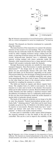
Fig. 14 Schematic representation of several head moieties: a) fluorescent chemosensor, 75 b) C60-based heads, 27 c) ligands containing suitable binding<br />
sites in a correct arrangement <strong>for</strong> metal ion complexation, 28 d) head moieties functionalised with reactive sites. 32<br />
channel. The channels are there<strong>for</strong>e terminated in a generally<br />
plug like manner.<br />
The main function of the stopcocks is to connect the <strong>antenna</strong><br />
function of the crystal to its surroundings. They act as bridges<br />
between the dye molecules inside the channels and the outside<br />
world by either trapping excitation energy coming from the<br />
inside, or injecting excitation energy into the dye-loaded zeolite<br />
crystal. Stopcock-traps there<strong>for</strong>e have a sufficiently large<br />
spectral overlap integral with donor molecules inside the<br />
channels, while stopcock-donors have a large spectral overlap<br />
integral with acceptor molecules inside the channels.<br />
Strongly fluorescent molecules are suitable <strong>for</strong> these energy<br />
transport functions. Since fluorescence is usually quenched by<br />
dimerisation 25,26 the design must be such that the chromophores<br />
do not electronically interact with each other. Both<br />
heads and labels can be fluorescent, depending on the needs.<br />
Fluorescent labels have the advantage of being protected by the<br />
zeolite framework. They are stabilised chemically and cannot<br />
<strong>for</strong>m quenching dimers due to lack of space. Fluorescent heads<br />
on the other hand are closer to the external surface which is<br />
desirable <strong>for</strong> coupling the <strong>antenna</strong> to a device.<br />
The labels are based on organic and silicon–organic backbones.<br />
The simplest <strong>for</strong>m of a label is non-reactive. Its only<br />
function is to enter and to hook to the channel. Non-reactive<br />
labels can be either neutral or cationic. Reactive labels enter the<br />
zeolite channels and then undergo a chemical reaction under<br />
the influence of irradiation, heat or a sufficiently small reactant.<br />
In this way they hook themselves inside the zeolite channels or<br />
maybe bind to molecules already present.<br />
The heads of the stopcock molecules are too large to be able<br />
to enter the channels. Typical functionalised groups such as<br />
bucky balls, 27 chelating centres 28 and others can be used. Some<br />
examples are given in Fig. 14. Smilarly to the labels, heads can<br />
be reactive or non-reactive. Reactive heads may have ‘‘arms’’<br />
which can interact with each other to <strong>for</strong>m a ‘‘monolayer<br />
polymer’’ or bind to the zeolite external surface.<br />
In some cases it is desirable to add a spacer which elongates<br />
the stopcock molecule so that the length of the tail can be<br />
controlled. This can be a tool to improve the solubility of the<br />
whole molecule. Polar groups might help to bind the molecules<br />
more strongly inside the zeolite channels. Spacers which are<br />
sufficiently flexible so that they can bend the tail into the zeolite<br />
channels include e.g. aliphatic chains, polyethers or amides.<br />
Positively charged stopcocks can be plugged in the zeolite<br />
channels by ion exchange while neutral stopcocks can be added<br />
by dehydration of the zeolite channels and adsorption from a<br />
non-aqueous solution or from the gas phase. The zeolite’s<br />
external surface consists of a cylinder coat and two edges.<br />
These two surfaces differ in a number of properties so that the<br />
interactions can be tuned. For MFI type zeolites, as an<br />
example, it was reported that guest molecules bind to the holes<br />
on the external surface much more strongly than on the<br />
framework between the holes. 29<br />
The specific coupling of the photonic <strong>antenna</strong> via the<br />
stopcocks to a target depends on the functionality envisaged.<br />
Direct linkage to a semiconductor surface, embedding into a<br />
semiconducting polymer, organisation of crystals bearing ionic<br />
stopcocks by means of charged polymers, 30,31 or linkage to sites<br />
of biological interest are possibilities.<br />
4.2 Mono-directional <strong>antenna</strong> materials<br />
In mono-directional <strong>antenna</strong> <strong>system</strong>s the energy is transported<br />
in one direction only. We discuss the possibilities sketched in<br />
Fig. 15 to create asymmetrical <strong>antenna</strong> materials. Either the<br />
insertion of the dyes into the zeolite channels is controlled such<br />
that the molecules can penetrate the channels only from one<br />
side, or crystals containing different dyes are organised<br />
appropriately.<br />
Asymmetric loading of zeolite L crystals is possible if the<br />
channel openings are selectively closed on one side so that the<br />
dyes can be inserted from the other side in sequence by the same<br />
procedure as used <strong>for</strong> the preparation of the bi-directional<br />
<strong>antenna</strong> materials. 4 Organising the crystals on a substrate,<br />
maybe by linking them covalently, 32 in order to inhibit the<br />
penetration of dye molecules from the substrate side, is a way<br />
to realise this. Microstructured substrates have been used to<br />
organise relatively large zeolite ZSM-5 crystals in a plane. 33<br />
Other <strong>for</strong>ces which have been used <strong>for</strong> this purpose are<br />
Fig. 15 Schematic view of three strategies <strong>for</strong> the preparation of mono-directional <strong>antenna</strong> materials. a) Organisation of zeolite L crystals on a<br />
substrate. The channels are oriented perpendicular to the surface. Dye molecules can only be inserted from one side. b) Multilayer organisation of<br />
charged polymers and zeolite L crystals loaded with different dyes. c) Multilayer organisation of oppositely charged zeolite L crystals.<br />
8 J. Mater. Chem., 2002, 12, 1–13