Photonic antenna system for light harvesting
Photonic antenna system for light harvesting
Photonic antenna system for light harvesting

Create successful ePaper yourself
Turn your PDF publications into a flip-book with our unique Google optimized e-Paper software.
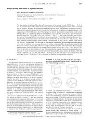
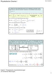
Fig. 10 Refraction and pathway of the emission from the object O<br />
hitting the zeolite L/air interface. a) Emission at O which hits the wall at<br />
an angle between 17 and 42u can be detected by the microscope. Its<br />
refraction makes it appear to originate from the region O’, i.e. closer to<br />
the wall. b) Emission at O which hits the wall at an angle greater than<br />
42u is totally reflected and can travel around the crystal until it reaches<br />
one of the two ends.<br />
the luminescent ring with a dark spot in the middle. Emission at<br />
O which hits the wall at an angle between 17 and 42u, as shown<br />
in Fig. 10a), is refracted but can still be detected by the<br />
microscope. It appears to originate further away from the<br />
centre than it is in reality. As a consequence, the centre appears<br />
darker. Total reflection, as shown in Fig. 10b), causes a photon<br />
to travel on a helical pathway until it reaches the top or the<br />
bottom of the cylinder. If the photon encounters another<br />
excited molecule on its way, stimulated emission can occur. The<br />
in<strong>for</strong>mation from where the emission originates is nearly totally<br />
lost. An angle of total reflection can only be realised by excited<br />
molecules which are near the side walls. This again makes the<br />
centre appear darker. The phenomenon seems to reveal the<br />
characteristics of a very tiny ring resonator which, however,<br />
perhaps resembles the ring resonator reported recently <strong>for</strong><br />
much larger crystals. 19<br />
3.2 Polarisation of the fluorescence<br />
Dye molecules of interest <strong>for</strong> energy transport in our <strong>system</strong>,<br />
have an oblong <strong>for</strong>m and a strong p–p*-transition with a<br />
transition moment parallel to the molecules’ long axis. The<br />
absorption and emission of <strong>light</strong> from these molecules is<br />
there<strong>for</strong>e strongly polarised. In an ensemble of many molecules<br />
this polarisation can only be observed when the molecules are<br />
ordered. Their width allows them to penetrate the onedimensional<br />
channels of zeolite L. The geometrical constraints<br />
lead to an anisotropic organisation of the dyes and result in a<br />
net polarisation anisotropy.<br />
How exactly the molecules are oriented inside the channels<br />
depends on their specific shape and on the adsorption<br />
interaction between the dyes and the channel walls or charge<br />
compensating cations. Because of the dye’s oblongness a<br />
double-cone like distribution in the channels is a reasonable<br />
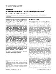
model. This distribution is illustrated in Fig. 11a). The arrows<br />
represent the transition moments of the dyes and a describes<br />
the half opening angle of the double cone. The hexagonal<br />
structure of the zeolite L crystal hence allows six equivalent<br />
positions of the transition moments on this double cone with<br />
respect to the channel axis.<br />
Fig. 11b) shows how the fluorescence polarisation of a single<br />
zeolite L crystal can be analysed by means of a polariser, which<br />
only transmits the indicated polarisation direction. In Fig. 11c)<br />
the theoretical relative intensity of the observed fluorescence is<br />
plotted versus the angle e between the observed polarisation<br />
and the crystal c-axis <strong>for</strong> different values of a.Ifa is equal to 0u,<br />
the molecules’ transition moment coincides with the crystal<br />
c-axis and maximum fluorescence can be observed at e equal to<br />
0 or 180u. Such a crystal emits most of its fluorescence parallel<br />
to the crystal axis and remains dark if the polariser is set<br />
perpendicular to it. If a is equal to 90u, then the maximum<br />
fluorescence is observed perpendicular to the c-axis and the<br />
crystal emits no <strong>light</strong> parallel to it. For all a values between 0<br />
and 90u there is a gradual change in behaviour leads from one<br />
extreme to the other. The differences between the maximum<br />
and minimum fluorescence intensity is reduced and at a magic<br />
angle of 54.7u no fluorescence anisotropy can be observed<br />
although the transition moments are not randomly oriented in<br />
the crystal.<br />
In the case of Ox z in zeolite L a half cone angle a of 72u was<br />
obtained from quantitative measurements on single crystals. 15<br />
The orientation of the transition moments with respect to the<br />
zeolite channels can be determined directly from the fluorescence<br />
polarisation whereas the orientation of the transition<br />
moments with respect to the molecular axis can not be<br />
determined from these experiments. Strong electric fields can<br />
change the orientation of the dipole moments; i.e. the Stark<br />
effect. 20 Geometrical estimates of the maximum angle of the<br />
double cone in the case of Ox z led to the conclusion that the<br />
angle a <strong>for</strong> the molecules can not be larger than 40u. The<br />
observation of a~72u <strong>for</strong> the transition moments was<br />
interpreted by the existence of a remarkable Stark effect in<br />
these materials. 15 The arguments do not apply <strong>for</strong> molecules<br />
aligned along the channel axis.<br />
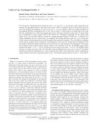
In Fig. 12 fluorescence microscopy images of different dyeloaded<br />
zeolite L single crystals are shown. Each line consists of<br />
three images of the same sample, but with different polarisation<br />
of the fluorescence observed. In the first one the total<br />
fluorescence of the crystals is shown and in the others the<br />
fluorescence with the polarisation direction indicated by the<br />
arrows is displayed. The zeolite was loaded with the following<br />
dyes: A Py z , B PyGY z , C PyB z , D POPOP (see Table 1).<br />
Most crystals show a typical sandwich structure with<br />
fluorescent dyes at the crystal ends and a dark zone in the<br />
middle. This situation can be observed when the diffusion of<br />
the dyes in the channels has not yet reached its equilibrium<br />
situation. It illustrates nicely how the molecules penetrate the<br />
crystals via the two openings on each side of the onedimensional<br />
channels.<br />
Fig. 11 a) Distribution of the transition moments on a double cone with a half opening angle a. b) Polarisation direction observed when a single<br />
crystal is examined by means of a polariser. c) Relative intensity of the observed fluorescence as a function of the observation angle e with respect to<br />
the crystal c-axis, <strong>for</strong> different half cone angles a.<br />
6 J. Mater. Chem., 2002, 12, 1–13