Photonic antenna system for light harvesting
Photonic antenna system for light harvesting
Photonic antenna system for light harvesting

You also want an ePaper? Increase the reach of your titles
YUMPU automatically turns print PDFs into web optimized ePapers that Google loves.
<strong>Photonic</strong> <strong>antenna</strong> <strong>system</strong> <strong>for</strong> <strong>light</strong> <strong>harvesting</strong>, transport and trapping<br />
Gion Calzaferri,* a Marc Pauchard, a Huub Maas, a Stefan Huber, a Abderrahim Khatyr a and<br />
Tjeerd Schaafsma b<br />
a Department of Chemistry and Biochemistry, University of Berne, Freiestr. 3, 3012 Berne,<br />
Switzerland. E-mail: gion.calzaferri@iac.unibe.ch<br />
b Laboratory of Biophysics, Department of Agrotechnology and Food Sciences, Wageningen<br />
University, Dreijenlaan 3, 6703 HA Wageningen, The Netherlands<br />
Received 11th July 2001, Accepted 7th August 2001<br />
First published as an Advance Article on the web 20th September 2001<br />
Host–guest composites with photonic <strong>antenna</strong> properties<br />
are described. The material consists of cylindrical zeolite<br />
L crystals the channels of which are filled with chains of<br />
joined but electronically non-interacting dye molecules.<br />
Light shining on a crystal is first absorbed and the<br />
energy is then transported by the dye molecules inside<br />
the tubes to the desired part. Data on crystals in the size<br />
range of 30 nm up to 3000 nm are reported. The synthesis<br />
principle we are using is based on the fact that<br />
molecules can diffuse into individual channels. This<br />
means that given the appropriate conditions, they can<br />
also leave the zeolite by the same way. In some cases,<br />
however, it is desirable to block their way out, <strong>for</strong> stability<br />
reasons. This is done by adding a closure molecule.<br />
The general approach to connect the <strong>antenna</strong> function to<br />
its surroundings is to add ‘‘stopcock’’ molecules which<br />
generally consist of a head, a spacer and a label. They<br />
can either trap excitation energy on the external surface<br />
or inject excitation energy into the dye-loaded crystal.<br />
The stopcock molecules act as bridges between the dye<br />
molecules inside the channels and the outside world.<br />
Functionalisation of the closure and the stopcock molecules<br />
is an option <strong>for</strong> tuning e.g. wettability, refractive<br />
index, and chemical reactivity. The wide-ranging tunability<br />
of the dye–zeolite L composites makes them useful <strong>for</strong><br />
many applications. We discuss demonstration experiments<br />
which show the process of energy transfer and energy<br />
migration as educational tools, applications as high quality<br />
and non-toxic pigments, use as strongly luminescent<br />
pigments applicable as colour-changing media <strong>for</strong> LEDs,<br />
options <strong>for</strong> realising nanoscaled laser materials, and finally<br />
the challenge <strong>for</strong> realising solid state solar cells based<br />
on sensitisation of a thin semiconductor layer by energy<br />
transfer, the reversal of which can also lead to a new<br />
generation of LEDs.<br />
1. Introduction<br />
A photonic <strong>antenna</strong> is an organised multi-component arrangement<br />
in which several chromophores absorb the incident <strong>light</strong><br />
and channel the excitation energy to a common acceptor<br />
component. Imaginative attempts to build an artificial <strong>antenna</strong><br />
different from ours have been presented in the literature.<br />
Multinuclear luminescent metal complexes, multichromophore<br />
cyclodextrins, Langmuir–Blodgett films, dyes in polymer<br />
matrices and dendrimers have been investigated. Sensitisation<br />
processes in silver halide photographic materials and also the<br />
spectral sensitisation of polycrystalline titanium dioxide films<br />
in some cases show aspects of artificial <strong>antenna</strong> <strong>system</strong>s (<strong>for</strong><br />
references see ref. 1). The materials which have been reported<br />
by us so far are of a bi-directional type. They are based on<br />
JOURNAL OF<br />
Feature Article<br />
Materials<br />
CHEMISTRY<br />
zeolite L as a host, and able to collect and transport excitation<br />
energy. 1–5 The transport is enabled by specifically organised<br />
dye molecules which mimic the natural function of chlorophyll.<br />
The zeolite L crystals consist of a continuous one-dimensional<br />
tube <strong>system</strong>. We have filled each tube with chains of joined but<br />
electronically non-interacting dye molecules. Light shining on<br />
the cylinder is first absorbed and the energy is then transported<br />
by the dye molecules inside the tubes to a desired region.<br />
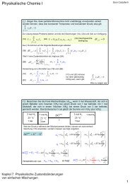
The principle of two types of photonic <strong>antenna</strong> materials is<br />
illustrated in Fig. 1. The rectangles represent sites <strong>for</strong> dye<br />
molecules. Light gray rectangles are sites which contain donors<br />
while the dark rectangles contain acceptors. Both donors and<br />
acceptors are assumed to be strongly luminescent dyes. The dye<br />
molecule in Fig. 1a) which has been excited by absorbing an<br />
incident photon, transfers its electronic excitation to a neighbouring<br />
dye molecule. After a series of energy migration steps<br />
the electronic excitation reaches an acceptor. Energy migration<br />
is in competition with spontaneous emission, radiationless<br />
decay, and photochemically induced degradation. Very fast<br />
energy migration is there<strong>for</strong>e crucial if an acceptor should be<br />
reached be<strong>for</strong>e other processes take place. The energy quantum<br />
can be guided to a reaction centre once it has been captured by<br />
the acceptor. These conditions impose not only spectroscopic<br />
but also decisive geometrical constraints on the <strong>system</strong>.<br />
Recently we have been able to reverse the scheme in Fig. 1a)<br />
having acceptor dyes in the centre, and the donors at both ends,<br />
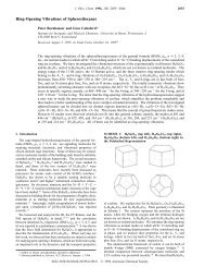
Fig. 1 Representation of a cylindrical nanocrystal consisting of organised<br />
dye molecules acting as donors (<strong>light</strong> grey rectangles) and<br />
acceptors (dark grey rectangles). a) The donors are in the middle part of<br />
the crystal and the acceptors at the front and the back of each channel.<br />
b) The donors are at the front and the back of each channel and the<br />
acceptors are in the middle part. The enlargements show details of a<br />
channel with a dye and its electronic transition moment (arrow) which<br />
is parallel with respect to the channel axis <strong>for</strong> long molecules and bent<br />
<strong>for</strong> shorter ones. The diameter of the channel windows is 0.71 nm and<br />
the largest free diameter is 1.26 nm. The centre to centre distance<br />
between two channels is 1.84 nm.<br />
DOI: 10.1039/b106141k J. Mater. Chem., 2002, 12, 1–13<br />
This journal is # The Royal Society of Chemistry 2002<br />
1
Fig. 2 a) Side and top views of zeolite L crystals with a length of<br />
950 nm and a diameter of 850 nm, respectively. b) A schematic view of<br />
some channels in a hexagonal zeolite crystal with cylindrical morphology.<br />
This is a pre-publication version of figures to be included in a<br />
<strong>for</strong>thcoming work tentatively titled Advances in Photochemistry<br />
Volume 27 edited by D.C. Neckers, to be published in 2002. Copyright<br />
# 2001 John Wiley & Sons Inc. All rights reserved.<br />
as illustrated in Fig. 1b). The material was investigated by<br />
stationary energy migration experiments on an ensemble and<br />
space and time resolved measurements on single crystals. 6<br />
The general synthesis concept of this inorganic–organic<br />
composites is based on the specific geometrical constraints<br />
imposed by the parallel arrangement of one-dimensional<br />
channels of the host. 4,5 Various synthesis strategies <strong>for</strong> the<br />
preparation of chromophores in porous silica and minerals<br />
have been reviewed recently. 7 Zeolite L crystals usually have<br />
cylindrical morphology, as illustrated in Fig. 2, where we also<br />
show a schematic view of their channel structure. The number<br />
of parallel channels which coincide with the c-axis of the hexagonal<br />
framework is equal to 1.07rcyl 2 , where rcyl is the radius of<br />
the crystal in nm. The length of a unit cell along the c-axis is<br />
0.75 nm. This means that a crystal of e.g. 600 nm diameter and<br />
300 nm length gives rise to about 100000 parallel channels, each<br />
consisting of 400 unit cells (u.c.). 8–11<br />
Control of the shape and size of the crystals is a necessary<br />
prerequisite <strong>for</strong> particular applications. Large crystals of a few<br />
hundred to a few thousand nm are very useful <strong>for</strong> studying the<br />
optical and photophysical properties of dye–zeolite composites<br />
on single crystals by means of optical microscopy methods.<br />
Crystals in the range of a few tenths to a few hundred nm are<br />
needed <strong>for</strong> high efficiency photonic <strong>antenna</strong> materials, useful as<br />
fluorescent microprobes in cell biology and analytical chemistry,<br />
12 <strong>for</strong> developing a new generation of dye sensitised solid<br />
state solar cells, 13 or <strong>for</strong> preparing a new generation of <strong>light</strong><br />
emitting diodes. We have recently shown how fine tuning of the<br />
size of zeolite L crystals in the size range of 30 nm up to<br />
3000 nm can be realised by changing the composition of the<br />
starting gel <strong>for</strong> otherwise constant reaction conditions. It was<br />
thus possible to extend the investigations on energy migration<br />
in Py z -loaded zeolite L crystals, modified with Ox z as a<br />
luminescent acceptor at the ends of the crystals; see Table 1 <strong>for</strong><br />
the structuresd of these molecules. 1,5<br />
Some dye molecules which have been inserted into zeolite L<br />
are given in Table 1 where we also give abbreviations used in<br />
this article. It is important to distinguish between three types of<br />
dye molecules. (i) Molecules small enough to fit into a single unit<br />
cell. Some examples are biphenyl (BP), hydoxy-TEMPO,<br />
fluorenone, and naphthalene. (ii) Molecules the size of which<br />
makes it hard to guess if they align along the c-axis or if they find<br />
a way to fit into a single unit cell. Ox z ,Py z , and Th z are<br />
molecules of this type. 15 (iii) Molecules which are so large that<br />
they have no other choice but to align along the c-axis. Many<br />
2 J. Mater. Chem., 2002, 12, 1–13<br />
examples fit into this category. POPOP, DMPOPOP, MBOXE,<br />
pTP, and DPH are among these. It is important to know more<br />
precisely which of the type (ii) and (iii) molecules can arrange in<br />
a way so that they can interact via their p-<strong>system</strong>s and which<br />
are only in physical contact, i.e. have negligible electronic<br />
interaction.<br />
2. Energy migration<br />
The two cationic dyes Py z , as a donor, and Ox z , as an<br />
acceptor, were found to be very versatile to demonstrate<br />
photonic <strong>antenna</strong> functionalities <strong>for</strong> <strong>light</strong> <strong>harvesting</strong>, transport,<br />
and capturing, as illustrated in Fig. 3. They can be incorporated<br />
into zeolite L by means of ion exchange, where they are<br />
present as monomers because of the restricted space. In this<br />
<strong>for</strong>m they have a high fluorescence quantum yield and<br />
favourable spectral properties. The insertion of the dyes can<br />
be visualised by means of fluorescence microscopy. The<br />
fluorescence anisotropy of Ox z -loaded zeolite L has recently<br />
been investigated in detail by conventional and by confocal<br />
microscopy techniques. 15<br />
The occupational probability p of the sites with a dye is equal<br />
to the number of occupied sites divided by the number of sites<br />
available. Using this notion the Förster type energy transfer<br />
16,17 and the energy migration rate constant k ij from a<br />
molecule i to a molecule j in this material can be expressed by: 2<br />
9( ln 10)<br />
128p5NAn4 Wi<br />
kij~ GijJijpipj<br />
(1)<br />
ti<br />
where Wi and ti [s 21 ] are the fluorescence quantum yield and the<br />
intrinsic fluorescence lifetime of the donor, NA is the Avogadro<br />
number, n is the refractive index of the medium, Gij [A˚ 26 ]<br />
represents the geometrical constraints of the sites in the crystal<br />
and the relative orientation of the electronic transition moments,<br />
pi and pj are the occupational probabilities of the sites with<br />
excited donors i and acceptors j in the ground state, and Jij<br />
[cm 3 M 21 ] is the spectral overlap integral between the normalised<br />
donor emission and the acceptor absorption spectrum.<br />
We describe properties of Py z -loaded zeolite L of which the<br />
channel ends are modified with Ox z .Ox z acts as an acceptor<br />
which becomes excited via radiationless energy transfer from an<br />
excited Py z moiety. If radiationless relaxation is not considered,<br />
Ox z can lose its excitation energy only by luminescence,<br />
as it cannot transfer the energy back to Py z because of<br />
its lower value. Fluorescence of excited Py z , internal conversion,<br />
and inter<strong>system</strong> crossing compete with the energy migration<br />
and energy transfer processes. The efficiency of energy<br />
migration among the Py z molecules along the crystal can be<br />
investigated by measuring the front–back trapping efficiency<br />
TFB,‘. The front–back trapping efficiency is equal to the ratio<br />
of fluorescence intensity emitted by the acceptor Ox z (IA) divided by the total fluorescence intensity (IAzID). 2,18<br />
TFB,?~ IA<br />
IDzIA<br />
Two important parameters we can vary independently in order<br />
to test the energy migration efficiency are the loading with<br />
donor molecules Py z , which we express as ppy, and the length<br />
lcyl of the crystals. The front–back trapping efficiency TFB,‘ can<br />
be tested by exciting the crystals at a wavelength where the<br />
acceptor absorption is negligible. We expect that TFB,‘<br />
decreases with increasing crystal length lcyl <strong>for</strong> otherwise<br />
constant parameters, specifically constant ppy, because the<br />
excitation energy has to migrate over an increasingly large<br />
distance to reach an acceptor. This can be tested by using<br />
materials with different average crystal lengths.<br />
We show in Fig. 4 experimental results obtained with crystals<br />
of the following average lengths: A, 300 nm; B, 500 nm; C,<br />
850 nm; D, 1400 nm; and E, 2400 nm. These crystals were<br />
(2)
Table 1 Dye molecules and abbreviations<br />
BP Py z<br />
pTP PyGY z<br />
DPH PyB z<br />
PBOX Ox z<br />
MBOXE Th z<br />
POPOP ResH<br />
DMPOPOP Hydroxy-TEMPO<br />
DSC DMSI z<br />
Fluorenone N-Ethylcarbazole<br />
Naphthalene a<br />
a From ref. 14.<br />
loaded with Py z in such a way that the occupational<br />
probability was always the same, namely p py~0.11. They<br />
were then modified with two Ox z molecules on average at both<br />
ends of each channel. The fluorescence of a thin layer on quartz<br />
was measured at room temperature after specific excitation of<br />
Py z at 460 nm. It shows a strong increase of the Ox z emission<br />
with decreasing crystal length lcyl. The front–back trapping<br />
efficiency increases from 0.33 up to 0.91. This means that in the<br />
300 nm crystals, 91% of the emitted <strong>light</strong> is due to energy<br />
migration among the Py z molecules and finally transfer to the<br />
luminescent acceptor Ox z . Experiments with crystals in the<br />
size range of 50 nm show a similar behaviour.<br />
A small shift of the Py z maximum, from 525 nm <strong>for</strong> the<br />
smallest crystals to 530 nm <strong>for</strong> the largest ones, is observed.<br />
Anthracene a<br />
This wavelength shift may be due to self-absorption and reemission<br />
because the absorption depth increases with increasing<br />
crystal size despite the constant ppy. The maximum of the<br />
Ox z emission remains at 605 nm.<br />
The time evolution of the excitation distribution along the<br />
cylinder axis of this material is of great interest. 1,2,6 We report<br />
theoretical results obtained <strong>for</strong> a crystal consisting of 90 slabs,<br />
each of which corresponds to the thickness of a site. The<br />
photophysical data of Py z as donor and Ox z as acceptor were<br />
used to calculate the excitation distribution of the donors.<br />
Immediately after excitation all slabs have the same excitation<br />
probability. The excitation distribution is shown after 5, 10, 50<br />
and 100 ps. We observe in Fig. 5a) that the slabs close to the<br />
acceptor layers lose their excitation energy very quickly. The<br />
J. Mater. Chem., 2002, 12, 1–13 3
Fig. 3 Simplified view of a bi-directional photonic <strong>antenna</strong>. The middle<br />
part shown in <strong>light</strong> grey contains donor molecules D. After excitation<br />
of D to D* the excitation energy migrates with equal probability to the<br />
left and to the right until it reaches an acceptor A (dark grey) which<br />
captures the excitation energy and emits it as red-shifted <strong>light</strong>.<br />
Fig. 4 a) EM pictures of the investigated zeolite L samples with<br />
different mean crystal lengths l cyl: A, 300 nm; B, 500 nm; C, 850 nm; D,<br />
1400 nm; E, 2400 nm (the bars in A–D correspond to 1 mm, in E to<br />
3 mm). b) Fluorescence intensity (scaled to the same height at the<br />
maximum of the Py z emission) of Py z -loaded and Ox z modified<br />
zeolite L crystals with constant Py z loading (ppy~0.11) as a function of<br />
crystal length after specific excitation of only Py z at 460 nm. The Ox z<br />
modification was, on average, two molecules at both ends of each<br />
channel. 5<br />
trapping rate is proportional to the gradient of the excitation<br />
distribution at the position of the acceptors. Hence, it depends<br />
not only on the remaining excitation probability but also on<br />
the excitation distribution. This is in contrast to the donor<br />
fluorescence rate, which depends only on the excitation distribution<br />
of the donors. The fluorescence rate of the acceptors<br />
is proportional to their excitation probability. We there<strong>for</strong>e<br />
expect a fluorescence decay behaviour as illustrated in Fig. 5b).<br />
The fluorescence decay of the donors becomes much faster<br />
in the presence of acceptors, because of the depopulation<br />
due to the irreversible energy transfer to the acceptors. The<br />
Fig. 6 a) Principle of a bi-directional three-dye photonic <strong>antenna</strong>. The<br />
enlarged section shows the organisation of individual dye molecules at<br />
the domain boundary between dye2 and dye3. b) Fluorescence<br />
microscopy images of an Ox z ,Py z ,POPOP–zeolite L crystal of<br />
2000 nm length upon selective excitation of A POPOP at 330–<br />
385 nm, B Py z at 470–490 nm, and C Ox z at 545–580 nm. The<br />
excitation <strong>light</strong> was eliminated by appropriate cut-off filters in front of<br />
the CCD-camera: A 410 nm, B 515 nm, C 605 nm.<br />
fluorescence intensity stemming from the acceptors initially<br />
increases because excited states must first be populated via<br />
energy transfer from the donors. It there<strong>for</strong>e reaches a maximum<br />
be<strong>for</strong>e it decays.<br />
A sophisticated bi-directional <strong>antenna</strong> material with three<br />
dyes is illustrated in Fig. 6. 4 After selective excitation of dye1,<br />
located in the middle part, the <strong>light</strong> energy is carried spectrally<br />
from the blue to green (dye2) to red (dye3) and spatially from<br />
the crystal centre to its left and right ends. The stacking of the<br />
dyes in the crystal can be seen in microscopy images taken on<br />
relatively large crystals (Fig. 6b)). We show this <strong>for</strong> a 2000 nm<br />
crystal with POPOP in the middle, followed by Py z and then<br />
by Ox z . The different colour regions which can be observed in<br />
this experiment are impressive. Image A shows the fluorescence<br />
observed after selective excitation of the POPOP. The middle of<br />
the crystal shows the blue fluorescence of POPOP while the red<br />
emission of Ox z appears at both ends. Between these two<br />
zones the superposition of the fluorescence of all three dyes<br />
results in emission of white <strong>light</strong>. In image B the fluorescence is<br />
shown after selective excitation of the Py z . The red emission,<br />
hardly visible at both ends, and the green emission stem from<br />
the Ox z and the Py z , respectively. The yellow emission is due<br />
to superposition of the green and red fluorescence. Image C<br />
shows the emission of Ox z after selective excitation of only<br />
Fig. 5 a) Excitation distribution along the channel axis of a zeolite L crystal consisting of 90 slabs (occupational probability p~0.3) under the<br />
condition of equal excitation probability at t~0 calculated <strong>for</strong> front–back trapping. Fluorescence of the donors is taken into account. A: t~5 ps, B:<br />
t~10 ps, C: t~50 ps, and D: t~100 ps after irradiation. b) Fluorescence decay of the donors in the absence of acceptors (dotted), in the presence of<br />
acceptors at both ends (solid), and fluorescence decay of the acceptors (dashed).<br />
4 J. Mater. Chem., 2002, 12, 1–13
Ox z . These three microscopy images show very nicely the<br />
sequence of the inserted dyes in the channels, although the<br />
limited resolution does not allow one to observe completely<br />
separated regions. The microscopy pictures show how the<br />
resolution of the microscope decreases with longer wavelength<br />
of the observed <strong>light</strong>. Although the concentration of Ox z in the<br />
crystal is much lower than that of POPOP with the Ox z<br />
molecules located only at the very ends of the channels, the<br />
observed fluorescence in image C appears over a large area of<br />
the crystal.<br />
After this overview of photonic <strong>antenna</strong> properties we now<br />
turn to some intriguing optical properties we have recently<br />
observed in different dye–zeolite guest–host composites.<br />
3. Optical properties<br />
We describe observations made on dye-loaded zeolite L crystals<br />
of dimensions which are at least equal to or a few times larger<br />
than the wavelength of visible <strong>light</strong>. The refractive index of<br />
zeolites is in the same range as that of quartz. It is expected to<br />
vary to some extent depending on the cations, the water<br />
content, and the dye loading. Thus optical effects observed in<br />
tiny glass fibres are expected to appear in zeolite L crystals as<br />
well. The luminescent dyes inserted into the channels cause<br />
some new phenomena, also because of the pronounced<br />
anisotropy of their <strong>light</strong> absorption and emission properties<br />
and because the refractive index changes in regions of strong<br />
absorption. The orientation of the electronic transition<br />
moments of Ox z in zeolite L is 72u with respect to the c-axis<br />
while that of POPOP, DMPOPOP and similar molecules is<br />
parallel to this axis. 1,15<br />
3.1 Fata morgana effects in dye-loaded zeolite L crystals<br />
Optical effects due to refraction and total internal reflection<br />
have been observed in dye-loaded zeolite L crystals of 2.5 mm<br />
length and 1.4 mm diameter by means of an optical microscope<br />
equipped with polarisers, narrow band and cutoff filters. An<br />
astonishing effect taking place in an Ox z -loaded crystal is seen<br />
in Fig. 7. Looking at the polarised red emission, a homogeneous<br />
intensity distribution is observed over the whole<br />
crystal, with the exception of two perpendicular dark lines<br />
which separate the luminescence at both ends. The fluorescence<br />
in the middle part of the crystal decreases, when turning the<br />
polariser by 90u, but the two wings at both sides appear with<br />
about the same intensity as be<strong>for</strong>e. Obviously the <strong>light</strong><br />
observed at both ends of the crystal is not polarised while<br />
that observed in the middle part is strongly polarised. Ox z<br />
molecules located at the outer surface of the crystals can be<br />
quantitatively destroyed by treating the material with a<br />
hypochlorite solution. 3,5 Such a treatment does not alter the<br />
optical properties of the material. The effect (dark lines and<br />
wings) disappears, however, upon refractive index matching,<br />
e.g. when applying an immersion oil. This means that the<br />
optical phenomenon is not due to some molecules present at<br />
the outer surface. We have to seek <strong>for</strong> another explanation.<br />
The luminous non-polarised wings are due to part of the<br />
Fig. 7 Polarised fluorescence microscopic pictures of a 2.5 mm long<br />
Ox z -loaded zeolite L crystal after excitation at 545–580 nm (cut-off<br />
605 nm). The arrows indicate the transmission direction of the<br />
polariser.<br />
Fig. 8 Refraction and pathway of the emission from the object O<br />
hitting the zeolite L/air interface. a) Refraction of the emission from the<br />
object O at the zeolite L/air interface observed at an angle a 2. The<br />
emission appears in the range between 0u and the critical angle <strong>for</strong> total<br />
reflection a1,max which is 42u (d is the distance between O and the<br />
interface). b) Pathway of the emission of a molecule O.<br />
emission built up in the middle of the crystal. They can be<br />
understood when taking total internal reflection into account.<br />
Refraction of the emission from the object O at the zeolite L/air<br />
interface observed at an angle a 2 is explained in Fig. 8a). The<br />
emission can appear between 0u and the critical angle <strong>for</strong> total<br />
reflection a 1,max, which is 42u <strong>for</strong> a refractive index of 1.49. The<br />
used objective of the microscope collects all <strong>light</strong> that is emitted<br />
under an angle a2v64u and there<strong>for</strong>e the object appears at the<br />
positions O’ in a circle with radius Dl around the object O.<br />
An incident photon hitting the wall at an angle a1 larger than<br />
42u is totally reflected and can only leave the cylinder at its ends<br />
(see Fig. 8b)). In the case shown on the right side of Fig. 8b), it<br />
appears as luminous non-polarised wings. Hence, the emission<br />
observed in an optical microscope appears not at the origin of<br />
the molecule but outside of the crystal at both ends. This means<br />
that ‘‘we see’’ the emitting molecules at another place in space<br />
than they are, similarly to a mirage, which shows an image<br />
which may be hundreds of kilometres away, but can appear to<br />
be closer than it is. This phenomenon is called fata morgana.<br />
We are not sure if we understand the second part of the<br />
observation, namely the two dark regions which separate the<br />
polarised emission of the bulk from the non-polarised wings,<br />
but these may be due to interference phenomena.<br />
Another nice fata morgana can be observed in DMPOPOP–<br />
zeolite L microcrystals, the luminescence of which is strongly<br />
polarised along the c-axis. Looking at standing crystals, a nonpolarised<br />
blue ring with a dark centre is observed, see Fig. 9a).<br />
The dark part disappears immediately, the whole luminescent<br />
spot shrinks, and the luminescence intensity decreases when<br />
adding a drop of a solvent with the same refractive index as the<br />
zeolite. This shows that the blue ring is caused by refraction at<br />
the crystal/air interface.<br />
Two kinds of refraction are responsible <strong>for</strong> the appearance of<br />
Fig. 9 Fluorescence microscopic pictures of a standing 2.5 mm long<br />
DMPOPOP-loaded zeolite L crystal upon excitation at 330–385 nm<br />
and observed with a cut-off filter (410 nm), a) in air and b) in a<br />
refractive index matching solvent.<br />
J. Mater. Chem., 2002, 12, 1–13 5
Fig. 10 Refraction and pathway of the emission from the object O<br />
hitting the zeolite L/air interface. a) Emission at O which hits the wall at<br />
an angle between 17 and 42u can be detected by the microscope. Its<br />
refraction makes it appear to originate from the region O’, i.e. closer to<br />
the wall. b) Emission at O which hits the wall at an angle greater than<br />
42u is totally reflected and can travel around the crystal until it reaches<br />
one of the two ends.<br />
the luminescent ring with a dark spot in the middle. Emission at<br />
O which hits the wall at an angle between 17 and 42u, as shown<br />
in Fig. 10a), is refracted but can still be detected by the<br />
microscope. It appears to originate further away from the<br />
centre than it is in reality. As a consequence, the centre appears<br />
darker. Total reflection, as shown in Fig. 10b), causes a photon<br />
to travel on a helical pathway until it reaches the top or the<br />
bottom of the cylinder. If the photon encounters another<br />
excited molecule on its way, stimulated emission can occur. The<br />
in<strong>for</strong>mation from where the emission originates is nearly totally<br />
lost. An angle of total reflection can only be realised by excited<br />
molecules which are near the side walls. This again makes the<br />
centre appear darker. The phenomenon seems to reveal the<br />
characteristics of a very tiny ring resonator which, however,<br />
perhaps resembles the ring resonator reported recently <strong>for</strong><br />
much larger crystals. 19<br />
3.2 Polarisation of the fluorescence<br />
Dye molecules of interest <strong>for</strong> energy transport in our <strong>system</strong>,<br />
have an oblong <strong>for</strong>m and a strong p–p*-transition with a<br />
transition moment parallel to the molecules’ long axis. The<br />
absorption and emission of <strong>light</strong> from these molecules is<br />
there<strong>for</strong>e strongly polarised. In an ensemble of many molecules<br />
this polarisation can only be observed when the molecules are<br />
ordered. Their width allows them to penetrate the onedimensional<br />
channels of zeolite L. The geometrical constraints<br />
lead to an anisotropic organisation of the dyes and result in a<br />
net polarisation anisotropy.<br />
How exactly the molecules are oriented inside the channels<br />
depends on their specific shape and on the adsorption<br />
interaction between the dyes and the channel walls or charge<br />
compensating cations. Because of the dye’s oblongness a<br />
double-cone like distribution in the channels is a reasonable<br />
model. This distribution is illustrated in Fig. 11a). The arrows<br />
represent the transition moments of the dyes and a describes<br />
the half opening angle of the double cone. The hexagonal<br />
structure of the zeolite L crystal hence allows six equivalent<br />
positions of the transition moments on this double cone with<br />
respect to the channel axis.<br />
Fig. 11b) shows how the fluorescence polarisation of a single<br />
zeolite L crystal can be analysed by means of a polariser, which<br />
only transmits the indicated polarisation direction. In Fig. 11c)<br />
the theoretical relative intensity of the observed fluorescence is<br />
plotted versus the angle e between the observed polarisation<br />
and the crystal c-axis <strong>for</strong> different values of a.Ifa is equal to 0u,<br />
the molecules’ transition moment coincides with the crystal<br />
c-axis and maximum fluorescence can be observed at e equal to<br />
0 or 180u. Such a crystal emits most of its fluorescence parallel<br />
to the crystal axis and remains dark if the polariser is set<br />
perpendicular to it. If a is equal to 90u, then the maximum<br />
fluorescence is observed perpendicular to the c-axis and the<br />
crystal emits no <strong>light</strong> parallel to it. For all a values between 0<br />
and 90u there is a gradual change in behaviour leads from one<br />
extreme to the other. The differences between the maximum<br />
and minimum fluorescence intensity is reduced and at a magic<br />
angle of 54.7u no fluorescence anisotropy can be observed<br />
although the transition moments are not randomly oriented in<br />
the crystal.<br />
In the case of Ox z in zeolite L a half cone angle a of 72u was<br />
obtained from quantitative measurements on single crystals. 15<br />
The orientation of the transition moments with respect to the<br />
zeolite channels can be determined directly from the fluorescence<br />
polarisation whereas the orientation of the transition<br />
moments with respect to the molecular axis can not be<br />
determined from these experiments. Strong electric fields can<br />
change the orientation of the dipole moments; i.e. the Stark<br />
effect. 20 Geometrical estimates of the maximum angle of the<br />
double cone in the case of Ox z led to the conclusion that the<br />
angle a <strong>for</strong> the molecules can not be larger than 40u. The<br />
observation of a~72u <strong>for</strong> the transition moments was<br />
interpreted by the existence of a remarkable Stark effect in<br />
these materials. 15 The arguments do not apply <strong>for</strong> molecules<br />
aligned along the channel axis.<br />
In Fig. 12 fluorescence microscopy images of different dyeloaded<br />
zeolite L single crystals are shown. Each line consists of<br />
three images of the same sample, but with different polarisation<br />
of the fluorescence observed. In the first one the total<br />
fluorescence of the crystals is shown and in the others the<br />
fluorescence with the polarisation direction indicated by the<br />
arrows is displayed. The zeolite was loaded with the following<br />
dyes: A Py z , B PyGY z , C PyB z , D POPOP (see Table 1).<br />
Most crystals show a typical sandwich structure with<br />
fluorescent dyes at the crystal ends and a dark zone in the<br />
middle. This situation can be observed when the diffusion of<br />
the dyes in the channels has not yet reached its equilibrium<br />
situation. It illustrates nicely how the molecules penetrate the<br />
crystals via the two openings on each side of the onedimensional<br />
channels.<br />
Fig. 11 a) Distribution of the transition moments on a double cone with a half opening angle a. b) Polarisation direction observed when a single<br />
crystal is examined by means of a polariser. c) Relative intensity of the observed fluorescence as a function of the observation angle e with respect to<br />
the crystal c-axis, <strong>for</strong> different half cone angles a.<br />
6 J. Mater. Chem., 2002, 12, 1–13
Fig. 12 Fluorescence microscopy images of dye-loaded zeolite L single<br />
crystals, without polariser (first column) and with polariser (second and<br />
third column: the direction of the transmitted polarisation is indicated<br />
by the arrows). Samples: A Py z –zeolite L, B PyGY z –zeolite L, C<br />
PyB z –zeolite L, D POPOP–zeolite L.<br />
Py z is a molecule with similar dimensions as Ox z and<br />
there<strong>for</strong>e the behaviour of the fluorescence polarisation is the<br />
same as already described <strong>for</strong> the Ox z –zeolite L sample:<br />
maximum fluorescence perpendicular to the crystal axis;<br />
minimum fluorescence parallel to it. PyGY z is s<strong>light</strong>ly larger<br />
than Py z , because of the methyl groups. The observed<br />
fluorescence polarisation in this sample changes significantly<br />
compared to Py z . The maximum fluorescence intensity is now<br />
measured parallel to the c-axis and the difference between<br />
maximum and minimum intensity is rather small. According to<br />
Fig. 11c) this is an indication that the transition moments have<br />
changed to an angle a below 55u. In the case of PyB z (with four<br />
ethyl groups) the intensity difference between the minimum and<br />
maximum intensity is even more pronounced indicating an<br />
angle a near 0u. In the final images of this series the fluorescence<br />
of POPOP–zeolite L crystals is analysed. POPOP has an<br />
estimated molecular length of 19 A˚ and there<strong>for</strong>e occupies<br />
approximately 3 u.c. The fluorescence polarisation in the<br />
images D shows very nicely that the transition moments of the<br />
POPOP molecules are arranged parallel to the c-axis, which<br />
means a is equal to 0u.<br />
4. Further developments<br />
In natural photosynthesis, complex arrays of <strong>antenna</strong>e collect<br />
the solar energy and convert it into chemical potential energy<br />
that drives the chemistry of the photosynthetic machinery. The<br />
processes involved are very fast and highly efficient. 21–23<br />
The dye–zeolite composites reported so far show fascinating<br />
photonic <strong>antenna</strong>e properties which are perhaps comparable<br />
to some extent to those of natural <strong>system</strong>s. Tuning their<br />
chemical and photochemical behaviour, organising in<strong>for</strong>mation<br />
exchange between their inside and the external world, but<br />
also organising individual crystals on a surface in order to<br />
realise e.g. mono-directional functionalities remains a challenge<br />
which we address in this section.<br />
4.1 Closure and stopcock molecules<br />
The synthesis principle we are using is based on the fact that<br />
molecules can diffuse into individual channels. 3,4,24 This means<br />
that under appropriate conditions, they can also leave the<br />
zeolite in the same manner. In some cases, however, it is<br />
desirable to block their way out, so as to stabilise the structure.<br />
This can be done by adding a ’closure’ molecule after the<br />
synthesis has been completed. A variety of closure molecules<br />
which seal the channels completely or only partially can be<br />
used, depending on the requirement. An example already used<br />
is the addition of fluorenone which enters readily but leaves the<br />
structure reluctantly. If more complete sealing is needed<br />
molecules bearing appropriate reactive groups can be used.<br />
Functionalisation of the closure molecules is an option <strong>for</strong><br />
tuning wettability, refractive index, chemical reactivity, and<br />
other properties.<br />
External trapping and injection of quanta is more demanding.<br />
The general approach we are using to solve this problem is<br />
to add ‘‘stopcock’’ molecules as illustrated in Fig. 13. 1 A<br />
stopcock molecule generally consists of three components: a<br />
head, a spacer and a label. The tail moiety (spacerzlabel) has a<br />
longitudinal extension of more than one u.c. along the c-axis.<br />
The head moiety has a lateral extension that is larger than the<br />
channel width and prevents the head from penetrating into the<br />
Fig. 13 a) Typical shape of a stopcock molecule located at the end of a zeolite channel. b) Fluorescent molecules which have already been inserted in<br />
zeolite L are modified with an inert head in order to build stopcock molecules with fluorescent tails. c) Examples of molecules which can be used as<br />
stopcocks with a fluorescent head.<br />
J. Mater. Chem., 2002, 12, 1–13 7
Fig. 14 Schematic representation of several head moieties: a) fluorescent chemosensor, 75 b) C60-based heads, 27 c) ligands containing suitable binding<br />
sites in a correct arrangement <strong>for</strong> metal ion complexation, 28 d) head moieties functionalised with reactive sites. 32<br />
channel. The channels are there<strong>for</strong>e terminated in a generally<br />
plug like manner.<br />
The main function of the stopcocks is to connect the <strong>antenna</strong><br />
function of the crystal to its surroundings. They act as bridges<br />
between the dye molecules inside the channels and the outside<br />
world by either trapping excitation energy coming from the<br />
inside, or injecting excitation energy into the dye-loaded zeolite<br />
crystal. Stopcock-traps there<strong>for</strong>e have a sufficiently large<br />
spectral overlap integral with donor molecules inside the<br />
channels, while stopcock-donors have a large spectral overlap<br />
integral with acceptor molecules inside the channels.<br />
Strongly fluorescent molecules are suitable <strong>for</strong> these energy<br />
transport functions. Since fluorescence is usually quenched by<br />
dimerisation 25,26 the design must be such that the chromophores<br />
do not electronically interact with each other. Both<br />
heads and labels can be fluorescent, depending on the needs.<br />
Fluorescent labels have the advantage of being protected by the<br />
zeolite framework. They are stabilised chemically and cannot<br />
<strong>for</strong>m quenching dimers due to lack of space. Fluorescent heads<br />
on the other hand are closer to the external surface which is<br />
desirable <strong>for</strong> coupling the <strong>antenna</strong> to a device.<br />
The labels are based on organic and silicon–organic backbones.<br />
The simplest <strong>for</strong>m of a label is non-reactive. Its only<br />
function is to enter and to hook to the channel. Non-reactive<br />
labels can be either neutral or cationic. Reactive labels enter the<br />
zeolite channels and then undergo a chemical reaction under<br />
the influence of irradiation, heat or a sufficiently small reactant.<br />
In this way they hook themselves inside the zeolite channels or<br />
maybe bind to molecules already present.<br />
The heads of the stopcock molecules are too large to be able<br />
to enter the channels. Typical functionalised groups such as<br />
bucky balls, 27 chelating centres 28 and others can be used. Some<br />
examples are given in Fig. 14. Smilarly to the labels, heads can<br />
be reactive or non-reactive. Reactive heads may have ‘‘arms’’<br />
which can interact with each other to <strong>for</strong>m a ‘‘monolayer<br />
polymer’’ or bind to the zeolite external surface.<br />
In some cases it is desirable to add a spacer which elongates<br />
the stopcock molecule so that the length of the tail can be<br />
controlled. This can be a tool to improve the solubility of the<br />
whole molecule. Polar groups might help to bind the molecules<br />
more strongly inside the zeolite channels. Spacers which are<br />
sufficiently flexible so that they can bend the tail into the zeolite<br />
channels include e.g. aliphatic chains, polyethers or amides.<br />
Positively charged stopcocks can be plugged in the zeolite<br />
channels by ion exchange while neutral stopcocks can be added<br />
by dehydration of the zeolite channels and adsorption from a<br />
non-aqueous solution or from the gas phase. The zeolite’s<br />
external surface consists of a cylinder coat and two edges.<br />
These two surfaces differ in a number of properties so that the<br />
interactions can be tuned. For MFI type zeolites, as an<br />
example, it was reported that guest molecules bind to the holes<br />
on the external surface much more strongly than on the<br />
framework between the holes. 29<br />
The specific coupling of the photonic <strong>antenna</strong> via the<br />
stopcocks to a target depends on the functionality envisaged.<br />
Direct linkage to a semiconductor surface, embedding into a<br />
semiconducting polymer, organisation of crystals bearing ionic<br />
stopcocks by means of charged polymers, 30,31 or linkage to sites<br />
of biological interest are possibilities.<br />
4.2 Mono-directional <strong>antenna</strong> materials<br />
In mono-directional <strong>antenna</strong> <strong>system</strong>s the energy is transported<br />
in one direction only. We discuss the possibilities sketched in<br />
Fig. 15 to create asymmetrical <strong>antenna</strong> materials. Either the<br />
insertion of the dyes into the zeolite channels is controlled such<br />
that the molecules can penetrate the channels only from one<br />
side, or crystals containing different dyes are organised<br />
appropriately.<br />
Asymmetric loading of zeolite L crystals is possible if the<br />
channel openings are selectively closed on one side so that the<br />
dyes can be inserted from the other side in sequence by the same<br />
procedure as used <strong>for</strong> the preparation of the bi-directional<br />
<strong>antenna</strong> materials. 4 Organising the crystals on a substrate,<br />
maybe by linking them covalently, 32 in order to inhibit the<br />
penetration of dye molecules from the substrate side, is a way<br />
to realise this. Microstructured substrates have been used to<br />
organise relatively large zeolite ZSM-5 crystals in a plane. 33<br />
Other <strong>for</strong>ces which have been used <strong>for</strong> this purpose are<br />
Fig. 15 Schematic view of three strategies <strong>for</strong> the preparation of mono-directional <strong>antenna</strong> materials. a) Organisation of zeolite L crystals on a<br />
substrate. The channels are oriented perpendicular to the surface. Dye molecules can only be inserted from one side. b) Multilayer organisation of<br />
charged polymers and zeolite L crystals loaded with different dyes. c) Multilayer organisation of oppositely charged zeolite L crystals.<br />
8 J. Mater. Chem., 2002, 12, 1–13
adhesion 34 and electric fields. 35 The morphology and the size of<br />
the crystals are important in all cases. ZSM-5 nanoscale seed<br />
crystals have been organised with their largest area surface on<br />
positively charged polymers on a gold surface. Calcination and<br />
growth of the silicalite then led to a densely packed and<br />
oriented polycrystalline layer. 36 Zeolite L crystals can be<br />
organised by modifying them with charged stopcock molecules.<br />
This leads to an anisotropic distribution of the zeolite surface<br />
charges and gives rise to attractive electrostatic interactions<br />
with an oppositely charged substrate. The crystal growth of<br />
AlPO-5 in the presence of floating anodised alumina can be<br />
controlled to obtain vertically aligned hexagonal crystals. 37<br />
To further suppress the insertion of dyes into the channels<br />
from the substrate-side, the channels can be sealed on one<br />
side by adsorption of a polymer onto the substrate. 38<br />
Alternatively, stopcocks can be functionalised specifically<br />
with electro-reactive constituents like ethynylic-, 39 vinylic- 40<br />
or pyrrolic-groups. 41,42 The substrate serves as electrode under<br />
the influence of an electrochemical potential and only the<br />
adjacent heads of the stopcocks react to <strong>for</strong>m a covalently cross<br />
linked structure. The stopcocks are then removed from the<br />
other side of the crystals to unblock the channels <strong>for</strong> the dye<br />
insertion.<br />
The <strong>for</strong>mation of mono-directional <strong>antenna</strong> materials by<br />
organising different dye loaded crystals is illustrated in Fig. 15b)<br />
and c). Assembly of layered organic–inorganic composites is<br />
currently a major research area. 43,44 An increasing number of<br />
articles concerning the assembly of zeolite crystals on<br />
substrates via ionic or covalent bonding, some by the use of<br />
appropriate organic additives, have been published. 45–49 This<br />
knowledge can be used <strong>for</strong> alternate adsorption of charged<br />
polymers and zeolite L crystals modified with stopcocks<br />
bearing a charged head as illustrated in Fig. 15b). Polymeric<br />
materials ranging from biopolymers such as proteins 50,51 to<br />
inorganic macromolecules and clays 52,53 have been assembled<br />
by means of related techniques. Luminescent polymers can be<br />
used as connectors to transport the energy from one crystal to<br />
another one. 54 A simpler concept consists of arranging<br />
differently charged crystals in the manner shown in Fig. 15c).<br />
5. Applications<br />
The tunability in size and properties of the materials described<br />
in the previous sections is so large that we expect them to find<br />
applications in different fields such as optoelectronics,<br />
pigments, molecular probes but also as educational tools. We<br />
focus on five applications amongst these. Some of them are<br />
already feasible, while others require further development.<br />
5.1 Educational tools<br />
There are not many demonstration experiments which show<br />
the process of energy transfer and energy migration well. We<br />
found that the energy transfer between dye molecules inside the<br />
channels of zeolite L works so well that it can be used as a nice<br />
educational tool to show both energy transfer and energy<br />
migration. The reason <strong>for</strong> this is that the dye molecules can be<br />
brought close together without <strong>for</strong>ming dimers. We can vary<br />
the mean distance between the molecules by varying the<br />
occupational probability of the dyes which is directly proportional<br />
to the concentration of the dyes in the zeolite channels.<br />
The volume of a zeolite crystal is given by:<br />
VZ~pr 2 cyl lcyl<br />
where r cyl is the radius of the zeolite crystal and l cyl is the length<br />
of the zeolite crystal. The number of unit cells of one crystal, nuc<br />
is given by:<br />
(3)<br />
nuc~ 2p ffiffi<br />
3<br />
p lcylr 2 cyl<br />
2<br />
jja c<br />
jj 2<br />
where c and a are the primitive vectors of the zeolite L<br />
framework. Now the number of channels in a zeolite crystal<br />
can be written as:<br />
nch~ nucjj c<br />
(5)<br />
lcyl<br />
If ns is the number of unit cells that <strong>for</strong>ms a site and pdye is the<br />
occupational probability of dyes, then the number of dyes in<br />
the zeolite crystal is:<br />
ndye~ lcylnch<br />
nsjj c<br />
pdye<br />
(6)<br />
Now we can calculate a mean volume element that a dye<br />
occupies in the zeolite crystal and if we consider this volume<br />
element as a cube we can calculate the length of the cube. If we<br />
use a 1 : 1 mixture of donor D and acceptor A, this length is<br />
approximately the mean distance between D and A:<br />
RDA^( VZ<br />
ndye<br />
) 1 3~( 1<br />
2<br />
pdye<br />
(4)<br />
pffiffiffi 2 ns<br />
3jja<br />
c j j ) 1 3 (7)<br />
This equation shows that the mean distance between two<br />
molecules is only dependent on some geometrical factors and of<br />
the occupational probability of the dyes. The occupational<br />
probability can be regarded as a tool to vary the mean distance<br />
between dye molecules.<br />
We concentrated on the two cationic dyes Py z and Ox z<br />
which can be incorporated into zeolite L from aqueous solution<br />
with about equal rates. Both dyes have a large fluorescence<br />
quantum efficiency and there<strong>for</strong>e radiationless relaxation is not<br />
considered. If a 1 : 1 mixture of the two dyes is used we can look<br />
at the mechanism of energy transfer from Py z (donor D) to<br />
Ox z (acceptor A). We can also modify Py z -loaded zeolite L<br />
crystals with one molecule of Ox z on average at all channel<br />
endings. By varying the occupational probability of Py z ,<br />
energy migration to the crystal endings can be tuned from poor<br />
to efficient.<br />
The energy transfer in these materials can easily be observed<br />
when a series of samples is put in a black box as shown in<br />
Fig. 16. The samples were excited using a Mini Mag-Lite 1 AA<br />
flash<strong>light</strong> and a Schott DAD 8-1 interference filter at<br />
486.7¡5 nm. The <strong>light</strong> beam has to be perpendicular to the<br />
interference filter and to the sample. The emission <strong>light</strong> is<br />
observed through a Schott OG 515 cut-off filter. The sample<br />
and the cut-off filter are not perpendicular to the observation<br />
angle so as to minimise reflection effects.<br />
The transmission spectra of the two filters and the<br />
Fig. 16 Black box <strong>for</strong> observation of energy transfer and energy<br />
migration demonstration experiments. 1: Mag-Lite 1 AA flash<strong>light</strong>, 2:<br />
Schott DAD 8-1 interference filter at 486.7¡5 nm, 3: sample, 4: Schott<br />
OG 515 cut-off filter.<br />
J. Mater. Chem., 2002, 12, 1–13 9
Fig. 17 Absorption (solid) and emission spectra (dotted) of Py z and<br />
Ox z in zeolite L. The dashed lines show the transmission of the Schott<br />
DAD 8-1 interference filter and the Schott OG 515 cut-off filter.<br />
Fig. 18 Photographic image of the fluorescence of dye-loaded zeolite L<br />
layers upon monochromatic irradiation at 485¡5 nm and observation<br />
through a 500 nm cut-off filter. 1 and 7 are references loaded with Py z<br />
and Ox z only (occupational probability 1.4610 22 ). 2–6 contain a 1 : 1<br />
mixture of Py z and Ox z with the following occupational probabilities<br />
<strong>for</strong> each dye: 2, 6.8610 24 ; 3, 3.4610 23 ; 4, 6.8610 23 ; 5, 1.4610 22 ; 6,<br />
2.8610 22 . This is a pre-publication version of a figure to be included in<br />
a <strong>for</strong>thcoming work tentatively titled Advances in Photochemistry<br />
Volume 27 edited by D. C. Neckers, to be published in 2002. Copyright<br />
# 2001 John Wiley & Sons Inc. All rights reserved.<br />
absorption and the emission spectra of Py z and Ox z are<br />
plotted in Fig. 17.<br />
With a 1 : 1 mixture of the two dyes we can observe the<br />
energy transfer from the Py z donors to the Ox z acceptors very<br />
clearly. The seven luminescent samples shown in Fig. 18 consist<br />
of zeolite L crystals of 300 nm average length containing<br />
different amounts of Py z and Ox z . In all cases Py z was<br />
specifically excited at 486.7¡5 nm.<br />
Reference samples 1 and 7 contain only Py z or Ox z ,<br />
respectively. The other samples are 1 : 1 mixtures of the two<br />
dyes with increasing occupational probability. We can calculate<br />
the following mean donor–acceptor distances: 2, 187 A˚ ;<br />
3, 109 A˚ ; 4, 87A˚ ; 5, 69A˚ ; 6, 55A˚ . The Förster radius <strong>for</strong> Py z<br />
to Ox z energy transfer in a medium of refractive index of 1.4 is<br />
about 70 A˚ , based on the Py z /Ox z spectral overlap which is<br />
1.5610 213 cm 3 M 21 . In sample 2 we observe mainly the green<br />
luminescence of Py z , which means that the dyes are too far<br />
apart <strong>for</strong> Förster type energy transfer. The yellow colour of 3 is<br />
due to a mixture of green and red luminescence which means<br />
that energy transfer is significant. The energy transfer becomes<br />
more and more dominant, and by sample 6, the red luminescence<br />
of the Ox z is dominant.<br />
One would expect that the colour of the samples 2–6 in<br />
diffuse reflection mode to be the same since there is a 1 : 1<br />
mixture of the two dyes in all cases. This, however, is not<br />
observed because of the high concentration of dye molecules<br />
inside the zeolite. If the concentration of dye molecules inside<br />
the zeolite channels is high enough, a saturation effect is<br />
observed, i.e. <strong>light</strong> of specific wavelengths is totally absorbed<br />
and this changes the absorption spectrum as is shown in<br />
Fig. 19. There<strong>for</strong>e the visual colour of the different samples<br />
observed (as diffuse reflection) changes from yellow to red with<br />
increasing loading.<br />
10 J. Mater. Chem., 2002, 12, 1–13<br />
Fig. 19 Calculated saturation effect <strong>for</strong> a 1 : 1 mixture of Py z and Ox z .<br />
This effect changes the visual colour of the material.<br />
A similar experiment can be per<strong>for</strong>med to show energy<br />
migration. One can modify Py z -loaded zeolite L crystals with,<br />
on average, one Ox z molecule at both ends of each channel.<br />
By varying the occupational probability of Py z , and thus the<br />
mean distance between the Py z molecules, the energy migration<br />
efficiency can be varied. If energy migration is efficient, the<br />
electronic excitation energy will be trapped at the crystal endings<br />
by the Ox z molecules and the red emission of Ox z molecules<br />
will be visible. If, however, the energy migration is not very<br />
efficient, the green emission of the Py z molecules will dominate.<br />
5.2 Pigments<br />
A promising field with potential <strong>for</strong> industrial application is the<br />
use of dye-loaded zeolites as pigments. 55 The encapsulation of<br />
dyes in zeolite L leads in general to a substantially increased<br />
stability of the organic molecules. The matrix protects them<br />
from oxidative agents and other reactive species and the spatial<br />
constraints can eliminate photoisomerisation reactions. Additionally<br />
the processing properties of such pigments only depend<br />
on the zeolite surface, which can be tuned to a large extent, and<br />
not on the specific dye characteristics.<br />
The use of highly fluorescent dyes leads to much brighter<br />
colours. In particular, the xanthene dyes (Ox z ,Py z , PyGY z ,<br />
PyB z ) act as optical brighteners because the fluorescence in the<br />
visible region can be initiated by absorption in the UV-region<br />
of the spectrum. By the use of only two different dyes a large<br />
palette of different colours can already be generated (see<br />
Fig. 18). New interesting colour effects can be controlled via<br />
the energy transfer, saturation, and re-absorption phenomena<br />
in these materials. Applying the closure and stopcock<br />
molecules discussed in section 4.1 allows fine tuning of the<br />
specific properties of the pigments.<br />
5.3 Colour-changing medium<br />
A LED-display consists of a matrix of contacts made to the<br />
bottom and top surfaces of each <strong>light</strong> emitting element, or<br />
pixel. To generate a full-colour image, it is necessary to vary the<br />
relative intensities of three closely spaced, independently<br />
addressable pixels, each emitting one of the primary colours<br />
of red, yellow or blue. Several techniques have been proposed<br />
<strong>for</strong> producing the three colours in each pixel. One method is<br />
the use of a single blue or ultraviolet LED to pump organic<br />
fluorescent wavelength converters, also known as colourchanging<br />
media (CCM), as illustrated in Fig. 20. 56<br />
Fig. 20 Scheme of a pixel <strong>for</strong> generating full colour. The green and red<br />
colours are generated by trans<strong>for</strong>ming the emitted blue or UV-<strong>light</strong><br />
from the LEDs with the help of colour-changing media.
The dye–zeolite L <strong>antenna</strong> <strong>system</strong>s have ideal properties to<br />
act as colour-changing media in such an application. Due to the<br />
high concentration of dye monomers in the zeolite matrix,<br />
almost all incoming <strong>light</strong> can be absorbed within the dimensions<br />
of one monolayer of such crystals. 3 Through the high<br />
energy transfer efficiency reported in Fig. 4, up to 90% of the<br />
absorbed <strong>light</strong> can then be converted into <strong>light</strong> of a longer<br />
wavelength. The anisotropic arrangement of the dye molecules<br />
leads to spatially well defined emission of partially polarised<br />
<strong>light</strong>. The scattering of <strong>light</strong> at the crystal surface can be<br />
minimised by the use of nanocrystals or can be eliminated by<br />
embedding the material into a medium with the same refractive<br />
index.<br />
5.4 Nanoscaled lasers<br />
As we reported in section 3.1, refraction and total internal<br />
reflection can occur in dye-loaded zeolite L microcrystals.<br />
There<strong>for</strong>e a bundle of <strong>light</strong> rays in e.g. a POPOP-loaded<br />
zeolite-composite can circulate inside the hexagon. If the<br />
emission can circulate often enough in the same volume and the<br />
loss of the zeolite L ring cavity is small enough, lasing should be<br />
possible.<br />
Laser activity was indeed recently reported in pyridine-2loaded<br />
nanoporous AlPO-5 molecular sieve. 19 Like zeolite L,<br />
this compound consists of hexagonally arranged one-dimensional<br />
channels along the crystal long axis which can act as a<br />
matrix to arrange geometrically suitable dyes along the c-axis<br />
in a supramolecular manner. The thickness of the used AlPO-5<br />
crystals ranged from 4.5 mm to22mm and the corresponding<br />
length from more than ten to a hundred mm. The authors<br />
assumed that the resonator is built up by total internal<br />
reflection leading to a ring cavity. However, using a resonator<br />
with a size of the wavelength or less, classical optics arguments<br />
might not be sufficient.<br />
To overcome the lasing threshold, the <strong>light</strong> amplification has<br />
to be larger than unity. For this reason the loss from the cavity<br />
has to be small. While the length of one round-trip in the<br />
largest crystals we are using is 3 mm, it is about 13.5 mm <strong>for</strong> the<br />
smallest described AlPO-5 laser cavity. The consequences of<br />
this are not well understood yet.<br />
To obtain the spectrum of modes in a first approximation<br />
one could fit an integral number of wavelengths into the beam<br />
pathway to get constructive interference after a round-trip.<br />
Using the same arguments as in ref. 19, the wavelength interval<br />
Dl can be calculated between two constructive modes of a<br />
POPOP-loaded zeolite L laser with a diameter of $1 mm giving<br />
a round-trip length of L$3 mm at an emission wavelength of<br />
440 nm. From the relation below:<br />
Dl~l 2 1<br />
(8)<br />
nL<br />
a value Dl~ 43 nm is obtained, allowing only single line<br />
emission <strong>for</strong> dyes with a narrow emission band. This has<br />
already been reported <strong>for</strong> an AlPO-5 pyridine-2-loaded sample<br />
with a diameter of $4.5 mm and a free spectral range <strong>for</strong> the<br />
sample of $24 nm.<br />
In contrast to the AlPO-5 <strong>system</strong> we are able to fine tune the<br />
dye concentration in a broad range. Furthermore the morphology<br />
of the material does not change with different dye<br />
loadings, because the dyes are inserted into the previously<br />
synthesised zeolite L. For neutral molecules it is possible to<br />
vary the loading from p$0.001 molecules per site up to a nearly<br />
filled zeolite L with a loading of p$1, while <strong>for</strong> ionic dyes a<br />
maximal loading of p$0.4 molecules per site has been realised<br />
up to now. There<strong>for</strong>e a very high optical density of monomeric<br />
aligned dye molecules can be reached, shortening the minimum<br />
optical pathway <strong>for</strong> laser action.<br />
Depending on the size of an incorporated dye, the angle of<br />
the transition dipole moment to the c-axis lies between 0u <strong>for</strong><br />
long molecules and 72u <strong>for</strong> smaller ones. There<strong>for</strong>e if a small<br />
molecule is inserted into the channels of zeolite L, part of the<br />
emission will be parallel to the c-axis. Due to the flat and<br />
parallel ends of appropriately prepared zeolite crystals one can<br />
envisage to arrange crystals between two mirrors or to add a<br />
reflecting layer on individual crystals. This might lead to a<br />
microlaser with a plane parallel resonator. Apart from<br />
experimental difficulties the realisation of a dye-loaded zeolite<br />
L nanolaser appears to be feasible.<br />
5.5 Dye sensitised solar cells and LEDs<br />
The currently available solar cells are an attractive source of<br />
renewable energy. They are, however, still expensive <strong>for</strong> large<br />
scale applications. During the last decades some ef<strong>for</strong>t has been<br />
made to find a cheap and efficient alternative <strong>for</strong> crystalline<br />
silicon p/n junctions. Remarkable work has been done on<br />
developing p/n junctions with organic semiconductor materials.<br />
57–59 More groups, however, have focussed on dye sensitisation<br />
of metal oxide semiconductors. 60–63 In this type of dye<br />
sensitised solar cells, the dyes have the function of absorbing<br />
<strong>light</strong> and subsequently injecting an electron in the metal oxide<br />
semiconductor. After electron injection, the dyes have to be<br />
regenerated, usually by means a redox couple. A different kind<br />
of dye sensitised solar cell was proposed by Dexter 64 in 1979.<br />
He described sensitisation of the semiconductor by energy<br />
transfer instead of electron injection, followed by the production<br />
of an electron–hole pair in the semiconductor (Scheme 1).<br />
Although Dexter published this idea in 1979, only a few groups<br />
so far have tried to observe energy transfer from a dye to a<br />
semiconductor. 65–67<br />
The dyes do not have to be regenerated in this case because<br />
they do not exchange electrons. Energy transfer to the semiconductor<br />
works well, if the distance between the donor and<br />
the semiconductor is in the order of the critical distance <strong>for</strong><br />
Förster energy transfer. Only a very thin semiconductor layer is<br />
needed, because the electron–hole pairs <strong>for</strong>m near the surface.<br />
The flexibility in tuning the energy of the donors is large and<br />
only limited by the energy gap of the semiconductor which<br />
must be equal to or smaller than the excitation energy of the<br />
donor. Electron transfer is prevented by introducing a<br />
insulating layer.<br />
The <strong>antenna</strong> effect, as it is found in natural photosynthetic<br />
<strong>system</strong>s, is an attractive tool to increase <strong>light</strong> absorption of<br />
solar cells. Some of the work done on dye sensitisation of<br />
polycrystalline titanium dioxide shows aspects of <strong>antenna</strong><br />
behaviour. 62,68–72 Most of the problems in the <strong>system</strong>s where<br />
an electron is injected into the semiconductor arise in the<br />
regeneration process of the dyes. If the principle of energy<br />
transfer is used instead of electron injection this regeneration<br />
process can be avoided. The photonic <strong>antenna</strong> material<br />
developed in our group is based upon energy migration and<br />
energy transfer and it is challenging to combine its properties<br />
with the ideas of Dexter to <strong>for</strong>m an <strong>antenna</strong>-sensitised solar<br />
cell. It appears to be feasible to put small crystals with a<br />
relatively large diameter with their c-axis perpendicular to the<br />
surface of a semiconductor (see Fig. 21). In this case, of course,<br />
a one directional <strong>antenna</strong> as described in section 4.2 is needed.<br />
The excitation energy is transported to the edge of the crystal<br />
by energy migration. At the edge of the crystal energy transfer<br />
Scheme 1 Citation of D. L. Dexter, J. Lumin., 1979, 18/19, 779. 64b<br />
J. Mater. Chem., 2002, 12, 1–13 11
Fig. 21 Sensitised solar cell based on dye-loaded zeolite L <strong>antenna</strong> <strong>system</strong>s. The <strong>antenna</strong> <strong>system</strong>s absorb <strong>light</strong> and transport their energy mainly<br />
along the c-axis of the crystals to the semiconductor surface. Electron–hole pairs are <strong>for</strong>med in the semiconductor by energy transfer from the<br />
<strong>antenna</strong> <strong>system</strong> to the conduction band of the semiconductor.<br />
Fig. 22 Tandem solar cell where mono-directional <strong>antenna</strong> <strong>system</strong>s<br />
with blue, yellow and red dyes are placed between two n-type<br />
semiconductors with different band gaps.<br />
takes place from a stopcock molecule to the semiconductor<br />
over a certain distance. Tandem solar cells are more advanced<br />
high efficiency <strong>system</strong>s. 73 In this concept, one-directional<br />
<strong>antenna</strong> materials are placed between two n-type semiconductors<br />
with different band gaps, as shown in Fig. 22. Both n-type<br />
semiconductors generate electrons, but the band gap of the first<br />
is tuned to the red dye while the band gap of the second is tuned<br />
to the blue.<br />
The <strong>system</strong> discussed so far can be reversed. If we reverse the<br />
current and put a voltage over the semiconductor, it is possible<br />
to transfer energy from the semiconductor to the acceptor<strong>antenna</strong>,<br />
as shown in Fig. 23. This results in <strong>light</strong> emitting<br />
nanocrystals. The colour of the emitted <strong>light</strong> can be tuned by<br />
adapting the ratio of the blue, yellow and red emitting dyes.<br />
Conventional LEDs are excited electrically. In this case the<br />
excitons are statistically distributed over singlet and triplet<br />
states. According to literature, a quarter of the <strong>for</strong>med excitons<br />
are singlet excitons which are responsible <strong>for</strong> the electroluminescence,<br />
while three quarters are triplet excitons which<br />
mainly decay non-radiatively. 74 In the case of direct energy<br />
transfer from a semiconductor to dye-loaded nanocrystals,<br />
Fig. 23 Light emitting nanocrystals. The electrical source supplies<br />
excitation energy that can be transferred from the semiconductor to the<br />
nanocrystals. The dyes inside the crystals lose their energy by<br />
fluorescence because of their high fluorescence quantum yield.<br />
12 J. Mater. Chem., 2002, 12, 1–13<br />
mostly the excited singlet states are filled, leading to higher<br />
luminescence efficiency.<br />
6. Conclusions<br />
We have shown that the basic concept of filling hexagonal<br />
crystals, which consist of one-dimensional channels with<br />
molecular diameter and tuneable length, with luminescent<br />
dyes leads to new inorganic–organic host–guest materials with<br />
fascinating properties and challenging options <strong>for</strong> chemical<br />
modifications. From this result applications in different fields<br />
of great practical interest may result. The concepts described<br />
are not limited to zeolite L as a host. A nice feature of this<br />
zeolite is, however, that neutral as well as cationic dyes can be<br />
inserted. For many dyes insufficient space is available <strong>for</strong><br />
electronic overlap, so that they retain the properties of the<br />
monomers. Additionally, the entrance of the channels is<br />
chemically sufficiently different with respect to the surface,<br />
so that fine tuning of stopcock molecules is feasible. Only a few<br />
experiments have been conducted with the 30–100 nm material<br />
so far. This will soon change, however, because it offers<br />
challenging opportunities <strong>for</strong> sensor applications, as molecular<br />
probes, or <strong>for</strong> incorporation into photoconductive polymers.<br />
Acknowledgements<br />
This work was supported by the Swiss National Science<br />
Foundation Project NFP47 (4047-057481) and by the Bundesamt<br />
für Energiewirtschaft Project 10441. We also thank René<br />
Bühler <strong>for</strong> his contribution to realise the experiments reported<br />
in section 5.1.<br />
References<br />
1 G. Calzaferri, H. Maas, M. Pauchard, M. Pfenniger, S. Megelski<br />
and A. Devaux, Adv. Photochem., 2001, 27, in press.<br />
2 N. Gfeller and G. Calzaferri, J. Phys. Chem. B, 1997, 101, 1396.<br />
3 G. Calzaferri, D. Brühwiler, S. Megelski, M. Pfenniger, M.<br />
Pauchard, B. Hennessy, H. Maas, A. Devaux and U. Graf, Solid<br />
State Sci., 2000, 2, 421.<br />
4 M. Pauchard, A. Devaux and G. Calzaferri, Chem. Eur. J., 2000, 6,<br />
3456.<br />
5 S. Megelski and G. Calzaferri, Adv. Funct. Mater., 2001, 11, 277.<br />
6 M. Pauchard, S. Huber, R. Méallet-Renault, H. Maas, R. Pansu<br />
and G. Calzaferri, Angew. Chem., Int. Ed., 2001, 40, 2839.<br />
7 G. Schulz-Ekloff, D. Wöhrle, B. van Duffel and R. A.<br />
Schoonheydt, Microporous Mesoporous Mater., in press.<br />
8 D. W. Breck, in Zeolite Molecular Sieves, Wiley, New York, 1974<br />
9 W. M. Meier, D. H. Olsen and C. Bärlocher, in Atlas of Zeolite<br />
Structure Types, Elsevier, London, 1996.<br />
10 T. Ohsuna, Y. Horikawa and K. Hiraga, Chem. Mater., 1998, 10,<br />
688.<br />
11 P. A. Anderson, A. R. Armstrong, A. Porch, P. P. Edwards and<br />
L. J. Woodall, J. Phys. Chem. B, 1997, 101, 9892.<br />
12 J. R. Lakowicz, in Principles of Fluorescence Spectroscopy, ed.<br />
Kluver, Academic/Plenum, New York, 1999.<br />
13 G. Calzaferri, Chimia, 1998, 52, 525.
14 S. Hashimoto, M. Hagiri, N. Matsubara and S. Tobita, Langmuir,<br />
submitted.<br />
15 S. Megelski, A. Lieb, M. Pauchard, A. Drechsler, S. Glaus,<br />
C. Debus, A. J. Meixner and G. Calzaferri, J. Phys. Chem. B, 2001,<br />
105, 25.<br />
16 T. Förster, Ann. Phys. (Leipzig), 1948, 2, 55.<br />
17 T. Förster, in Fluoreszenz Organischer Verbindungen, Vandenhoeck<br />
& Ruprecht, Göttingen, 1951.<br />
18 N. Gfeller, S. Megelski and G. Calzaferri, J. Phys. Chem. B, 1999,<br />
103, 1250.<br />
19 I. Braun, G. Ihlein, F. Laeri, J. U. Nöckel, G. Schulz-Ekloff,<br />
F. Schüth, U. Vietze, Ö. Weiss and D. Wöhrle, Appl. Phys. B:<br />
Lasers Opt., 2000, 70, 335.<br />
20 A. Renn, S. E. Bucher, A. J. Meixner, E. C. Meister and U. P. Wild,<br />
J. Lumin., 1988, 39, 181.<br />
21 Z. G. Fetisova, A. M. Freiberg and K. E. Timpmann, Nature,<br />
1988, 334, 633.<br />
22 X. Hu and K. Schulten, Phys. Today, 1997, 28.<br />
23 G. D. Scholes and G. R. Fleming, J. Phys. Chem. B, 2000, 104,<br />
1854.<br />
24 M. Pfenniger and G. Calzaferri, ChemPhysChem, 2000, 4, 211.<br />
25 M. Kasha, H. R. Rawls and A. El-Bayoumi, Pure Appl. Chem.,<br />
1965, 11, 371.<br />
26 E. G. McRae and M. Kasha, J. Chem. Phys., 1958, 28, 721.<br />
27 D. M. Guldi, M. Maggini, E. Menna, G. Scorrano, P. Ceroni,<br />
M. Marcaccio, F. Paolucci and S. Roffia, Chem. Eur. J., 2001, 7,<br />
1597.<br />
28 V. Balzani, A. Juris, M. Venturi, S. Campagna and S. Serroni,<br />
Chem. Rev., 1996, 96, 759.<br />
29 N. J. Turro, X.-G. Lei, W. Li, Z. Liu, A. McDermott,<br />
M. F. Ottaviani and L. Abrams, J. Am. Chem. Soc., 2000, 122,<br />
11649.<br />
30 G. Ladam, P. Schaad, J. C. Voegel, P. Schaaf, G. Decher and<br />
F. Cuisinier, Langmuir, 2000, 16, 1249.<br />
31 T. Cassier, K. Lowack and G. Decher, Supramol. Sci., 1998, 5,<br />
309.<br />
32 K. Ha, Y.-J. Lee, H. J. Lee and K. B. Yoon, Adv. Mater., 2000, 12,<br />
1114.<br />
33 L. Scandella, G. Binder, J. Gobrecht and J. C. Jansen, Adv.<br />
Mater., 1996, 8, 137.<br />
34 P. Lainé, R. Seifert, R. Giovanoli and G. Calzaferri, New J. Chem.,<br />
1997, 21, 453.<br />
35 J. Caro, G. Finger, J. Kornatowski, J. Richter-Mendau, L. Werner<br />
and B. Zibrowius, Adv. Mater., 1992, 4, 273.<br />
36 S. Mintova, B. Schoeman, V. Valtchev, J. Sterte, S. Mo and<br />
T. Bein, Adv. Mater., 1997, 9, 585.<br />
37 T.-G. Tsai, K.-J. Chao, X.-J. Guo, S.-L. Sung, C.-N. Wu,<br />
Y.-L. Wang and H.-C. Shih, Adv. Mater., 1997, 9, 1154.<br />
38 (a) J. Caro, B. Zibrowius, G. Finger, M. Buelow, J. Kornatowski<br />
and W. Huebner, Ger. Offen., DE 41 09 038 A1, 1992; (b) J. Caro,<br />
B. Zibrowius, G. Finger and J. Richter-Mendau, Ger. Offen., DE<br />
41 09 037 A1, 1992.<br />
39 K. Shiga, T. Inoguchi, K. Mori, K. Kondo, K. Kamada, K. Tawa,<br />
K. Ohta, T. Maruo, E. Mochizuki and Y. Kai, Macromol. Chem.<br />
Phys., 2001, 202, 257.<br />
40 J. M. Calvert, R. H. Schmehl, B. P. Sullivan, J. S. Facci, T. J. Meyer<br />
and R. W. Murray, Inorg. Chem., 1983, 22, 2151.<br />
41 A. Deronzier and J. C. Moutet, Coord. Chem. Rev., 1996, 147, 339.<br />
42 A. F. Diaz, K. K. Kanazawa and G. P. Gardini, J. Chem. Soc.,<br />
Chem. Commun., 1979, 635.<br />
43 M. Zanetti, S. Lomakin and G. Camino, Macromol. Mater. Eng.,<br />
2000, 279, 1.<br />
44 G. Decher, Science, 1997, 277, 1232.<br />
45 Y. Yan and T. Bein, J. Am. Chem. Soc., 1995, 117, 9990.<br />
46 Y. Yan and T. Bein, J. Phys. Chem., 1992, 96, 9387.<br />
47 T. Bein, Chem. Mater., 1996, 8, 1636.<br />
48 Z. Li, C. Lai and T. E. Mallouk, Inorg. Chem., 1989, 28, 178.<br />
49 L. C. Boudreau and M. Tsapatsis, Chem. Mater., 1997, 9, 1705.<br />
50 Y. Lvov, K. Ariga, I. Ichinose and T. Kunitake, J. Am. Chem.<br />
Soc., 1995, 117, 6117.<br />
51 W. Kong, X. Zang, M. L. Gao, H. Zhou, W. Li and J. C. Shen,<br />
J. Macromol. Rapid Commun., 1994, 15, 405.<br />
52 N. A. Kotov, I. Dékány and J. H. Fendler, J. Phys. Chem., 1995,<br />
99, 13065.<br />
53 Y. Lvov, K. Ariga, I. Ichinose and T. Kunitake, Langmuir, 1996,<br />
12, 3038.<br />
54 (a) F. Binder, G. Calzaferri and N. Gfeller, Sol. Energy Mater. Sol.<br />
Cells, 1995, 38, 175; (b) T-Q. Nguyen, J. Wu, S. H. Tolbert and<br />
B. J. Schwartz, Adv. Mater., 2001, 13, 609.<br />
55 (a)W.Hölderlich, G. Lauth, G. Wagenblast, B. Albert, G. Lamm,<br />
H. Reichelt, C. Grund and S. Gruettner-Merten, Ger. Pat., DE<br />
4207745, assigned to W. Hölderlich, 1992; (b) W. Hölderlich,<br />
G. Lauth, U. Müller and S. Brode, Ger. Pat., DE 4131447,<br />
assigned to BASF, 1992; (c)W.Hölderlich, G. Lauth, G. Wagenblast<br />
and E. Schefcizk, Ger. Pat., DE 4207339, assigned to<br />
W. Hölderlich, 1992.<br />
56 S. Forrest, P. Burrows and M. Thompson, IEEE Spectrum, 2000,<br />
38, 29.<br />
57 D. Wöhrle and D. Meissner, Adv. Mater., 1991, 3, 129.<br />
58 J. Rostalski and D. Meissner, Sol. Energy Mater. Sol. Cells, 2000,<br />
63, 37.<br />
59 J. Wienke, T. J. Schaafsma and A. Goossens, J. Phys. Chem. B,<br />
1999, 103, 2702.<br />
60 M. K. Nazeeruddin, A. Kay, I. Rodicio, R. Humphry-Baker,<br />
E. Müller, P. Liska, N. Vlachopoulos and M. Grätzel, J. Am.<br />
Chem. Soc., 1993, 115, 6382.<br />
61 D. Cahen, G. Hodes, M. Grätzel, J. F. Guillemoles and I. Riess,<br />
J. Phys. Chem. B, 2000, 104, 2053.<br />
62 R. B. M. Koehorst, G. K. Boschloo, T. J. Savenije, A. Goossens<br />
and T. J. Schaafsma, J. Phys. Chem. B., 2000, 104, 2371.<br />
63 B. van der Zanden and A. Goossens, J. Phys. Chem. B, 2000, 104,<br />
7171.<br />
64 (a) D. L. Dexter, J. Chem. Phys., 1953, 21, 836; (b) D. L. Dexter,<br />
J. Lumin., 1979, 18/19, 779.<br />
65 F. Farzad, D. W. Thompson, C. A. Kelly and G. J. Meyer, J. Am.<br />
Chem. Soc., 1999, 121, 5577.<br />
66 T. Hayashi, T. G. Castner and R. W. Boyd, Chem. Phys. Lett.,<br />
1983, 94, 461.<br />
67 J. L. Gole, J. A. DeVincentis and L. Seals, J. Phys. Chem. B., 1999,<br />
103, 979.<br />
68 C. A. Bignozzi, R. Argazzi, J. R. Schoonover, G. J. Meyer and<br />
F. Scandola, Sol. Energy Mater. Sol. Cells, 1995, 38, 187.<br />
69 C. A. Bignozzi, J. R. Schoonover and F. Scandola, Prog. Inorg.<br />
Chem., 1997, 44, 1.<br />
70 H. Tributsch, in Proc. IPS-10, ed. Z. W. Tian and Y. Cao,<br />
International Academic Publishers, Beijing, 1993, pp. 235–247.<br />
71 R. Memming and H. Tributsch, J. Phys. Chem., 1971, 75, 562.<br />
72 H. R. Kerp, H. Donker, R. B. M. Koehorst, T. J. Schaafsma and<br />
E. E. van Faasen, Chem. Phys. Lett., 1998, 298, 302.<br />
73 J. He, H. Lindström, A. Hagfeldt and S.-E. Lindquist, Sol. Energy<br />
Mater. Sol. Cells, 2000, 62, 265.<br />
74 (a) I. D. W. Samuel and A. Beeby, Nature, 2000, 403, 710;<br />
(b) V. Cleave, G. Yahioglu, P. Le Barny, R. H. Friend and<br />
N. Tessler, Adv. Mater., 1999, 11, 285; (c) A. R. Brown, K. Pichler,<br />
N. C. Greenham, D. D. C. Bradley and R. H. Friend, Chem. Phys.<br />
Lett., 1993, 210, 61; (d) J. H. Burroughes, D. D. C. Bradley,<br />
A. R. Brown, R. N. Marks, K. Mackay, R. H. Friend, P. L. Burns<br />
and A. B. Holmes, Nature, 1990, 347, 539.<br />
75 J. V. Mello and N. S. Finney, Angew. Chem., 2001, 113, 1584.<br />
J. Mater. Chem., 2002, 12, 1–13 13