Introduction to CPLDs
Introduction to CPLDs
Introduction to CPLDs

You also want an ePaper? Increase the reach of your titles
YUMPU automatically turns print PDFs into web optimized ePapers that Google loves.
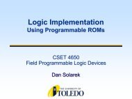
<strong>Introduction</strong> <strong>to</strong> <strong>CPLDs</strong><br />
Complex Programmable<br />
Logic Devices<br />
CSET 4650<br />
Field Programmable Logic Devices<br />
Dan Solarek
Hierarchy of Logic Implementations<br />
<strong>to</strong>day’s focus<br />
Standard<br />
Logic<br />
SPLDs<br />
(e.g., PALs)<br />
Logic<br />
Programmable<br />
Logic Devices<br />
(FPLDs)<br />
<strong>CPLDs</strong><br />
Acronyms<br />
SPLD = Simple Prog. Logic Device<br />
PAL = Prog. Array of Logic<br />
CPLD = Complex PLD<br />
FPGA = Field Prog. Gate Array<br />
ASIC = Application Specific IC<br />
Gate<br />
Arrays<br />
FPGAs<br />
ASIC<br />
Cell-Based<br />
ICs<br />
Full Cus<strong>to</strong>m<br />
ICs<br />
Common Resources<br />
Configurable Logic Blocks (CLB)<br />
Memory Look-Up Look Up Table (LUT)<br />
AND-OR AND OR planes<br />
Simple gates<br />
Input / Output Blocks (IOB)<br />
Bidirectional, latches, latches, inverters, pullup/pulldowns<br />
pullup/pulldowns<br />
Interconnect or Routing<br />
Local, internal feedback, and global<br />
2
PAL Architecture<br />
Recall the PAL device<br />
we studied earlier<br />
PAL16L8<br />
16 inputs<br />
32 input AND gates<br />
up <strong>to</strong> 8 output<br />
functions<br />
Outputs are selectable<br />
between OR/NOR<br />
3
GAL 16V8<br />
An improved PAL<br />
Each output is<br />
programmable as<br />
combinational or<br />
registered<br />
Also has<br />
programmable<br />
output polarity<br />
4
GAL 16V8 Output Logic Macrocell<br />
5
GAL Output Macrocells<br />
4 <strong>to</strong> 1 MUX<br />
00 = registered active low<br />
01 = registered active high<br />
10 = comb. active low<br />
11 = comb. active high<br />
2 <strong>to</strong> 1 MUX<br />
Output feedback<br />
External input<br />
6
GAL Output Macrocells<br />
Registered mode<br />
7
GAL Output Macrocells<br />
combinational mode<br />
8
GAL 22V10<br />
More inputs<br />
More product terms<br />
More flexibility<br />
9
Why <strong>CPLDs</strong>? <strong>CPLDs</strong><br />
For larger applications, we could simply increase the number<br />
of inputs and outputs in a conventional SPLD …<br />
e.g., 16V8 → 20V8 → 22V10<br />
why not keep this trend going → 32V16 → 128V64 ?<br />
Problems:<br />
n times the number of inputs and outputs requires n 2 as much chip<br />
area → <strong>to</strong>o costly<br />
logic gets slower as number of inputs <strong>to</strong> AND array increases<br />
Solution:<br />
multiple PLDs with a relatively small (fast) programmable<br />
interconnect<br />
less general than a single large PLD, but we can use software <strong>to</strong><br />
partition our design in<strong>to</strong> smaller PLD blocks<br />
10
<strong>CPLDs</strong><br />
To create a CPLD device:<br />
put a lot of Simple PLDs on the same chip<br />
add “wires wires” between them whose connections can be<br />
programmed (interconnect)<br />
use fuse/EEPROM technology for the connections<br />
Comparing <strong>CPLDs</strong> <strong>to</strong> FPGAs: FPGAs<br />
CPLD devices are faster, cheaper and have fewer gates<br />
than FPGAs<br />
Meant for interfacing rather than heavy computation<br />
Include built-in built in flash memory<br />
FPGAs need external memory<br />
11
PLCC Package With Socket<br />
Printed circuit board<br />
Plastic Leaded Chip Carrier<br />
12
Examples of <strong>CPLDs</strong><br />
Examples of <strong>CPLDs</strong> and high pin count package types<br />
13
Programming Complex PLDs<br />
Some <strong>CPLDs</strong> are programmed using a PAL<br />
programmer<br />
this method becomes inconvenient for devices with<br />
hundreds of pins<br />
A second method of programming<br />
solder the device <strong>to</strong> its printed circuit board<br />
program it with a serial data stream from a personal<br />
computer<br />
the CPLD decodes the data stream and configures itself <strong>to</strong><br />
perform a specified logic function<br />
14
Programming Complex PLDs<br />
Each manufacturer has a proprietary name for its<br />
CPLD programming system.<br />
Lattice calls it "in-system "in system programming"<br />
Proprietary systems are beginning <strong>to</strong> give way <strong>to</strong> a<br />
standard from the Joint Test Action Group (JTAG)<br />
15
CPLD Packaging and Programming<br />
(a) a CPLD in a<br />
Quad Flat Pack<br />
(QFP) IC package<br />
(b) Set up for<br />
programming the<br />
PCB-mounted<br />
CPLD using JTAG<br />
(b)<br />
Printed<br />
circuit board<br />
(a)<br />
(a) CPLD in a Quad Flat Pack (QFP) package<br />
(b) JTAG programming<br />
To computer<br />
16
XSA-100 XSA 100 Board<br />
logic density of<br />
100,000 gates<br />
with Spartan-II Spartan II<br />
FPGA<br />
16-Mbyte 16 Mbyte<br />
synchronous<br />
DRAM<br />
XC9572<br />
interface CPLD<br />
17
XSA-100 XSA 100 Board<br />
External connections <strong>to</strong><br />
the XSA board.<br />
Parallel port for<br />
programming<br />
External power supply<br />
VGA port <strong>to</strong> display<br />
signals<br />
PS/2 port for pointing<br />
operations<br />
18
XSA-100 XSA 100 Board<br />
XC9572XL interface CPLD<br />
19
CPLD Structure and Alternate Names<br />
A Simple PLD (or SPLD) is<br />
usually a PLA or a PAL<br />
A Complex PLD (CPLD) is<br />
an arrangement of multiple<br />
SPLD-like blocks on a single<br />
chip.<br />
Alternative names include:<br />
enhanced PLD (EPLD)<br />
superPAL<br />
megaPAL<br />
20
Structure of a CPLD: A Closer Look<br />
I/O block<br />
I/O block<br />
PAL-like<br />
block<br />
Interconnection wires<br />
PAL-like<br />
block<br />
PAL-like<br />
block<br />
PAL-like<br />
block<br />
I/O block<br />
I/O block<br />
21
Section of a CPLD<br />
22
CPLD Size Comparison<br />
A CPLD is just a collection of individual PLDs on a single<br />
chip<br />
accompanied by a programmable interconnection structure that allows<br />
the PLDs <strong>to</strong> be hooked up <strong>to</strong> each other on-chip<br />
in the same way that a clever designer might do with discrete PLDs<br />
off-chip<br />
For an SPLD, the chip area for n times as much logic is close<br />
<strong>to</strong> n 2 … (think about an n x n square)<br />
For a CPLD, the chip area for n times as much logic is only n<br />
times the area of a single PLD plus the area of the<br />
programmable interconnect structure.<br />
23
<strong>CPLDs</strong><br />
Rising densities/performance and declining prices<br />
become a good choice for many applications<br />
100K gates <strong>to</strong>day<br />
250K+ gates in near future<br />
Low-density Low density CPLD (32 macrocells/44 pins)<br />
5ns logic delays<br />
High-density High density CPLD (128 macrocells/100 pins)<br />
7.5ns logic delays<br />
24
CPLD Components<br />
Primitive or basic cells<br />
The term “primitive primitive” usually refers <strong>to</strong> simple logic cells<br />
such as NAND, NOR, FLIP-FLOPs<br />
FLIP FLOPs, , LATCHES,<br />
BUFFERS, and INVERTERS<br />
Macrocells<br />
also called 'megacells 'megacells'<br />
' or 'supercells 'supercells'<br />
'<br />
offer diversified functions<br />
range from a shift register <strong>to</strong> a complex microprocessor<br />
25
Types of Macrocells<br />
There are two types of macrocells<br />
Hard (Hardware)<br />
Soft (VHDL library)<br />
Soft macrocells are functions comprised of primitive<br />
cells, which are placed and routed along with the<br />
rest of the chip.<br />
No cell layouts exist for the soft macrocells. macrocells<br />
Designers can configure soft macrocells at the time<br />
of instantiation.<br />
26
Hard Macrocells<br />
Hard macrocells implement functions using cus<strong>to</strong>m<br />
design, usually <strong>to</strong> achieve better performance and<br />
transis<strong>to</strong>r densities.<br />
The vendor tests and verifies both the hard<br />
macrocell layout and its function.<br />
Standard cells usually use hard macrocells but in<br />
some special cases gate arrays may also use them.<br />
A hard macrocell provides speed improvement over<br />
a functionally equivalent soft macrocell. macrocell.<br />
Thus the<br />
hard macrocell occupies less area.<br />
27
Who makes the <strong>CPLDs</strong>? <strong>CPLDs</strong><br />
Manufacturer CPLD Products URL<br />
Altera MAX 5000, 7000 & 9000 www.altera.com<br />
Altmel ATF & ATV www.atmel.com<br />
Cypress FLASH370, Ultra37000 www.cypress.com<br />
Lattice ispLSI 1000 <strong>to</strong> 8000 www.latticesemi.com<br />
Philips XPLA www.philips.com<br />
Vantis MACH 1 <strong>to</strong> 5 www.vantis.com<br />
Xilinx XC9500 www.xilinx.com<br />
Lect #14 Rissacher EE365<br />
28
Altera<br />
Product<br />
MAX5000, MAX7000, MAX9000<br />
MAX7000S: In-circuit programmability<br />
Feature<br />
Logic Array Block (LAB)<br />
Programmable Interconnect Array (PIA)<br />
Variable sized OR gate<br />
29
Altera<br />
Altera MAX 7000 Series<br />
(Programmable Interconnect Matrix)<br />
(Logic Array Block)<br />
30
Altera<br />
Altera MAX 7000 Logic Array Block (LAB)<br />
31
Altera<br />
MAX 7000 Macrocell<br />
32
Altera Macrocell<br />
Interconnect<br />
To Other<br />
Macrocells<br />
Invert<br />
Control<br />
Mux<br />
Global<br />
Clock<br />
D Q<br />
Memory<br />
Clock<br />
Control<br />
Mux<br />
Output<br />
Control<br />
Altera Macrocell<br />
Pad<br />
33
Altera<br />
Product<br />
FLASHlogic<br />
Collection of Configurable Function Blocks (CFB).<br />
Feature<br />
On-chip SRAM blocks<br />
In-system programmability<br />
34
Altera<br />
Altera FLASHlogic CPLD<br />
35
AMD<br />
Product<br />
Mach1, Mach2: 22V16 PALs<br />
Mach3, Mach4: 34V16 PALs<br />
Mach5: 34V16 PALs and enhanced speed<br />
Feature<br />
Product term allocation for variable sized OR gate<br />
Output switch matrix for driving any of the I/O pins<br />
connected <strong>to</strong> the PAL block<br />
36
AMD<br />
Structure of AMD Mach 4 CPLD<br />
37
AMD<br />
AMD Mach 4 PAL-like(34V16) Block<br />
38
Lattice<br />
Product<br />
pLSI, ispLSI<br />
isp = in-system programmability<br />
3000,4000,5000 series<br />
Feature<br />
Generic Logic Block (GLB)<br />
Global Routing Pool (GRP)<br />
39
Lattice<br />
Lattice pLSI Architecture<br />
40
Cypress<br />
Product<br />
FLASH370<br />
Feature<br />
Generic Logic Block (GLB)<br />
Programmable Interconnect Matrix (PIM)<br />
relatively more I/Os<br />
# of macrocells = # of bi-directional I/O pins<br />
41
Cypress<br />
Architecture of Cypress FLASH370 <strong>CPLDs</strong><br />
42
Xilinx<br />
Product<br />
XC7000 Series<br />
XC7200 Series<br />
– Each block has 9 macrocells<br />
– Each macrocells includes two OR-gates<br />
– Each OR-gates is input <strong>to</strong> a two-bit ALU<br />
XC7300 Series : Enhanced version of 7200<br />
XC9500 Series<br />
In-system programmability<br />
43
Xilinx: Xilinx:<br />
XC9500 Device Family<br />
XC9536 XC9572 XC95108 XC95144 XC95216 XC95288<br />
Macrocells 36 72 108 144 216 288<br />
Usable Gates 800 1,600 2,400 3,200 4,800 6,400<br />
Registers 36 72 108 144 216 288<br />
t PD (ns) 5 7.5 7.5 7.5 10 10<br />
t SU (ns) 3.5 4.5 4.5 4.5 6.0 6.0<br />
t CO (ns) 4.0 4.5 4.5 4.5 6.0 6.0<br />
f CNT (MHz) 100 125 125 125 111.1 111.1<br />
f SYSTEM (MHz) 100 83.3 83.3 83.3 66.7 66.7<br />
Note:<br />
f CNT = Operating frequency for 16-bit counters<br />
f SYSTEM = Internal operating frequency for general purpose system designs spanning<br />
multiple FBs.<br />
44
Xilinx<br />
Architecture of Xilinx 9500 <strong>CPLDs</strong><br />
45
Xilinx: Xilinx:<br />
XC9500 Device Family<br />
Each XC9500 device is a subsystem consisting of multiple<br />
Function Blocks (FBs) and I/O Blocks (IOBs) fully<br />
interconnected by the FastCONNECT switch matrix.<br />
The IOB provides buffering for device inputs and outputs.<br />
Each FB provides programmable logic capability with 36<br />
inputs and 18 outputs.<br />
The FastCONNECT switch matrix connects all FB outputs<br />
and input signals <strong>to</strong> the FB inputs. For each FB, 12 <strong>to</strong> 18<br />
outputs (depending on package pin-count) and associated<br />
output enable signals drive directly <strong>to</strong> the IOBs.<br />
46
Xilinx: Xilinx:<br />
XC9500 Device Family<br />
47
Xilinx: Xilinx:<br />
XC9500 Device Family<br />
Each Function Block is comprised of 18 independent<br />
macrocells, each capable of a combina<strong>to</strong>rial or registered<br />
function. The FB also receives global clock, output enable,<br />
and set/reset signals.<br />
The FB generates 18 outputs that drive the FastCONNECT<br />
switch matrix. These 18 outputs and their corresponding<br />
output enable signals also drive the IOB.<br />
Logic within the FB is implemented using a sum-of-products<br />
representation. Thirty-six inputs provide 72 true and<br />
complement signals in<strong>to</strong> the programmable AND-array <strong>to</strong><br />
form 90 product terms. Any number of these product terms,<br />
up <strong>to</strong> the 90 available, can be allocated <strong>to</strong> each macrocell by<br />
the product term alloca<strong>to</strong>r.<br />
48
Xilinx: Xilinx:<br />
XC9500 Device Family<br />
Each FB (except for the XC9536) supports local feedback<br />
paths that allow any number of FB outputs <strong>to</strong> drive in<strong>to</strong> its<br />
own programmable AND-array without going outside the FB.<br />
These paths are used for creating very fast counters and state<br />
machines where all state registers are within the same FB.<br />
49
Xilinx: Xilinx:<br />
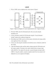
XC9500 Device Family<br />
Each XC9500 macrocell may be individually configured for a<br />
combina<strong>to</strong>rial or registered function. The macrocell and<br />
associated FB logic is shown in Figure 3.<br />
Five direct product terms from the AND-array are available for<br />
use as primary data inputs (<strong>to</strong> the OR and XOR gates) <strong>to</strong><br />
implement combina<strong>to</strong>rial functions, or as control inputs<br />
including clock, set/reset, and output enable. The product term<br />
alloca<strong>to</strong>r associated with each macrocell selects how the five<br />
direct terms are used.<br />
The macrocell register can be configured as a D-type or T-type<br />
flip-flop, or it may be bypassed for combina<strong>to</strong>rial operation.<br />
Each register supports both asynchronous set and reset<br />
operations. During power-up, all user registers are initialized <strong>to</strong><br />
the user-defined preload state (default <strong>to</strong> 0 if unspecified).<br />
50
Xilinx: Xilinx:<br />
XC9500 Device Family<br />
51
Xilinx: Xilinx:<br />
XC9500 Device Family<br />
All global control signals are available <strong>to</strong> each individual macrocell,<br />
including clock, set/reset, and output enable signals.<br />
As shown in Figure 4, the macrocell register clock originates from either<br />
of three global clocks or a product term clock. Both true and complement<br />
polarities of a GCK pin can be used within the device. A GSR input is<br />
also provided <strong>to</strong> allow user registers <strong>to</strong> be set <strong>to</strong> a user-defined state.<br />
52
Xilinx: Xilinx:<br />
XC9500 Device Family<br />
The FastCONNECT switch matrix connects signals <strong>to</strong> the FB<br />
inputs, as shown in Figure 9. All IOB outputs (corresponding<br />
<strong>to</strong> user pin inputs) and all FB outputs drive the<br />
FastCONNECT matrix. Any of these (up <strong>to</strong> a FB fan-in limit<br />
of 36) may be selected, through user programming, <strong>to</strong> drive<br />
each FB with a uniform delay.<br />
The FastCONNECT switch matrix is capable of combining<br />
multiple internal connections in<strong>to</strong> a single wired-AND output<br />
before driving the destination FB. This provides additional<br />
logic capability and increases the effective logic fan-in of the<br />
destination FB without any additional timing delay. This<br />
capability is available for internal connections originating<br />
from FB outputs only. It is au<strong>to</strong>matically invoked by the<br />
development software where applicable.<br />
53
Xilinx: Xilinx:<br />
XC9500 Device Family<br />
54
Xilinx: Xilinx:<br />
XC9500 Device Family<br />
The I/O Block (IOB) interfaces between the internal<br />
logic and the device user I/O pins. Each IOB<br />
includes an input buffer, output driver, output enable<br />
selection multiplexer, and user programmable<br />
ground control. See Figure 10 for details.<br />
The input buffer is compatible with standard 5 V<br />
CMOS, 5 V TTL and 3.3 V signal levels. The input<br />
buffer uses the internal 5 V voltage supply (V<br />
CCINT ) <strong>to</strong> ensure that the input thresholds are<br />
constant and do not vary with the V CCIO voltage.<br />
55
Xilinx: Xilinx:<br />
XC9500 Device Family<br />
56
Xilinx: Xilinx:<br />
XC9500 Device Family<br />
XC9500 devices are programmed in-system via a<br />
standard 4-pin JTAG pro<strong>to</strong>col. In-system<br />
programming offers quick and efficient design<br />
iterations and eliminates package handling.<br />
The Xilinx development system provides the<br />
programming data sequence using a Xilinx<br />
download cable, a third-party JTAG development<br />
system, JTAG-compatible board tester, or a simple<br />
micro-processor interface that emulates the JTAG<br />
instruction sequence.<br />
57
Xilinx: Xilinx:<br />
XC9500 Device Family<br />
XC9500 devices can also be programmed by the<br />
XilinxHW130 device programmer as well as thirdparty<br />
programmers. This provides the added<br />
flexibility of using pre-programmed devices during<br />
manufacturing, with an in-system programmable<br />
option for future enhancements.<br />
58
Xilinx: Xilinx:<br />
XC9500 Device Family<br />
XC9500 devices incorporate advanced data security features which<br />
fully protect the programming data against unauthorized reading or<br />
inadvertent device erasure/reprogramming. Table 3 shows the four<br />
different security settings available.<br />
The read security bits can be set by the user <strong>to</strong> prevent the internal<br />
programming pattern from being read or copied. When set, they also<br />
inhibit further program operations but allow device erase. Erasing the<br />
entire device is the only way <strong>to</strong> reset the read security bit.<br />
The write security bits provide added protection against accidental<br />
device erasure or reprogramming when the JTAG pins are subject <strong>to</strong><br />
noise, such as during system power-up. Once set, the writeprotection<br />
may be deactivated when the device needs <strong>to</strong> be<br />
reprogrammed with a valid pattern.<br />
59
Xilinx: Xilinx:<br />
XC9500 Device Family<br />
60
Xilinx: Xilinx:<br />
XC9500 Device Family<br />
Basic Timing Model<br />
61