You also want an ePaper? Increase the reach of your titles
YUMPU automatically turns print PDFs into web optimized ePapers that Google loves.
- Subject to modifications -<br />
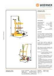
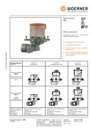
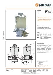
<strong>Pump</strong> with bung-hole<br />
2<br />
4<br />
<strong>Pump</strong> <strong>unit</strong> <strong>GMZ</strong>-E<br />
111.460<br />
<strong>Pump</strong> with barrel lid<br />
1 = Elements<br />
2 = Barrel lid<br />
3 = Ring screws<br />
(for 200 l only)<br />
4 = Grease follow-up<br />
plate<br />
(for barrel dimensions<br />
see 4th page)<br />
EUG<strong>EN</strong> WOERNER GmbH & Co. KG<br />
Postfach 1661 DE-97866 Wertheim<br />
Hafenstrasse 2 DE-97877 Wertheim<br />
Tel. +49 (0) 9342 803-0 info@woerner.de<br />
Fax.+49 (0) 9342 803-202 www.woerner.de<br />
1<br />
3<br />
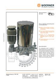
<strong>Pump</strong> <strong>unit</strong><br />
<strong>GMZ</strong>-E<br />
<strong>Pump</strong> used to supply oil and grease from a<br />
barrel directly through a lid-hole or a bunghole.<br />
Technical data:<br />
Delivery volume per stroke:<br />
<strong>Pump</strong> element "6": 0,08 cm³/stroke<br />
1)<br />
Number of strokes:<br />
-1<br />
22 min<br />
Number of pump elements: 1 ... 15<br />
Delivery pressure:<br />
Lubricant:<br />
350 bar<br />
Oil: Viscosity > 180 cP<br />
(200 cSt, 26 °E)<br />
Grease: Class NLGI 000 ... 2<br />
from class 1 onward follow-up plate<br />
required additionally.<br />
Lubricant: The intended lubricant must be<br />
suitable for use with centralized lubrication<br />
equipment.<br />
Pipe connection: 6, 8 and 10 mm<br />
Temperature range: -10 ... +40 °C<br />
Lower or higher temperatures by<br />
request.<br />
Seal material: NBR (Perbunan)<br />
Electrical data:<br />
Motor:<br />
Voltage:<br />
at 50Hz D/Y: 220-240/380-415 V<br />
at 60Hz Y:<br />
Current:<br />
440-460 V<br />
at 50Hz D/Y: 1,21/0,7 A<br />
at 60Hz D/Y: 1,07/0,62 A<br />
1)<br />
Rated speed:<br />
-1<br />
1000 min<br />
Power rating: 180 W<br />
Protection type: IP55<br />
Insulation class: F<br />
(Other motors upon request)<br />
Level monitor: (pressure switch)<br />
Switching voltage AC: at max. 230 VAC<br />
at max. 5 A<br />
inductive at max. 3 A<br />
Switching voltage DC: at max. 125 VDC<br />
at max. 0,4 A<br />
inductive at max. 0,05 A<br />
Plug connector: DIN 43650<br />
Protection type: IP65<br />
Connection diagram:<br />
Switch position<br />
shown represents<br />
"barrel empty"<br />
(pump casing<br />
depressurized)<br />
1)<br />
With standard motor and 50 Hz frequency<br />
Leaflet-No. 0668.08.11 <strong>EN</strong><br />
Replaces No. 0668 09.10 <strong>EN</strong><br />
Page 1 of 6
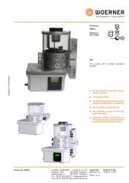
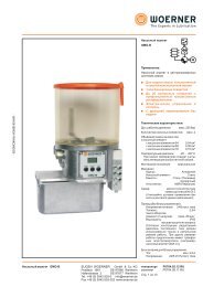
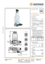
2<br />
1<br />
1 - <strong>Pump</strong> element<br />
2 - Vent screw G 1/4<br />
3 - Gear motor<br />
4 - Level control<br />
5 - Eccentric shaft<br />
6 - <strong>Pump</strong> casing<br />
7 - Pressure ring<br />
8 - Threaded connection G2<br />
9<br />
10<br />
11<br />
12<br />
13<br />
14<br />
Phase 2 Phase 1 and 3<br />
9 - Control piston<br />
10 - Check valve<br />
11 - Delivery piston<br />
12 - Intermediate chamber<br />
13 - Pressure spring<br />
14 - Check valve<br />
15 - Delivery pump<br />
3<br />
4<br />
5<br />
6<br />
7<br />
8<br />
<br />
15<br />
EUG<strong>EN</strong> WOERNER GmbH & Co. KG<br />
Postfach 1661 DE-97866 Wertheim<br />
Hafenstrasse 2 DE-97877 Wertheim<br />
Tel. +49 (0) 9342 803-0 info@woerner.de<br />
Fax.+49 (0) 9342 803-202 www.woerner.de<br />
Operation of pump:<br />
The barrel pump consists of the following<br />
components:<br />
Feed pump (15), pump housing (6), pump<br />
elements (1) and drive motor (3). The feed<br />
pump (15) is powered by the drive motor (3)<br />
via the vertical eccentric shaft (5).<br />
Phase 1<br />
During the suction stroke the delivery piston<br />
(11) forced downward by the control piston<br />
(9) is pressed upward again by the<br />
compression spring (13). The vacuum<br />
resulting in the intermediate chamber (12)<br />
causes the lubricant to be drawn in via the<br />
non-return valve (14).<br />
Phase 2<br />
During the next half revolution of the control<br />
piston (9), the delivery piston (11) is<br />
forced downward again and the lubricant<br />
contained in the intermediate chamber (12)<br />
is delivered in upward direction via the nonreturn<br />
valve (10).<br />
Phase 3<br />
Further rotation of the control spool (9)<br />
through 180° results in a new suction stroke<br />
and the non-return valve (10) closing at the<br />
same time enables the spring-loaded<br />
delivery piston (11) to force the lubricant<br />
above it into the upper pump housing (6).<br />
The level monitor (4) signals "barrel empty"<br />
when no more lubricant is delivered by the<br />
feed pump (15), however there is still<br />
lubricant left in the pump housing.<br />
The vertical eccentric shaft (5) drives a<br />
pressure ring (7) to which the pump<br />
elements (1) are attached. Due to the<br />
eccentricity of the pressure ring (7) each<br />
delivery piston performs one constant<br />
delivery and suction stroke per pump shaft<br />
revolution.<br />
The pump elements (1) draw accurately<br />
metered quantities of lubricant (dependent<br />
on element adjustment) from the lubricant<br />
reservoir in the pump housing (6).<br />
Leaflet-No. 0668 <strong>EN</strong><br />
Page 2 of 6<br />
- Subject to modifications -
- Subject to modifications -<br />
6<br />
Suction<br />
stroke<br />
7<br />
Pressure<br />
stroke<br />
PMF pump elements assembly:<br />
When fitting another pump element into the<br />
reciprocating pump, please proceed as<br />
shown in the sketch beside: With the<br />
delivery piston being approximately pulled<br />
out half, insert the pump element diagonally<br />
upward into the casing's reception hole.<br />
Insertion and operation will be easier when<br />
the hole that serves to accommodate the<br />
delivery piston is filled with grease. Do not<br />
put the pump element into horizontal<br />
position and screw in, unless the delivery<br />
piston's head touches the pressure ring and<br />
5<br />
R<br />
3<br />
Delivery volume<br />
2<br />
4<br />
ratches into the latter's groove.<br />
When demounting, pull the pump element<br />
cautiously out of the casing such that the<br />
delivery piston will remain within the pump<br />
element.<br />
EUG<strong>EN</strong> WOERNER GmbH & Co. KG<br />
Postfach 1661 DE-97866 Wertheim<br />
Hafenstrasse 2 DE-97877 Wertheim<br />
Tel. +49 (0) 9342 803-0 info@woerner.de<br />
Fax.+49 (0) 9342 803-202 www.woerner.de<br />
1<br />
<strong>Pump</strong> elements mode of operation:<br />
Suction stroke is accomplished by delivery<br />
piston 1 and control piston 2.<br />
In this<br />
process, delivery piston 1 is actuated by the<br />
eccentric shaft, whilst the spring actuates<br />
control piston 2.<br />
The control piston closes<br />
pressure hole 3 and is kept in a certain<br />
position as determined by the preset<br />
delivery volume. The delivery piston moves<br />
on, causing a vacuum to be built up in the<br />
proportioning space. When the delivery<br />
piston has opened suction hole 4,<br />
lubricant<br />
starts to be sucked from the reservoir.<br />
In case of pressure stroke,<br />
delivery piston<br />
1 moves to the left. In this motion, suction<br />
hole 4 is closed and control piston 2<br />
displaced by virtue of the lubricant being<br />
available in between the delivery and<br />
control pistons until it releases pressure<br />
hole 3 and the lubricant is delivered through<br />
the delivery piston to the outlet. The pump<br />
elements are delivered with maximum<br />
delivery volume, i.e. they are set to full<br />
stroke.<br />
The delivery volume can be adjusted<br />
continuously between 25 and 100% of the<br />
nominal delivery volume. After having<br />
removed lock screw 7,<br />
the stroke is to be<br />
changed by means of the enclosed spanner<br />
through adjustment nipple 6.<br />
When turning<br />
the nippe to the right, delivery volume will<br />
decrease. At the adjustment nipple, there is<br />
a hexagon against which a spring loaded<br />
piston is pressing radially. Thus, any<br />
independent change of the delivery volume<br />
will be prevented. At the same time, the<br />
latching serves as a measure for setting the<br />
delivery volume.<br />
Six latches equal one rotation of the<br />
adjustment nipple and a reduction of the<br />
nominal delivery volume by 33%. 14 latches<br />
(minimum) equal a delivery volume<br />
reduction down to 25% of the nominal<br />
delivery volume.<br />
Leaflet-No. 0668 <strong>EN</strong><br />
Page 3 of 6
Operating inst<strong>ru</strong>ctions:<br />
Direction of motor rotation:<br />
When connecting the motor make sure the<br />
drive shaft rotates counter-clockwise when<br />
viewing the fan.<br />
The gear is maintenance-free filled with<br />
synthetic oil for its whole working life.<br />
Venting:<br />
Before putting the pump into operation<br />
remove the plug (2) to vent the pump<br />
housing.<br />
The lubricant supply lines must be clean<br />
and allow free passage. Do not connect the<br />
lines to the lubrication point before the<br />
lubricant flows out bubble-free.<br />
Version min.<br />
inner height<br />
h<br />
1<br />
2<br />
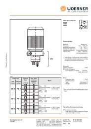
Order-designation:<br />
<strong>Pump</strong> <strong>unit</strong><br />
Version Barrel lid<br />
Barrel dimensions<br />
Inner<br />
diameter<br />
d<br />
Leak testing:<br />
Inspect all supply line connections for leaks.<br />
No lubricant return lines may be connected<br />
to the pump <strong>unit</strong>.<br />
Follow-up plate:<br />
Caution! When using the follow-up plate, do<br />
not install it in barrels having deep indentations.<br />
After installation press the <strong>ru</strong>bber seal<br />
against the barrel wall.<br />
Caution:<br />
Do not use any barrels with foil<br />
inlays!<br />
max. outer<br />
diameter<br />
D<br />
suitable for barrel with<br />
nominal filling capacity<br />
850 550 ... 570 610 200 l<br />
acc. to DIN 6644<br />
540 340 ... 360 385 50 l<br />
acc. to DIN 6644<br />
<strong>GMZ</strong>-E . B<br />
internal<br />
Grease follow-up<br />
plate<br />
Element "6"<br />
with pipe connection<br />
Motor<br />
1 with D with F Ø 6 Ø 8 Ø 10 A<br />
for barrel<br />
Number Number Number Standard motor<br />
200 l without 0 without 0<br />
(technical data<br />
0 ... 15 0 ... 15 0 ... 15 see 1th page)<br />
<br />
2 with D<br />
S<br />
for barrel<br />
without 0 max. 15 elements possible<br />
Special motor<br />
50 l without 0<br />
(please state data)<br />
Accessories: Function indication<br />
Instead of a pump element<br />
Use: Optical operating control<br />
Function, see leaflet-no. 0809<br />
Purchase-no.: 752.528-69<br />
EUG<strong>EN</strong> WOERNER GmbH & Co. KG<br />
Postfach 1661 DE-97866 Wertheim<br />
Hafenstrasse 2 DE-97877 Wertheim<br />
Tel. +49 (0) 9342 803-0 info@woerner.de<br />
Fax.+49 (0) 9342 803-202 www.woerner.de<br />
approx. 520<br />
Ordering-example:<br />
<strong>Pump</strong> <strong>unit</strong> <strong>GMZ</strong>-E; version for 200 l barrel;<br />
with barrel cover; without transfer plate; 8<br />
pcs. of element 6 with pipe connector Ø 6;<br />
standard motor<br />
Order-designation:<br />
<strong>GMZ</strong>-E.B / 1 / D / 0 / 8 / 0 / 0 / A<br />
Leaflet-No. 0668 <strong>EN</strong><br />
Page 4 of 6<br />
- Subject to modifications -
- Subject to modifications -<br />
3<br />
7<br />
8<br />
11<br />
1<br />
2<br />
9<br />
10<br />
EUG<strong>EN</strong> WOERNER GmbH & Co. KG<br />
Postfach 1661 DE-97866 Wertheim<br />
Hafenstrasse 2 DE-97877 Wertheim<br />
Tel. +49 (0) 9342 803-0 info@woerner.de<br />
Fax.+49 (0) 9342 803-202 www.woerner.de<br />
4<br />
5<br />
6<br />
Spare parts:<br />
Item Designation Order-no.<br />
1 Drive motor 948.093-95<br />
0,18kW, 230/400V, 50Hz<br />
other motors<br />
upon request<br />
2 Pressure switch 111.467-45<br />
3 Drive complete 111.425-65K<br />
4 Adjusting spanner 110.004-65<br />
5 Ring piece 6 110.070-65<br />
Ring piece 8 110.080-65<br />
Ring piece 10 110.090-65<br />
6 <strong>Pump</strong> element DMF-A/6/0/0/1/1/0<br />
7 Barrel lid<br />
Version 1 111.436-25<br />
Version 2 111.461-45<br />
8 Coupling tube<br />
Version 1 111.395-65<br />
Version 2 111.464-65<br />
9<br />
Outer tube<br />
Version 1 111.397-45<br />
Version 2 111.463-45<br />
10 Grease follow-up plate<br />
Version 1 111.451-65<br />
11 Feed pump 111.385-65<br />
complete<br />
Set of seals<br />
<strong>Pump</strong> 111.425-64K<br />
Leaflet-No. 0668 <strong>EN</strong><br />
Page 5 of 6
Important information on this publication<br />
Reproduction, also in extracts, only permitted with the approval of the firm of EUG<strong>EN</strong><br />
WOERNER GmbH & Co. KG.<br />
All the information in this publication has been examined for correctness with great care.<br />
Nevertheless, WOERNER cannot assume any liability for losses or damage resulting<br />
directly or indirectly from the application of the information contained in this publication.<br />
All products from WOERNER may only be used as intended and corresponding to the<br />
information in this publication.<br />
For products supplied with operating inst<strong>ru</strong>ctions, the additional directives and information<br />
contained in them are to be complied with.<br />
Materials deviating from those mentioned in this publication and the technical documents<br />
which further apply may only be poured into and processed in the appliances and systems<br />
manufactured and supplied by WOERNER by following agreement with and written<br />
approval by WOERNER.<br />
The safety and danger information stated in the safety data sheets of the substances used<br />
must be taken into account at all costs.<br />
Transportation of gases, liquefied gases, gases under pressure, vapours and liquids, the<br />
vapour pressure of which is more than 0,5 bar above normal atmospheric pressure<br />
(1013 mbar) at the maximum admissible temperature, of easy inflammable or explosive<br />
media as well as transportation of foodstuffs is forbidden.<br />
Information on EU Directive 2002/95/EC (RoHS)<br />
With Directive 2002/95/EC of January 27, 2003, for the limitation of the use of certain<br />
hazardous substances in electrical and electronic devices (RoHS) material bans come into<br />
effect from July 2006 for electrical and electronic devices newly placed on the market for<br />
lead, cadmium, hexavalent chromium, mercury and brominated flame retardants.<br />
In its controls and switching devices, WOERNER only uses materials which fulfil the criteria<br />
of EU Directive 2002/95/EC.<br />
To the extent that hexavalent chromium has been used as corrosion protection in the parts<br />
which we produce ourselves, it has already been replaced by other environmentally<br />
tolerable protective measures.<br />
The mechanical devices supplied by WOERNER are not affected by EU Directive<br />
2002/95/EC as they are appliances added or installed on "large-scale stationary industrial<br />
tools" (cf. EU Directive 2002/96/EC,Annex IA).<br />
But as WOERNER is conscious of its responsibility towards the environment, we shall also<br />
use materials fulfilling the requirements of the Directive for devices not covered by EU<br />
Directive 2002/95/EC as soon as they are generally available and their use is technically<br />
possible.<br />
EUG<strong>EN</strong> WOERNER GmbH & Co. KG<br />
Postfach 1661 DE-97866 Wertheim<br />
Hafenstrasse 2 DE-97877 Wertheim<br />
Tel. +49 (0) 9342 803-0 info@woerner.de<br />
Fax.+49 (0) 9342 803-202 www.woerner.de<br />
Leaflet-No. 0668 <strong>EN</strong><br />
Page 6 of 6<br />
- Subject to modifications -