Mining_Methods_UnderGround_Mining - Mining and Blasting
Mining_Methods_UnderGround_Mining - Mining and Blasting
Mining_Methods_UnderGround_Mining - Mining and Blasting

You also want an ePaper? Increase the reach of your titles
YUMPU automatically turns print PDFs into web optimized ePapers that Google loves.
el SOldadO, CHile<br />
hundred metres above the valley floor.<br />
Today, the main entry is located at -100<br />
level (730 m asl) <strong>and</strong> the haulage level is<br />
at 300 m below datum (530 m asl). The<br />
mine has been developed by a network<br />
of sublevels, providing access to the<br />
tops <strong>and</strong> bottoms of the mining areas.<br />
Sublevels are linked by ramps, with a<br />
maximum slope of 15%. Ore is loaded<br />
directly into ore passes with an overall<br />
capacity of 10,000 to 30,000 t, which<br />
connect sub levels with the haulage<br />
level. This ore is transported to a crusher<br />
located on surface, near the concentrator,<br />
using 50 t-capacity, highway-type<br />
trucks. Some ore is mined below the main<br />
haulage level, <strong>and</strong> this material is transported<br />
directly to the surface crusher<br />
using trucks <strong>and</strong> ramps.<br />
Historically, the massive, but irregular,<br />
orebodies <strong>and</strong> the competent ground<br />
conditions made sublevel open stoping<br />
the preferred mining method. However,<br />
in 1983, fully mechanized sublevel <strong>and</strong><br />
large-diameter blast hole open stope<br />
(SBOS) was introduced as a variation<br />
of the st<strong>and</strong>ard method, enabling an<br />
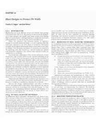
50 to 75 m<br />
Uphole production drilling pattern.<br />
Downhole production drilling pattern.<br />
Parallel hole drilling<br />
45°<br />
Radial hole drilling<br />
45°<br />
AdP 450<br />
50 to 75 m<br />
Nonel<br />
increase in production rates. Nominal<br />
stope dimensions are 30 to 60 mwide,<br />
50 to 100 m-long, <strong>and</strong> up to 100<br />
m-high, though large orebodies are<br />
divided into several units, leaving rib<br />
<strong>and</strong> crown pillars as temporary sup-<br />
port structures. Rib pillars are 30 to 50 m-<br />
wide, <strong>and</strong> crown pillars 25 to 40 m- thick.<br />
The stopes are mined progressively down-<br />
wards by a traditional SBOS method,<br />
<strong>and</strong> are left unfilled. Pillars are subse-<br />
quently recovered by a mass blast technique,<br />
<strong>and</strong> are sometimes designed<br />
to break more than 1 million t of ore<br />
each.<br />
The rock is very competent, <strong>and</strong> the<br />
stope cavities can be left open, sometimes<br />
st<strong>and</strong>ing for 5 or 10 years, depending<br />
on the sector <strong>and</strong> the rock structure.<br />
Smaller stope cavities normally have<br />
stable geometries, with less than 5%<br />
dilution from back extension or wall<br />
failure. However, three large open stopes,<br />
the Santa Clara, California <strong>and</strong><br />
Valdivia Sur stopes, have experienced<br />
controlled structural caving, filling the<br />
existing void <strong>and</strong> breaking through to<br />
the surface. If it is decided to fill a stope,<br />
then waste rock from development is<br />
used.<br />
Production stopes<br />
Production block access is provided by<br />
developing sublevels, with a pattern of<br />
5.0 m x 3.7 m LHD drawpoints at the<br />
base of the stope. Block undercutting is<br />
accomplished with a fan pattern of 60 to<br />
75 mm-diameter holes up to 25 m-long<br />
loaded with ANFO <strong>and</strong> HE boosters.<br />
Slots are made by enlarging a 2.5 x 2.5<br />
m blast hole slot raise, at one end, or in<br />
the middle, of the stope. Blast holes of<br />
165 mm-diameter <strong>and</strong> up to 80 m-long<br />
are drilled with an underh<strong>and</strong> pattern.<br />
Blast size <strong>and</strong> blasting sequence is<br />
defined for each stope, according to<br />
major structural features <strong>and</strong> the proximity<br />
of existing cavities. Dilution control<br />
is improved, <strong>and</strong> blast hole losses<br />
avoided, by carefully considering the<br />
particular geometries created by the intersection<br />
of major discontinuities <strong>and</strong><br />
the free faces of the planned excavation.<br />
Often, faults present geometries which<br />
generate wedges that can slide into the<br />
cavity, affecting fragmentation <strong>and</strong> generating<br />
oversize rock at drawpoints. The<br />
presence of cavities, or simultaneous<br />
mining in nearby locations, also impose<br />
restrictions in the mining sequence <strong>and</strong><br />
size of blast.<br />
Production ore from stopes is loaded<br />
out with 10 cu yd LHDs. One-way distances<br />
of 100 to 150 m are maintained<br />
to orepass tips, which are not equipped<br />
with grizzlies as oversize rock is drilled<br />
<strong>and</strong> blasted in place at the drawpoints.<br />
Orepasses terminate in hydraulicallycontrolled<br />
chutes at the –300 haulage<br />
level, where the 50 t trucks are loaded<br />
with run-of-mine ore or development<br />
waste.<br />
A square pattern of 1.90 m x 1.7 m<br />
split set bolts, 2.05 m-long, in combination<br />
with wire mesh, is used to maintain<br />
working areas free of rock fall, <strong>and</strong> to<br />
protect personnel <strong>and</strong> equipment. This<br />
approach to ground control is not intended<br />
for heavy rock loads or massive<br />
stress-induced instabilities, though<br />
is adequate for local support. Where<br />
needed, cable bolting is used to support<br />
unfavourable geometries, such as<br />
large wedges or low dip bedding layers,<br />
80 underground mining methods<br />
B<br />
A<br />
Á<br />
C´<br />
C