Mining_Methods_UnderGround_Mining - Mining and Blasting
Mining_Methods_UnderGround_Mining - Mining and Blasting
Mining_Methods_UnderGround_Mining - Mining and Blasting

You also want an ePaper? Increase the reach of your titles
YUMPU automatically turns print PDFs into web optimized ePapers that Google loves.
<strong>Mining</strong> <strong>Methods</strong><br />
in Underground <strong>Mining</strong><br />
Second edition 2007<br />
www.atlascopco.com
When safety comes first<br />
Add a solid body hydraulic breaker to a proven folding boom<br />
on the world’s most tested underground carrier, <strong>and</strong> you have<br />
the Scaletec MC – a scaling rig for tunnelling <strong>and</strong> mining<br />
applications. Scaletec MC will give you higher productivity,<br />
less accidents, <strong>and</strong> take you a giant step along the route<br />
towards full mechanization.<br />
Committed to your superior productivity.<br />
Atlas Copco Rock Drills AB<br />
www.atlascopco.com
Contents<br />
Foreword<br />
2 Foreword by Hans Fernberg M Sc<br />
<strong>Mining</strong> Engineering, Senior Adviser,<br />
Atlas Copco Rock Drills AB<br />
Talking Technically<br />
3 Trends in underground mining<br />
7 Geology for underground mining<br />
13 Mineral prospecting <strong>and</strong> exploration<br />
17 Finding the right balance in exploration drilling<br />
21 Underground mining infrastructure<br />
25 Principles of raise boring<br />
29 Mechanized bolting <strong>and</strong> screening<br />
33 <strong>Mining</strong> in steep orebodies<br />
39 <strong>Mining</strong> in flat orebodies<br />
43 Backfilling for safety <strong>and</strong> profit<br />
46 Atlas Copco rock bolts for mining<br />
Case Studies<br />
47 Innovative mining at Garpenberg<br />
53 Changing systems at Zinkgruvan<br />
59 Increasing outputs at LKAB iron ore mines<br />
63 From surface to underground at Kemi<br />
69 <strong>Mining</strong> magnesite at Jelšava<br />
73 All change for Asikoy copper mine<br />
77 <strong>Mining</strong> challenge at El Soldado<br />
83 Pioneering mass caving at El Teniente<br />
91 Boxhole boring at El Teniente<br />
97 Modernization at Sierra Mir<strong>and</strong>a<br />
99 Mount Isa mines continues to exp<strong>and</strong><br />
105 High speed haulage at Stawell<br />
109 Sublevel stoping at Olympic Dam<br />
115 Improved results at Meishan iron ore mine<br />
119 Mechanized mining in low headroom at Waterval<br />
121 Large scale copper mining adapted to lower seams<br />
125 Underground mining of limestone <strong>and</strong> gypsum<br />
129 Sub level caving for chromite<br />
133 Getting the best for Peñoles<br />
137 Keeping a low profile at Panasqueira<br />
Front cover: Headframe at Australia´s Golden Grove mine.<br />
All product names such as Boomer, Boltec, Simba, COP, Scooptram<br />
<strong>and</strong> Swellex are registered Atlas Copco trademarks. For machine<br />
specifications contact your local Atlas Copco Customer Center or<br />
refer to www.atlascopco.com/rock<br />
Produced by tunnelbuilder ltd for Atlas Copco Rock Drills AB, SE-701 91 Örebro, Sweden, tel +46 19 670 -7000, fax - 7393.<br />
Publisher Ulf Linder ulf.linder@se.atlascopco.com Editor Mike Smith mike@tunnelbuilder.com Senior Adviser Hans Fernberg<br />
hans.fernberg@se.atlascopco.com Picture Editor Patrik Johansson patrik.johansson@se.atlascopco.com<br />
Contributors Marcus Eklind, Patrik Ericsson, Jan Jönsson, Mathias Lewén, Gunnar Nord, Björn Samuelsson,<br />
all name.surname@se.atlascopco.com, Adriana Potts adriana.potts@ntlworld.com, Kyran Casteel kyrancasteel@aol.com,<br />
Magnus Ericsson magnus.ericsson@rmg.se. The editor gratefully acknowledges extracts from Underground <strong>Mining</strong> <strong>Methods</strong><br />
– engineering fundamentals <strong>and</strong> international case studies by William A Hustrulid <strong>and</strong> Richard L Bullock, published by SME,<br />
details from www.smenet.org<br />
Designed <strong>and</strong> typeset by ahrt, Örebro, Sweden<br />
Printed by Welins Tryckeri AB, Örebro, Sweden<br />
Copyright 2007 Atlas Copco Rock Drills AB.<br />
Digital copies of all Atlas Copco reference editions can be ordered from the<br />
publisher, address above, or online at www.atlascopco.com/rock. Reproduction<br />
of individual articles only by agreement with the publisher.<br />
underground mining methods 1
Foreword<br />
In history, before miners had access to productive equipment<br />
<strong>and</strong> blasting agents, mining was hard <strong>and</strong> hazardous manual<br />
work. The idea of excavating large volumes of rock to access<br />
even the richest mineral zones was not feasible, <strong>and</strong>, as a result,<br />
ore veins were selectively followed, predominantly close<br />
to the surface, or inside mountains. During the past century,<br />
introduction of diesel power <strong>and</strong> electricity, combined with<br />
new methods of mineral dressing, paved the way for large<br />
scale open pit mining, <strong>and</strong> later for mechanized underground<br />
mining. Nevertheless, the largest quantities of ore are still<br />
excavated from surface deposits.<br />
Atlas Copco, as an equipment supplier with a truly global<br />
presence, has been at the forefront of technical <strong>and</strong> innovative<br />
development. From pneumatic to hydraulic power, from<br />
railbound to trackless haulage, from h<strong>and</strong>held to rig mounted<br />
rock drills, <strong>and</strong> lately, from manual to computerized operation,<br />
Atlas Copco expertise is making mining safer <strong>and</strong> more<br />
efficient.<br />
Today, the mining industry, in its continuous battle for profitability,<br />
is getting more <strong>and</strong> more capital intensive. Technical<br />
development, especially in underground mining, has been<br />
extremely rapid during the past decade. Less labour is required,<br />
<strong>and</strong> safety <strong>and</strong> environmental aspects are of prime<br />
importance.<br />
Growing dem<strong>and</strong> for metals has resulted in today’s world wide<br />
exploration <strong>and</strong> mining boom. However, mining companies<br />
have experienced increasing difficulties in recruiting skilled<br />
labour to work in remote mining communities. This has led<br />
to a stronger involvement from contractors now carrying out<br />
tasks beyond the more traditional shaft sinking operations.<br />
Today, contractors get engaged in all kinds of mine infrastructure<br />
works such as drifting, both inside <strong>and</strong> outside<br />
the orebodies, <strong>and</strong> might also be involved in production <strong>and</strong><br />
mine planning, as well as scheduling. The miners, traditionally<br />
focusing on maximizing the utilization of their equipment<br />
Hans Fernberg<br />
M Sc <strong>Mining</strong> Engineering<br />
Senior Adviser<br />
Atlas Copco Rock Drills AB<br />
hans.fernberg@se.atlascopco.com<br />
mine-wide, are benefiting from experience gained by tunnel<br />
contractors, who frequently have to concentrate their focus<br />
on a single tunnel face. This makes the latter more suited for<br />
high-speed ramp <strong>and</strong> drift development, <strong>and</strong> is one reason<br />
why contractors are increasingly being employed by mine<br />
owners on this type of work. Also, contractors bring with<br />
them a range of skills developed under various conditions in<br />
multiple locations, <strong>and</strong> frequently have the latest <strong>and</strong> most<br />
sophisticated equipment immediately available. Gone are the<br />
days when contractors got only the jobs that the mine management<br />
could not do, or simply didn’t want to do. Nowadays, it<br />
is normal for a contractor to bring specialist skills <strong>and</strong> equipment<br />
to the project, <strong>and</strong> for the mine to get its development<br />
work completed faster <strong>and</strong> cheaper than by doing it itself.<br />
After all, when bringing mines to production, time <strong>and</strong> cost<br />
are crucial factors in their viability.<br />
When designing, manufacturing, selling <strong>and</strong> servicing Atlas<br />
Copco equipment, we commit ourselves to achieving the highest<br />
productivity, <strong>and</strong> the best return on customer investment.<br />
Only by being close to customers, by sharing their problems<br />
<strong>and</strong> underst<strong>and</strong>ing their methods <strong>and</strong> applications, do we earn<br />
the opportunity to be the leading manufacturer, <strong>and</strong> the natural<br />
first choice.<br />
Our main ambition with this book is to stimulate technical<br />
interchange between all people with a special interest in this<br />
fascinating business. These include, in particular, underground<br />
miners, managers <strong>and</strong> consultants, universities, <strong>and</strong> our own<br />
sales <strong>and</strong> marketing organization.<br />
The various cases from leading mines around the world illustrate<br />
how geological <strong>and</strong> geotechnical conditions, never being<br />
identical, give birth to new <strong>and</strong> more successful variants of<br />
mining methods. We hope that some of this material will<br />
result in exp<strong>and</strong>ed contacts between mining companies in<br />
their battle to be more competitive <strong>and</strong> profitable.<br />
2 underground mining methods
<strong>Mining</strong> TrendS<br />
Trends in underground mining<br />
Boom time in<br />
mining<br />
The mining boom continues<br />
unabated. After a difficult ending<br />
to the 20th century, with metal<br />
prices trending downwards<br />
for almost 30 years, the global<br />
mining industry recovered in<br />
the early 2000s. Some observers<br />
claim that the industry will see a<br />
long period of increasing metal<br />
prices <strong>and</strong>, although developments<br />
will continue to be cyclical,<br />
there are predictions of a “super<br />
cycle”. Already it is obvious that<br />
the present boom is something<br />
extraordinary in that it has lasted<br />
longer than previous booms in<br />
the late 1970s <strong>and</strong> the early 1950s.<br />
An almost insatiable dem<strong>and</strong> for<br />
metals has been created by the<br />
unprecedented economic growth<br />
in several emerging economies<br />
led by China, with India <strong>and</strong><br />
Russia trailing not far behind. The<br />
distribution of the value of metal<br />
production at the mine stage is<br />
shown in figure 2 on page 4 page.<br />
China <strong>and</strong> Australia are competing<br />
for first place with roughly 10 per-<br />
cent each. Some economic theoretitians,<br />
active during the late<br />
1980s, who claimed that economic<br />
growth could take place with-<br />
out metals have been proved utterly<br />
wrong.<br />
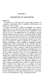
Stable growth<br />
Investments into new mines have increased<br />
dramatically <strong>and</strong> all indicators<br />
point to a continued high level of project<br />
activities during the next couple of<br />
years, see figure 1.<br />
Whatever the investment activities<br />
or metal prices, the amount of metal<br />
produced every year in global mining<br />
is fairly stable <strong>and</strong> increasing slowly but<br />
steadily. Total volumes of rock <strong>and</strong> ore<br />
h<strong>and</strong>led in the global mining industry<br />
amount to approximately 30,000 Mt/y.<br />
This figure includes ore <strong>and</strong> barren rock<br />
<strong>and</strong> covers metals, industrial minerals<br />
<strong>and</strong> coal. Roughly 50% are metals, coal<br />
about 45%, <strong>and</strong> industrial minerals<br />
account for the remainder.<br />
Dynamic growth in China.<br />
Figure 1: <strong>Mining</strong> projects under construction. (Raw Materials Data 2007)<br />
M USD<br />
30 000<br />
25 000<br />
20 000<br />
15 000<br />
10 000<br />
5 000<br />
Trends<br />
Trends<br />
2001 2002 2003 2004 2005 2006<br />
underground mining methods 3
karta sid 2.pdf 9/18/07 9:05:34 PM<br />
Metal ore<br />
<strong>Mining</strong> TrendS<br />
Metal shares of total value gold copper iron ore nickel lead zinc PGMs diamonds other<br />
Value of metal production at mines. (Raw Materials Data 2007)<br />
Global metal ore production is around<br />
5,000 Mt/y. Open pit mining accounts<br />
for some 83% of this, with underground<br />
methods producing the remaining 17%.<br />
Barren rock production from underground<br />
operations is small, not exceeding<br />
10% of total ore production, but the<br />
barren rock production from open pit<br />
operations is significant.<br />
Open pits typically have a strip ratio,<br />
the amount of overburden that has to be<br />
removed for every tonne of ore, of 2.5.<br />
Based on this assumption, the amount<br />
of barren rock produced can be calculated<br />
as some 10,000 Mt/y. In total, the<br />
amount of rock moved in the metals mi-<br />
ning business globally is hence around<br />
15,000 Mt/y. The dominance of open pit<br />
operations stems in terms of the amounts<br />
of rock h<strong>and</strong>led, to a large extent, from<br />
the necessary removal of overburden,<br />
which is often drilled <strong>and</strong> blasted.<br />
By necessity, the open pit operations<br />
are larger than the underground ones.<br />
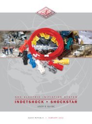
The map below shows the distribution<br />
of metal ore production around the<br />
world, <strong>and</strong> also the split between open<br />
pit <strong>and</strong> underground tonnages.<br />
Metal ore production from open pits (green), underground (red). (Raw Materials Data 2005)<br />
898/77 Mt<br />
1319/117 Mt<br />
open pit underground<br />
Europe + Russia<br />
401/188 Mt<br />
244/175 Mt<br />
750/185 Mt<br />
Total 5 000 Mt<br />
455/85 Mt<br />
Open pit vs underground<br />
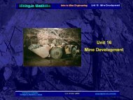
There was a slow trend in the late 20th<br />
century towards open pit production.<br />
Two of the most important reasons for<br />
this were as follows:<br />
Lower ore grades<br />
Due to depletion of the richer ore<br />
bodies, the higher-cost underground<br />
extraction methods are not economic.<br />
See the figure below.<br />
New technologies<br />
The more efficient exploitation of lowergrade<br />
deposits using new equipment <strong>and</strong><br />
new processes, such as the hydrometallurgical<br />
SX-EW methods for copper<br />
extraction, has enabled companies to<br />
work with lower ore grades than with<br />
traditional methods.<br />
Future<br />
Development of new mining technologies<br />
is driven by a range of underlying<br />
factors, which affect all stakeholders.<br />
Mines are getting deeper <strong>and</strong> hotter, <strong>and</strong><br />
are now more often located in harsh en-<br />
vironments.<br />
Legislation, particularly concerning<br />
emissions, <strong>and</strong> increased dem<strong>and</strong>s on<br />
4 underground mining methods
Rock production (2005)<br />
Ore<br />
(Mt)<br />
noise <strong>and</strong> vibration, affect the miners<br />
<strong>and</strong> equipment operators. Safety dem<strong>and</strong>s<br />
have already completely changed<br />
some unit operations, such as rock bolting<br />
<strong>and</strong> scaling. Similar developments<br />
will continue.<br />
Customers dem<strong>and</strong> higher productivity,<br />
<strong>and</strong> there is an increasing focus on<br />
machine availability <strong>and</strong> simpler service<br />
procedures in order to reduce downtime.<br />
Reduction of internal development<br />
<strong>and</strong> production costs by the equipment<br />
Waste<br />
(Mt)<br />
manufacturer promotes new technolo-<br />
gies, as does competition from other<br />
suppliers. In the early years of the 21st<br />
century, new efficient underground me-<br />
thods <strong>and</strong> equipment have made it<br />
possible to turn open pit mines that had<br />
become uneconomical because of their<br />
depth into profitable underground ope-<br />
rations. The orebody in these mines is<br />
usually steep dipping, <strong>and</strong> can be mined<br />
with the most efficient block caving methods.<br />
The competition for l<strong>and</strong> in some<br />
<strong>Mining</strong> TrendS<br />
Metals<br />
Underground 850 85 935 3<br />
Open pit 4 130 10 325 14 500 47<br />
Total<br />
Industrial minerals<br />
4 980 10 410 15 400 50<br />
Underground 65 5 70 0<br />
Open pit 535 965 1 500 5<br />
Total 600 970 1 570 5<br />
Sub total 5 600 11 400 17 000 55<br />
Coal<br />
Underground 2 950 575 3 500 12<br />
Open pit 2 900 7 250 10 000 33<br />
Total 5 850 7 825 13 500 45<br />
Overall total 11 450 19 225 30 700 100<br />
Assumptions: 10% waste in underground metal <strong>and</strong> industrial mineral operations. Strip ratio (overburden/ore) in open<br />
pit metal operations is 2.5. The strip ratio in industrial minerals is 1.8. For coal, underground barren rock is set at 20%, <strong>and</strong> the strip<br />
ratio in open-pit mines is 2.5. Industrial minerals includes limestone, kaolin, etc. but excludes crushed rock <strong>and</strong> other construction<br />
materials. Salt, dimensional stones, precious stones are not included. Diamonds are included in metals.<br />
Copper/ore metal<br />
production (mt)<br />
2500<br />
2000<br />
1500<br />
1000<br />
500<br />
densely populated countries has further<br />
meant that underground mining is the<br />
only viable alternative. Such developments<br />
have halted the growth of open pit mi-<br />
ning <strong>and</strong> it is projected that the present<br />
ratio 1:6 underground to open pit<br />
mining will continue in the medium<br />
term.<br />
Magnus ericsson<br />
Raw Materials Group<br />
underground mining methods 5<br />
Total<br />
(Mt)<br />
0<br />
1930 1945 1960 1975 1988 1991 1994 1997 2000<br />
Copper production Ore production Copper ore grade<br />
2<br />
1.8<br />
1.6<br />
1.4<br />
1.2<br />
1<br />
0.8<br />
0.6<br />
0.4<br />
0.2<br />
0<br />
Ore grade (%)<br />
%
<strong>Mining</strong> TrendS<br />
Bingham Canyon copper mine near Salt Lake City, Utah, USA.<br />
6 underground mining methods
geOlOgy FOr <strong>Mining</strong><br />
geology for underground mining<br />
importance of<br />
geology<br />
A thorough underst<strong>and</strong>ing of the<br />
geology of a mineral deposit is<br />
fundamental to its successful<br />
exploitation, <strong>and</strong> this is especially<br />
important for underground working.<br />
As such, geology is a vital<br />
factor in the correct selection of<br />
mining method <strong>and</strong> equipment.<br />
Once a mining method is chosen,<br />
a major variance in the geology<br />
may make it difficult to change<br />
the approach to mining, compared<br />
to more flexible opencast<br />
work. This chapter reviews some<br />
of the important basic aspects of<br />
geology that may affect decisions<br />
about mining method. Atlas<br />
Copco offers a full range of drilling<br />
products for site investigation,<br />
<strong>and</strong> for mine development<br />
<strong>and</strong> production. 1. Recent alluvium, lake <strong>and</strong><br />
sea-bed deposits e.g.<br />
mud, s<strong>and</strong>s, calcite.<br />
2. Orebodies, e.g. containing<br />
The earth’s crust<br />
The earth’s crust consists of a variety<br />
of rocks, formed under different circumstances,<br />
<strong>and</strong> with a wide variety of<br />
properties. Rocks usually consist of one<br />
or more minerals, ranging from single<br />
chemical elements to complex compounds.<br />
There are known to be more<br />
than 3,000 different minerals.<br />
Of the 155 known elements, some of<br />
which do not occur naturally, oxygen<br />
is by far the most common, making<br />
up about 50% of the earth’s crust by<br />
weight. Silicon forms about 25%, <strong>and</strong><br />
the other common elements such as aluminium,<br />
iron, calcium, sodium, potassium,<br />
magnesium <strong>and</strong> titanium build up<br />
the total to 99% of the earth’s crust.<br />
Silicon, aluminium <strong>and</strong> oxygen occur<br />
in the commonest minerals such as<br />
quartz, feldspar <strong>and</strong> mica, which form<br />
part of a large group known as silicates,<br />
being compounds of silicic acid<br />
<strong>and</strong> other elements. Amphiboles <strong>and</strong> py-<br />
roxenes contain aluminium, potassium<br />
<strong>and</strong> iron. Some of the earth’s commonest<br />
rocks, granite <strong>and</strong> gneiss, are composed<br />
of silicates.<br />
galena, sphalerite,<br />
chalcopyrite <strong>and</strong> pyrite.<br />
3. Weathered shale, perhaps<br />
forming bauxite.<br />
4. Weathered s<strong>and</strong>stone, perhaps<br />
having high quartz content.<br />
Oxygen also occurs commonly in<br />
combination with metallic elements,<br />
which are often important sources for<br />
mining purposes. These compounds<br />
can form part of oxidic ores, such as<br />
the iron ores magnetite <strong>and</strong> hematite.<br />
Sulphur also readily combines with<br />
metallic elements to form sulphide ores,<br />
including galena, sphalerite, molybdenite<br />
<strong>and</strong> arsenopyrite.<br />
Other large mineral groups important<br />
in mining include halogenides such<br />
as fluorite <strong>and</strong> halite, carbonates such<br />
as calcite, dolomite <strong>and</strong> malachite, sulphates<br />
such as barite, tungstates such<br />
as scheelite, <strong>and</strong> phosphates such as<br />
apatite.<br />
Rarely, some elements can occur na-<br />
turally without combination. The important<br />
ones are the metals gold, silver<br />
<strong>and</strong> copper, plus carbon as diamonds<br />
<strong>and</strong> graphite.<br />
5. Weathered orebodies producing<br />
azurite, malachite, cuprite, etc.<br />
6. River valley deposits may include<br />
gold, platinum, diamonds,<br />
cassiterite or magnetite, as<br />
well as clays <strong>and</strong> s<strong>and</strong>s.<br />
7. Volcanic rocks – fine-grained<br />
minerals including feldspar,<br />
quartz, olivine, hornblende,<br />
magnetite <strong>and</strong> mica.<br />
Minerals<br />
8. Metamorphic s<strong>and</strong>stone<br />
– high proportion of quartz.<br />
9. Metamorphic limestone as<br />
marble, etc – calcite <strong>and</strong> dolomite.<br />
10. Metamorphic shales as<br />
slates, schists, etc. – with<br />
garnet, mica, feldspar.<br />
11. Contact zones between<br />
igneous <strong>and</strong> ‘country’ rocks –<br />
garnet, hornblende, sulphides.<br />
In some circumstances, the properties<br />
of individual minerals can be impor-<br />
tant to the means of mining, <strong>and</strong> will<br />
certainly be important for the means<br />
of extraction of the materials to be exploited.<br />
More often, however, minerals<br />
will be mixed with others to form the<br />
various types of rocks, <strong>and</strong> the pro-<br />
perties will be combined to form both<br />
homogenous <strong>and</strong> heterogeneous struc-<br />
tures. Feldspar accounts for almost<br />
50% of the mineral composition of<br />
the earth’s crust. Next come the pyrox-<br />
ene <strong>and</strong> amphibole minerals, closely<br />
followed by quartz <strong>and</strong> mica. These<br />
minerals all make up about 90% of the<br />
composition of the earth’s crust.<br />
Minerals have a wide variety of properties<br />
that can be important in their<br />
usefulness to man, <strong>and</strong> to the best way<br />
underground mining methods 7
geOlOgy FOr <strong>Mining</strong><br />
to mine or tunnel through them, or both.<br />
Some of these important characteristics,<br />
which are also important for correct<br />
mineral identification in the field<br />
before chemical analysis, are hardness,<br />
density, colour, streak, lustre, fracture,<br />
cleavage <strong>and</strong> crystalline form.<br />
The particle size, <strong>and</strong> the extent to<br />
which the mineral is hydrated or other-<br />
wise mixed with water, can be very im-<br />
portant to the behaviour of the rock<br />
structure when excavated. Mineral hard-<br />
ness is commonly graded according to<br />
the Moh 10-point scale<br />
The density of light-coloured minerals<br />
is usually below 3. Exceptions are<br />
barite or heavy spar (barium sulphate<br />
– BaSO 4 – density 4.5), scheelite (calcium<br />
tungstate – CaWO 4 – density 6.0)<br />
<strong>and</strong> cerussite (lead carbonate – PbCO 4<br />
– density 6.5). Dark coloured minerals<br />
with some iron <strong>and</strong> silicate have<br />
densities between 3 <strong>and</strong> 4. Metallic ore<br />
minerals have densities over 4 Gold has<br />
a very high density of 19.3. Minerals<br />
with tungsten, osmium <strong>and</strong> iridium are<br />
normally even denser.<br />
Streak is the colour of the mineral<br />
powder produced when a mineral is<br />
scratched or rubbed against unglazed<br />
white porcelain, <strong>and</strong> may be different<br />
from the colour of the mineral mass.<br />
Fracture is the surface characteristic<br />
produced by breaking of a piece of the<br />
mineral, but not following a crystallographically<br />
defined plane. Fracture<br />
is usually uneven in one direction or<br />
another.<br />
Cleavage denotes the properties of<br />
a crystal whereby it allows itself to be<br />
split along flat surfaces parallel with<br />
certain formed, or otherwise crystallographically<br />
defined, surfaces. Both<br />
fracture <strong>and</strong> cleavage can be important<br />
to the structure of rocks containing sub-<br />
stantial amounts of the minerals concerned.<br />
Proper ties<br />
Rocks, normally comprising a mixture<br />
of minerals, not only combine the properties<br />
of these minerals, but also exhibit<br />
properties resulting from the way in<br />
which the rocks have been formed, or<br />
perhaps subsequently altered by heat,<br />
pressure <strong>and</strong> other forces in the earth’s<br />
Moh’s hardness Typical mineral Identification of hardness<br />
scale<br />
1 Talc Easily scratched with a fingernail<br />
2 Gypsum Barely scratched with a fingernail<br />
3 Calcite Very easily scratched with a knife<br />
4 Fluorite Easily scratched with a knife<br />
5 Apatite Can be scratched with a knife<br />
6 Orthoclase Difficult to scratch with a knife, but<br />
can be scratched with quartz<br />
7 Quartz Scratches glass <strong>and</strong> can be<br />
scratched with a hardened steel file<br />
8 Topaz Scratches glass <strong>and</strong> can be<br />
scratched with emery board/paper<br />
(carbide)<br />
9 Corundum Scratches glass. Can be scratched<br />
with a diamond<br />
10 Diamond Scratches glass <strong>and</strong> can only be<br />
marked by itself<br />
crust. It is comparatively rare to find<br />
rocks forming a homogeneous mass,<br />
<strong>and</strong> they can exhibit hard-to-predict<br />
discontinuities such as faults, perhaps<br />
filled with crushed material, <strong>and</strong> major<br />
jointing <strong>and</strong> bedding unconformities.<br />
These discontinuities can be important<br />
in mining, not only for the structural<br />
security of the mine <strong>and</strong> gaining access<br />
to mineral deposits, but also as paths<br />
for fluids in the earth’s crust which<br />
Samples of common rock types<br />
Amphibolite.<br />
Dolomitic limestone.<br />
cause mineral concentrations. In order<br />
for mining to be economic, the required<br />
minerals have to be present in sufficient<br />
concentration to be worth extracting,<br />
<strong>and</strong> within rock structures that can be<br />
excavated safely <strong>and</strong> economically. As<br />
regards mine development <strong>and</strong> production<br />
employing drilling, there must be a<br />
correct appraisal of the rock concerned.<br />
This will affect forecast drill penetration<br />
rate, hole quality, <strong>and</strong> drill steel<br />
costs, as examples.<br />
One must distinguish between microscopic<br />
<strong>and</strong> macroscopic properties, to<br />
determine overall rock characteristics.<br />
As a rock is composed of grains of various<br />
minerals, the microscopic properties<br />
include mineral composition, grain<br />
size, the form <strong>and</strong> distribution of the<br />
grain, <strong>and</strong> whether the grains are loose<br />
or cemented together. Collectively, these<br />
factors develop important properties of<br />
the rock, such as hardness, abrasiveness,<br />
compressive strength <strong>and</strong> density. In<br />
turn, these rock properties determine the<br />
penetration rate that can be achieved,<br />
<strong>and</strong> how heavy the tool wear will be.<br />
In some circumstances, certain mineral<br />
characteristics will be particularly<br />
important to the means of excavation.<br />
8 underground mining methods
S<strong>and</strong>stone.<br />
Gneiss.<br />
Many salts, for example, are particularly<br />
elastic, <strong>and</strong> can absorb the shocks<br />
of blasting without a second free face<br />
being cut, thereby directly influencing<br />
mining method.<br />
The drillability of a rock depends on,<br />
among other things, the hardness of its<br />
constituent minerals, <strong>and</strong> on the grain<br />
size <strong>and</strong> crystal form, if any.<br />
Quartz is one of the commonest minerals<br />
in rocks. Since quartz is a very<br />
hard material, high quartz content in<br />
rock can make it very hard to drill, <strong>and</strong><br />
will certainly cause heavy wear, particularly<br />
on drill bits. This is known as<br />
abrasion. Conversely, a rock with a high<br />
content of calcite can be comparatively<br />
easy to drill, <strong>and</strong> cause little wear on<br />
drill bits. As regards crystal form, minerals<br />
with high symmetry, such as cubic<br />
galena, are easier to drill than minerals<br />
with low symmetry, such as amphiboles<br />
<strong>and</strong> pyroxenes.<br />
A coarse-grained structure is easier<br />
to drill, <strong>and</strong> causes less wear of the drill<br />
string than a fine-grained structure. Con-<br />
sequently, rocks with essentially the<br />
same mineral content may be very dif-<br />
ferent in terms of drillability. For<br />
example, quartzite can be fine-grained<br />
(0.5-1.0 mm) or dense (grain size 0.05<br />
mm). A granite may be coarse-grained<br />
(size >5 mm), medium-grained (1-5<br />
mm) or fine-grained (0.5-1.0 mm).<br />
A rock can also be classified in terms<br />
of its structure. If the mineral grains are<br />
mixed in a homogeneous mass, the rock<br />
is termed massive, as with most granite.<br />
In mixed rocks, the grains tend to be<br />
segregated in layers, whether due to<br />
sedimentary formation or metamorphic<br />
action from heat <strong>and</strong>/or pressure. Thus,<br />
the origin of a rock is also important,<br />
although rocks of different origin may<br />
have similar structural properties such<br />
as layering. The three classes of rock<br />
origin are:<br />
Igneous or magmatic: formed from<br />
solidified lava at or near the surface, or<br />
magma underground.<br />
Sedimentary: formed by the deposition<br />
of reduced material from other<br />
rocks <strong>and</strong> organic remains, or by chemical<br />
precipitation from salts, or similar.<br />
Metamorphic: formed by the transformation<br />
of igneous or sedimentary<br />
rocks, in most cases by an increase in<br />
pressure <strong>and</strong> heat.<br />
igneous rocks<br />
Igneous rocks are formed when mag-<br />
ma solidifies, whether plutonic rock,<br />
deep in the earth’s crust as it rises to<br />
the surface in dykes cutting across other<br />
rock or sills following bedding planes,<br />
or volcanic, as lava or ash on the sur-<br />
face. The most important mineral con-<br />
stituents are quartz <strong>and</strong> silicates of various<br />
types, but mainly feldspars. Plutonic<br />
rocks solidify slowly, <strong>and</strong> are therefore<br />
coarse-grained, whilst volcanic rocks<br />
solidify comparatively quickly <strong>and</strong><br />
geOlOgy FOr <strong>Mining</strong><br />
become fine-grained, sometimes even<br />
forming glass.<br />
Depending on where the magma soli-<br />
difies, the rock is given different names,<br />
even if its chemical composition is the<br />
same, as shown in the table of main<br />
igneous rock types. A further subdivision<br />
of rock types depends on the silica<br />
content, with rocks of high silica content<br />
being termed acidic, <strong>and</strong> those with<br />
lower amounts of silica termed basic.<br />
The proportion of silica content can<br />
determine the behaviour of the magma<br />
<strong>and</strong> lava, <strong>and</strong> hence the structures it can<br />
produce.<br />
Sedimentary rocks<br />
Sedimentary rocks are formed by the<br />
deposition of material, by mechanical<br />
or chemical action, <strong>and</strong> its consolidation<br />
under the pressure of overburden. This<br />
generally increases the hardness of the<br />
rock with age, depending on its mineral<br />
composition. Most commonly, sedimentary<br />
rocks are formed by mechanical<br />
action such as weathering or abrasion<br />
on a rock mass, its transportation by a<br />
medium such as flowing water or air,<br />
<strong>and</strong> subsequent deposition, usually in<br />
still water. Thus, the original rock will<br />
partially determine the characteristics<br />
of the sedimentary rock. Weathering or<br />
erosion may proceed at different rates,<br />
as will the transportation, affected by<br />
the climate at the time <strong>and</strong> the nature<br />
of the original rock. These will also<br />
affect the nature of the rock eventually<br />
formed, as will the conditions of deposition.<br />
Special cases of sedimentary rock<br />
include those formed by chemical deposition,<br />
such as salts <strong>and</strong> limestones, <strong>and</strong><br />
organic material such as coral <strong>and</strong> shell<br />
Table of main igneous rock types<br />
Silica (SiO2 )<br />
content<br />
Plutonic rocks Dykes <strong>and</strong> Sills Volcanic (mainly<br />
lava)<br />
Basic – 65% Quartz diorite Quartz porphyrite Dacite<br />
SiO 2<br />
Granodiorite Granodiorite Rhyodacite<br />
porphyry<br />
Granite Quartz porphyry Rhyolite<br />
underground mining methods 9
geOlOgy FOr <strong>Mining</strong><br />
Some sedimentary rock types<br />
Rock Original material<br />
Conglomerate Gravel, stones <strong>and</strong> boulders, generally with<br />
limestone or quartzitic cement<br />
Greywacke Clay <strong>and</strong> gravel<br />
S<strong>and</strong>stone S<strong>and</strong><br />
Clay Fine-grained argillaceous material <strong>and</strong><br />
precipitated aluminates<br />
Limestone Precipitated calcium carbonate, corals,<br />
shellfish<br />
Coals Vegetation in swamp conditions<br />
Rock salt, potash, gypsum, etc Chemicals in solution precipitated out by<br />
heat<br />
Loess Wind-blown clay <strong>and</strong> s<strong>and</strong><br />
limestones <strong>and</strong> coals, while others will<br />
be a combination, such as tar s<strong>and</strong>s <strong>and</strong><br />
oil shales.<br />
Another set of special cases is glacial<br />
deposits, in which deposition is<br />
generally haphazard, depending on ice<br />
movements.<br />
Several distinct layers can often be<br />
observed in a sedimentary formation,<br />
although these may be uneven, according<br />
to the conditions of deposition. The<br />
layers can be tilted <strong>and</strong> folded by subsequent<br />
ground movements. Sedimentary<br />
rocks make up a very heterogeneous<br />
family, with widely varying characteristics,<br />
as shown in the table of sedimentary<br />
rock types.<br />
Metamorphic rocks<br />
The effects of chemical action, increased<br />
pressure due to ground movement, <strong>and</strong>/<br />
or temperature of a rock formation can<br />
sometimes be sufficiently great to cause<br />
a transformation in the internal structure<br />
<strong>and</strong>/or mineral composition of<br />
the original rock. This is called metamorphism.<br />
For example, pressure <strong>and</strong><br />
temperature may increase under the<br />
influence of up-welling magma, or be-<br />
cause the strata have sunk deeper into<br />
the earth’s crust. This will result in<br />
the recrystallization of the minerals,<br />
or the formation of new minerals. A<br />
characteristic of metamorphic rocks is<br />
that they are formed without complete<br />
remelting, or else they would be termed<br />
igneous. The metamorphic action often<br />
makes the rocks harder <strong>and</strong> denser, <strong>and</strong><br />
more difficult to drill. However, many<br />
metamorphic zones, particularly formed<br />
in the contact zones adjacent to igneous<br />
intrusions, are important sources of<br />
valuable minerals, such as those concentrated<br />
by deposition from hydrothermal<br />
solutions in veins.<br />
As metamorphism is a secondary pro-<br />
cess, it may not be clear whether a sedimentary<br />
rock has, for example, become<br />
metamorphic, depending on the degree<br />
of extra pressure <strong>and</strong> temperature to<br />
which it has been subjected. The mineral<br />
composition <strong>and</strong> structure would<br />
probably give the best clue.<br />
Due to the nature of their formation,<br />
metamorphic zones will probably be<br />
associated with increased faulting <strong>and</strong><br />
structural disorder, making the planning<br />
of mine development, <strong>and</strong> efficient<br />
drilling, more difficult.<br />
rock structures <strong>and</strong> mining<br />
method<br />
Macroscopic rock properties include<br />
slatiness, fissuring, contact zones, layering,<br />
veining <strong>and</strong> inclination. These<br />
factors are often of great significance in<br />
Typical metamorphic rocks<br />
drilling. For example, cracks or inclined<br />
<strong>and</strong> layered formations can cause hole<br />
deviation, particularly in long holes, <strong>and</strong><br />
have a tendency to cause drilling tools<br />
to get stuck, although modern drilling<br />
control methods can greatly reduce this<br />
problem. Soft or crumbly rocks make it<br />
difficult to achieve good hole quality,<br />
since the walls can cave in. In extreme<br />
cases, flushing air or fluid will disappear<br />
into cracks in the rock, without<br />
removing cuttings from the hole. In<br />
some rocks there may be substantial<br />
cavities, such as with solution passages<br />
in limestones, or gas bubbles in igneous<br />
rock. These may necessitate prior<br />
grouting to achieve reasonable drilling<br />
properties.<br />
On a larger scale, the rock structure<br />
may determine the mining method, ba-<br />
sed on factors such as the shape of the<br />
mineral deposit, <strong>and</strong> qualities such as<br />
friability, blockiness, in-situ stress, <strong>and</strong><br />
plasticity. The shape of the mineral<br />
deposit will decide how it should be<br />
developed, as shown in the chapters on<br />
mining flat <strong>and</strong> steep orebodies later in<br />
this issue. The remaining rock qualities<br />
can all be major factors in determining<br />
the feasibility of exploiting a mineral<br />
deposit, mainly because of their effect<br />
on the degree of support required, for<br />
both production level drives <strong>and</strong> for<br />
development tunnels.<br />
Mineral deposit<br />
exploration<br />
There will be a delicate economic ba-<br />
lance between an investment in development<br />
drives in stable ground, perhaps<br />
without useful mineralization, <strong>and</strong><br />
Rock type Original rock Degree of metamorphism<br />
Amphibolite Basalt, diabase, gabbro High<br />
Mica schist Mudstone, greywacke, etc Medium to high<br />
Gneiss Various igneous rocks High<br />
Green-schist Basalt, diabase, gabbro Low<br />
Quartzite S<strong>and</strong>stone Medium to high<br />
Leptite Dacite Medium<br />
Slate Shale Low<br />
Veined gneiss Silicic-acid-rich silicate rocks High<br />
Marble Limestone Low<br />
10 underground mining methods
drives within the mineral deposit, per-<br />
haps of shorter life, but requiring more<br />
support measures. Setting aside support<br />
requirements, in general terms it<br />
would seem beneficial to carry out as<br />
much of the development work as pos-<br />
sible within the mineral deposit, ma-<br />
king development drives in non-productive<br />
gangue rocks as short as possible.<br />
However, it may be decided that a<br />
major development asset, such as a shaft<br />
or transport level, should be in as stable<br />
a ground area that can be found, with<br />
further drives or levels made from it.<br />
In extreme cases, it may be found<br />
that the mineral deposit cannot support<br />
development workings without considerable<br />
expense. In these circumstances,<br />
it might be better to make development<br />
drives near <strong>and</strong> below the mineral deposit,<br />
<strong>and</strong> exploit it with little direct en-<br />
try, such as by longhole drilling <strong>and</strong><br />
blasting, with the ore being drawn off<br />
from below.<br />
Depending on the amount of disturbance<br />
that the mineral-bearing strata<br />
has been subjected to, the mineral deposit<br />
can vary in shape from stratified<br />
rock at various inclinations, to highly<br />
contorted <strong>and</strong> irregular vein formations<br />
requiring a very irregular development<br />
pattern.<br />
The latter may require small drives<br />
to exploit valuable minerals, although<br />
the productivity of modern mining<br />
equipment makes larger section drives<br />
more economic, despite the excavation<br />
of more waste rock.<br />
The tendency of a rock to fracture,<br />
sometimes unpredictably, is also important<br />
to determine drivage factors,<br />
such as support requirements, <strong>and</strong> the<br />
charging of peripheral holes to prevent<br />
overbreak. Although overbreak may not<br />
be so important in mining as in civil<br />
tunnelling, it can still be a safety consideration<br />
to prevent the excavation of<br />
too much gangue material, <strong>and</strong> to preserve<br />
the structure of a drive.<br />
investigation <strong>and</strong><br />
exploration<br />
It is clear that rock structures, <strong>and</strong> the<br />
minerals they contain, can result in a<br />
wide variety of possible mining strategies.<br />
Obviously, the more information<br />
that is gained, the better should be the<br />
Diabase.<br />
Granite.<br />
chances of mining success. There are<br />
plenty of potential risks in underground<br />
mining, <strong>and</strong> it is best to minimize these.<br />
Using modern mining equipment,<br />
there is the potential to turn the mine<br />
into a mineral factory. However, if un-<br />
certainties manifest themselves in un-<br />
foreseen ground conditions, disap-<br />
pearing orebodies, <strong>and</strong> factors such as<br />
excessive water infiltration, then the<br />
advantage of productive mining equipment<br />
will be lost, as it is forced to st<strong>and</strong><br />
idle.<br />
The only way to avoid these situations<br />
is to carry out as much exploration<br />
work as possible, not only to investigate<br />
geOlOgy FOr <strong>Mining</strong><br />
the existence <strong>and</strong> location of worthwhile<br />
minerals, but also to check on rock qua-<br />
lities in <strong>and</strong> around the deposit. In un-<br />
derground mining, information from<br />
surface borehole <strong>and</strong> geophysical me-<br />
thods of investigation can be supplemented<br />
by probe or core drilling underground.<br />
The resulting vast amount of<br />
data may be too much to be assessed<br />
manually, but computer software programs<br />
are available to deduce the best<br />
strategies for mineral deposit exploitation.<br />
In addition, the mining exper-<br />
tise of Atlas Copco is available to help<br />
mining engineers decide, not only on<br />
the best equipment to use for investigation,<br />
development <strong>and</strong> production, but<br />
also how these can be used to maximum<br />
effect.<br />
The value of the mineral to be mined<br />
will obviously be a determinant on how<br />
much investigation work is desirable,<br />
but there will be a minimum level for<br />
each type of mine, in order to give some<br />
assurance of success.<br />
For example, lowvalue stratified de-<br />
posits, which are known to be fairly<br />
uniform in thickness <strong>and</strong> have regular<br />
dips, may not necessitate many boreholes,<br />
although there could still be<br />
surprises from sedimentary washouts<br />
or faults. On the other h<strong>and</strong>, gold deposits<br />
in contorted rock formations will<br />
require frequent boreholes from underground,<br />
as well as from the surface, to<br />
give assurance of the location of the<br />
deposit <strong>and</strong> to sample the minerals it<br />
contains.<br />
rock classification for<br />
drilling<br />
Having determined the value <strong>and</strong> shape<br />
of a mineral deposit, the nature <strong>and</strong><br />
structure of the rocks that surround it,<br />
<strong>and</strong> the likely strategy for the mine deve-<br />
lopment, it should be possible to determine<br />
the suitability of various excavation<br />
methods for the rocks likely to be<br />
encountered.<br />
It will also be necessary to determine<br />
which ancillary equipment may<br />
be required, <strong>and</strong> how best to fit this into<br />
the excavation cycle.<br />
With drill-<strong>and</strong>-blast development<br />
drivages, for example, the rock types<br />
<strong>and</strong> structure may determine that substantial<br />
support is required. This, in<br />
underground mining methods 11
geOlOgy FOr <strong>Mining</strong><br />
turn, may require a rockbolting facility<br />
on the drill rig, perhaps with an access<br />
basket suitable for erecting arch crowns<br />
<strong>and</strong> charging blastholes. It may be de-<br />
cided that an additional rockbolting rig<br />
is required, for secondary support.<br />
In order to systematically determine<br />
the likely excavation <strong>and</strong> support requirements,<br />
the amount of consumables<br />
required, <strong>and</strong> whether a particular me-<br />
thod is suitable, a number of rock classification<br />
systems have been developed.<br />
These are generally oriented to a particular<br />
purpose, such as the level of support<br />
required or the rock’s drillability.<br />
The methods developed to assess dril-<br />
lability are aimed at predicting productivity<br />
<strong>and</strong> tool wear. Factors of drillability<br />
include the likely tool penetration<br />
rate commensurate with tool wear, the<br />
st<strong>and</strong>-up qualities of the hole, its straight-<br />
ness, <strong>and</strong> any tendency to tool jamming.<br />
Tool wear is often proportional to drillability,<br />
although the rock’s abrasiveness<br />
is important.<br />
Rock drillability is determined by se-<br />
veral factors, led by mineral composition,<br />
grain size <strong>and</strong> brittleness. In crude<br />
terms, rock compressive strength or<br />
hardness can be related to drillability<br />
for rough calculations, but the matter is<br />
usually more complicated.<br />
The Norwegian Technical University<br />
has determined more sophisticated<br />
methods: the Drilling Rate Index (DRI)<br />
<strong>and</strong> the Bit Wear Index (BWI).<br />
The DRI describes how fast a particular<br />
drill steel can penetrate. It also<br />
includes measurements of brittleness<br />
<strong>and</strong> drilling with a small, st<strong>and</strong>ard ro-<br />
tating bit into a sample of the rock. The<br />
higher the DRI, the higher the penetration<br />
rate, <strong>and</strong> this can vary greatly from<br />
one rock type to another, as shown in<br />
the bar chart.<br />
It should be noted that modern drill<br />
bits greatly improve the possible penetration<br />
rates in the same rock types.<br />
Also, there are different types of bits<br />
available to suit certain types of rock.<br />
For example, Secoroc special bits for<br />
soft formations, bits with larger gauge<br />
buttons for abrasive formations, <strong>and</strong><br />
guide bits or retrac bits for formations<br />
where hole deviation is a problem.<br />
The BWI gives an indication of<br />
how fast the bit wears down, as determined<br />
by an abrasion test. The higher<br />
Relationship between drilling rate index <strong>and</strong> various rock types.<br />
the BWI, the faster will be the wear.<br />
In most cases, the DWI <strong>and</strong> BWI are<br />
inversely proportional to one another.<br />
However, the presence of hard minerals<br />
may produce heavy wear on the bit,<br />
despite relatively good drillability. This<br />
is particularly the case with quartz,<br />
which has been shown to increase wear<br />
rates greatly. Certain sulphides in<br />
orebodies are also comparatively hard,<br />
impairing drillability.<br />
Other means of commonly used rock<br />
classification include the Q-system<br />
(Barton et al, through the Norwegian<br />
Geotechnical Institute), Rock Mass<br />
Rating RMR (Bieniawski), <strong>and</strong> the<br />
Geological Strength Index GSI (Hoek<br />
Marble Limestone<br />
et al). Bieniawski’s RMR incorporates<br />
the earlier Rock Quality Designation<br />
(RQD – Deere et al), with some important<br />
improvements taking into account<br />
additional rock properties.<br />
All give valuable guidance on the<br />
rock’s ease of excavation, <strong>and</strong> its selfsupporting<br />
properties. In most cases,<br />
engineers will employ more than one<br />
means of rock classification to give a<br />
better underst<strong>and</strong>ing of its behaviour,<br />
<strong>and</strong> to compare results.<br />
Björn Samuelsson<br />
12 underground mining methods
Mineral prospecting <strong>and</strong><br />
exploration<br />
Finding orebodies<br />
For a geologist in the mining business,<br />
exploiting an orebody is the<br />
easy part of the job. The hardest<br />
part is to find the orebody <strong>and</strong> define<br />
it. But how do you find these<br />
accumulations of metallic miner-<br />
als in the earth's crust? The mining<br />
company has to ensure that an ore-<br />
body is economically viable, <strong>and</strong><br />
needs a guarantee of ore production<br />
over a very long period of time,<br />
before it will engage in the heavy<br />
investment required to set up a<br />
mining operation. Even after production<br />
starts, it is necessary to<br />
locate <strong>and</strong> delineate any extensions<br />
to the mineralization, <strong>and</strong><br />
to look for new prospects that<br />
may replace the reserves being<br />
mined. Investigating extensions,<br />
<strong>and</strong> searching for new orebodies,<br />
are vital activities for the mining<br />
company.<br />
Prospecting<br />
Prospecting involves searching a district<br />
for minerals with a view to further operation.<br />
Exploration, while it sounds similar<br />
to prospecting, is the term used<br />
for systematic examination of a deposit.<br />
It is not easy to define the point where<br />
prospecting turns into exploration.<br />
A geologist prospecting a district is<br />
looking for surface exposure of minerals,<br />
by observing irregularities in co-<br />
lour, shape or rock composition. He uses<br />
a hammer, a magnifying glass <strong>and</strong> some<br />
other simple instruments to examine<br />
whatever seems to be of interest. His<br />
experience tells him where to look, to<br />
have the greatest chances of success.<br />
Sometimes he will stumble across ancient,<br />
shallow mine workings, which<br />
may be what led him to prospect that<br />
particular area in the first place.<br />
Soil-covered ground is inaccessible<br />
to the prospector, whose first check<br />
would be to look for an outcrop of the<br />
mineralization. Where the ground cover<br />
comprises a shallow layer of alluviums,<br />
Gold panning in the wind.<br />
trenches can be dug across the mineralized<br />
area to expose the bedrock. A<br />
prospector will identify the discovery,<br />
measure both width <strong>and</strong> length, <strong>and</strong><br />
calculate the mineralized area. Rock<br />
samples from trenches are sent to the<br />
laboratory for analysis. Even when minerals<br />
show on surface, determining any<br />
extension in depth is a matter of qualified<br />
guesswork. If the prospector's<br />
findings, <strong>and</strong> his theorizing about the<br />
probable existence of an orebody are<br />
solid, the next step would be to explore<br />
Mineral PrOSPeCTing <strong>and</strong> exPlOraTiOn<br />
the surrounding ground. Exploration<br />
is a term embracing geophysics, geochemistry,<br />
<strong>and</strong> also drilling into the<br />
ground for obtaining samples from any<br />
depth.<br />
geophysical exploration<br />
From surface, different geophysical me-<br />
thods are used to explore subsurface formations,<br />
based on the physical properties<br />
of rock <strong>and</strong> metal bearing minerals<br />
such as magnetism, gravity, electrical<br />
underground mining methods 13
Mineral PrOSPeCTing <strong>and</strong> exPlOraTiOn<br />
Two computer generated views of Agnico Eagle's Suurikuusiko gold mining project<br />
showing both surface <strong>and</strong> underground mining.<br />
conductivity, radioactivity, <strong>and</strong> sound<br />
velocity. Two or more geophysical methods<br />
are often combined in one survey,<br />
to acquire more reliable data. Results<br />
from the surveys are compiled, <strong>and</strong><br />
matched with geological information<br />
from surface <strong>and</strong> records from any core<br />
drilling, to decide if it is worth proceeding<br />
with further exploration.<br />
Surveys<br />
Magnetic surveys measure variations<br />
in the Earth's magnetic field caused by<br />
magnetic properties of subsurface rock<br />
formations. In prospecting for metallic<br />
minerals, these techniques are parti-<br />
cularly useful for locating magnetite,<br />
pyrrhotite <strong>and</strong> ilmenite. Electromagnetic<br />
surveys are based on variations of elec-<br />
tric conductivity in the rock mass. An<br />
electric conductor is used to create a<br />
primary alternating electromagnetic<br />
field. Induced currents produce a sec-<br />
ondary field in the rock mass. The res-<br />
ultant field can be traced <strong>and</strong> measu-<br />
red, thus revealing the conductivity<br />
of the underground masses. Electromag-<br />
netic surveys are mainly used to map<br />
geological structures, <strong>and</strong> to discover<br />
mineral deposits such as sulphides<br />
containing copper or lead, magnetite,<br />
pyrite, graphite, <strong>and</strong> certain manganese<br />
minerals.<br />
Electric surveys measure either the<br />
natural flow of electricity in the ground,<br />
or "galvanic" currents led into the<br />
ground <strong>and</strong> accurately controlled.<br />
Electrical surveys are used to locate<br />
mineral deposits at shallow depth <strong>and</strong><br />
map geological structures to determine<br />
the depth of overburden to bedrock, or<br />
to locate the groundwater table.<br />
Gravimetric surveys measure small<br />
variations in the gravitational field cau-<br />
sed by the pull of underlying rock masses.<br />
The variation in gravity may be<br />
caused by faults, anticlines, <strong>and</strong> salt<br />
domes that are often associated with<br />
oil-bearing formations.<br />
Gravimetric surveys are also used<br />
to detect high-density minerals, like<br />
iron ore, pyrites <strong>and</strong> lead-zinc mineralizations.<br />
In regions where rock formations con-<br />
tain radioactive minerals, the intensity<br />
of radiation will be considerably higher<br />
than the normal background level. Measuring<br />
radiation levels helps locate deposits<br />
containing uranium, thorium <strong>and</strong><br />
other minerals associated with radioactive<br />
substances.<br />
The seismic survey is based on varia-<br />
tions of sound velocity experienced in<br />
different geological strata. The time is<br />
measured for sound to travel from a<br />
source on surface, through the underlying<br />
layers, <strong>and</strong> up again to one or more<br />
detectors placed at some distance on<br />
surface. The source of sound might be<br />
the blow of a sledgehammer, a heavy<br />
falling weight, a mechanical vibrator,<br />
or an explosive charge. Seismic surveys<br />
determine the quality of bedrock, <strong>and</strong><br />
can locate the contact surface of geological<br />
layers, or of a compact mineral<br />
deposit deep in the ground. Seismic surveys<br />
are also used to locate oil-bearing<br />
strata.<br />
Geochemical surveying is another ex-<br />
ploration technology featuring several<br />
Is there gold in the trench?<br />
International Gold Exploration AB, IGE conducts<br />
exploration works in Kenya.<br />
14 underground mining methods
Atlas Copco underground core drilling rig Diamec U4.<br />
specialities, the main one being to de-<br />
tect the presence of metals in the topsoil<br />
cover. By taking a large number of<br />
samples over an extended area <strong>and</strong><br />
analyzing the minute contents of each<br />
metal, regions of interest are identified.<br />
The area is then selected for more<br />
detailed studies.<br />
exploratory drilling<br />
For a driller, all other exploration me-<br />
thods are like beating about the bush.<br />
Drilling penetrates deep into the ground,<br />
<strong>and</strong> brings up samples of whatever it<br />
finds on its way. If there is any mineralization<br />
at given points far beneath the<br />
surface, drilling can give a straightforward<br />
answer, <strong>and</strong> can quantify its<br />
presence at that particular point.<br />
There are two main methods of exploratory<br />
drilling. The most common,<br />
core drilling, yields a solid cylinder<br />
shaped sample of the ground at an<br />
exact depth. Percussion drilling yields<br />
a crushed sample, comprising cuttings<br />
from a fairly well-determined depth<br />
in the hole. Beyond that, the drillhole<br />
itself can provide a complementary<br />
amount of information, particularly by<br />
logging using devices to detect physical<br />
anomalies, similar to the geophysical<br />
surveys mentioned above.<br />
Core drilling is also used to define<br />
the size <strong>and</strong> the exact borders of minera-<br />
lization during the lifetime of the mine.<br />
This is important for determining ore<br />
grades being h<strong>and</strong>led, <strong>and</strong> vital for calculating<br />
the mineral reserves that will<br />
keep the mine running in the future. A<br />
strategically-placed underground core<br />
drill may also probe for new ore bodies<br />
in the neighbourhood.<br />
Core drilling<br />
In 1863, the Swiss engineer M Lescot<br />
designed a tube with a diamond set face,<br />
for drilling in the Mount Cenis tunnel,<br />
where the rock was too hard for conventional<br />
tools. The intention was to explore<br />
rock quality ahead of the tunnel face,<br />
<strong>and</strong> warn miners of possible rock falls.<br />
Mineral PrOSPeCTing <strong>and</strong> exPlOraTiOn<br />
This was the accidental birth of core<br />
drilling, a technique now very widely<br />
used within the mining industry. Core<br />
drilling is carried out with special drill<br />
rigs, using a hollow drill string with an<br />
impregnated diamond cutting bit to re-<br />
sist wear while drilling hard rock. The<br />
crown-shaped diamond bit cuts a<br />
cylindrical core of the rock, which is<br />
caught <strong>and</strong> retained in a double tube<br />
core-barrel.<br />
A core-catcher is embedded in, or<br />
just above, the diamond bit, to make<br />
sure that the core does not fall out of the<br />
tube. In order to retrieve the core, the<br />
core-barrel is taken to surface, either by<br />
pulling up the complete drill string or,<br />
if the appropriate equipment is being<br />
used, by pulling up only the inner tube<br />
of the core-barrel with a special fishing<br />
device run inside the drill string at the<br />
end of a thin steel wire.<br />
The core is an intact sample of the un-<br />
derground geology, which can be examined<br />
thoroughly by the geologist to<br />
determine the exact nature of the rock<br />
<strong>and</strong> any mineralization. Samples of<br />
underground mining methods 15
Increasing level<br />
of geological<br />
knowledge <strong>and</strong><br />
confidence<br />
Mineral PrOSPeCTing <strong>and</strong> exPlOraTiOn<br />
special interest are sent to a laboratory<br />
for analysis to reveal any metal contents.<br />
Cores from exploration drilling<br />
are stored in special boxes <strong>and</strong> kept in<br />
archives for a long period of time. Boxes<br />
are marked to identify from which hole,<br />
<strong>and</strong> at what depth, the sample was taken.<br />
The information gathered by core<br />
drilling is important, <strong>and</strong> represents substantial<br />
capital investment.<br />
Traditionally, core drilling was a very<br />
arduous job, <strong>and</strong> developing new techniques<br />
<strong>and</strong> more operator-friendly equip-<br />
ment was very slow, <strong>and</strong> the cost per<br />
drilled metre was often prohibitive. Atlas<br />
Copco Geotechnical Drilling <strong>and</strong> Explo-<br />
ration pioneered several techniques to<br />
reduce manual work, increase efficiency<br />
<strong>and</strong> cut the cost per drilled metre.<br />
Over the years, the company developed<br />
thin walled core barrels, diamond impreg-<br />
nated bits, aluminium drill rods, fast<br />
rotating hydraulic rigs, mechanical rod<br />
h<strong>and</strong>ling, <strong>and</strong>, more recently, partly or<br />
totally computer-controlled rigs. Core<br />
drilling has always been the most power-<br />
ful tool in mineral exploration. Now that<br />
it has become much cheaper, faster <strong>and</strong><br />
easier, it is being used more widely.<br />
reverse circulation<br />
drilling<br />
Exploration Results<br />
To obtain information from large ore-<br />
bodies where minerals are not concentrated<br />
in narrow veins, reverse circulation<br />
Mineral Resources Ore Reserves<br />
Inferred<br />
Indicated<br />
Probable<br />
Measured Proved<br />
Consideration of mining, metallurgical, economic, marketing,<br />
legal, environmental, social <strong>and</strong> governmental factors<br />
(the ”modifying factors”)<br />
The 2004 Australasian code for reporting exploration results, mineral resources <strong>and</strong> ore reserves.<br />
drilling is used. Reverse circulation dril-<br />
ling is a fast, but inaccurate, exploration<br />
method, which uses near-st<strong>and</strong>ard<br />
percussion drilling equipment. The<br />
flushing media is introduced at the<br />
hole collar in the annular space of a<br />
double-tubed drill string, <strong>and</strong> pushed<br />
down to the bottom of the hole to flush<br />
the cuttings up through the inner tube.<br />
The drill cuttings discharged on surface<br />
are sampled to identify variations<br />
in the mineralization of the rock mass.<br />
Reverse circulation drilling uses much<br />
heavier equipment than core drilling,<br />
<strong>and</strong> has thus a limited scope in depth.<br />
From prospecting to<br />
mining<br />
Every orebody has its own story, but<br />
there is often a sequence of findings.<br />
After a certain area catches the interest<br />
of the geologists, because of ancient<br />
mine works, mineral outcrops or geological<br />
similarities, a decision is taken<br />
to prospect the area. If prospecting con-<br />
firms the initial interest, some geophysical<br />
work might be carried out. If interest<br />
still persists, the next step would be<br />
to core drill a few holes to find out if<br />
there is any mineralization.<br />
To quantify the mineralization, <strong>and</strong><br />
to define the shape <strong>and</strong> size of the ore<br />
body, then entails large investment to<br />
drill exploratory holes in the required<br />
patterns.<br />
At every step of the procedure, the<br />
geologists examine the information at<br />
h<strong>and</strong>, to recommend continuing the exploration<br />
effort. The objective is to be<br />
fairly certain that the orebody is eco-<br />
nomically viable by providing a detailed<br />
knowledge of the geology for a clear<br />
financial picture. Ore is an economic<br />
concept, defined as a concentration of<br />
minerals, which can be economically<br />
exploited <strong>and</strong> turned into a saleable<br />
product.<br />
Before a mineral prospect can be<br />
labelled as an orebody, full knowledge<br />
is required about the mineralization,<br />
proposed mining technology <strong>and</strong> processing.<br />
At this stage a comprehensive<br />
feasibility studied is undertaken covering<br />
capital requirements, returns on<br />
investment, payback period <strong>and</strong> other<br />
essentials, in order for the board of di-<br />
rectors of the company to make the<br />
final decision on developing the prospect<br />
into a mine.<br />
When probabilities come close to<br />
certainties, a decision might be taken to<br />
proceed with underground exploration.<br />
This is an expensive <strong>and</strong> time-consuming<br />
operation, involving sinking a shaft<br />
or an incline, <strong>and</strong> pilot mining drifts <strong>and</strong><br />
galleries. Further drilling from underground<br />
positions <strong>and</strong> other studies will<br />
further establish the viability of the<br />
orebody.<br />
After the mineralization has been<br />
defined in terms of quantity <strong>and</strong> quality,<br />
the design of mine infrastructure starts.<br />
The pictures on page 14 show recent<br />
plans at the Suurikuusikko gold mine<br />
project in Finl<strong>and</strong> where the optimum<br />
mining methods combine both open pit<br />
<strong>and</strong> un-derground mining. Production<br />
can start in the open pit while preparing<br />
for the underground operation.<br />
With an increasing level of geological<br />
information the mineral resources<br />
get better confirmed. The feasibility<br />
study will take into consideration all<br />
economical aspects, as well as the effects<br />
of the selected mining method.<br />
Depending on the mining method, there<br />
could be essential differences between<br />
mineral resources <strong>and</strong> ore reserves, both<br />
in terms of quantity <strong>and</strong> grade.<br />
Hans Fernberg<br />
16 underground mining methods
Finding the right balance in<br />
exploration drilling<br />
Chips or cores?<br />
The question often faced by geologists<br />
<strong>and</strong> contractors is deciding<br />
which method of exploration dril-<br />
ling will get the most effective <strong>and</strong><br />
economical results. These days, the<br />
answer is quite likely to be a combination<br />
of chip sampling <strong>and</strong> co-<br />
ring. Three key factors have proved<br />
decisive in the successful search<br />
for minerals <strong>and</strong> precious metals:<br />
time, cost <strong>and</strong> confidence. In other<br />
words, the time required, the cost<br />
of getting the job done, <strong>and</strong> confidence<br />
in the quality of the sam-<br />
ples brought to the surface for<br />
analysis. This is more a question<br />
of basic technology <strong>and</strong> logic than<br />
one of science. But it is interesting<br />
to see these three factors ex-<br />
pressed as a mathematical formula:<br />
confidence over time multiplied<br />
by cost, equals profit. With<br />
profit, as always, as the driving<br />
force.<br />
Conventional core drilling<br />
The technique which produces cores of<br />
subsurface material, core drilling, is the<br />
most commonly used method of obtaining<br />
information about the presence of<br />
minerals or precious metals, as well as<br />
rock formations. However, reverse circulation<br />
drilling (RC), which produces<br />
samples as chips, is gaining ground.<br />
The reason is easy to see. RC drilling<br />
is a faster <strong>and</strong> more economical way of<br />
pre-collaring a deep hole in order to get<br />
down to where the orebody is located.<br />
Once there, the driller can then decide<br />
to continue with RC drilling to extract<br />
chips for evaluation, or switch to diamond<br />
core drilling to extract cores. In<br />
this way, RC drilling becomes the perfect<br />
complement to conventional core<br />
drilling. Selecting which method to<br />
use for actual sampling work depends<br />
largely on the preference of the geo-<br />
logists, <strong>and</strong> their confidence in the<br />
quality of the samples. Today, RC dril-<br />
ling has become so advanced that more<br />
There are pros <strong>and</strong> cons with both RC drilling <strong>and</strong> core drilling.<br />
Substantial savings can be made by pre-collaring holes using RC drilling, once<br />
the general location of the mineralized zone has been established.<br />
Fast <strong>and</strong><br />
economical<br />
RC drilling<br />
without taking<br />
samples<br />
Pre-collaring<br />
rigHT BalanCe<br />
Mineralized zone: Chip<br />
samples from RC <strong>and</strong>/or<br />
cores for evaluation<br />
underground mining methods 17
igHT BalanCe<br />
Scenario 1<br />
100%<br />
core<br />
drilling<br />
70m<br />
core<br />
/ 24<br />
hours<br />
with<br />
1 core<br />
drilling<br />
rig<br />
457 days<br />
Scenario 2<br />
50% RC (pre-collars only), 50% core drilling 70m core / 24 hours with 1 core drilling rig<br />
301 days<br />
Scenario 3<br />
75% RC (pre-collars & full holes), 25% core drilling 70m core / 24 hours with 1 core drilling rig<br />
223 days<br />
In case three core drilling rigs would have been available in scenario 1, expected time is<br />
152 days compared with 457 days.<br />
In case three core drilling rigs would have been available in scenario 2, expected time is<br />
149 days compared with 301 days.<br />
A rough conclusion gives that the RC rig is somewhat faster than 3 core drilling rigs together.<br />
457 days 2,580,000 USD<br />
301 day<br />
223 day<br />
Table 2.<br />
740,000 USD<br />
320,000 USD<br />
Approx. cost of RC drilling – 30 USD / metre<br />
Approx. cost of core drilling – 80 USD / metre<br />
<strong>and</strong> more geologists believe that chips<br />
are perfectly sufficient as a means of<br />
determining ore content. The commer-<br />
cialization of RC drilling started in the<br />
1980s but the technique has certainly<br />
been around for much longer.<br />
Principles for RC drilling showing flow of<br />
compressed air <strong>and</strong> chips. The sampling<br />
collection box is integrated into the cyclone.<br />
Table 1.<br />
As early as 1887, Atlas Copco Craelius<br />
had developed a rig that could retrieve<br />
cores from depths of 125 m. Confidence<br />
in these samples among geologists was<br />
high, allowing them to evaluate a piece<br />
of solid rock. In those days, time was<br />
not necessarily of any great importance<br />
<strong>and</strong> neither was cost, with inexpensive<br />
manpower readily available.<br />
However, the dem<strong>and</strong> for such pro-<br />
ducts quickly increased, <strong>and</strong> availability<br />
had to keep pace. This is very much the<br />
case today with sharp market fluctu-<br />
ations, <strong>and</strong> so technology innovators<br />
have to find ways to optimize profit in<br />
all situations.<br />
Time factor<br />
DTH hammers were invented in 1936<br />
<strong>and</strong> became popular during the 1970s,<br />
mainly for water well drilling applications.<br />
However, the method proved<br />
very useful for prospecting, affording<br />
an initial evaluation on the spot of the<br />
cuttings emanating from the borehole.<br />
DTH drilling offers a considerably<br />
higher drilling speed compared to core<br />
drilling, <strong>and</strong> the method was further<br />
developed to increase its performance.<br />
Higher air pressures combined with high<br />
availability of the hammer are two factors<br />
that make it possible to drill faster.<br />
Durability of the bit inserts is also much<br />
improved, allowing more metres to be<br />
drilled without having to pull up the<br />
drillstring, further improving efficiency<br />
<strong>and</strong> utilization of the hammer.<br />
The logistics surrounding the dril-<br />
ling programme concerning availability<br />
of parts, fuel, casing, water, <strong>and</strong> con-<br />
sumables also have a direct influence<br />
on the number of metres drilled per<br />
shift.<br />
Significant time savings can be achie-<br />
ved by using RC <strong>and</strong> core drilling in<br />
a balanced combination (see table 1).<br />
Here we can see that one RC rig can be<br />
used to drill enough pre-collars to keep<br />
three core drilling rigs running for 24<br />
h/day. The time factors show obvious<br />
benefits using a combination of the two<br />
methods. In this scenario, a minimum<br />
of 25% of the total metres drilled were<br />
specified as core drilling.<br />
Cost factor<br />
The cost perspective does not have<br />
any negative surprises in store as the<br />
costs are mostly related to the time fac-<br />
tor. The investment in RC rigs <strong>and</strong> equip-<br />
ment is higher compared to those of<br />
core drilling, but as shown in table 2,<br />
the costs are reduced when a combination<br />
of the two methods is used.<br />
In this example, it is shown that both<br />
time <strong>and</strong> costs favour RC drilling. The<br />
figures are easy to evaluate. They vary<br />
depending on the location <strong>and</strong> the local<br />
conditions, but the relativity remains<br />
the same, <strong>and</strong> is strongly reflected in<br />
the development of the exploration<br />
drilling process.<br />
To further shorten time <strong>and</strong> cost, im-<br />
mediate results from on-site evaluation<br />
can be used, for which a scanning pro-<br />
cess is already available.<br />
However, in the future it may not be<br />
necessary to drill to obtain sufficient<br />
information about the orebodies, <strong>and</strong><br />
manufacturers such as Atlas Copco<br />
Craelius are already taking up the chal-<br />
lenge to develop equipment <strong>and</strong> technologies<br />
with no limits <strong>and</strong> low environmental<br />
impact.<br />
Confidence factor<br />
The third variable in the equation is<br />
the confidence factor, because investors<br />
<strong>and</strong> geologists place strict dem<strong>and</strong>s on<br />
contractors to deliver the highest quality<br />
geological information. Investors<br />
always require a fast return on their in-<br />
vestments, <strong>and</strong> the geologists need solid<br />
results for the mine planners. However,<br />
whenever a gold nugget is found, the<br />
18 underground mining methods
%<br />
100<br />
80<br />
60<br />
40<br />
20<br />
0<br />
Canada latin<br />
america<br />
exploration drilling will not be carried<br />
out by the same people, so reliability of<br />
information is critical. There are many<br />
reasons why geologists should choose<br />
their drilling method carefully.<br />
If there is no need for continuous information<br />
about the geological formation<br />
on the way down, there is no need<br />
for samples. It is just a matter of minimizing<br />
the drilling time. The geometry<br />
of the orebody is already known, <strong>and</strong><br />
just a reconfirmation of the boundaries<br />
is necessary. In this case, RC drilling is<br />
an efficient method to use.<br />
A first scanning of virgin territory<br />
is being done where the goal is just to<br />
obtain a preliminary indication of possible<br />
content. In this case, the geologist<br />
is not relying on any mineralized struc-<br />
ture or geometry. With an evaluation<br />
giving positive results, a programme of<br />
core drilling is the logical way to con-<br />
tinue in order to bring the project to a<br />
resource/reserve status.If the minera-<br />
lized structure is identified but the<br />
geometry <strong>and</strong> rate of content varies,<br />
RC drilling is used as an indicator for<br />
ensuring continued grade control.<br />
The geologist wants dry <strong>and</strong> repre-<br />
sentative samples in order to make opti-<br />
mal evaluations. RC drilling below the<br />
groundwater table was previously believed<br />
to undermine sample quality.<br />
Core drilling therefore remained the<br />
only viable method for these depths<br />
Today, the availability of high pressure<br />
compressors <strong>and</strong> hammer tools makes<br />
it possible for RC drilling to reduce<br />
costs even for these depths.<br />
These days, professional contractors<br />
deliver dry sampling down to depths<br />
russia<br />
China<br />
of 500 m. By sealing off the bit from<br />
the rest of the hole it can be kept dry.<br />
A correct selection of shroud vs bit tolerance<br />
maintains a pressurized zone<br />
around the bit. Boosted air pressure is<br />
needed to meet the higher water pressure<br />
on its way down the hole. In addition,<br />
a dry bit drills faster.<br />
It must be remembered that infor-<br />
mation from a core is crucial in esti-<br />
mating the period of mineralized struc-<br />
tures. The core helps the geologist to<br />
calculate the cost of extracting the<br />
mineral from the ore. Large volumes of<br />
rock have to be excavated to obtain just<br />
a few grammes of a valuable mineral.<br />
Cores also yield geotechnical data.<br />
Data about slope stability can be of the<br />
highest importance. Ground conditions<br />
are naturally also of great importance<br />
<strong>and</strong> may produce questionable samples<br />
if some of the information from<br />
fissured zones is left behind in the<br />
hole <strong>and</strong> not collected. In such circumstances,<br />
core drilling could be the only<br />
alternative.<br />
increased usage of<br />
rC drilling<br />
RC drilling is on the increase, <strong>and</strong> may<br />
well account for 55% of all metres<br />
drilled in 2008. The diagram above<br />
shows some estimated ratios between<br />
core <strong>and</strong> RC drilling in different parts<br />
of the world in 2002. In terms of metres<br />
drilled, RC accounts for 50% <strong>and</strong> core<br />
drilling for 50%. Tradition <strong>and</strong> environ-<br />
mental impact play large roles. RC rigs<br />
are heavy, <strong>and</strong> are mounted on trucks<br />
or track carriers. This fact tends to<br />
rigHT BalanCe<br />
australia Se asia uSa africa<br />
Ratios between core <strong>and</strong> RC drilling. The figures reflect total exploration expenditures from national statistics for surface <strong>and</strong> underground.<br />
favour core drilling rigs, which are much<br />
lighter <strong>and</strong> more adaptable in order<br />
to be flown into remote <strong>and</strong> sensitive<br />
environments.<br />
In areas with extremely cold climates<br />
<strong>and</strong> where permafrost is present, RC<br />
drilling may have its limitations. Antifreeze<br />
rock drill oil can help to keep<br />
the hammer <strong>and</strong> bottom of the hole free<br />
from ice. Other purely practical issues<br />
determine the choice of one or the other<br />
drilling method.<br />
An intelligent, balanced choice be-<br />
tween the two methods is the key to<br />
optimal results. The geologist plays an<br />
extremely important role in finding this<br />
balance, as do the manufacturers such<br />
as Atlas Copco Geotechnical Drilling<br />
<strong>and</strong> Exploration, who continue to provide<br />
the right tools for the job.<br />
Explorac 220RC.<br />
Jan Jönsson<br />
rC drilling<br />
Core drilling<br />
underground mining methods 19
Superior Productivity<br />
in Exploration Drilling<br />
In these busy times for exploration drillers, the focus is on<br />
superior productivity at lower cost.<br />
Through innovative products, local presence <strong>and</strong> technical<br />
support, Atlas Copco delivers the most competitive solutions<br />
for diamond core drilling <strong>and</strong> reverse circulation.<br />
On surface or underground, from Arctic regions to sunburnt<br />
deserts - you can count on the most comprehensive range of<br />
exploration drilling equipment wherever you are.<br />
Committed to your superior productivity.<br />
www.atlascopco.com
Mine inFraSTruCTure<br />
underground mining infrastructure<br />
Maximizing<br />
recovery<br />
The underground mine aims for<br />
maximum economic recovery of<br />
minerals contained in the bedrock.<br />
The orebody is the recovered<br />
volume containing valuable<br />
minerals, taking ore losses <strong>and</strong><br />
dilution into account. The amount<br />
of ore losses in pillars <strong>and</strong> remnants,<br />
<strong>and</strong> the effects of waste<br />
dilution, will largely depend on<br />
the mining method to be applied.<br />
Waste dilutes the ore, so miners<br />
try to leave it in place, wherever<br />
possible, especially when expensive<br />
mineral dressing methods<br />
are applied. Flotation of sulphide<br />
ore is more expensive than magnetic<br />
separation of iron ore. Ore<br />
close to the surface is mined by<br />
open pit techniques, in which the<br />
waste rock can be separated by<br />
selective blasting <strong>and</strong> loading,<br />
<strong>and</strong> trucked to the waste dump<br />
instead of entering <strong>and</strong> diluting<br />
the ore flow into the concentra-<br />
tor. Subsurface orebodies are exploited<br />
by underground mining,<br />
for which techniques are more<br />
complex. A combination of open<br />
pit mining <strong>and</strong> preparation for<br />
future underground mining is<br />
commonly used.<br />
underground infrastructure<br />
<strong>Mining</strong> methods used underground are<br />
adapted to the rock conditions, <strong>and</strong> the<br />
shape, dimensions, strength <strong>and</strong> stability<br />
of the orebody. In order to work the<br />
underground rock mass, infrastructure<br />
is required for access to work places, ore<br />
production, power supply, transport of<br />
ore, ventilation, drainage <strong>and</strong> pumping<br />
as well as maintenance of equipment.<br />
Traditionally, the most common method<br />
to transport men, material, ore <strong>and</strong><br />
waste is via vertical shafts. The shaft<br />
forms the access to the various main un-<br />
derground levels, <strong>and</strong> is the mine’s main<br />
artery for anything going up or down.<br />
Shaft stations, drifts <strong>and</strong> ramps connect<br />
Ramp access for transport <strong>and</strong> haulage.<br />
stopes with orepasses, tramming levels,<br />
<strong>and</strong> workshops for movement of miners<br />
<strong>and</strong> equipment.<br />
Efficient ore h<strong>and</strong>ling is important.<br />
The blasted ore is loaded from production<br />
stopes, via orepasses to a main hau-<br />
lage level, commonly railbound, <strong>and</strong><br />
thence to the crusher at the hoisting<br />
shaft.<br />
The crushed ore is then stored in a<br />
silo before transfer by conveyor to the<br />
measuring pocket at the skip station,<br />
from where it is hoisted to the surface<br />
stockpile. To decide on the shaft bottom<br />
<strong>and</strong> main haulage level elevations are<br />
crucial, as these are permanent installations<br />
offering little or no flexibility in<br />
the event that mining progresses below<br />
these levels. Consequently extensive<br />
exploration drilling has to be conducted<br />
to identify sufficient ore reserves above<br />
the main haulage level before final design<br />
of the permanent installations can<br />
progress.<br />
There is currently a strong tendency to<br />
avoid shaft sinking by extending ramps<br />
from the surface successively deeper, to<br />
depths exceeding 1,000 m. There are a<br />
number of locations where the deeper<br />
ore is hauled by trucks up ramps to an<br />
existing railbound haulage system to<br />
the main crusher, from where it can be<br />
hoisted to the surface.<br />
Services<br />
Electric power is distributed throughout<br />
the mine, <strong>and</strong> is used to illuminate work<br />
underground mining methods 21
Open pit<br />
(mined out)<br />
Producing<br />
stopes<br />
Development<br />
of stopes<br />
Mine inFraSTruCTure<br />
Mined out<br />
<strong>and</strong><br />
backfilled<br />
Settling<br />
pond<br />
Exploration<br />
Drilling<br />
places <strong>and</strong> to power drill rigs, pumps<br />
<strong>and</strong> other machines. A compressor plant<br />
supplies air to pneumatic rock drills <strong>and</strong><br />
other tools, through a network of pipes.<br />
Water reticulation is necessary in the<br />
mine, wherever drilling, blasting <strong>and</strong><br />
mucking takes place, for dust suppression<br />
<strong>and</strong> hole flushing. Both ground<br />
water <strong>and</strong> flushing water are collected<br />
in drains, which gravitate to settling<br />
dams <strong>and</strong> a pump station equipped with<br />
high-lift pumps to surface.<br />
Air quality in mine workings must<br />
be maintained at an acceptable health<br />
st<strong>and</strong>ard. The mine needs a ventilation<br />
Decline<br />
Ab<strong>and</strong>oned<br />
level<br />
Sublevel<br />
Internal<br />
ramp<br />
Main level<br />
Haulage level<br />
Tailings<br />
Ventilation<br />
shaft<br />
Workshop,<br />
fuelling,<br />
storage<br />
Future reserves?<br />
Basic infrastructure required for a typical underground mine.<br />
Measuring<br />
pocket<br />
Ore<br />
pass<br />
Crusher<br />
Ore<br />
Headframe<br />
Ore<br />
bin<br />
Skip<br />
Cage<br />
Skip<br />
Sump<br />
Production<br />
plant<br />
Water basin<br />
Pump station<br />
Conveyor belt<br />
Skip filling<br />
station<br />
© Atlas Copco Rock Drills AB, 2000<br />
system, to remove smoke from blasting<br />
<strong>and</strong> exhaust gases from diesel-powered<br />
machines, <strong>and</strong> to provide fresh air for<br />
the workers. This is normally provided<br />
via downcast fresh-air shafts. Highpressure<br />
fans on surface extract exhaust<br />
air through the upcast shafts. Ventilation<br />
doors control the underground airflow,<br />
passing fresh air through active work<br />
areas. Polluted air is collected in a system<br />
of exhaust airways for channelling<br />
back to the upcast shafts. As most of the<br />
infrastructure is located on the footwall<br />
side of the orebody, the fresh air is<br />
normally channelled via the footwall<br />
towards the hangingwall, from where<br />
the exhaust air is routed to the surface.<br />
Transport infrastructure<br />
Each mining method requires a different<br />
underground infrastructure, such<br />
as access drifts to sublevels, drifts for<br />
longhole drilling, loading drawpoints,<br />
<strong>and</strong> orepasses. Together, they form an<br />
intricate network of openings, drifts,<br />
ramps, shafts <strong>and</strong> raises, each with its<br />
designated function.<br />
The shaft is a long-lived installation,<br />
<strong>and</strong> may be more than 50 years old. The<br />
hoist <strong>and</strong> cage provide access to the shaft<br />
station, which connects with a main level<br />
along which trains or conveyors may<br />
run. The skip is the most efficient way to<br />
hoist ore from underground to surface.<br />
Materials h<strong>and</strong>ling may be by utility<br />
vehicles or locomotive-hauled trains.<br />
The co-ordination of train haulage with<br />
shaft hoisting, from level to level, makes<br />
the logistics of rail transport complex.<br />
Workers in a rail-track mine are required<br />
to wait for cage riding until shift<br />
changes, or scheduled hours, with material<br />
transport only permitted at certain<br />
periods. Ore hoisting takes priority over<br />
manriding <strong>and</strong> material transport.<br />
The Load Haul Dump (LHD) loader<br />
introduced mines to diesel power <strong>and</strong><br />
rubber-tyred equipment in the 1970s.<br />
This was the birth of trackless mining,<br />
a new era in which labour was replaced<br />
by mobile equipment throughout the<br />
mine. Maintenance workshops are now<br />
located underground at convenient<br />
points, usually on main levels between<br />
ramp positions.<br />
The shaft remains the mine’s main<br />
artery, <strong>and</strong> downward development is by<br />
ramps to allow access for the machines.<br />
On newer mines, as mentioned above, a<br />
decline ramp from surface may facilitate<br />
machine movements <strong>and</strong> transport<br />
of men <strong>and</strong> materials, <strong>and</strong> may also<br />
be used for ore transportation by truck<br />
or conveyor, eliminating the need for<br />
hoisting shafts.<br />
ramps <strong>and</strong> shafts<br />
Mine development involves rock excavation<br />
of vertical shafts, horizontal drifts,<br />
inclined ramps, steep raises, crusher sta-<br />
tions, explosives magazines, fuel stores,<br />
22 underground mining methods
pumphouses <strong>and</strong> workshops. Drill/blast<br />
is the st<strong>and</strong>ard excavation method for<br />
drifting. Firing sequence for a typical<br />
parallel hole pattern is shown to the<br />
right. Note that the contour holes are<br />
fired simultaneously with light explosives,<br />
<strong>and</strong> that the bottom holes, or lifters,<br />
are fired last to shake up the muck<br />
pile for faster mucking.<br />
A deep shaft may secure many years of<br />
production, until ore reserves above the<br />
skip station are exhausted. The shaft can<br />
be rectangular, circular or elliptical in<br />
profile. Extending the shaft in an operating<br />
mine is costly <strong>and</strong> difficult, re-<br />
quiring both expert labour <strong>and</strong> specialized<br />
equipment.<br />
Drifts <strong>and</strong> ramps are dimensioned to<br />
accommodate machines passing through,<br />
or operating inside. Space must include<br />
a reasonable margin for clearance, walk-<br />
ways, ventilation ducts, <strong>and</strong> other facilities.<br />
Cross-sections vary from 2.2 m x<br />
2.5 m in mines with a low degree of<br />
mechanization to 5.5 m x 6.0 m where<br />
heavy equipment is used. Only 5.0 sq m<br />
section is sufficient to operate a railbound<br />
rocker shovel, whereas 25.0 sq m<br />
may be needed for a loaded mine truck,<br />
including ventilation duct.<br />
Normal ramp grades vary between<br />
1:10 <strong>and</strong> 1:7, with the steepest grade to<br />
1:5. The common curve radius is 15.0<br />
m. A typical ramp runs in loops, with<br />
grade 1:7 on straight sections, reduced<br />
to 1:10 on curves.<br />
raising <strong>and</strong> winzing<br />
Raises are steeply inclined openings,<br />
connecting the mine’s sub levels at dif-<br />
ferent vertical elevations, used for lad-<br />
derways, orepasses, or ventilation. Inclination<br />
varies from 55 degrees, which<br />
is the lowest angle for gravity transport<br />
of blasted rock, to vertical, with crosssections<br />
from 0.5 to 30 sq m. When the<br />
excavation of raises is progressing down-<br />
wards they are called winzes.<br />
Manual excavation of raises is a<br />
tough <strong>and</strong> dangerous job, where the<br />
miner climbs the raise by extending the<br />
ladderway, installs the temporary platform,<br />
<strong>and</strong> drills <strong>and</strong> charges the round<br />
above his head. As such, manual raises<br />
are limited to 50 m-high. However, the<br />
efficiency can be greatly improved by<br />
using a raise climber up to 300 m.<br />
Firing sequence of a typical hole pattern (*contour holes).<br />
The drop raise technique is used for<br />
slot raises <strong>and</strong> short orepasses, using<br />
longhole drilling <strong>and</strong> retreat blasting<br />
from bottom to top, see figure below.<br />
Inverted drop raising is performed the<br />
other way around.<br />
raise boring<br />
The raise boring machine (RBM) may be<br />
used for boring ventilation raises, ore-<br />
passes, rock fill passes, <strong>and</strong> slot raises.<br />
Long hole drilling alternative to raise boring.<br />
Mine inFraSTruCTure<br />
It provides safer <strong>and</strong> more efficient me-<br />
chanized excavation of circular raises,<br />
up to 6 m-diameter.<br />
In conventional raise boring, a down-<br />
ward pilot hole is drilled to the target<br />
level, where the bit is removed <strong>and</strong> re-<br />
placed by a reaming head. The RBM<br />
then reams back the hole to final dia-<br />
meter, rotating <strong>and</strong> pulling the reaming<br />
head upward. The cuttings fall to the<br />
lower level, <strong>and</strong> are removed by any<br />
convenient method. An RBM can also<br />
underground mining methods 23<br />
4<br />
4<br />
2<br />
3<br />
3<br />
1<br />
1<br />
3<br />
3<br />
2<br />
4<br />
4
Mine inFraSTruCTure<br />
Atlas Copco Robbins 53RH-EX raise boring machine.<br />
be used to excavate raises where there<br />
is limited, or no, access to the upper le-<br />
vel. In this boxhole boring method, the<br />
machine is set up on the lower level, <strong>and</strong><br />
a full diameter raise is bored upward.<br />
This method is used for slot hole drilling<br />
in sub level caving <strong>and</strong> block caving<br />
methods. The cuttings are carried by<br />
gravity down the raise, <strong>and</strong> are deflected<br />
Simba MC 6-ITH with slot hammer.<br />
from the machine by the use of a muck<br />
collector <strong>and</strong> a muck chute.<br />
An alternative method to excavate<br />
box holes is to use longhole drilling with<br />
extremely accurate holes to enable bla-<br />
sting in one shot. The Simba MC 6-ITH<br />
shown below is modified for slot dril-<br />
ling so that the holes will closely follow<br />
each other, providing sufficient open<br />
space for consecutive blasting. The dril-<br />
ling <strong>and</strong> blasting results are shown below.<br />
Hole opening, or downreaming, using<br />
a small-diameter reamer to enlarge an<br />
existing pilot hole, can also be carried<br />
out by an RBM.<br />
The capital cost of an RBM is high,<br />
but, if used methodically <strong>and</strong> consistently,<br />
the return on investment is very<br />
worthwhile. Not only will raises be<br />
constructed safer <strong>and</strong> faster, they will<br />
be longer, smoother, less disruptive than<br />
blasting, <strong>and</strong> yield less overbreak. The<br />
rock chips produced by an RBM are con-<br />
sistent in size <strong>and</strong> easy to load.<br />
The BorPak is a small, track-mounted<br />
machine for upward boring of inclined<br />
raises. It starts boring upwards through<br />
a launching tube. Once into rock, grippers<br />
hold the body, while the head ro-<br />
tates <strong>and</strong> bores the rock fullface. BorPak<br />
can bore blind raises with diameters from<br />
1.2 m to 1.5 m, up to 300 m-long.<br />
gunnar nord<br />
Holes at breakthrough after 32 m.<br />
Sufficient expansion space is created<br />
for production blast holes to follow.<br />
24 underground mining methods
Principles of raise boring<br />
efficiency <strong>and</strong> safety<br />
Raise boring is the process of me-<br />
chanically boring, drilling or reaming<br />
a vertical or inclined shaft or<br />
raise between two or more levels.<br />
Some 40 years ago, the world’s first<br />
modern raise boring machine was<br />
introduced by the Robbins Company.<br />
It launched a revolution in<br />
underground mining <strong>and</strong> construc-<br />
tion, <strong>and</strong> the technique is now accepted<br />
as the world st<strong>and</strong>ard for<br />
mechanical raise excavation. New<br />
products from Atlas Copco, such<br />
as the BorPak, concepts such as<br />
automatic operation <strong>and</strong> computerization,<br />
<strong>and</strong> techniques such as<br />
horizontal reaming, are creating<br />
exciting new opportunities in the<br />
underground environment. Atlas<br />
Copco Robbins supplies the complete<br />
raise boring package for all<br />
situations, together with technical<br />
<strong>and</strong> spares backup.<br />
raise boring concept<br />
The raise boring machine (RBM) is set<br />
up at the surface or upper level of the<br />
two levels to be connected, <strong>and</strong> a smalldiameter<br />
pilot hole is drilled down to<br />
the lower level using a string of drill<br />
pipes <strong>and</strong> a tricone bit. A reamer is then<br />
attached to the drill string at the lower<br />
level, <strong>and</strong> the RBM provides the rotational<br />
torque <strong>and</strong> pulling power to ream<br />
back to the upper level. The cuttings<br />
from the reamer fall to the lower level<br />
for removal. Raise bore holes of over 6<br />
m-diameter have been bored in medium<br />
to soft rock, <strong>and</strong> single passes in hard<br />
rock can be up to 1 km in length.<br />
Advantages of raise boring are that<br />
miners are not required to enter the ex-<br />
cavation while it is underway, no explosives<br />
are used, a smooth profile is obtained,<br />
<strong>and</strong> manpower requirements are<br />
reduced. Above all, an operation that<br />
previously was classified as very dangerous<br />
can now be routinely undertaken<br />
as a safe <strong>and</strong> controlled activity.<br />
Specific applications of bored raises<br />
in mining are: transfer of material;<br />
ventilation; personnel access; <strong>and</strong> ore<br />
Robbins 73RH C derrick assembly layout.<br />
Raise boring process.<br />
raiSe BOring<br />
underground mining methods 25
Boxhole boring.<br />
raiSe BOring<br />
production. St<strong>and</strong>ard RBMs are capable<br />
of boring at angles between 45 degrees<br />
<strong>and</strong> 90 degrees from horizontal, <strong>and</strong> with<br />
minor adjustment can actually bore at<br />
angles between 45 degrees <strong>and</strong> horizontal.<br />
A whole host of methods of mechanical<br />
raise <strong>and</strong> shaft excavation have been<br />
developed around the use of the RBM.<br />
These include boxhole boring, blind<br />
shaft boring, rotary drilling, down rea-<br />
ming, pilot up/ream down, pilot down/<br />
ream down, hole opening, <strong>and</strong> BorPak.<br />
alternative boring<br />
methods<br />
Boxhole boring is used to excavate raises<br />
where there is limited access, or no access<br />
at all, to the upper level. The machine is<br />
Clearance for derrick<br />
erection from the<br />
transporter system<br />
Typical raise boring underground site showing overhead clearance.<br />
set up at the lower level, <strong>and</strong> a full diameter<br />
raise is bored upward. Stabilizers<br />
are periodically added to the drill string<br />
to reduce oscillation <strong>and</strong> bending stresses.<br />
Cuttings gravitate down the hole <strong>and</strong><br />
are deflected away from the RBM at the<br />
lower level.<br />
Blind shaft boring is used where access<br />
to the lower level is limited, or impossible.<br />
A down reaming system is used,<br />
in which weights are attached to the<br />
reamer m<strong>and</strong>rel. Stabilizers are located<br />
above <strong>and</strong> below the weight stack to<br />
ensure verticality of the hole. Cuttings<br />
are removed using a vacuum or reverse<br />
circulation system.<br />
Rotary drilling is used for holes up<br />
to 250 mm-diameter, <strong>and</strong> is similar in<br />
concept to pilot hole drilling in that a bit<br />
is attached to the drill string to excavate<br />
the required hole size.<br />
Down reaming involves drilling a<br />
conventional pilot hole <strong>and</strong> enlarging it<br />
to the final raise diameter by reaming<br />
from the upper level. Larger diameter<br />
raises are achieved by reaming the pilot<br />
hole conventionally, <strong>and</strong> then enlarging<br />
it by down reaming. The down reamer<br />
is fitted with a non-rotating gripper <strong>and</strong><br />
thrust system, <strong>and</strong> a torque-multiplying<br />
gearbox driven by the drill string.<br />
Upper <strong>and</strong> lower stabilizers are installed<br />
to ensure correct kerf cutting <strong>and</strong> to reduce<br />
oscillation.<br />
Pilot up/ream down was a predecessor<br />
of modern raise boring techniques<br />
using st<strong>and</strong>ard drilling rigs. Pilot down/<br />
ream down, or hole opening, employs<br />
a small diameter reamer to follow the<br />
Overhead<br />
clearance<br />
for complete<br />
derrick<br />
extension<br />
pilot hole. Stabilizers in the drill string<br />
prevent bending.<br />
The BorPak is a relatively new ma-<br />
chine for blind hole boring which climbs<br />
up the raise as it bores. It comprises a<br />
guided boring machine, power unit,<br />
launch tube <strong>and</strong> transporter assembly,<br />
conveyor <strong>and</strong> operator console. Cuttings<br />
pass through the centre of the machine,<br />
down the raise <strong>and</strong> launch tube, <strong>and</strong> onto<br />
the conveyor. The BorPak has the potential<br />
to bore holes from 1.2 m to 2.0 mdiameter<br />
at angles as low as 30 degrees<br />
from horizontal. It eliminates the need<br />
for a drill string <strong>and</strong> provides the steering<br />
flexibility of a raise climber.<br />
raise boring machine<br />
The raise boring machine (RBM) provides<br />
the thrust <strong>and</strong> rotational forces ne-<br />
cessary for boring, as well as the equipment<br />
<strong>and</strong> instruments needed to control<br />
<strong>and</strong> monitor the process. It is composed<br />
of five major assemblies: the derrick;<br />
the hydraulic, lubrication, <strong>and</strong> electrical<br />
systems; <strong>and</strong> the control console.<br />
The derrick assembly supplies the ro-<br />
tational <strong>and</strong> thrust forces necessary to<br />
turn the pilot bit <strong>and</strong> reamer, as well as<br />
to raise <strong>and</strong> lower the drill string. Base-<br />
plates, mainframe, columns <strong>and</strong> headframe<br />
provide the mounting structure<br />
for the boring assembly. Hydraulic cy-<br />
linders provide the thrust required for<br />
lowering <strong>and</strong> lifting the drillstring, <strong>and</strong><br />
for drilling <strong>and</strong> reaming. The drive train<br />
assembly, comprising crosshead, main<br />
drive motor, <strong>and</strong> gearbox, supplies the<br />
26 underground mining methods
Typical operating installation of the BorPak machine.<br />
rotational power to the drill string <strong>and</strong><br />
cutting components.<br />
Four types of main drive motor<br />
systems are available:<br />
AC, DC, hydraulic <strong>and</strong> VF. The gearbox<br />
mounts directly to the main drive motors,<br />
Robbins 73RM-VF set up in a workshop.<br />
employing a planetary reduction for its<br />
compactness. The hydraulic power unit<br />
is skid-mounted, <strong>and</strong> comprises the ne-<br />
cessary reservoir, motors, pumps, valves,<br />
filters <strong>and</strong> manifolds.<br />
The lubrication system ensures<br />
proper delivery of lubricating oil to the<br />
raiSe BOring<br />
high-speed bearings <strong>and</strong> other selected<br />
components of the drive train assembly<br />
gearbox, <strong>and</strong> comprises pump, motor,<br />
filter, heat exchanger, flow meter, <strong>and</strong><br />
reservoir with level gauge, thermometer<br />
<strong>and</strong> breather.<br />
The electrical system assembly consists<br />
of an enclosed cabinet containing<br />
the power <strong>and</strong> control distribution hardware<br />
<strong>and</strong> circuitry for the entire raise<br />
boring operation.<br />
The control console provides for both<br />
electrical <strong>and</strong> hydraulic functions, offe-<br />
ring meter readouts for main operating<br />
parameters.<br />
Computerization of the raise boring<br />
functions is also offered, using Atlas<br />
Copco’s well-tried PC based RCS<br />
system.<br />
acknowledgements<br />
This article has been prepared using<br />
The Raise Boring H<strong>and</strong>book, Second<br />
Edition, researched <strong>and</strong> compiled by<br />
Scott Antonich, as its main reference.<br />
underground mining methods 27
Robbins Raise Drills<br />
... keep on raising<br />
Ever since the first Robbins raise drill was built in 1962, it<br />
has been a constant success. By meeting customer needs<br />
through innovation, reliability <strong>and</strong> an unrivalled product<br />
range, we have gained the lion’s share of the global market<br />
– <strong>and</strong> we intend to keep it that way!<br />
Robbins Raise Drill Systems produce shafts <strong>and</strong> raises from<br />
0.6 m to 6.0 m in diameter, <strong>and</strong> up to 1000 m in length.<br />
Committed to your superior productivity.<br />
Atlas Copco Rock Drills AB<br />
Fax: +46 19 670 7393<br />
www.raiseboring.com
MeCHanized BOlTing<br />
Mechanized bolting <strong>and</strong> screening<br />
utilization is the<br />
key<br />
In tunnelling operations, it is quite<br />
common to use the same equipment<br />
for all drilling requirements.<br />
These days, a single drill rig can<br />
accommodate drilling for face<br />
blasting, bolt holes, protection<br />
umbrellas, <strong>and</strong> drainage. As there<br />
are normally only one or two faces<br />
available for work before blasting<br />
<strong>and</strong> mucking, it is difficult to<br />
obtain high utilization for specialized<br />
equipment such as mechanized<br />
bolting rigs. By contrast, in<br />
underground mining, especially<br />
where a number of working areas<br />
are accessible using methods such<br />
as room <strong>and</strong> pillar, high utilization<br />
of specialized equipment can be<br />
expected. This is where mechanized<br />
bolting <strong>and</strong> screening is rapidly<br />
taking root, for speed, safety<br />
<strong>and</strong> consistency.<br />
Specializing for safety<br />
There was a time when underground<br />
mining <strong>and</strong> safety were terms not commonly<br />
referred to in the same sentence.<br />
However, times have changed, <strong>and</strong> today<br />
safety is given a place of prominence in<br />
the operational priorities of the mining<br />
industry.<br />
Freshly blasted openings leave considerable<br />
areas of loose rock, which must<br />
be removed to prevent fall-of-ground<br />
injuries. Improvements in drilling <strong>and</strong><br />
blasting techniques have helped to signi-<br />
ficantly reduce the amount of this loose<br />
rock. Scaling, which is the most hazardous<br />
part of the work cycle, is used to<br />
remove loose rock.<br />
Subsequent blasting might result in<br />
additional rock falls, especially in fractured<br />
ground conditions. Screening or<br />
shotcreting, as a means of retention of<br />
this loose rock, is often used in combination<br />
with rockbolting. Screening,<br />
which is a time-consuming operation,<br />
is common practice in Canada <strong>and</strong><br />
Australia. Since the 1960s <strong>and</strong> 1970s,<br />
considerable effort has been spent on<br />
Mechanized scaling with hydraulic hammer.<br />
mechanizing underground operational<br />
activities, including the rock excavation<br />
cycle. Within the drill-blast-mucking<br />
cycle repeated for each round, the drilling<br />
phase has become fully mechanized,<br />
with the advent of high productivity hydraulic<br />
drill jumbos.<br />
Similarly, blasting has become an ef-<br />
ficient process, thanks to the develop-<br />
ment of bulk charging trucks <strong>and</strong> easily<br />
configured detonation systems. After<br />
only a short delay to provide for adequate<br />
removal of dust <strong>and</strong> smoke by high<br />
capacity ventilation systems, the modern<br />
LHD rapidly cleans out the muck<br />
pile.<br />
These phases of the work cycle have<br />
been successfully mechanized, <strong>and</strong> modern<br />
equipment provides a safe operator<br />
environment.<br />
By contrast, the most hazardous ope-<br />
rations, such as scaling, bolting <strong>and</strong><br />
screening, have only enjoyed limited<br />
progress in terms of productivity improvements<br />
<strong>and</strong> degree of mechanization.<br />
The development of mechanized<br />
scaling <strong>and</strong> bolting rigs has been slower,<br />
mainly due to variations in safety rules<br />
<strong>and</strong> works procedure in specific rock<br />
conditions.<br />
To summarize, equipment manufac-<br />
turers have had difficulty in providing<br />
globally accepted solutions. Nevertheless,<br />
there is equipment available from Atlas<br />
Copco to meet most of the current dem<strong>and</strong>s<br />
of miners <strong>and</strong> tunnellers.<br />
Mechanization stages<br />
Various methods of mechanized bolting<br />
are available, <strong>and</strong> these can be listed<br />
under the following three headings.<br />
Manual drilling <strong>and</strong> bolting<br />
This method employs light h<strong>and</strong> held<br />
rock drills, scaling bars <strong>and</strong> bolt installation<br />
equipment, <strong>and</strong> was in widespread<br />
use until the advent of hydraulic<br />
drilling in the 1970s. Manual methods<br />
are still used in small drifts <strong>and</strong> tunnels,<br />
where drilling is performed with<br />
h<strong>and</strong>held pneumatic rock drills. The<br />
bolt holes are drilled with the same<br />
equipment, or with stopers. Bolts, with<br />
or without grouting, are installed manually<br />
with impact wrenches. To facilitate<br />
access to high roofs, service trucks or<br />
cars with elevated platforms are commonly<br />
used.<br />
Semi-mechanized drilling <strong>and</strong><br />
bolting<br />
The drilling is mechanized, using a hydraulic<br />
drill jumbo, followed by manual<br />
installation of the bolts by operators wor-<br />
king from a platform mounted on the<br />
underground mining methods 29
MeCHanized BOlTing<br />
Mechanized cablebolting with Cabletec LC.<br />
drill rig, or on a separate vehicle. The<br />
man-basket, as a working platform,<br />
limits both the practical working space<br />
<strong>and</strong> the retreat capability in the event of<br />
falling rock. In larger tunnels, the bolt<br />
holes are drilled with the face drilling<br />
jumbo.<br />
Fully mechanized work cycle<br />
A special truck, equipped with boom<br />
mounted hydraulic breakers, performs<br />
the hazardous scaling job with the operator<br />
remotely located away from rock<br />
falls. Blast holes are drilled in the face<br />
using a drill jumbo, <strong>and</strong> all functions in<br />
the rock support process are performed<br />
at a safe distance from the rock to be<br />
supported. The operator controls every-<br />
thing from a platform or cabin, equipped<br />
with a protective roof.<br />
Where installation of steel mesh is<br />
undertaken, some manual jobs may still<br />
be required. Mesh is tricky to h<strong>and</strong>le,<br />
because of its shape <strong>and</strong> weight, <strong>and</strong><br />
this has hampered development of fully<br />
automated erection.<br />
Quality of bolting<br />
In 1992, it was reported that independent<br />
studies were indicating that as many<br />
as 20-40% of cement <strong>and</strong> resin grouted<br />
bolts in current use were non-functional.<br />
Tunnellers were reporting that they were<br />
not installing bolts close to the working<br />
face because they might fall out when<br />
blasting the round. Obviously, a large<br />
proportion of rockbolts were being installed<br />
for psychological reasons, rather<br />
than for good roof <strong>and</strong> face support<br />
<strong>and</strong> a safe working environment.<br />
However, by using a mechanized in-<br />
stallation procedure, the quality of in-<br />
stallation improves. The bolt can be<br />
installed directly after the hole has been<br />
drilled; the grout can be measured <strong>and</strong><br />
adjusted to the hole size; <strong>and</strong> bolt instal-<br />
lation can be automated, which is especially<br />
important when using resin cartridges,<br />
where time <strong>and</strong> mixing speed<br />
are crucial. It can be proved that mech-<br />
anization <strong>and</strong> automation of the rock-<br />
bolting process offers improved quality<br />
<strong>and</strong> safety.<br />
While mining companies <strong>and</strong> equipment<br />
manufacturers, especially in<br />
Canada, focused their development on<br />
improving semi-mechanized roof support,<br />
evolution in Europe concentrated<br />
on fully mechanized bolting. During the<br />
1990s, progress accelerated, <strong>and</strong> today,<br />
around 15% of all bolting in underground<br />
mines worldwide is carried out by fully<br />
mechanized bolting rigs.<br />
However, compared to mechanization<br />
of face drilling <strong>and</strong> production drilling,<br />
this level of acceptance is far from impressive,<br />
<strong>and</strong> the industry has been slow<br />
to accept the principle.<br />
The obvious positive safety aspects<br />
of mechanized rockbolting have been<br />
sidelined by considerations relating to<br />
the scale of operations <strong>and</strong> the type of<br />
equipment available. Hence the higher<br />
acceptance in mining, where several fa-<br />
ces are operated simultaneously. For<br />
tunnelling applications, where the rate<br />
of advance is of prime importance, the<br />
economic criteria might be different.<br />
Also, as there are more functions in-<br />
corporated into the average rockbolter<br />
when compared to a drill jumbo. Bolting<br />
units are exposed to falling rock,<br />
or cement from grouting, both of which<br />
impact upon maintenance costs.<br />
Significant improvements<br />
When Atlas Copco introduced its current<br />
series of mechanized rock bolting<br />
units, a wide range of radical improvements<br />
was incorporated.<br />
Based on the unique single feed system<br />
with cradle indexing, the latest me-<br />
chanized bolting unit, MBU, is considerably<br />
more robust, <strong>and</strong> less sensitive to<br />
falling rock, than its predecessor. Holes<br />
are easy to relocate, <strong>and</strong> the stinger cylinder<br />
improves collaring <strong>and</strong> the ability<br />
to install bolts under uneven, rugged roof<br />
conditions.<br />
Major re-engineering has resulted<br />
in 30% fewer parts. Less maintenance<br />
<strong>and</strong> stock inventory are required, <strong>and</strong><br />
high availability has been recorded.<br />
Furthermore, the chain feeds used<br />
in the new Boltec series feature an<br />
automatic tensioning device, which<br />
guarantees even <strong>and</strong> strong feed force<br />
for the rock drill, while a stinger cylinder<br />
improves collaring <strong>and</strong> the ability<br />
to work under uneven roof conditions.<br />
The completely redesigned drill steel<br />
support provides sufficient space for bolt<br />
plates passing through, <strong>and</strong> facilitates<br />
extension drilling.<br />
The most outst<strong>and</strong>ing benefit, however,<br />
is the computer-based Rig Control<br />
System, RCS. This system, which has<br />
already been successfully incorporated<br />
30 underground mining methods
on the latest Boomer <strong>and</strong> Simba series<br />
of drill rigs, offers simplified fault detection,<br />
operator interactivity, <strong>and</strong> the<br />
basis for logging, storing <strong>and</strong> transferring<br />
of bolt installation production <strong>and</strong><br />
quality data.<br />
The Boltec is equipped with the new<br />
rock drill, the COP 1132, which is short<br />
<strong>and</strong> compact, <strong>and</strong> features a modern<br />
double damping system which, combined<br />
with the RCS, transmits maximum<br />
power through the drill string. The<br />
long <strong>and</strong> slender shaped piston, which<br />
is matched to the drill steel, permits<br />
high impact energy at high frequencies<br />
resulting in long service life of drilling<br />
consumables <strong>and</strong> efficient drilling.<br />
Furthermore the COP 1132 is fully<br />
adjustable for various rock conditions.<br />
Versatility <strong>and</strong> ergonomics<br />
Modern bolting rigs can h<strong>and</strong>le installation<br />
of most types of rockbolts commonly<br />
used today such as Swellex, as<br />
well as resin <strong>and</strong> cement grouted rebars.<br />
Using the new Boltec series based on<br />
RCS, the operator copes easily with the<br />
more dem<strong>and</strong>ing cement grouting <strong>and</strong><br />
resin cartridge shooting applications, by<br />
controlling all functions from the cabin<br />
seat.<br />
Up to 80 cartridges can be injected<br />
before the magazine needs refilling.<br />
Also, because meshing is often carried<br />
out in combination with bolting, an op-<br />
tional screen h<strong>and</strong>ling arm can be fitted<br />
parallel to the bolt installation arm, to<br />
pick up <strong>and</strong> install the bulky mesh scre-<br />
ens. Up to 5 different pre-programmed<br />
cement-water ratios can be remotely<br />
controlled.<br />
The new generation rigs offer the ope-<br />
rator a modern working environment in<br />
a safe position. Low positioned, powerful<br />
lights provide outst<strong>and</strong>ing visibility<br />
of the entire drilling <strong>and</strong> bolting cycle.<br />
The new Boltec family has two mem-<br />
bers equipped with RCS <strong>and</strong> the fully<br />
automated cement h<strong>and</strong>ling system: the<br />
Boltec MC, for bolt lengths of 1.5-3.5 m<br />
<strong>and</strong> roof heights up to 8 m; <strong>and</strong> the<br />
larger Boltec LC for bolt lengths of 1.5-<br />
6.0 m, primarily for large tunnelling<br />
projects having roof heights of up to 11<br />
m. The positive response from operators<br />
<strong>and</strong> mechanics confirms that this latest<br />
generation of Boltec will pave the way<br />
Boltec LC with screen h<strong>and</strong>ling arm.<br />
for further acceptance of mechanized<br />
bolting.<br />
Screen installation<br />
In Canadian mines the combination of<br />
rockbolts <strong>and</strong> screen, or wire mesh, is<br />
commonly used for rock support. Since<br />
rock reinforcement is potentially one of<br />
the most dangerous operations in the<br />
work cycle, mechanized rockbolting has<br />
become more popular. A Boltec MC<br />
using RCS, equipped with screen h<strong>and</strong>ling<br />
arm, has been in use for a couple<br />
of years at Creighton Mine installing<br />
screen with split-set bolts.<br />
In general, the screen is 3.3 m-long x<br />
1.5 m-wide, <strong>and</strong> is installed in both roof<br />
<strong>and</strong> walls, down to floor level. Typical<br />
MeCHanized BOlTing<br />
spacing of bolts is 2.5 ft. Three different<br />
types of bolts are used, depending<br />
on rock conditions, <strong>and</strong> all bolting must<br />
be done through the screen, with the ex-<br />
ception of pre-bolting at the face. In<br />
general, galvanized split-set are used<br />
for wall bolting, while resin grouted<br />
rebar or mechanical bolts are used in<br />
the roof, <strong>and</strong> Swellex in s<strong>and</strong>fill.<br />
Once the screen h<strong>and</strong>ling arm has<br />
picked up a screen section <strong>and</strong> fixed<br />
it in the correct position, the powerful<br />
COP 1132 hydraulic rock drill quickly<br />
completes the 35 mm diameter, 6 ft<br />
<strong>and</strong> 8 ft holes. The bolting unit remains<br />
firmly fixed in position after the hole<br />
is drilled, <strong>and</strong> the cradles are indexed,<br />
moving the bolt, with plate, into position.<br />
The bolt feed, combined with the<br />
underground mining methods 31
MeCHanized BOlTing<br />
impact power from a COP 1025 hammer,<br />
is used for installing split-set bolts.<br />
The complete rock reinforcement job is<br />
finished in just a few minutes.<br />
Boltec MC flexibility<br />
The Boltec MC delivered to the Creighton<br />
mine is capable of h<strong>and</strong>ling several ty-<br />
pes of bolts: split-set, mechanical anchors,<br />
resin grouted rebar <strong>and</strong> Swellex.<br />
The switch of accessories between different<br />
bolt types takes 5-10 minutes. To<br />
minimize water dem<strong>and</strong> during drilling,<br />
water mist flushing is used. The<br />
Boltec MC can also be equipped with a<br />
portable operator’s panel connected by<br />
a 50 m-long cable.<br />
Cartridge shooting is remote controlled<br />
for the Boltec MC, <strong>and</strong> up to<br />
80 cartridges can be injected before<br />
refilling is needed. A unique feature is<br />
the possibility to use two different types<br />
of cartridges, with fast or slower curing<br />
times, housed separately in the dual<br />
cartridge magazine. The operator can<br />
select how many cartridges of each type<br />
to inject into any hole. For instance, he<br />
can inject two fast curing cartridges for<br />
the bottom of the hole, <strong>and</strong> follow up<br />
with slower-curing cartridges for the<br />
rest of the hole, all without leaving his<br />
operator’s panel!<br />
Cabletec lC for cable<br />
bolting<br />
Atlas Copco has developed a fully mech-<br />
anized rig for drilling <strong>and</strong> cable bolting<br />
by a single operator. The first unit<br />
went into operation some years ago at<br />
Outokumpu’s Kemi chromite mine<br />
in northern Finl<strong>and</strong>, <strong>and</strong> a second unit<br />
went to Chile. Today, a significant number<br />
of units are sold to many mines<br />
around the world. The Cabletec LC is<br />
based on the long hole production drilling<br />
rig Simba M7, with a second boom<br />
for grouting <strong>and</strong> cable insertion.<br />
The booms have an exceptionally<br />
long reach <strong>and</strong> can drill a line of up to<br />
4.7 m of parallel holes from the same<br />
rig setup. Likewise, the booms can reach<br />
up to 8 m roof height, allowing the<br />
Cabletec LC to install up to 25 m-long<br />
cable bolt holes in underground mining<br />
applications such as cut <strong>and</strong> fill mining<br />
<strong>and</strong> sub level stoping. Furthermore, the<br />
Cabletec drilling <strong>and</strong> installing cablebolts upwards, <strong>and</strong> Simba drilling blast holes downwards at Kemi mine.<br />
drill unit can rotate 360 degrees <strong>and</strong><br />
tilt 10 <strong>and</strong> 90 degrees, backwards <strong>and</strong><br />
forwards respectively. The new rig is<br />
designed on proven components <strong>and</strong><br />
technology featuring two booms - one<br />
for drilling <strong>and</strong> the other for grouting<br />
<strong>and</strong> cable insertion. It also features an<br />
on-board automatic cement system with<br />
WCR (Water Cement Ratio) control.<br />
All these features facilitate a true single<br />
operator control of the entire drilling<br />
<strong>and</strong> bolting process. The two-boom con-<br />
cept has drastically reduced the entire<br />
drilling <strong>and</strong> bolting cycle time <strong>and</strong>, by<br />
separating the drilling <strong>and</strong> bolting func-<br />
tions, the risk of cement contaminating<br />
the rig is eliminated. The operator<br />
is able to pay full attention to grouting<br />
<strong>and</strong> cable insertion, while drilling of the<br />
next hole after collaring is performed<br />
automatically, including pulling the rods<br />
out of the hole.<br />
Cabletec is equipped with the well<br />
proven COP 1838 ME hydraulic rock<br />
drill using reduced impact pressure with<br />
R32 drill string system for 51 mm hole<br />
diameter or R35 for 54 mm holes. Alter-<br />
natively, the COP 1638 rock drill can be<br />
used for soft rock conditions. Maximum<br />
Cabletec main technical data<br />
Length: 13.9 m<br />
Width: 2.7 m<br />
Height: 3.3 m<br />
Turning radius: 4.3m / 7.5 m<br />
Cabletec<br />
Simba<br />
hole length is 32 m using 6 ft rods <strong>and</strong><br />
RHS. The cable cassette has a capacity<br />
of 1,700 kg <strong>and</strong> is readily refilled thanks<br />
to the fold-out cassette arm. The cement<br />
mixing system is automated, comprising<br />
a cement silo containing 1,200 kg of dry<br />
cement. The cement is mixed accor-<br />
ding to a pre-programmed formula, re-<br />
sulting in a unique quality assurance<br />
of the grouting process. The cement<br />
silo capacity is adaptable for up to 25<br />
m-long, 51 mm-diameter holes.<br />
To date, most holes have been drilled<br />
in the 6-11 m range, for which the rig<br />
has grouted <strong>and</strong> installed cable at a rate<br />
of more than 40 m/h. Depending on type<br />
of geology <strong>and</strong> hole diameter chosen,<br />
the drilling capacity can vary between<br />
30 <strong>and</strong> 60 m/h.<br />
Conclusion<br />
Rock support, including scaling, bolting,<br />
screening, <strong>and</strong> cable bolting, is still<br />
the bottleneck in the working cycle in<br />
underground mining <strong>and</strong> tunnelling<br />
applications. Clearly, any reduction in<br />
the time required to install the necessary<br />
support has a direct impact on the<br />
overall cycle time, <strong>and</strong> consequently the<br />
overall productivity <strong>and</strong> efficiency of<br />
the operations. The fully mechanized<br />
bolting rig of today, incorporating all of<br />
the benefits of modern computer technology,<br />
constitutes a major leap towards<br />
improved productivity, safety <strong>and</strong> operator<br />
environment.<br />
Hans Fernberg <strong>and</strong> Patrik ericsson<br />
32 underground mining methods
<strong>Mining</strong> in steep orebodies<br />
Based on gravity<br />
The different mining methods can<br />
be divided into two groups based<br />
on the dip of the orebody. Where<br />
the dip exceeds 50 degrees, blasted<br />
material will gravitate to a<br />
collection level where loading <strong>and</strong><br />
main haulage are carried out. The<br />
dimensions of mineral deposits<br />
vary greatly, from massive formations<br />
stretching over several<br />
square kilometres, to half metrewide<br />
quartz veins containing<br />
some 20 g/t gold. In recovering<br />
the minerals, the miners attempt<br />
to leave hangingwall <strong>and</strong> footwall<br />
waste rock intact. In the larger<br />
deposits, the drift size does not<br />
normally restrict the size of equipment.<br />
When the mineralization<br />
narrows to a few metres only,<br />
it can become self-defeating to<br />
excavate space for st<strong>and</strong>ard machines,<br />
because of dilution. For<br />
such situations, a selection of slim<br />
machines is available from Atlas<br />
Copco, capable of mechanized<br />
mining in drifts from 2 m-wide.<br />
These include a face drilling jum-<br />
bo for narrow drifting, a similar<br />
longhole drilling rig, <strong>and</strong> a 2 cu m<br />
loader.<br />
Sublevel open stoping<br />
Sublevel open stoping (SLOS) is used<br />
for mining mineral deposits with: steep<br />
dip where the footwall inclination exce-<br />
eds the angle of repose; stable rock in<br />
both hanging wall <strong>and</strong> footwall; competent<br />
ore <strong>and</strong> host rock; <strong>and</strong> regular ore<br />
boundaries. SLOS recovers the ore in<br />
large open stopes, which are normally<br />
backfilled to enable recovery of pillars.<br />
The orebody is divided into separate<br />
stopes, between which ore sections are<br />
set aside for pillars to support the roof<br />
<strong>and</strong> the hanging wall. Pillars are normally<br />
shaped as vertical beams, across<br />
the orebody. Horizontal sections of ore<br />
are also left as crown pillars.<br />
Miners want the largest possible sto-<br />
pes, to obtain the highest mining efficiency,<br />
subject to the stability of the rock<br />
mass. This limits their design dimensions.<br />
Draw point<br />
Sublevel open stoping layout.<br />
Bighole stoping layout.<br />
Draw point<br />
Blasted ore<br />
Blasted ore<br />
STeeP <strong>Mining</strong><br />
Long-hole<br />
drilling <strong>and</strong><br />
blasting Drill<br />
access 1<br />
Drill<br />
access 2<br />
underground mining methods 33<br />
Stope<br />
Loading<br />
crosscut<br />
Loading<br />
crosscut<br />
Long-hole<br />
drilling <strong>and</strong><br />
blasting<br />
Stope<br />
Undercut fan<br />
blasting<br />
Transport drift<br />
Undercut<br />
Transport drift
Ore left in stope<br />
Drawpoints<br />
or chutes<br />
STeeP <strong>Mining</strong><br />
Sublevel drifts are located within the<br />
orebody, between the main levels, for<br />
longhole drilling of blast patterns. The<br />
drill pattern accurately specifies where<br />
the blastholes are collared, <strong>and</strong> the depth<br />
<strong>and</strong> angle of each hole.<br />
VCR primary stoping.<br />
Transport drift<br />
Shrinkage stoping layout.<br />
Crater<br />
blasting<br />
charges<br />
Drill<br />
overcut<br />
Primary<br />
stope no1<br />
in production<br />
Raise<br />
Cross cut for loading<br />
Drawpoints are located below the<br />
stope to enable safe mucking by LHD<br />
machines, which may tip into an adjacent<br />
orepass, or into trucks or rail cars.<br />
The trough-shaped stope bottom is ty-<br />
pical, with loading drifts at regular<br />
Loading draw<br />
points<br />
Primary stope no2<br />
undercut <strong>and</strong> drilling<br />
done<br />
Timbered manway<br />
(also ventilation)<br />
intervals. Nowadays, the loading level<br />
can be integrated with the undercut, <strong>and</strong><br />
mucking out performed by a remote<br />
control LHD working in the open stope.<br />
This will reduce the amount of drift<br />
development in waste rock.<br />
Sublevel stoping requires a straightforward<br />
shape of stopes <strong>and</strong> ore boundaries,<br />
within which only ore is drilled.<br />
In larger orebodies, modules of ore may<br />
be mined along strike, as primary <strong>and</strong><br />
secondary stopes.<br />
Bighole stoping<br />
Bighole stoping is an up-scaled variant<br />
of sublevel open stoping, using longer,<br />
larger-diameter DTH blastholes, ranging<br />
from 140 to 165 mm. Blast patterns<br />
are similar to SLOS, but with holes up<br />
to 100 m-long. A pattern with 140 mm<br />
blastholes will break a rock slice 4 m-<br />
thick, with 6 m toe spacing. DTH drilling<br />
is more accurate than tophammer<br />
drilling, allowing the vertical spacing<br />
between sublevels to be extended, from<br />
40 m with SLOS mining, to 60 m with<br />
bighole stoping. However, the risk of<br />
damage to the rock structures has to be<br />
taken into account by the mine planners,<br />
as the larger holes contain more<br />
explosives.<br />
Shrinkage stoping<br />
In shrinkage stoping, traditionally a<br />
common mining method, ore is excavated<br />
in horizontal slices, starting from the<br />
stope bottom <strong>and</strong> advancing upwards.<br />
Part of the blasted ore is left in the stope,<br />
to serve as a working platform, <strong>and</strong> to<br />
give support to the stope walls.<br />
<strong>Blasting</strong> swells the ore by about 50%,<br />
which means that a substantial amount<br />
has to be left in the stope until mining<br />
has reached the top section, following<br />
which final extraction can take place.<br />
Shrinkage stoping can be used for ore-<br />
bodies with: steep dips; comparatively<br />
stable ore <strong>and</strong> sidewall characteristics;<br />
regular ore boundaries; <strong>and</strong> ore unaf-<br />
fected by storage (some sulphide ores<br />
oxidize, generating excessive heat).<br />
The development consists of: haulage<br />
drift <strong>and</strong> crosscuts for mucking at stope<br />
bottom; establishment of drawpoints <strong>and</strong><br />
undercut; <strong>and</strong> a raise from the haulage<br />
level passing through the undercut to the<br />
34 underground mining methods
main level, providing access <strong>and</strong> ventilation<br />
to the working area.<br />
Drilling <strong>and</strong> blasting are carried out<br />
as overhead stoping. The rough pile of<br />
blasted ore prevents the usage of mechanized<br />
equipment, making the method<br />
labour-intensive. As such, working conditions<br />
are hazardous, <strong>and</strong> a large part<br />
of the ore has to be stored until final<br />
extraction. Despite these drawbacks,<br />
shrinkage stoping is still used, especially<br />
for small-scale operations.<br />
Vertical crater retreat<br />
Vertical Crater Retreat (VCR) applies to<br />
orebodies with steep dip <strong>and</strong> competent<br />
rock in both ore <strong>and</strong> host rock. Part of<br />
the blasted ore will remain in the stope<br />
over the production cycle, serving as<br />
temporary support. This mechanized<br />
method can be regarded as a considerably<br />
safer form of shrinkage stoping, as<br />
no men have to work inside the stope.<br />
VCR was originally developed by<br />
the Canadian mining company INCO,<br />
<strong>and</strong> uses the crater blasting technique<br />
of powerful explosives in large diameter<br />
holes. Concentrated spherical charges<br />
are used to excavate the ore in horizon-<br />
tal slices, from the stope bottom upwards.<br />
The ore gravitates to the stope<br />
bottom draw points, <strong>and</strong> is removed by<br />
loaders. Each stope is cleaned out before<br />
backfilling with cemented hydraulic fill.<br />
Development for VCR stoping con-<br />
sists of: a haulage drift along the orebody<br />
at the drawpoint level; a drawpoint<br />
loading arrangement underneath<br />
the stope; an undercut; <strong>and</strong> an overcut<br />
access for drilling <strong>and</strong> charging.<br />
The ore in a stope block is drilled from<br />
the overcut excavation using DTH rigs.<br />
Holes, mainly vertical, are drilled down-<br />
ward, breaking through into the undercut.<br />
Hole diameters vary from 140 to<br />
165 mm, commonly spaced on a 4 m x<br />
4 m grid.<br />
From the overcut, powerful spherical<br />
charges are positioned by skilled crew<br />
in the lower section of the blast hole,<br />
at specified distances from the stope<br />
roof. The hole depth is measured, <strong>and</strong><br />
it is stemmed at the correct height. Explosive<br />
charges are lowered down each<br />
hole <strong>and</strong> stemmed, usually to blast a 3 m<br />
slice of ore, which falls into the space<br />
below.<br />
Cut-<strong>and</strong>-fill stope layout.<br />
Hydraulic<br />
s<strong>and</strong>fill<br />
VCR charging is complex, <strong>and</strong> its<br />
techniques have to be mastered in order<br />
to avoid damaging the surrounding rock.<br />
Cut <strong>and</strong> fill mining<br />
Ventilation tube<br />
Hydraulic<br />
s<strong>and</strong>fill<br />
Cut-<strong>and</strong>-fill mining is applied to mining<br />
steeply dipping orebodies, in strata with<br />
good to moderate stability, <strong>and</strong> a comparatively<br />
high-grade mineralization.<br />
It provides better selectivity than<br />
SLOS <strong>and</strong> VCR mining, <strong>and</strong> is preferred<br />
for orebodies with irregular shape <strong>and</strong><br />
scattered mineralization, where high<br />
grade sections can be mined separately,<br />
<strong>and</strong> low grade rock left in the stopes.<br />
However, men <strong>and</strong> machines are working<br />
within the stope, which detracts<br />
from the safety of the operation.<br />
Cut-<strong>and</strong>-fill mining excavates the ore<br />
in horizontal slices, starting from a bot-<br />
tom undercut, advancing upward. The<br />
ore is drilled, blasted, loaded <strong>and</strong> removed<br />
from the stope, which is then<br />
backfilled with deslimed s<strong>and</strong> tailings<br />
from the dressing plant, or waste rock<br />
carried in by LHD from development<br />
drives. The fill serves both to support<br />
stope walls, <strong>and</strong> as a working platform<br />
when mining the next slice.<br />
Before filling, stope entries are barricaded<br />
<strong>and</strong> drainage tubes installed.<br />
STeeP <strong>Mining</strong><br />
The stope is then filled with s<strong>and</strong> to<br />
almost full height, <strong>and</strong> cement is mixed<br />
into the final pours, to provide a solid<br />
floor for mobile machines to operate.<br />
As no rib pillars are left, <strong>and</strong> the crown<br />
pillar is commonly taken out in a single<br />
large blast once sufficient expansion<br />
room is available, most of the ore can<br />
be recovered with a minimum of waste<br />
dilution.<br />
Development for cut-<strong>and</strong>-fill mining<br />
includes: a footwall haulage drive along<br />
the orebody at the main level; an under-<br />
cut of the stope area, with drains for<br />
water; a spiral ramp in the footwall,<br />
with access drive to the undercut; <strong>and</strong> a<br />
raise connection to the level above, for<br />
ventilation <strong>and</strong> filling material.<br />
The stope face appears as a wall, with<br />
an open slot at the bottom, above the fill.<br />
Breasting holes are drilled by a rig, char-<br />
ged <strong>and</strong> blasted, with the slot under-<br />
neath providing swell space for the blasted<br />
rock.<br />
The mineralization shows in the stope<br />
face, where it can be inspected by geologists.<br />
The drill pattern can be modified,<br />
to follow variations in ore boundaries.<br />
Sections with low grade can be left in<br />
place, or deposited in adjacent minedout<br />
stope sections. <strong>Mining</strong> can divert<br />
from planned stope boundaries, <strong>and</strong><br />
underground mining methods 35<br />
Ramp<br />
Ramp
Sublevel caving layout.<br />
STeeP <strong>Mining</strong><br />
recover enclosures of mineral from the<br />
host rock. The smooth fill surface <strong>and</strong><br />
controlled fragmentation are ideal for<br />
LHD loaders, the st<strong>and</strong>ard vehicle for<br />
mucking <strong>and</strong> transport in cut-<strong>and</strong>-fill<br />
mines. Tramming distances from stope<br />
to orepass, located strategically for the<br />
ramps, must be within convenient range.<br />
Alternatively, the orepasses may be<br />
constructed inside the stope using steel<br />
lining segments installed in advance of<br />
each s<strong>and</strong> layer. To increase productivity<br />
Ore volume in slice = 100%<br />
ore<br />
Caved<br />
hanging wall<br />
Production =<br />
<strong>Blasting</strong> <strong>and</strong><br />
loading<br />
Long-hole<br />
drilling<br />
100<br />
80<br />
60<br />
40<br />
20<br />
Development of<br />
new sublevels<br />
Charging<br />
Dilution<br />
entry<br />
point<br />
Drilled<br />
77% Ore<br />
33% Waste<br />
0 20 40 60 80 100 120 %<br />
Ore + Waste<br />
<strong>and</strong> safety, there is a trend towards replacing<br />
cut <strong>and</strong> fill mining with bench<br />
stoping <strong>and</strong> fill, as at Mt Isa, Australia,<br />
<strong>and</strong> towards open stoping with paste<br />
fill, as at Garpenberg, Sweden.<br />
Sublevel caving<br />
Ore pass<br />
Sublevels<br />
Footwall drift<br />
Haulage level<br />
Sublevel caving (SLC) adapts to large<br />
orebodies, with steep dip <strong>and</strong> continuity<br />
at depth. Sublevel footwall drifts have to<br />
be stable, requiring occasional rockbolting<br />
Typical ore/waste<br />
ratio during<br />
a mucking cycle.<br />
only. The hangingwall has to fracture<br />
<strong>and</strong> collapse, following the cave, <strong>and</strong><br />
subsidence of the ground surface above<br />
the orebody has to be tolerated.<br />
Caving requires a rock mass where<br />
both orebody <strong>and</strong> host rock fracture un-<br />
der controlled conditions. As the mining<br />
removes rock without backfilling, the<br />
hanging wall carries on caving into the<br />
voids. Continued mining results in subsi-<br />
dence of the surface, where sinkholes<br />
may appear. Continuous caving is important,<br />
to avoid creation of cavities in-<br />
side rock, where a sudden collapse could<br />
induce an inrush.<br />
SLC extracts the ore through sublevels,<br />
which are developed in the orebody<br />
at regular vertical spacing. Each sublevel<br />
features a systematic layout with parallel<br />
drifts, along or across the orebody.<br />
In wide orebodies, sublevel drifts start<br />
from the footwall drive, <strong>and</strong> continue<br />
across to the hanging wall. In narrow<br />
orebodies, sublevel drifts branch off<br />
longitudinally in both directions from<br />
a central crosscut drive.<br />
Development to prepare SLC stopes<br />
is extensive, <strong>and</strong> mainly involves driving<br />
multiple headings to prepare sublevels.<br />
A ramp connection is needed to connect<br />
different sublevels, <strong>and</strong> to communicate<br />
with main transport routes. Orepasses<br />
are also required, at strategic locations<br />
along sublevels, connecting to the main<br />
haulage level.<br />
A section through the sublevel area<br />
will show drifts spread across the ore-<br />
body, in a regular pattern, both in vertical<br />
<strong>and</strong> horizontal projections. The dia-<br />
mond shaped area, which can be traced<br />
above each drift, delineates the ore volume<br />
to be recovered from that drift.<br />
Longhole rigs drill the ore section<br />
above the drift, in an upwards fanspread<br />
pattern, well ahead of production.<br />
<strong>Blasting</strong> on each sublevel starts in<br />
sequence at the hanging wall, commonly<br />
using an upwards raise to provide initial<br />
expansion, <strong>and</strong> mining then retreats<br />
toward the footwall. Adjacent crosscuts<br />
are mined at a similar pace, with upper<br />
sublevels maintained ahead of lower<br />
sublevels, to preserve the cave <strong>and</strong> avoid<br />
undermining. Each longhole fan is bla-<br />
sted separately, <strong>and</strong> the ore fills the<br />
drawpoint. Mucking out by LHD continues<br />
until the waste dilution reaches<br />
the set limit. See the figure showing ore/<br />
36 underground mining methods
waste ratio during a typical mucking<br />
cycle. The LHD then moves to a freshly<br />
blasted crosscut, while the charging team<br />
prepares the next fan for blasting.<br />
Sublevels are designed with tramming<br />
distances matched to particular<br />
sizes of LHD loaders. Mucking out is,<br />
like the other procedures in sublevel caving,<br />
very efficient, <strong>and</strong> the loader can<br />
be kept in continuous operation. Waste<br />
dilution in SLC varies between 15%<br />
<strong>and</strong> 40%, <strong>and</strong> ore losses may be 15% to<br />
25%, depending on local conditions.<br />
Dilution is of less influence for orebodies<br />
with diffuse boundaries, where<br />
the host rock contains low-grade minerals.<br />
Similar rules apply to magnetite<br />
ores, which are upgraded by simple mag-<br />
netic separators. Sulphide ores, however,<br />
are refined by costly flotation processes,<br />
so dilution has to be closely controlled.<br />
SLC is schematic, <strong>and</strong> repetitive,<br />
both in layout <strong>and</strong> working procedures.<br />
Development drifting, production drilling<br />
of long holes, charging, blasting <strong>and</strong><br />
mucking out are all carried out separately,<br />
with work taking place at different<br />
levels simultaneously.<br />
There is always a place for the machines<br />
to work, which integrates mechanization<br />
into efficient ore production.<br />
Consequently, the SLC method is well<br />
suited for a high degree of automation<br />
<strong>and</strong> remote operations, with corresponding<br />
high productivity. Drawbacks are<br />
high waste dilution <strong>and</strong> substantial ore<br />
losses.<br />
The Swedish iron ore producer LKAB<br />
is one of the world's leading producers<br />
of upgraded iron ore products. Vast ex-<br />
perience <strong>and</strong> successful progress have<br />
been accumulated at their two large un-<br />
derground mines at Kiruna <strong>and</strong> Malmberget<br />
in northern Sweden by adop-<br />
ting SLC as the predominant mining<br />
method<br />
The articles in the book Underground<br />
<strong>Mining</strong> <strong>Methods</strong>, edited by William A.<br />
Hustrulid <strong>and</strong> Richard L. Bullock, chapters<br />
43, 46 <strong>and</strong> 47 give valuable in-depth<br />
information about the operations <strong>and</strong><br />
the caving parameters, both in general<br />
<strong>and</strong> at LKAB in particular.<br />
Block caving<br />
Block-caving is a large scale production<br />
mining method applicable to low grade,<br />
Undercut<br />
level<br />
Block caving layout.<br />
Production level<br />
Drawbells<br />
Ventilation<br />
level<br />
Pickhammer<br />
level<br />
massive orebodies with: large dimensions<br />
both vertically <strong>and</strong> horizontally; a<br />
rock mass that behaves properly, breaking<br />
into blocks of manageable size; <strong>and</strong><br />
a ground surface which is allowed to<br />
subside.<br />
These rather unique conditions limit<br />
block-caving applications to special mi-<br />
neral deposits such as iron ore, low-grade<br />
copper <strong>and</strong> molybdenum mineralizations,<br />
<strong>and</strong> diamond-bearing kimberlite<br />
pipes.<br />
Block caving is based on gravity com-<br />
bined with internal rock stresses, to frac-<br />
ture <strong>and</strong> break the rock mass. The dril-<br />
ling <strong>and</strong> blasting required for ore production<br />
is minimal, while development<br />
volume is huge. Blocks of orebody may<br />
have areas of several thous<strong>and</strong>s of square<br />
metres, <strong>and</strong> development may have to<br />
start as much as 10 years in advance of<br />
production.<br />
Caving is induced by undercutting the<br />
block by blasting, destroying its ability<br />
to support the overlying rock. Gravity<br />
forces, in the order of millions of tonnes,<br />
act to fracture the block. Continued pres-<br />
sure breaks the rock into smaller pieces<br />
to pass the drawpoints, where the ore is<br />
h<strong>and</strong>led by LHD loaders or trains. As<br />
fragmentation without drilling <strong>and</strong> blasting<br />
is uneven, a substantial amount of<br />
secondary blasting <strong>and</strong> breaking can be<br />
expected at the drawpoints.<br />
Development for block caving ap-<br />
plying conventional gravity flow re-<br />
quires an undercut, where the rock mass<br />
underneath the block is fractured by<br />
longhole blasting. Drawbells with finger<br />
raises are excavated beneath the<br />
STeeP <strong>Mining</strong><br />
Picking<br />
hammer<br />
undercut, to gather broken rock to the<br />
grizzly level, where oversize boulders<br />
are caught <strong>and</strong> then broken by blasting<br />
or hydraulic hammer. A lower set of finger<br />
raises channels ore from the grizzlies<br />
to chutes for train loading on the main<br />
level.<br />
The intention is to maintain a steady<br />
draw from each block, <strong>and</strong> records are<br />
kept of volumes extracted from individual<br />
drawpoints. It is often necessary<br />
to assist the rock mass fracturing by<br />
longhole drilling <strong>and</strong> blasting in widely<br />
spaced patterns.<br />
Drifts <strong>and</strong> other openings in the block<br />
caving area are excavated with minimum<br />
cross sections for man-entry. Still,<br />
heavy concrete lining <strong>and</strong> extensive<br />
rock bolting is necessary, to secure the<br />
integrity of mine drifts <strong>and</strong> drawpoint<br />
openings. Where LHD loaders are used<br />
in the drawpoints, a ventilation level is<br />
added into development plans.<br />
Where the ore block breaks up suc-<br />
cessfully, <strong>and</strong> the extraction is carried<br />
out evenly from all of the drawpoints,<br />
block caving becomes a low-cost, highproductivity<br />
method, with good ore<br />
recovery <strong>and</strong> moderate inflow of waste<br />
dilutions. The risks are high, but the<br />
result can be extremely favourable. This<br />
method is often used when converting<br />
an open pit operation into an underground<br />
mine where surface production<br />
can continue while the underground<br />
infrastructure is prepared.<br />
Hans Fernberg<br />
Haulage level<br />
underground mining methods 37<br />
Ore pass
We always take a hard view on costs<br />
Atlas Copco Rock Drills AB<br />
Fax: +46 8 670 7393<br />
www.atlascopco.com<br />
Working with Atlas Copco means working with highly<br />
productive rock drilling solutions. It also means sharing a<br />
common cost-cutting challenge. Like you, we are always<br />
looking for new <strong>and</strong> effective ways to squeeze your<br />
production costs – but never at the expense of quality, safety<br />
or the environment.<br />
<strong>Mining</strong> <strong>and</strong> construction is a tough <strong>and</strong> competitive business.<br />
Fortunately, our view on cutting costs is just as hard.<br />
Get your free copy of Success Stories at<br />
www.atlascopco.com/rock<br />
Committed to your superior productivity.
<strong>Mining</strong> in flat orebodies<br />
nearly horizontal<br />
extraction<br />
Variations on room-<strong>and</strong>-pillar <strong>and</strong><br />
longwall mining techniques have<br />
always been attractive propositions<br />
for mechanization, because<br />
of the near horizontality of such<br />
systems. Until recently, trackless<br />
equipment was limited to a minimum<br />
working headroom of 2 m<br />
or more. However, major developments<br />
in Polish copper mines<br />
<strong>and</strong> in gold <strong>and</strong> platinum mines<br />
in South Africa have spawned a<br />
new generation of thin-seam <strong>and</strong><br />
narrow mining equipment from<br />
Atlas Copco that can work in substantially<br />
less space than previously<br />
thought possible. The Rocket<br />
Boomer S1 L, for instance, has a<br />
tramming height of just 1.3 m, yet<br />
can cover a face area of up to 29<br />
sq m. Likewise, the Scooptram<br />
ST 600LP loader equipped with<br />
video cameras to assist the driver<br />
has a height of only 1.56 m, but still<br />
carries a 6 t payload. Availability<br />
of such machines is already revolutionizing<br />
the design approach<br />
to mining flat orebodies.<br />
room <strong>and</strong> pillar<br />
Room <strong>and</strong> pillar is designed for mining<br />
of flat, bedded deposits of limited thick-<br />
ness. Examples are sedimentary deposits,<br />
like copper shale, limestone or<br />
s<strong>and</strong>stone containing lead, coal seams,<br />
salt <strong>and</strong> potash layers, limestone <strong>and</strong><br />
dolomite.<br />
The method recovers the mineraliza-<br />
tion in open stopes, leaving pillars of<br />
ore to support the roof. To recover the<br />
maximum amount of ore, miners aim to<br />
leave smallest possible pillars behind,<br />
because these are difficult <strong>and</strong> expen-<br />
sive to recover. The roof must remain<br />
intact, <strong>and</strong> rockbolts are used extensively<br />
as rock reinforcement. Rooms<br />
<strong>and</strong> pillars are normally arranged in<br />
regular patterns, <strong>and</strong> can be designed<br />
with circular pillars, square pillars, or<br />
elongated walls separating the rooms.<br />
Classic room <strong>and</strong> pillar applies to<br />
flat, bedded deposits with moderate to<br />
Vertical benching<br />
Benching of thicker parts<br />
Classic room <strong>and</strong> pillar layout.<br />
large thickness, also to inclined deposits<br />
with larger thickness. <strong>Mining</strong> the<br />
orebody creates large openings, where<br />
trackless machines can travel on the<br />
flat floor. Orebodies with large vertical<br />
height are mined in horizontal slices,<br />
starting at the top <strong>and</strong> benching down<br />
in steps.<br />
Post room <strong>and</strong> pillar applies to inclined<br />
orebodies, of dip angle from 20<br />
to 55 degrees, with large vertical height,<br />
where mined out space is backfilled.<br />
The fill keeps the rock mass stable,<br />
<strong>and</strong> serves as the work platform while<br />
mining the next ore slice.<br />
Step room <strong>and</strong> pillar is an adaptation<br />
of trackless mining to orebodies with<br />
too steep a dip for rubber-tyred vehicles<br />
to operate in a regular room <strong>and</strong><br />
pillar layout. Haulage drifts <strong>and</strong> stopes<br />
are therefore angled diagonally across<br />
the dip, to create work areas with level<br />
floors off which trackless equipment<br />
can work. <strong>Mining</strong> advances downward,<br />
along the step room angle.<br />
Classic room <strong>and</strong> pillar<br />
Very little development work is required<br />
to prepare flat-bedded deposits for room<br />
<strong>and</strong> pillar mining, because access for<br />
ore transport <strong>and</strong> communication is<br />
through the production rooms.<br />
FlaT <strong>Mining</strong><br />
Ore production in flat room <strong>and</strong> pillar<br />
uses the same drill/blast techniques<br />
as in normal drifting. Where geological<br />
conditions are favourable, large-capacity<br />
drilling rigs <strong>and</strong> loaders can be used.<br />
High orebodies are mined in slices,<br />
starting at the top, rockbolting the roof<br />
from each bench. St<strong>and</strong>ard crawler rigs<br />
are used for drilling vertical holes <strong>and</strong><br />
conventional bench blasting. Horizontal<br />
drilling <strong>and</strong> flat benching is a more prac-<br />
tical alternative, using the same drilling<br />
equipment.<br />
The blasted ore is loaded using<br />
diesel or cable-electric LHD machines,<br />
<strong>and</strong>, where height permits, dump trucks<br />
may be used between stope <strong>and</strong> dump.<br />
In thin orebodies, loading points may<br />
be necessary for transferring ore from<br />
loader to hauler. As all activities are car-<br />
ried out on one or very few levels covering<br />
a large area, there are many faces available<br />
at any time, so high equipment utili-<br />
zation is possible.<br />
Post pillar<br />
© Atlas Copco Rock Drills AB, 2000<br />
Post pillar mining is a crossbreed of room<br />
<strong>and</strong> pillar <strong>and</strong> cut <strong>and</strong> fill mining. Post<br />
pillar mining recovers the mineralization<br />
in horizontal slices, starting from a<br />
bottom slice, advancing upwards. Pillars<br />
are left inside the stope to support the<br />
underground mining methods 39<br />
Pillar<br />
Pillar
Post pillar mining layout.<br />
FlaT <strong>Mining</strong><br />
roof. Mined-out stopes are backfilled<br />
with hydraulic tailings, which might con-<br />
tain cement for added strength, to allow<br />
the next slice to be mined working on<br />
the fill surface. Pillars are extended<br />
through several layers of fill, so that<br />
the material contributes to the support,<br />
permitting a high recovery rate. The fill<br />
allows the stope layout to be modified<br />
Step room <strong>and</strong> pillar layout.<br />
Post<br />
Pillar<br />
to suit variations in rock conditions <strong>and</strong><br />
ore boundaries.<br />
Post pillar combines the advantages<br />
of flat-floor cut <strong>and</strong> fill, with the spacious<br />
stopes of room <strong>and</strong> pillar, while<br />
easy access to multiple production points<br />
favours efficient mechanization. Similar<br />
to cut <strong>and</strong> fill mining, cable bolting is<br />
commonly carried out to provide safe<br />
4<br />
3<br />
© Atlas Copco Rock Drills AB, 2000<br />
Stope mined<br />
© Atlas Copco Rock Drills AB, 2000<br />
reinforcement of the roof several slices<br />
ahead of the current mining.<br />
Step room <strong>and</strong> pillar<br />
Step room <strong>and</strong> pillar mining adapts the<br />
inclined orebody footwall for efficient<br />
use of trackless equipment in tabular<br />
deposits with thickness from 2 m to 5 m<br />
<strong>and</strong> dip ranging from 15 to 30 degrees.<br />
Stopes <strong>and</strong> haulageways cross the dip<br />
of the orebody in a polar coordinate<br />
system, orienting the stopes at angles<br />
across the dip that can comfortably be<br />
travelled by trackless vehicles. Parallel<br />
transport routes cross the orebody to<br />
establish roadway access to stopes <strong>and</strong><br />
for trucking blasted ore to the shaft.<br />
Stopes are attacked from the transport<br />
drifts, branching out at the predetermined<br />
step-room angle. The stope<br />
is advanced forward, in a mode similar<br />
to drifting, until breakthrough into the<br />
next parallel transport drive. Next step<br />
is excavation of a similar drift, or side<br />
slash, one step down dip, adjacent to the<br />
first drive. This procedure is repeated<br />
until the full roof span is achieved, <strong>and</strong><br />
an elongated pillar is left parallel with<br />
the stopes. The next stope is attacked<br />
in the same way, <strong>and</strong> mining continues<br />
downwards, step by step.<br />
longwall mining<br />
Longwall mining applies to thin, bedded<br />
deposits, with uniform thickness<br />
<strong>and</strong> large horizontal extension. Typical<br />
deposits are coal seams, potash layers<br />
or conglomerates, <strong>and</strong> gold reefs.<br />
Longwall mining extracts the ore<br />
along a straight front, with large longi-<br />
tudinal extension. The mining area close<br />
to the face is kept open, to provide space<br />
for personnel <strong>and</strong> mining equipment.<br />
The roof may be allowed to subside at<br />
some distance behind the working face.<br />
Development involves excavation of<br />
a network of haulage drifts, for access<br />
to production areas <strong>and</strong> transport of ore<br />
to shaft stations. As the mineralization<br />
extends over a large area, haulage drifts<br />
are paralleled by return airways, for ven-<br />
tilation of the workings. Haulage drifts<br />
are usually arranged in regular patterns,<br />
<strong>and</strong> excavated inside the ore. Coal <strong>and</strong><br />
gold longwall production techniques are<br />
similar in principle, but quite different<br />
40 underground mining methods<br />
2<br />
1<br />
Numbers indicate<br />
sequence of extraction
crosscut<br />
drift<br />
Foot wall<br />
(The Fossum formation)<br />
Hanging wall<br />
(The Venstop formation)<br />
Limestone<br />
(The Steinvika formation)<br />
bench<br />
crosscut<br />
benching<br />
Strike<br />
Horisontal pillar 8 m<br />
Dip 13 - 20 o<br />
bench<br />
Room <strong>and</strong> pillar with benching at Dalen mine, Norway.<br />
in terms of mechanization. In the coal<br />
mine, shearers shuttle back <strong>and</strong> forth<br />
along the face, cutting coal <strong>and</strong> depositing<br />
it on chain conveyors. The gold reef con-<br />
glomerate is much harder, <strong>and</strong> difficult<br />
to tackle. South Africa gold mines have<br />
developed their own techniques, using<br />
h<strong>and</strong>held pneumatic rock drills in reefs<br />
Dip<br />
benching<br />
drift<br />
as thin as 1.0 m, which constitutes a<br />
great challenge for equipment manufacturers<br />
to mechanize. Pillars of timber<br />
or concrete are installed to support the<br />
roof in the very deep mines.<br />
Hans Fernberg<br />
FlaT <strong>Mining</strong><br />
Complete package<br />
Atlas Copco offers three key mining<br />
tools to provide the total solution for<br />
low seam mining applications: drill<br />
rigs, loaders <strong>and</strong> bolting rigs. These<br />
are all compact <strong>and</strong> technically ad-<br />
vanced low profile versions, specially<br />
designed for efficient production in<br />
rigorous underground locations: the<br />
Rocket Boomer S1 L face drilling rig<br />
is adapted to this specific type of<br />
mining, with a coverage area between<br />
6 <strong>and</strong> 29 sq m in a tramming height<br />
as low as 1.3 m; the Boltec SL bolting<br />
rig carrier, boom <strong>and</strong> bolting unit<br />
have been designed for efficient ope-<br />
ration in roof heights between 1.8 <strong>and</strong><br />
2.5 m; <strong>and</strong> the Scooptram ST600LP<br />
can operate safely in 1.8 m headroom<br />
as one of a range of loaders of various<br />
capacities.<br />
Typical longwall layout. Rocket Boomer S1 L, the cabin version.<br />
Transport<br />
drift<br />
Pillars of<br />
timber/concrete to<br />
support roof<br />
© Atlas Copco Rock Drills AB, 2000<br />
Slashing holes<br />
<strong>Blasting</strong> barricade<br />
Scraper<br />
underground mining methods 41<br />
approx. 40 m<br />
Rocket Boomer S1 L, the rear view.<br />
Scooptram ST600LP.
Our commitment is just as strong<br />
Atlas Copco Rock Drills AB<br />
Fax: +46 19 670 7393<br />
www.atlascopco.com<br />
Working with Atlas Copco means working with worldleading<br />
products <strong>and</strong> services. What’s more, the people<br />
you work with are also the best – committed to creating<br />
the ideal conditions for your mining <strong>and</strong> construction<br />
operations.<br />
It takes a strong will to get to the top, <strong>and</strong> a firm h<strong>and</strong> to<br />
stay there. Our commitment to supply you with the best<br />
rock-drilling solutions is just as strong.<br />
Get your free copy of Success Stories at<br />
www.atlascopco.com/rock
BaCkFilling<br />
Backfilling for safety <strong>and</strong> profit<br />
Permanent support<br />
Empty stopes are frequently backfilled<br />
as a means of providing support<br />
for future mining. Other than<br />
its own body weight, backfill is a<br />
passive support system that has<br />
to be compressed before exerting<br />
a restraining force. Backfill material<br />
is normally generated by the<br />
mine as waste rock underground,<br />
or as tailings from the surface con-<br />
centrator, so backfilling may serve<br />
a secondary purpose as a means<br />
of disposal of otherwise useless<br />
byproducts. The optimum backfill<br />
method is clearly related to the<br />
mi ning method. Costs of backfill<br />
ty pically range between 10-20% of<br />
mine operating cost, of which cement<br />
represents up to 75%. Paste<br />
fill is gaining in popularity because<br />
it uses unclassified tailings <strong>and</strong><br />
less water, but the capital cost of<br />
a paste fill plant is approximately<br />
twice the cost of a conventional<br />
hydraulic fill plant of the same<br />
capacity.<br />
Functions of backfill<br />
The original function of backfill in hard<br />
rock mines was to support rock walls<br />
<strong>and</strong> pillars, <strong>and</strong> to provide a working sur-<br />
face for continuing mining. This was<br />
initially accomplished by rock fill, <strong>and</strong><br />
more often in the present day by hydraulic<br />
fill.<br />
If 3-4% of cement is added to a hydraulic<br />
backfill of concentrator tailings,<br />
<strong>and</strong> this is topped off in the stope with<br />
a 10% mix, a smooth <strong>and</strong> hard surface<br />
results. This is useful for mechanized<br />
removal of broken ore from the subsequent<br />
mining operation, <strong>and</strong> reduces<br />
dilution from the fill.<br />
Backfill also affords the opportunity<br />
for more selective mining <strong>and</strong> better re-<br />
covery of ore <strong>and</strong> pillars, thereby increasing<br />
both mine life <strong>and</strong> total return<br />
on investment.<br />
Other functions of backfill are the<br />
prevention of subsidence, <strong>and</strong> better<br />
control over ventilation flow through<br />
A.<br />
B.<br />
C.<br />
D.<br />
Drift <strong>and</strong> fill mining sequence.<br />
Drift 1<br />
Fill<br />
Drift 1<br />
Fill<br />
Fencing<br />
Drift 1<br />
Fill<br />
Drift 1<br />
Cemented<br />
Fill<br />
the mine workings. Cemented hydraulic<br />
fill (CHF) or paste backfill may<br />
also be used to stabilize caved areas in<br />
the mine. Backfill is also considered an<br />
essential tool to help preserve the structural<br />
integrity of the mine workings as<br />
a whole, <strong>and</strong> to help avoid stressing<br />
ground to the point where rock bursts<br />
take place.<br />
application <strong>and</strong> design<br />
Drift 2<br />
Fill<br />
Drift 3<br />
Fill preparation <strong>and</strong> placement systems<br />
should be simple <strong>and</strong> efficient, with<br />
special attention paid to quality control.<br />
Two systems are used: cyclic filling <strong>and</strong><br />
delayed filling. In cyclic systems, the<br />
fill is placed in successive lifts, as in<br />
cut-<strong>and</strong>-fill mining sequences. The fill<br />
can form a platform for the operation<br />
Drift 3<br />
Drift 3<br />
Drift 3<br />
Fill<br />
Drift 2<br />
Fill<br />
Fencing<br />
Drift 2<br />
Fill<br />
Drift 4<br />
Drift 2<br />
Cemented<br />
Fill<br />
of mining equipment, or mining may<br />
be undertaken below, beside, or through<br />
the backfill.<br />
In delayed backfill, the entire stope is<br />
filled in one operation. In this case, the<br />
fill must be able to st<strong>and</strong> as an unsupported<br />
wall rigid enough to withst<strong>and</strong><br />
the effects of blasting. It should allow<br />
adjacent stopes to be extracted with minimal<br />
dilution from sloughing.<br />
A whole host of factors have to be<br />
taken into consideration when designing<br />
a backfill regime. The geology <strong>and</strong><br />
dimensions of the orebody <strong>and</strong> its dip<br />
<strong>and</strong> grade are important factors, as are<br />
the physical <strong>and</strong> mechanical properties<br />
of both the ore <strong>and</strong> its host rock. Environmental<br />
considerations, fill material<br />
resources, mining method, production<br />
capacity <strong>and</strong> operations schedules bear<br />
underground mining methods 43
CAF fill<br />
Secondary<br />
BaCkFilling<br />
Primary<br />
Tertiary<br />
Unmined<br />
Unmined Secondary<br />
Designed stopes<br />
ROCK fill<br />
Primary<br />
Secondary stope extractio n<br />
CAF filled on side adjacent to unmined stope<br />
ROCK filled on side adjacent to mined stope<br />
Stope extraction <strong>and</strong> filling sequence at Olympic Dam.<br />
on the design, as do the fill mix <strong>and</strong><br />
strength attainable using available ma-<br />
terials. Fill quantities will determine the<br />
size of the preparation <strong>and</strong> placement<br />
systems, <strong>and</strong> the location <strong>and</strong> eleva-<br />
tion of stope openings relative to sur-<br />
face facilities such as tailing dams <strong>and</strong><br />
concentrator are major considerations.<br />
Mine planners focus on tailormade fill<br />
to save cement costs by strengthening<br />
the fill only where it is required, close<br />
to the stopes to be mined, such as at<br />
Olympic Dam.<br />
Underh<strong>and</strong> cut <strong>and</strong> fill mining sequence.<br />
Low cement<br />
content<br />
High cement<br />
content <strong>and</strong><br />
reinforcement<br />
Slice 1<br />
Slice 2<br />
Slice 3<br />
Unmined<br />
CAF fill<br />
Unmined<br />
Unmined<br />
Hydraulic fill<br />
Originally, backfill comprised waste<br />
rock, either from development or h<strong>and</strong><br />
picked from broken ore. Some larger<br />
mines in the US quarried rock <strong>and</strong> gravitated<br />
it down fill raises to the mine<br />
workings.<br />
Nowadays, rock fill is used for fil-<br />
ling secondary <strong>and</strong> tertiary stopes,<br />
<strong>and</strong> is usually a convenient <strong>and</strong> economic<br />
means of disposal for waste from<br />
development.<br />
The first hydraulic fills were composed<br />
of concentrator tailings that would<br />
otherwise have been deposited on the<br />
surface. The mill tailings were cycloned<br />
to remove slimes so that the contained<br />
water would decant.<br />
This fill was transported under-<br />
ground as slurry, composed of around<br />
55% solids, which is the typical underflow<br />
for thickeners <strong>and</strong> is the pulp density<br />
normally used for surface tailings<br />
lines.<br />
When the grind from the mill was too<br />
fine for decanting in the stopes, alluvial<br />
s<strong>and</strong> was employed instead of tailings.<br />
Particles of alluvial s<strong>and</strong> are naturally<br />
rounded, enabling a higher content to<br />
be pumped than for hydraulic fill made<br />
from cycloned tailings. This type of fill<br />
is commonly referred to as s<strong>and</strong> fill.<br />
Many mines still employ non-cemented<br />
hydraulic fill, particularly for filling ter-<br />
tiary stopes.<br />
The quantity of drain water from hydraulic<br />
backfill slurry containing 70%<br />
solids is only a quarter that resulting<br />
from a 55% solids mix.<br />
The porosity of hydraulic backfill is<br />
nearly 50%. It may be walked upon just<br />
a few hours after placement, <strong>and</strong> will<br />
carry traffic within 24 hours.<br />
44 underground mining methods<br />
Unmined<br />
Unmined<br />
Primary stope extracted<br />
CAF filled due to unmined adjacent stopes<br />
CAF fill<br />
ROCK fill<br />
Secondary stope extracted<br />
CAF filled on side adjacent to unmined stope<br />
ROCK filled on side adjacent to mined stope<br />
Hydraulic fill<br />
Slice 4 Face 1 Face 2<br />
Unmined<br />
Unmined<br />
Unmined<br />
2nd Primary stope extracted<br />
CAF filled due to adjacent unmined stopes<br />
ROCK fill<br />
CAF fill<br />
Tertiary stope extracted<br />
ROCK filled as no adjacent stopes
Thickener<br />
Binder cement <strong>and</strong>/or slag<br />
Paste factory – principal flowsheet.<br />
Planning considerations<br />
Paste pump<br />
Because the density of hydraulic fill is<br />
only about half that of ore, a supplemen-<br />
tary fill material will be needed when<br />
less than half of the tailings can be recovered<br />
from the mill circuit.<br />
When planning a hydraulic fill<br />
system, a major consideration is water<br />
drainage, collection <strong>and</strong> disposal, particularly<br />
on deep mines. Getting large<br />
volumes of water back to surface can<br />
be a costly exercise, <strong>and</strong> installing the<br />
infrastructure may be difficult, expensive<br />
<strong>and</strong> time consuming.<br />
Portl<strong>and</strong> cement added to hydraulic<br />
fill as a binder also adds strength, <strong>and</strong><br />
this system of fill in normal <strong>and</strong> high<br />
density is employed at many mines<br />
around the world. A portion of the<br />
cement may be substituted using fly<br />
ash, ground slag, lime or anhydrite.<br />
If cement is added in the ratio 1:30,<br />
the backfill provides better support for<br />
pillars <strong>and</strong> rock walls. If the top layer is<br />
then enriched at 1:10, the backfill provides<br />
a smooth <strong>and</strong> hard surface from<br />
which broken ore can be loaded <strong>and</strong> re-<br />
moved. Addition of cement reduces ore<br />
dilution from the fill <strong>and</strong> facilitates se-<br />
lective mining <strong>and</strong> greater recovery<br />
from both stopes <strong>and</strong> pillars.<br />
Water decanted from cemented fill<br />
has to be h<strong>and</strong>led appropriately to avoid<br />
cement particles reaching the ore passes<br />
Cyclone<br />
Mixer<br />
<strong>and</strong> sumps, where they can have great<br />
nuisance value. One approach is to reduce<br />
the amount of water in the fill,<br />
increasing solids content to 65-75% <strong>and</strong><br />
more in a high-density fill. Additives<br />
can also reduce the water decant from<br />
fill.<br />
Paste fill<br />
Vacuum filter<br />
Paste to the mine<br />
Paste fill originally used non-cycloned<br />
mill tailings mixed with cement at the<br />
stope. Coarse tailings permit a very high<br />
solids content of up to 88% to be pum-<br />
ped at high pressure, <strong>and</strong> high setting<br />
strengths were achieved. Paste is cur-<br />
rently used as a replacement for hydraulic<br />
fill, with the cement added at surface.<br />
It exhibits the physical properties<br />
of a semi-solid when compared to highdensity<br />
fill, which is a fluid.<br />
Because the slimes fraction of the<br />
tailings forms part of the mix, cement<br />
always needs to be added into paste fill,<br />
with 1.5% as the minimum requirement<br />
to prevent liquefaction. Very precise con-<br />
trol of pulp density is required for gravity<br />
flow of paste fill, where a 1-2%<br />
increase can more than double pipeline<br />
pressures.<br />
Cemented rock fill<br />
Tailings from concentrator<br />
Cemented rock fill (CRF) originally<br />
consisted of spraying cement slurry or<br />
BaCkFilling<br />
Paste fill plant at Garpenberg, Sweden.<br />
cemented hydraulic fill on top of stopes<br />
filled with waste rock, as practiced at<br />
Geco <strong>and</strong> Mount Isa mines. Nowadays,<br />
cement slurry is added to the waste rock<br />
before the stope is filled. Where rock is<br />
quarried on surface, it is normally gravitated<br />
to the mining horizon through a<br />
fill raise, from the base of which trucks<br />
or conveyors are used for lateral transport<br />
underground.<br />
Advantages of CRF include a high<br />
strength to cement content ratio, <strong>and</strong><br />
provision of a stiff fill that contributes<br />
to regional ground support. CRF is still<br />
selected for some new mines, <strong>and</strong> many<br />
operators prefer this system.<br />
Cement rich hydraulic fill was once<br />
used for mats where poor ground conditions<br />
dictated underh<strong>and</strong> cut <strong>and</strong> fill<br />
mining. Since the major cost component<br />
of backfill is the cement at a ratio of<br />
1:2, this fill is not economical, <strong>and</strong> was<br />
replaced with ready-mix concrete with<br />
10-12% cement content for a st<strong>and</strong>ard<br />
3,000 psi, or 20 Mpa, mix.<br />
Ice fill has been used in Norway <strong>and</strong><br />
Russia in permafrost regions.<br />
Hans Fernberg<br />
underground mining methods 45
OCk reinFOrCeMenT<br />
atlas Copco rock bolts for mining<br />
Modern computer-based geotechnical monitoring techniques<br />
indicate that the greatest relaxation or movement of the rock mass<br />
occurs immediately following excavation. They confirm that, after<br />
a certain period, the rock will establish a new equilibrium based<br />
on its own inherent self-supporting capacity. The best quality rock<br />
will remain self-supporting for extensive periods of time without the<br />
need for extra support. as the rock quality declines, support requirements<br />
increase proportionally. The poorer the quality of the rock, the<br />
greater the degree of support required, <strong>and</strong> it becomes increasingly<br />
Pre-calculated<br />
maximum<br />
deformation<br />
Energy absorber<br />
(a sliding element)<br />
crucial to install reinforcement as quickly <strong>and</strong> as close to the face<br />
as possible after excavation. engineers involved in the design of<br />
rock reinforcement systems must satisfy ever increasing dem<strong>and</strong>s<br />
to optimize the design to gain maximum safety <strong>and</strong> economy. The<br />
primary objective in the design of the support system is to assist<br />
the rock mass to support itself. accordingly, quality <strong>and</strong> time are<br />
the two main parameters which must be taken into account when<br />
determining the type of rockbolt to be used for rock reinforcement,<br />
in both mining <strong>and</strong> construction applications.<br />
Swellex<br />
The Swellex concept entails that the rock is secured by immediate<br />
<strong>and</strong> full support action from the Swellex bolts. The moment the<br />
Swellex bolt is exp<strong>and</strong>ed in the hole, it interacts with the rock to<br />
maintain its integrity. The quality of the bolt installation is auto-<br />
matically confirmed when the pump stops, <strong>and</strong> is independent of<br />
rock mass conditions or operator experience. Controllability means<br />
safety! The Swellex rockbolts are designed to optimize the effectiveness<br />
of each bolt, so the bolting operation matches the required<br />
safety levels as planned by the engineers. See pictures to the left.<br />
roofex<br />
Roofex features a high quality steel bar inside a smooth plastic shea-<br />
thing which is fixed inside the borehole with cement or resin grout.<br />
The bolt also has an energy absorber which functions as a sliding<br />
element over the steel bar. This allows the bolt to extend outwards<br />
during sudden displacements such as rock burst or seismic events while<br />
still providing constant load capacity. This capability makes the Roofex<br />
rock bolt especially suitable for developing new, deep underground<br />
excavations in poor quality rock or in areas where rock burst or sei-<br />
smic events are frequent. The bolt can be produced in st<strong>and</strong>ard lengths<br />
typically used in mining <strong>and</strong> tunnelling, <strong>and</strong> the displacement capa-<br />
city can be pre-selected during manufacture. See picture below.<br />
Pre-calculated<br />
maximum<br />
deformation<br />
Mathias lewén<br />
46 underground mining methods<br />
1.<br />
2.<br />
3.<br />
Roofex at<br />
installation<br />
Energy<br />
absorbing<br />
phase<br />
Roofex at<br />
max load<br />
<strong>and</strong> max<br />
deformation
History<br />
<strong>Mining</strong> has been conducted at Garpenberg<br />
since the 13th century. The present<br />
operations started in 1950-53, when<br />
AB Zinkgruvor developed a new main<br />
shaft <strong>and</strong> concrete headframe <strong>and</strong> the<br />
adjacent concentrator. Boliden acquired<br />
the mine in 1957 <strong>and</strong> completed the<br />
development of a second shaft in 1972,<br />
accessing the 800 m level at Garpenberg<br />
North, having a hoisting capacity of<br />
850,000 t/y <strong>and</strong> effectively creating a<br />
second <strong>and</strong> larger mine.<br />
Between these two shafts, the company<br />
located another orebody under a<br />
lake at Dammsjön <strong>and</strong>, in the 1980s,<br />
considered draining the lake in order<br />
to develop an open pit.<br />
The mineralization in the Garpenberg<br />
area occurs in a long, narrow synclinal<br />
structure which is believed to be<br />
Middle Precambrian, but may have been<br />
remobilized later. The orebodies are<br />
vertically extensive lenses that are usually<br />
narrow, much folded <strong>and</strong> therefore<br />
twisting <strong>and</strong> irregular.<br />
Cut <strong>and</strong> fill<br />
Until very recently all of the ore, subdivided<br />
in 100 m-high slices, was extracted<br />
by cut-<strong>and</strong>-fill mining, taking<br />
garPenBerg, Sweden<br />
innovative mining at garpenberg<br />
0 Z<br />
400 Z<br />
800 Z<br />
1200 Z<br />
Garpenberg<br />
Lina shaft<br />
Kanal Ore<br />
Str<strong>and</strong> Ore<br />
Potential ?<br />
One million<br />
tonnes of ore<br />
Gruvsjö shaft<br />
Capacity: 450 000 tpa Smältarmossen<br />
Finnhyttan<br />
Tyskgården<br />
Production levels<br />
Potential areas outside ore reserves 2005-01<br />
The Garpenberg mine, located<br />
200 km northwest of Stockholm,<br />
extracts more than 1 million t/y of<br />
ore. The ore is polymetallic <strong>and</strong><br />
contains mainly zinc, silver <strong>and</strong><br />
also some lead, copper <strong>and</strong> gold.<br />
Additionally, about 500,000 t of<br />
development waste is excavated<br />
annually. Over recent years, Gar-<br />
penberg has been forced to add<br />
reserves, or reconsider its future.<br />
Happily, more orebodies have<br />
been discovered, <strong>and</strong> new stoping<br />
methods <strong>and</strong> drilling technology<br />
introduced. Atlas Copco has co-<br />
operated closely with Garpenberg<br />
management to resolve technical<br />
issues, designing <strong>and</strong> supplying<br />
equipment to suit the<br />
evolving objectives. As a result,<br />
the mine achieved over 1 Mt of<br />
ore in 2005, at very acceptable<br />
grades.<br />
?<br />
?<br />
Dammsjön<br />
Dammsjö Agmin<br />
500-785 Z<br />
925-1100 Z<br />
700-<br />
1000 Z<br />
Dammsjön Kvarnberget<br />
Lappberget<br />
Kaspersbo<br />
910 Z<br />
1000-1300 Z<br />
5-6 m-thick slices drilled horizontally<br />
from 50-300 m-long <strong>and</strong> up to 15 mwide<br />
stopes. Rock fill was used in the<br />
bottom cut, <strong>and</strong> either plain s<strong>and</strong> or<br />
cemented hydraulic fill above. The<br />
s<strong>and</strong> comes from the coarse fraction of<br />
the mill tailings, <strong>and</strong> the fill is supplemented<br />
by development waste.<br />
<strong>Mining</strong> starts normally at the centre<br />
of the base level of the stope <strong>and</strong> progresses<br />
towards the ends <strong>and</strong> upwards.<br />
The last cut, just below the crown pillar,<br />
is heavily reinforced to facilitate the<br />
recovery of the 8-15 m-high pillar using<br />
up holes drilling <strong>and</strong> blasting.<br />
The undercut-<strong>and</strong>-fill method, progressing<br />
downwards, was used in the<br />
Str<strong>and</strong>gruvan section from the mid-70s<br />
until 2001, when the ore was mined out.<br />
This method provided a safe working<br />
roof in the weak, fractured ore with<br />
unstable footwall, for just the extra<br />
cost of cement <strong>and</strong> rebar reinforcement.<br />
The method was suited to the orebody<br />
irregularities, <strong>and</strong> no crown pillar had<br />
to be left or recovered. The introduction<br />
of trackless mining <strong>and</strong> further exploration<br />
of the mineralization in the North<br />
underground mining methods 47<br />
500-<br />
800 Z<br />
1100-<br />
1400 Z<br />
Garpenberg North<br />
Shaft<br />
Capacity: 850 000 tpa<br />
Gransjön<br />
1600 Y 2000 Y 2400 Y 2800 Y 3200 Y 3600 Y 4000 Y 4400 Y 4800 Y 5200 Y<br />
Idealized long section at Garpenberg showing all orebodies <strong>and</strong> shafts.<br />
870 Z<br />
0 Z<br />
400 Z<br />
800 Z<br />
1200 Z
garPenBerg, Sweden<br />
Simba M7 C production drill rig at Garpenberg.<br />
mine led to the progressive extension<br />
of a 1:7 ramp down to the 910 m level.<br />
In 1998-9, it was extended to the 1,000<br />
m level, increasing the overall length to<br />
8.7 km.<br />
To increase hoisting capacity at the<br />
Garpenberg mine, the new Gruvsjö production<br />
shaft was completed in 1997<br />
<strong>and</strong> the original shaft was converted<br />
for personnel <strong>and</strong> materials hoisting.<br />
With a hoisting capacity of 450,000<br />
t/y, the newer shaft connects with a<br />
ramp accessing the Kanal <strong>and</strong> Str<strong>and</strong><br />
orebodies.<br />
The present operating area extends<br />
approximately 4.5 km SW to NE from<br />
the original shaft to the Gransjön mining<br />
section.<br />
Concentrate production<br />
Upgraded in the early 1990s, the concentrator<br />
yields separate zinc, lead,<br />
copper <strong>and</strong> precious metals concentrates.<br />
The zinc <strong>and</strong> lead concentrates<br />
are trucked to Gävle harbour <strong>and</strong> ship-<br />
ped either to Kokkola in Finl<strong>and</strong> or Odda<br />
in Norway. Copper <strong>and</strong> precious metals<br />
concentrates are railed to the Rönnskär<br />
smelter in Sweden. Since 1957, Boliden<br />
has milled over 20 million tonnes of ore<br />
at Garpenberg.<br />
While the new shaft raised hoisting<br />
capacity, <strong>and</strong> ramp extension accessed<br />
new ore in the North mine, metals production<br />
rose to record levels in 1998.<br />
However, this improvement could not<br />
be maintained. Zinc concentrate output<br />
fell from 69,051 t in 1998 to 61,126 t in<br />
2001, despite a rise in ore production.<br />
And proven plus probable ore reserves<br />
declined from 5.7 Mt in 1998 to 2.2 Mt<br />
at 4.0% Zn in 2003, putting a question<br />
mark on the future of the mine.<br />
However, Boliden continued to make<br />
investments in technology for the long<br />
term at Garpenberg. The mine, the company<br />
<strong>and</strong> the market are now benefiting.<br />
And the geologists are very popular.<br />
new reserves<br />
Probably the most significant event at<br />
Garpenberg during the period of decline<br />
was the discovery in 1998 of a new orebody<br />
between Garpenberg North <strong>and</strong><br />
Dammsjön, named Lappberget. This<br />
encouraged the company to start development<br />
in 2000 of an approximately<br />
3.0 km-long drift to connect the 900 m<br />
level at Garpenberg North, first to Lapp-<br />
berget for exploration access, <strong>and</strong> thence<br />
to the ramp at the 800 m level at Garpen-<br />
berg. During 2001, Boliden started core<br />
drilling at the 800 m <strong>and</strong> 1,000 m levels<br />
in Lappberget, <strong>and</strong> by February, 2003<br />
was able to start mining ore from the<br />
new source. Zinc concentrate production<br />
in the year increased to 80,748 t.<br />
In March, 2004 the connecting drift<br />
was completed, <strong>and</strong> the formerly separate<br />
mines have since been regarded <strong>and</strong><br />
managed as a single operation. The drift<br />
allows access <strong>and</strong> infrastructure deve-<br />
lopment of new mineable areas, <strong>and</strong><br />
Garpenberg quickly boosted mine output.<br />
The main focus has been on Lappberget,<br />
including driving a ramp close to the ore-<br />
body from the 350 m level, with connection<br />
to the surface scheduled for 2007.<br />
The Tyskgården mineralization, discovered<br />
in the early 1980s, also became<br />
accessible, <strong>and</strong> mining started there in<br />
2003-4. In 2004 Boliden discovered an<br />
extension of the Dammsjön mineralization<br />
around the 800 m level, <strong>and</strong> during<br />
2005 a new discovery was made, the<br />
reportedly large <strong>and</strong> potentially highgrade<br />
Kvarnberget deposit.<br />
Higher output<br />
In 2005, the mine produced 1,102,000 t<br />
ore grading 5.75% Zn, 2.28% Pb, 0.09%<br />
Cu <strong>and</strong> 117 g/t Ag. Approximately 40%<br />
of the ore came from Lappberget. The<br />
mill yielded 101,000 t of 55.3% zinc<br />
concentrate; 29,000 t of 72% lead concentrate<br />
with 1,800 g/t silver; 2,800 t<br />
of 15% copper concentrate with 40,000<br />
g/t; <strong>and</strong> 120 t of precious metal concentrate<br />
grading 65% lead, 40,000 g/t<br />
silver <strong>and</strong> 400 g/t gold. Some 967,000<br />
t of tailings retained 0.34% Zn, 0.29%<br />
Pb, 0.02% Cu <strong>and</strong> 25.5 g/t Ag. By end-<br />
2005 Boliden employed 280 people at<br />
Garpenberg, with a further 70 working<br />
for contractors at the site.<br />
The operation works around the<br />
clock 7 days/week in both the concentrator<br />
<strong>and</strong> the mine, with mining<br />
carried out by four production teams<br />
supported by a development crew <strong>and</strong><br />
a charging crew. Garpenberg is the<br />
Hedemora Community’s largest private<br />
sector employer.<br />
Since the start of 2005 exploration<br />
has continued, not only adding tonnes,<br />
but also raising average grade. Thanks<br />
to the exploration effort, Garpenberg<br />
also started 2006 with proven reserves<br />
of 4.73 Mt grading 6.0% Zn, 2.5% Pb,<br />
48 underground mining methods
0.1% Cu, 99 g/t Ag <strong>and</strong> 0.3 g/t Au.<br />
Probable ore brought total reserves up<br />
to 10.67 Mt. That compares with 3.63<br />
Mt of reserves at the beginning of 2005.<br />
Total resources were also increased, from<br />
11.08 Mt in January, 2005 to 13.22 Mt.<br />
This should be sufficient to add another<br />
15-20 years to mine life.<br />
These quantities should increase<br />
further when portions of the orebodies<br />
at Kaspersbo (from 1,000 m down to<br />
1,300 m), Lappberget (500–800 m <strong>and</strong><br />
1,100–1,400 m), Dammsjön (500–785<br />
m <strong>and</strong> 925–1,100m), <strong>and</strong> a smaller section<br />
at Tyskgården are included in the<br />
reserves figures. Kvarnberget is yet to<br />
be added, <strong>and</strong> Boliden is also exploring<br />
to the north of the Gransjön where the<br />
property extends for several kilometres.<br />
Sublevel stoping at<br />
lappberget<br />
The geological <strong>and</strong> geotechnical characteristics<br />
of significant portions of the<br />
newly-discovered orebodies allow mi-<br />
ning using more productive longhole<br />
methods instead of cut-<strong>and</strong>-fill. Lappberget<br />
ore, for instance, can be 60 m-wide<br />
through considerable vertical distances,<br />
<strong>and</strong> has proved to be suitable for sublevel<br />
stoping using a system of primary<br />
<strong>and</strong> secondary stopes progressing upwards.<br />
Primary stopes are 15 m-wide<br />
<strong>and</strong> 40 m-high <strong>and</strong> filled with paste<br />
made from concentrator tailings mixed<br />
with about 5% cement. The 20 m-wide<br />
secondary stopes are filled with development<br />
muck without cement. High pre-<br />
cision drilling is necessary to get optimum<br />
ore recovery <strong>and</strong> fragmentation.<br />
This mining method can possibly be<br />
used in parts of the Kaspersbo orebody,<br />
if rock quality is high enough. This will<br />
help with cost control, which is crucial<br />
for mining in Sweden. With Lappberget<br />
alone containing 5.46 Mt of the current<br />
reserves, grading over 7% zinc <strong>and</strong> 2.6%<br />
lead, plus silver <strong>and</strong> gold, it is no surprise<br />
that present development activities<br />
focus on using longhole-based production<br />
from these orebodies to raise total<br />
metal-in-concentrate output. Presently<br />
eight orebodies are being exploited.<br />
Garpenberg has generated a strategic<br />
plan for 2006–2019 allocating SEK 1<br />
billion for developing Lappberget. The<br />
overall programme includes: increasing<br />
Mined in<br />
“Central Zone”<br />
Possible<br />
sequence<br />
Sublevel stoping layout <strong>and</strong> mining sequence for Lappberget orebody.<br />
concentrator capacity to 1.2 Mt/y;<br />
designing <strong>and</strong> building a paste fill production/distribution<br />
system; <strong>and</strong> starting<br />
longhole drilling. This latter project<br />
involved rill mining in the Tyskgården<br />
orebody, followed by sublevel stoping<br />
in Lappberget.<br />
rill mining<br />
A special mining method known as rill<br />
mining has been developed for excavating<br />
the Tyskgården orebody. The orebody<br />
is relatively small, <strong>and</strong> large quantities<br />
garPenBerg, Sweden<br />
of development muck have to be accommodated<br />
underground as hoisting facilities<br />
are used for ore only.<br />
The method can be described as a<br />
modified sublevel stoping with successive<br />
back fill as mining is progressing.<br />
The 10 m-wide cut-off slots are drilled<br />
across the orebody using up-holes <strong>and</strong><br />
blasted in one single firing, starting from<br />
the centre. Seven 127 mm holes are left<br />
uncharged to provide sufficient expansion<br />
for the remaining 64 mm holes.<br />
After the slot has been opened, 70 de-<br />
grees up-holes fans consisting of eight,<br />
underground mining methods 49<br />
17.5 m<br />
Drawpoint<br />
spacing<br />
3 m<br />
3 9 4 10 5 11<br />
Development <strong>and</strong> primary stoping layout 1080 level.<br />
Primary stope:<br />
15 m wide x 40 m high<br />
Paste fill<br />
6<br />
896 Z<br />
916 Z<br />
956 Z<br />
Secondary stope:<br />
20 m wide x 40 m high<br />
Rock fill<br />
Note:<br />
How this hole must be designed to just<br />
miss the drift below to break properly<br />
996 Z
Refill of waste<br />
Rill mining in progress.<br />
garPenBerg, Sweden<br />
Cut off slot<br />
approximately 17 m-long, holes are<br />
blasted into the void. Three rows having<br />
a total of 24 holes are blasted simultaneously.<br />
After mucking out each blast,<br />
new waste is discharged into the stope<br />
forming a 45 degrees rill down into the<br />
drawpoint. As the waste material will<br />
stay quite stable at 45 degrees rill angle,<br />
the risk of ore dilution is negligible.<br />
Output limitations<br />
The total mine output is restricted to<br />
the 1.2-1.3 Mt/y hoisting capacity<br />
Drill pattern for cut off slot.<br />
Waste<br />
Rill mining in progress<br />
Blasted ore<br />
available, with a limited amount of<br />
truck ore haulage to surface possible.<br />
And, although flotation capacity has<br />
been improved, concentrator throughput<br />
is now limited to the same sort of<br />
tonnage by grinding mill capacity.<br />
Assuming dem<strong>and</strong> for Garpenberg concentrates<br />
increases in the near term, it<br />
will be necessary for New Boliden to<br />
decide whether to increase hoisting<br />
capacity.<br />
Developing the now-available reserves<br />
for higher long-term production using ad-<br />
ditional hoisting <strong>and</strong> processing capacity<br />
might double the amount of investment<br />
initially planned.<br />
new drilling technology<br />
Atlas Copco has supplied drilling equip-<br />
ment to Boliden’s underground mines<br />
for many years. Recently, the company<br />
has worked particularly closely with<br />
Garpenberg on the development of<br />
computer-based technology for more<br />
precise drilling <strong>and</strong> blasting to enhance<br />
productivity <strong>and</strong> reduce ore dilution <strong>and</strong><br />
operating costs.<br />
50 underground mining methods<br />
1.8 m<br />
8 holes in each fan Ø 70 mm<br />
3 fans in one blast<br />
45°<br />
One fan<br />
Max<br />
2 m<br />
70°<br />
Approx. 15 m<br />
Approx. 15 m
This joint development process started<br />
with the 1998-1999 ramp extension<br />
at Garpenberg North. The complex geo-<br />
logy results in winding cross sections<br />
of varying width, <strong>and</strong> ore boundaries<br />
which are difficult to predict by core<br />
drilling. To enable the drifts in the cut<br />
<strong>and</strong> fill stopes to follow the paths of the<br />
orebodies, accurate production maps<br />
<strong>and</strong> precise drill rig navigation are es-<br />
sential. Producing drill plans in the<br />
office is relatively easy. However, getting<br />
drill plans that match the actual ore<br />
boundaries is a challenge, <strong>and</strong> frequently<br />
the driller is obliged to improvize<br />
while drilling, which can lead to poor<br />
blasting results.<br />
drill plan generator<br />
The drill plan generator overcomes the<br />
ore navigation problem by assisting the<br />
operator to create an optimum drill plan<br />
right at the face. In case the generated<br />
drill plan does not match the actual ore<br />
boundaries, the operator can define new<br />
coordinates to correct the situation. To<br />
do this, having aligned the feed to the<br />
laser beam to define the position of the<br />
rig, the operator points the drill feeds<br />
at the four corners of the face, in line<br />
with the geologist’s marks. When all<br />
adjustments have been made, the Rig<br />
Control System RCS will develop the<br />
most efficient round compatible with the<br />
new parameters. The generated drill plan<br />
is automatically entered into the Rocket<br />
Boomer L2 C ABC Regular st<strong>and</strong>ard<br />
drilling system, <strong>and</strong> the operator can<br />
start drilling. While drilling, each com-<br />
pleted hole is logged, <strong>and</strong>, if the Measure<br />
While Drilling (MWD) option is acti-<br />
vated, the drilling parameters along the<br />
hole are recorded. All of the data is log-<br />
ged on the PC card for off-line processing<br />
in the Tunnel Manager support program,<br />
<strong>and</strong> is then transferred to the<br />
mine database. As a result of the Drill<br />
Plan Generator <strong>and</strong> ABC Regular,<br />
Garpenberg North increased the size<br />
of the production rounds from 400 t<br />
to 600 t, reduced drilling time from 5<br />
to 3 h/round, reducing costs of explosives,<br />
scaling <strong>and</strong> rock support <strong>and</strong>,<br />
most important, minimizing ore dilution.<br />
Garpenberg now has one Rocket<br />
Boomer L2 C30 rig with COP 3038<br />
rock drills <strong>and</strong> one Rocket Boomer L2 C<br />
Mine coordinate system<br />
X/Y horizontal<br />
Z vertical<br />
Reference point<br />
with the COP 1838, as well as the<br />
Rocket Boomer 352S.<br />
Mine navigation<br />
The availability of orebodies at Garpen-<br />
berg suitable for mining with longhole<br />
production drill rigs led to a further<br />
collaboration. Having already transferred<br />
RCS technology to the Simba longhole<br />
drill rigs, Atlas Copco provided<br />
the mine with a Simba M7 C that is<br />
additionally able to use new software<br />
for precision longhole drilling. This<br />
utilizes Garpenberg’s mine coordinate<br />
reference, mapping <strong>and</strong> planning sy-<br />
stem in a similar way to the software<br />
developed for the Rocket Boomer L2 C<br />
units.<br />
Using a PC card, the Mine Navigation<br />
package can effectively integrate the<br />
Simba RCS with the mine co-ordinate<br />
reference system, allowing the operator<br />
to position the machine at the correct<br />
vertical <strong>and</strong> horizontal coordinates in<br />
the drilling drift for drilling planned<br />
longhole fans in precisely the intended<br />
place. Using the drill plan supplied by<br />
Microsystem (or, in other mines, the Ore<br />
Manager package) to the Rig Control<br />
System, the operator can drill to the<br />
exact x, y <strong>and</strong> z positions prescribed<br />
garPenBerg, Sweden<br />
for each hole bottom. Just as the Rocket<br />
Boomers can use the MWD system<br />
while face drilling, so the Simba can<br />
use Quality Log to record drilling<br />
parameters <strong>and</strong> compare the planned<br />
<strong>and</strong> actual result, allowing holes to be<br />
re-drilled if necessary.<br />
This new technology will help Gar-<br />
penberg to optimize economy <strong>and</strong> pro-<br />
ductivity when applying long hole drilling<br />
mining methods. The target for 2007<br />
is to mine about 600,000 t of ore by cut<strong>and</strong>-fill,<br />
300,000 t by sublevel stoping,<br />
150,000 t by rill mining <strong>and</strong> 150,000 t<br />
by crown pillar removal. Further ahead,<br />
sublevel stoping may contribute 50%<br />
of total mine production. However, at<br />
present this mining method is completely<br />
new to the mining teams at<br />
Garpenberg, <strong>and</strong> they have just started<br />
the process of getting acquainted with<br />
long hole drilling methods.<br />
acknowledgements<br />
This article is based upon an original<br />
report by Kyran Casteel. Atlas Copco<br />
is grateful to the mine management at<br />
Garpenberg for their assistance with<br />
site visits, <strong>and</strong> in particular to Tom<br />
Söderman <strong>and</strong> Lars Bergkvist for com-<br />
ments <strong>and</strong> revision.<br />
underground mining methods 51<br />
X<br />
(x, y, z) Y<br />
Navigation system for downwards longhole production drilling.<br />
Z<br />
Reference line
Headframe at Garpenberg.<br />
garPenBerg, Sweden<br />
52 underground mining methods
zinkgruVan, Sweden<br />
Changing systems at zinkgruvan<br />
Partners in<br />
production<br />
Zinkgruvan <strong>Mining</strong>, Sweden’s third<br />
largest mining company, is owned<br />
<strong>and</strong> operated by Lundin <strong>Mining</strong><br />
Group. Zinkgruvan <strong>Mining</strong> produces<br />
zinc concentrate (55% Zn) <strong>and</strong><br />
lead concentrate (73% Pb <strong>and</strong><br />
l,400 g/t Ag) <strong>and</strong> ships to smelters<br />
in northern Europe. The mine<br />
has been continuously in produc-<br />
tion since 1857, <strong>and</strong> ore output<br />
in 2006 was 787,000 t, together<br />
with around 250,000 t from waste<br />
development. Average zinc grades<br />
were high at 10.3%, whereas lead<br />
grades fell to 4.6%, <strong>and</strong> silver to<br />
93 g/t. For 2007, ore production<br />
is planned at 850,000 t, <strong>and</strong> a pro-<br />
ject to increase reserves is underway.<br />
Zinkgruvan ore reserves total<br />
11.2 million t, containing 9.3%<br />
zinc, 4.3% lead <strong>and</strong> 107 g/t silver,<br />
equivalent to approximately 15<br />
years of production. Added to<br />
this, discovered in the 1990s, is a<br />
copper mineralization of 3.5 million<br />
t containing 3.1% copper <strong>and</strong><br />
49 g/t silver.<br />
Production is obtained from<br />
open stopes where, following<br />
difficulties with seepage from<br />
hydraulic fill when rock quality<br />
diminished, the mine now uses<br />
paste fill. Rather than deepen<br />
the main hoisting shaft, the main<br />
ramp access was developed be-<br />
low the 800 m level <strong>and</strong> will bot-<br />
tom out at 1,100 m under present<br />
plans. Key to Zinkgruvan production<br />
efforts is equipment sup-<br />
plied by Atlas Copco, which includes<br />
four Simba production<br />
drill rigs, three Rocket Boomers<br />
<strong>and</strong> two Boltec rigs, together<br />
with long-term maintenance <strong>and</strong><br />
consumable supply contracts.<br />
Methodology<br />
Until the mid-1980s, upwards cut <strong>and</strong><br />
fill was the dominant mining method.<br />
However, when mining began at the 650<br />
m-level in Nygruvan, the first problems<br />
with rock stress occurred, resulting in<br />
the need for increased rock reinforcement.<br />
Longhole drilling with Simba M4 C in the Burkl<strong>and</strong> stopes.<br />
When mining reached the 566 mlevel,<br />
a borehole camera survey revealed<br />
a roof split 6 m above the stopes, causing<br />
ab<strong>and</strong>onment of cut <strong>and</strong> fill methods<br />
on safety grounds.<br />
Benching methods were introduced,<br />
<strong>and</strong> have been under constant development<br />
since, primarily because of high<br />
rock stress. Using benching, no working<br />
place need be developed wider than 7 m.<br />
Over the years, benching has developed<br />
from longitudinal bench <strong>and</strong> fill.<br />
The mined out bench is backfilled with<br />
hydraulic fill before mining the next<br />
bench above. Vertical pillars in the ore<br />
are left to stabilize the surrounding rock.<br />
Open stoping<br />
Development continued towards sublevel<br />
open stoping, which is a larger<br />
scale stoping method than longitudinal<br />
bench <strong>and</strong> fill, with improved rock<br />
stress.<br />
Sub-level open stoping as a production<br />
method worked excellently in<br />
Nygruvan, where the country rock is<br />
of extremely good quality. The ore is<br />
homogeneous, with distinct ore boundaries<br />
where dip in the ore is greater than<br />
75 degrees. The open room that is<br />
formed after the stope is mucked has<br />
height measurements of up to 70 m,<br />
width of 15 m, <strong>and</strong> a length of 50 m.<br />
After mucking is completed, the drawpoints<br />
are sealed with bulkheads, <strong>and</strong><br />
filled with hydraulic fill.<br />
In the mid-1990s, the Burkl<strong>and</strong> orebody<br />
was developed. Rock quality <strong>and</strong><br />
ore geometry were different compared<br />
to earlier orebodies, <strong>and</strong> a project was<br />
initiated to utilize a modified sub-level<br />
open stoping method for orebodies with<br />
weaker hanging walls, but retaining the<br />
advantages of the stoping method.<br />
In this method, open stopes have the<br />
approximate dimensions 40 m-high x<br />
50 m-long, <strong>and</strong> the orebody width up<br />
to 30 m. Pillars up to 10 m-thick are<br />
left between every stope to support the<br />
hanging wall, so some 16% of the ore<br />
is utilized as pillars. After the first stope<br />
underground mining methods 53
zinkgruVan, Sweden<br />
Ergonomically-designed cab on the Simba M4 C drill rig.<br />
was mined in late-1998, the quality of<br />
the hanging was found to be worse than<br />
expected, with cave-ins, high waste rock<br />
dilution, <strong>and</strong> difficult backfilling.<br />
Burkl<strong>and</strong> stopes<br />
Earlier, a study of the new copper orebody<br />
had recommended that longhole<br />
open stoping <strong>and</strong> paste backfill should<br />
be used when the width of the copper<br />
mineralization reaches up to 40 m. The<br />
results of this study were adapted to<br />
the Burkl<strong>and</strong> orebody, where the 450<br />
section was converted to longhole open<br />
stoping with primary <strong>and</strong> secondary<br />
stopes. The first two primary stopes<br />
were mined out by October, 2000.<br />
When the primary stopes are extracted,<br />
they are paste filled. The secondary stope,<br />
Stope drilling <strong>and</strong> cable bolting. Stoping sequence.<br />
45 m<br />
Ore outline<br />
Cable bolts<br />
Cor/slot<br />
Rib<br />
pillar<br />
Rib<br />
pillar<br />
50 m<br />
A<br />
Plan view of typical bottom drawpoint level<br />
Vertical section through stope looking east<br />
A<br />
Rib<br />
pillar<br />
10 m<br />
Drill level<br />
(for below)<br />
Development level<br />
(for above)<br />
Drawpoint level<br />
(shown in plan view)<br />
lying between two paste filled stopes,<br />
can then be mined out <strong>and</strong> filled with<br />
waste rock, or paste fill with a low cement<br />
content.<br />
The stope design in the upper levels<br />
in Burkl<strong>and</strong> was chosen to facilitate the<br />
change from sub-level open stoping to<br />
longhole open stoping. The levels were<br />
already arranged in 100 m sequences,<br />
so the height of the stopes became 37 m.<br />
Stope width was designed to be about<br />
half the room length used for sublevel<br />
open stoping. The primary stopes were<br />
designed to be 20 m-long, with the secondary<br />
stopes 25 m-long.<br />
The stope hanging walls are cable<br />
reinforced from the ore drive on the<br />
extraction level, <strong>and</strong> on the upper sub-<br />
level, using 15.7 mm cables with maxi-<br />
mum tensile strength of 265 KN. The<br />
crosscuts are cable reinforced <strong>and</strong> shotcreted<br />
to secure the footwall brow.<br />
Mine-wide, four longhole rigs are<br />
used for production <strong>and</strong> cable drilling.<br />
Stopes are drilled downwards from the<br />
orebody drives, <strong>and</strong> from the crosscuts<br />
in the top sub-level. The benches are<br />
opened on a 600-1,200 mm-diameter<br />
raise bored hole, with an opening slot<br />
along the hanging wall. <strong>Blasting</strong> is se-<br />
quential, <strong>and</strong> rock is loaded from the<br />
extraction level below. The transition to<br />
Robbins opening slots<br />
54 underground mining methods<br />
7<br />
3<br />
1<br />
11<br />
5<br />
9<br />
4<br />
2<br />
10<br />
8<br />
6
longhole open stoping has contributed<br />
to a lower production cost, but the fill<br />
adds expense. However, because the<br />
method does not normally require pillars,<br />
no rock is sterilized when mining<br />
the secondary stopes. These savings<br />
offset the fill costs, <strong>and</strong> 800,000 t is<br />
added to the ore reserves.<br />
CMS surveys on the first two primary<br />
stopes in Bu 450 showed that<br />
drilling <strong>and</strong> blasting had followed the<br />
ore boundaries according to plan.<br />
Paste fill<br />
Hydraulic fill was introduced to Zinkgruvan<br />
in the early 1970s when the new<br />
mill was built, <strong>and</strong> was used successfully<br />
for many years. However, during<br />
the transition to sub-level open stoping,<br />
difficulties arose in sealing the open<br />
stopes when using hydraulic fill. The<br />
bulkheads could not be sealed against<br />
the cracked rock in the draw points, <strong>and</strong><br />
there was also seepage through cracked<br />
pillars. Because of the difficulties of<br />
managing the fill, certain stopes have<br />
not been filled, as the risk of fill collapsing<br />
is greater than the chances of<br />
a hanging wall collapsing in the open<br />
stopes.<br />
Alternatives that were studied included<br />
hydraulic fill, with cement for about<br />
50% solidity; paste fill, with cement for<br />
70-76% solidity; <strong>and</strong> high-density fill,<br />
with cement for greater than 76% solidity.<br />
Paste fill with cement was selected<br />
for longhole open stoping with primary<br />
<strong>and</strong> secondary stopes. Investments<br />
required in the paste plant, <strong>and</strong> for pipe<br />
installations underground, reached<br />
about 45 million SEK. Golder Paste<br />
Technology, together with Zinkgruvan<br />
personnel, h<strong>and</strong>led the design, construction<br />
<strong>and</strong> building.<br />
Stope design criteria<br />
The design of stope sizes was based on<br />
the developed levels in the Burkl<strong>and</strong><br />
ore. The paste fill is horizontally transported<br />
1.4 km in order to reach these<br />
stopes, so has to be pumpable. The fill<br />
also has to have a minimum strength<br />
of 0.35 Mpa, to h<strong>and</strong>le a free-st<strong>and</strong>ing<br />
height of 40 m.<br />
The uni-axial pressure test <strong>and</strong> pumpability<br />
test resulted in the specifications<br />
Rocket Boomer M2 C developing the sublevels.<br />
Paste fill specifications<br />
for paste fill in the two orebodies shown<br />
in the table above.<br />
zinkgruVan, Sweden<br />
Nygruvan Burkl<strong>and</strong><br />
Primary stope 4 % cement 6 % cement<br />
Secondary stope 1.5 % cement 2 % cement<br />
Slump 150-180 mm 200-250 mm<br />
Plan of stope extraction level.<br />
Ore shaft<br />
Ventilation<br />
P<br />
S<br />
Ore outline<br />
Waste shaft<br />
Paste fill is transported to the 350 m-<br />
level of the mine through two boreholes,<br />
underground mining methods 55<br />
Ramp<br />
P<br />
S<br />
P<br />
Ore drive<br />
S<br />
Transport drift<br />
P<br />
P=Primary<br />
S=Secondary<br />
S<br />
Footwall drive<br />
P
zinkgruVan, Sweden<br />
Boltec LC installing rockbolts in a development drift.<br />
a 165 mm hole for gravitating into Nygruvan,<br />
<strong>and</strong> a 300 mm hole for pumping<br />
under high pressure into Burkl<strong>and</strong>.<br />
The fill is transported through 6 in<br />
steel pipes along the distribution levels,<br />
connected by plastic pipes into the<br />
stopes.<br />
Advantages of longhole open stoping<br />
with paste fill are: improved working<br />
environment for all underground activi-<br />
ties with regards to exposure of open<br />
stopes <strong>and</strong> backfill; reduced pillar<br />
reservation, leading to increased ore<br />
reserves; increased flexibility, with<br />
more stopes in simultaneous production<br />
<strong>and</strong> lower grade fluctuation; all tailings<br />
can be used; no bulkheads required;<br />
reduced drainage water; <strong>and</strong> possibility<br />
of filling ab<strong>and</strong>oned stopes.<br />
Disadvantages are: higher costs than<br />
conventional hydraulic fill; <strong>and</strong> plugged<br />
fill pipes <strong>and</strong> drill holes require more<br />
effort.<br />
The long-term focus is directed towards<br />
optimization of the water/cement<br />
ratio in the paste fill, with a view to<br />
reducing the amount of cement used.<br />
lower development<br />
In order to mine below the 800 m level,<br />
the mine uses three Kiruna Electric<br />
trucks for ore <strong>and</strong> waste haulage to the<br />
main crusher. A Simba M4C longhole<br />
drill rig is used on production, drilling<br />
up to 40 m-long x 76 mm or 89 mmdiameter<br />
blastholes. The machine produces<br />
some 50,000 drillmetres/year,<br />
while an older Simba 1357 drills a similar<br />
number of metres in the 51-64 mm<br />
range. The mine is so impressed with<br />
the stability of the Simba M4C rotation<br />
unit that it has had an old Simba 1354<br />
rebuilt to incorporate the same unit. A<br />
new Simba M7C h<strong>and</strong>les the cable bolt<br />
drilling. The drilling consumables are<br />
supplied by Atlas Copco Secoroc under<br />
contract. The ramp will be driven from<br />
the current 980 m to the 1,100 m level.<br />
An Atlas Copco Rocket Boomer L2 C<br />
is used on ramp <strong>and</strong> sublevel development,<br />
where the requirement is for 18<br />
rounds/week on a 2 x 7 h shift basis.<br />
The mine has purchased a second twin-<br />
boom Rocket Boomer, this time an M2 C,<br />
which is the mining version of the<br />
Rocket Boomer L2 C.<br />
rock reinforcement<br />
The mine installs up to 20,000 resin anchored<br />
rockbolts each year, <strong>and</strong>, having<br />
upgraded its production process, found<br />
that bolting became the new bottleneck.<br />
After prolonged testing of the latest<br />
Atlas Copco Boltec LC, they ordered<br />
two units.<br />
Using these machines, the working<br />
environment for the bolting operatives<br />
has improved immeasurably, since the<br />
continuous manual h<strong>and</strong>ling of resin<br />
cartridges has been eliminated. The<br />
Boltec LC is a fully mechanized rockbolting<br />
rig, with computer-based control<br />
system for high productivity <strong>and</strong> precision.<br />
The Zinkgruvan models feature a<br />
new type of magazine holding 80 resin<br />
cartridges, sufficient for installation of<br />
16 rockbolts. It is equipped with a<br />
stinger, which applies constant pressure<br />
to keep it stable at the hole during the<br />
entire installation process. The operator<br />
can select the number of resin cartridges<br />
to be shot into the hole, for which the<br />
blow capacity is excellent.<br />
The Rig Control System (RCS) fea-<br />
tures an interactive operator control<br />
panel, with full-colour display of the<br />
computer-based drilling system. Automatic<br />
functions in the drilling process,<br />
such as auto-collaring <strong>and</strong> anti-jamming<br />
protection, as well as improved regulation<br />
of the rock drill, provide high per-<br />
formance <strong>and</strong> outst<strong>and</strong>ing drill steel<br />
economy. There is integrated diagnostic<br />
<strong>and</strong> fault location, <strong>and</strong> a distributed<br />
hydraulic system, with fewer <strong>and</strong> shorter<br />
hoses for increased availability. Data<br />
transfer is by PC-card, which also<br />
allows service engineers to store optimal<br />
drill settings.<br />
The MBU bolting unit on the Boltec<br />
LC features a single feed system, utilizing<br />
a cradle indexer at the rear end,<br />
<strong>and</strong> a robust drill steel support plus<br />
indexer for grouting at the top end. It is<br />
equipped with a low-mounted magazine<br />
for 10 bolts, designed for maximum<br />
56 underground mining methods
flexibility during drilling <strong>and</strong> bolting.<br />
The COP 1432 rock drill was, before being<br />
replaced with COP 1132, the shortest<br />
in its class, with modern hydraulic<br />
reflex dampening for high-speed drilling<br />
<strong>and</strong> excellent drill steel economy. It<br />
has separately variable frequency <strong>and</strong><br />
impact power, which can be adapted to<br />
certain drill steel/rock combinations.<br />
The BUT 35 HBE heavy-duty boom<br />
is perfect for direct, fast <strong>and</strong> accurate<br />
positioning between holes, <strong>and</strong>, at Zinkgruvan,<br />
this has been extended by 700<br />
mm. Large capacity working lights <strong>and</strong><br />
a joystick-operated spotlight ensure that<br />
the operator has outst<strong>and</strong>ing visibility.<br />
Profitable collaboration<br />
The Rig Control System (RCS), originally<br />
developed for Boomer rigs, is now<br />
also installed on Simba <strong>and</strong> Boltec rigs,<br />
so the mine benefits from the common-<br />
ality. Atlas Copco has total responsibility<br />
for all service <strong>and</strong> maintenance operations<br />
on its equipment at Zinkgruvan,<br />
<strong>and</strong> has three service engineers stationed<br />
permanently at site. The company<br />
is also under 3-5 year contract for<br />
the supply, maintenance <strong>and</strong> grinding of<br />
Secoroc rock drilling tools, overseen by<br />
a Secoroc specialist.<br />
From the mine point of view, they be-<br />
lieve they have profited by their collaboration<br />
with Atlas Copco, particularly in<br />
the field testing of the new generation<br />
rigs. Early exposure to the capabilities<br />
of these machines has allowed them to<br />
adapt their mining <strong>and</strong> rockbolting<br />
methods to the new technology, giving<br />
them a head start on the savings to be<br />
achieved. Also, by leaving the long-term<br />
maintenance <strong>and</strong> supply of rock drilling<br />
tools in the h<strong>and</strong>s of Atlas Copco, they<br />
are free to concentrate on their core<br />
business of mining. Above all, it enables<br />
them to make accurate predictions<br />
of drilling <strong>and</strong> bolting costs, which will<br />
improve overall cost control.<br />
acknowledgements<br />
This article is based on a paper written<br />
by Gunnar Nyström. Atlas Copco also<br />
gratefully acknowledges the inputs of<br />
Jonas Södergren, Hans Sjöberg <strong>and</strong><br />
Conny Öhman, all of Zinkgruvan<br />
<strong>Mining</strong>.<br />
Typical<br />
cable<br />
bolting<br />
∅ 51 mm<br />
drill bit<br />
Crown pillar<br />
Typical cross section of the orebody looking east.<br />
Primary stope drilling layout.<br />
30 m<br />
Front view<br />
zinkgruVan, Sweden<br />
underground mining methods 57<br />
4.5 m<br />
8-15 m<br />
Production<br />
drilling<br />
∅ 74 mm<br />
drill bit<br />
Drawpoint level<br />
Opening slot<br />
Top view<br />
Opening raise<br />
Cut off raise
Experience <strong>and</strong> Knowledge<br />
Working with Atlas Copco means working with highly productive<br />
rock drilling solutions. What’s more, the people you work with are<br />
the best – with the ability to listen <strong>and</strong> to underst<strong>and</strong> the diverse<br />
needs of our customers. This approach requires experience <strong>and</strong><br />
knowledge, presence, flexibility <strong>and</strong> involvement in their processes.<br />
It means making customer relations <strong>and</strong> service a priority.<br />
Through interaction, innovation <strong>and</strong> a continuous drive to improve<br />
the way we do things – we help our customers achieve results.<br />
Committed to your superior productivity.<br />
Atlas Copco Rock Drills AB<br />
Fax: +46 19 670 7393<br />
www.atlascopco.com
increasing outputs at lkaB<br />
iron ore mines<br />
Optimum<br />
techniques<br />
<strong>Mining</strong> of the<br />
Kirunavaara orebody<br />
Exploration drift<br />
1060 m<br />
For more than 40 years, the miners<br />
of LKAB in the far north of Sweden<br />
have been working to get as close<br />
as possible to the optimum underground<br />
mining technique. At<br />
Kiruna, in what is the world's largest<br />
underground iron ore operation,<br />
many milestones have been<br />
reached <strong>and</strong> passed. Now another<br />
is on the horizon as the mine takes<br />
new steps to go deeper <strong>and</strong> ex-<br />
p<strong>and</strong>. Sister mine Malmberget is<br />
also exp<strong>and</strong>ing output, albeit on<br />
a lesser scale. Key to both is a<br />
collaboration with Atlas Copco<br />
that is providing specialized drilling<br />
equipment together with the<br />
means of maintenance.<br />
2005<br />
2000<br />
1990<br />
1980<br />
1900<br />
1910<br />
1920<br />
1930<br />
1940<br />
1950<br />
1960<br />
1965<br />
1970<br />
1045 m Main haulage level<br />
1365 m New haulage level<br />
Continuous quest<br />
Skip hoisting<br />
Skip hoisting<br />
Ore beneficiation plant<br />
The Swedish state-owned mining company<br />
LKAB is on a continuous quest<br />
for the most favourable balance possible<br />
in the relationship between ore recovery,<br />
waste dilution, overall costs <strong>and</strong><br />
productivity. Much of the development<br />
work done here has been carried out in<br />
close cooperation with equipment suppliers,<br />
including Atlas Copco.<br />
LKAB's relationship with Atlas Copco<br />
began in the early 1960s, with mechanized<br />
drilling equipment which was the<br />
predecessor of today’s automated longhole<br />
production drilling system.<br />
In 1997, Atlas Copco supplied LKAB<br />
with four Simba W469 drill rigs equipped<br />
with a PLC control system. This<br />
kiruna, Sweden<br />
technology is now being successively<br />
upgraded with the latest generation<br />
of rigs equipped with a PC-based Rig<br />
Control System RCS, the Simba W6 C<br />
fitted with LKAB's Wassara W100 inthe-hole<br />
hammer.<br />
LKAB operates two large mines<br />
north of the Arctic Circle, where its<br />
Kiruna <strong>and</strong> Malmberget mines together<br />
supply about 4% of the iron ore requirements<br />
of the world’s steel industry. With<br />
no sign of a slow down in dem<strong>and</strong>, the<br />
company has ambitious plans for the<br />
future. These include new main haulage<br />
levels at both mines, which this year<br />
alone will require the development of<br />
some 40 km of new drifts.<br />
The modern Simba production drilling<br />
rigs have made a clear difference in<br />
underground mining methods 59<br />
Crusher<br />
Crusher<br />
Railway to Narvik port<br />
Sea level<br />
Ore buffer<br />
pockets<br />
<strong>Mining</strong> of the Kirunavaara orebody over the last century.<br />
Nivå m<br />
0<br />
142<br />
230<br />
275<br />
320<br />
420<br />
540<br />
740<br />
775<br />
1045<br />
1175<br />
1365
kiruna, Sweden<br />
Simba W6 C drilling upholes at Kiruna mine.<br />
LKAB performance, increasing output<br />
by 40%. In 2007, Kiruna will extract<br />
around 27 million t of crude ore, with a<br />
plan to increase to 30 million t in 2009.<br />
Malmberget’s plan is less ambitious, but<br />
significant, in moving production up<br />
Setting up a Simba W6 C for production drilling.<br />
from its 2007 base of 16 million t to 17<br />
million t in 2012.<br />
Optimizing ore recovery<br />
The Kiruna orebody is a single large<br />
slice of magnetite about 4 km-long <strong>and</strong><br />
80 m-wide, extending to a depth of 2 km<br />
with a dip of around 60 degrees. Sublevel<br />
caving is used, drilling upward fans<br />
of 115 mm-diameter holes. The method<br />
lends itself to a high degree of automation,<br />
resulting in high productivity.<br />
LKAB is constantly striving to minimize<br />
ore losses <strong>and</strong> waste dilution,<br />
seeking the best combination to achieve<br />
optimum results.<br />
Under investigation are: analysis of<br />
the positive effects of accurate drilling<br />
on ore recovery rates, waste dilution <strong>and</strong><br />
fragmentation; the impact of alternative<br />
drill fan configurations <strong>and</strong> hole burdens<br />
on mucking <strong>and</strong> operating costs; <strong>and</strong><br />
the optimum distance between levels.<br />
All agree on one thing: straight, ac-<br />
curate holes which reach their preplan-<br />
ned target points are vital, because hole<br />
deviation has a negative impact on all<br />
aspects of the production operation.<br />
Thanks to the improving ability to<br />
drill straight holes, LKAB has been<br />
able to gradually increase the spacing<br />
between the sublevels from 12 m in the<br />
mid-60s using compressed air-powered,<br />
tophammer rock drills, to today's<br />
30 m using water powered ITH hammers.<br />
This has resulted in controlled<br />
levels of ore losses <strong>and</strong> waste dilution.<br />
However, the mine wants to raise the<br />
bar even higher, believing there is still<br />
much more that can be done to increase<br />
efficiency, productivity <strong>and</strong> overall<br />
economy.<br />
increasing outputs<br />
From their control rooms, the LKAB ope-<br />
rators run several drill rigs out in the pro-<br />
duction areas via remote control. The<br />
fans are drilled forwards, 10 degrees off<br />
vertical, generally with a burden of 3 m,<br />
although a 3.5 m burden is used in some<br />
parts of the Malmberget mine. Pumped<br />
emulsion <strong>and</strong> Nonel detonators are the<br />
st<strong>and</strong>ard explosives.<br />
Kiruna mine is aiming to achieve one<br />
million metres of production drilling in<br />
2007. Malmberget, on the other h<strong>and</strong>, is<br />
going for 0.6 million metres. But both<br />
will need to increase their capacity in<br />
order to maintain <strong>and</strong> increase the buffer<br />
between production drilling <strong>and</strong> loading.<br />
It was in 2005 that LKAB took the<br />
decision to install three Simba W6 C<br />
units which are modified versions of the<br />
Simba L6 C. Two of these are designed<br />
for optimized production drilling at<br />
Kiruna Mine with the Wassara water<br />
hammer.<br />
The third, a Simba W6 C Slot, was<br />
redesigned for optimized up-hole slot<br />
drilling in the Malmberget mine. This<br />
rig has the ability to drill production<br />
holes around the slot, with the added<br />
benefit of drilling parallel rings from the<br />
same set-up with a burden of 500 mm.<br />
The criteria from LKAB were high<br />
productivity, efficiency <strong>and</strong> accuracy.<br />
The rigs in the Kiruna mine will have<br />
to drill 60 m-long holes in order to meet<br />
future targets.<br />
Such long holes have to be very<br />
straight, <strong>and</strong> with the new rigs LKAB<br />
has high expectations for both production<br />
rates <strong>and</strong> precision, with the flexibility<br />
of being able to run the rigs<br />
manually as well as automatically. The<br />
Wassara hammer has the advantage that<br />
it does not leak oil into the environment.<br />
60 underground mining methods
2<br />
Groups of ore passes<br />
7<br />
Development of 1365 m haulage level at Kiruna.<br />
For each of the Simba W6 C rigs<br />
LKAB has set targets of 80,000 drillmetres/year.<br />
Since October 2006, the<br />
two drill rigs at Kiruna have achieved<br />
65,000 <strong>and</strong> just over 70,000 drillmetres/year<br />
respectively, with an average<br />
monthly performance of 10,000 drillmetres.<br />
alternative configurations<br />
The rigs drill alternative configurations<br />
with holes 15-58 m long. The fans are<br />
spaced at three metre intervals, <strong>and</strong> any<br />
deviation of more than 2% might cause<br />
the fans to overlap. The average penetration<br />
rate is 0.65 m/min over the entire<br />
hole, which can be compared to tophammer<br />
drilling where the penetration<br />
11<br />
16<br />
20<br />
rate drops with hole depth, <strong>and</strong> the risk<br />
of deviation increases.<br />
All of the rigs have drill tube magazines<br />
which are sufficient for drilling the<br />
required hole lengths, thereby eliminating<br />
the need for manual addition of tu-<br />
bes. They are also equipped with a<br />
PC-based Rig Control System (RCS)<br />
specially designed for ITH applications.<br />
The new water pump system reduces<br />
water spillage <strong>and</strong> lowers the overall<br />
cost. The pump pressure control has<br />
been modified to optimize hammer<br />
efficiency.<br />
With increased automation <strong>and</strong> reduced<br />
manning there is a growing need<br />
for remote surveillance. Atlas Copco's<br />
Rig Remote Access (RRA) interface<br />
allows the user to connect the drill rig<br />
kiruna, Sweden<br />
The Wassara W 100 hammer on the Simba W6 gives good penetration <strong>and</strong>, as it is water-powered, does not release any oil into the air.<br />
to an existing network system via LAN<br />
or WLAN. RRA is used for remote su-<br />
pervision when drilling unmanned in full<br />
fan automation, as well as for transferring<br />
drill plans <strong>and</strong> log files <strong>and</strong> h<strong>and</strong>ling<br />
messages from the rigs' control<br />
systems.<br />
If manual operation is preferred, the<br />
rig cabin offers a good working environ-<br />
ment with vibration damping <strong>and</strong> noise<br />
insulation.<br />
The LKAB rigs are working with<br />
ABC Total, the highest level of automation,<br />
facilitating drilling a full fan in<br />
automatic mode with only some initial<br />
steps needed from the operator. Within<br />
the ABC Total package, there is also<br />
the possibility to drill manually or with<br />
one-hole automatics if preferred. The<br />
underground mining methods 61<br />
25<br />
29<br />
34<br />
38<br />
43<br />
1048 m
kiruna, Sweden<br />
Alternative drilling configurations under consideration by LKAB.<br />
automatic systems also enable the rigs<br />
to run unmanned during shift changes,<br />
lunch breaks <strong>and</strong> night shifts.<br />
Service agreements<br />
Both LKAB mines have full service<br />
agreements with Atlas Copco, who provide<br />
continuous preventive maintenance<br />
for their fleet of 20 rigs. Under the terms<br />
of the agreement, Atlas Copco runs a<br />
thorough check on each rig at the rate of<br />
one per week. The agreement, which is<br />
based on the number of metres drilled,<br />
also includes the supply of all spare<br />
parts. Only genuine Atlas Copco parts<br />
are used on contract maintenance, guaranteeing<br />
longer service life <strong>and</strong> greater<br />
availability.<br />
The availability target is 92%, <strong>and</strong><br />
penalties are payable on underperformance,<br />
with bonuses awarded if the<br />
targets are exceeded. LKAB is pleased<br />
with the agreements <strong>and</strong> the way they<br />
have been designed, feeling they can<br />
let go of the maintenance responsibility<br />
<strong>and</strong> concentrate on drilling.<br />
Many changes have been introduced<br />
to ensure communication between mine<br />
<strong>and</strong> manufacturer on a regular basis,<br />
resulting in a mutual approach to problem<br />
solving with a focus on proactive<br />
<strong>and</strong> preventive maintenance.<br />
One of the most important changes<br />
was to reorganize the service intervals<br />
to better fit in with LKAB schedules.<br />
Another was to move the service centre<br />
for the team of 18 service <strong>and</strong> maintenance<br />
staff from underground to surface.<br />
LKAB confirms that the improvements<br />
have had the desired effect, with<br />
more consistent maintenance. Regular<br />
meetings, spontaneous as well as planned,<br />
ensure a more structured approach to<br />
problems. As a result Atlas Copco is<br />
seen by LKAB as safe <strong>and</strong> reliable.<br />
acknowledgements<br />
Atlas Copco is grateful to the managements<br />
of Kiruna <strong>and</strong> Malmberget mines<br />
for their assistance in the production of<br />
this article.<br />
All on the same team: From the left, Robert Wetterborn, Construction Supervisor, <strong>Mining</strong> Dept. at LKAB, Patrik<br />
Kansa, Atlas Copco Service Manager <strong>and</strong> Roger Lärkmo, Production Manager, Production Drilling at LKAB.<br />
62 underground mining methods
keMi, Finl<strong>and</strong><br />
From surface to underground at<br />
kemi chrome mine<br />
intelligent mining<br />
The large chromite deposit being<br />
mined by Outokumpu at Kemi,<br />
Finl<strong>and</strong> has a lower than average<br />
Cr 2 O 3 content of about 26%, so<br />
chromite <strong>and</strong> ferrochrome production<br />
technology has had to be<br />
continuously upgraded to remain<br />
competitive.<br />
The Intelligent Mine Implementation<br />
Technology Programme of<br />
14 projects achieved real time control<br />
of mine production in precise<br />
coordination with the needs of the<br />
mineral processing plant <strong>and</strong> the<br />
ferrochrome smelter. The system<br />
utilizes a fast, mine-wide information<br />
system that can help opti-<br />
mize financial results for the whole<br />
operation. Computerized drilling<br />
with Atlas Copco Rocket Boomers<br />
<strong>and</strong> Simbas, accurate coring with<br />
Craelius rigs, reliable rock reinforcement<br />
with Cabletec <strong>and</strong> Boltec<br />
rigs with Swellex bolts, <strong>and</strong> the<br />
dependability <strong>and</strong> longevity of<br />
Secoroc drilling consumables support<br />
this unique mine strategy. The<br />
result is cost-efficient, integrated<br />
production, on a model which may<br />
form the basis of the next generation<br />
of mining techniques.<br />
introduction<br />
Outokumpu is one of the world’s largest<br />
stainless steel producers, accounting for<br />
about 8% of global stainless slab output,<br />
<strong>and</strong> a similar share of cold rolled production.<br />
These are hugely significant<br />
proportions of a market that has risen<br />
by an average of 5.5% per annum over<br />
the last 20 years, <strong>and</strong> is currently enjoying<br />
7% growth.<br />
Mainstay of the Outokumpu strategy<br />
is its highly cost-efficient fully integrated<br />
mine-to-mill production chain in the<br />
Kemi-Tornio area of northern Finl<strong>and</strong>.<br />
An ongoing investment programme of<br />
EUR1.1 billion will exp<strong>and</strong> total slab<br />
capacity from 1.75 million t to 2.75 million<br />
t, <strong>and</strong> coil rolling capacity from 1.2<br />
million t to 1.9 million t.<br />
A 3D impression of Kemi mine showing the open pit, the underground development <strong>and</strong> the orebodies.<br />
Ore reserves at Kemi chrome mine<br />
are abundant, <strong>and</strong> the efficiency of the<br />
Tornio smelter is enhanced by its proximity<br />
to both the mine <strong>and</strong> harbour<br />
facilities. <strong>Mining</strong> production has been<br />
progressively switched from surface to<br />
underground, where intensive use is<br />
being made of information technology<br />
to optimize the overall mining <strong>and</strong> processing<br />
operation. Underground mining<br />
started in 2003 at 150,000 t/y, <strong>and</strong> production<br />
will increase to the planned level<br />
of 1.2 million t/y by 2008.<br />
reserves<br />
The Kemi deposit is hosted by a 2.4 bil-<br />
lion year old mafic-ultramafic layered<br />
intrusion extending for some 15 km north-<br />
east of the town itself. The chromite-rich<br />
horizon appears 50 -200 m above the<br />
bottom of the intrusion, <strong>and</strong> has an<br />
average dip of 70 degrees northwest.<br />
The main immediate host rock is weak<br />
talc-carbonate, in which the hanging<br />
wall contact is clearly defined. At the<br />
footwall, the chromite <strong>and</strong> host rock is<br />
inter-layered, <strong>and</strong> must be mined selectively.<br />
However, there is strong granite<br />
some 80 m below the footwall.<br />
The Kemi chrome deposit comprises<br />
11 mineralizations within a 4.5 km-long<br />
zone varying from 5-105 m in width,<br />
with average thickness of 40 m, a mineral<br />
resource of over 150 million t of<br />
28.6% Cr 2O 3. Of this, there are 50 million<br />
t proven reserves underground between<br />
the 500 m level <strong>and</strong> the bottom of<br />
the open pit. The ore body continues at<br />
depth, probably to 1,000 m, with 750 m<br />
having been reached by the deepest<br />
exploratory hole. The 1.5 km-long x<br />
500 m-wide main pit has a final planned<br />
depth of 220 m.<br />
A two shift/day, five day/week pattern<br />
is worked in the mine, from which<br />
about 1.2 million t/y of ore grading<br />
24-26% Cr 2O 3 is processed continuously<br />
by the concentrator. The yield<br />
is 220,000 t/y of 12-100 mm lumpy<br />
concentrate with 35% Cr 2O 3, <strong>and</strong><br />
420,000 t/y metallurgical grade con-<br />
centrate at 45% Cr 2O 3. Over the years,<br />
more than 30 million t of ore have been<br />
underground mining methods 63
keMi, Finl<strong>and</strong><br />
Kemi underground mine – simplified long section.<br />
produced from open pits, resulting in<br />
130 million t in the waste heaps.<br />
Ore grade control<br />
Ore grade control in both the open pit<br />
<strong>and</strong> the underground mine involves intensive<br />
wire line diamond core drilling,<br />
to determine boundaries <strong>and</strong> qualities<br />
of specific ore types. In addition, all<br />
blast holes in the open pit are sampled.<br />
Technical innovations for ore characterization<br />
<strong>and</strong> quantification include<br />
OMS-logg down hole logging, <strong>and</strong> automated<br />
image analysis for establishing<br />
grain size distribution.<br />
Basic production data about mineralogical<br />
<strong>and</strong> process histories are logged<br />
Atlas Copco Diamec U6 APC at work underground.<br />
for each ore stope on a daily basis, <strong>and</strong><br />
this is merged <strong>and</strong> compared with daily<br />
<strong>and</strong> blast-specific production histories<br />
from the database.<br />
Each ore blast is treated selectively at<br />
the concentrator, in order to minimize<br />
feed variation <strong>and</strong> maximize process<br />
stability.<br />
In the concentrator, total chromite<br />
recovery is around 80%, depending on the<br />
proportion of lumpy ore. Metallurgical<br />
grade concentrate contains about 45%<br />
Cr 2O 3 of 0.2 mm grain size, while upgraded<br />
lumpy ore is about 35% Cr 2O 3<br />
with 12-100 mm size. The former is pelletised<br />
at Tornio, <strong>and</strong> then mixed with<br />
upgraded lumpy ore before smelting to<br />
produce ferrochrome.<br />
Concentrator operation is optimized<br />
by accurate calibration of the feed slurry<br />
analyzers, <strong>and</strong> control of product quality<br />
from each unit process, both by com-<br />
pensating for changes in feed type, <strong>and</strong><br />
measuring product quality on-line.<br />
Manual input can be used, as well as<br />
on-line information.<br />
A Craelius Diamec 264 APC drill rig<br />
carries out 10 km of coring each year.<br />
Drill sections are established every 10<br />
m <strong>and</strong> downhole survey is st<strong>and</strong>ard procedure,<br />
using a Maxibore system. Based<br />
on the drill hole data, a 3D model of the<br />
orebody is created <strong>and</strong> used as a basis<br />
for production planning. Tying all these<br />
streams of collected data <strong>and</strong> planning<br />
outputs together requires an extremely<br />
fast communications network, interfacing<br />
with a single master database.<br />
underground infrastructure<br />
The main decline starts at a portal in<br />
the footwall side of the pit, at about 100<br />
m below the rim. The decline is mostly<br />
8 m-wide x 5.5 m-high, to accommodate<br />
passing vehicles. It descends at 1:7<br />
to a depth of 600 m at the base of the<br />
hoisting shaft, <strong>and</strong> connects with several<br />
intermediate sublevels. The decline<br />
is asphalted throughout most of its<br />
length.<br />
There is also a 5,000 cu m repair<br />
shop for open pit equipment at the 115 m<br />
level, <strong>and</strong> a larger 14,000 cu m workshop<br />
at the 350 m level for the underground<br />
mobile equipment fleet. The<br />
final 23,000 cu m main workshop is at<br />
the 500 m level. The 350 m level workshops<br />
are enclosed by megadoors, which<br />
keep in the heat so that an ambient 18<br />
degrees C can be maintained. The service<br />
bay is equipped with a 10 t travelling<br />
gantry <strong>and</strong> 16 m-long inspection<br />
pit. The washing bay is equipped with<br />
two Wallman hydraulically controlled<br />
washing cages, so there is no need for<br />
operatives to climb onto the mobile<br />
equipment.<br />
The main pumping station is located<br />
at the 350 m level, <strong>and</strong> has pumping<br />
capacity of 2 x 250 cu m/h. The slurrytype<br />
pumps, with mechanical seals,<br />
pump the unsettled mine water to the<br />
surface with a total head of 360 m. Two<br />
other dewatering pumping stations are<br />
located at the 500 m <strong>and</strong> 580 m levels.<br />
64 underground mining methods
The crusher station at the 560 m level<br />
is equipped with a 1,000 t/h Metso<br />
gyratory crusher. This is fed from two<br />
sides by vibrating feeders from separate<br />
8 m-diameter main ore passes from the<br />
500 m level, <strong>and</strong> from one side by a plate<br />
feeder, to which the ore can be dumped<br />
from the 550 m level. A 40 t travelling<br />
gantry crane services the entire crusher<br />
house. Crushed ore gravitates onto a<br />
conveyor in a tunnel below the crusher<br />
for transport to the shaft loading pockets<br />
500 m away.<br />
underground production<br />
Trial stopes in three areas accessed<br />
from the 275 m <strong>and</strong> 300 m levels were<br />
mined to determine the parameters of<br />
the bench cut-<strong>and</strong>-fill technique to be<br />
used. These had a width of 15 m, <strong>and</strong><br />
were 30-40 m-long, with 25,000-30,000<br />
t of ore apiece. Both uphole <strong>and</strong> downhole<br />
drilling methods were tested, <strong>and</strong><br />
51 mm-diameter downholes selected as<br />
being the safest.<br />
For production purposes, 25 m-high<br />
transverse stopes are laid out, with cable<br />
bolt <strong>and</strong> mesh support to minimize dilution.<br />
Primary stopes are 15 m-wide, <strong>and</strong><br />
secondary stopes 20 m-wide. Cemented<br />
fill, using furnace slag from an iron ore<br />
smelter <strong>and</strong> fly ash from local power<br />
stations, is placed in the primary stopes,<br />
while the secondary stopes will be back-<br />
filled with mine waste rock. The primary<br />
stopes are being extracted one or<br />
two levels above the secondary stopes.<br />
<strong>Mining</strong> sublevels with 5 m x 5 m cross<br />
sections are being established at 25 m<br />
vertical intervals, using an Atlas Copco<br />
Rocket Boomer L2 C drill rig equipped<br />
with COP 1838ME rock drills <strong>and</strong> 5<br />
m-long Secoroc steel <strong>and</strong> bits. Rounds of<br />
60-80 holes take about 2 hours to drill,<br />
charge <strong>and</strong> prime. An emulsion charging<br />
truck with elevating platform <strong>and</strong> Atlas<br />
Copco GA15 compressor provides fast<br />
<strong>and</strong> efficient explosives delivery. The<br />
footwall granite is very competent, but<br />
lots of rock reinforcement is required<br />
in the weaker host rock, where all drives<br />
are systematically rock bolted <strong>and</strong> secu-<br />
red with steel fibre reinforced shotcrete.<br />
The planned nominal capacity is 2.7<br />
million t/y of ore, which allows for<br />
increased ferrochrome production at<br />
Tornio when Outokumpu decides to<br />
Rocket Boomer L2 C is used for sublevel development.<br />
exp<strong>and</strong> the smelting operation. Budgeted<br />
cost for mine development is EUR70<br />
million.<br />
rock reinforcement<br />
2.4 m-long Swellex Mn12 bolts are used<br />
for support in ore contact formations.<br />
These are being installed at a rate of<br />
80-120 bolts/shift using an Atlas Copco<br />
Boltec LC rig, which is returning drilling<br />
penetration rates of 3.2 to 4 m/min. The<br />
Boltec LC rig, featuring Atlas Copco<br />
Stoping sequence at Kemi mine.<br />
keMi, Finl<strong>and</strong><br />
Rig Control System RCS, mounts the<br />
latest Swellex HC1 pump, for bolt inflation<br />
at 300 bar pressure, <strong>and</strong> reports<br />
progress on the operator’s screen.<br />
The HC1 hydraulic pump is robust,<br />
simple, <strong>and</strong> with low maintenance cost.<br />
Coupled to an intelligent system, it reaches<br />
the 300 bar pressure level quickly,<br />
<strong>and</strong> maintains it for the minimum time<br />
for perfect installation. Combined with<br />
the rig’s RCS system, the pump can<br />
confirm the number of bolts successfully<br />
installed <strong>and</strong> warn of any problems<br />
underground mining methods 65
keMi, Finl<strong>and</strong><br />
Boltec LC installing Swellex Mn12 rockbolts.<br />
with inflation. A series of slip-pull tests<br />
carried out throughout the mine proved<br />
the strong anchorage capacity of<br />
Swellex Mn12, both in the orebody <strong>and</strong><br />
for the softer talc-carbonate <strong>and</strong><br />
mylonite zone.<br />
Cable bolting<br />
Kemi installs some 80 km of cable bolt<br />
each year using its Atlas Copco Cabletec<br />
L unit, which is based on the longhole<br />
production drilling rig Simba M7, with<br />
an added second boom for grouting <strong>and</strong><br />
cable insertion. The Rig Control System<br />
enables the operator to pay full attention<br />
to grouting <strong>and</strong> cable insertion, while<br />
drilling of the next hole after collaring<br />
Cabletec L installing cable bolts at Kemi.<br />
is performed automatically, including<br />
pulling the rods out of the hole. The<br />
main benefit of the two-boom concept is<br />
to drastically reduce the entire drilling<br />
<strong>and</strong> bolting cycle time. Also, separating<br />
the drilling <strong>and</strong> bolting functions<br />
prevents the risk of cement entering the<br />
rock drill, thereby reducing service <strong>and</strong><br />
maintenance costs.<br />
Kemi tested the prototype Cabletec L<br />
<strong>and</strong> eventually purchased the unit after<br />
minor modification proposals. During<br />
the testing period, where most holes<br />
were in the 6 to 11 m range, the rig grou-<br />
ted <strong>and</strong> installed cables at rates of more<br />
than 40 m/hour. The capacity of the unit,<br />
which is governed by the rate of dril-<br />
ling, provided around 50 per cent extra<br />
productivity compared with alternative<br />
support methods.<br />
The Cabletec L is equipped with a<br />
COP 1838ME hydraulic rock drill using<br />
reduced impact pressure with the R32<br />
drill string system for 51 mm hole<br />
diameter. The machine's cable cassette<br />
has a capacity of 1,700 kg <strong>and</strong> is easy<br />
to refill, thanks to the fold-out cassette<br />
arm. It features automatic cement<br />
mixing <strong>and</strong> a silo with a capacity of<br />
1,200 kg of dry cement, which is mixed<br />
according to a pre-programmed formula,<br />
resulting in unique quality<br />
assurance for the grouting process.<br />
Bench cut <strong>and</strong> fill<br />
The current mining method is bench cut<br />
<strong>and</strong> fill, a type of sub-level stoping with<br />
downhole production drilling, in which<br />
primary stopes are 25 m-high, 15 mwide<br />
<strong>and</strong> between 30 <strong>and</strong> 40 m-long.<br />
Using a Rocket Boomer L2 C rig, the<br />
drifts for the primary stopes are developed<br />
laterally from the footwall through<br />
the ore zone. Then a Simba M6 C production<br />
rig drills down 51 mm diameter<br />
blastholes in fans 2 m apart. Each stope<br />
yields between 25,000 <strong>and</strong> 35,000 t of<br />
ore.<br />
Tests showed that drilling upwards<br />
would be about 30 per cent more efficient,<br />
but because of safety issues related<br />
to the poor rock conditions, it was<br />
decided to start with downhole drilling<br />
while getting experience with the rock<br />
<strong>and</strong> the mining method. Meantime,<br />
Kemi ordered a Simba M7 C rig with<br />
long boom to be delivered in August,<br />
2005. With Simba M6 C <strong>and</strong> Simba M7 C,<br />
operators are able to cover all kinds of<br />
drilling patterns.<br />
<strong>Mining</strong> of the 20 m-wide secondary<br />
stopes started in 2005, while sub-level<br />
caving with uphole drilling was tested<br />
at one end of the main pit in 2006.<br />
Secoroc rock drilling tools are used<br />
for production drilling. The previous 64<br />
mm holes over-fragmented the ore, but<br />
a switch to 51 mm resulted in lower specific<br />
charges <strong>and</strong> better fragmentation,<br />
while retaining the same number of<br />
holes. When developing the secondary<br />
stopes, the mine can go back to 64 mm<br />
drilling if there are problems keeping<br />
the holes open due to the stresses <strong>and</strong><br />
rock movements.<br />
66 underground mining methods
Kemi is carrying out slot hole drilling<br />
with a truck-mounted Simba M4 C<br />
rig. The front part of the rig has been<br />
redesigned to accommodate the Secoroc<br />
COP 84L low volume DTH slothammer,<br />
which is used to drill the 305 mmdiameter<br />
opening hole for the longhole<br />
raises. The blasting holes are drilled<br />
off using a COP 54 with 165 mm bit<br />
with the same tubes. The 20 m raises<br />
are blasted in two 10 m lifts.<br />
rig remote access<br />
The drill rigs at Kemi are integrated<br />
into the Ethernet WLAN communications<br />
network that eventually will cover<br />
the whole mine. Currently, this 1 GB<br />
network, which is based on commercially<br />
available equipment, covers the<br />
declines, the workshops <strong>and</strong> parts of the<br />
production area.<br />
This network infrastructure not only<br />
allows effective underground communication<br />
but also means that all the Atlas<br />
Copco drill rigs equipped with the Rig<br />
Remote Access (RRA) option are logically<br />
integrated into the information<br />
systems in Outokumpu's administrative<br />
organization. The RRA is installed on<br />
the Rocket Boomer <strong>and</strong> Simba rigs.<br />
The RRA, which consists of a com-<br />
munication server onboard the rig <strong>and</strong><br />
a network adapter, integrates with the<br />
mine's network to allow data transfer <strong>and</strong><br />
remote monitoring <strong>and</strong> troubleshooting.<br />
It works as a two-way communication<br />
system, since data can be sent <strong>and</strong><br />
received in real time between Atlas<br />
Copco <strong>and</strong> the mine.<br />
For instance, should one of the drill<br />
rigs encounter a problem, the warning<br />
seen by the operator will also be shown<br />
in the mine office, which can then contact<br />
Atlas Copco immediately, enabling<br />
them to enter the rig's electronic system<br />
<strong>and</strong> diagnose the fault. The main bene-<br />
fits of RRA are: the administrative sy-<br />
stem can be updated automatically with<br />
the latest information with no manual<br />
h<strong>and</strong>ling; the rig operator always has<br />
access to the latest production planning;<br />
there is no need to write work reports<br />
after each shift, since all log files are<br />
automatically saved to the planning<br />
department; work orders can be issued<br />
during the shift <strong>and</strong> directed onto the<br />
specific drill rig instead of being written<br />
Simba M6 C at work in the sublevels at Kemi mine.<br />
before each shift; <strong>and</strong> fault diagnostics<br />
can be conducted remotely, which al-<br />
lows the service technician to diagnose<br />
the problem <strong>and</strong> choose the correct spare<br />
parts before travelling to the drill rig.<br />
The 350 m-level workshop at Kemi.<br />
keMi, Finl<strong>and</strong><br />
acknowledgements<br />
Atlas Copco is grateful to the mine <strong>and</strong><br />
concentrator management at Kemi for<br />
assistance in producing this article.<br />
underground mining methods 67
keMi, Finl<strong>and</strong><br />
Access to the underground operations.<br />
68 underground mining methods
JelSˇ aVa, SlOVakia<br />
<strong>Mining</strong> magnesite at Jelšava<br />
Mechanization of<br />
overh<strong>and</strong> stoping in<br />
thick deposits<br />
As Slovakia moved from centralized<br />
control in the early 1990s, the<br />
management of Jelsava magnesite<br />
mine faced the accumulated<br />
problems of over-exploitation <strong>and</strong><br />
under-mechanization. In the intervening<br />
years, the mining method<br />
has been revised, the equipment<br />
inventory renewed, <strong>and</strong> the output<br />
quality improved. Despite the<br />
sometimes difficult economic situation,<br />
accompanied by political<br />
upheavals, the employee-owned<br />
company SMZ that controls the<br />
mining operation is doing well.<br />
Atlas Copco <strong>and</strong> its local distributor<br />
ISOP have been there to lend a<br />
helping h<strong>and</strong>, as a result of which<br />
Rocket Boomer drill rigs <strong>and</strong> Simba<br />
longhole drill rigs have become<br />
Jelšava’s main production tools.<br />
Producing clinker<br />
The fully mechanized underground mine<br />
at Jelsava, operated by SMZ, feeds high<br />
grade magnesite to on-site conversion<br />
facilities with a capacity of 370,000 t/y<br />
raw clinker. The process includes primary<br />
<strong>and</strong> secondary crushing, followed<br />
by dense medium separation to produce<br />
a concentrate for thermal treatment in<br />
shaft <strong>and</strong> rotary kilns. Electromagnetic<br />
separators differentiate magnetic brickmaking<br />
clinker from non-magnetic<br />
steelmaking clinker.<br />
SMZ’s raw Jelšava clinker is converted<br />
to materials for metallurgical,<br />
ceramic <strong>and</strong> agricultural use. Annual<br />
production is around 352,000 t, comprising<br />
167,000 t steelmaking clinker,<br />
160,000 t of brickmaking clinker, <strong>and</strong><br />
25,000 t of basic monolithic refractory<br />
mixes. Overall, 85% of SMZ output is<br />
exported to 28 different countries.<br />
To contain production costs SMZ has<br />
been investing in more cost effective<br />
mining, <strong>and</strong> plans to replace the rotary<br />
kilns with more efficient twin-shaft<br />
kilns that emit very little dust.<br />
Map of Slovakia showing Jelsˇava location (Industrial Minerals).<br />
geology<br />
The Dúbrava-Miková orebody that SMZ<br />
exploits is the largest of 12 significant<br />
magnesite deposits in Slovakia. These<br />
extend from Podrecany in the west to<br />
Bankov, near Košice, in the east <strong>and</strong> were<br />
all mined for varying periods during the<br />
20 th Century. The mineralization is part<br />
of a magnesite belt extending from cen-<br />
tral Austria to the Slovakia-Ukraine border.<br />
Within Slovakia, the deposits occur<br />
mainly in the Slovenské Rudohorie<br />
mountains, <strong>and</strong> Jelšava is in the deeply<br />
dissected Revűcka highl<strong>and</strong> area of this<br />
Rocket Boomer M2 C moving towards the faces.<br />
range. The magnesite deposit extends<br />
over 325 hectares within a spur of the<br />
Magura hill mass, <strong>and</strong> the maximum<br />
altitude of this spur is 675 m asl. The<br />
underground mine is accessed laterally<br />
from portals in the sides of the spur,<br />
<strong>and</strong> mineral moves through the process<br />
plant downhill from the primary<br />
crusher, which is outside the mine on<br />
the same level as the main haulage.<br />
The magnesite is part of a sedimentary<br />
sequence that has been subjected<br />
to tectonic forces <strong>and</strong> metamorphism,<br />
especially during the Variscan <strong>and</strong> Al-<br />
pine events. This sequence, underlain by<br />
underground mining methods 69
Jedlovec<br />
JelSˇ aVa, SlOVakia<br />
Main Level<br />
Milková<br />
Idealised section of the mining operations <strong>and</strong> process plant at SMZ (Industrial Minerals).<br />
1. Ventilation (in) raises or airway raises 2. Ventilation (out) raises or exhaust airway<br />
diabase, comprises graphitic slate,<br />
bench-like dolomite, <strong>and</strong> the dolomite<br />
which hosts the magnesite. Graphitic<br />
slate also overlies the dolomite.<br />
Magnesite formation has been dated<br />
at 320 million years <strong>and</strong> the mechanism<br />
is thought to have been hydrothermal<br />
alteration of a fine-grained Carboniferous<br />
limestone bioherm. The orebody<br />
is estimated to be 4,000 m-long,<br />
Sequence of room <strong>and</strong> pillar mining.<br />
6<br />
3<br />
3. Ore passes (raises 4. Re-fill raises 5. Inner pillar 6. Re-fill<br />
1<br />
Dúbrava<br />
500 m a.s.<br />
323 m<br />
450 m a.s.<br />
1<br />
220 m a.s.<br />
400 m a.s.<br />
1,000 m-wide <strong>and</strong> 400 m-thick, but is<br />
irregular in shape <strong>and</strong> contains cavities<br />
often filled with ochre. However, it is<br />
structurally sound, to the extent that it<br />
could be mined with pillar support <strong>and</strong><br />
no rock reinforcement. The raw magnesite<br />
analyses 36-44% MgO, 48-50%<br />
CO 2 , 0.1-12% CaO, 0-2.3% SiO 2 <strong>and</strong><br />
3.2-6% Fe 2 O 3 . The specific mineralogy<br />
makes Jelšava magnesite a unique<br />
1. Fresh air ventilation raises 2. Exhaust airways 3. Ore passes<br />
4. Re-fill raises 5. Pillars 6. Re-fill<br />
4<br />
5<br />
source of ferric magnesium, this being<br />
one reason why it is imported by consumers<br />
so far away. SMZ estimates a<br />
reserve sufficient for 150 years’ mining<br />
at the present production rate of 1.2 million<br />
t/y.<br />
room <strong>and</strong> pillar<br />
Around 35% of the ore is mined by the<br />
room <strong>and</strong> pillar method in blocks which<br />
are up to 100 m-long, 50 m-high <strong>and</strong> 30<br />
m-wide, with 10 m-wide pillars along<br />
the short <strong>and</strong> long walls of the chamber,<br />
<strong>and</strong> a crown pillar at the top. Within<br />
these blocks, it is impossible to avoid<br />
mining some lower grade material, <strong>and</strong><br />
this is stored in surface dumps.<br />
Parallel uphole <strong>and</strong> inclined hole<br />
drilling up to 30 m was initially used<br />
for blasting the chambers, but the mine<br />
later switched to fan drilling in order<br />
to achieve better mining efficiency <strong>and</strong><br />
safety.<br />
This method again allows the mining<br />
of long, high blocks of magnesite up to<br />
200 m x 300 m x 60 m, mined in up to<br />
five ascending slices.<br />
The technique provides much greater<br />
stability in the rock mass because, not<br />
only are the rooms lower at 4.8 m to<br />
70 underground mining methods<br />
2<br />
2<br />
3<br />
1. Crushing 1st level<br />
2. Crushing 2nd level<br />
3. Suspension separator<br />
4. Rotary kiln, shaft kiln<br />
5. Electro-magnetic separation<br />
6. Forwarding department<br />
4<br />
4<br />
5 6<br />
5
Pillar<br />
between<br />
stopes<br />
5.0 m-high, but also the voids are filled,<br />
providing a bench for drilling the next<br />
slice as mining proceeds up each block.<br />
Pillars are 5 m x 5 m at 12 m spacing.<br />
The smaller rooms allow more selective<br />
mining, producing a higher proportion<br />
of processable magnesite, while the 4.4<br />
million t of waste material dumped on<br />
surface during chamber mining can<br />
now be used as fill. The fill rate is up<br />
to 300,000 t/y.<br />
In 1971, a new rail haulage was installed,<br />
equipped with locomotives <strong>and</strong><br />
20 t-capacity bottom-dump wagons.<br />
The rail system still h<strong>and</strong>les ore from<br />
the core area of the mine, but it is more<br />
cost effective to use truck haulage from<br />
more peripheral parts.<br />
Overh<strong>and</strong> stoping<br />
Open stope<br />
Overh<strong>and</strong> stoping room <strong>and</strong> pillar system at SMZ.<br />
Chamber <strong>and</strong> pillar mining has created<br />
a huge void within the mine, now totalling<br />
13 million cu m, <strong>and</strong> undercut sections<br />
of the hanging wall have collapsed<br />
in places.<br />
Studies resulted in an overh<strong>and</strong> stoping<br />
method being introduced in some<br />
of the mining blocks above the 323 m<br />
level from 1990 onwards, <strong>and</strong> this now<br />
accounts for 65% of production.<br />
By 1998, SMZ was looking to increase<br />
production <strong>and</strong> productivity in the overh<strong>and</strong><br />
stoping blocks. In consultation with<br />
Atlas Copco, the mine trialled a Rocket<br />
Boomer 282 equipped with a COP 1432<br />
Pillar with loading crosscut<br />
<strong>and</strong> transport drifts<br />
rock drill. This rig achieved the expected<br />
performance improvement, <strong>and</strong> was<br />
bought by SMZ, together with a Rocket<br />
Boomer 281 <strong>and</strong> a Simba H357, for precise<br />
<strong>and</strong> rapid pillar recovery. The latter<br />
unit was equipped with a COP 1838 rock<br />
drill. Switching from pneumatic to hydraulic<br />
drilling using the two Rocket<br />
Boomers increased overh<strong>and</strong> stoping<br />
magnesite output by a factor of four.<br />
In the overh<strong>and</strong> stoped sections muck<br />
is loaded by a fleet of three LHDs <strong>and</strong><br />
two wheel loaders. The LHDs typically<br />
JelSˇ aVa, SlOVakia<br />
tram to the ore passes that supply the<br />
rail haulage system, while the wheel<br />
loaders dump into trucks that may go<br />
either to the ore passes or directly to the<br />
primary crusher.<br />
new level development<br />
In 2000-2001 SMZ started to develop a<br />
new mining level at 220 m asl. Whereas<br />
extraction had thus far all been above<br />
the local erosion base level, providing<br />
natural drainage at 287 m asl, this new<br />
level is below the water table. The amount<br />
of water to be pumped out is equal<br />
to the amount of ore to be extracted.<br />
For initially driving the access ramp,<br />
<strong>and</strong> later development, plus some production<br />
drilling, Atlas Copco offered<br />
SMZ a new Rocket Boomer M2 C twinboom<br />
rig, <strong>and</strong> helped train six Simba<br />
operators to use it.<br />
Work on the ramp <strong>and</strong> some lateral<br />
development started in 2001 <strong>and</strong> was<br />
scheduled to take 3-4 years. The Rocket<br />
Boomer M2 C normally works either<br />
one or two of the mine’s three eighthour<br />
shifts on the ramp, but also works<br />
on production. The new level will be<br />
worked in 10 m-high slices, improving<br />
geotechnical conditions <strong>and</strong> saving on<br />
primary development costs. However,<br />
although many blocks of high quality<br />
magnesite are directly accessible using<br />
overh<strong>and</strong> stoping from the new level,<br />
underground mining methods 71<br />
Front<br />
pillar<br />
boundary<br />
pillar<br />
Rocket Boomer 281 drilling a crosscut entry.
JelSˇ aVa, SlOVakia<br />
Graphitic slate<br />
Magnesite<br />
Dolomite<br />
Bench-like dolomite<br />
Diabase<br />
Ochre<br />
Geological section of Dúbrava Massif (Industrial Minerals).<br />
some ore is located between access levels,<br />
some is distant from the core facili-<br />
ties, <strong>and</strong> some occurs as layers too thin<br />
for overh<strong>and</strong> stoping. Extraction technology<br />
for all these various sources<br />
will require new drilling, loading <strong>and</strong><br />
hauling equipment.<br />
Although the new mining level is be-<br />
low the rail haulage, <strong>and</strong> ore will probably<br />
be delivered directly to the primary<br />
crusher, SMZ expects the rail system to<br />
remain in use for another 10 years.<br />
grade improvement<br />
Secoroc equipment supplied through<br />
ISOP is used for the Atlas Copco rigs<br />
at Jelšava. Despite the very abrasive<br />
nature of the magnesite, bit life ranges<br />
from 600 m to 1,500 m. The three<br />
Rocket Boomers use 51 mm bits, <strong>and</strong><br />
the Simba H357 drills with 64-65 mm<br />
bits. The mine does 80% of its blasting<br />
with ANFO, <strong>and</strong> uses plastic explosive<br />
for wet holes.<br />
Of the annual mine production of<br />
1.2 million t, around 1.16 million t is<br />
magnesite, <strong>and</strong> concentrate output is<br />
approximately 700,000 t. Back in 2001,<br />
chamber <strong>and</strong> pillar mining supplied<br />
430,000 t, overh<strong>and</strong> stoping 705,000<br />
t <strong>and</strong> development 28,000 t. By 2002,<br />
70% of drill/blast production came<br />
from overh<strong>and</strong> stoping with the Rocket<br />
Boomers, 20% from pneumatic drilling<br />
in chamber <strong>and</strong> pillar sections, <strong>and</strong> 10%<br />
from pillar recovery with the Simba<br />
H357. The improvement in average<br />
grade achieved by the more selective overh<strong>and</strong><br />
stoping with hydraulic drills has<br />
increased the output of clinker, despite<br />
lower gross output.<br />
atlas Copco<br />
representation<br />
Atlas Copco has a Customer Center in<br />
Prague, serving the Czech Republic <strong>and</strong><br />
adjacent countries. In 1992 ISOP, based<br />
at Zvolen in the centre of the country,<br />
was appointed as its sole distributor in<br />
Slovakia. The Rocket Boomer 282<br />
provided for trials in 1998 was the first<br />
two boom hydraulic rig supplied to<br />
a Slovakian mine, <strong>and</strong> the Rocket<br />
Boomer M2 C was also a first.<br />
Including the units at SMZ, ISOP<br />
presently supports nine Atlas Copco<br />
underground drill rigs in mines. Other<br />
customers include Siderit, which has<br />
two Boomer H104 drill rigs <strong>and</strong> several<br />
Atlas Copco hydraulic breakers working<br />
at its iron-manganese ore mine at<br />
Nižná Slaná, not far from Jelšava. ISOP<br />
modified these Boomer H104 rigs at<br />
the workshop in Zvolen so they could<br />
work as longhole drilling rigs. Siderit<br />
delivers ore to the US Steel plant in<br />
Košice, <strong>and</strong> to the Novy Huta works at<br />
Ostrava in the Czech Republic.<br />
There are also six Atlas Copco surface<br />
drilling rigs in the country, five of<br />
which are DTH machines <strong>and</strong> the sixth<br />
a Coprod-fitted hydraulic rig. This latter<br />
machine yields 500,000 t/y limestone<br />
for supply to US Steel Košice.<br />
acknowledgements<br />
Atlas Copco is grateful to the management<br />
of SMZ for its assistance with the<br />
production of this article.<br />
72 underground mining methods
kure, Turkey<br />
all change for asikoy copper mine<br />
Moving ore<br />
production<br />
underground<br />
Copper has been mined for many<br />
years at the Asikoy open pit,<br />
located in Kure county, some<br />
60-km north of Kastamonu in the<br />
western part of Turkey’s Black<br />
Sea Region. Kure itself is 25 km<br />
from the Black Sea coast, <strong>and</strong> 300<br />
km from Ankara. A major open<br />
pit operation was established in<br />
the mid-sixties, <strong>and</strong> production<br />
continues to this day. However,<br />
reserves were diminishing, <strong>and</strong>,<br />
with the available orebody extensions<br />
at depth, a plan for underground<br />
mining was evolved. This<br />
required excavation of a conveyor<br />
adit to transport rock from underground<br />
to the existing mill, <strong>and</strong><br />
a vehicle access adit, together<br />
with a spiral ramp to the base<br />
of the known deposit. Shafts for<br />
backfill <strong>and</strong> ventilation were also<br />
needed. Production commenced<br />
in 2001, when STFA Construction<br />
<strong>and</strong> STFA Tunnelling Corporation<br />
Joint Venture took over the underground<br />
mining operation as contractor,<br />
using a fleet of Atlas<br />
Copco equipment which includes<br />
production <strong>and</strong> development drill<br />
rigs, loaders, <strong>and</strong> trucks. Monthly<br />
ore production is around 45,000 t<br />
at average grade 2% Cu, with cutoff<br />
grade of 0.5%.<br />
access<br />
The vehicle access adit is horizontal,<br />
<strong>and</strong> connects with the spiral ramp<br />
developed in the footwall of the<br />
orebody down to the sump level. The<br />
orebody, which dips at between 45 <strong>and</strong><br />
60 degrees, is accessed from the ramp,<br />
along levels spaced at 12 m vertical<br />
intervals.<br />
The 20 sq m oval-plan spiral ramp<br />
was driven at 5-7 degrees from 932 m<br />
level to 792 m level by h<strong>and</strong> between<br />
1998 <strong>and</strong> 2000 using Atlas Copco BBC<br />
16W pneumatic rock drills with jacklegs.<br />
This work was carried out under<br />
View of Asikoy open pit mining operation.<br />
contract by STFA tunnelling division.<br />
Average advance was 120 m/month.<br />
The top half of each round was drilled<br />
from the levelled muckpile. The total<br />
development carried out prior to production<br />
was 1,954 m of ramp drivage, 815 m<br />
of shaft sinking, <strong>and</strong> 3,331 m of other<br />
development.<br />
Portal entrance to Asikoy underground mine.<br />
The sump at the base of the mine<br />
has 2,560 cu m capacity, <strong>and</strong> there is a<br />
natural water make of 12 lit/sec. Two<br />
vertical shafts to surface <strong>and</strong> one sublevel<br />
shaft facilitate ventilation. The exhaust<br />
shaft is equipped with a cover, which<br />
can be raised in winter to induce natural<br />
air movement.<br />
underground mining methods 73
development<br />
kure, Turkey<br />
An Atlas Copco Rocket Boomer 282<br />
equipped with COP 1838ME rock drills<br />
is used to develop the ore <strong>and</strong> waste<br />
drifts.<br />
The Rocket Boomer has one extending<br />
boom to facilitate drilling off the first<br />
rounds in strike drifts at right angles.<br />
Drill hole diameter is 45 mm,<br />
<strong>and</strong> hole length 3.5 m. The mine has<br />
conducted trials of bits from different<br />
manufacturers, <strong>and</strong> has settled<br />
on Secoroc as the most cost-effective.<br />
Around 250 m/month of drivage<br />
is required to keep pace with the<br />
stopes, all of which are mined on the<br />
retreat.<br />
Most development is within the competent<br />
footwall rock mass. The orebody<br />
exhibits different rock mass characteristics.<br />
Ground support is by shotcrete,<br />
bolting with mesh, mesh reinforced<br />
shotcrete, st<strong>and</strong>ard Swellex in 2.4 m<br />
<strong>and</strong> 3.3 m lengths, <strong>and</strong> cement grouted<br />
bolts in 3 m, 4 m <strong>and</strong> 6 m lengths.<br />
Two manually-controlled Atlas Copco<br />
Scooptram ST6C loaders are used for<br />
mucking development faces.<br />
Line-up of Atlas Copco equipment at Asikoy mine.<br />
Scooptram ST6C, one of three at Asikoy.<br />
The Rocket Boomer 282 h<strong>and</strong>les all<br />
rockbolt drilling, with 37 mm holes for<br />
Swellex <strong>and</strong> 64 mm holes for grouted<br />
rebar. The mine is working with Atlas<br />
Copco to increase the use of Swellex,<br />
because of its better controllability.<br />
Production<br />
The mining method is longhole bench<br />
stoping with post backfill. The ore is<br />
developed by driving strike access drifts<br />
with cross sectional area of 21.68 sq<br />
74 underground mining methods
m along the footwall contact, or in the<br />
centre of the orebody. Stope preparation<br />
is carried out by driving 7 m-wide x<br />
4.5 m-high sill drifts across the strike,<br />
to the hangingwall or footwall. These<br />
drifts vary in length, depending on the<br />
thickness of the orebody.<br />
An Atlas Copco Simba H1254 with<br />
top hammer is used for stope drilling.<br />
Blast holes with a diameter of 76 mm<br />
are drilled downwards on several patterns,<br />
according to ore <strong>and</strong> stope type.<br />
The mine prefers downhole drilling as<br />
the most practical for their patterns,<br />
while reducing the safety risk.<br />
At the end of the sill drifts, a 1.5 m<br />
x 1.5 m drop raise is opened by longhole<br />
blasting, <strong>and</strong> this is widened out to<br />
create a free breaking face. Thereafter,<br />
the bench between the sill drifts is<br />
blasted towards the open slot one or two<br />
rows at a time. The main blasting agent<br />
is ANFO, which may be diluted with<br />
polystyrene beads for the profile holes,<br />
with Powergel primers <strong>and</strong> Nonel initiation.<br />
The ore is mucked from the lower<br />
sill drift using a remote controlled Atlas<br />
Copco Scooptram ST6C. After completing<br />
the extraction of the ore between the<br />
sill drifts, the open stope is backfilled<br />
to the floor level of the upper sill drift.<br />
Once two adjacent primary stopes are<br />
backfilled, the primary pillar can be<br />
mined as a secondary stope.<br />
The production stopes can be up to<br />
60-70 m-long, but average around 30 m-<br />
long. Currently, 8 m is left between<br />
Production drilling with Simba H1254.<br />
Production flow from orebody to surface.<br />
Stoping sequence at Asikoy.<br />
HW<br />
Stoping<br />
Muckpile<br />
Sill drift development<br />
kure, Turkey<br />
Belt conveyor<br />
underground mining methods 75<br />
Crusher<br />
Cemented backfill<br />
Ore<br />
Ore pass<br />
Grizzly<br />
Flexowell<br />
Development Production drilling<br />
<strong>Blasting</strong> <strong>and</strong> mucking<br />
HW<br />
HW HW<br />
Feeder<br />
Belt conveyor<br />
Filling<br />
slot<br />
Surface
kure, Turkey<br />
Rocket Boomer 282 on surface. Unique Flexowell vertical conveyor installation.<br />
sublevels, <strong>and</strong> the extraction drives are<br />
4.5 m-high. The latest stope, which lies<br />
between 894 m <strong>and</strong> 912 m levels, has a<br />
height of 12 m, <strong>and</strong> this larger dimension<br />
will be increasingly used.<br />
rock h<strong>and</strong>ling<br />
The 2.5 m-diameter main orepasses are<br />
also longhole drilled using the Rocket<br />
Boomer 282, or h<strong>and</strong> drilled. An orepass<br />
system to the 804 level feeds the<br />
underground crusher. Crushed ore sized<br />
at –10 cm travels along a conveyor belt<br />
to a feeder, <strong>and</strong> into a Flexowell vertical<br />
conveyor belt system at 792 level.<br />
A trunk conveyor at average grade of 8<br />
degrees transfers the ore to the surface<br />
primary crusher.<br />
There are four vertical shafts for<br />
backfilling at Asikoy, with three subvertical<br />
shafts.<br />
Two types of fill are used for backfilling.<br />
These are cemented rock fill (CRF)<br />
<strong>and</strong> uncemented waste fill (WF). CRF,<br />
with a cement content of 5% by weight,<br />
is used for backfilling of prim ary stopes.<br />
Secondary stopes are waste filled.<br />
Minetruck MT2000 trucks are used for<br />
both types of backfilling.<br />
SFTA has a ten-year contract<br />
to produce 30,000 t/month of ore<br />
grading 2% copper at a fixed price per<br />
tonne, although 414,000 t was produced<br />
over the last year. The ore is concentrated<br />
to 17% at site, <strong>and</strong> is trucked to<br />
the port of Inebolu, some 25 km away,<br />
from where it is shipped to a smelter<br />
located in Samsun, along the Black Sea<br />
coast, <strong>and</strong> to export markets.<br />
Training<br />
This is the first mining operation where<br />
SFTA has been involved <strong>and</strong>, being the<br />
only Turkish-operated mechanized<br />
mine, the company takes education<br />
<strong>and</strong> training very seriously. Atlas<br />
Copco undertook the training of the<br />
mine instructors, <strong>and</strong> SFTA has carried<br />
on, giving every man on the mine<br />
specific education, each with a course<br />
every three months. The average age of<br />
operators is around 30, <strong>and</strong> most have<br />
been with the group for many years.<br />
Minetruck MT2000 discharges cemented backfill into a primary stope.<br />
There are 140 men on the mine. In total,<br />
thirteen engineers have been employed<br />
for production <strong>and</strong> engineering. Atlas<br />
Copco has a maintenance contract for<br />
its equipment at the mine, <strong>and</strong> provides<br />
a workshop container manned by a<br />
fitter.<br />
acknowledgements<br />
Atlas Copco is grateful to the management<br />
of Asikoy copper mine for<br />
the opportunity to visit the project.<br />
Particular thanks are due to Kenan<br />
Ozpulat, project manager, <strong>and</strong> Serkan<br />
Yuksel, chief mine engineer, for their<br />
assistance at site <strong>and</strong> in reading draft.<br />
76 underground mining methods
History<br />
The El Soldado <strong>and</strong> Los Bronces copper<br />
mines <strong>and</strong> the Chagres smelter, all lo-<br />
cated in Chile, are operated by Compañía<br />
Minera Disputada de las Condes.<br />
In addition to its record as a success-<br />
ful mining company, Disputada's operations<br />
achieved recognition in 1999<br />
when it became the first industrial<br />
company to receive Chile’s National<br />
Environment Award, recognizing its<br />
leadership in environmental practices<br />
<strong>and</strong> its high st<strong>and</strong>ards in environmental<br />
management.<br />
Disputada produces around 250,000 t/<br />
year of copper. When, in 2002, Anglo<br />
American plc agreed to purchase Disputada<br />
from Exxon Mobil, it substantially<br />
enhanced the quality of its base<br />
metals portfolio, in addition to offering<br />
significant synergies with its other<br />
Chilean copper operations, the Doña<br />
Atlas Copco ROC L8 crawlers at El Soldado open pit.<br />
Inés de Collahuasi <strong>and</strong> Mantos Blancos<br />
mines.<br />
El Soldado mine is located 132 km<br />
northwest of Santiago, on the western<br />
slopes of the Coastal range, at about<br />
830 m asl. El Soldado produces around<br />
64,000 t copper in concentrate <strong>and</strong><br />
5,000 t copper cathode, <strong>and</strong> its reserves<br />
are estimated to be 115 million t grading<br />
1.0% copper.<br />
The total workforce of El Soldado is<br />
under 280 people, of which one third<br />
are employed in the underground mine.<br />
El Soldado location in central Chile.<br />
SOUTH SOUTH AMERICA AMERICA AMERICA<br />
el SOldadO, CHile<br />
<strong>Mining</strong> challenge at el Soldado<br />
integrated operation<br />
El Soldado is a tightly integrated<br />
operation consisting of an underground<br />
<strong>and</strong> open pit copper mine,<br />
a concentrator <strong>and</strong> an oxide plant.<br />
In order to increase production<br />
underground, El Soldado introduced<br />
a variation to its st<strong>and</strong>ard<br />
sublevel open stoping mining<br />
method in 1983. Six years later,<br />
the open pit section of the mine<br />
was started, posing an additional<br />
complication for the geotechnical<br />
<strong>and</strong> mine design teams.<br />
These days, the engineers enjoy<br />
the challenge of an underground<br />
mine, which features a complex<br />
layout <strong>and</strong> problematic rock<br />
conditions with numerous open<br />
cavities, irregular orebodies of<br />
variable dimensions <strong>and</strong> in situ<br />
stresses that vary in magnitude as<br />
well as in orientation. Extraction<br />
of the reserves must also follow a<br />
sequence that minimizes impacts<br />
on the overlying surface operations.<br />
A committed user of Atlas<br />
Copco drill rigs, the mine depends<br />
upon Rocket Boomer M2 Cs for<br />
development <strong>and</strong> Simba M6 Cs<br />
for production, all featuring a high<br />
level of computerization.<br />
Of these, 24 technicians are employed<br />
in maintenance. The mine operates<br />
Monday to Friday in three shifts of 8 h.<br />
<strong>Mining</strong> at El Soldado started in 1842.<br />
Since 1978, when Exxon Minerals acquired<br />
the operation, about 70 million t<br />
of ore containing 1.8% copper have<br />
been mined by the underground sublevel<br />
open stoping method. In 1989, the<br />
El Morro open pit commenced production<br />
to increase output to the present<br />
18,000 t/day. Today, the underground<br />
mine provides less than 30% of the<br />
underground mining methods 77<br />
CHILE<br />
CHILE<br />
CHAGRES<br />
QUILLOTA<br />
VALPARAISO<br />
EL SOLDADO<br />
SAN ANTONIO<br />
RANCAGUA<br />
71° 70°<br />
LOS ANDES<br />
El Soldado's Soldado Soldado's deposits<br />
deposites<br />
LOS BRONCES<br />
SANTIAGO<br />
EL TENIENTE<br />
A R G E N T I N A<br />
A R G E N T I N A<br />
33°<br />
34°
el SOldadO, CHile<br />
Boomer drilling<br />
Scooptram<br />
loading<br />
Raise<br />
El Soldado underground mining schematic overview.<br />
total concentrator feed, but rather more<br />
of the contained copper.<br />
The sulphide plant's current capacity<br />
is 6.5 million t/year, of which the<br />
underground mine supplied 2 million t<br />
in 2006. This is expected to decrease to<br />
1.6 million t in 2007 as open pit output<br />
increases.<br />
Section of El Soldado mine <strong>and</strong> plant process.<br />
Development<br />
DTH Drilling<br />
Simba<br />
drilling<br />
Extraction level<br />
Problematical geology<br />
The El Soldado deposit is located in the<br />
Lower Cretaceous Lo Prado formation,<br />
<strong>and</strong> is thought to be of epigenetic origin.<br />
The main host rocks are trachytes, followed<br />
in importance by <strong>and</strong>esites <strong>and</strong><br />
tuffs. Copper mineralization occurs as<br />
5½" Simba<br />
DTH drilling<br />
Ore-pass<br />
Transport level<br />
2½"Simba<br />
radial drilling<br />
numerous isolated orebodies, with a<br />
strong structural control, located through-<br />
out an area 1,800 m-long by 800 mwide.<br />
The lateral limits of the orebodies<br />
are characterized by abrupt variations<br />
in the copper grade. The transition from<br />
high-grade mineralization of 1.2%<br />
to 2% Cu to low grade areas of 0.5%<br />
78 underground mining methods
Max 15.0 m<br />
Ventilation<br />
shaft<br />
17 to 22 m<br />
18.0 to 20.0 m<br />
40-50 o<br />
Extraction level layout.<br />
Shaft<br />
2.5 x 2.5 m<br />
to 1.2% Cu takes place within a few<br />
metres. Orebodies typically exhibit an<br />
outer pyrite-rich halo, followed inwards<br />
by an abundant chalcopyrite <strong>and</strong> bornite<br />
core, with minor chalcocite <strong>and</strong><br />
hematite. The main gangue minerals<br />
are calcite, quartz, chlorite, epidote<br />
<strong>and</strong> albite.<br />
The orebodies are of tabular shape,<br />
with dimensions that vary from 100 to<br />
200 m in length, 30 to 150 m in width,<br />
<strong>and</strong> 80 to 350 m in height. The ground<br />
conditions are classified as competent,<br />
with an intact rock strength greater than<br />
200 Mpa, in a moderate stress regime<br />
ranging from 15 to 30 Mpa. These geotechnical<br />
conditions facilitate the development<br />
of large open cavities, normally<br />
as large as the orebodies, with dimensions<br />
from 40 to 90 m width, 50 to 290<br />
m length, <strong>and</strong> up to 300 m height.<br />
Rocket Boomer M2 C underground .<br />
Ventilation<br />
shaft<br />
m 22 to 17<br />
10.0 m<br />
Max 15.0 m<br />
Extraction level layout<br />
40-50 o<br />
150.0 m<br />
Max. transport distance<br />
18.0 to 20.0 m<br />
OP<br />
Shaft<br />
= 1.5 m<br />
Max 15.0 m<br />
50.0 m<br />
Shaft<br />
2.5 x 2.5 m<br />
Max 15.0 m<br />
10.0 m<br />
The nature of the major structures,<br />
<strong>and</strong> the inherent condition of the rock<br />
mass, play a critical role in determining<br />
the extent of any likely instability<br />
surrounding excavations at El Soldado<br />
mine. Seven main fault systems, <strong>and</strong> a<br />
system of bed contacts, have been de-<br />
fined within the ore deposit limits as<br />
being significant in geotechnical terms.<br />
The induced state of stress after excavation<br />
is a significant mine design criteria,<br />
<strong>and</strong> a monitoring objective. In an<br />
attempt to obtain information on the insitu<br />
stress in critical areas of the mine,<br />
measurements have been carried out.<br />
Mine stability<br />
17 to 22 m 17 to 22 m<br />
Mine stability is a matter of prime im-<br />
portance in the planning process, particu-<br />
larly as the El Morro open pit is situated<br />
el SOldadO, CHile<br />
immediately above the underground<br />
mine. An integral mine plan is therefore<br />
required, in which the sequence<br />
of extraction, both in the open pit <strong>and</strong><br />
underground, needs to satisfy safety<br />
<strong>and</strong> efficiency criteria. In particular,<br />
the design <strong>and</strong> extraction sequence of<br />
underground stopes have to be managed<br />
in such a way that they do not affect<br />
the open pit operations, <strong>and</strong> minimize<br />
disturbance to unmined areas, enabling<br />
maximum resource recovery. This has<br />
to be balanced with the need to maintain<br />
high-grade feed, <strong>and</strong> the selectivity<br />
that comes with underground mining.<br />
There has been a large amount of development<br />
in the underground mine,<br />
creating a large number of stopes, <strong>and</strong><br />
a complex layout.<br />
Because of all the aspects that need<br />
to be taken into account before mining<br />
can start, extensive geotechnical monitoring<br />
is applied to rock conditions, to<br />
detect <strong>and</strong> identify failures <strong>and</strong> instabilities,<br />
to collect data for mine planning<br />
<strong>and</strong> stope design, <strong>and</strong> for ongoing<br />
assessment of mine stability. Over the<br />
longer term, the collected data provides<br />
control points to update the geotechnical<br />
database, <strong>and</strong> to verify the assumptions<br />
made in the design.<br />
underground layout<br />
The access points to the orebodies are<br />
located on the slope of the Chilean coa-<br />
stal range hosting the mine, several<br />
underground mining methods 79<br />
40-50 o<br />
18.0 to 20.0 m<br />
Ventilation<br />
shaft<br />
40-50 o<br />
10.0 m<br />
B<br />
+ + +<br />
+ + + +<br />
++<br />
+ + +<br />
E<br />
+<br />
++<br />
++<br />
18.0 to 20.0 m<br />
OP<br />
Max 15.0 m<br />
150.0 m<br />
Max. transport distance<br />
Shaft<br />
Surface workshop at El Soldado.
el SOldadO, CHile<br />
hundred metres above the valley floor.<br />
Today, the main entry is located at -100<br />
level (730 m asl) <strong>and</strong> the haulage level is<br />
at 300 m below datum (530 m asl). The<br />
mine has been developed by a network<br />
of sublevels, providing access to the<br />
tops <strong>and</strong> bottoms of the mining areas.<br />
Sublevels are linked by ramps, with a<br />
maximum slope of 15%. Ore is loaded<br />
directly into ore passes with an overall<br />
capacity of 10,000 to 30,000 t, which<br />
connect sub levels with the haulage<br />
level. This ore is transported to a crusher<br />
located on surface, near the concentrator,<br />
using 50 t-capacity, highway-type<br />
trucks. Some ore is mined below the main<br />
haulage level, <strong>and</strong> this material is transported<br />
directly to the surface crusher<br />
using trucks <strong>and</strong> ramps.<br />
Historically, the massive, but irregular,<br />
orebodies <strong>and</strong> the competent ground<br />
conditions made sublevel open stoping<br />
the preferred mining method. However,<br />
in 1983, fully mechanized sublevel <strong>and</strong><br />
large-diameter blast hole open stope<br />
(SBOS) was introduced as a variation<br />
of the st<strong>and</strong>ard method, enabling an<br />
50 to 75 m<br />
Uphole production drilling pattern.<br />
Downhole production drilling pattern.<br />
Parallel hole drilling<br />
45°<br />
Radial hole drilling<br />
45°<br />
AdP 450<br />
50 to 75 m<br />
Nonel<br />
increase in production rates. Nominal<br />
stope dimensions are 30 to 60 mwide,<br />
50 to 100 m-long, <strong>and</strong> up to 100<br />
m-high, though large orebodies are<br />
divided into several units, leaving rib<br />
<strong>and</strong> crown pillars as temporary sup-<br />
port structures. Rib pillars are 30 to 50 m-<br />
wide, <strong>and</strong> crown pillars 25 to 40 m- thick.<br />
The stopes are mined progressively down-<br />
wards by a traditional SBOS method,<br />
<strong>and</strong> are left unfilled. Pillars are subse-<br />
quently recovered by a mass blast technique,<br />
<strong>and</strong> are sometimes designed<br />
to break more than 1 million t of ore<br />
each.<br />
The rock is very competent, <strong>and</strong> the<br />
stope cavities can be left open, sometimes<br />
st<strong>and</strong>ing for 5 or 10 years, depending<br />
on the sector <strong>and</strong> the rock structure.<br />
Smaller stope cavities normally have<br />
stable geometries, with less than 5%<br />
dilution from back extension or wall<br />
failure. However, three large open stopes,<br />
the Santa Clara, California <strong>and</strong><br />
Valdivia Sur stopes, have experienced<br />
controlled structural caving, filling the<br />
existing void <strong>and</strong> breaking through to<br />
the surface. If it is decided to fill a stope,<br />
then waste rock from development is<br />
used.<br />
Production stopes<br />
Production block access is provided by<br />
developing sublevels, with a pattern of<br />
5.0 m x 3.7 m LHD drawpoints at the<br />
base of the stope. Block undercutting is<br />
accomplished with a fan pattern of 60 to<br />
75 mm-diameter holes up to 25 m-long<br />
loaded with ANFO <strong>and</strong> HE boosters.<br />
Slots are made by enlarging a 2.5 x 2.5<br />
m blast hole slot raise, at one end, or in<br />
the middle, of the stope. Blast holes of<br />
165 mm-diameter <strong>and</strong> up to 80 m-long<br />
are drilled with an underh<strong>and</strong> pattern.<br />
Blast size <strong>and</strong> blasting sequence is<br />
defined for each stope, according to<br />
major structural features <strong>and</strong> the proximity<br />
of existing cavities. Dilution control<br />
is improved, <strong>and</strong> blast hole losses<br />
avoided, by carefully considering the<br />
particular geometries created by the intersection<br />
of major discontinuities <strong>and</strong><br />
the free faces of the planned excavation.<br />
Often, faults present geometries which<br />
generate wedges that can slide into the<br />
cavity, affecting fragmentation <strong>and</strong> generating<br />
oversize rock at drawpoints. The<br />
presence of cavities, or simultaneous<br />
mining in nearby locations, also impose<br />
restrictions in the mining sequence <strong>and</strong><br />
size of blast.<br />
Production ore from stopes is loaded<br />
out with 10 cu yd LHDs. One-way distances<br />
of 100 to 150 m are maintained<br />
to orepass tips, which are not equipped<br />
with grizzlies as oversize rock is drilled<br />
<strong>and</strong> blasted in place at the drawpoints.<br />
Orepasses terminate in hydraulicallycontrolled<br />
chutes at the –300 haulage<br />
level, where the 50 t trucks are loaded<br />
with run-of-mine ore or development<br />
waste.<br />
A square pattern of 1.90 m x 1.7 m<br />
split set bolts, 2.05 m-long, in combination<br />
with wire mesh, is used to maintain<br />
working areas free of rock fall, <strong>and</strong> to<br />
protect personnel <strong>and</strong> equipment. This<br />
approach to ground control is not intended<br />
for heavy rock loads or massive<br />
stress-induced instabilities, though<br />
is adequate for local support. Where<br />
needed, cable bolting is used to support<br />
unfavourable geometries, such as<br />
large wedges or low dip bedding layers,<br />
80 underground mining methods<br />
B<br />
A<br />
Á<br />
C´<br />
C
Simba M6 C drilling radial holes.<br />
<strong>and</strong> also to support drawpoints <strong>and</strong> ore<br />
passes where the rock conditions have<br />
changed dramatically. Occasionally,<br />
cable bolts are used to minimize or prevent<br />
caving in the sublevel stopes.<br />
Development headings average 18.5<br />
sq m cross section, in which the introduction<br />
of the Rocket Boomer M2 Cs<br />
has increased the incremental advance<br />
from 3.9 to 4.2 m/round. The number<br />
of holes/round has meanwhile been decreased<br />
by changing from 45 mm to 51<br />
mm-diameter bits <strong>and</strong> a 5 in cut hole.<br />
Large-diameter blast hole open stoping<br />
has worked well at El Soldado. The<br />
mine drills up to 53,000 m/year using<br />
DTH, <strong>and</strong> 32,000 m/year with tophammer<br />
drilling. The current method allows<br />
the exploitation of larger units, reducing<br />
preparation costs <strong>and</strong> improving productivity<br />
costs. Another advantage of<br />
the method is that it is selective, allowing<br />
extraction of only the mineral. The<br />
current cost distribution is: development<br />
32%; service <strong>and</strong> other 28%; drilling<br />
<strong>and</strong> blasting 17%; extraction 12%; <strong>and</strong><br />
transport 11%.<br />
equipment maintenance<br />
El Soldado has been through a phase<br />
of equipment replacement. Two of the<br />
three Atlas Copco Boomer H127s<br />
equipped with COP 1032 rock drills have<br />
been replaced by new Rocket Boomer<br />
M2 C units featuring Advanced Boom<br />
Control (ABC) system. These work alongside<br />
the remaining Boomer H127<br />
unit drilling 43 mm holes. The old ma-<br />
chines have been rebuilt, one as a secon-<br />
dary drill rig, <strong>and</strong> the other as a scaler.<br />
For production, El Soldado employs<br />
three Atlas Copco Simba 264 rigs equip-<br />
ped with the COP 64 DTH rock drill<br />
for 5.5 in holes. There are also an Atlas<br />
Copco Simba H221 <strong>and</strong> a Simba H252,<br />
both used for radial drilling of DTH<br />
holes ranging between 65-75 mm. The<br />
Simba H252 drills the 75 mm-diameter<br />
upholes for the undercut.<br />
The Simba 264 machines are being<br />
replaced by the new generation Simba<br />
M6 C DTH drill rigs, which along with<br />
the Rocket Boomer M2 C units, feature<br />
the ABC Regular, which will be upgraded<br />
to ABC Total in due course.<br />
El Soldado obtains 20% to 30% more<br />
drilling capacity per hour with the new<br />
Simba M6 C machines, on account of<br />
mechanized tube h<strong>and</strong>ling <strong>and</strong> better<br />
control of drilling parameters.<br />
The robust design offers better utili-<br />
zation <strong>and</strong> lower maitenance. Three<br />
PT-61 ANFO chargers, built on Atlas<br />
el SOldadO, CHile<br />
Copco DC carriers in co-operation with<br />
Dyno Nobel, are used for both face <strong>and</strong><br />
long hole charging. A fourth unit, a<br />
Rocmec DC 11 built on an Atlas Copco<br />
carrier, is equipped with an Atlas Copco<br />
GA 11 compressor <strong>and</strong> an ANOL CC<br />
type of charging vessel.<br />
For loading <strong>and</strong> transportation, three<br />
Atlas Copco Scooptram ST8B loaders<br />
are employed. The mine also has three<br />
13 cu yd Scooptram ST1810 loaders<br />
equipped with monitoring systems which<br />
are employed on waste haulage.<br />
Rock reinforcement is carried out<br />
with an Atlas Copco Boltec H335 bolting<br />
machine.<br />
El Soldado has installed a computerbased<br />
system to monitor the condition of<br />
its mobile equipment. The underground<br />
leaky feeder communication system is<br />
linked to the loaders <strong>and</strong> drill rigs.<br />
Both the open pit <strong>and</strong> the under-<br />
ground areas have equipment maintenance<br />
workshops. A preventive maintenance<br />
workshop located on the surface<br />
further serves the underground area,<br />
<strong>and</strong> field maintenance is carried out on<br />
the Simbas.<br />
Outlook<br />
El Soldado's main objective is to continue<br />
with its tradition of excellence in<br />
safety <strong>and</strong> cost competitiveness. The<br />
underground mine production is being<br />
reduced as open pit output increases,<br />
<strong>and</strong> variants of the exploitation method<br />
will be introduced to recover minor<br />
volume reserves using automated radial<br />
drilling to over 40 m depth.<br />
El Soldado's mining plan is intrinsically<br />
linked to its geotechnical <strong>and</strong> geo-<br />
metric conditions, <strong>and</strong> so improvements<br />
to the monitoring <strong>and</strong> data-collection<br />
systems, in order to obtain more precise<br />
geotechnical engineering, are constantly<br />
being studied.<br />
acknowledgements<br />
This article is based on interviews with<br />
Nelson Torres, Mine Superintendent at<br />
El Soldado, <strong>and</strong> extracts from the following<br />
paper: Contador N <strong>and</strong> Glavic<br />
M, Sublevel Open Stoping at El Soldado<br />
Mine: A Geomechanical Challenge.<br />
underground mining methods 81
A winning combination<br />
The Rocket Boomer E-series. A new face drilling rig that<br />
features the super-fast, prize-winning COP 3038 rock drill. It<br />
also introduces the BUT 45, a superb new boom that reduces<br />
hole deviation, provides extra large coverage area <strong>and</strong> slashes<br />
positioning time between holes by 50%. The result?<br />
A winning combination that significantly cuts tunnelling<br />
costs <strong>and</strong> leads to real operational economy.<br />
Committed to your superior productivity.<br />
Atlas Copco Rock Drills AB<br />
Fax: +46-(0)19 6707393<br />
www.atlascopco.com
Pioneering mass caving at<br />
el Teniente<br />
<strong>Mining</strong> in primary<br />
rock<br />
One of the five mining divisions of<br />
the Corporación Nacional del Cobre<br />
de Chile, Codelco, El Teniente is an<br />
integrated copper operation comprising<br />
mine, concentrator <strong>and</strong><br />
smelter installations. Faced with<br />
the depletion of its reserves of<br />
high-grade secondary mineralization,<br />
the division has completed<br />
the change to mining in primary<br />
rock. The early years were traumatic,<br />
with major geotechnical problems<br />
including a series of fatal<br />
rockbursts <strong>and</strong> the collapse of<br />
significant areas of the production<br />
levels. However, El Teniente rose<br />
to the challenge <strong>and</strong>, following<br />
an extended period of study <strong>and</strong><br />
trial mining, is successfully using a<br />
variation of the Panel Caving method<br />
in the new Esmeralda Sector.<br />
This method is now being applied<br />
to future development plans for<br />
the New Mine Level project, which<br />
starts production in 2014.<br />
largest copper producer<br />
Owned by the Chilean state, Codelco<br />
is the world’s largest copper producer.<br />
It produces more than 1.5 million metric<br />
fine tonnes (mft) of copper/year,<br />
representing 16% of western world pro-<br />
duction. In addition, Codelco is the world’s<br />
second largest molybdenum producer,<br />
with an output of around 25,000 t/y. The<br />
corporation's other competitive strengths<br />
are its cost efficiency of around 40 US<br />
cents/pound <strong>and</strong> its reserves, which com-<br />
prise about 21% of the world's total, <strong>and</strong><br />
are sufficient for more than 70 years of<br />
mining at current production levels.<br />
Codelco operates five mining divisions<br />
at Chuquicamata, Radomiro Tomic,<br />
Salvador, Andina <strong>and</strong> El Teniente, <strong>and</strong><br />
a service division located at Talleres<br />
Rancagua. It also participates in other<br />
mines, including El Abra, <strong>and</strong> also<br />
has several joint ventures involved in<br />
Isometric representation of El Teniente mining sectors.<br />
geological exploration <strong>and</strong> different<br />
associations in new business.<br />
The company’s vision of the future<br />
aims to consolidate its leadership of the<br />
world copper industry in terms of competitiveness<br />
<strong>and</strong> operating excellence,<br />
thus reinforcing its position in the global<br />
economy. In line with this, Codelco set<br />
itself the goal of doubling its value to<br />
some US$18 billion by 2006, through<br />
higher productivity, market development<br />
<strong>and</strong> synergies. Achieving this depended,<br />
amongst other factors, on the<br />
successful <strong>and</strong> opportune implementation<br />
of the US$4.3 billion investment<br />
contemplated in the company six-year<br />
strategic plan.<br />
el Teniente<br />
El Teniente is the world’s largest underground<br />
mine, with over 2,400 km of<br />
development to date. The mine is loca-<br />
ted at 2,200 m asl, some 80 km south of<br />
the capital city of Santiago. The total<br />
el TenienTe, CHile<br />
geological resource at El Teniente above<br />
1,720 m asl is over 10 billion t at 0.65%<br />
copper, <strong>and</strong> the mining reserves above<br />
1,980 m asl <strong>and</strong> 0.6% copper cut-off<br />
grade are over 3 billion t at 1.0% copper.<br />
El Teniente produces anodes, refined<br />
copper, electro-won cathodes <strong>and</strong><br />
molybdenum concentrate, all of which<br />
is shipped out through the Port of San<br />
Antonio.<br />
Currently, El Teniente Division employs<br />
5,219 workers, a decrease of 22%<br />
from the 6,652 it employed in 1996.<br />
During the same period, the total accident<br />
rate was reduced over 50%, while<br />
the cost of production was reduced by<br />
more than 10 US cents/pound. In terms<br />
of productivity, each employee currently<br />
achieves 71 t/y of copper, an increase of<br />
25% since 1996.<br />
History<br />
According to legend, El Teniente was<br />
discovered by a fugitive Spanish official<br />
underground mining methods 83
el TenienTe, CHile<br />
Traditional block caving layout.<br />
in the 1800s. Exploitation first began in<br />
1819, when the highest-grade minerals,<br />
from what became the Fortuna sector,<br />
were mined manually <strong>and</strong> transported on<br />
animals to the coast. In 1904, William<br />
Braden, an American engineer, founded<br />
the first El Teniente company, Braden<br />
Copper Company, <strong>and</strong> built a road for<br />
carts <strong>and</strong> a concentration plant.<br />
In 1916, Braden Copper became a sub-<br />
sidiary of the Kennecott Corporation,<br />
which was able to supply the funds necessary<br />
to exp<strong>and</strong> the mine. Kennecott<br />
operated El Teniente until 1971. In April,<br />
1967 the Chilean Government acquired<br />
a 51% interest in the property, <strong>and</strong> founded<br />
the Sociedad Minera El Teniente.<br />
Following this agreement, major mine<br />
expansion was undertaken, <strong>and</strong> a new<br />
concentration plant was built in Colón,<br />
which increased total production capacity<br />
to 63,000 t/day. Full nationalization<br />
followed in 1971, <strong>and</strong> El Teniente mine<br />
became a fully state-owned company.<br />
In 1976 Codelco was formed, <strong>and</strong> El<br />
Teniente became part of it.<br />
reserves<br />
In total, the El Teniente orebody measures<br />
2.8 km-long, 1.9 km-wide, <strong>and</strong> 1.8<br />
km-deep. Schematically, the deposit is<br />
formed around a central, barren, breccia<br />
pipe of 1.0 to 1.2 km diameter, surrounded<br />
by a mineralized rock mass.<br />
The bulk of the mineralization within<br />
the orebody is typical of massive, homogeneous<br />
copper porphyries. In fact, El<br />
Teniente is one of the largest porphyry<br />
deposits of copper in the world. The main<br />
rock types of the deposit are: <strong>and</strong>esite<br />
73%, diorite 12%, dacite 9% <strong>and</strong> breccia<br />
6%. At some time during its history,<br />
the deposit was affected by supergene<br />
alteration through percolation of meteorological<br />
water close to surface, which<br />
gave rise to secondary mineralization.<br />
This secondary ore is high in copper<br />
grade, but weak, <strong>and</strong> of good fragmen-<br />
tation <strong>and</strong> caveability. In contrast, the<br />
deeper primary mineralization is relatively<br />
low in copper grade, harder, <strong>and</strong><br />
of moderate fragmentation <strong>and</strong> caveability.<br />
As can be appreciated, secondary<br />
ore <strong>and</strong> primary ore require very different<br />
approaches in terms of mining.<br />
<strong>Mining</strong> method<br />
El Teniente produces some 334,000 t fine<br />
copper <strong>and</strong> 4,720 t molybdenum each<br />
year. Mass caving methods are employed<br />
to deliver approximately 98,000 t/day<br />
of ore to the mill from several sectors<br />
underground, each sector being, in effect,<br />
a large mine in its own right. This case<br />
story focuses on the Esmeralda Sector,<br />
which is set to become the most important<br />
section of the mine, producing<br />
45,000 t of the 130,000 t/day planned<br />
for El Teniente.<br />
Since El Teniente began operations<br />
in the early 1900s, several exploitation<br />
methods have been used, though the se-<br />
condary mineralization was ideally suited<br />
to conventional block caving.<br />
However, the last mining sector lo-<br />
cated in secondary ore, Quebrada<br />
Teniente, was exhausted in 2003, <strong>and</strong><br />
all current mining is in primary ore<br />
for processing at the exp<strong>and</strong>ed Colón<br />
concentrator.<br />
El Teniente started large-scale mining<br />
of the primary ore in 1982, using<br />
LHDs <strong>and</strong> the fully mechanized panel<br />
caving method. The essential difference<br />
between panel caving <strong>and</strong> conventional<br />
block caving is that the former is a dynamic<br />
method in which the undercut is<br />
being continuously developed, <strong>and</strong><br />
drawpoints incorporated at the extraction<br />
front, rather than being fully developed<br />
before caving is started. This<br />
method has been broadly successful at<br />
El Teniente, <strong>and</strong> close to 250 million t<br />
of ore have been extracted using panel<br />
84 underground mining methods
caving in primary rock. Currently, two<br />
forms of panel caving are in use: stan-<br />
dard panel caving as applied in the<br />
Teniente 4 Sur Sector; <strong>and</strong> panel<br />
caving with pre-undercut as used in the<br />
Esmeralda Sector.<br />
exploitation sequence<br />
The panel caving exploitation sequence<br />
initially used involved development<br />
<strong>and</strong> construction of production levels,<br />
undercutting at the undercut level, <strong>and</strong><br />
ore extraction. However, the dynamic<br />
caving fronts, under high stress conditions<br />
of 40-60 Mpa, resulted in substantial<br />
damage to the infrastructure.<br />
Indeed, extraction in El Teniente Sub<br />
6 Sector had to be stopped in March,<br />
1992 after several rockbursts caused<br />
fatal accidents, reflecting the low level<br />
of knowledge at the time about mining<br />
in primary rock.<br />
Between June, 1994 <strong>and</strong> August, 1997,<br />
El Teniente carried out experimental<br />
mining in a pilot area of 12,000 sq m.<br />
This process was closely monitored, <strong>and</strong><br />
the data served as the basis for a full<br />
geomechanical study. From September,<br />
1997 to June, 1998, during the preoperational<br />
phase, it was realized that<br />
it was necessary to research the relationship<br />
between seismic potential,<br />
undercutting speed <strong>and</strong> the mining of<br />
new areas. Because of this, <strong>and</strong> for the<br />
first time since the 1992 production<br />
freeze, El Teniente carried out preparatory<br />
work in a 6,000 sq m area using<br />
simultaneous production techniques.<br />
The test succeeded, with no significant<br />
rockbursts, thus proving the relationship<br />
between seismicity <strong>and</strong> caving<br />
speed. Indeed, it is now recognized that<br />
the uncontrolled seismicity induced by<br />
the mining extraction rate of advance<br />
of the caving face <strong>and</strong> extraction speed<br />
has been the main cause of damage to<br />
the tunnels <strong>and</strong> infrastructure on the<br />
lower levels.<br />
Nowadays, there are variables incorporated<br />
into the mining design <strong>and</strong> planning<br />
concept to control the excess of<br />
seismic activity, not only improving the<br />
working conditions on the production<br />
level, but also increasing productivity.<br />
During the pre-operational phase, over<br />
2 million t were removed from Teniente<br />
Sub 6, with only two small rockbursts.<br />
Panel caving with pre-undercut at Esmeralda.<br />
esmeralda pre-undercut<br />
Following on from the studies <strong>and</strong> controlled<br />
tests, El Teniente introduced a<br />
variation of its conventional panel caving<br />
undercut sequence. Known as<br />
pre-undercut, it essentially consists of<br />
developing the production level behind<br />
the undercut, rather than the more<br />
typical method where the production<br />
development is carried in parallel with<br />
the undercut ahead of the caving face.<br />
The pre-undercut achieves a better redistribution<br />
of the stresses ahead of the<br />
production development, resulting in<br />
less damage <strong>and</strong> improved safety.<br />
Although the pre-undercut variant<br />
had been tested in some small sectors of<br />
the mine, it was first used on an industrial<br />
scale in the new Esmeralda sector.<br />
Occupying a total area of 714,000 sq<br />
m, Esmeralda is located at 2,210 m asl<br />
within the El Teniente deposit, bounded<br />
el TenienTe, CHile<br />
on the west by the Braden breccia pipe,<br />
<strong>and</strong> in the north by El Teniente Sub 6<br />
Sector, <strong>and</strong> is below the Teniente 4 Sur<br />
Sector. Lithologically, it occurs mainly<br />
in <strong>and</strong>esite, <strong>and</strong> contains a total mineral<br />
reserve of 365 million t, with an average<br />
grade of 1.01% of copper <strong>and</strong> 0.024%<br />
of molybdenum. The total investment<br />
for Esmeralda was US$205.6 million,<br />
with conceptual engineering <strong>and</strong> design<br />
initiated in 1992, <strong>and</strong> caving starting in<br />
August, 1996. Ore production started in<br />
September, 1997, <strong>and</strong> has built up from<br />
an average of 4,000 t/day in 1998 to<br />
19,500 t/day in 2001, <strong>and</strong> full production<br />
of 45,000 t/day from 2005.<br />
Caving at Esmeralda was achieved<br />
with 16,800 sq m of available production<br />
undercut, once a problem of 'support<br />
points' was solved. These formed<br />
above the apex of the crown pillar, <strong>and</strong><br />
reduced the interaction between draw-<br />
points, making the flow of ore from<br />
underground mining methods 85
Plan of pre-undercut holes.<br />
el TenienTe, CHile<br />
the undercut level difficult. The effective<br />
extraction rate defined for the Es-<br />
meralda sector was 0.14 to 0.44 t/day/<br />
sq m at the initial caving stage, <strong>and</strong><br />
reached 0.28 to 0.65 t/day/sq m at the<br />
steady-state caving stage. The height<br />
of primary ore column to be exploited<br />
is around 150 m, relatively low if compared<br />
with Teniente 4 Sur, where the<br />
height is over 240 m.<br />
At Esmeralda, 7 cu yd LHDs working<br />
on the production level load <strong>and</strong> tip<br />
into 3.5 m-diameter ore passes. Here,<br />
teleremote controlled hydraulic breakers<br />
positioned above 1 m x 1 m grizzlies<br />
break any oversize rock before it goes<br />
Drilling patterns in <strong>and</strong>esite <strong>and</strong> breccia.<br />
St<strong>and</strong>ard drill plan with 4 hole-fans<br />
through the ore pass <strong>and</strong> into the loading<br />
bin. On the haulage level, the<br />
mineral is loaded into trains featuring<br />
Automatic Train Protection (ATP) <strong>and</strong><br />
consisting of a locomotive with eight 50<br />
t cars. These trains, which were retrofitted<br />
with an Automatic Train Operation<br />
(ATO) system, tip into storage bins<br />
which feed a 5.0 m-diameter orepass<br />
to the main transport level Teniente 8.<br />
Trains with 90 t electric locomotives<br />
<strong>and</strong> 18 cars each of 80 t capacity carry<br />
the mineral out to the Colón concentrator.<br />
The main haulage level at Teniente<br />
8 was recently upgraded, incorporating<br />
new technology similar to Esmeralda.<br />
HW FW HW<br />
FW<br />
Drill plan with 3 x 3 hole-fans Drill plan with 4 x 4 hole-fans<br />
HW FW HW<br />
FW<br />
Basic concepts<br />
In the conventional panel caving <strong>and</strong> the<br />
pre-undercut variant, the same basic con-<br />
cepts apply. The main difference is the<br />
sequence of each of the operational ele-<br />
ments. In the conventional panel caving<br />
method, the sequence of activities is:<br />
development of tunnels on each level<br />
for production <strong>and</strong> undercut; drawbell<br />
opening; undercut blasting; <strong>and</strong> extraction.<br />
In the pre-undercut variant, the un-<br />
dercut is excavated first, <strong>and</strong> the production<br />
level is developed subsequently<br />
within the stress-relieved zone: development<br />
of the undercut level; undercut<br />
blasting; development of the production<br />
level; drawbell opening; <strong>and</strong> extraction.<br />
The main challenge associated with<br />
this variant involved the undercutting.<br />
Several alternatives were tried, with<br />
the current preference being a flat, low<br />
height 3.6 m undercut. The undercut is<br />
blasted some 80 m ahead of the actual<br />
production zone, with the production<br />
level <strong>and</strong> drawbell development following<br />
around 22.5 m behind the undercut,<br />
<strong>and</strong> 57.5 m ahead of the production<br />
zone.<br />
The undercut comprises drives, 3.6<br />
m-wide by 3.6 m-high, developed parallel<br />
to each other on 15 m centres. The<br />
excavation of the undercut is achieved by<br />
blasting three- or four-hole fans, some<br />
7 m to 10 m length, drilled into the sidewall.<br />
The drill holes are fanned slightly,<br />
to ensure an undercut height equal to<br />
the height of the drives. Swell material<br />
from each undercut blast is removed by<br />
LHD to provide a free face for the next<br />
blast. The production haulage level is<br />
developed 18 m below the undercut,<br />
giving a crown pillar thickness of 14.4<br />
m through which the drawbells are then<br />
developed straight into the pre-blasted<br />
undercut. The production level requires<br />
substantial support, with fully grouted<br />
2.3 m rebar installed in a 0.9 m x 1.0<br />
m pattern immediately behind the face,<br />
followed by chain mesh <strong>and</strong> shotcrete.<br />
Permanent support is added around 15 m<br />
behind the face, <strong>and</strong> consists of fully<br />
grouted long cable bolts, with additional<br />
reinforcement at drawpoints. One of the<br />
challenges of this method is that two<br />
mining fronts have to be managed, one<br />
on the undercut level, <strong>and</strong> the other located<br />
on the production level, <strong>and</strong> these<br />
86 underground mining methods
Production<br />
area<br />
5<br />
4<br />
80 m<br />
57,5 m 22,5 m<br />
1. Development<br />
Principle 2. Drilling of pre-undercut & blasting at Esmeralda. to start caving<br />
3. Development<br />
4. Open trenches (boxholes + drilling)<br />
in turn 5. Extraction are related to the scheduling of<br />
the development of the drawbells, <strong>and</strong><br />
construction of the drawpoints.<br />
The pre-undercut variant has been a<br />
substantial success in the Esmeralda sector,<br />
with only minimal damage occurring<br />
on the production level, <strong>and</strong> its<br />
associated orepasses <strong>and</strong> drawpoints.<br />
There was a significant reduction of<br />
damage to the drifts located under the<br />
undercut level, as well as a significant<br />
reduction of rockburst occurrence by<br />
better draw management. The stability<br />
<strong>and</strong> rock condition with the pre-undercut<br />
variant dramatically improves, so it<br />
was possible to reduce the cost of support,<br />
<strong>and</strong> increase the availability of the<br />
area by nearly 90%.<br />
Some optimization of the pre-undercut<br />
is still continuing, in particular some<br />
fine-tuning of undercut level pillars <strong>and</strong><br />
improvement of the co-ordination <strong>and</strong><br />
scheduling of the development activities.<br />
It is vital that the spacing of the activities<br />
is maintained, so as to keep the<br />
production development ahead of the<br />
active cave, but still within the destressed<br />
area.<br />
Current productivity obtained at<br />
Esmeralda is over 115 t/day/worker. In<br />
comparison with other methods such as<br />
sublevel caving, panel caving gives El<br />
Teniente more advantages. The direct<br />
cost of the sublevel caving method is at<br />
least double that of panel caving, <strong>and</strong><br />
the current direct cost for mine at El<br />
Teniente is US$2.5/t of ore, <strong>and</strong> indirect<br />
costs close to US$1/t<br />
The average cost of panel caving is<br />
US$3.5/t, compared to more than US$5/t<br />
3<br />
Undercut area<br />
Production<br />
area<br />
2<br />
5<br />
4<br />
Preparation area<br />
for sublevel caving. Hence, El Teniente<br />
is developing its new productive sectors<br />
using the panel caving method with preundercut,<br />
though other variants could<br />
be used, depending on the local conditions,<br />
lithology, stresses <strong>and</strong> economics<br />
of each sector.<br />
Production at esmeralda<br />
1<br />
1. Development<br />
2. Drilling & blasting to start caving<br />
3. Development<br />
4. Open trenches (boxholes + drilling)<br />
5. Extraction<br />
Cave undercutting at Esmeralda is presently<br />
carried out with the 'parallel long<br />
hole' technique, which basically consists<br />
of excavating an 855 cu m pillar of solid<br />
rock 11.4 m-wide, 25 m-long <strong>and</strong> 3 mhigh.<br />
A triangular pattern of 14 parallel<br />
long holes of 3 in-diameter, with 9 rows<br />
of 2 holes <strong>and</strong> 1 hole each is used. This<br />
pattern has better efficiency, absorbs<br />
blast hole deviation, <strong>and</strong> avoids formation<br />
of residual pillars.<br />
Drilling is carried out with an Atlas<br />
Copco Simba H157 drill rig, whose output<br />
is 60 m/shift of 3 in-diameter holes<br />
<strong>and</strong> 85 m/shift of 2.5 in-diameter holes.<br />
St<strong>and</strong>ard ANFO is the column charge,<br />
with 300 gm cylindrical pentolite as the<br />
booster, detonated using Nonel.<br />
Atlas Copco equipment at Esmeralda<br />
includes one Rocket Boomer, two Boltec<br />
rigs, two Simba rigs <strong>and</strong> one 3.5 cu yd<br />
Scooptram loader.<br />
In the production level, a fleet of<br />
nine LHDs is used, including Atlas<br />
Copco Scooptram ST6C <strong>and</strong> ST1000<br />
loaders of capacities 6 cu yd <strong>and</strong> 7.3 cu<br />
yd respectively.<br />
The support methods used in Esmeralda<br />
include 22 mm-diameter <strong>and</strong> 2.3<br />
m-long bolts, 6 mm-diameter by 10 cm<br />
Undercut area<br />
el TenienTe, CHile<br />
Preparation area<br />
spacing mesh, 10 cm-thick shotcrete, <strong>and</strong><br />
6 in-diameter cable bolts. There are two<br />
types of cable bolts, plain <strong>and</strong> birdcage,<br />
which are 4 m to 10 m-long, <strong>and</strong> 5 m to<br />
2<br />
7 m-long respectively. 1<br />
raise boring<br />
In an interesting application during the<br />
development of Esmeralda, two Atlas<br />
Copco Robbins raise boring machines,<br />
a 34RH <strong>and</strong> a 53RH were used. These<br />
are multipurpose machines, <strong>and</strong> can be<br />
employed for upwards boxhole boring<br />
or down reaming, as well as conventional<br />
raiseboring.<br />
At Esmeralda, the Robbins 34RH unit<br />
was used in the production level to drill<br />
draw bell slot vertical holes approximately<br />
15 m to 20 m-long <strong>and</strong> 0.7 mdiameter.<br />
The machine worked three<br />
shifts/day, giving a penetration rate of<br />
2.1 m/h. It had a capacity of 93 m/month<br />
<strong>and</strong> a utilization rate of 39%.<br />
The Robbins 53RH was employed to<br />
bore 1.5 m-diameter boxholes up to 75<br />
m-long for use as ventilation shafts, <strong>and</strong><br />
inclined pilot raises for orepasses, with<br />
an average length of 24 m. The machine<br />
worked three shifts/day, giving a penetration<br />
rate of 1.8 m/hr. It had a capacity<br />
of 111 m/month <strong>and</strong> a utilization<br />
rate of 57.3%.<br />
Atlas Copco trained the operators<br />
from El Teniente, <strong>and</strong> was in charge of<br />
the equipment maintenance during the<br />
first few months.<br />
rocket Boomer drill rigs<br />
Shortly after acquiring the raise boring<br />
machines, El Teniente acquired two<br />
Atlas Copco Rocket Boomer 282 drill<br />
rigs for drift development at Esmeralda.<br />
In order to increase the drilling pre-<br />
cision, the mine installed the Atlas<br />
Copco Feed Angle Measurement (FAM)<br />
instrument on the Rocket Boomer units.<br />
The machines also featured the direct<br />
controlled drilling system, which incorporates<br />
the anti-jamming function<br />
Rotation Pressure Controlled Feed Force<br />
(RPCF).<br />
The Rocket Boomer rigs were fitted<br />
with COP 1838 rock drills with 20 KW<br />
impact power <strong>and</strong> dual-damping system,<br />
giving high speed drilling <strong>and</strong> good steel<br />
economy.<br />
underground mining methods 87<br />
80 m<br />
57,5 m 22,5 m<br />
3
el TenienTe, CHile<br />
Undercut drilling to start the caving process.<br />
According to Atlas Copco Chilena,<br />
which delivered the equipment, the<br />
Rocket Boomer units exceeded the ma-<br />
nagement's expectations, <strong>and</strong> showed<br />
better results in comparison with the<br />
other rigs owned by the mine. For instance,<br />
in the development of 4 m x 4<br />
m drifts, where each round required a<br />
total of 48 drill holes of 45 mm <strong>and</strong> two<br />
cut holes of 4 in-diameter, the Rocket<br />
Boomer rigs drilled holes 4.0 m-long,<br />
whereas the other rigs drilled holes 3.1<br />
m-long. The Rocket Boomer rigs also<br />
surpassed the older drill rigs in penetration<br />
rate (1.9 - 2.0 m/min vs 1.23 - 1.28<br />
m/min), drill m/effective hour (150 vs<br />
77.5), drill m per round (200 vs 155),<br />
drilling time per round/min (85 vs 155)<br />
<strong>and</strong> advance rounds/shifts (3 vs 1.0 - 1.5).<br />
Maintenance programme<br />
Today, in terms of maintenance, El Ten-<br />
iente is close to being self-sufficient, <strong>and</strong><br />
does most of its own work. Maintenance<br />
programmes for all the units are based<br />
on the suppliers' information, plus experience<br />
gained in use. All this data is<br />
held on a centralized system that moni-<br />
tors all machines, checks when they need<br />
maintenance, <strong>and</strong> organizes what spares<br />
will be required. There are centralized<br />
maintenance workshops for drill rigs,<br />
LHDs <strong>and</strong> utility vehicles, with one<br />
major workshop for each machine type.<br />
In this way, the maintenance department<br />
<strong>and</strong> its team provide a central technical<br />
<strong>and</strong> maintenance service to all the sec-<br />
tors within El Teniente. Smaller<br />
workshops dispersed throughout the<br />
complex are used for repair or maintenance<br />
jobs of less than four hours<br />
duration. Major rebuilds <strong>and</strong> repairs<br />
are h<strong>and</strong>led at the central workshops<br />
on surface, one for component rebuilds,<br />
<strong>and</strong> the other for major machine overhauls.<br />
Atlas Copco maintains a team of<br />
technicians permanently at the mine,<br />
working with the maintenance department<br />
on the commissioning of new<br />
equipment, <strong>and</strong> providing support <strong>and</strong><br />
operator training during the warranty<br />
period of the units.<br />
recent developments<br />
Framed within Codelco's current US$4.2<br />
billion strategic plan, the US$1.1 billion<br />
Plan de Desarrollo Teniente (PDT) is the<br />
great mining, technical <strong>and</strong> management<br />
strategic plan of El Teniente Division<br />
for the next 25 years. Its objective is to<br />
exp<strong>and</strong> the production capacity at all<br />
levels, including mine, concentrator,<br />
smelter, hydrometallurgy <strong>and</strong> services,<br />
<strong>and</strong> increase El Teniente's economic<br />
value by over 90% from US$2 billion to<br />
US$3.8 billion.<br />
Amongst other things, the plan contemplates<br />
the incorporation of worldclass<br />
technology.<br />
Occupying an area of 190,000 sq m,<br />
Reservas Norte/Sector Andesita is lo-<br />
cated north of the Teniente Sub-6<br />
sector. Its reserves are estimated to be<br />
125 million t, with an average grade<br />
of 1.14% copper. Its useful life will<br />
last until 2019, <strong>and</strong> during operation it<br />
will require a workforce of 280 people.<br />
Construction was started in 2000 for<br />
production commencement in 2003.<br />
Production is planned to reach 35,000 t/<br />
day <strong>and</strong>, like Esmeralda, Reservas Norte<br />
is being exploited by panel caving with<br />
the pre-undercut variant. Main equipment<br />
includes 14 LHDs of 7 cu yd capacity,<br />
16 plate feeders, eight 80t trucks,<br />
four hydraulic breakers, <strong>and</strong> five 1,400<br />
HP fans. On the production level, the<br />
LHDs tip into 34 m-long orepasses.<br />
On the haulage level, the 80t trucks,<br />
loaded by plate feeders, empty the mineral<br />
into four storage bins fitted with<br />
large hydraulic breakers <strong>and</strong> grizzlies.<br />
One of the objectives of this project<br />
was to automate <strong>and</strong> remotely control<br />
the operations of truck haulage, plate<br />
feeder loading, <strong>and</strong> rock reduction by<br />
breakers.<br />
With an area of 57,600 sq m, Pipa<br />
Norte is located north of the Braden pipe<br />
<strong>and</strong> south of the Quebrada Teniente<br />
sector. Its reserves are estimated to be<br />
27.1 million t, with an average copper<br />
grade of 1.024%. Construction started<br />
in 2001 for production commencement<br />
in 2003, with a peak rate of 10,000 t/day<br />
by 2005 <strong>and</strong> a useful life of 10 years.<br />
The exploitation method is panel caving<br />
with pre-undercut <strong>and</strong> low excavation,<br />
with a labour force of 43 people <strong>and</strong> a<br />
planned personal average productivity<br />
rate of 220 t/day. 13 cu yd capacity die-<br />
sel LHDs are part of a semi-automated<br />
loading operation, with an operator on<br />
surface remotely controlling three loaders.<br />
LHD transport <strong>and</strong> unloading is<br />
fully automated.<br />
Located south of the Braden pipe,<br />
Diablo Regimiento takes up an area<br />
of 201,200 sq m. Its reserves include<br />
98.9 million t, with an average grade of<br />
0.94% of copper. Construction started<br />
in 2001 for commencement of production<br />
in 2004, aiming at 28,000 t/day by<br />
2011 with a planned life of 16 years.<br />
Average productivity is estimated to be<br />
230 t/day, with a peak labour force of<br />
115 people. The exploitation method<br />
88 underground mining methods
used is again panel caving with preundercut.<br />
With a main equipment fleet<br />
of 13 cu yd LHDs, Diablo Regimiento is<br />
planned as a semi-automated operation,<br />
similar to Pipa Norte.<br />
Occupying an area of 160,000 sq m,<br />
Pilar Sub 6/Esmeralda is bounded in the<br />
south by the Esmeralda sector, <strong>and</strong> in the<br />
north by the Andesita <strong>and</strong> Dacita areas,<br />
which are located west of Quebrada<br />
Teniente. Its reserves are estimated to<br />
be 76.6 million t, with an average grade<br />
of 1.27% copper. Construction started<br />
in 2003 for first production in 2005,<br />
<strong>and</strong> a peak rate of 18,000 t/day between<br />
2009 <strong>and</strong> 2016. Productivity has been<br />
estimated as being 150 t/day per worker,<br />
with a labour force during operation of<br />
120 people. The exploitation method<br />
is panel caving with pre-undercut, <strong>and</strong><br />
main equipment includes LHDs, 80 t<br />
trucks, plate feeders, breakers, crushers,<br />
<strong>and</strong> drill rigs for secondary reduction.<br />
new mine level<br />
From 2014 onwards, El Teniente will in-<br />
corporate the New Mine Level (NML)<br />
project into its production plan. This<br />
will become the most important underground<br />
panel caving project, <strong>and</strong> will<br />
sustain the production plans in the long<br />
term, exploiting only primary ore from<br />
an undercut level located at 1,880 m asl.<br />
The new level will be divided into five<br />
mining sectors, with 1,371 million t of<br />
total ore reserves of 0.96% copper grade<br />
covering an area of 1.6 sq km. Initial<br />
production rate will be 2,000 t/day,<br />
reaching 130,000 t/day ultimately.<br />
The NML will deepen the exploitation<br />
of the deposit 100 m below the<br />
current main transport level, <strong>and</strong> will<br />
incorporate blocks with an average of<br />
300 m height. New infrastructure in-<br />
cludes the transport level, service shafts,<br />
primary crusher chambers, <strong>and</strong> drainage<br />
<strong>and</strong> ventilation levels.<br />
references<br />
This article is based in interviews with<br />
management from El Teniente <strong>and</strong> the<br />
following papers:<br />
P Yanez <strong>and</strong> R Molina, New Mine<br />
Level Project at El Teniente. Massmin<br />
2004.<br />
Atlas Copco Robbins 53RH raise borer.<br />
F Varas, Automation of Mineral Extraction<br />
<strong>and</strong> H<strong>and</strong>ling at El Teniente.<br />
Massmin 2004.<br />
M Larraín, Overview El Teniente Division,<br />
Presentation to MBA Students<br />
V<strong>and</strong>erbilt University USA, 2002.<br />
M Barranza <strong>and</strong> P Crorkan: Esmeralda<br />
Mine Exploitation Project. Massmin,<br />
2000.<br />
el TenienTe, CHile<br />
E Rojas, R Molina, A Bonani <strong>and</strong> H<br />
Constanzo: The Pre-Undercut Caving<br />
Method at the El Teniente Mine,<br />
Codelco, Chile. Massmin, 2000.<br />
M Larraín, P Maureira, Plan de Desarrollo<br />
2000, Division El Teniente, UGA<br />
MINCO, Executive Summary, 2000.<br />
underground mining methods 89
Experience <strong>and</strong> Knowledge<br />
Working with Atlas Copco means working with highly productive<br />
rock drilling solutions. What’s more, the people you work with are<br />
the best – with the ability to listen <strong>and</strong> to underst<strong>and</strong> the diverse<br />
needs of our customers. This approach requires experience <strong>and</strong><br />
knowledge, presence, flexibility <strong>and</strong> involvement in their processes.<br />
It means making customer relations <strong>and</strong> service a priority.<br />
Through interaction, innovation <strong>and</strong> a continuous drive to improve<br />
the way we do things – we help our customers achieve results.<br />
Committed to your superior productivity.<br />
Atlas Copco Rock Drills AB<br />
Fax: +46 19 670 7393<br />
www.atlascopco.com
introduction<br />
Codelco, renowned for its refined copper<br />
output, is also the second ranked world<br />
supplier of molybdenum, as well as being<br />
a major producer of silver <strong>and</strong> sulphuric<br />
acid, both of which are by-products of its<br />
core copper production.<br />
The El Teniente mine, located high<br />
in the Andes at an elevation of 2,100 m,<br />
has been producing copper since 1904.<br />
The orebody is 2.8 km-long by<br />
1.9 km-wide, <strong>and</strong> is 1.8 km-deep, with<br />
proven reserves of some 4,000 million t,<br />
sufficient for a mine life of 100 years.<br />
Approximately 2,800 miners work<br />
seven levels on a 24 h/day, 7 day/ week<br />
operation.<br />
El Teniente production increased si-<br />
gnificantly in 2005, when its new Es-<br />
meralda section came on line, using the<br />
pre-undercut panel caving method. Over-<br />
all mine output has increased by 31,000<br />
t/day, with 45,000 t/day coming from<br />
the Esmeralda Project, making it the<br />
most important sector in the mine. The<br />
two new boxhole boring systems supplied<br />
by Atlas Copco Robbins are a<br />
vital part of this production system.<br />
BOxHOle BOring aT el TenienTe<br />
Boxhole boring at el Teniente<br />
The lieutenant<br />
marches on<br />
State owned Codelco is Chile’s lar-<br />
gest company <strong>and</strong> the world’s lar-<br />
gest producer of refined copper.<br />
The Codelco-owned El Teniente<br />
(The Lieutenant) mine is presently<br />
the world’s largest underground<br />
mining operation. The mine ave-<br />
rage production rate is currently<br />
126,000 t/day. Boxhole boring be-<br />
tween the production <strong>and</strong> haulage<br />
levels using Atlas Copco Robbins<br />
machines is a major component in<br />
achieving such high outputs.<br />
Recently, two raise borers modified<br />
to suit the El Teniente mine<br />
conditions were commissioned by<br />
Atlas Copco. They were evaluated<br />
for three months, during which<br />
time the crews were trained in<br />
their operation. Both exceeded the<br />
set target performance criteria.<br />
<strong>Mining</strong> method at El Teniente.<br />
Loading, LHD<br />
Dumping<br />
Ventilation shaft,<br />
1.5 m diameter<br />
35 m long<br />
Robbins<br />
53RH<br />
BASiC FACTS in nEw OPERATiOn<br />
Main caving level<br />
Level: 2,210 m above sea level.<br />
Drifts: 15 m. Section: 3.6 x 3.4 m.<br />
Caving with horizontal cut: 4 m in height.<br />
Production level<br />
Level: 2,162 m above sea level.<br />
Drifts: 30 m. Sections: 4.0 x 3.6 m.<br />
Draw Bell: 17.3 m<br />
Robbins<br />
34RH<br />
Orepasses<br />
Tapping<br />
Orebody (narrow cut)<br />
Slot hole<br />
0.7 m diam/15 m long<br />
Production level<br />
Ventilation<br />
shaft, 1.5 m<br />
diameter<br />
45 m long<br />
(max: 75 m)<br />
Transportation level<br />
Ventilation level<br />
The 3.6 x 3.6 m operating limits at<br />
the mine work sites dem<strong>and</strong>ed an<br />
extremely low reamer design with<br />
a quickly detachable stinger.<br />
This reamer is bolted onto the<br />
machine when not in use.<br />
When piloting, the stinger is<br />
removed from the reamer, to allow<br />
the drill string to be fed through.<br />
In reaming mode, the stinger is<br />
refitted using the pipe loader,<br />
<strong>and</strong> the locking bolts are<br />
tightened manually.<br />
underground mining methods 91
Boxhole equipment.<br />
Mine requirements<br />
BOxHOle BOring aT el TenienTe<br />
El Teniente tendered for the purchase of<br />
two boxhole boring units to excavate<br />
the draw bell slot holes for the panel ca-<br />
ving operation. These units would also<br />
be used to bore ventilation raises <strong>and</strong><br />
ore passes between the production <strong>and</strong><br />
the haulage level. The vertical draw bell<br />
slots are generally 15 m-long <strong>and</strong> 692<br />
mm-diameter. A total of 800 m, comprising<br />
45-50 shafts, are bored annually.<br />
Because drifts have not been deve-<br />
loped on the production level, all venti-<br />
lation raises <strong>and</strong> ore passes are bored<br />
from the haulage level <strong>and</strong> upwards<br />
using the boxhole boring technique. The<br />
average length of the vertical <strong>and</strong> in-<br />
clined ventilation raises is 25-50 m. The<br />
inclined ore passes average 25 m-long,<br />
but this varies up to 75 m-long. The total<br />
annual requirement for 1.5 m-diameter<br />
bored raises is 1,000 m.<br />
Restrictions are placed on the machine<br />
design by the size of the underground<br />
sections. Work sites measure<br />
3.6 x 3.6 m, <strong>and</strong> maximum transportation<br />
dimensions are 2.5 m-wide x 2.5 mhigh<br />
x 4.8 m-long. The machines must<br />
either be self-propelled or transported<br />
on rail, <strong>and</strong> have to have tramming <strong>and</strong><br />
directional lights, as well as a fire extinguisher<br />
system. The mine electrical in-<br />
stallations provide power at 575-4,000<br />
V, 3-phases at 50 Hz, <strong>and</strong> 24-220 V, sin-<br />
gle phase at 50 Hz. Each machine is de-<br />
signed for three, or less, operators per<br />
shift.<br />
The operating environment is 2,300 m<br />
above sea level, with teperatures from<br />
+25 degrees C to 0 degrees C. Relative<br />
humidity varies from 15% to 90% in<br />
the mine, where acid water <strong>and</strong> occa-<br />
sional blast vibrations may be experi-<br />
enced. Both machines are operated 24<br />
h/day, 7 days/week, with a maximum<br />
machine utilization of 15-16 h/day.<br />
evaluation period<br />
An evaluation period of three months<br />
was established to study the performance<br />
capabilities of each machine. Target per-<br />
formance criteria for the smaller slot<br />
hole machine was set at 264 m bored<br />
during the three month period, <strong>and</strong> 330<br />
m for the larger boxhole machine.<br />
This performance target was based<br />
on a 24 h/day operation, with net av-<br />
ailable operating time of 15-16 h. The<br />
number of operating personnel required,<br />
set-up <strong>and</strong> moving time, the rate of pe-<br />
netration <strong>and</strong> machine availability were<br />
all recorded during evaluation period.<br />
Atlas Copco boxhole boring units<br />
Robbins 34RH <strong>and</strong> 53RH were found<br />
to meet the requirements of the up-hole<br />
boring tender, <strong>and</strong> were selected by the<br />
mine. Built on the experience of the<br />
52R, the 53RH multi-purpose machine<br />
has been developed since the early<br />
1980s. The 34RH has been used as a<br />
raiseboring <strong>and</strong> downreaming machine<br />
for a similar period, <strong>and</strong> was first introduced<br />
in the boxhole configuration in<br />
1998. To accommodate the restricted<br />
working space in the mine, the already<br />
low-profile 34RH <strong>and</strong> 53RH had to be<br />
redesigned to further decrease the working<br />
height. Both machines are selfpropelled,<br />
<strong>and</strong> equipped with efficient<br />
muck collectors, remote-controlled pipe<br />
h<strong>and</strong>ling <strong>and</strong> automatic data logging.<br />
atlas Copco robbins 34rH<br />
The Robbins 34RH is a low profile,<br />
small diameter raise drill, designed for<br />
applications such as slot raises, backfills<br />
<strong>and</strong> narrow-vein mining. This multi-<br />
purpose, lightweight raise drill can be<br />
used for downreaming <strong>and</strong> upward<br />
boxhole boring, as well as for conventional<br />
raise boring.<br />
The machine features a variable<br />
speed hydraulic drive with a two stage<br />
planetary gearbox, <strong>and</strong> hollow-centre<br />
shaft to enable pilot-hole flushing. To<br />
change boring methods, the Robbins<br />
34RH is easily turned upside down, to<br />
orient the drive head into either upward<br />
or downward boring position.<br />
The Robbins 34RH was already a<br />
true low-profile raise drill. However, to<br />
accommodate the restricted site dimensions,<br />
<strong>and</strong> to allow room for a muckh<strong>and</strong>ling<br />
system on top of the machine,<br />
the maximum working height had to<br />
be lowered further. This was achieved<br />
through the use of shorter high-thrust<br />
telescopic cylinders, <strong>and</strong> by utilizing<br />
750 mm-long by 254 mm-diameter drill<br />
rods.<br />
This reduced the working height of<br />
the assembly to 3.6 m, including the<br />
muck h<strong>and</strong>ling system.<br />
The new muck h<strong>and</strong>ling arrange-<br />
ment, which had been fitted on two ear-<br />
lier Robbins 34RH machines commis-<br />
sioned in 1998 <strong>and</strong> 1999, has been<br />
further developed for efficient muck<br />
collection in the boxhole boring mode.<br />
The remote controlled <strong>and</strong> hydraulically<br />
operated muck collector is fully<br />
integrated into the derrick assembly, <strong>and</strong><br />
remains on the machine, even during<br />
transportation.<br />
92 underground mining methods
During pilot hole drilling <strong>and</strong> rea-<br />
ming, the rubber sealed muck collector<br />
is applied adjacent to the rock face. The<br />
muck slides on a chute assembly to the<br />
rear of the machine.<br />
The two earlier Robbins 34RH ma-<br />
chines featured a 270 degree working<br />
range, with muck spilling to either side<br />
or to the rear end of the machine, whereas<br />
the muck chute on the new El Teniente<br />
34RH machine has a working range of<br />
90 degrees, due to simpler <strong>and</strong> more<br />
compact design.<br />
The Robbins 34RH features a remote<br />
controlled hydraulically operated slide-<br />
opening worktable for use in both down-<br />
reaming <strong>and</strong> boxhole boring applica-<br />
tions. The entire drill string, including<br />
boxhole stabilizers <strong>and</strong> reamer, can pass<br />
through the worktable of the machine.<br />
The st<strong>and</strong>ard frame Robbins 34RH<br />
currently in use at El Teniente accommodates<br />
a 692 mm-diameter reamer<br />
through the worktable, while a wide<br />
frame model of the 34RH accommodates<br />
a 1,060 mm-diameter reamer.<br />
The Robbins 34RH worktable is<br />
equipped with semi-mechanized wren-<br />
ching, which features a hydraulically<br />
powered forkshaped wrench mani-<br />
pulated from the operator’s control<br />
console.<br />
The rod h<strong>and</strong>ler is designed to pick<br />
up all drill string components, including<br />
boxhole stabilizers <strong>and</strong> reamer.<br />
robbins 53rH<br />
The Robbins 53RH is a low profile,<br />
medium-diameter raise drill, suitable<br />
for boring orepasses <strong>and</strong> ventilation<br />
shafts. It is a versatile multi-purpose<br />
machine, capable of boring upwards<br />
boxhole, downreaming, or conventio-<br />
nal raise boring, without modification<br />
to the drive assembly.<br />
It has a hydraulic drive to enable<br />
variable rotation speeds <strong>and</strong> has dual<br />
drive motors placed offline on a gathering<br />
gearbox that transmits torque to the<br />
drive heads.<br />
The Robbins 53RH features a raise-<br />
boring <strong>and</strong> a boxhole float box, which<br />
allows the boring methods to be changed<br />
by simply installing drill rods in<br />
either the upper or lower float box. In<br />
addition, this multi-purpose unit is provided<br />
with a removable water swivel, to<br />
Robbins 53RH set up underground.<br />
facilitate pilot bit flushing in both raise<br />
boring <strong>and</strong> boxhole boring modes.<br />
The El Teniente machine has been<br />
substantially upgraded from previous<br />
versions of the Robbins 53RH, to in-<br />
crease its productivity <strong>and</strong> working<br />
range. The input power has been increa-<br />
sed by 31% to 225 kW, the torque has<br />
been increased by 44% to 156 kNm,<br />
<strong>and</strong> the thrust by 21% to 3,350 kN.<br />
To achieve the same low profile as<br />
st<strong>and</strong>ard Robbins 53RH machines, high<br />
thrust telescopic cylinders have been<br />
used. This has resulted in a machine<br />
with an overall height of just 2.9 m that<br />
utilizes 750 mm-long drill rods with an<br />
outer diameter of 286 mm.<br />
For ease of operation, the unit is<br />
equipped with semi-mechanized wren-<br />
ching in the worktable, as well as the<br />
headframe. This features a hydraulically<br />
powered forkshaped wrench ma-<br />
nipulated from the operator’s control<br />
console.<br />
The larger Robbins 53RH does not<br />
feature an opening worktable, as the<br />
wings of the stabilizers <strong>and</strong> the reamer<br />
are attached on top of the machine.<br />
Muck is h<strong>and</strong>led by a separate col-<br />
lector system designed to suit the ma-<br />
chine. Unlike the Robbins 34RH, this<br />
muck collector is not integrated into<br />
the machine design, but is attached to<br />
the rock face by means of rock bolts.<br />
As it is separated from the derrick<br />
BOxHOle BOring aT el TenienTe<br />
assembly, this remote controlled, hydraulically<br />
operated system provides a<br />
360 degree working range for channelling<br />
the muck away from the machine.<br />
The remote controlled rod h<strong>and</strong>ling<br />
system on the Robbins 53RH is used for<br />
side <strong>and</strong> ground loading of drill pipes.<br />
This configuration of pipeloader has<br />
previously been used on all other<br />
Robbins models, <strong>and</strong> is now available<br />
on the 53RH. Due to the restricted ma-<br />
chine dimensions, it is not possible to<br />
add the stabilizers within the machine<br />
frame. Instead, the pipeloader inserts<br />
a stabilizer pipe with stabilizer wing<br />
attachment sleeves.<br />
Once this is pushed through the<br />
headframe, the lightweight stabilizer<br />
wings are attached to the sleeves be-<br />
fore continuing on through the muck<br />
collector, <strong>and</strong> into the hole.<br />
A new reamer h<strong>and</strong>ling system has<br />
been integrated into this machine design<br />
to eliminate the h<strong>and</strong>ling of the<br />
reamer at each set up. The reamer has<br />
been designed to bolt on top of the head-<br />
frame during transport <strong>and</strong> erection.<br />
The hollow centre design of the reamer<br />
still allows prepiloting of the hole if de-<br />
sired, in which case a special stinger<br />
is inserted through the headframe <strong>and</strong><br />
into the reamer, whereas the reamer is<br />
unbolted from the machine frame <strong>and</strong><br />
attached to the stinger. The diesel transporter<br />
used for this machine is sized to<br />
underground mining methods 93
BOxHOle BOring aT el TenienTe<br />
Diesel powered crawlers are used for transporting Robbins 34RH <strong>and</strong> Robbins 53RH.<br />
accommodate the derrick, including the<br />
attached reamer.<br />
additional equipment<br />
The boxhole boring machines working<br />
in El Teniente were each delivered with<br />
a diesel powered crawler, for rapid<br />
movement of the derrick from site to<br />
site. The newly designed crawler fea-<br />
tures a cordless remote controlled ope-<br />
rating system <strong>and</strong> a high-power Deutz<br />
diesel engine for high-altitude operation<br />
<strong>and</strong> minimal environmental impact.<br />
To give the mine better control over<br />
machine productivity, a Data Acqui-<br />
sition System was delivered with each<br />
machine. This records operating vari-<br />
ables in real time, <strong>and</strong> stores them on<br />
a memory card. It also features a dis-<br />
play panel that shows the parameters<br />
being recorded. The machine operator<br />
can view any variable, as well as current<br />
time <strong>and</strong> date, <strong>and</strong> battery life during<br />
operation.<br />
The recording brick is configured to<br />
log data to the memory card every 30<br />
seconds. During the interval, variables<br />
are continuously monitored <strong>and</strong> key<br />
points are logged. The Data Acquisition<br />
System is provided with a data analysis<br />
software package which processes the<br />
output from the recording brick stored<br />
on the memory card, <strong>and</strong> creates gra-<br />
phical plots of the data. The software<br />
also generates data files that can be<br />
inserted into spreadsheets.<br />
raise drill performance<br />
As the use of boxhole boring units was<br />
new to El Teniente mine, the evaluation<br />
period was preceded by startup <strong>and</strong><br />
commissioning of the machines. After<br />
approximately four weeks of training<br />
<strong>and</strong> commissioning, the machines went<br />
into full 3-shift production, <strong>and</strong> the three<br />
months evaluation began.<br />
robbins 34rH evaluation<br />
The startup period for this machine type<br />
included classroom <strong>and</strong> maintenance<br />
training, <strong>and</strong> the drilling of three rai-<br />
ses. The average net penetration rate<br />
achieved was 0.8 m/h, or 3.9 m/day. The<br />
startup period was strongly affected by<br />
lack of water to flush the pilot bit, poor<br />
ventilation, <strong>and</strong> availability of concrete<br />
pads in the working area. However, lear-<br />
ning progressed steadily, <strong>and</strong> the ope-<br />
rating crew was ready to begin the eva-<br />
luation period at the completion of one<br />
month’s training.<br />
During the three-month evaluation<br />
period, seven raises of approximately<br />
14 m in length were drilled each month.<br />
The average production rate was 93.3 m/<br />
month, with a total production of 280.1<br />
m for the entire period. This exceeded<br />
the monthly target rate of 88 m <strong>and</strong><br />
264 m for the full period. The average<br />
rate of penetration during the three<br />
months was: 1.80 m/h; 2.15 m/h; <strong>and</strong><br />
2.17 m/h. Machine utilization during<br />
the evaluation period was 29.8%, with a<br />
mechanical availability of 95.5%.<br />
Lack of access to the machine due<br />
to shift changes, blasting <strong>and</strong> non-worked<br />
weekends had the greatest negative<br />
affect on machine utilization. The se-<br />
cond largest contributing factor was<br />
lack of site availability. During the com-<br />
pletion of 20 production holes, the ave-<br />
rage move <strong>and</strong> set-up time was between<br />
10 <strong>and</strong> 12 h. Drilling each hole took two<br />
days, which compensated for the low<br />
machine utilization, <strong>and</strong> provided a high<br />
rate of production.<br />
Some downtime resulted from the<br />
replacement of instruments broken by<br />
rock falling from the face, <strong>and</strong> time<br />
was also taken to improve the protec-<br />
tion of these parts. The boring cycle in-<br />
cluded pre-piloting of 1 to 2 m, depen-<br />
ding on the ground conditions. After<br />
that, the hole was bored to full diameter<br />
in a single pass. The 692 mm reamer<br />
mounts two RCC raise boring cutters,<br />
<strong>and</strong> an attachment for the bit sub <strong>and</strong><br />
pilot bit. During single pass boring, the<br />
279 mm pilot bit is also engaged in cut-<br />
ting the rock. To ensure adequate flush-<br />
ing of the cuttings past the bit-sub, water<br />
was pumped through the centre of the<br />
drill string to the tricone bit.<br />
As the drilling took place on the<br />
production level of the block caving<br />
operation, the hole actually broke<br />
through into the broken ore. As there<br />
is no access to the head, it was critical<br />
to observe any changes to thrust <strong>and</strong><br />
torque on the machine, to know when<br />
breakthrough occurred. The moment<br />
breakthrough was achieved, boring was<br />
stopped, as any further advance could<br />
result in the reamer getting stuck.<br />
robbins 53rH evaluation<br />
In addition to classes <strong>and</strong> maintenance<br />
training on the Robbins 53RH, a couple<br />
of holes were drilled as part of the com-<br />
missioning. Again, the startup period<br />
was strongly affected by lack of water,<br />
poor ventilation, <strong>and</strong> availability of<br />
concrete pads in the working area. How-<br />
ever, as the personnel were, by this time,<br />
well-trained raise boring operators, the<br />
evaluation period could begin within a<br />
few weeks.<br />
During the three month evaluation<br />
period, three raises of approximately<br />
94 underground mining methods
40 m in length were drilled each month.<br />
The average production rate was 111.1 m/<br />
month, <strong>and</strong> total production was 333.2 m<br />
for the entire period. This exceeded the<br />
monthly target rate of 110 m <strong>and</strong> 330<br />
m for the full period. The average rate<br />
of penetration during the three months<br />
was: 1.12 m/h; 2.60 m/h; <strong>and</strong> 1.63 m/h.<br />
Machine utilization during the evaluation<br />
period was 40.3%, with a mechanical<br />
availability of 91.3%.<br />
Machine utilization was again negatively<br />
affected by non-worked weekends,<br />
blasting near the drill site, <strong>and</strong><br />
shift changes. The next largest factor<br />
contributing negatively to machine utilizations<br />
was site availability due to site<br />
cleaning, waiting for concrete pads, <strong>and</strong><br />
the availability of electricity <strong>and</strong> water.<br />
During the completion of nine production<br />
holes, the average move <strong>and</strong> set up<br />
time for the machine was between 13<br />
<strong>and</strong> 15 h. As drilling of a hole could be<br />
completed in a little more than 6 days,<br />
a high production rate was achieved,<br />
despite the low rig utilization.<br />
The boring cycle included pre-piloting<br />
of 2 to 3 m, to ensure the straightest<br />
hole possible. This also facilitated easier<br />
reamer collaring, by reducing deviation<br />
caused by the dead weight of the<br />
reamer head.<br />
Following completion of the pilot,<br />
the hole was bored to full diameter in<br />
a single pass. The 1.5 m reamer mounts<br />
eight RCC raiseboring cutters, <strong>and</strong> an<br />
attachment for the bit sub <strong>and</strong> 311 mm<br />
pilot bit. As with the smaller machine,<br />
water was pumped through the centre<br />
of the drill string to the tricone bit, to<br />
ensure adequate flushing of the cuttings<br />
past the bit-sub.<br />
Conclusion<br />
The application environment in the<br />
El Teniente mine placed high dem<strong>and</strong>s<br />
on the boxhole boring equipment sup-<br />
plier, both in size constraints, <strong>and</strong> in<br />
operation of the equipment. The mine<br />
personnel also had aggressive perfor-<br />
mance expectations, in keeping with<br />
the established high productivity of the<br />
mine.<br />
Atlas Copco chose to offer its proven<br />
34RH <strong>and</strong> 53RH boxhole machines with<br />
customized features to meet the special<br />
needs of El Teniente. Most of these<br />
Robbins 34RH.<br />
features were focused on accommoda-<br />
ting the restrictive work environment<br />
<strong>and</strong> high performance expectations.<br />
BOxHOle BOring aT el TenienTe<br />
After thoroughly monitoring the capabilities<br />
of both machines, the project<br />
in El Teniente has provided important<br />
underground mining methods 95
BOxHOle BOring aT el TenienTe<br />
input to future development of boxhole<br />
boring technology. With production re-<br />
sults exceeding expectations, it has also<br />
proved to be a new milestone in the ap-<br />
plication of boxhole boring machines.<br />
acknowledgement<br />
Atlas Copco is grateful to the management<br />
<strong>and</strong> staff at El Teniente for their<br />
help <strong>and</strong> assistance with this article.<br />
Robbins 53RH-EX under test.<br />
Rock Type Composition Density UCS Young’s Poisson’s<br />
[%] [ton/m 3] [MPa] Modulus Ratio<br />
[MPa] [---]<br />
Andesite Fw 36 2.75 100 55 0.12<br />
Andesite Hw 24 2.75 125 55 0.17<br />
Anhydrite Breccha 20 2.70 115 55 0.17<br />
Andesite Breccha 12 2.70 100 50 0.12<br />
Diorite 8 2.75 140 60 0.15<br />
Rock properties at El Teniente.<br />
96 underground mining methods
anTOFagaSTa, CHile<br />
Modernization at Sierra Mir<strong>and</strong>a<br />
Computerized<br />
systems<br />
The Sierra Mir<strong>and</strong>a copper mine<br />
in Chile has undergone a complete<br />
transformation over the last year,<br />
as a result of which it is now rated<br />
as one of the most modern mines<br />
in Latin America. Along the way,<br />
the mine has acquired a purposematched<br />
fleet of new generation<br />
Atlas Copco equipment, capable of<br />
high output without the availability<br />
of a high tension underground<br />
electricity supply. To support this<br />
process of modernization, proactive<br />
<strong>and</strong> preventive service <strong>and</strong><br />
maintenance is essential, <strong>and</strong> the<br />
management at Sierra Mir<strong>and</strong>a<br />
know that good aftermarket support<br />
for this type of advanced eq-<br />
uipment is vital in order to achieve<br />
their production goals. It was for<br />
this reason that the mine entrusted<br />
Atlas Copco as a true partner, having<br />
confidence in their reputation<br />
as a serious company with a lot of<br />
experience.<br />
large operation<br />
The Sierra Mir<strong>and</strong>a Mine, located about<br />
60 km northeast of the city of Antofa-<br />
gasta, is one of Chile’s largest underground<br />
mining operations <strong>and</strong> has a history<br />
of using the most modern mining<br />
techniques <strong>and</strong> equipment available.<br />
Sierra Mir<strong>and</strong>a lacks a substantial<br />
power facility, with the exception of<br />
electricity for lighting <strong>and</strong> ventilation,<br />
<strong>and</strong> has no water or air supply lines.<br />
As a result, to mechanize effectively,<br />
all of its underground equipment has<br />
to be self-sufficient. The drill rigs, for<br />
example, are all diesel-hydraulic with<br />
independent water-mist flushing systems.<br />
The mine’s total production is 3.3<br />
million t/y, 1.1 million t of which is<br />
waste rock from development work, <strong>and</strong><br />
the remaining 2.2 million t is copper<br />
ore with an average grade of 0.75%.<br />
The host rock is volcanic <strong>and</strong>esite<br />
<strong>and</strong> the mineral deposit is principally<br />
copper malachite, a combination of<br />
At the controls of a Rocket Boomer L1 C drill rig. Operators at the Sierra<br />
Mir<strong>and</strong>a mine appreciate the benefits of the computerized systems.<br />
copper pitch ore <strong>and</strong> chryssocholla, with<br />
sporadic atacamite.<br />
Three years ago, the mine owner star-<br />
ted the first stage of modernizing the<br />
mine’s operations. This required the<br />
latest generation of equipment in order<br />
to improve the systems for extraction<br />
<strong>and</strong> the mining processes.<br />
atlas Copco fleet<br />
Sierra Mir<strong>and</strong>a is one of the few, <strong>and</strong><br />
possibly the only mine of its size in the<br />
world, that is equipped with dieselhydraulic<br />
machines.<br />
Currently, the mine production drilling<br />
fleet is all Atlas Copco, including<br />
a Simba M6 C, four Rocket Boomer<br />
L1 C drill rigs equipped with the RCS<br />
computerized rig control system, <strong>and</strong> a<br />
Scaletec scaling rig, which is the first of<br />
its kind in Latin America.<br />
In addition, the mine has five Atlas<br />
Copco ROC 460 PC drill rigs, <strong>and</strong><br />
Diamec U6 <strong>and</strong> CT14 exploration rigs,<br />
as well as various mobile compressors.<br />
The production fleet of mobile equipment<br />
comprises four Scooptram<br />
ST1020 remote controlled loaders. A<br />
Scooptram ST2G loader <strong>and</strong> an additional<br />
Simba are also expected to join<br />
the fleet this year.<br />
The owner is investing in the latest<br />
generation of equipment in order to<br />
grow the mine as quicly as possible, <strong>and</strong><br />
the selection of Atlas Copco machines<br />
has provided the exact match for this<br />
requirement.<br />
efficient production<br />
Sierra Mir<strong>and</strong>a has a workforce of about<br />
300, including contractors’ personnel.<br />
The mining method is sub-level stoping,<br />
without backfill. As the orebody is<br />
relatively narrow at 4-10 m-wide it is<br />
necessary to use an extraction method<br />
that is both precise <strong>and</strong> focused.<br />
The deposit is situated near the<br />
surface, which from a geo-mechanical<br />
point of view is favourable, as the support<br />
pillars in the mine are not subjected<br />
to excessive pressure.<br />
Until recently, Atlas Copco ROC 460<br />
truck-mounted drill rigs with short<br />
feeds <strong>and</strong> DTH hammers were used<br />
underground mining methods 97
anTOFagaSTa, CHile<br />
Schematic of sublevel stoping in a narrow vein using the Simba M6 C to drill down holes.<br />
for drilling the blast holes, <strong>and</strong> also for<br />
developing 40 m-deep raises between<br />
the levels.<br />
In order to minimize dilution in the<br />
narrowest veins, it was decided to em-<br />
ploy a Simba M6 C drill rig equipped<br />
with a COP 2550 rock drill on production<br />
drilling of downholes in this<br />
narrow vein/sub-level stoping operation.<br />
At the same time, the distance<br />
between levels was reduced to 25 m <strong>and</strong><br />
the hole diameter was reduced from 4<br />
in to 3.5 in.<br />
The Rocket Boomer L1 C rigs are used<br />
both for development <strong>and</strong> production.<br />
Each rig, equipped with a single COP<br />
1838HF rock drill, advances at a rate<br />
of 800 m/month in galleries that are 5<br />
m-wide x 5 m-high. Scooptram ST1020<br />
loaders are used for hauling <strong>and</strong> transport<br />
during the development of galleries<br />
<strong>and</strong> ramps.<br />
The Scaletec is used throughout the<br />
mine for preparing faces for loading <strong>and</strong><br />
for general roof scaling, mechanizing an<br />
operation that was previously time-consuming<br />
<strong>and</strong> sometimes dangerous.<br />
The ore is transported to the surface<br />
by conventional 40 t-capacity trucks.<br />
Change for good<br />
The technological changes at Sierra<br />
Mir<strong>and</strong>a have been rapid. In less than<br />
Scaletec in action at Sierra Mir<strong>and</strong>a. Close-up of the Scaletec at work.<br />
a year, the entire mine fleet has been<br />
upgraded to modern equipment. In ad-<br />
dition, the operators have acquired new<br />
skills <strong>and</strong> the whole team is now focused<br />
on increasing the planned production<br />
levels <strong>and</strong> on improving risk <strong>and</strong> security<br />
st<strong>and</strong>ards.<br />
Furthermore, productivity has in-<br />
creased beyond all expectations. While<br />
the improvements continue, the mine is<br />
also making every effort to achieve ISO<br />
9000 certification.<br />
At Sierra Mir<strong>and</strong>a Atlas Copco works<br />
in a very proactive way. The fleet is<br />
checked daily for the number of hours<br />
each machine has worked, <strong>and</strong> the<br />
causes of any breakdowns. It is then<br />
decided which machines will be required<br />
for work over the following few<br />
days, <strong>and</strong> Atlas Copco makes sure that<br />
they are available. This entails a very<br />
flexible programme of maintenance<br />
<strong>and</strong> follow-up procedures, which can<br />
change from one day to the next.<br />
At the start of the contract, the mine<br />
stipulated that it required 90% equipment<br />
availability. This took a little time<br />
to achieve while training was underway.<br />
However, once all systems were up <strong>and</strong><br />
running, availability increased to its<br />
present level of more than 95%.<br />
acknowledgements<br />
Atlas Copco is grateful to the owner<br />
<strong>and</strong> management at Sierra Mir<strong>and</strong>a<br />
mine for their assistance with the pre-<br />
paration of this article which first<br />
appeared in <strong>Mining</strong> & Construction<br />
1-2007.<br />
98 underground mining methods
MOunT iSa, auSTralia<br />
Mount isa mines continues to<br />
exp<strong>and</strong><br />
Quadruple ores in<br />
Queensl<strong>and</strong><br />
Mount Isa Mines, located in northwest<br />
Queensl<strong>and</strong>, having an annual<br />
ore production in excess of<br />
10 million t, constitutes one of the<br />
larger underground mines in the<br />
world. It is wholly owned by MIM<br />
Holdings, <strong>and</strong> is one of few places<br />
in the world where four minerals<br />
are found in substantial quantities,<br />
<strong>and</strong> mined in close proximity. The<br />
mine is one of the three largest<br />
producers of lead in the world, is<br />
the fifth largest producer of silver,<br />
the 10th largest producer of zinc,<br />
<strong>and</strong> is the 19th largest producer of<br />
copper. Another superlative is that<br />
the recently developed Enterprise<br />
copper mine is the deepest mine<br />
in Australia. Atlas Copco equipment<br />
is widely used at the Mount<br />
Isa Mines for production drilling,<br />
raise boring <strong>and</strong> roof bolting.<br />
geology<br />
The mineral deposits zone at the central<br />
Mount Isa mining complex lie in an approximate<br />
North-South orientation, <strong>and</strong><br />
dip towards the West.<br />
Economic copper sulphide mineralization<br />
lies within a brecciated siliceous<br />
<strong>and</strong> dolomitic rock mass, known<br />
locally as ‘silica-dolomite’, which is<br />
broadly concordant with the surrounding<br />
Urquhart Shale. There are several<br />
copper orebodies. The silica-dolomite<br />
mass which hosts the 1100 <strong>and</strong> 1900<br />
orebodies has a strike length in excess<br />
of 2.5 km, a maximum width of 530 m,<br />
<strong>and</strong> a height of more than 400 m. The<br />
recently developed 3000 <strong>and</strong> 3500 orebodies<br />
lie as deep as 1,800 m. Copper<br />
mineralization is truncated by a basement<br />
fault, bringing altered basic volcanic<br />
rocks (Greenstone) into contact with<br />
the Mount Isa Group sediments. The<br />
dominant sulphide minerals are chalcopyrite,<br />
pyrite <strong>and</strong> pyrrhotite forming<br />
Mount Isa at sunset.<br />
complex veins <strong>and</strong> irregular segregations<br />
within the breccia mass.<br />
Mount Isa’s stratiform silver-leadzinc<br />
sulphide mineralization occurs with<br />
pyrite <strong>and</strong> pyrrhotite in distinct b<strong>and</strong>s<br />
dipping to the west, concordant with<br />
weakly bedded carbonaceous dolomitic<br />
sediments of the Urquhart Shale. The<br />
mineralization is intermittent through a<br />
Boltec 335S at Mount Isa.<br />
stratigraphic interval of over 1 km, but<br />
the major orebodies are restricted to the<br />
upper 650 m. The orebodies occur in<br />
an echelon pattern, interlocking at the<br />
southern <strong>and</strong> lower sections with the<br />
extremities of the silica-dolomite mass<br />
hosting the copper orebodies.<br />
The position, extent <strong>and</strong> metal content<br />
of copper <strong>and</strong> silver-lead-zinc<br />
underground mining methods 99
2 kms<br />
MOunT iSa, auSTralia<br />
Shaft<br />
M37 Shaft<br />
Copper Orebodies<br />
COPPER MINE<br />
Longitudinal section of Mount Isa mine.<br />
orebodies have been established by exploration<br />
drilling from the surface <strong>and</strong><br />
underground. Despite the depth of the<br />
mines, stresses in the ground are not<br />
as great as at some shallower mines in<br />
other regions of Australia.<br />
Simba H4353 long hole drill rig with COP 4050 rock drill.<br />
X41 Shaft<br />
1100 Orebody<br />
Zinc, Lead, Silver Orebodies<br />
W44 Shaft<br />
L44 Shaft<br />
U47 Shaft<br />
M48 Shaft<br />
Storage Pit<br />
S50 Fill Pass<br />
U51 Shaft<br />
Storage Pit<br />
N52 Fill Pass<br />
4 kms<br />
I54 Shaft<br />
History <strong>and</strong> development<br />
John Campbell Miles discovered silverlead<br />
ore at Mount Isa in 1923. Although<br />
mining began in 1924, Mount Isa Mines<br />
didn’t make a profit until 1937, due to<br />
problems of isolation, mine flooding <strong>and</strong><br />
shortage of capital.<br />
Lead-zinc-silver production was the<br />
original focus of Mount Isa Mines.<br />
Although short periods of copper production<br />
had occurred during World War<br />
II, parallel production of copper did not<br />
begin until 1953, after extensions to the<br />
mining operations. The development of<br />
copper orebodies in the late 1960s <strong>and</strong><br />
early 1970s, as well as improvements<br />
to the Company’s Townsville refinery,<br />
greatly increased copper production.<br />
The Mount Isa group comprises se-<br />
veral mines. The Hilton lead-zincsilver<br />
mine, 20 km north of Mount Isa,<br />
opened in 1989, <strong>and</strong> is now incorporated<br />
into the George Fisher Mine. The<br />
next large development came in the late<br />
1990s, when close to $1bn was invested<br />
in projects, including the new George<br />
Fischer lead-zinc-silver <strong>and</strong> Enterprise<br />
copper mines, as well as expansion of<br />
the copper smelter <strong>and</strong> the Townsville<br />
refinery.<br />
The Enterprise is an extension of the<br />
Mount Isa mine, in the deep 3000 <strong>and</strong><br />
3500 orebodies lying beneath existing<br />
mining zones.<br />
100 underground mining methods<br />
Black Rock<br />
Open Cut<br />
16/L<br />
R60 Shaft<br />
M61 Shaft<br />
P61<br />
R62 Shaft<br />
U62 Shaft<br />
P63 Shaft<br />
LONGITUDINAL SECTION<br />
Y59 Shaft<br />
M64 Shaft<br />
Black StarOpenCut<br />
Black Star<br />
Rio Gr<strong>and</strong>e &<br />
Orebodies<br />
Black Rock<br />
&<br />
Racecource<br />
400 Orebody Black Star<br />
Orebodies<br />
Orebodies<br />
13C<br />
1900 Orebody<br />
ENTERPRISE MINE<br />
20/L<br />
21/L<br />
3000<br />
R67 Shaft<br />
ISA<br />
18/L<br />
&<br />
3500<br />
H70 Shaft<br />
LEAD<br />
Orebodies<br />
M73 Shaft<br />
MINE<br />
Zn<br />
H75 Shaft<br />
4/L<br />
5/L<br />
6/L<br />
7/L<br />
9/L<br />
10/L<br />
11/L<br />
12/L<br />
13/L<br />
14/L<br />
15/L<br />
17/L<br />
19/L
4500N<br />
Advance south<br />
Stoping sequence at Mount Isa mine.<br />
The new orebodies, 1,500-1,800 m<br />
below the surface, are accessed by declines<br />
from the bottom of the main U62/<br />
R62 Mount Isa shaft complex. Central<br />
to Enterprise is the new ore h<strong>and</strong>ling<br />
system, including a 2 km underground<br />
conveyor (V63 <strong>and</strong> M62) <strong>and</strong> a 713<br />
m-deep, 5.3 m-diameter internal shaft<br />
(the M62), which is boosting capacity<br />
to extract the high-grade ore. A 2.13 m<br />
x 1.98 m jaw crusher reduces the ore<br />
down to less than 400 mm pieces at a<br />
rate of up to 1,000 t/h. The 378 m-long<br />
V63 conveyor carries the crushed ore to<br />
the M62 shaft, where it is hoisted to the<br />
20 level. The hoist is controlled from<br />
a surface control room, <strong>and</strong> operates<br />
at up to 16.8 m/s. From there the ore<br />
is loaded onto the M62 conveyor for<br />
delivery to the existing U62 copper<br />
ore h<strong>and</strong>ling shaft via a short orepass.<br />
Commercial production began from<br />
Enterprise in July, 2000 following five<br />
years of development work. The ore has<br />
a high grade of 4% copper, justifying<br />
development at such depths. The development<br />
is predicted to provide ore for<br />
the smelter after 2020, as production<br />
from the 1100 orebody declines. Annual<br />
production increased to 3.5 million t of<br />
3<br />
5000N<br />
1 3 1 3 1 3 1 3 1 3 1 3<br />
2 3 2 3 2 3 2 3 2 3<br />
1 2 1 2 1 2 1 2 1 2 1 2<br />
3 2 3 2 3 2 3 2<br />
2<br />
ore by 2004.The other main copper<br />
resources at Mount Isa are the 1900 <strong>and</strong><br />
1100 orebodies, the latter known also as<br />
the X41 mine named after the shaft that<br />
reaches the 21 level.<br />
MIM Holdings’ lead-zinc-silver comes<br />
from the company’s lead mine at<br />
Mount Isa (Racecourse orebody, etc)<br />
<strong>and</strong> its George Fischer mine. At these<br />
mines the lead-zinc-silver ore is mined,<br />
crushed <strong>and</strong> hauled to the surface. Ore<br />
from the George Fischer mine is taken<br />
via an off-highway haulage road to the<br />
Mount Isa facility for processing.<br />
The total extent of the Mount Isa<br />
mine workings is now 5 km in length<br />
<strong>and</strong> 1.2 km in width, with the deepest<br />
point (Enterprise mine) approximately<br />
1,800 m underground.<br />
<strong>Mining</strong> methods<br />
3 1 3 1<br />
3 2 3 2 3 2<br />
3 1 3 1 3 1 3 1 3<br />
3 2 3 2 3 2 3 2 3 2 3<br />
S48 Fault<br />
Egg crater pattern<br />
1<br />
2<br />
3<br />
Primary Stope<br />
Secondary Stope<br />
Tertiary Stope<br />
The zinc-lead-silver orebodies <strong>and</strong><br />
copper orebodies are mined separately,<br />
using slightly different methods, although<br />
all operations use forms of open<br />
stoping. In open stoping, blocks of ore<br />
that make up part of the orebody are removed<br />
one at a time, with the ultimate<br />
goal of removing all of them.<br />
MOunT iSa, auSTralia<br />
Pre-existing primary stopes<br />
In the Mount Isa copper mine orebodies,<br />
sub-level open stoping, coupled<br />
with secondary <strong>and</strong> tertiary stoping is<br />
used to extract the ore. Blocks of ore<br />
40 m-wide, 40 m-long at full orebody<br />
height are removed. To do this, 5.0 m<br />
x 5.0 m drilling sublevels are developed<br />
at 40 m intervals. At the bottom of<br />
the stope, a number of drawpoints are<br />
mined <strong>and</strong> equipped to extract the ore.<br />
Blast hole drilling is carried out using<br />
a variety of Atlas Copco Simba rigs, in-<br />
cluding models H4353, H1354, 366, 269<br />
<strong>and</strong> 254. On the extraction level, upholes<br />
in a ‘V’ shape are used to shape the<br />
trough. On the drilling sublevel, the<br />
Simba rigs are used to drill holes in a<br />
radiating fan shape. A slice of ore the<br />
height of the stope is extracted first,<br />
exposing an open area along one side of<br />
the stope, into which progressive bla-<br />
sting is carried out.<br />
The fleet of Simba rigs covers a wide<br />
range of hole lengths, diameters <strong>and</strong><br />
orientation possibilities for flexible ore-<br />
body exploitation capabilities. Holes can<br />
be drilled accurately, with stringent tolerances,<br />
for optimum fragmentation of<br />
the ore, <strong>and</strong> minimal underbreak. Tophammer<br />
or ITH (in-the-hole) hammer<br />
underground mining methods 101<br />
3<br />
2<br />
2<br />
5500N<br />
1500E<br />
2000E
MOunT iSa, auSTralia<br />
Drilling sublevel<br />
General view of sublevel stoping at Mount Isa copper mine.<br />
drilling is possible for hole lengths of<br />
over 50 m. Flexibility of use is promoted<br />
by the modular construction of<br />
the rigs so that, for example, the feed<br />
positioning system can be combined in<br />
different ways to obtain the required<br />
hole positions <strong>and</strong> directions. Types<br />
of drilling that can be h<strong>and</strong>led include<br />
bench drilling, fan drilling within a 90degree<br />
sector, 360-degree ring drilling,<br />
<strong>and</strong> parallel hole drilling.<br />
The Simba H4353, for example, is<br />
an all-hydraulic unit for large-scale ope-<br />
rations, carrying out 90-degree fan<br />
drilling, 360-degree ring drilling, or<br />
parallel hole drilling at 1.5 m intervals.<br />
The feed beam can be inclined 20<br />
degrees forward <strong>and</strong> 80 degrees backwards.<br />
The hole diameter range is 89-<br />
127 mm, to a maximum recommended<br />
hole depth of 51 m. Drilling control is<br />
automatic, using the Atlas Copco COP<br />
4050 rock drill.<br />
ANFO is the main explosive, mixed<br />
on site. It is not uncommon for it to be<br />
used to blast 100,000 t in a single firing.<br />
The broken ore falls to the bottom of the<br />
Cutoff slot<br />
Drawpoint<br />
Drilling pattern<br />
Cutoff raise<br />
Broken ore<br />
stope, <strong>and</strong> is extracted at the drawpoints<br />
by diesel-powered LHD wheel loaders<br />
with a 6.1 cu m bucket capacity. Then<br />
the ore is either tipped directly into<br />
the passes to feed the crusher or, if the<br />
stope is a long way from the crusher,<br />
into articulated haulage trucks. After<br />
crushing, the ore is sent via a 1.6 km<br />
cable belt to the U62 hoisting system,<br />
where 36 t skips take it to the surface.<br />
Mount Isa aims at 100% extraction<br />
so, in this method, pillars between<br />
blocks also need to be recovered. To<br />
achieve this, open ore stopes are filled<br />
with a cement-based slurry <strong>and</strong>/or rock<br />
mixture. The slurry is a mixture of Port-<br />
l<strong>and</strong> cement <strong>and</strong> concentrator tailings,<br />
whilst the rock is sourced from surface<br />
stockpiles, from the heavy media<br />
rejects from the lead concentrator, or<br />
slag waste from the copper smelter.<br />
The mixture sets into a hard, rock-like<br />
formation, providing a stable face to<br />
enable extraction of the adjacent ore<br />
pillar.<br />
Over half of the site’s production dril-<br />
ling units are Atlas Copco Simba rigs.<br />
As well as these, Atlas Copco Boomer<br />
rigs are used for rockbolting. At Mount<br />
Isa, in total, there are 27 drill rigs for de-<br />
velopment <strong>and</strong> rockbolting, 17 production<br />
drill rigs, 33 LHD loaders, 16<br />
articulated dump trucks for longer haulage,<br />
<strong>and</strong> seven raise drills.<br />
zinc-lead-silver extraction<br />
Panel stoping <strong>and</strong> bench stoping are<br />
used in the zinc-lead-silver mine,<br />
although sublevel open stoping has<br />
been introduced as well, where suitable.<br />
Whereas bench stoping involves<br />
mining the orebody longitudinally, panel<br />
stoping involves mining the orebody<br />
transversely. Panel stoping is still an<br />
open stoping method, <strong>and</strong> was considered<br />
more efficient for mining the wider<br />
orebodies at George Fischer. Bench<br />
stoping is still the preferred method for<br />
the mine’s narrow orebodies.<br />
Prior to the current benching method<br />
being introduced in 1992-93, cut-<strong>and</strong>-<br />
fill was used. In the cut-<strong>and</strong>-fill method,<br />
a horizontal slice of ore up to 4 m-high<br />
is extracted from the length of the ore-<br />
body. Although very selective in highgrade<br />
ores, the method is also expensive.<br />
Benching was introduced as a safer<br />
<strong>and</strong> more efficient method. The cut<strong>and</strong>-fill<br />
method requires a lot of ground<br />
support, as miners work in the orebody<br />
itself. With open stoping, workers are<br />
positioned outside the orebody, in a much<br />
safer working environment. Despite the<br />
larger open void, benching is more cost<br />
effective as less support is required,<br />
<strong>and</strong> the ore can be extracted more efficiently.<br />
In benching, horizontal tunnels, or<br />
‘sill drives’, are driven the length of the<br />
orebody at regular vertical intervals.<br />
The distance between sill drives depends<br />
on local ground conditions, <strong>and</strong> is ty-<br />
pically 15 m. Blast holes are drilled<br />
vertically down from one sill drive to<br />
the lower sill drive. Starting at one end<br />
of the bench, a row of holes is blasted<br />
to remove the rock between the two<br />
sill drives. The broken ore drops to the<br />
bottom of the orebody, <strong>and</strong> is removed<br />
by LHD to the orepass. It is necessary<br />
for the loader to go inside the stope to<br />
remove the ore, so fill is progressively<br />
introduced to the cavity to add stability<br />
102 underground mining methods
to the hanging wall. The fill used on<br />
site includes uncrushed underground<br />
development rock spoil, heavy media<br />
reject from the process plant, or hydraulic<br />
s<strong>and</strong> fill from the surface.<br />
The potential hazards of loading out<br />
from within an open stope have been<br />
tackled by technical development. With<br />
the benching method, teleremote production<br />
loading was also brought in.<br />
With this system, employing CCTV<br />
cameras on the front <strong>and</strong> back of the<br />
LHD, operators can now h<strong>and</strong>le up to<br />
three units by remote control from one<br />
location. This is an air-conditioned<br />
cabin, which may be up to 1 km away.<br />
The system saves time spent on a job,<br />
increases operator safety, <strong>and</strong> gives operators<br />
more control.<br />
The technology was practically ahead<br />
of its time when introduced, because<br />
it is still current. It was a step towards<br />
the development of today’s equipment<br />
with built-in navigational systems.<br />
Benching has increased productivity,<br />
improved safety, reduced costs <strong>and</strong><br />
provides better utilization of equipment.<br />
The extensive mine workings at Mount<br />
Isa incorporate a total length of under-<br />
ground openings including road-ways,<br />
19A<br />
17D<br />
18E<br />
19/L<br />
Huge savings in drilling consumables<br />
Atlas Copco Secoroc workshop at Mount Isa Mines.<br />
An alliance between MIM <strong>and</strong> Atlas<br />
Copco Secoroc has resulted in a reduc-<br />
tion of annual bit consumption from<br />
28,000 to just 11,000, with no changes<br />
in tonnages. For more than 15 years,<br />
Secoroc had held a supply-only con-<br />
tract for drilling consumables with<br />
MIM. When taking over the role of<br />
General Manager, they reviewed the<br />
contract <strong>and</strong> found a throw-away cul-<br />
ture that, if turned around, had the<br />
16B<br />
18B<br />
19C<br />
Tailor made stope design at Mount Isa copper mine.<br />
orepasses <strong>and</strong> shafts, of approximately<br />
975 km. The workings produce 10 mil-<br />
lion t/year. Most mines have at least one<br />
particular form of technical challenge,<br />
<strong>and</strong> at Mount Isa it is heat, due to the<br />
great working depths. The virgin rock<br />
temperatures are around 60 degrees C.<br />
MOunT iSa, auSTralia<br />
However, with proper ventilation the<br />
mine’s wet-bulb temperature is below<br />
23 degrees C. The Mount Isa ventilation<br />
system is one of the largest of its kind<br />
in the world, <strong>and</strong> includes bulk coolers<br />
on the surface to cool the air before it<br />
goes underground.<br />
underground mining methods 103<br />
19C<br />
18E<br />
potential to markedly save costs <strong>and</strong><br />
improve safety. The original consuma-<br />
bles contract was not providing enough<br />
information to the supplier. This reali-<br />
zation was instrumental in changing<br />
the contract from supply only, to full<br />
service <strong>and</strong> supply. MIM is a very large<br />
<strong>and</strong> busy company, making the focus<br />
on drilling consumables difficult.<br />
MIM undertook the task of generating<br />
information <strong>and</strong> sharing it with<br />
Secoroc, to release the mutual benefits<br />
of reduced costs for the client <strong>and</strong><br />
contract extensions for the supplier.<br />
To foster continuous improvement,<br />
quarterly meetings were implemented<br />
to discuss the provision of service<br />
– prompt reporting of loss, product<br />
training <strong>and</strong> product development.<br />
Both parties agree on what has <strong>and</strong><br />
what hasn’t been done, focusing on<br />
the objectives. As a result, Secoroc is<br />
able to provide the most suitable <strong>and</strong><br />
16B<br />
19/L<br />
Current practice in stope design<br />
Match stope outline with grade contour.<br />
Consider existing development horizontal<br />
& vertical (inaccessible).<br />
Design additional development as required<br />
for stope extraction.<br />
Use rock mechanics principles (pillars,<br />
exposure dimensions).<br />
Location & quality of faults & fill masses<br />
(delay exposure).<br />
Extraction options<br />
Simplify stope extraction sequence.<br />
Minimize remote mucking.<br />
Delay exposing faults <strong>and</strong> fill masses.<br />
Effective ventilation circuits.<br />
Safety considerations & hazard ID.<br />
Design -> Monitor operating<br />
cost-efficient products for MIM operations,<br />
resulting in fewer bits for the<br />
same tonnages. MIM <strong>and</strong> Secoroc are<br />
now really pushing the idea of reusing<br />
material <strong>and</strong> focusing on wastage. Bit<br />
resharpening, rod straightening <strong>and</strong><br />
rod clearing have been introduced with<br />
the resharpening ratio for development<br />
bits now averaging 1.5 times.<br />
Consumable care is an area where<br />
the jumbo operators can improve the<br />
life of consumables <strong>and</strong> cost per metre,<br />
<strong>and</strong> Secoroc is required to take a lead<br />
in education in the use of its products.<br />
The companies are working towards<br />
agreeing on <strong>and</strong> setting expectations<br />
about scaling st<strong>and</strong>ards, <strong>and</strong> procedures<br />
to reduce damage.<br />
The initial supply <strong>and</strong> service contract<br />
ran for one year <strong>and</strong> has since<br />
been extended for three years on a performance-based<br />
rolling contract, with<br />
three monthly performance reviews.
Ore processing<br />
MOunT iSa, auSTralia<br />
Mount isa mines – the company<br />
Scooptram loader at Mount Isa.<br />
Wholly owned by MIM Holdings,<br />
Mount Isa Mines (MIM) has 2,000<br />
permanent employees at its Mount Isa<br />
<strong>and</strong> Townsville operations, <strong>and</strong> over<br />
Lead-zinc-silver ore from Mount Isa<br />
<strong>and</strong> George Fischer mines is ground to<br />
a fine powder at the Mount Isa facility,<br />
after which a flotation process is used<br />
to separate waste, <strong>and</strong> produce lead-rich<br />
<strong>and</strong> zinc-rich concentrates.<br />
Lead concentrate from Mount Isa<br />
contains 50-60% lead, <strong>and</strong> around 1<br />
kg of silver/t. After smelting to remove<br />
further impurities, blocks of material,<br />
each containing approximately 3,984 kg<br />
of lead <strong>and</strong> 10 kg of silver, are transported<br />
by rail to Townsville for shipment<br />
to MIM’s lead/silver refinery<br />
in Engl<strong>and</strong>. In 2001-2002, lead-zinc<br />
concentrator throughput <strong>and</strong> recovery<br />
increased, <strong>and</strong> there was improved plant<br />
reliability at the lead smelter.<br />
Around 51% zinc concentrate is also<br />
railed to Townsville for refining, or ship-<br />
ment to overseas customers. MIM currently<br />
produces approximately 190,000<br />
t of lead bullion <strong>and</strong> 500,000 t of zinc<br />
concentrate each year.<br />
At the Mount Isa processing facility,<br />
there is a chimneystack at the copper<br />
smelter, built in 1955, which is 155 mhigh,<br />
<strong>and</strong> at the lead smelter the stack,<br />
5,800 employees in other operations<br />
across Australia <strong>and</strong> overseas. In addition<br />
to the Mount Isa complex, MIM<br />
has copper mines at Ernest Henry in<br />
Queensl<strong>and</strong>, <strong>and</strong> a 50% interest in<br />
the Bajo de la Alumbrera project in<br />
Argentina. For lead-zinc-silver,<br />
there is the George Fischer mine (incorporating<br />
the former Hilton mine)<br />
in Queensl<strong>and</strong>, which uses the Mount<br />
Isa <strong>and</strong> Townsville processing facilities,<br />
<strong>and</strong> a majority interest in the<br />
McArthur River mine in Australia’s<br />
Northern Territories. There is a gold<br />
mine at Ravenswood, <strong>and</strong> extensive<br />
coal operations. The latter comprise<br />
built in 1978, is 270 m-high. Copper is<br />
produced electrolytically in the form<br />
of anodes. Each weighs 375 kg <strong>and</strong> is<br />
99.7% pure copper.<br />
expansion plans<br />
In the year ending June, 2002, record<br />
copper smelter production of 233,000 t<br />
of anode was achieved. This was up<br />
from 207,000 t for the previous year.<br />
A recent copper study to improve<br />
reserves <strong>and</strong> efficiencies has resulted in<br />
an increase in reserves to 12 years. This<br />
has led to a planned 40% expansion in<br />
copper production by 2006. A rate of<br />
400,000 t/y for up to 20 years from<br />
Mount Isa <strong>and</strong> MIM’s Ernest Henry<br />
Mine is predicted by MIM.<br />
MIM is planning to exp<strong>and</strong> copper<br />
production by developing the 1900 ore-<br />
body, the Enterprise Mine 3000 <strong>and</strong><br />
3500 orebodies, <strong>and</strong> the surface open<br />
pit mines in <strong>and</strong> around existing orebodies.<br />
The aim for 2003 was to increase<br />
Mount Isa copper production to 245,000<br />
t, improve the recovery rate in the concentrator<br />
following an upgrade, <strong>and</strong><br />
increase plant utilization by improving<br />
maintenance practices. It is estimated<br />
Table: Mount Isa mine life production statistics<br />
Resource Tonnage (million t)<br />
Total lead-zinc ore mined <strong>and</strong> processed 100<br />
Total copper ore mined <strong>and</strong> processed 200<br />
Total copper resource remaining 400<br />
Total lead-zinc resource remaining 200<br />
coking coal at Oaky Creek, steam coal<br />
at Newl<strong>and</strong>s, <strong>and</strong> steaming <strong>and</strong> coking<br />
coal at Collinsville. There is also coal<br />
shipping from Abbot Point <strong>and</strong> Dal-<br />
rymple Bay, <strong>and</strong> a coking plant at<br />
Bowen Basin. All are in Australia.<br />
MIM’s sources of revenue from all<br />
mines are split by products: copper<br />
31%; by-product gold 8%; Ravenswood<br />
mine gold 1%; zinc 18%; lead 8%;<br />
silver 4%; coal 30%.<br />
Markets for Mount Isa’s copper are<br />
Australia (33%), Asia (53%); <strong>and</strong><br />
Europe (14%). <strong>Mining</strong> finance group<br />
Xstrata owns MIM Holdings.<br />
that Mount Isa has over 6 million t of<br />
contained copper still to be mined, more<br />
than has been extracted over the past<br />
60 years.<br />
In more detail, the 2002 reserves <strong>and</strong><br />
resource report gave a total of proved<br />
<strong>and</strong> probable ore reserves of approximately<br />
73 million t at 3.3% copper<br />
(previously 47 million t at 3.6% copper).<br />
The total underground measured, indicated<br />
<strong>and</strong> inferred resources, including<br />
reserves, were approximately 116 million<br />
t at 3.3% copper (previously 88 million t<br />
at 3.7% copper). In addition there were<br />
a total open-cut indicated, inferred resources<br />
of 255 million t at 1.2% copper<br />
(previously an inferred resource of 112<br />
million t at 1.6% copper).<br />
The improved lead-zinc concentrator<br />
performance <strong>and</strong> smelter reliability in<br />
2001-2002 contributed to an increase in<br />
production from 140,000 t to 161,000 t<br />
<strong>and</strong> reduced operating costs. Still, MIM<br />
is planning to reduce off-site realization<br />
costs such as transport <strong>and</strong> smelting,<br />
which represent up to 60% of total production<br />
costs at present.<br />
acknowledgements<br />
Atlas Copco is grateful to the management<br />
of Mount Isa Mines, <strong>and</strong> in<br />
particular to Jim Simpson, General<br />
Manager <strong>Mining</strong>, Lead Zinc, for writing<br />
this article which first appeared in<br />
Underground <strong>Mining</strong> <strong>Methods</strong>, First<br />
Edition.<br />
104 underground mining methods
MelBOurne, auSTralia<br />
High speed haulage at Stawell<br />
keeping on<br />
track<br />
Trucking ore from a depth of one<br />
kilometre beneath the surface can<br />
be a slow <strong>and</strong> expensive process,<br />
but it’s a thing of the past for the<br />
Stawell Gold Mine in Australia,<br />
where high speed haulage using<br />
a fleet of the latest Atlas Copco<br />
Mintruck MT5010 trucks plays a<br />
major role in the operation. Getting<br />
the ore out involves a long drive<br />
up the sublevel ramps at 1:8 to the<br />
400 m level, <strong>and</strong> then on an in-<br />
cline of 1:10 to surface, a journey<br />
of 8-9 km. The drivers report that<br />
the MT5010 is the smoothest ride<br />
in all their experience, <strong>and</strong> the<br />
management is obtaining their<br />
lowest-ever cost/t. The MT5010 is<br />
providing a very good return on<br />
investment!<br />
long history<br />
Stawell Gold Mine, located about 250<br />
km west of Melbourne, was first mined<br />
in 1853. It was closed in 1926, <strong>and</strong> stayed<br />
dormant for more than 50 years. It then<br />
re-opened in 1982, <strong>and</strong> has been in<br />
operation ever since.<br />
From 1992 until 2005, Stawell was<br />
owned by MPI Mines, who instituted a<br />
plan to increase gold production from<br />
100,000 oz/yr to 130,000 oz/yr by<br />
end-2006. However, the mine recently<br />
changed h<strong>and</strong>s, <strong>and</strong> is now operated by<br />
Leviathan Resources, who have adopted<br />
the same objective. To meet these tar-<br />
gets, bench stoping with cemented rock<br />
fill pillars in primary stopes is used.<br />
With this mining method, approxi-<br />
mately 80% of the ore is recovered from<br />
the stopes. Remote-controlled loaders<br />
shift the ore out of the stopes, from where<br />
a fleet of four Atlas Copco Minetruck<br />
MT5010 trucks is employed hauling<br />
it to the surface along a gravel roadbed<br />
maintained by two graders in continuous<br />
operation. Stawell management is<br />
convinced that the MT5010 is the best<br />
truck on the market in terms of load<br />
capacity <strong>and</strong> performance.<br />
Visual inspection of a Minetruck MT5010 with full load near Stawell portal.<br />
Faster is better<br />
Stawell is a very deep mine with incline<br />
access. Inevitably, the adit is the<br />
bottleneck in the production operation,<br />
because it limits the size of truck that<br />
can be employed hauling ore to surface.<br />
However, within the normal underground<br />
speed constraints, the faster the<br />
trucks, <strong>and</strong> the cleaner they run, the<br />
greater will be the amount of ore that<br />
gets to surface.<br />
At Stawell, getting the ore to surface<br />
involves an 8-9 km drive, which, even<br />
with the MT5010, involves a round trip<br />
of 100 minutes. On the 1:8 gradient, its<br />
speed under full 50 t load is 12 km/h,<br />
some 2-3 km/h faster than the next fastest<br />
truck on the current market.<br />
This is because the MT5010 has the<br />
greatest power-to-weight ratio of any<br />
truck in its class, giving it the highest<br />
possible travel speeds per tonne.<br />
Based on the success of the site’s<br />
first MT5010, commissioned in 2003,<br />
the mine subsequently ordered another<br />
three, with the latest arriving on site in<br />
early January, 2005. Together, the new<br />
fleet has helped Stawell to its medium<br />
term objectives while reducing the mining<br />
cost/tonne to the lowest it has ever<br />
been.<br />
Comfortable power<br />
The Atlas Copco Minetruck MT5010 is<br />
currently offered with the Cummins<br />
QSK-19-C650 engine as st<strong>and</strong>ard. This<br />
underground mining methods 105
MelBOurne, auSTralia<br />
S N<br />
500m<br />
1000m<br />
1500m<br />
Getting the ore out at Stawell involves an incline of 1:8 to the 400 m level <strong>and</strong> then 1:10 to surface.<br />
water-cooled diesel provides an MSHA<br />
power rating of 485 kW (650 hp) at 2,100<br />
rpm, has a displacement of 19 litres<br />
(1,159 cu in) <strong>and</strong> a six-cylinder, in-line<br />
configuration. It is designed for maximum<br />
utilization with minimum maintenance.<br />
The articulated pistons are<br />
made to last 30% longer, <strong>and</strong> also give<br />
One of the four MT5010 mine trucks at Stawell Mine with manager Bill Colvin <strong>and</strong> driver Bruce Mclean.<br />
Stawell gold Mines<br />
MineraliSed SySTeM<br />
longitudinal Projection december 2004<br />
0 SCALE 500m<br />
RESERVE BLOCKS<br />
INDICATED RESOURCE BLOCKS<br />
INFERRED RESOURCE AREA<br />
MINED AREA<br />
GOLDEN GIFT DOMAINS<br />
EXPLORATIONS TARGET<br />
BASALT<br />
PORPHYRY<br />
FAULT BLANK<br />
30% longer life after the engine’s first<br />
rebuild. Oil seals have been engineered<br />
so they are never exposed to contaminants.<br />
The MT5010 is equipped with an<br />
air-conditioned ROPS/FOPS- approved<br />
cabin with forward-facing seat <strong>and</strong><br />
back-up video monitor, <strong>and</strong> has an active<br />
hydraulic suspension system for im-<br />
proved operator comfort <strong>and</strong> h<strong>and</strong>ling.<br />
Indeed, Stawell operators report that<br />
the MT5010 suspension is the most com-<br />
fortable in their experience <strong>and</strong> pro-<br />
vides a much softer, smoother ride. They<br />
observe that, when working 12-hour<br />
shifts, this makes a huge difference. The<br />
cab is also set up for efficient operation,<br />
with good driver visibility, clear instruments,<br />
<strong>and</strong> all controls easy to reach.<br />
One of the most noticeable <strong>and</strong> impressive<br />
features of the MT 5010 truck is its<br />
power. The Cummins engine delivers<br />
torque of more than 3,000 Nm through<br />
the six-speed automatic transmission.<br />
From a st<strong>and</strong>ing start under load it pulls<br />
extremely well, whereas vehicles from<br />
the previous fleet struggled. It also has<br />
106 underground mining methods
The Minetruck MT5010 exits from the Stawell portal after a 9 km uphill drive.<br />
a tight turning circle, saving on backing<br />
out trucks in the limited space underground,<br />
<strong>and</strong> is a lot less tedious to<br />
drive, being much faster than the old<br />
machines.<br />
The engine on the MT5010 is electronically<br />
controlled for maximum fuel<br />
efficiency, minimum exhaust emissions<br />
<strong>and</strong> continuous diagnostic monitoring.<br />
This control system, along with an electronic<br />
transverter, provides smooth <strong>and</strong><br />
precise gear changes.<br />
In addition to the selection of Cummins<br />
as the engine supplier, Atlas Copco<br />
has put the MT5010 through a series of<br />
more than 40 performance-enhancing<br />
upgrades to the engine, powertrain, cab,<br />
suspension, structural body, <strong>and</strong> systems,<br />
which dramatically increase engine <strong>and</strong><br />
component life. Servicing is fast <strong>and</strong><br />
simple, thanks to easy access to filters,<br />
test points, <strong>and</strong> other parts which require<br />
regular maintenance.<br />
Continuous support<br />
The routine performed by the mine’s<br />
maintenance team includes checking<br />
main functions after each 12-hour shift,<br />
as well as more thorough services at 125<br />
hours, <strong>and</strong> the recommended intervals<br />
at 250 hours.<br />
The MT5010 trucks, despite their<br />
arduous working situation, are acknow-<br />
ledged by Stawell management as being<br />
the best performing trucks on site, with<br />
the highest t/km <strong>and</strong> excellent availability.<br />
As a result, the MT5010 trucks now<br />
constitute 70% of the hauling fleet.<br />
Where problems have been experienced,<br />
the mine knows it can rely on<br />
support from Atlas Copco.<br />
If they need a part, or a question an-<br />
swered, Atlas Copco provides a true,<br />
24-hour service, seven days a week, <strong>and</strong><br />
treats every enquiry with the correct degree<br />
of urgency.<br />
MelBOurne, auSTralia<br />
A technical training course on the<br />
MT5010 was conducted at the mine by<br />
Atlas Copco to further enhance the expertise<br />
of the maintenance staff. Many<br />
of the participants reported back that<br />
it was the best on-site training they had<br />
ever received from any equipment sup-<br />
plier, observing that Atlas Copco underst<strong>and</strong>s<br />
that aftermarket service <strong>and</strong> support<br />
is an important complement to any<br />
sale.<br />
Future plans at Stawell include further<br />
exploration <strong>and</strong> deeper development<br />
work. In the next four to five years it is<br />
planned to increase the mining depth to<br />
at least 1,300 m.<br />
acknowledgements<br />
Atlas Copco is grateful to the management<br />
<strong>and</strong> staff at Stawell mine for<br />
their assistance in the production of<br />
this article.<br />
underground mining methods 107
Experience <strong>and</strong> Knowledge<br />
Working with Atlas Copco means working with world-leading<br />
products <strong>and</strong> services. What’s more, the people you work with<br />
are the best – with the ability to listen <strong>and</strong> to underst<strong>and</strong> the<br />
diverse needs of our customers. This approach requires experience<br />
<strong>and</strong> knowledge, presence, flexibility <strong>and</strong> involvement in<br />
their processes. It means making customer relations <strong>and</strong> service<br />
a priority.<br />
Through interaction, innovation <strong>and</strong> a continuous drive to im-<br />
prove the way we do things – we help our customers achieve<br />
results.<br />
Committed to your superior productivity.<br />
Atlas Copco Rock Drills AB<br />
Fax: +46 19 670 7393<br />
www.atlascopco.com/rock
geology<br />
The Olympic Dam mineral deposit<br />
consists of a large body of fractured,<br />
brecciated <strong>and</strong> hydrothermally altered<br />
granite, a variety of hematite-bearing<br />
breccias <strong>and</strong> minor tuffs <strong>and</strong> sediments.<br />
The breccia lies under 300-350 m of<br />
barren flat-lying sediments comprising<br />
limestone overlying quartzite, s<strong>and</strong>stone<br />
<strong>and</strong> shale. The deposit contains semidiscrete<br />
concentrations of iron, copper,<br />
uranium, gold, silver, barium, fluorine<br />
<strong>and</strong> rare earth elements. These are scattered<br />
throughout an area 7 km-long <strong>and</strong><br />
4 km-wide, <strong>and</strong> having a depth of over<br />
1,000 m. There are two main types of<br />
mineralization: a copper-uranium ore<br />
with minor gold <strong>and</strong> silver within numerous<br />
ore zones, making up most of<br />
the resource; <strong>and</strong> a gold ore type which<br />
occurs in a very restricted locality.<br />
There is distinct zonation evident<br />
throughout the deposit, ranging from<br />
iron sulphide (pyrite) at depth <strong>and</strong><br />
towards the outer edges of the deposit,<br />
through to copper-iron sulphides <strong>and</strong><br />
increasingly copper-rich sulphides to-<br />
wards the central <strong>and</strong> upper parts of the<br />
deposit. The zonation can continue with<br />
rare native copper through to goldenriched<br />
zones, <strong>and</strong> finally into silicified<br />
lithologies. Uranium occurs in<br />
association with all copper mineralization.<br />
The predominant uranium mineral<br />
is uraninite (pitchblende), but coffinite<br />
<strong>and</strong> brannerite occur to a lesser extent.<br />
Virgin rock stress conditions are<br />
comparable in magnitude with most<br />
Australian mines, with the principal<br />
stress horizontal <strong>and</strong> approximately 2.5<br />
times greater than the vertical stress,<br />
due chiefly to the weight of overlying<br />
rock.<br />
With few exceptions related to weaker<br />
areas, the workings are generally dry.<br />
In-situ rock temperatures range from 30<br />
to 45 degrees C.<br />
Mine programme<br />
The Olympic Dam mine comprises under-<br />
ground workings, a minerals processing<br />
wOOMera, SOuTH auSTralia<br />
Sublevel stoping at Olympic<br />
dam<br />
rapid expansion<br />
Since discovery of the massive<br />
Olympic Dam orebody in 1975,<br />
<strong>and</strong> the establishment of the mine<br />
in 1988, the complex has been<br />
through a series of rapid expansion<br />
programmes. Owned <strong>and</strong> op-<br />
erated by BHP Billiton, it is the largest<br />
single underground mine in<br />
Australia, with a production rate of<br />
30,000 t of ore per day to produce<br />
around 185,000 t of copper product<br />
annually <strong>and</strong> significant quantities<br />
of uranium, gold <strong>and</strong> silver. Total<br />
mineral resource underground is<br />
3,810 million t grading 1.1% copper<br />
<strong>and</strong> 0.4 kg/t uranium oxide. The<br />
mine’s staged expansion has been<br />
run in parallel with a philosophy of<br />
continuous improvement of mining<br />
methods. They employ a fleet<br />
of Atlas Copco Simba rigs for down-<br />
hole production drilling within a<br />
carefully planned <strong>and</strong> controlled<br />
sublevel stoping method of production.<br />
Perth<br />
Darwin<br />
Western<br />
Australia<br />
Northern<br />
Teritory<br />
Victoria<br />
Melbourne<br />
Tasmania<br />
Queensl<strong>and</strong><br />
Brisbane<br />
New South<br />
Wales<br />
Sydney<br />
Canberra<br />
plant, <strong>and</strong> associated infrastructure with-<br />
in a mining lease area of 29,000ha.<br />
Situated 80 km north of Woomera, <strong>and</strong><br />
560 km north-north-west of the South<br />
Australia state capital of Adelaide, the<br />
mine has sufficient estimated reserves<br />
for a possible life of 70 years within cur-<br />
rent rates of production, although the<br />
actual mine plan is in place for only 20<br />
years at present. The mine has its own<br />
purpose-built town, Roxby Downs, located<br />
16 km away. There are around 980<br />
employees, of which 490 work in mining,<br />
<strong>and</strong> there are also 400 contractors<br />
on site.<br />
Access to the mine is through a 4 km<br />
long surface decline <strong>and</strong> three shafts:<br />
the Whenan shaft, which was the original<br />
exploration access, converted for<br />
hoisting; the Robinson shaft, sunk in<br />
1995; <strong>and</strong> the new Sir Lindsay Clark<br />
shaft.<br />
The last completed expansion stage<br />
results from a feasibility study carried<br />
out in 1996 that recommended an<br />
expansion of ore output from 3 million<br />
t/year to 9 million t/year. The facilities<br />
for this expansion were completed in<br />
underground mining methods 109<br />
Hobart<br />
Olympic Dam location in South Australia.<br />
South Australia<br />
Coober<br />
Pedy<br />
OLYMPIC DAM<br />
Woomera<br />
Lake Eyre<br />
North<br />
Lake Eyre<br />
South<br />
Lake<br />
Torrens<br />
Port<br />
Augusta<br />
Adelaide
Olympic Dam mine exploration.<br />
wOOMera, SOuTH auSTralia<br />
1999 at a cost of Aus$1,940 million.<br />
They included an automated electric<br />
rail haulage system (based on that at<br />
the LKAB Kiruna mine), a new underground<br />
crusher station, a third haulage<br />
shaft (the Sir Lindsay Clark), a substantial<br />
increase in ventilation capacity, a<br />
new smelter, <strong>and</strong> an enlarged hydrometallurgical<br />
plant. The Sir Lindsay Clark<br />
shaft is fitted with the largest mine winder<br />
in Australia, both in terms of power<br />
(6.5 MW) <strong>and</strong> hoisting capacity (13,765<br />
t/h). These facilities increased the annual<br />
production capacity to 200,000 t<br />
of refined copper, 4,300 t of uranium<br />
oxide, 75,000 oz (2.33 t) of gold <strong>and</strong><br />
850,000 oz (26.44 t) of silver.<br />
Further expansion under the Optimisation<br />
Phase 3 plan in 2003 increased<br />
copper production to 235,000 t/year.<br />
Since 1988, more than 100 km of un-<br />
derground development has taken place<br />
to facilitate the production of more than<br />
17 million t of mined ore. As of Decem-<br />
ber, 2000, ore reserves were predicted<br />
to be 707 million t, with average grading<br />
of 1.7% copper, 0.5 kg/t uranium<br />
oxide, <strong>and</strong> 0.5 gm/t gold.<br />
The mine’s revenue is made up from<br />
sales of copper (75%), uranium (20%)<br />
<strong>and</strong> gold <strong>and</strong> silver (5%). Copper customers<br />
are based in Australia (26%),<br />
Europe (16%), northern Asia (28%) <strong>and</strong><br />
south-east Asia (30%). Uranium is sold<br />
to the United States (54%), Japan (23%),<br />
Europe (22%) <strong>and</strong> Canada (1%).<br />
<strong>Mining</strong> method<br />
A carefully sequenced <strong>and</strong> monitored<br />
method of sublevel open stoping is employed<br />
to extract the ore. This was chosen<br />
chiefly on the basis of: the depth of the<br />
orebody <strong>and</strong> volume of overburden; the<br />
large lateral extent of the orebody; the<br />
geotechnical attributes of the ore (see<br />
above), the host rock <strong>and</strong> barren materials,<br />
as well as their geological distribution;<br />
World ranking of Olympic Dam mine<br />
Metal Resource ranking Production ranking % of world production<br />
Copper No.5 No.17 1.4%<br />
Uranium No.1 No.2 11%<br />
the grade <strong>and</strong> volume of the ore; the<br />
mine’s production requirements.<br />
This type of mining is most suitable<br />
for large ore zones that are characterized<br />
by relatively regular ore-waste<br />
contacts <strong>and</strong> good ground conditions.<br />
At Olympic Dam, the method features<br />
the development of sublevel drives, us-<br />
ually at 30-60 m vertical intervals.<br />
From these sublevels, a 1.4 m-diameter<br />
raise hole is excavated by contracted<br />
raise boring. This extends the whole<br />
vertical extent of the designated stope.<br />
Production blastholes of 89-155 mmdiameter<br />
are then drilled in ringed fans,<br />
or rows parallel to the ore limits. Planning<br />
engineers, in consultation with the<br />
drill-<strong>and</strong>-blast engineer, develop the<br />
patterns using the Datamine Rings soft-<br />
ware package. The normal hole parameters<br />
are 3 m overburden <strong>and</strong> 4 m toe<br />
spacing.<br />
A powder factor of 0.25 kg of explosives<br />
per tonne of ore is generally maintained.<br />
Blasts range in size from about<br />
500 t, when opening an undercut slot, to<br />
250,000 t for the maximum stope ring<br />
firing. There are six to ten blasts/week.<br />
Charging is carried out by two 2-man<br />
crews, working 14 shifts/week. Firing is<br />
110 underground mining methods
Activity Overview Mucking Overview<br />
DUMPING<br />
Tramming Overview<br />
MUCKING<br />
TRAMMING<br />
STOPE<br />
Extraction<br />
Drive<br />
carried out by a remote initiation system<br />
using an electromagnetic field link controlled<br />
by PEDCALL software from a<br />
desktop computer. Called BlastPED, the<br />
system has improved the reliability <strong>and</strong><br />
safety of blasting. The maximum trans-<br />
verse width (across strike) <strong>and</strong> length<br />
of the stope have been determined as 60<br />
<strong>and</strong> 35 m respectively.<br />
The stope length (along strike) is ge-<br />
nerally based on mineralization, geolo-<br />
gical discontinuities, <strong>and</strong> other geotech-<br />
nical issues such as in-situ stress distri-<br />
bution, possible stope geometry <strong>and</strong><br />
stope filling. The stope crowns are<br />
STOPE TRUCK<br />
HAULING<br />
TO ORE PASS<br />
LOADER<br />
TRAMMING TO<br />
ORE PASS
CAF fill<br />
Secondary<br />
Primary<br />
wOOMera, SOuTH auSTralia<br />
Tertiary<br />
Unmined<br />
Unmined Secondary<br />
Designed stopes<br />
ROCK fill<br />
Primary<br />
Secondary stope extractio n<br />
CAF filled on side adjacent to unmined stope<br />
ROCK filled on side adjacent to mined stope<br />
Stope extraction <strong>and</strong> filling sequence.<br />
drilling is complete, the stope is fired<br />
in stages to ensure maximum fragmen-<br />
Ore progression from stope to train level.<br />
450 m B.S.L.<br />
Loaders <strong>and</strong> Trucks dump ore<br />
into the Ore Pass Grizzly's.<br />
ORE PASS<br />
The Grizzly is essentially a large<br />
steel grate designed to stop<br />
large rocks getting into the ore pass.<br />
These large rocks are broken up 520 m B.S.L.<br />
by a Mobile Rock Crusher.<br />
Ore slides down the ore passes<br />
into the Surge Bin.<br />
550 m B.S.L.<br />
650 m B.S.L.<br />
The Ore is loaded onto the Train.<br />
The Train continues to the Crusher,<br />
dumps the ore which is crushed<br />
<strong>and</strong> hauled to the surface<br />
36 tonnes at a time.<br />
FINGER PASS<br />
Unmined<br />
CAF fill<br />
Unmined<br />
Unmined<br />
tation <strong>and</strong> minimum dilution of ore.<br />
First the slot is formed around the raise-<br />
bored hole, <strong>and</strong> then subsequent blasts<br />
peel away the ore into the void. Sufficient<br />
broken ore has to be removed by<br />
loader from the bottom sublevel of the<br />
stope at the footwall to allow for swelling<br />
of the rock <strong>and</strong> the next firing<br />
stage.<br />
The extraction process continues in<br />
this way, <strong>and</strong> then all broken ore is removed<br />
leaving a roughly rectangular<br />
prism-like vertical void, which is then<br />
backfilled. The broken ore is transferred<br />
to one of the permanent, near vertical,<br />
orepasses linking the extraction levels<br />
with the rail transport level. These load<br />
minecar trains, which carry the ore to<br />
the underground crusher <strong>and</strong> shaft hoist<br />
system.<br />
The optimum geotechnical dimensions<br />
of the unsupported open stope are<br />
usually insufficient for complete extraction<br />
of the suitable ore at that position,<br />
so a series of secondary, <strong>and</strong> maybe<br />
tertiary, stopes have to be developed<br />
adjacent to the primary stope. This ne-<br />
cessitates a substantial structural fill for<br />
the primary stope, to ensure the structural<br />
security of the adjacent stopes<br />
without leaving a pillar. This comprises<br />
a cement aggregate fill (CAF) produced<br />
112 underground mining methods<br />
Unmined<br />
Unmined<br />
Primary stope extracted<br />
CAF filled due to unmined adjacent stopes<br />
CAF fill<br />
ROCK fill<br />
Secondary stope extracted<br />
CAF filled on side adjacent to unmined stope<br />
ROCK filled on side adjacent to mined stope<br />
SURGE BIN<br />
TRAIN LEVEL<br />
GRIZZLY<br />
400 m B.S.L.<br />
FINGER PASS<br />
FINGER PASS<br />
570 m B.S.L.<br />
Unmined<br />
Unmined<br />
Unmined<br />
2nd Primary stope extracted<br />
CAF filled due to adjacent unmined stopes<br />
ROCK fill<br />
CAF fill<br />
Tertiary stope extracted<br />
ROCK filled as no adjacent stopes
on site. Later stopes, which are not cri-<br />
tical in geotechnical terms, can be restored<br />
more economically with unconsolidated<br />
rock fill, or a combination of<br />
both.<br />
Other factors determining the use of<br />
CAF include planned future development<br />
within the stope, <strong>and</strong>/or a need for<br />
a tight fill to the crown of the stope.<br />
Since CAF forms a substantial proportion<br />
of the mining costs, mine development<br />
plans usually try to minimize<br />
the size of primary stopes in favour<br />
of larger secondary stopes, which use<br />
unconsolidated fill.<br />
This is particularly important in<br />
areas where the orebody is relatively<br />
narrow. If the primary stope is not<br />
filled with CAF, <strong>and</strong> adjacent stopes<br />
are then required, a pillar, generally<br />
10 m-wide, is left between the two.<br />
Additional support of the stope crown<br />
may be required, <strong>and</strong> this is carried out<br />
by cable bolting. This is also used to<br />
reinforce drawpoints.<br />
Careful sequencing of the stope extraction<br />
programme is an important<br />
feature of mining at Olympic Dam, for<br />
economical mining <strong>and</strong> minimal ore di-<br />
lution. The sequence is determined by<br />
several factors, including ventilation<br />
capacity to remove radon gas <strong>and</strong> other<br />
contaminants, the grade <strong>and</strong> tonnage<br />
requirements of the mill, <strong>and</strong> the proximity<br />
of any unfilled stopes. The XPAC<br />
Autoscheduler computer software package<br />
has been introduced to improve the<br />
efficiency of the sequencing process.<br />
Pride of Simba rigs<br />
Atlas Copco has had a fleet of Simba<br />
4356S machines at Olympic Dam since<br />
1992, <strong>and</strong> has had a service contract<br />
on site supporting <strong>and</strong> maintaining the<br />
fleet since 1994. The machines consistently<br />
achieve high levels of productivity<br />
<strong>and</strong> availability at a minimal cost. The<br />
Simba rigs are predominantly used to<br />
drill downhole production blast holes<br />
for the stopes. Their average mechanical<br />
availability is 88-92%, <strong>and</strong> they drill<br />
between 8,629 m <strong>and</strong> 9,359 m/month.<br />
Drill-<strong>and</strong>-blast methods are also used<br />
for main drive developments, <strong>and</strong> for<br />
roof bolting as necessary, or in the<br />
rehabilitation of old mining areas reentered.<br />
Simba 4356S longhole drill rig with COP 4050 tophammer rock drill.<br />
wOOMera, SOuTH auSTralia<br />
Olympic Dam mining <strong>and</strong> production statistics<br />
Description Amount<br />
Underground development drives (2000) 1,100 m/month<br />
Producing stopes each month (2000) 24<br />
Average stope size (2000) 300,000 tonne<br />
Average stope production rate (2000) 30,000 tonne/month<br />
Average stope production time Ten months<br />
Average stope filling time One month<br />
Average stope fill curing time Three months<br />
Copper production (2002) 178,523 tonne<br />
Uranium Oxide production (2002) 2,890 tonne<br />
Gold production (2002) 64,289 oz<br />
Silver production (2002) 643,975 oz<br />
underground mining methods 113
wOOMera, SOuTH auSTralia<br />
Load-haul-dump (LHDs), wheel<br />
loaders <strong>and</strong> a trucking fleet, as well as<br />
the automated rail haulage system, make<br />
up transport system at the mine. The rail<br />
system transports ore from surge bins<br />
to an underground crusher. A computer<br />
located in a central control room controls<br />
all operations. After crushing to<br />
around 150 mm, ore is hauled in 36 t<br />
skip buckets to the surface ore-blending<br />
stockpile for processing.<br />
Mine planning<br />
Intake Raise<br />
Typical stope ventilation flow layout.<br />
Ore Pass<br />
Extensive site investigation, analysis of<br />
rock properties, <strong>and</strong> computerized plan-<br />
ning <strong>and</strong> control procedures aid mine<br />
management in the most efficient exploitation<br />
of reserves. The programmes<br />
are discussed at meetings with relevant<br />
line managers to be agreed or modified,<br />
before implementation.<br />
As geotechnical conditions are so important<br />
for stope stability, the materials<br />
properties of the intact rock have been<br />
determined from more than 200 laboratory<br />
tests. A three-dimensional model<br />
of estimated Uniaxial Compressive<br />
Strength (UCS) has been developed<br />
for the resource area. Evaluation of<br />
drill core logs indicates that the mean<br />
structural spacing is greater than 6 m,<br />
Intake Raise<br />
Slot Raise<br />
Intake air<br />
Exhaust air<br />
Exhaust Raise<br />
Internal<br />
Exhaust Raise<br />
so the general rock mass condition can<br />
be regarded as ‘massive’. Jointing is also<br />
uncommon, but some faults have been<br />
identified. The most significant have<br />
sericite filling of
improved results at Meishan<br />
iron ore mine<br />
Bright future<br />
China is rich in natural resources,<br />
<strong>and</strong> is already the fourth largest<br />
gold producer in the world. This<br />
vast country has abundant deposits<br />
of copper, lead, zinc, iron <strong>and</strong><br />
other minerals, not to mention<br />
huge reserves of coal, oil <strong>and</strong> gas.<br />
As more mines adopt mechaniza-<br />
tion, China’s potential as a world-<br />
class mining nation continues to<br />
grow. An operation that typifies<br />
the trend in productivity <strong>and</strong> effi-<br />
ciency improvements is the<br />
Meishan underground iron ore<br />
mine, near Nanjing. Having been<br />
a limited producer for many years,<br />
Meishan is now showing significantly<br />
improved results, thanks to<br />
enlightened management, backed<br />
by Atlas Copco equipment.<br />
late starter<br />
China began to stake a claim on the in-<br />
ternational mining map at the start of<br />
the 1990s, with a determination to introduce<br />
mechanization, coupled with a<br />
strong desire for reform <strong>and</strong> commer-<br />
cial success. Today, more than ten years<br />
later, Chinese mines are reaping the<br />
benefits that modern mining equipment<br />
<strong>and</strong> methods can bring.<br />
Shanghai Baosteel Group Corporation,<br />
a state-owned company set up in<br />
1998, has an iron production of 20<br />
million t/y. Amongst its suppliers is<br />
Meishan iron ore mine, one of its subsidiaries.<br />
Meishan is widely regarded as a mo-<br />
del mine by the Chinese iron ore industry,<br />
<strong>and</strong> the equipment <strong>and</strong> methods it<br />
uses, most of which are supplied by Atlas<br />
Copco, are constantly being monitored<br />
<strong>and</strong> adopted by others around the country.<br />
Situated on the Yangtze River Delta,<br />
some 320 km from Shanghai, Meishan<br />
is the second largest underground ferrous<br />
metals mine in China, with raw<br />
Meishan mine portal.<br />
ore output of 4.25 million t in 2006,<br />
reflecting a steady increase of 10%<br />
each year.<br />
Rocket Boomer 281 at Meishan.<br />
nanJing, CHina<br />
The Meishan orebody, which is more<br />
than 100 m below the surface, is 1,370 mlong<br />
<strong>and</strong> 824 m-wide. It has a maximum<br />
underground mining methods 115
nanJing, CHina<br />
Wagner service truck doing the rounds of the mine.<br />
thickness of 292.50 m <strong>and</strong> a minimum<br />
thickness of 2.56 m, giving an average<br />
thickness of 134 m. The deposit is esti-<br />
mated to contain reserves of 260 million t<br />
of predominantly Fe 3 O 4 iron ore.<br />
The mine entrance is located 37 m<br />
above sea level (ASL), where the first<br />
phase of development got underway in<br />
1975, <strong>and</strong> the ore is currently mined at<br />
-243 m ASL.<br />
Idealized long section of mine.<br />
Southwest<br />
ventilation<br />
1# Main shaft 2# Main shaft<br />
+31.50 m +37 m<br />
–447 m<br />
development<br />
Phase One of the Meishan development<br />
plan comprised shaft development, underground<br />
stoping <strong>and</strong> sub-level caving.<br />
There are six shafts, three for hoisting<br />
(main, secondary <strong>and</strong> southwest), <strong>and</strong><br />
three for ventilation (south, southeast<br />
<strong>and</strong> west). The main ramp, built in<br />
2000, is connected at its lower end to<br />
RAMP<br />
Southeast<br />
ventilation<br />
+47 m<br />
–186 m<br />
–198 m<br />
the horizontal mining area at the -198<br />
m level. The mining process consists<br />
of development drifting, rock drilling<br />
for stoping, back-stoping <strong>and</strong> recovery,<br />
transportation, <strong>and</strong> ore hoisting, in which<br />
Meishan has pioneered the introduction<br />
of mechanization.<br />
In this respect, the mine has been<br />
working h<strong>and</strong> in h<strong>and</strong> with Atlas Copco.<br />
It installed its first Atlas Copco Simba<br />
H252 drill rig in April, 1993, <strong>and</strong> now<br />
operates 11 Atlas Copco rigs. Of these,<br />
three Simba H252, one Simba H254<br />
<strong>and</strong> two Simba H1354 rigs are used for<br />
production drilling, while four Boomer<br />
281 <strong>and</strong> one Rocket Boomer 281 are<br />
used in development. In addition, two<br />
Scooptram ST1020 loaders are employed<br />
on production.<br />
The Simba rigs drill 76 mm blast<br />
holes, while the Boomer rigs drill 76 mm<br />
cut holes <strong>and</strong> 48 mm blast holes. All<br />
drifting <strong>and</strong> medium-to-long hole dril-<br />
ling is carried out by Atlas Copco drilling<br />
rigs. This equipment has been instrumental<br />
in enabling Meishan to continuously<br />
improve its productivity <strong>and</strong><br />
efficiency, year on year.<br />
For example, from 1995 to present,<br />
the number of workers employed in drif-<br />
ting has been successively reduced from<br />
more than 500 to 160, <strong>and</strong> the number<br />
of miners has also diminished significantly.<br />
During the same period, productivity<br />
has been substantially increased<br />
(see table).<br />
Meishan is in operation approximately<br />
300 days/year, <strong>and</strong> drifting <strong>and</strong> mining<br />
teams comprise two men per drill<br />
North<br />
ventilation<br />
–198 m<br />
–213 m<br />
–228 m<br />
–243 m<br />
Shaft for<br />
personnel hoist<br />
116 underground mining methods<br />
–258 m<br />
–330 m
ig, six hours/shift, two shifts/day. The<br />
Boomer 281 drills for one cycle each<br />
shift, with a 3 m advance, while the<br />
Simba H252 achieves 120-140 m/shift.<br />
By the end of 2006, annual production<br />
for the Simba H252 <strong>and</strong> Simba<br />
H254 was 60,000 m/rig, <strong>and</strong> the Simba<br />
H1354s were producing 72,000 m/rig.<br />
The capacity of the Boomer 281 was<br />
1,700 m of drifts, <strong>and</strong> 1,900 m for the<br />
Rocket Boomer 281, in faces 5 m-wide<br />
<strong>and</strong> 3.8 m-high.<br />
long partnership<br />
With more Atlas Copco equipment co-<br />
ming on stream, productivity will be<br />
successively increased to meet new,<br />
ambitious targets for the next phase of<br />
development.<br />
According to its plans for Phase Two,<br />
mining will proceed down to a level of<br />
-420 m, <strong>and</strong> annual output will be in-<br />
creased to 4.2 million t of ore. The distance<br />
between the levels will be also be<br />
increased, from 15 to 20 m.<br />
Through its long partnership with<br />
Atlas Copco, Meishan has also accumulated<br />
extensive experience of equipment<br />
management <strong>and</strong> maintenance, where<br />
the focus is on spot checks for cleanliness,<br />
lubricating, oil refilling, <strong>and</strong><br />
greasing. Atlas Copco service engineers<br />
provide technical support, assisting on<br />
scheduled maintenance <strong>and</strong> repairs, <strong>and</strong><br />
spare parts forecasting <strong>and</strong> stock planning.<br />
These combined efforts have led<br />
to equipment availability close to 100%.<br />
In addition, as Meishan is a showcase<br />
of Atlas Copco’s after sales service,<br />
training for other customers’ operators<br />
often takes place at this location.<br />
Excavation equipment managers at<br />
the mine state that, during more than<br />
10 years of working with Atlas Copco,<br />
they have been consistently provided<br />
Production <strong>and</strong> equipment build up at Meishan<br />
Control panel on Rocket Boomer 281.<br />
Simba production drill rig, one of six at Meishan.<br />
with equipment of correct design with<br />
flexibility in operation, low energy consumption,<br />
high reliability, low pollution<br />
<strong>and</strong> long service life.<br />
Excellent after sales service, <strong>and</strong> an<br />
abundant supply of spare parts, can now<br />
be taken for granted.<br />
nanJing, CHina<br />
acknowledgements<br />
Atlas Copco is grateful to the directors<br />
<strong>and</strong> management of Meishan Iron Ore<br />
Mine for their assistance in the produc-<br />
tion of this article, <strong>and</strong> to Baosteel Group<br />
Corporation for permission to publish.<br />
Year 1999 2000 2001 2002 2003 2004 2005<br />
Development cu m 100,315 109,149 109,536 129,600 115,200 126,770 312,510<br />
Number of drill rigs 4 4 4 5+1 backup 6+1 backup 6+1 backup 5+2 backup<br />
Output of iron ore (Mt) 2.84 3.18 3.33 3.46 3.87 4.00 3.91<br />
Drill metres (x1,000 ) 203 248 350 380 375 290 280<br />
Number of employees 1,640 1,540 1,500 1,420 1,460 1,420 1,410<br />
underground mining methods 117
We underst<strong>and</strong> what you’re after<br />
Atlas Copco Rock Drills AB<br />
Fax: +46 19 670 7393<br />
www.atlascopco.com<br />
Working with Atlas Copco means working with highly pro-<br />
ductive rock drilling solutions. It also means sharing a common<br />
cost-cutting challenge. Like you, we are always looking for new<br />
<strong>and</strong> effective ways to squeeze your production costs – but never<br />
at the expense of quality, safety or the environment.<br />
<strong>Mining</strong> <strong>and</strong> construction is a tough <strong>and</strong> competitive business.<br />
Fortunately, we underst<strong>and</strong> what you’re after.<br />
Get your free copy of Success Stories at<br />
www.atlascopco.com/rock<br />
Committed to your superior productivity
Mechanized mining in low<br />
headroom at waterval<br />
Boosting production<br />
The Anglo Platinum Group of South<br />
Africa, the world’s leading platinum<br />
producer, has completed an<br />
ambitious plan to boost its annual<br />
output by 75% from 2.2 million<br />
ounces to 3.5 million ounces by<br />
the year 2006. This tough target<br />
would have been a daunting prospect<br />
for most mining companies,<br />
especially in conditions at its<br />
Waterval mine, where headroom<br />
seldom exceeds 2.0 m. However,<br />
Anglo Platinum, which accounts<br />
for more than half of the total platinum<br />
produced in South Africa,<br />
has very extensive experience of<br />
low seam operations. This experience<br />
led the company to Atlas<br />
Copco, who supplied a complete<br />
equipment package to Waterval’s<br />
specification to meet all of its low<br />
headroom loading, drilling, <strong>and</strong><br />
rock bolting needs.<br />
Thin seam, high output<br />
Waterval Mine is near Rustenburg, about<br />
150 km northwest of Johannesburg. It is<br />
one of Anglo Platinum’s newest mines,<br />
<strong>and</strong> will be making its contribution to<br />
the group’s target by excavating 3.2 million<br />
t/year in an orebody just 0.6 m-thick<br />
<strong>and</strong> on a decline of nine degrees.<br />
Despite the low seam <strong>and</strong> restricted<br />
mining space, Anglo Platinum was con-<br />
vinced that it could tackle the task suc-<br />
cessfully, <strong>and</strong> opted for the room <strong>and</strong><br />
pillar method with ramp access, together<br />
with mechanized equipment.<br />
The mine design meant that the<br />
rooms would be extremely confined,<br />
with a height of 1.8-2.0 m. This, in turn,<br />
meant that headings would have to be<br />
as low as possible, <strong>and</strong> the equipment<br />
extremely compact. Anglo Platinum also<br />
insisted that quantum improvements be<br />
made at the mine in three priority areas:<br />
safety, production <strong>and</strong> productivity, in<br />
that order. Potential suppliers were assessed<br />
by Waterval engineers. Atlas Copco<br />
Scooptram ST600LP in the stopes.<br />
was the only company able to provide<br />
a total solution around the three key<br />
mining tools required: loader, drill rig,<br />
<strong>and</strong> bolting rig. These needed to be<br />
low profile, compact <strong>and</strong> technically<br />
advanced, specially designed for low<br />
ruSTenBurg, SOuTH aFriCa<br />
seam work <strong>and</strong> exacting environments.<br />
In addition, Atlas Copco agreed to act<br />
as a cooperation partner in all aspects<br />
of the rock excavation process, providing<br />
operator training, spare parts supply, <strong>and</strong><br />
service <strong>and</strong> maintenance.<br />
Room <strong>and</strong> pillar layout at Waterval where Scooptram ST600LP loaders work in as low as 1.8 m headroom.<br />
underground mining methods 119
uSTenBurg, SOuTH aFriCa<br />
Purpose matched package<br />
The equipment trio comprised the Atlas<br />
Copco Scooptram ST600LP loader, the<br />
Rocket Boomer S1 L drill rig, <strong>and</strong> the<br />
Boltec SL bolting rig. The units were<br />
progressively delivered to Waterval, until<br />
there were 23 Scooptram ST600LP<br />
loaders, 15 Rocket Boomer rigs, <strong>and</strong> six<br />
Boltec units at the site.<br />
The Scooptram ST600LP, also<br />
known as the Ratel, is a compact LHD<br />
with a height of around 1.5 m. It has a 6<br />
t loading capacity, <strong>and</strong> is equipped with<br />
a special bucket for low height work. It<br />
is powered by a clean burning 136 kW<br />
Deutz diesel engine.<br />
The Rocket Boomer S1 L has wellproven,<br />
heavy duty Atlas Copco components<br />
such as the COP 1838 rock drill,<br />
BUT 28 boom <strong>and</strong> BMH 2837 feed.<br />
The Boltec SL is a high production,<br />
semi-mechanized rock bolting rig with<br />
an electrical remote control system.<br />
Apart from st<strong>and</strong>ard rockbolt installation,<br />
it is also equipped to perform<br />
long hole drilling for anchor <strong>and</strong> cable<br />
bolting. The Boltec SL uses the same<br />
carrier as the Rocket Boomer S1 L,<br />
bringing advantages of commonality.<br />
The equipment complement for each<br />
mining section is one Rocket Boomer,<br />
one Boltec, <strong>and</strong> two Scooptram ST600LP<br />
loaders.<br />
Production drilling<br />
The layout at Waterval is divided into<br />
12 sections with nine panels, or stopes.<br />
Each panel averages 12 m-wide x 1.8<br />
m-high, with pillars of approximately<br />
6 m x 6 m. The drillers work three 8 h<br />
shifts per day, six days a week <strong>and</strong> their<br />
target per section is 23,000 t/month.<br />
That translates to 200 t per panel, or two<br />
panels per shift. Some 68-74 x 3.4 m-long<br />
holes are required in each panel, taking<br />
around 2.5 h to drill. Three 77 mm holes<br />
form the cut, <strong>and</strong> the main round is dril-<br />
led using Atlas Copco Secoroc model<br />
–27 R32 43-45 mm bits.<br />
Ramps from the surface provide the<br />
access for men, machines <strong>and</strong> supplies,<br />
<strong>and</strong> also accommodate conveyor belts<br />
for transporting the ore out of the mine.<br />
The mine expects each Rocket Boomer<br />
rig to yield around 200,000 t/year. For<br />
rockbolting, 1.6 m-long Swellex bolts<br />
Roof bolting in low headroom.<br />
are used, in a st<strong>and</strong>ard bolting pattern<br />
of 1.5 m x 1.2-1.5 m. The Boltec SL is<br />
equipped with Secoroc Magnum SR28<br />
Tapered Speedrods, with 38 mm model<br />
-27-67 bits for Swellex installation. The<br />
tramming height of the Boltec SL is just<br />
1.30 m, with ground clearance of 0.26<br />
m. It is equipped with a COP 1028HB<br />
rock drill, <strong>and</strong> can insert a Swellex bolt<br />
of length up to 1.6 m in roof height of<br />
1.8 m.<br />
With so many available faces in close<br />
proximity to each other in the room<br />
<strong>and</strong> pillar layout, utilization is a key<br />
factor for maintaining a high level of<br />
productivity <strong>and</strong> efficiency. The required<br />
utilization for the drill rigs ranges from<br />
50%-75%, <strong>and</strong> availability is about<br />
90%.<br />
low height loading<br />
The Scooptram ST600LP is an extremely<br />
robust loader designed specifically<br />
for dem<strong>and</strong>ing thin seam applications<br />
where the roof heights are as low as 1.6<br />
m. For visibility on the far side of the<br />
machine, video cameras point to front<br />
<strong>and</strong> rear, displaying the views on a screen<br />
in the driver’s cab. Loading from the<br />
different rooms is a crucial part of the<br />
operation, <strong>and</strong> the specially designed<br />
E-O-D (Eject-O-Dump) 6 t-capacity<br />
bucket on the Scooptram ST600LP<br />
makes low height work easy. Using the<br />
E-O-D bucket, the rock is pushed out by<br />
a push plate onto feeders that transfer<br />
it to the conveyor system for transpor-<br />
tation to the surface. The Scooptram<br />
loaders are refuelled underground <strong>and</strong><br />
generally drive up to the surface for<br />
maintenance.<br />
At Waterval, Anglo Platinum gives<br />
top priority to dilution <strong>and</strong> utilization.<br />
The amount of rock waste must be kept<br />
to an absolute minimum, <strong>and</strong> the fact<br />
that this can be achieved with mechanized<br />
equipment in such a low, flat seam<br />
is seen as a major achievement.<br />
To ensure high availability of the<br />
equipment, Anglo Platinum <strong>and</strong> Atlas<br />
Copco have entered into full-service con-<br />
tracts that provide for 24 h service <strong>and</strong><br />
maintenance. It makes good business<br />
sense for the mine to have a service<br />
contract manned by specialists with the<br />
technical know-how <strong>and</strong> skills for optimal<br />
maintenance.<br />
acknowledgements<br />
Atlas Copco is grateful to the management<br />
at Waterval for their kind assistance<br />
in revision of this article <strong>and</strong> for<br />
permission to publish.<br />
120 underground mining methods
large scale copper mining<br />
adapted to lower seams<br />
efficient<br />
commercialization<br />
Copper mining began in the 13th<br />
century in the Sudety Mountains.<br />
However, intensive exploratory<br />
works beginning at the middle of<br />
the 20th century confirmed a copper<br />
ore-bearing deposit 1,000 m<br />
below surface with over 0.5% Cu<br />
content. The first mines, called the<br />
Old Basin, are now closed <strong>and</strong> replaced<br />
by mining of the New Basin,<br />
known as Legnicko-Glogowski<br />
Okreg Miedziowy, LGOM, situated<br />
in the south-west region of<br />
Pol<strong>and</strong>. It is based on three big<br />
mines with various dates of construction<br />
start: ZG Lubin (since<br />
1960), ZG Rudna (since 1970) <strong>and</strong><br />
ZG Polkowice-Sieroszowice (since<br />
1996). The latter mine results from<br />
joining of the former single mines:<br />
ZG Polkowice (since 1962) <strong>and</strong> ZG<br />
Sieroszowice (since 1974). All mines<br />
belong to a joint-stock company,<br />
KGHM Polska Miedz S.A.,<br />
with head office in Lubin, <strong>and</strong><br />
comprising ten divisions including<br />
three dressing plants, two smelters<br />
<strong>and</strong> one copper rolling mill.In<br />
the ten years between 1991 <strong>and</strong><br />
2001, when commercialization of<br />
the former state owned company<br />
was undertaken, the company<br />
workforce reduced from 45,000 to<br />
about 18,500. About 11,500 emplo-<br />
yees are engaged in the mining<br />
operations.<br />
geology <strong>and</strong> resources<br />
The Legnica-Glogow copper basin ex-<br />
tends over an area of 416 sq km. The stra-<br />
tiform mineralization occurs where Permian<br />
limestone lies against New Red<br />
S<strong>and</strong>stone, within varying combinations<br />
of s<strong>and</strong>stone, shale <strong>and</strong> dolomite. The<br />
deposit is of irregular shape, with slight<br />
dip up to about 6 degrees. The copper<br />
content varies generally between 1.2%<br />
<strong>and</strong> 2.0%. Higher copper contents are<br />
characteristic for the thinnest seams,<br />
usually in mineralized shales.<br />
One of four Scooptram ST1520LP loaders owned by KGHM in operation.<br />
In the Lubin mine the average copper<br />
content is less than 2%, whereas in the<br />
Polkowice-Sieroszowice mine, the mean<br />
copper content slightly exceeds 2%. The<br />
average copper content for all KGHM<br />
mines is around 1.86%. The ore horizon<br />
ranges from 1.2 m to 20 m in thickness,<br />
lying at depths of between 600 m <strong>and</strong><br />
1,200 m from surface. Known ore re-<br />
serves are above 800 Mt, which corresponds<br />
to a mine life of another 30 years<br />
at today’s production rate of 28 Mt<br />
annually, split between Lubin 7Mt,<br />
Polkowice-Sieroszowice 10Mt, <strong>and</strong><br />
Rudna 11Mt.<br />
Lead, silver <strong>and</strong> gold are also recovered.<br />
In 2001 KGHM was ranked as the<br />
world’s seventh largest copper supplier<br />
at 491,000 t, <strong>and</strong> the second largest<br />
source of silver, at 1,145 t.<br />
KGHM is also a major salt producer,<br />
using roadheaders to mine a deposit that<br />
partly overlays the orebody.<br />
geotechnical conditions<br />
The formations are intersected by a<br />
multitude of faults. An especially dangerous<br />
feature of the rock is its ability<br />
kgHM, POl<strong>and</strong><br />
to accumulate high amounts of energy,<br />
which is the most important factor for<br />
rock burst. Even within a strong roof,<br />
in some places weak layers of shales<br />
essentially decrease the roof bearing<br />
capacity. This is the main reason for<br />
extensive rock reinforcement, comprising<br />
st<strong>and</strong>ard mechanical <strong>and</strong> resin<br />
grouted 1.6 m <strong>and</strong> 2.6 m bolts, <strong>and</strong> 5-7 m<br />
cable bolting, mainly at drift crossings.<br />
Ore access <strong>and</strong> transport<br />
The deposit is developed with 26 ver-<br />
tical shafts, 6 m to 7.5 m-diameter,<br />
<strong>and</strong> horizontal drifts. Depths of shafts<br />
vary from 632 m in Lubin to 1,120 m<br />
in Rudna. The overburden freezing<br />
method was applied for shaft sinking.<br />
Access to the deposit from the shafts<br />
<strong>and</strong> preparatory workings is by drift<br />
networks located directly under the<br />
strong dolomite roof <strong>and</strong> upon the s<strong>and</strong>stone,<br />
along the dip of the ore zone.<br />
Mucking is based on a large fleet of<br />
LHDs ranging from 1.5 to over 8 cu m<br />
bucket capacity. Belt conveyors are used<br />
for main haulage. Equipment used in<br />
the shafts varies, <strong>and</strong> depends on the<br />
underground mining methods 121
4 m<br />
kgHM, POl<strong>and</strong><br />
System for mining thick deposits.<br />
purpose of the shaft. The most modern<br />
shaft in Rudna mine is Koepe hoist eq-<br />
uipped with two twin-skip hoisting<br />
installations. Each of the skips has 300<br />
kN capacity <strong>and</strong> 20 m/s transportation<br />
velocity. The depth of the loading level<br />
is 1,022 m. Each skip is powered by a<br />
four-line hoisting machine with 5.5 mdiameter<br />
transmission using 3,600 kW<br />
motors.<br />
room <strong>and</strong> pillar<br />
B<br />
A A<br />
6 m<br />
4 m<br />
A-A<br />
4 m 10 m<br />
10 m<br />
B<br />
75˚<br />
8 m<br />
60˚<br />
The predominant method is room <strong>and</strong><br />
pillar mining adapted to seam thickness<br />
<strong>and</strong> geotechnical conditions.<br />
deposits up to 5 m-thick<br />
After shaft sinking <strong>and</strong> recognition of<br />
the water threat, the initial mining method<br />
utilized backfilling technology.<br />
Following this, longwall methods using<br />
walking hydraulic supports, armoured<br />
face conveyors <strong>and</strong> belt conveyors were<br />
introduced. Very soon, after experiencing<br />
low efficiency, it was decided to<br />
use room <strong>and</strong> pillar methods with bolting<br />
techniques, <strong>and</strong> LHDs that could<br />
assure mass production <strong>and</strong> better out-<br />
put concentration. With time, <strong>and</strong> pro-<br />
duction experience, room <strong>and</strong> pillar<br />
methods with roof caving have become<br />
more effective <strong>and</strong> safer, since they en-<br />
abled full mechanization to be intro-<br />
duced. The caving methods were more<br />
competitive, due to low costs compared<br />
to backfilling techniques. Initially, for<br />
5 m<br />
D<br />
C C<br />
5 m<br />
5 m<br />
C-C<br />
B-B D-D<br />
7 m<br />
9,5 m<br />
D<br />
5 m 10 m<br />
10 m<br />
75˚ 12 m<br />
60˚<br />
10 M<br />
the exploitation of roof caving, two<br />
stages of excavating pillars were used. In<br />
the first stage, the area was divided into<br />
25 m x 35 m pillars. In the second stage,<br />
General mining layout for 3 m thickness at Polkowice-Sieroszowice Mine.<br />
~21 m² area<br />
3m<br />
A A<br />
B<br />
7m<br />
B<br />
7m<br />
C C<br />
Backfill module<br />
Timber post<br />
14 m 14m 14 m<br />
each of the pillars, beginning from the<br />
ab<strong>and</strong>oned line, was cut into many<br />
smaller pillars. From the viewpoint of<br />
rockburst risk, the two-stage method is<br />
7m<br />
7m 7m<br />
122 underground mining methods<br />
4m 10 m<br />
14m<br />
14 m<br />
7 m<br />
7 m<br />
Thickness of<br />
mineralized<br />
zone<br />
14 m<br />
~ ~ ~ ~ ~ ~ ~<br />
7m 7m7m 7m ~ ~<br />
~ ~ ~<br />
~ ~ ~ ~ ~ ~ ~<br />
4m10 m 7m 7m 14 m<br />
~ ~<br />
~ ~ ~<br />
Room Pillar<br />
A-A<br />
B-B<br />
C-C<br />
~ ~ ~ ~<br />
~ ~ ~ ~<br />
7m 7m 14 m<br />
~ ~ ~ ~<br />
Dry backfill
tricky, because the pillars in the first<br />
stage show a dangerous tendency for<br />
accumulation of energy. After 1983, the<br />
engineers in Rudna mine decided to<br />
adapt the dimension of the pillars to<br />
local geomechanical conditions. Also,<br />
alternating directions of driving stopes<br />
were introduced.<br />
deposits 5 to 7 m-thick<br />
Until recently, the deposits over 5 mthick<br />
used to be mined entirely with<br />
backfilling. The newest technology to<br />
7 m-thick is based on the hypothesis of<br />
advance-fracturing <strong>and</strong> post-failure<br />
capacity of pillars. The roof opening<br />
reaches 150 m, <strong>and</strong> the longest edges of<br />
the pillars are located perpendicular to<br />
the exploitation front line.<br />
Within caved areas, the upper layers<br />
of roof are not fully supported with bro-<br />
ken rock. Such a situation creates real<br />
threat of rock bursts, roof falls, or lo-<br />
cal relief of strata. This results in ore<br />
dilution, as well as a requirement for<br />
secondary scaling <strong>and</strong> bolting. Therefore,<br />
the practice of blasting residual<br />
large-size barrier pillars has been ab<strong>and</strong>oned.<br />
deposits below 3 m-thick<br />
In the Polkowice-Sieroszowice mine,<br />
most of the seams are less than 3 m thick,<br />
<strong>and</strong> a special selective mining method<br />
has been developed for excavation of<br />
these thin deposits.<br />
The mining area is typically opened<br />
using double or triple entries of preparatory<br />
workings. Rooms, entries <strong>and</strong> pillars<br />
are basically 7 m-wide. Work in the<br />
faces consists of two phases, depending<br />
upon the thickness of the layers of<br />
waste rock <strong>and</strong> mineralized ore. First,<br />
the upper ore-bearing layer is excavated<br />
<strong>and</strong> hauled out to special chutes onto<br />
the main transportation system. In the<br />
second phase, the waste rock adjacent<br />
to the floor is excavated <strong>and</strong> placed in<br />
other rooms as dry fill. Each of the entries<br />
covers at least two rows of pillars<br />
plus one room.<br />
The backfill width is 14 m, <strong>and</strong> maximum<br />
length of the mining front is<br />
about 49 m. No more than three rows<br />
of pillars at the same time, not covered<br />
with backfill, are allowable in the<br />
mining area. During extraction in the<br />
last row of pillars, working occurs only<br />
Two-stage extraction with backfilling.<br />
in the ore-bearing layer until the pillar<br />
cross-section reaches approximately<br />
21 sq m. The completion of the pillar<br />
mining process before ab<strong>and</strong>oning the<br />
area is subject to roof sag, with the strata<br />
resting upon dry backfilled entries.<br />
The future aim is to use extra low<br />
profile mechanized equipment for drilling,<br />
bolting, mucking, scaling, charging<br />
<strong>and</strong> auxiliary transport. This will enable<br />
mining in drift heights down to 2 m <strong>and</strong><br />
1.5 m, to selectively extract the ore <strong>and</strong><br />
minimize the amount of waste rock<br />
mined.<br />
Alternative mining sequences, where<br />
the ore-bearing layer is situated at the<br />
floor, are shown in the figure.<br />
In the past, most equipment <strong>and</strong> consumables<br />
were manufactured in nearby<br />
factories belonging to the state-owned<br />
company. Lately, the quantities <strong>and</strong><br />
types of imported equipment have gradually<br />
increased. In 1998, Polkowice-<br />
Sieroszowice <strong>Mining</strong> Department<br />
started to cooperate with Atlas Copco<br />
in the development of modern machinery.<br />
Due to the successful introduction<br />
of COP 1238 <strong>and</strong> COP 1838 hydraulic<br />
rock drills, followed by the low-built<br />
Boomer rigs, the cooperation has been<br />
kgHM, POl<strong>and</strong><br />
strengthened. The mine currently operates<br />
ten Atlas Copco rigs, <strong>and</strong> there is<br />
a total of 16 Boomers on the mines as<br />
a whole.<br />
The supplier service has been extended<br />
to include a drillmetre-based<br />
contract for Secoroc Magnum 35 drill<br />
rods <strong>and</strong> shank adapters <strong>and</strong> for COP<br />
rock drills.<br />
Working an effective 4.5 h/shift, one<br />
Boomer drills 110-125 holes with hole<br />
lengths varying from 3 m at the face<br />
<strong>and</strong> 1.5-2 m at side walls <strong>and</strong> roofs.<br />
Some of the Boomers feature the BSH<br />
110 rod extension system to facilitate<br />
drilling of 6 m stress-relieving holes.<br />
In the first 8 months of 2002, one<br />
Boomer drilled more than 58,000 holes<br />
totalling 174,000 drill metres, with<br />
availability of 92.6 %. Downtime comprised<br />
technical malfunctions 3.7%,<br />
planned service 3.4%, <strong>and</strong> others 0.3%.<br />
room <strong>and</strong> pillar mining with roof sag<br />
This method is especially suitable in<br />
barrier pillars of drifts, heavily faulted<br />
zones, <strong>and</strong> in direct vicinity of ab<strong>and</strong>oned<br />
areas. Maximum allowable deposit<br />
dip is up to 8 degrees, <strong>and</strong> seam<br />
thickness 3.5-7 m. The area is developed<br />
underground mining methods 123<br />
6<br />
1-6˚<br />
1 5 3 2 4<br />
1. Back fill 2. Upper layer,extraction 3. Lower layer extraction<br />
4. Ramp to lower layer 5. Water collector 6. Back fill piping
200-600 m<br />
kgHM, POl<strong>and</strong><br />
Pillar in yielding phase<br />
Pillar size 7-8x8-38 m<br />
Room <strong>and</strong> pillar mining with roof sag.<br />
with double gate roads, located close<br />
to the roof of the ore-bearing layer for<br />
thickness above 4.5 m. Optimum length<br />
of the mining front ranges from 50 m<br />
to 600 m. The ore is extracted with 7 m-<br />
wide <strong>and</strong> 7 m-high rooms. The roof is<br />
supported by pillars of 7-10 m x 2.5-<br />
4.5 m. Thereafter, the smaller pillars<br />
are successively decreased. The roof<br />
that has been opened must be bolted<br />
immediately.<br />
The next stage is mining of the floor<br />
down to the ore zone boundary. The<br />
extracted area is closed off for people<br />
<strong>and</strong> equipment, using timber posts or<br />
chocks. Length of the roof sag blast<br />
holes is 8-12 m.<br />
room <strong>and</strong> pillar mining<br />
–two stage mining<br />
The two stage mining system using hydraulic<br />
backfill known as Rudna 1 has<br />
been used mainly in the Rudna mine.<br />
In the first stage, the orebody is cut into<br />
large pillars, which are subdivided in the<br />
second stage.<br />
Finally, the ab<strong>and</strong>oned area is filled<br />
up to the roof with hydraulic fill. The<br />
drawback of this system is high stress<br />
concentration occurring in the large<br />
size pillars just in front of the second<br />
stage mining.<br />
A-B<br />
A B<br />
Residual pillars<br />
<strong>Blasting</strong> techniques<br />
In the past, the mines tried to use dyna-<br />
mite, which is a water-resistant explosive<br />
of high density <strong>and</strong> energy concentration.<br />
Due to the sensitivity to detonation,<br />
<strong>and</strong> lack of possibility for mechanical<br />
charging, dynamite is today almost<br />
completely superseded by pneumatically<br />
charged ANFO. Initiation is by<br />
electric delay detonators, coupled with<br />
detonating cord in holes longer than 6 m.<br />
Recently, electric detonators have been<br />
successively replaced by Nonel. Bulk<br />
<strong>and</strong> emulsion explosives are used in<br />
room <strong>and</strong> pillar mining areas described<br />
in the hydraulic backfill method above.<br />
Future plans<br />
The alternative room <strong>and</strong> pillar mining<br />
methods described are some examples<br />
Atlas Copco drill rigs <strong>and</strong> loaders delivered to KGHM<br />
Type Units<br />
Boomer S1 L 5<br />
Rocket Boomer S1 L 26<br />
Rocket Boomer 281 SL 4<br />
Scooptram ST1520 6<br />
Scooptram ST1520LP 4<br />
from a large variety of adaptations to<br />
prevailing geological <strong>and</strong> geotechnical<br />
conditions, in order to continuously increase<br />
productivity <strong>and</strong> safety, while<br />
minimizing waste rock into the ore<br />
stream. The following measures are put<br />
into focus for the future: further development<br />
of the rock mass monitoring<br />
stream; changes in work organization<br />
<strong>and</strong> introduction of a four-team system;<br />
developing new systems for rockburstproof<br />
bolts; introduction of low built<br />
equipment for thin ore deposits, lower<br />
than 1.5 to 2 m; modernization of mining<br />
methods by further minimizing<br />
waste dilution; <strong>and</strong> projects for access<br />
to deeper ore zones, below 1,200 m, by<br />
cake mining, with cake thickness of 0.8<br />
to 1.5 m, using 15 m-long blast holes.<br />
All mines are facing thinner seams,<br />
<strong>and</strong> this constitutes a major challenge<br />
for equipment manufacturers. The problem<br />
is especially acute at Polkowice-<br />
Sieroszowice, where machinery height<br />
since 2003 on all types of equipment<br />
cannot exceed 1.4 m, to enable efficient<br />
operations in 1.6 m-high workings. To<br />
this end, a special low-built version of<br />
the latest Atlas Copco Rocket Boomer<br />
S1LP has been delivered for testing <strong>and</strong><br />
evaluation.<br />
acknowledgements<br />
Atlas Copco is grateful to KGHM management<br />
for their inputs to this article,<br />
<strong>and</strong> in particular to the authors of its<br />
book on the technical evolution of the<br />
Polish copper mining industry:<br />
Jan Butra, Jerzy Kicki, Michal Narcyz<br />
Kunysz, Kazimierz Mrozek, Eugeniusz<br />
J Sobczyk, Jacek Jarosz, <strong>and</strong> Piotr Sa-<br />
luga. Reference is also made to Underground<br />
<strong>Mining</strong> <strong>Methods</strong> – Engineering<br />
Fundamentals <strong>and</strong> International Case<br />
Studies by William A Hustrulid <strong>and</strong><br />
Richard L Bullock, published by SME,<br />
details at www.smenet.org<br />
124 underground mining methods
gerMany/SOuTH kOrea<br />
underground mining of limestone<br />
<strong>and</strong> gypsum<br />
Trading costs for<br />
profit makes mining<br />
more attractive<br />
Limestone in its various forms is<br />
in such great dem<strong>and</strong>, both as<br />
high quality roadstone <strong>and</strong> as the<br />
raw material for cement <strong>and</strong> steel<br />
manufacture, that its mining is frequently<br />
carried out underground.<br />
Gypsum is needed as an additive<br />
to the cement-making process,<br />
<strong>and</strong> is also a major input to building<br />
plaster <strong>and</strong> plasterboard production.<br />
Closeness to the market, or<br />
availability of a suitable mineral<br />
deposit, may be the driver, but eco-<br />
nomic extraction is the deciding<br />
factor. In essence, the underground<br />
limestone <strong>and</strong> gypsum mines are<br />
trading off the savings in surface<br />
transportation costs by being closer<br />
to the point of use, against the<br />
marginal difference in production<br />
costs between surface <strong>and</strong> underground<br />
working.<br />
Where these are approxima-<br />
tely in balance, an underground<br />
mine can be profitable, as the<br />
following examples show. In all<br />
cases, Atlas Copco drill rigs are the<br />
key to economic success.<br />
Case studies<br />
The major characteristic of a successful<br />
underground mining operation is its<br />
efficiency, <strong>and</strong> the single greatest factor<br />
affecting this is the cost of drilling <strong>and</strong><br />
blasting. Atlas Copco drill rigs are<br />
bringing down this cost by a combination<br />
of drilling speed <strong>and</strong> accuracy<br />
with low maintenance <strong>and</strong> longevity.<br />
Matching the drill rig to the job ensures<br />
that, whatever the mining situation,<br />
economic long-term production can be<br />
achieved, sometimes with the whole<br />
operation dependent upon a single machine.<br />
The following case studies from<br />
four very different locations serve to<br />
underline this point.<br />
Rocket Boomer L1 C-DH drilling the face at Auersmacher limestone mine.<br />
auersmacher, Saarl<strong>and</strong>,<br />
germany<br />
Since 1936, almost 20 million t of lime-<br />
stone have been produced at Auers-<br />
macher, a border town in Saarl<strong>and</strong>,<br />
Germany. The mining area covers al-<br />
most 4 sq km, with overburden of approximately<br />
50 m in thickness <strong>and</strong> an<br />
average mining height of some 6 m. The<br />
Triassic strata comprises a shelly limestone,<br />
which is excellently suited as an<br />
aggregate for the local steel industry.<br />
The mine is working a room <strong>and</strong><br />
pillar system of extraction in the horizontal<br />
deposit, <strong>and</strong> the normal face is<br />
5 m-high <strong>and</strong> 6.5 m-wide. The length<br />
of a room plus pillar is about 100 m, in<br />
which some limestone is left to form the<br />
permanent roof.<br />
A diesel-powered computerized<br />
Atlas Copco Rocket Boomer L1C-DH<br />
hydraulic drill rig is used because there<br />
is no electricity supply installed to the<br />
faces. It is equipped with a COP 1838<br />
rock drill with 22 kW output. As a result,<br />
blast holes of 51 mm diameter can<br />
be drilled to depths of 3.4 m at a rate<br />
of 6-8 m/min. Each V-cut round of 35<br />
holes produces up to 340 t, <strong>and</strong> takes<br />
only an hour to drill.<br />
The Rocket Boomer L1C-DH rig<br />
drills the entire daily production output<br />
in a single shift, returning very favourable<br />
operating <strong>and</strong> wear costs. Mine<br />
output is currently 350,000 t/year, for<br />
which the rig is drilling six rounds on<br />
each dayshift. The rest of the mine works<br />
two 8 h shifts/day, 5 days/week on production,<br />
with a Saturday morning shift<br />
for non-production work if required.<br />
Experience with the diesel hydraulic<br />
unit has shown it to be economic on fuel,<br />
<strong>and</strong> to exhibit low exhaust gas emissions.<br />
The Rocket Boomer L1C-DH diesel<br />
engine consumes only about 19 litres<br />
of dieseline for each percussion drilling<br />
hour, <strong>and</strong> can complete two shifts<br />
on a single tank of fuel. The excellent<br />
exhaust emission values are very important<br />
in underground mining, where ven-<br />
tilation can be costly. Due to the very<br />
good drilling <strong>and</strong> flushing characteri-<br />
stics using water mist, drill rod losses<br />
are negligible. Water consumption varies<br />
underground mining methods 125
gerMany/SOuTH kOrea<br />
Veiw from the driver´s seat of the Rocket Boomer L1 C-DH.<br />
from 2-5 lit/min depending upon rock<br />
conditions, <strong>and</strong> a full tank lasts a week.<br />
The water mist mix is adjusted by the<br />
operator. With too little water, it is im-<br />
possible to drill, <strong>and</strong> with too much, the<br />
cuttings become slurried.<br />
The rotation speed has a profound<br />
effect on penetration rate. In the limestone<br />
rock at Auersmacher, the optimum<br />
speed is 400 rev/min. Dropping it<br />
to 300 rev/min reduces the penetration<br />
rate by 2 m/min.<br />
Rocket Boomer L1 C drilling 4.5 m-long blastholes at Obrigheim.<br />
Drilling is carried out exclusively with<br />
Atlas Copco shank adapters <strong>and</strong> drill<br />
rods, <strong>and</strong> the very good dampening <strong>and</strong><br />
anti-wear properties have resulted in<br />
enormously long service lives, despite<br />
the high work capacity. For example,<br />
the approximate service life of drill bits<br />
is 3,200 m, rods 10,000 m, <strong>and</strong> shank<br />
adapters, 18,500 m.<br />
Secoroc shank adapters <strong>and</strong> steels<br />
are used with 51mm ballistic bits. A<br />
couple of years ago the mine switched<br />
from 42mm bits, achieving a 2 m/min<br />
improvement in penetration rate, with<br />
accompanying gains in ANFO blast<br />
yield.<br />
At the start of each drilling shift the<br />
operator takes around 15 minutes to<br />
check the engine oil, feed hoses <strong>and</strong><br />
grease points. His training as a mechanic<br />
helps him to get the best out of the so-<br />
phisticated engine. The servicing requirements<br />
have no negative impact on<br />
mine production.<br />
High temperature greasing of the<br />
rock drill gearbox is carried out every<br />
40 hours, or once a week.<br />
The close support of the Atlas Copco<br />
team has resulted in a collaborative relationship<br />
that gets the best out of the<br />
equipment.<br />
Obrigheim,<br />
neckarzimmern, germany<br />
Heidelberg Cement employs some 37,000<br />
people at 1,500 sites in 50 countries, a<br />
truly international company with sales<br />
in excess of EUR6.6 billion.<br />
Since 1905, the company has been<br />
operating an underground mine in<br />
Obrigheim producing gypsum <strong>and</strong> anhydrite.<br />
This operation is only possible<br />
thanks to the use of percussion drilling<br />
technology provided by an Atlas Copco<br />
computerized Rocket Boomer L1C drill<br />
rig introduced in 2003. Training for ope-<br />
rators covering drilling, systems <strong>and</strong><br />
maintenance was provided by Atlas<br />
Copco, leading to excellent results <strong>and</strong><br />
high utilization.<br />
Production is by room <strong>and</strong> pillar, with<br />
10 m-wide x 5.5 m-high drives. A 4.5<br />
m-deep round comprises four cut-holes<br />
of 89 mm-diameter <strong>and</strong> 60 blastholes<br />
of 45 mm-diameter. Much work has<br />
been put in by both the mine <strong>and</strong> Atlas<br />
Copco to optimize the drill pattern to<br />
maximize the pull of each round.<br />
The rig is equipped with a heavy duty<br />
COP 1838HF rock drill, <strong>and</strong> hydraulic<br />
systems <strong>and</strong> onboard compressor are<br />
driven by a 75 kW electric motor. The<br />
diesel engine is used to move the rig<br />
around the mine. A water tank with<br />
water admixture device provides the<br />
flushing medium for drilling.<br />
Penetration rates vary considerably<br />
due to the large range of compressive<br />
strengths of gypsum <strong>and</strong> anhydrite,<br />
126 underground mining methods
which are spread over 10-130 Mpa. A<br />
45 mm-diameter hole, 4.5 m-long is<br />
drilled in 40-75 seconds. The computerized<br />
drilling log has recorded an average<br />
penetration rate of 3.23 m/min,<br />
including cut holes.<br />
Of the 300,000 t/y mine output, some<br />
90% goes to the cement industry, with<br />
the remainder used by the Neckarzimmern<br />
gypsum plant for plaster manufacture.<br />
Josefstollen, Trier,<br />
germany<br />
Josefstollen mine was opened in 1964<br />
<strong>and</strong> produces some 600,000 t/y of raw<br />
dolomite primarily for the building ma-<br />
terials industry. Operating company<br />
TKDZ has some 40 million t of reserves<br />
at its disposal, enough for another 40<br />
years of mining.<br />
The dolomite is of excellent quality,<br />
with a compressive strength of 130-150<br />
Mpa, <strong>and</strong> optimized underground production<br />
allows the products to be placed<br />
on the market at competitive prices.<br />
<strong>Mining</strong> is by conventional room <strong>and</strong><br />
pillar at two gallery levels in the bottom<br />
<strong>and</strong> central beds. The production area<br />
is initially opened up by mining horizontal<br />
galleries, with ramp access to the<br />
individual beds. Room widths are 5 m<br />
in the bottom bed <strong>and</strong> 5.5 m in the central<br />
bed, with heights of 5.0-5.5 m.<br />
Each blasting round comprises 29<br />
off 3.3 m-deep x 45 mm-diameter<br />
holes with a Vee cut. Around 13 faces/<br />
day must be drilled to keep pace with<br />
dem<strong>and</strong>.<br />
Drilling is carried out by a dieselhydraulic<br />
Rocket Boomer L1 C-DH rig<br />
equipped with COP 1838HF rock drill<br />
<strong>and</strong> air-water mist flushing. The rock<br />
drill takes around 25-30 seconds to<br />
drill each hole, at a penetration rate of<br />
8 m/min. Total drilling time is about 30<br />
minutes for each round.<br />
The dolomite is difficult to drill because<br />
it is not a continuously compact<br />
formation, so the computerization on<br />
the drill rig, which controls both the<br />
hammer <strong>and</strong> feed, plays a vital role. As<br />
a result, most of the required drilling<br />
is completed on a single shift, with the<br />
second shift offering flexibility for drilling<br />
awkward places <strong>and</strong> for performing<br />
maintenance. The mine also sees this<br />
gerMany/SOuTH kOrea<br />
Rocket Boomer L1 C-DH with COP 1838HF rock drill achieves 8 m/min at Josefstollen.<br />
slack time as a reserve against any increased<br />
production dem<strong>and</strong>.<br />
yongjeung, Jechon, korea<br />
Yongjeung limestone mine is situated in<br />
Jechon city in the Choongbook province<br />
of South Korea, some 150 km southeast<br />
of capital city Seoul.<br />
The strata is a middle limestone mem-<br />
ber of the Gabsan formation in the upper<br />
palaeozoic Pyeongan super group of<br />
minerals. The geological structures are<br />
mainly controlled by a NW-SE trending,<br />
with westerly overturned folds <strong>and</strong><br />
thrust faults.<br />
Reserves confirmed by drilling are<br />
over 12 million t, of which it is expected<br />
underground mining methods 127
7 m<br />
9 m<br />
gerMany/SOuTH kOrea<br />
Pillar<br />
Vertical benching of bottom parts<br />
Principle mining method at Yongjeung.<br />
Pillar<br />
that over 5.5 million t will eventually<br />
be mined. Average chemical analysis of<br />
the limestone bed is CaO 54.4%, SiO 2<br />
0.78%, MgO 0.53%, Al 2O 3 0.03%, <strong>and</strong><br />
Fe 2O 3 0.17%.<br />
Around 25,000 t/month of limestone<br />
is produced for markets that include<br />
companies operating plants for the<br />
manufacture of desulphurization products,<br />
quicklime, calcium carbonate <strong>and</strong><br />
chicken feed.<br />
The limestone bed is mined in three<br />
steps, starting with 15 m-wide x 7 mhigh<br />
room <strong>and</strong> pillar, followed by a 9 m<br />
bench. A Rocket Boomer L1C-DH diesel<br />
powered drill rig is the main production<br />
machine in the room <strong>and</strong> pillar faces,<br />
© Atlas Copco Rock Drills AB, 2000<br />
drilling 4 m-long x 51 mm-diameter<br />
holes. Generally, 50 holes are drilled in<br />
each face, <strong>and</strong> three faces are drilled in<br />
each 8 h shift. This affords a capacity<br />
of 3,000 t/day or 70,000 t/month. When<br />
drilling, the rig’s diesel engine operates<br />
for around 1 min/drilled metre, consuming<br />
0.31 litres of fuel. Returns from<br />
rig consumables are: rods 975 m; bits<br />
750 m; shanks 3,900 m; <strong>and</strong> sleeves<br />
1,950 m.<br />
An Atlas Copco ROC D5 crawler rig<br />
is used for downhole drilling of the<br />
bottom bench. This rig has a long folding<br />
boom which allows the operators to<br />
drill at a comfortable 5.5 m from the<br />
edge of the crater, a major improvement<br />
over the previous pneumatic rigs, which<br />
needed to be within 2 m of the edge.<br />
Conclusions<br />
Where there is no suitable electricity<br />
supply to the mining areas to power an<br />
electro-hydraulic rig, as at Auersmacher<br />
<strong>and</strong> Yongjeung, diesel-driven hydraulic<br />
rigs offer a means of upgrading mining<br />
efficiency without excessive capital<br />
expenditure. At these mines, drilling<br />
rates doubled with the introduction<br />
of the Rocket Boomer L1C-DH, <strong>and</strong><br />
round depths increased significantly.<br />
These machines, equipped with water<br />
tanks <strong>and</strong> water mist flushing, operate<br />
efficiently despite the absence of mains<br />
supplies of water <strong>and</strong> electricity. They<br />
are also adaptable, performing on both<br />
production <strong>and</strong> development, <strong>and</strong> h<strong>and</strong>ling<br />
rockbolt <strong>and</strong> ancillary drilling.<br />
Production <strong>and</strong> efficiency gains have<br />
been recorded wherever the Rocket<br />
Boomer L1C-DH has been introduced,<br />
making it a boon to mines where every<br />
penny counts.<br />
acknowledgements<br />
Atlas Copco is grateful to the managements<br />
at Auersmacher, Heidelberg,<br />
TKDZ <strong>and</strong> Yongjeung for their inputs<br />
to this article <strong>and</strong> for permission to<br />
publish.<br />
Rocket Boomer L1 C-DH on demonstration at Yongjeung limestone mine. Atlas Copco ROC D5 drilling the bench at Yongjeung.<br />
128 underground mining methods
CaMPO FOrMOSO, Brazil<br />
Sub level caving for chromite<br />
in search of<br />
excellence<br />
Cia de Ferro Ligas da Bahia (Ferbasa)<br />
is a private capital group,<br />
which produces chromite, silicon<br />
<strong>and</strong> limestone. One of Brazil’s most<br />
important metallurgical companies,<br />
Ferbasa has surface <strong>and</strong> underground<br />
mining operations in<br />
the state of Bahia in north-eastern<br />
Brazil, where their Pedrinhas open<br />
pit chrome mine, located in Campo<br />
Formoso, has been in operation<br />
since 1961. Pedrinhas currently pro-<br />
duces about 2,400,000 cu m/year<br />
of chromite ore <strong>and</strong> waste, yielding<br />
54,000 t/year of hard lump chromite<br />
<strong>and</strong> 114,000 t/year of chromite<br />
concentrate. At the Medrado<br />
<strong>and</strong> Ipueira underground mines,<br />
lump chromite is produced using<br />
primarily sublevel caving techniques<br />
with raises opened using slot<br />
drilling, where a fleet of Atlas<br />
Copco equipment offers key support<br />
in exploration, development<br />
<strong>and</strong> production.<br />
underground geology<br />
Located in the city of Andorinha, around<br />
100 km from the Pedrinhas mine, the<br />
company’s underground operations have<br />
been developed within the Medrado/<br />
Ipueira deposit.<br />
This is one of several chromite-mineralized<br />
intrusions in the Jacurici Valley<br />
in the north-east of the São Francisco<br />
Craton, which hosts Brazil’s largest<br />
chromite deposits. Being irregular <strong>and</strong><br />
fractured with numerous faults, the deposit<br />
presents a considerable geological<br />
<strong>and</strong> mining challenge.<br />
The Medrado/Ipueira deposit is divided<br />
into several mining areas. There<br />
are the Medrado mine <strong>and</strong> the Ipueira<br />
mine, the latter of which is divided into<br />
five working areas: Ipueira II, III, IV,<br />
V <strong>and</strong> VI. Currently, besides Medrado,<br />
only Ipueira II, III, IV <strong>and</strong> V are operational,<br />
whereas Ipueira VI is a future<br />
expansion project. The underground mi-<br />
nes have been in steady operation since<br />
1977. In 2004, Ipueira produced 450,000 t<br />
Entrance to the Ipueira mine.<br />
of run-of-mine ore for a final produc-<br />
tion of 127,000 t of hard lump. In the<br />
same year Medrado produced 192,000 t<br />
of ROM ore for a final production of<br />
48,000 t of hard lump. Current target<br />
is a total of 216,000 t of hard lump.<br />
underground exploration<br />
The company is always looking for the<br />
best way of doing things in consultation<br />
with workers, technical consultants <strong>and</strong><br />
through visits to other mines. The consultation<br />
process also includes manufacturers<br />
of mining equipment, with which<br />
Ferbasa discusses the best technological<br />
options for its operations. This consultation<br />
process is very important for the<br />
mine, in order to help maintain a high<br />
level of modernization.<br />
From a geological point of view, the<br />
Medrado/Ipueira orebody represents a<br />
challenge. With an average thickness of<br />
8 m, <strong>and</strong> 500 m-long panels, the orebody<br />
is irregular <strong>and</strong> fractured with numerous<br />
faults. The accurate delineation of<br />
the orebody is very important, <strong>and</strong> to<br />
this end the geology department has to<br />
carry out a great deal of exploration<br />
drilling. The main machine employed in<br />
this key task is an Atlas Copco Diamec<br />
U6 exploration drill rig equipped with<br />
an operator’s panel. This machine is<br />
used in all situations at the underground<br />
mine, to drill holes of up to 150 m-deep.<br />
The decision to acquire this machine<br />
took into account the fact that it is equipped<br />
with a wire line system. This<br />
feature makes possible to conduct core<br />
drilling in the worst rock conditions,<br />
such as the faulted <strong>and</strong> fractured rock<br />
at Ferbasa.<br />
Ferbasa carries out about 7,200 m/y<br />
of drift development. The fleet of deve-<br />
lopment rigs includes two Atlas Copco<br />
electro-hydraulic units. One is a Rocket<br />
Boomer H 252 rig equipped with COP<br />
1238 rock drill which drills 3.9 m-long<br />
holes to achieve 6,000 drilled metres/<br />
month at a productivity of 55 m/hour.<br />
There is also a Rocket Boomer M2 D<br />
rig equipped with COP 1838ME rock<br />
drill which drills 4.5 m holes to achieve<br />
12,000 drilled metres/month at an average<br />
rate of 70 m/hour.<br />
Sublevel caving<br />
The main underground mining method<br />
employed is longitudinal sublevel caving,<br />
though open stoping is also used<br />
in some areas of Ipueira, depending on<br />
the layout of the orebody. When the orebody<br />
is vertical, sublevel caving is used<br />
underground mining methods 129
N 125<br />
N 115<br />
CaMPO FOrMOSO, Brazil<br />
N 105<br />
Layout of Ipueira mine.<br />
N 95<br />
N 85<br />
N 75<br />
N 65<br />
<strong>and</strong>, in the few cases when the orebody<br />
is horizontal, open stoping is the preferred<br />
method. Both methods are safe,<br />
with currently acceptable dilutions.<br />
However, the management has started<br />
looking for suitable alternative methods<br />
that will reduce the dilution in future.<br />
For longitudinal sublevel caving, produc-<br />
tion drifts are developed in the footwall<br />
N 55<br />
The locations of drifts <strong>and</strong> drill patterns are adapted to the ore-waste boundaries.<br />
Drift<br />
Waste<br />
of the orebody. The vertical distance<br />
between sublevels varies from 14 m to<br />
30 m. Production drilling is upwards,<br />
using a fan pattern. The broken ore is<br />
loaded using LHDs, <strong>and</strong> is hauled from<br />
the production levels to the surface<br />
using rigid frame trucks.<br />
In terms of production, the company<br />
drills 180,000 m/year of production<br />
Ore<br />
Production loading<br />
Charging – production holes<br />
Production drilling<br />
Mucking out<br />
Charging<br />
blast holes, which have a diameter of<br />
51 mm <strong>and</strong> a burden of 2.2 m. At the<br />
same time, they are studying the possibility<br />
of changing to 76 mm-diameter<br />
holes <strong>and</strong> 2.8 m burden, in order to re-<br />
duce costs.<br />
The fleet of production drill rigs in-<br />
cludes an Atlas Copco Simba H254 <strong>and</strong><br />
a Simba 253, both electro-hydraulic<br />
130 underground mining methods<br />
Drilling<br />
Shot<br />
creting<br />
Scaling<br />
Cable<br />
2.2 m<br />
Blast holes<br />
Development Production
Slot drilling at Ferbasa: The Simba M6 C in action <strong>and</strong>, (right), the perfectly finished row of holes.<br />
rigs equipped with COP 1238ME rock<br />
drills, which drill 6,000 m/month to<br />
achieve a productivity of 22 m/h. The<br />
mine also has a Promec M195 pneumatic<br />
rig equipped with COP 131EL<br />
rock drill. These machines are also used<br />
to drill orebody definition holes, <strong>and</strong><br />
achieve 3,500 m/month.<br />
Slot drilling<br />
One of the main challenges at Ferbasa’s<br />
underground operations is the development<br />
of inverse drop raises. These openings,<br />
which are also called ‘blind raises’<br />
because they don’t communicate with<br />
the upper level, can only be accessed<br />
from the lower level. This limitation is<br />
dictated by the mining methods.<br />
Previously these blind raises were developed<br />
upwards by successive individual<br />
The slot drilling crew with their Simba.<br />
advances of up to 6 m. Nowadays, this<br />
practice has been replaced with a fully<br />
mechanized method, increasing the<br />
speed <strong>and</strong> safety of drilling the openings.<br />
Looking for a solution to improve<br />
operator safety when drilling these production<br />
raises, technical personnel from<br />
Ferbasa visited LKAB’s Malmberget<br />
iron ore mine in Sweden, where they<br />
studied the development of inverse drop<br />
raises blasted in one single shot. After<br />
the visit, Ferbasa started employing a<br />
slot drilling technique, <strong>and</strong> Ipueira <strong>and</strong><br />
Medrado are now the most experienced<br />
mines in Brazil in its use. Slot drilling<br />
requires a row of 7.5 in -diameter inter-<br />
connected holes to be drilled using a<br />
special guide mounted on a regular ITH<br />
drill hammer. Thus, with an available<br />
free face, drilling accuracy, <strong>and</strong> controlled<br />
blasting techniques, openings<br />
CaMPO FOrMOSO, Brazil<br />
of up to 25 m length are successfully<br />
achieved. The main advantages of the<br />
method are personnel safety <strong>and</strong> speed<br />
in the drilling. Also, slot drilling is<br />
more precise <strong>and</strong>, in general, more<br />
productive.<br />
A Simba M6 C drill rig equipped with<br />
COP 64 DTH hammer <strong>and</strong> ABC Regular<br />
system, as well as an on-board booster<br />
compressor, has been acquired for drilling<br />
inverse drop raises with holes up to<br />
10 in-diameter. Depending on the length<br />
of the raise, <strong>and</strong> the quality of the rock<br />
mass, the slot drilling technique is used.<br />
If the length of the raise is short, <strong>and</strong><br />
the rock quality poor, the traditional<br />
technique with reamed holes is used.<br />
Until the Simba M6 C arrived, Ferbasa<br />
was carrying out slot drilling with<br />
only one machine. They chose the new<br />
Simba rig because of its advanced technological<br />
<strong>and</strong> safety features. One of the<br />
main advantages is the setup, which<br />
only has to be carried out once at each<br />
site.<br />
The Simba M6 C machine is also easy<br />
to operate, <strong>and</strong> the spacious, air-conditioned<br />
cabin is an attractive feature.<br />
The mine spent five years looking for<br />
a solution to the opening of inverse drop<br />
raises, <strong>and</strong> is pleased with its investment<br />
in technology <strong>and</strong> modernization<br />
represented by the Simba M6 C.<br />
acknowledgements<br />
Atlas Copco is grateful to the managements<br />
at both Ipueira <strong>and</strong> Medrado<br />
mines for their contributions to this<br />
article.<br />
underground mining methods 131
The world's widest range<br />
of DTH solutions<br />
When you choose Secoroc DTH equipment, you decide what balance of technol-<br />
ogy, performance, <strong>and</strong> investment is right for your drilling conditions. Atlas Copco<br />
Secoroc has the broadest range of hammers, bits, <strong>and</strong> related equipment of any<br />
supplier in the world. This means more choices for you. It means you can work with<br />
the strongest support network in the industry, regardless of your equipment needs.<br />
It also means that you can look to one reliable <strong>and</strong> time-tested source for all con-<br />
ceivable applications.<br />
Of course, you'd expect Atlas Copco Secoroc to have the most productive DTH ham-<br />
mers in the world. And we do.<br />
Your situation might call for the utmost in reliability. Or perhaps your application<br />
dem<strong>and</strong>s technology that has been tested <strong>and</strong> proven through years of field use.<br />
Whatever your needs, check out our many choices before settling for less. We are<br />
the only manufacturer to offer both first <strong>and</strong> second choice solutions in every single<br />
application.<br />
You'll find it all here. At Atlas Copco Secoroc.<br />
www.atlascopco.com/cmtportal
getting the best for Peñoles<br />
Special operations<br />
Industrias Peñoles’ Proaño <strong>and</strong><br />
Francisco I Madero mines are very<br />
special operations. Both underground<br />
mines, Proaño is a 450<br />
year-old operation <strong>and</strong> the richest<br />
silver mine in the world, <strong>and</strong> FIM<br />
is just six years old <strong>and</strong> the largest<br />
zinc mine in Mexico. Located<br />
in the central state of Zacatecas,<br />
both mines are key users of Atlas<br />
Copco equipment, which includes<br />
Scooptram loaders <strong>and</strong> Minetrucks.<br />
Peñoles has decided to st<strong>and</strong>ardize<br />
its whole mining fleet on Atlas<br />
Copco equipment to obtain maximum<br />
benefit from the service<br />
<strong>and</strong> distribution centre in nearby<br />
Caleras.<br />
Mechanization pioneer<br />
The official name of the Proaño mine<br />
comes from Captain Diego Fern<strong>and</strong>ez<br />
de Proaño, who discovered the site <strong>and</strong><br />
developed the first mining works on the<br />
hill that bears his name. The operation<br />
is also known as Fresnillo mine because<br />
of its proximity to Fresnillo city. It is<br />
run by the Compania Fresnillo, SA de<br />
CV, which is 100% owned by Peñoles.<br />
With a history that can be traced as far<br />
back as the 1550s in Pre-Hispanic times,<br />
Proaño has gone through a number of<br />
phases, which have left an important<br />
mark on the mine. Its operations have<br />
been stopped due to economical <strong>and</strong><br />
technical difficulties (1757 to 1830), as<br />
well as during the Mexican Revolution<br />
(1913 to 1919), <strong>and</strong> inevitably it has gone<br />
through several ownership as well as<br />
technological changes.<br />
From employing basic manual tools<br />
in the early days, the mine now employs<br />
modern mechanized units, including<br />
some of the most sophisticated mining<br />
machinery available.<br />
Embracing mechanization early on<br />
has been one of the factors that has hel-<br />
ped Proaño cement its position as the<br />
world's largest <strong>and</strong> most profitable silver<br />
mine. They started mechanizing operations<br />
about 40 years ago, <strong>and</strong> during the<br />
Setting up Simba 1254 for blast hole drilling.<br />
last 30 years there has been a steady<br />
increase in production. Products are<br />
silver-lead concentrates <strong>and</strong> silver-zinc<br />
concentrates. In 2005, Proaño produced<br />
nearly 34 million troy ounces, or 1,055 t,<br />
of silver.<br />
Production expansion<br />
During the mine's long history it has<br />
had to adapt to changes in the geology<br />
<strong>and</strong> work parameters. For instance, the<br />
mining method has had to be fundamentally<br />
changed several times, <strong>and</strong><br />
each time the appropriate technology<br />
<strong>and</strong> equipment has had to be introduced.<br />
Atlas Copco has worked alongside the<br />
mine management for several years to<br />
adapt <strong>and</strong> innovate with primary equipment,<br />
service, training, inventory man-<br />
agement <strong>and</strong> parts stock. The mine re-<br />
cently implemented a substantial production<br />
increase, going from 4,500 t/day<br />
to 7,000 t/day. To support this production<br />
expansion the company recently<br />
zaCaTeCaS, MexiCO<br />
increased its mining fleet with the pur-<br />
chase of three Rocket Boomer 281 de-<br />
velopment drill rigs additional to its<br />
four existing units, another Simba M4 C<br />
production drill rig additional to its ex-<br />
isting three units, five Scooptram ST1020<br />
loaders to complement its existing fleet<br />
of 17 units, <strong>and</strong> two Minetruck MT2000<br />
trucks to increase its fleet to seven units.<br />
Atlas Copco has also started a service<br />
contract for the Simba rigs, which re-<br />
quires the presence of four technicians<br />
on site, <strong>and</strong> offers similar assistance for<br />
the loaders.<br />
Currently, the Proaño mining fleet<br />
represents a mix of old <strong>and</strong> new Atlas<br />
Copco technology. Amongst the old units<br />
are Scooptram ST6C loaders, BBC 16<br />
pneumatic rock drills, BMT 51 pusher<br />
leg rock drills <strong>and</strong> DIP & DOP pneumatic<br />
pumps. There are also Diamec U6,<br />
Diamec 262 <strong>and</strong> Diamec 252 exploration<br />
drill rigs, Boltec 235 bolting rigs,<br />
Rocket Boomer 104 drill rigs, Simba<br />
1254 production drill rigs <strong>and</strong> Robbins<br />
underground mining methods 133
zaCaTeCaS, MexiCO<br />
G u l f o f C a l i f o r n i a<br />
M E X I C O<br />
raise borers. Furthermore, the mine uses<br />
Secoroc drill steel on development <strong>and</strong><br />
production rigs.<br />
Proaño was the first mining operation<br />
in Mexico to employ the Boltec rigs<br />
<strong>and</strong> the Rocket Boomer 281 rig with<br />
USA<br />
Atlas Copco Distribution<br />
& Service Centre<br />
(Caleras)<br />
Madero Mine<br />
Zacatecas<br />
Atlas Copco Mexicana<br />
(Tlalnepantla)<br />
Proaño Mine (Fresnillo)<br />
G U L F O F M E X I C O<br />
Mexico City<br />
Map of Mexico showing Atlas Copco bases <strong>and</strong> mine locations.<br />
Schematic of mine layout at Proaño showing sublevel stoping arrangement.<br />
GUATEMALA<br />
HONDURAS<br />
telescopic advance, which represent<br />
completely new technology.<br />
Likewise, Proaño owns two Diamec<br />
U6 APC deep hole drill rigs, the first<br />
mine in the Americas to use this type<br />
of machine.<br />
During the first three months of 2006,<br />
the entire Atlas Copco mining fleet at<br />
Proaño achieved a physical availability<br />
of 89.5% against the objective of 90%.<br />
Atlas Copco's commitment with<br />
Proaño goes beyond providing new<br />
equipment, <strong>and</strong> a few years ago it was<br />
decided to set up a distribution & service<br />
centre in Caleras, Zacatecas.<br />
<strong>Mining</strong> operations<br />
The underground operations can be ac-<br />
cessed either through two shafts, Central<br />
Shaft <strong>and</strong> San Luis Shaft, or by one of<br />
the mine's several ramps. The mine has<br />
seven levels <strong>and</strong> in Level 425 is the San<br />
Carlos orebody, which currently pro-<br />
duces 67% of production.<br />
Proaño carries out about 40,000 m<br />
of development drilling a year. To support<br />
this work, there are three different<br />
contracting companies: Mincamex, Jo-<br />
margo <strong>and</strong> Mecaxa. All three companies<br />
own Atlas Copco equipment,<br />
mainly Rocket Boomer drill rigs <strong>and</strong><br />
loaders.<br />
The mining method is cut & fill using<br />
upwards <strong>and</strong> downwards drilling. However,<br />
the amount of drilling <strong>and</strong> the hole<br />
diameter have changed over the years.<br />
134 underground mining methods<br />
BELIZE<br />
EL SALVADOR
They went from drilling 20 m downwards<br />
<strong>and</strong> 10 m upwards to drilling<br />
22 m downwards <strong>and</strong> upwards. Then<br />
changes in the orebody allowed use of<br />
long hole drilling employing Simba rigs<br />
with top hammers.<br />
The base main level is serviced with<br />
electricity, water <strong>and</strong> air, from where<br />
the sublevels are supplied. Currently,<br />
the miners drill 25 to 32 m downwards<br />
<strong>and</strong> 25 to 32 m upwards, using a computerized<br />
Simba M4 C DTH rig from a<br />
single set up.<br />
This method provides better safety,<br />
higher productivity <strong>and</strong> lower costs.<br />
Community & environment<br />
The expansion of the Fresnillo city<br />
through the years means that Proaño's<br />
operations are now situated almost inside<br />
the city. The company has taken<br />
this fact as an opportunity to develop a<br />
good relationship with the community.<br />
In order to diminish the environmental<br />
impact of its operations, the company<br />
has invested in the installation of environmentally<br />
friendly equipment <strong>and</strong><br />
machinery. Proaño has an ISO 14000<br />
Environmental Management System<br />
certification <strong>and</strong> has also been awarded<br />
a Clean Industry Registration by the<br />
Mexican environmental authority.<br />
Furthermore, the company has foun-<br />
ded an ecological park, which is a sanctuary<br />
for several species of mammals,<br />
birds <strong>and</strong> reptiles. Nearby, there is also<br />
a tourist mine, <strong>and</strong> a mining museum<br />
to make the public familiar with the mi-<br />
ning process <strong>and</strong> to preserve the history<br />
of the industry. In 2004 the company<br />
opened the Parque los Jales, a public<br />
area that includes lakes, paths <strong>and</strong><br />
open areas for physical exercise <strong>and</strong> relaxation.<br />
This facility was built on the<br />
l<strong>and</strong> formerly occupied by the tailings<br />
pond.<br />
new operation<br />
Located about 15 km north of the city of<br />
Zacatecas, Francisco I. Madero (FIM)<br />
is one of Peñoles' newest mines, having<br />
started commercial production only in<br />
2001. The mine's name comes from a<br />
former Mexican President, Francisco<br />
Ignacio Madero, killed during the Mexi-<br />
can Revolution. Although a polymetallic<br />
4600<br />
4915<br />
mine with reserves of gold, silver, cop-<br />
per, lead <strong>and</strong> zinc, FIM's main products<br />
are zinc concentrates <strong>and</strong> lead concentrates.<br />
At the end of 2005, the mine had<br />
reserves of 27.5 million t with an average<br />
zinc grade of 3.3% <strong>and</strong> 0.74% of<br />
lead.<br />
With an investment of US$125.8 million<br />
<strong>and</strong> a production capacity of 8,000<br />
t/day, in 2005 FIM produced a total of<br />
65,948 t of zinc concentrates <strong>and</strong> during<br />
the first semester of 2006, produced<br />
zaCaTeCaS, MexiCO<br />
31,572 t. The mine is equipped with a<br />
radio system for internal <strong>and</strong> external<br />
communication through a network of<br />
coaxial cables in the production levels,<br />
development areas <strong>and</strong> mining infrastructure.<br />
This system incorporates<br />
voice, data <strong>and</strong> video channels for com-<br />
munication between personnel, accident<br />
reduction, production control <strong>and</strong> location<br />
of vehicles <strong>and</strong> personnel.<br />
Atlas Copco started working with<br />
the Peñoles' team in charge of the FIM<br />
underground mining methods 135<br />
750<br />
Drilling possibilities offered by Simba M4 C.<br />
1500<br />
380 o<br />
750<br />
Rocket Boomer L2 C drill rig with COP 1838 rock drills at Madero mine.
zaCaTeCaS, MexiCO<br />
Personal service at Proaño: left, Antonio Gonzales, mine captain, San Carlos area, with<br />
(far right) Rufino Molina, Atlas Copco drill master <strong>and</strong> Simba rig operators.<br />
project in October, 1997 <strong>and</strong> has continued<br />
to provide technical support in<br />
the planning <strong>and</strong> development of the<br />
mine. The first order from the mine was<br />
for four Rocket Boomer L1 C <strong>and</strong> three<br />
Rocket Boomer L2 C drill rigs with<br />
single <strong>and</strong> twin booms respectively.<br />
These rigs, which have enclosed, air<br />
conditioned cabs, feature ABC Regular<br />
computerized drilling system with communication<br />
ports <strong>and</strong> protocols for PC,<br />
failure <strong>and</strong> anti jamming systems. FIM<br />
also ordered eleven Scooptram ST8C<br />
loaders with weighing system, real time<br />
communication system via leaky feeder<br />
to a control centre, <strong>and</strong> auto-diagnostic<br />
system with data port. The first machines<br />
arrived in 2000.<br />
This initial fleet has subsequently<br />
been exp<strong>and</strong>ed to include: two Robbins<br />
raise-borers, a 61R <strong>and</strong> a 63RM; three<br />
SB 300 scalers; a Craelius Diamec U6<br />
exploration rig; a Simba production<br />
drilling rig; <strong>and</strong> two Boltec 235 bolting<br />
rigs.<br />
Furthermore, Atlas Copco Mexicana<br />
<strong>and</strong> FIM have an important maintenance<br />
contract, which has been running<br />
for six years. This is the largest such con-<br />
tract that Atlas Copco has in Mexico,<br />
<strong>and</strong> comprises a team of around 20<br />
people including mechanics <strong>and</strong> supervisors,<br />
directly supported by their Caleras<br />
distribution & service centre.<br />
According to the management at<br />
FIM, the Atlas Copco equipment has<br />
contributed to the rapid <strong>and</strong> safe ad-<br />
vance in production at this mine.<br />
FiM mining operations<br />
For development <strong>and</strong> production work,<br />
FIM employs several contracting companies,<br />
amongst which are Minera Ca-<br />
stellana, which also carries out exploration<br />
work. Contractors Arconso <strong>and</strong><br />
Paniagua Obras Mineras both conduct<br />
development work.<br />
The latter has a specific contract to<br />
conduct at least 200 m/month of development<br />
work using an FIM Rocket<br />
Boomer L1 C rig equipped with COP<br />
1838 drill <strong>and</strong> one of the Scooptram<br />
ST8C loaders. Around 235 m of development<br />
has been achieved in a month.<br />
The Scooptram ST8C loader operator<br />
is very happy with the machine, which is<br />
the most modern equipment he has wor-<br />
ked to date. He finds the controls easy,<br />
<strong>and</strong> had no problem learning to drive.<br />
Because of the generally poor ground<br />
conditions, FIM employs cut & fill with<br />
pillars as its mining method. It has been<br />
the method of choice since operations<br />
started. It opens voids of 8 to 10 m,<br />
bounded by non-recoverable pillars of<br />
6 m in a square section. It has a mineral<br />
recovery factor of 86% to 90%.<br />
For production, horizontal <strong>and</strong><br />
vertical drilling is used in a ratio of<br />
30%:70%, but that will change by<br />
mid-2007 to 100% long hole drilling<br />
angled 75 degrees upwards. The roof is<br />
expected to be subjected to less damage,<br />
<strong>and</strong> less support should be needed. The<br />
risk of rock falls is also much lower.<br />
This is similar to methods used at<br />
Proaño, so their experience will be most<br />
useful.<br />
FIM uses a mixture of shotcreting<br />
<strong>and</strong> bolting, <strong>and</strong> recently acquired two<br />
Boltec 235 roof bolters with COP 1532<br />
drills. Each machine regularly installs<br />
nine roof bolts per hour, or 56 per shift.<br />
Depending on the quality of the rock, up<br />
to 70 bolts/shift have been installed.<br />
On average, about 2,400 bolts/month<br />
are installed. Tests at the mine prior to<br />
purchase of the Boltecs revealed that<br />
the bolts were each taking 17 t loading.<br />
Most of the mined material is unloaded<br />
by gravity directly to a crushing<br />
station.<br />
The rest of the production is hauled<br />
in 40 t-capacity trucks in a closed<br />
circuit of horizontal haulage on the<br />
general haulage level, located at 210 m<br />
from surface.<br />
A conveyor belt is installed in a 4 x 3<br />
m ramp with an inclination of 21% <strong>and</strong><br />
a length of 1,290 m from level 2022 to<br />
the surface.<br />
For personnel access, mining equipment<br />
<strong>and</strong> general mining services, there<br />
is a 4.6 x 4 m ramp with an inclination<br />
of 13.5% <strong>and</strong> 1,790 m length between<br />
surface <strong>and</strong> the general haulage level.<br />
Maintenance<br />
To deliver its maintenance contract,<br />
Atlas Copco has its own facilities at<br />
the mine, backed up by the distribution<br />
<strong>and</strong> service centre in Calera. The contract<br />
includes preventive <strong>and</strong> corrective<br />
maintenance, <strong>and</strong> follows a programme<br />
already prepared for all the Atlas Copco<br />
fleet.<br />
The service contract has a specific<br />
programme every week depending on<br />
the machines to be serviced. About 50%<br />
of the machines have been working for<br />
between 18,000 <strong>and</strong> 20,000 hours without<br />
any rebuild, which is a good reference<br />
for the quality of the equipment.<br />
The contract also involves operator<br />
training.<br />
acknowledgements<br />
Atlas Copco is grateful to the mine managements<br />
at Proaño <strong>and</strong> Madero <strong>and</strong><br />
directors of Peñoles Group for their<br />
inputs to this article <strong>and</strong> for permission<br />
to publish.<br />
136 underground mining methods
keeping a low profile at<br />
Panasqueira<br />
One hundred<br />
years of history<br />
Primary Metals Inc (PMI) is owner<br />
of the Panasqueira mine in Portugal,<br />
in production for over 100<br />
years, <strong>and</strong> still the largest single<br />
source of tungsten in the world.<br />
Thin seams in low headroom make<br />
the mining tricky, but Atlas Copco<br />
Portugal was able to come up with<br />
the perfect package of low headroom<br />
mining equipment, including<br />
its increasingly popular Scooptram<br />
ST600LP underground loader. PMI<br />
also chose Atlas Copco Finance<br />
for funding the fleet purchase,<br />
agreeing a simple supplier-credit<br />
arrangement tailored to match<br />
the dem<strong>and</strong>s of the operation.<br />
As a result, overall mine productivity<br />
has increased by 25%, <strong>and</strong><br />
daily production records are<br />
being broken. Above all, the partnership<br />
between equipment supplier<br />
<strong>and</strong> end-user is proving to be<br />
progressive <strong>and</strong> profitable!<br />
introduction<br />
The Panasqueira mine is located at Bar-<br />
roca Gr<strong>and</strong>e in a mountainous region of<br />
Portugal, 300 km northeast of the capital<br />
city of Lisbon, <strong>and</strong> 200 km southeast<br />
of the port city of Porto.<br />
The mining concession lies in moderately<br />
rugged, pine <strong>and</strong> eucalyptus covered<br />
hills <strong>and</strong> valleys, with elevations<br />
ranging from 350 m above sea level in<br />
the southeast to a peak of 1,083 m above<br />
sea level in the northwestern corner.<br />
The concession area is an irregular<br />
shape trending northwest-southeast, <strong>and</strong><br />
is approximately 7.5 km-long. It is 1.5<br />
km-wide at the southeastern end, <strong>and</strong> 5.0<br />
km-wide at the northwestern end, where<br />
the mine workings <strong>and</strong> mill facilities<br />
are located. The geology of the region<br />
is characterized by stacked quartz veins<br />
that lead into mineralized wolfram-<br />
bearing schist. The mineralized zone has<br />
dimensions of approximately 2,500 m<br />
Panasqueira mine is located at Barroca Gr<strong>and</strong>e in Portugal.<br />
in length, varying in width from 400 m<br />
to 2,200 m, <strong>and</strong> continues to at least<br />
500 m in depth.<br />
Production levels<br />
Access to the mine’s main levels is by<br />
a 2.5 m x 2.8 m decline from surface,<br />
with a gradient of 14%. The main levels<br />
consist of a series of parallel drives that<br />
are spaced 100 m apart, <strong>and</strong> which pro-<br />
vide access to the ore passes for rail<br />
transport, <strong>and</strong> connect with ramps for<br />
movement of drilling <strong>and</strong> loading equip-<br />
ment.<br />
There are seven veins between the 2nd<br />
<strong>and</strong> 3rd Levels, which are 90 m apart.<br />
The veins are almost flat, but occasionally<br />
split or join together. They pinch<br />
<strong>and</strong> swell, <strong>and</strong> are usually between 10<br />
<strong>and</strong> 70 cm-thick, <strong>and</strong> can plunge locally<br />
BarrOCa gr<strong>and</strong>e, POrTugal<br />
as much as 3-4 m over a very short<br />
distance.<br />
Blocks of ore are laid out initially in<br />
100 m x 80 m sections by driving 5 mwide<br />
tunnels, 2.2 m-high. Similar tunnels<br />
are then set off at approximately<br />
90 degrees to create roughly 11 m by 11<br />
m pillars, which are ultimately reduced<br />
by slyping to 3 m by 3 m, providing an<br />
extraction rate of 84%.<br />
Blasted ore is loaded from the stopes<br />
by a fleet of six low-profile Atlas Copco<br />
Scooptram ST600LP loaders, tipping<br />
into 1.8 m-diameter bored raises connecting<br />
to the main level boxes.<br />
Rail haulage with trolley locomotives<br />
is used to transport the ore to the shaft<br />
on Level 3, <strong>and</strong> to the 900 t-capacity<br />
main orepass on Level 2 that provides<br />
storage for the 190 t/h jaw crusher located<br />
at the 530 m-level.<br />
underground mining methods 137
BarrOCa gr<strong>and</strong>e, POrTugal<br />
Scooptram ST600LP under maintenance.<br />
Crushed ore discharges onto the<br />
1,203 m-long, 17% inclined Santa Barbara<br />
conveyor belt that connects with a<br />
3,000 t-capacity coarse ore bin located<br />
beneath the mine office.<br />
Primary mine ventilation is provided<br />
naturally by several ventilation raises.<br />
Airflow is controlled by curtains in main<br />
areas <strong>and</strong> assisted by axial flow fans<br />
where needed, particularly in the stopes.<br />
Compressed air is needed for the<br />
charging of the blast holes with ANFO,<br />
Schematic of stope layout.<br />
Initial pillar Final pillars<br />
11 m<br />
5 m 3 m 5 m 3 m<br />
<strong>and</strong> a new compressor unit was installed<br />
underground in 2002.<br />
The mine is supplied by 3.0 kV electrical<br />
power, which is reduced to 380 V<br />
for distribution to equipment.<br />
<strong>Mining</strong> method<br />
The stoping process begins when spiral<br />
ramps are driven up to access the mineralized<br />
veins, <strong>and</strong> the orebody is opened<br />
in four directions <strong>and</strong> blocked out.<br />
Wolframite seam<br />
East-west oriented tunnels are called<br />
Drives, <strong>and</strong> those trending north-south<br />
are called Panels. Drives <strong>and</strong> Panels are<br />
driven 5 m-wide <strong>and</strong>, where they intersect,<br />
1.8 m-diameter raises are bored<br />
between haulage levels to act as orepasses<br />
for all of the stopes. Chutes are<br />
installed in the bottoms of the orepasses<br />
to facilitate the loading of trains.<br />
The height of the stopes is nominally<br />
2.1 m, but can increase to 2.3 m in areas<br />
where ore bearing veins are more variable<br />
in their dip, strike or thickness.<br />
Precise survey control is maintained,<br />
so that all final pillars are aligned vertically.<br />
Experience has shown that the<br />
stopes will usually begin to collapse<br />
about 4 or 5 months after extraction,<br />
which gives plenty of time to glean any<br />
remaining fines from the floor.<br />
Stope drilling is carried out by new<br />
generation Atlas Copco Rocket Boomer<br />
S1L low profile electric hydraulic single<br />
boom jumbos. Rounds are drilled 2.2<br />
m-deep, utilizing a Vee-cut, <strong>and</strong> 41 <strong>and</strong><br />
43 mm-diameter drill bits. Drilling is<br />
carried out on two shifts, with about<br />
28 holes required per 5 m-wide round.<br />
ANFO is loaded pneumatically into<br />
138 underground mining methods
Boomer S1 L drill rig in operation.<br />
the blast holes, <strong>and</strong> electric delay detonators<br />
along with small primers are<br />
used for blasting. <strong>Blasting</strong> takes place<br />
around midnight, <strong>and</strong> the mine then ven-<br />
tilates throughout the night.<br />
Each blasted face produces about<br />
60-65 t of rock, <strong>and</strong> each rig can drill<br />
up to 10 faces/shift, depending upon the<br />
availability of working places.<br />
After the blast, the muck pile is washed<br />
down, <strong>and</strong> the back is scaled. Ore<br />
is loaded <strong>and</strong> hauled by the Scooptrams<br />
from the headings to the orepasses.<br />
Once the limits of the stopes are established,<br />
then the final extraction takes<br />
place with 3 m x 3 m pillars created<br />
from the perimeter retreating to the<br />
access ramp.<br />
drilling performance<br />
The mine drill rig fleet comprises three<br />
Atlas Copco Boomer H126 L drill rigs<br />
mounted with COP 1238ME rock drills;<br />
five Atlas Copco Rocket Boomer S1 L<br />
low-profile drill rigs mounted with<br />
COP 1838ME rock drills; <strong>and</strong> three<br />
older drill rigs retrofitted with COP<br />
1238LP rock drills.<br />
All drilling uses ballistic button bits,<br />
of which the preferred 43 mm-diameter<br />
Atlas Copco Secoroc SR35 bits used by<br />
the COP 1838 rock drills are returning<br />
370 m/bit, while the 41 mm-diameter<br />
bits are returning 450 m/bit. In such<br />
abrasive rock, bit wear has to be closely<br />
monitored to avoid an escalation in<br />
costs. Likewise, regrinding has to be to<br />
a high st<strong>and</strong>ard.<br />
Core drilling in the levels.<br />
BarrOCa gr<strong>and</strong>e, POrTugal<br />
The recent addition of Rocket Boomer<br />
S1 L models to the fleet has resulted in<br />
a 50% increase in output/drill rig, while<br />
less waste rock is generated due to the<br />
lower profile required for safe operation.<br />
This drill rig will operate in a seam<br />
height as low as 1.3 m <strong>and</strong> is equipped<br />
with four-wheel drive for maximum trac-<br />
tability. The COP 1838 rock drill has<br />
double reflex dampening for high-speed<br />
underground mining methods 139
BarrOCa gr<strong>and</strong>e, POrTugal<br />
Scooptram ST600LP in low headroom stope.<br />
drilling <strong>and</strong> excellent drill steel economy.<br />
Drilling is performed primarily on<br />
day <strong>and</strong> afternoon shifts on around 50<br />
faces. These are maintained in close<br />
proximity to one another, to avoid long<br />
moves for the drill rigs.<br />
Scooptram ST600lP<br />
Each Scooptram ST600LP cleans 4-6<br />
headings/shift on a maximum 200 m<br />
Main access ramp to level 2 at Panasqueira mine.<br />
round trip to tip, consuming 12 lit/h of<br />
dieseline.<br />
The ST600LP is an extremely robust<br />
LHD designed specifically for dem<strong>and</strong>ing<br />
low seam applications where the<br />
back heights are as low as 1.6 m. It has<br />
an operating weight of 17.3 t <strong>and</strong> a tramming<br />
capacity of 6 t, equipped with a<br />
3.1 cu m bucket. It is 8.625 m-long,<br />
1.895 m-wide <strong>and</strong> 1.56 m from floor to<br />
top of canopy. It is powered by a robust<br />
6-cylinder diesel engine, providing a<br />
mechanical breakout force of 8.7 t <strong>and</strong><br />
hydraulic breakout force of 9.3 t. For<br />
visibility on the far side of the machine,<br />
video cameras point forward <strong>and</strong> aft,<br />
reporting to a screen in the driver’s cab.<br />
The model has gained a well-deserved<br />
reputation in the platinum, palladium<br />
<strong>and</strong> chrome mines of South Africa,<br />
where gradients are steep <strong>and</strong> rock is<br />
highly abrasive. The ST600LP is now<br />
proving itself in similar rigorous conditions<br />
at Panasqueira, where the roof is<br />
not well defined, <strong>and</strong> there are frequent<br />
seam irregularities.<br />
The mine currently operates at a rate<br />
of 65,000 t/m with a recovered grade<br />
of 0.2% WO3, which should produce<br />
about 112 t of high grade <strong>and</strong> 20 t of<br />
low-grade concentrate. Some 150 people<br />
are employed underground on two shifts,<br />
five days per week.<br />
acknowledgements<br />
Atlas Copco is grateful to the directors<br />
<strong>and</strong> management at Panasqueira for<br />
their kind assistance in the production<br />
of this article, <strong>and</strong> for providing access<br />
to the mine statistics.<br />
140 underground mining methods
Want peace of mind?<br />
Visit our Master Class Support!<br />
www.atlascopco.com<br />
By launching our One-Stop-Shop, we are committed to make<br />
life simple <strong>and</strong> business more profitable for you.<br />
Within our concept you will find genuine parts as well as<br />
technical competence regarding your equipment. You will<br />
become familiar with new, innovative service <strong>and</strong> logistic<br />
solutions to enhance availability <strong>and</strong> productivity.<br />
Interested in our Master Class Support? You are most welcome<br />
to get more information at our local customer centres.<br />
Committed to your superior productivity.
This is optimised productivity<br />
Good rock-drilling economy requires highly productive rock<br />
drills. Atlas Copco’s superb COP 2238 paves the way for a<br />
whole new cost scenario. World-leading technology, a unique<br />
dual-damping system <strong>and</strong> 22 kW high-impact power ensures<br />
performance <strong>and</strong> economy in a class of its own.<br />
We call this optimised productivity.<br />
Committed to your superior productivity.<br />
Atlas Copco Rock Drills AB<br />
www.atlascopco.com<br />
Printed matter no. 9851 6289 01a