User's Guide - Austin Detonator sro
User's Guide - Austin Detonator sro
User's Guide - Austin Detonator sro

Create successful ePaper yourself
Turn your PDF publications into a flip-book with our unique Google optimized e-Paper software.
N O N - E L E C T R I C I N I T I A T I O N S Y S T E M<br />
I N D E T S H O C K S H O C K S T A R<br />
U S E R ‘ S G U I D E<br />
C Z E C H R E P U B L I C F E B R U A R Y 2 0 1 2
Introduction 3<br />
1. Components of non-electric initiation system and their fuction 4<br />
2. Principle of initiation of a non-electric system 5<br />
3. Construction and technical description of nonelectric detonators INDETSHOCK / SHOCKSTAR 6<br />
3.1 SHOCKSTAR SURFACE 6<br />
3.2 In-hole detonators INDETSHOCK MS 25/50 and INDETSHOCK TS 7<br />
3.3 SHOCKSTAR BUNCH CONNECTOR 9<br />
3.4 SHOCKSTAR DUAL DELAY detonator 9<br />
4. Practical use of nonelectric detonators INDETSHOCK / SHOCKSTAR and the benefits of use 10<br />
4.1 Instruction for use of SHOCKSTAR SURFACE CONNECTOR 10<br />
4.2 Application INDETSHOCK MS 25/50 detonators in open pit blasting operations 11<br />
4.3 SHOCKSTAR BUNCH CONNECTOR assembly 12<br />
4.4 Notes on designing blasting patterns 13<br />
4.4.A Gradual initiation of blastholes 13<br />
4.4.B Coupled initiation blasting pattern 13<br />
4.4.C The bench blasting examples 13<br />
4.5 Instruction for removal of misfires 15<br />
4.6 Using SHOCKSTAR detonators in underground blasting applications 16<br />
4.7 Application of INDETSHOCK / SHOCKSTAR detonators for demolition operations 16<br />
4.8 Initiation of INDETSHOCK / SHOCKSTAR non-electric system 16<br />
4.9 Removal of non-electric initiation system remains after use 17<br />
5. Package, storage and ordering 17<br />
5.1 Packaging 17<br />
5.2 Shelf life and storage conditions 18<br />
5.3 Storage and transportation classification 18<br />
5.4 Placing orders 18<br />
6. Notes 19<br />
2<br />
S H O C K S T A R / I N D E T S H O C K<br />
CONTENTS
INDETSHOCK / SHOCKSTAR is a non-electric initiation system designed by <strong>Austin</strong> <strong>Detonator</strong> s.r.o., Czech<br />
Republic. This initiation system increases safety and ensures better blasting results. The system was introduced<br />
to the market in 1993 and since then has seen three major modifications to the surface connector<br />
which brought further reliability, precision, and safety to blasting in field. The last version of the Shockstar<br />
Surface connector brings a new optional function of securing connections by locking the tubes in the block<br />
in order to eliminate disconnections in some special applications, e.g. when the blasts need to be covered<br />
by heavy mats. The new block also further increases userfriendliness when making connections in temperatures<br />
exceeding - 15°C.<br />
Using of non-electric system for blasting brings<br />
a number of benefits including:<br />
Higher safety of blast work, as the system is<br />
immune to initiation by foreign sources of electric<br />
energy (radio frequency, stray currents).<br />
Higher variability of timing patterns enabling<br />
„tailor-made“ blasts corresponding to the<br />
conditions in a given locality.<br />
More effective work from the point of view of<br />
logistics and storage (smaller product range<br />
necessary for achieving a given result).<br />
All the mentioned benefits improve economy<br />
of blasting operations. Although the initial cost of<br />
using non-electric system may be higher, the overall<br />
economics of blasting and quarrying operations is<br />
more beneficial as opposed to traditional electric<br />
system.<br />
Fig. 0-1<br />
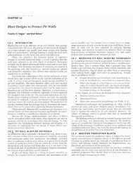
The blasting results using non-electric system<br />
(fragmentation, vibration control) are much more positive.<br />
Before the non-electric system was introduced,<br />
the only way to perform a non-electric blast was using<br />
a detonating cord. The method is now almost abandoned<br />
as it has numerous undesired side effects. When<br />
initiating a blast using a detonating cord, the blast hole<br />
is opened from the top which creates excessive fly rock<br />
because the stemming is destroyed as the detonation<br />
passes through it. As a result, the energy created by<br />
detonation is used less effectively. In addition, when<br />
used to initiate relatively insensitive explosives such as<br />
ANFO and certain emulsion explosives, the detonating<br />
cord can cause dead-pressing of the explosive. Further<br />
disadvantages of using detonating cord for initiation<br />
include excessive noise. Using of non-electric system<br />
enables to initiate the blast hole from the bottom (see<br />
figure 0-1) which ensures better use of the blast energy.<br />
Fig. 0-2<br />
S H O C K S T A R / I N D E T S H O C K<br />
i<br />
3
4<br />
1<br />
2<br />
3<br />
4<br />
1. COMPONENTS OF NON-ELECTRIC INITIATION SYSTEM AND THEIR FUNCTION<br />
<strong>Austin</strong> Shock tube and all <strong>Austin</strong> <strong>Detonator</strong> products<br />
using <strong>Austin</strong> Shock tube can be initiated by regular<br />
electric or non-electric detonator, detonating cord,<br />
plain detonator, SHOCKSTAR BUNCH CONNECTOR,<br />
SHOCKSTAR SURFACE, and proper blasting machine<br />
(from an open end of the shock tube only).<br />
SHOCKSTAR SURFACE<br />
SHOCKSTAR SURFACE is a millisecond delay<br />
detonator enclosed in a color coded plastic block.<br />
This detonator has a smaller base charge designed<br />
for initiation of shock tube only.<br />
INDETSHOCK MS 25/50 INDETSHOCK TS<br />
These are in-hole detonators with millisecond<br />
delay (steps 25 ms and 50 ms) and long period delay<br />
detonators used for initiation of explosive in a hole.<br />
INDETSHOCK MS 25/50 is used for surface applications,<br />
INDETSHOCK TS in underground applications.<br />
These detonators can be initiated by means mentioned<br />
at the top of this section. For initiation by detonating<br />
cord they can be fitted with a T-connector.<br />
SHOCKSTAR BUNCH CONNECTOR<br />
The base charge of these detonators is designed<br />
for initiation of a 5-6 g/m PETN detonating cord,<br />
which is attached to it. The detonator is enclosed in<br />
a plastic block and the detonating cord is inserted in<br />
the plastic block. The detonator is used for initiation<br />
of up to 20 shock tubes tied in a bunch, which is<br />
closely described later in this manual. The detonator<br />
is mostly used in underground applications.<br />
SHOCKSTAR DUAL DELAY<br />
SHOCKSTAR DUAL DELAY is composed of<br />
SHOCKSTAR SURFACE and an in-hole detonator<br />
INDETSHOCK MS 25/50. Dual Delay detonator is<br />
used in the same way as the two detonators of which<br />
it is composed. The benefits of Dual Delay detonators<br />
include faster handling, easier connections and<br />
decrease of excessive shock tube during connecting,<br />
thus making it easier to overview the connections<br />
on the blast site.<br />
S H O C K S T A R / I N D E T S H O C K<br />
Fig. 1-1<br />
Fig. 1-2<br />
Fig. 1-3<br />
Fig. 1-4
i<br />
2. PRINCIPLE OF INITIATION OF A NON-ELECTRIC SYSTEM<br />
The basic principle of initiation is transferring<br />
initiation from surface connector to a detonator in a<br />
hole and to another surface connector.<br />
The figure 2-1 shows properly timed blasting<br />
pattern - the holes are initiated well before the rock<br />
starts moving.<br />
Fig. 2-1<br />
NOTICE<br />
For a successful blast it is necessary that a<br />
hole is initiated well before the initiation network<br />
is destroyed by the blast itself. This is<br />
ensured by suitably designed blast pattern.<br />
S H O C K S T A R / I N D E T S H O C K 5
6<br />
1<br />
3. CONSTRUCTION AND TECHNICAL DESCRIPTION OF NONELECTRIC DETONATORS<br />
SHOCKSTAR SURFACE<br />
(with millisecond delay)<br />
The new SHOCKSTAR SURFACE is a highly user-<br />
-friendly product bringing substantial time-savings<br />
when connecting initiation network. The design of<br />
the connector virtually eliminates the shrapnel cut-off<br />
concerns, and makes easier the composition of initiation<br />
network. The connector has 9 delay stages. The<br />
initiation strength of SHOCKSTAR SURFACE detonators<br />
is 0,11 g PETN. The detonators are composed of an<br />
aluminum shell containing a base charge and a highly<br />
accurate delay composition system, anti-static rubber<br />
plug, shock-tube fitted with a stopper and a delay tag<br />
(see fig. 3-1). The stopper prevents the tube end from<br />
coming out of the connector block. The detonator is<br />
enclosed in a color coded plastic block. These units are<br />
specially designed for surface delay patterns and are<br />
used to initiate INDETSHOCK MS 25/50 and TS, and<br />
to relay the initiation impulse to the next SHOCKSTAR<br />
SURFACE connector(s) in sequence.<br />
Fig. 3-1<br />
stopper<br />
delay tag<br />
NOTICE<br />
The SHOCKSTAR SURFACE is an assembly<br />
composed of two main parts: a plastic connector<br />
and a small detonator with a shock tube<br />
attached. The plastic connector houses the<br />
detonator. The entire unit is assembled by the<br />
manufacturer and makes a permanent assemb-<br />
ly. The disassembly may result in damage to the<br />
unit. Surface detonators must not be used to<br />
initiate explosives and detonating cord!<br />
S H O C K S T A R / I N D E T S H O C K<br />
TECHNICAL DATA<br />
<strong>Detonator</strong> Shell<br />
Material: Aluminum<br />
Outside diameter: 7,65 mm max.<br />
Length: 62 mm<br />
Marking: nominal delay time<br />
Connector<br />
Material: PE<br />
Body color: as per nominal delay<br />
Plug color as per nominal delay<br />
Anti-static sealing plug<br />
Material: conductive rubber<br />
Color: black<br />
Shock-tube<br />
Material: Surlyn / PE<br />
Base length: 2,4 + x x 0,6 m<br />
(x = 0, 1, 2, 3 ... 41)<br />
Color: yellow<br />
Detonation velocity: 2000 m/s<br />
Marking: delay tag<br />
production series number<br />
detonator type<br />
nominal delay time<br />
shock-tube length<br />
traceability code<br />
Nominal delay time<br />
(ms)<br />
0<br />
9<br />
17<br />
25<br />
33<br />
42<br />
67<br />
100<br />
200<br />
NOMINAL DELAYS<br />
SHOCKSTAR SURFACE<br />
Color<br />
green<br />
brown<br />
yellow<br />
red<br />
grey<br />
white<br />
blue<br />
black<br />
orange<br />
i
2<br />
i<br />
IN-HOLE DETONATORS<br />
INDETSHOCK MS 25/50<br />
(with 25 or 50 ms delay interval)<br />
INDETSHOCK TS<br />
(with 50, 100, 200 and 500 ms delay interval)<br />
These detonators have initiating strength No. 12<br />
(0,72 g PETN). The detonators are made of aluminum<br />
shell containing the primary charge, delay composition<br />
system, shock-tube, antistatic sealing plug, stopper<br />
and delay tag.<br />
The detonators can be fitted with a T-connector<br />
(see figure 3-3 and 3-4) for detonating cord compatibility,<br />
and they are used to initiate primers (boosters)<br />
or directly commercial explosives.<br />
The T-connectors cannot be supplied separately<br />
for later application on the detonator shock tube. They<br />
can be applied only during production in the factory.<br />
Fig. 3-2c T-connector<br />
TECHNICAL DATA<br />
<strong>Detonator</strong> Shell<br />
Material: Aluminum<br />
Outside diameter: 7,65 mm max.<br />
Length: 58 to 93 mm<br />
Marking: nominal delay time<br />
letter „V“ at the shell<br />
bottom<br />
Antistatic Sealing Plug<br />
Material: conductive rubber<br />
Color: black<br />
Shock-Tube<br />
Material: Surlyn / PE<br />
Base lehgth: 2,4 + x x 0,6 m<br />
(x = 0, 1, 2, 3 ... 41)<br />
Color: yellow<br />
Detonation velocity: 2000 m/s<br />
Marking: delay tag<br />
production series number<br />
detonator type<br />
nominal delay time/<br />
delay number<br />
shock-tube length<br />
traceability code<br />
Fig. 3-2a INDETSHOCK MS 25/50<br />
Fig. 3-2b INDETSHOCK TS<br />
Fig. 3-3<br />
Fig. 3-4<br />
T-connector<br />
T-connector<br />
delay tag<br />
S H O C K S T A R / I N D E T S H O C K 7
8<br />
tab. 2<br />
Delay<br />
number<br />
0<br />
1<br />
2<br />
3<br />
4<br />
5<br />
6<br />
7<br />
8<br />
9<br />
10<br />
11<br />
12<br />
13<br />
14<br />
15<br />
16<br />
17<br />
18<br />
19<br />
20<br />
21<br />
22<br />
23<br />
24<br />
25<br />
26<br />
27<br />
28<br />
29<br />
30<br />
S H O C K S T A R / I N D E T S H O C K<br />
NONELECTRIC DETONATORS DELAY TIMES<br />
MS 25/50 TS<br />
Nominal delay<br />
time (ms)<br />
0<br />
25<br />
50<br />
75<br />
100<br />
125<br />
150<br />
175<br />
200<br />
225<br />
250<br />
275<br />
300<br />
325<br />
350<br />
375<br />
400<br />
425<br />
450<br />
475<br />
500<br />
550<br />
600<br />
650<br />
700<br />
750<br />
800<br />
850<br />
900<br />
950<br />
1000<br />
Delay<br />
interval (ms)<br />
25<br />
25<br />
25<br />
25<br />
25<br />
25<br />
25<br />
25<br />
25<br />
25<br />
25<br />
25<br />
25<br />
25<br />
25<br />
25<br />
25<br />
25<br />
25<br />
25<br />
50<br />
50<br />
50<br />
50<br />
50<br />
50<br />
50<br />
50<br />
50<br />
50<br />
50<br />
Delay<br />
number<br />
0<br />
1<br />
1 1/2<br />
2<br />
2 1/2<br />
3<br />
3 1/2<br />
4<br />
4 1/2<br />
5<br />
5 1/2<br />
6<br />
6 1/2<br />
7<br />
7 1/2<br />
8<br />
8 1/2<br />
9<br />
9 1/2<br />
10<br />
11<br />
12<br />
14<br />
16<br />
18<br />
20<br />
25<br />
30<br />
35<br />
40<br />
45<br />
50<br />
55<br />
60<br />
65<br />
70<br />
75<br />
80<br />
85<br />
90<br />
Nominal delay<br />
time (ms)<br />
25<br />
100<br />
150<br />
200<br />
250<br />
300<br />
350<br />
400<br />
450<br />
500<br />
550<br />
600<br />
650<br />
700<br />
750<br />
800<br />
850<br />
900<br />
950<br />
1000<br />
1100<br />
1200<br />
1400<br />
1600<br />
1800<br />
2000<br />
2500<br />
3000<br />
3500<br />
4000<br />
4500<br />
5000<br />
5500<br />
6000<br />
6500<br />
7000<br />
7500<br />
8000<br />
8500<br />
9000<br />
Delay<br />
interval (ms)<br />
-<br />
100<br />
50<br />
50<br />
50<br />
50<br />
50<br />
50<br />
50<br />
50<br />
50<br />
50<br />
50<br />
50<br />
50<br />
50<br />
50<br />
50<br />
50<br />
50<br />
100<br />
100<br />
200<br />
200<br />
200<br />
200<br />
500<br />
500<br />
500<br />
500<br />
500<br />
500<br />
500<br />
500<br />
500<br />
500<br />
500<br />
500<br />
500<br />
500
3<br />
i<br />
4<br />
SHOCKSTAR BUNCH CONNECTOR<br />
This detonator is fitted with a Bunch Connector<br />
with a 5 g/m PETN detonating cord. The detonator<br />
base charge of 0,16 g PETN is designed to initiate<br />
the attached detonating cord. SHOCKSTAR BUNCH<br />
CONNECTOR is available in the following delays: 0,<br />
9, 17, 25, 33, 42, 67, 100, 200 ms.<br />
Fig. 3-5<br />
TECHNICAL DATA<br />
<strong>Detonator</strong> Shell<br />
Material: Aluminum<br />
Outside diameter: 7,65 mm max.<br />
Length: 54 mm<br />
Marking: nominal delay time<br />
Connector<br />
Material: PE<br />
Body color: as per nominal delay<br />
Plug color: as per nominal delay<br />
Anti-static sealing plug<br />
Material: conductive rubber<br />
Color: black<br />
Shock-tube<br />
Material: Surlyn / PE<br />
Base length: 2,4 m min.<br />
Color: red<br />
<strong>Detonator</strong> velocity: 2000 m/s<br />
Marking: delay tag<br />
production series number<br />
detonator type<br />
nominal delay time<br />
shock-tube length<br />
traceability code<br />
SHOCKSTAR DUAL DELAY DETONATOR<br />
SHOCKSTAR DUAL DELAY detonator is a combination<br />
of SHOCKSTAR SURFACE (nominal delays<br />
0, 17, 25, 42, 67, 100, 200 ms) and INDETSHOCK<br />
MS 25/50 or INDETSHOCK TS (nominal delays 350,<br />
475, 500, 800, 9000 ms). DUAL DELAY detonators<br />
are used in surface bench blasts and underground<br />
blasts. Like all nonelectric detonators, they cannot<br />
be used in gassy coalmines underground. Their use<br />
results in smaller number of detonators needed for<br />
one blast. Use of SHOCKSTAR DUAL DELAY detonators<br />
brings the following advantage:<br />
reduced handling and storage requirements<br />
faster Composition of initiation network<br />
reduced number of connections between units<br />
easier and more reliable visual inspection of connection<br />
Fig. 3-6 Non-electric detonators SHOCKSTAR Dual Delay<br />
TECHNICAL DATA<br />
Shock-tube<br />
Material: Surlyn / PE<br />
Base Length: 2,4 + x x 0,6 m<br />
(x = 0, 1, 2, 3 ... 41)<br />
Color: yellow<br />
Detonation velocity: 2000 m/s<br />
Marking: delay tag<br />
NOMINAL DELAYS<br />
SHOCKSTAR DUAL DELAY<br />
SHOCKSTAR SURFACE INDETSHOCK MS 25/50<br />
INDETSHOCK TS<br />
0 ms<br />
800 ms<br />
17 ms<br />
475, 500 ms<br />
25 ms 350, 475, 500 ms<br />
42 ms 475, 500, 9000 ms<br />
67 ms 475, 500, 9000 ms<br />
100 ms<br />
9000 ms<br />
200 ms<br />
tab. 3<br />
9000 ms<br />
S H O C K S T A R / I N D E T S H O C K 9<br />
i
10<br />
Bench blast design using SHOCKSTAR DUAL DELAY, SHOCKSTAR SURFACE and INDETSHOCK MS 25/50<br />
Shock-tube color<br />
• SHOCKSTAR SURFACE<br />
• SHOCKSTAR DUAL DELAY<br />
INDETSHOCK MS 25/50<br />
•<br />
Fig. 3-7<br />
4. PRACTICAL USE OF NONELECTRIC DETONATORS AND THE BENEFITS OF USE<br />
SHOCKSTAR/INDETSHOCK detonators are used<br />
for initiation of commercial explosives used for blasting<br />
both above and underground.<br />
WARNING<br />
Non-electric detonators SHOCKSTAR/INDET-<br />
SHOCK must not be used in worksites with<br />
coal dust and methane atmosphere.<br />
Conditions of use:<br />
temperatures ranging from -30 °C to +60 °C<br />
in water pressure of max 0,3 MPa / 7 days<br />
Advantages:<br />
fit for use in wet conditions and under water<br />
high variability of timing<br />
highly safe product<br />
reduction of vibration during blast<br />
S H O C K S T A R / I N D E T S H O C K<br />
Instruction for use of SHOCKSTAR SURFACE 1<br />
CONNECTING<br />
Prepare a loop a shown in the picture.<br />
When connecting the tube in the connector, always<br />
pull the tube in the direction towards the middle<br />
of the connector block cavity for tubes. This method<br />
puts the least demand on strength needed for making<br />
a connection.
CAUTION<br />
During connection make sure that the tubes are<br />
properly insterted into the connector block and that<br />
they are not crossed inside the connector block. Each<br />
side of the connector block can hold up to 4 tubes,<br />
the total capacity of the block is 8 tubes.<br />
If needed, it is possible to lock the tubes in to secure<br />
the connection. The connector is however fully<br />
functional in both locked and unlocked position provided<br />
the tubes are inserted properly.<br />
CAUTION<br />
Do not use any version of „double hooking“ as a safety<br />
precaution against preventing the shock tube from<br />
slipping out of the Shockstar connector. For this purpose,<br />
every shock tube is fitted with a plastic sleeve at its<br />
end. Double hooking is a nonstandard connection not<br />
compliant with the design of the Shockstar product,<br />
and it may result in improper function.<br />
DISCONNECTING<br />
Hold the loop as when connecting and pull the tube<br />
out from the connector block.<br />
obr. 4-5<br />
Application INDETSHOCK MS 25/50 detonators<br />
in open pit blasting operations<br />
The explosive in the drill hole is initiated by two<br />
in-hole detonators INDETSHOCK MS 25/50. One<br />
detonator is located at the bottom (lower) part of<br />
the drill hole. The other detonator is positioned<br />
at the top (upper) part of the drill hole, under the<br />
stemming. Normally, a 475 ms detonator is used at<br />
the bottom and a 500 ms detonator at the top of<br />
the drill hole. With drill holes longer than 30 m, a<br />
450 ms detonator is recommended for use at the<br />
bottom of the hole.<br />
Fig. 4-6<br />
S H O C K S T A R / I N D E T S H O C K 11<br />
C<br />
2
12<br />
<strong>Detonator</strong>s should be positioned such, that the<br />
detonator bottom is directed towards the longer part<br />
of the explosive column. The lower detonator should<br />
point upwards and the upper detonator should point<br />
downwards. The in-hole detonators are initiated by<br />
SHOCKSTAR SURFACE. The initiation of explosive in<br />
this fashion brings the most effective consumption<br />
of energy released during explosion.<br />
The detonation velocity of the shock-tube impulse<br />
is 2000 m/s. The shock-tube then presents a delay<br />
of 0,5 ms/m of tube. The delay caused by shock-tube<br />
therefore needs to be taken into consideration when<br />
designing the blasting patterns. Where detonators of<br />
identical nominal delay time in drill hole are used,<br />
the explosive in the drill hole is initiated from the<br />
top causing less effective consumption of energy<br />
released during explosion.<br />
PRECAUTIONS<br />
The detonator bottom must be directed<br />
towards the longer part of explosive charge<br />
column.<br />
All in-hole priming assemblies (detonator<br />
+ primer) should have identical orientation.<br />
When designing a blast pattern, a shock<br />
tube added delay time of 1 ms / 2 meters<br />
must be taken into consideration.<br />
With drill holes longer than 10 m, two priming<br />
assemblies should always be used. If<br />
the drill hole is shorter than 10 m, only one<br />
priming assembly may be used provided<br />
the drill hole walls are smooth and the risk<br />
of interruption of explosive column during<br />
charging is eliminated.<br />
The minimal length of the shock tube coming<br />
out of priming assembly and out of the<br />
drill hole is 0,6 m.<br />
Make sure that connector-to-connector distances<br />
are identical in aII connections.<br />
Do not cut short the shock tube. Water or<br />
humidity may make the shock tube non-functional.<br />
OnIy cut the shock tube immediately<br />
prior the blast for testing the blasting machine<br />
and for the blast itself.<br />
S H O C K S T A R / I N D E T S H O C K<br />
SHOCKSTAR BUNCH CONNECTOR assembly 3<br />
PRECAUTIONS<br />
Ensure that there is sufficient shock tube<br />
to make up a bunch.<br />
Ensure that the detonating cords in SHOCK-<br />
STAR BUNCH CONNECTORS are kept at Ieast<br />
20 cm away from other shock tubes, which<br />
are not part of the bunch.<br />
Do not fit more than 20 tubes in a bunch.<br />
Fig. 4-7<br />
Fig. 4-8
4<br />
A<br />
Notes on designing blasting patterns<br />
Gradual initiation of blastholes<br />
Very frequently, the blast pattern is designed<br />
such that rows are initiated from one side as shown<br />
in figure 4-9. This method brings time savings during<br />
connecting the blast pattern. The method has dis-<br />
advantage however. If initiation is stopped in a row,<br />
the entire initiation process is not stopped but continues.<br />
Problem which result from an undetonated row<br />
in an otherwise finished blast could be costly.<br />
Fig. 4-9<br />
<strong>Austin</strong> <strong>Detonator</strong>, on the other hand, recommends<br />
to design the blasting pattern in such a way,<br />
that if in one element, the initiation is stopped,<br />
entire initiation process is stopped and only properly<br />
initiated holes blast. This method is shown in figure<br />
4-10 and is considered by blasters as an important<br />
preventive measure which could be taken to avoid<br />
problems with removing misfires.<br />
Fig. 4-10 Three-row one-side-initiated bench blast delay pattern<br />
Coupled initiation blasting pattern<br />
Another means of ensuring a successful blast is a<br />
blasting pattern is using initiation of a blast hole<br />
from two sources of initiation (two connectors). This<br />
blasting pattern can be used when two detonators<br />
are used in a hole. The initiation impulse is brought<br />
to the hole from two sources, bringing extra ensuring<br />
feature to blasting operations.<br />
Fig. 4-11 Blasting pattern with coupled initiation<br />
The bench blasting examples<br />
Three-row one-side-initiated bench blast<br />
Fig. 4-10 - the initiation point is marked as START.<br />
All drill holes are charged with detonators of identical<br />
nominal delay time. SHOCKSTAR SURFACE provide<br />
individual drill hole timing. The diagram shows a<br />
pattern with delay times of 25 ms between holes in<br />
the first row and last two holes in the second and<br />
third row. The delay time between rows is 42 ms.<br />
The numbers inside the circles show the firing time<br />
of the SHOCKSTAR SURFACE in a given drill hole.<br />
The value is a sum of SHOCKSTAR SURFACE nominal<br />
delay and delays preceding the given point of initiation.<br />
The explosive charge in the drill hole is initiated<br />
475 ms after the arrival of initiation impulse. Arrows<br />
indicate the direction of detonator connections and<br />
the detonation wave travel direction. The diagram<br />
also shows the direction of rock movement.<br />
S H O C K S T A R / I N D E T S H O C K<br />
B<br />
C<br />
13
14<br />
PRECAUTION<br />
<strong>Detonator</strong> connections should be made only<br />
in one direction, i.e., either from the first<br />
or the last delay in sequence.<br />
The connector is designed to reliably initiate<br />
up to 8 shock tubes.<br />
It is highly recommended that the shocktubes<br />
between drill holes are not subject<br />
to mechanical stress (tension).<br />
A minimum of 0,6 m of additional shocktube<br />
per detonator should be included<br />
when considering the required length of<br />
shock tube.<br />
After all drill holes are connected, a careful<br />
visual inspection of all connections must be<br />
made. After the inspection, no one should<br />
Fig. 4-12 Three-row one-side-initiated bench blast delay pattern (including snake holes)<br />
Fig. 4-13 Three-row center-initiated bench blast delay pattern (including snake holes)<br />
S H O C K S T A R / I N D E T S H O C K<br />
be allowed to enter the blast area.<br />
The system can be initiated by special blasting<br />
machines SUREFIRE and MICKO 1 (fig.<br />
4-18 and 4-19). It is also possible to use<br />
an electric detonator or fuse cap fastened<br />
to shock tube by a tape. The bottom of the<br />
initiating detonator must point in the direction<br />
of the blast pattern initiation.<br />
Three-row one-side-initiated bench blast inclu-<br />
-ding snake holes<br />
Fig. 4-12 - A situation similar to Fig. 4-10 but with<br />
snake holes connected using SHOCKSTAR SURFACE<br />
42 ms, 34m shock tube length. The delay between<br />
holes in the first row is 17 ms, the delay between<br />
rows is 25 ms. The snake holes are initiated by
5<br />
INDETSHOCK MS 25 / 50,475 ms nominal delay and<br />
a primer. The detonator/primer assembly is located<br />
in the front part of the hole, towards the stemming.<br />
The snake holes are also initiated at START point. The<br />
precautions and instruction valid for blasts in figures<br />
4-6 and 4-10 should be applied also for this blast.<br />
Three-row center-initiated bench blast including<br />
snake holes<br />
Fig. 4-13 - The picture shows the same blasting<br />
pattern as in figure 4-12 except that the initiation<br />
start is in the center of the first row and the delays<br />
between holes in the first row are a combination of<br />
17 and 42 ms. The delays between snake holes<br />
are a combination of 9, 17, 25 and 42 ms. Rock<br />
movement is to the center of the field.<br />
Central-initiated pull shot<br />
Fig. 4-14 - This pattern is one of many which are<br />
possible for this type of blasting operation. The<br />
system is initiated gradually from the center of the<br />
pattern. The precautions and instruction valid for<br />
blasts in Figures 4-6 and 4-10 should be applied<br />
also for this blast. The initiation pattern should be<br />
connected from the center of the field - nominal delay<br />
0 ms. The rock movement in this case is limited only<br />
to pile up and raise.<br />
Fig. 4-14<br />
Instruction for removal of misfires<br />
The procedure for removal of misfires is the<br />
same as with other types of initiations. The difference<br />
using INDETSHOCK/SHOCKSTAR non-electric<br />
initiation system is that it is possible to easily identify<br />
whether an initiation impulse passed through the<br />
misfired detonator. Simply cut off 20-30 cm of the<br />
shock-tube. Place the shock-tube vertically against<br />
a pad and blow through the shock tube. If there<br />
was no initiation impulse passing through the shock<br />
tube, you will see a white powdery explosive charge<br />
coming out of the shock tube onto the pad. When<br />
cutting off the shock-tube, use only knife. Never cut<br />
the shock-tube by scissors!<br />
Using SHOCKSTAR detonators in underground<br />
blasting applications<br />
The advantage brought by non-electric initiation<br />
system INDETSHOCK/ SHOCKSTAR can be conveniently<br />
used for tunneling and underground blasting<br />
as well. For these applications INDETSHOCK TS has<br />
been especially designed. Normally, the detonator<br />
is inserted into a booster or an explosive charge to<br />
form a primer for the hole.<br />
Fig. 4-15 Tunnel blast pattern<br />
The detonator bottom should always point towards<br />
the longer part of the explosive charge column to<br />
ensure efficient initiation. The tubes coming out of<br />
the holes are bound together in bunches. A bunch<br />
can be made of maximum of 20 tubes. Each bunch<br />
should be securely taped with electrical tape at two<br />
points 30 cm apart (see fig. 4-7). Each bunch of<br />
tubes, the section enclosed by electrical tapes, is then<br />
fed through a BUNCH CONNECTOR. In this way, all the<br />
S H O C K S T A R / I N D E T S H O C K<br />
6<br />
15
7<br />
16<br />
shock-tubes in a blast are assembled into bunches<br />
and connected to BUNCH CONNECTORS. The number<br />
of BUNCH CONNECTORS is determined by the number<br />
of holes to be fired. The shock-tubes coming out of<br />
the detonators in holes are connected to SHOCKSTAR<br />
SURFACE, 0 ms (start-line) or BUNCH CONNECTOR,<br />
depending on the number of shock-tubes. As shown<br />
in figure 4-15, there are 65 charged drillholes. Shock-<br />
-tubes coming out of the detonators inside the holes,<br />
are fed into 4 BUNCH CONNECTOR units. The tubes<br />
coming out of the 4 BUNCH CONNECTOR units are<br />
connected into a SHOCKSTAR SURFACE (start-line)<br />
of required shock-tube length.<br />
Application of INDETSHOCK/SHOCKSTAR detonators<br />
for demolition operations<br />
The advantage brought by non-electric initiation<br />
system INDETSHOCK / SHOCKSTAR can be conveniently<br />
used for demolition operations, especially<br />
in environments where foreign sources of electricity<br />
(stray currents, radio frequency, or electrostatic energy)<br />
may be present and use of electric detonators<br />
would present a hazard.<br />
A very advantageous solution is a combination<br />
of detonating cord and non-electric detonator fitted<br />
with a T-connector. T-connector („J“ hook) provides a<br />
quick and reliable connection to detonating cord for<br />
initiation of detonators. The detonating cord itself is<br />
then initiated by a regular electric detonator. One of<br />
the advantages of using detonating cord/T-connector<br />
combination is easy and fast connecting resulting in<br />
increased safety of the whole blast work.<br />
Fig. 4-16 Demolition of concrete beds<br />
S H O C K S T A R / I N D E T S H O C K<br />
Initiation of non-electric system<br />
The shock-tube of nonelectric detonators can be<br />
initiated by means of a regular electric detonator attached<br />
to the tube by a tape, or by means of a spark<br />
blasting machine SUREFIRE, or by means of blasting<br />
machine MICKO 1.<br />
<br />
Fig. 4-17 Initiation by means of an electric detonator. Ensure<br />
that the detonator bottom is pointing in the direction opposite<br />
to the Startline signal propagation and opposite to the initation<br />
network area.<br />
Fig. 4-18 MICKO - 1, blasting machine for initiation of electric<br />
and nonelectric detonators<br />
Fig. 4-19: Blasting machine SUREFIRE<br />
Fig. 4-20<br />
detonator shell bottom<br />
tube signal direction / initiation network area<br />
<br />
48
9<br />
1<br />
Removal of nonelectric initiation system remains after use<br />
Non-active (fired) remains of shock-tubes are<br />
collected in a designated area and handed over to<br />
companies licensed for removal of industrial waste,<br />
catalogue No. 15 01 02, category O (plastic pa-<br />
Packaging<br />
Assembled non-electric detonators are packed<br />
into fibreboard cartons. Inside the cartons the detonators<br />
are packed in vacuum-sealed plastic bags. The<br />
quantity per carton is determined by the shock-tube<br />
5. PACKAGE, STORAGE AND ORDERING<br />
Fig. 5-1 Outer carton label Fig. 5-2 <strong>Detonator</strong> tag<br />
ckages). Metal parts of detonators (shrapnels) are<br />
collected in a designated area and handed over to<br />
companies licensed for use of industrial waste, catalogue<br />
No. 17 04 07, category O (various metals).<br />
length (see packaging in <strong>Austin</strong> <strong>Detonator</strong> Product<br />
Literature CD). The cartons are tested and certified<br />
and are in strict conformity with the International<br />
Agreement of Road, Train, Sea and Air Transport<br />
(ADR, RID, IMDG, IATA). The cartons and are marked<br />
with the appropriate ® code.<br />
S H O C K S T A R / I N D E T S H O C K<br />
17
2<br />
3<br />
18<br />
Shelf life and storage conditions<br />
a) For nonelectric detonators packed in original unopened<br />
aluminum foil bags, the shelf life is 2 years,<br />
if stored in temperatures between -30 and +40°C.<br />
After opening the foil bag, the detonators must be<br />
used within 3 months.<br />
b) For nonelectric detonators packed in original unopened<br />
plastic bags, the shelf life is 2 years if<br />
stored in temperatures between -30 and +40°C<br />
and relative humidity not exceeding 65%. After<br />
opening the plastic bag, the detonators must be<br />
used within 3 months.<br />
c) For nonelectric detonators packed in paper boxes<br />
without aluminium foil bags, the shelf life is 3<br />
months.<br />
The storage place should be clean, well ventilated,<br />
dry, protected from fire, and securely locked when<br />
not in use.<br />
Storage and transportation classification<br />
The detonators are classified for transport as follows:<br />
Standard packaging<br />
1.1B, UN 0360<br />
INDETSHOCK MS 25/50, INDETSHOCK TS, SHOCK-<br />
STAR DUAL DELAY, SHOCKSTAR BUNCH CONNECTOR<br />
(with detonating cord)<br />
1.4S, UN 0500<br />
SHOCKSTAR SURFACE, SHOCKSTAR BUNCH CON-<br />
NECTOR (without detonating cord)<br />
Special packaging (at special request)<br />
1.4S UN 0500; 1.4B, UN 0361<br />
Available for all products except SHOCKSTAR SUR-<br />
FACE and SHOCKSTAR BUNCH CONNECTOR (without<br />
detonating cord)<br />
This classification also relates to transportation<br />
regulations as per RID, ADR, ADN and IATA DGR.<br />
The detonators should not be subject to temperatures<br />
higher than 50°C and should be protected from<br />
direct sunlight.<br />
S H O C K S T A R / I N D E T S H O C K<br />
AVALIABLE SHOCK TUBE LENGHTS<br />
loop configuration<br />
All detonators except DUAL DELAY:<br />
3 - 10,2 m - step of 0,6 m<br />
12 m and more - step of 3 m<br />
DUAL DELAY:<br />
6 m and more - step of 3 m<br />
spool configuration<br />
30 m and more - step of 3 m<br />
Placing orders 4<br />
An example of an order:<br />
Type/nominal delay time/shock-tube length:<br />
INDETSHOCK MS 25/50 MS 475 ms/3,6 m<br />
without T - connector<br />
INDETSHOCK MS 25/50 MS T 500 ms/6 m<br />
with T - connector<br />
INDETSHOCK TS TS 300 ms/3 m<br />
without T - connector<br />
INDETSHOCK TS TS T 200 ms/4,2 m<br />
with T - connector 9 ms/3,6 m<br />
SHOCKSTAR SURFACE SHOCKSTAR SURFACE<br />
17 ms/4.8 m<br />
SHOCKSTAR BUNCH BUNCH CONNECTOR<br />
CONNECTOR<br />
SHOCKSTAR DUAL DELAY DUAL DELAY<br />
17-475 ms/18 m
7. NOTES<br />
Declaimer of Warranties and Limitation of Liabilities.<br />
Products described in this brochure are sold by <strong>Austin</strong> <strong>Detonator</strong> s.r.o. without warranty; express, implied, or statutory or as MERCHANTABILITY,<br />
except as expressly stated in <strong>Austin</strong> <strong>Detonator</strong> s.r.o. straight bill of lading. Under no circumstances shall seller be liable for damages for loss<br />
of anticipated profits, consequential damages or incidental damages.<br />
S H O C K S T A R / I N D E T S H O C K 19
<strong>Austin</strong> <strong>Detonator</strong> s.r.o.<br />
Jasenice 712, 755 01 Vsetín, Czech Republic<br />
tel.: +420 571 404 021, fax: +420 571 431 926<br />
e-mail: marketing.info@austin.cz<br />
w w w . a u s t i n . c z<br />
© <strong>Austin</strong> <strong>Detonator</strong> s.r.o. | v. 290212