Intro_to_Mining - Mining and Blasting
Intro_to_Mining - Mining and Blasting
Intro_to_Mining - Mining and Blasting

You also want an ePaper? Increase the reach of your titles
YUMPU automatically turns print PDFs into web optimized ePapers that Google loves.
Unit 16<br />
Mine Development
In this unit, you will learn how a Mine is<br />
developed for production, how a shaft is sunk,<br />
how lateral headings <strong>and</strong> raises are mined.
After completing this unit, you should be able <strong>to</strong>:<br />
• Explain the methods of "opening a deposit"<br />
• Lists the steps of shaft sinking<br />
• Lists the type of shafts<br />
• Big Hole Drilling<br />
• Ground Freezing<br />
• Shaft Linings<br />
• Lateral Development & Ramps<br />
• Track versus Trackless<br />
• Design <strong>and</strong> function of Lateral Headings<br />
• Laser Control<br />
• Raises
Mine Development<br />
When a promising mineral deposit has been<br />
found, production is the next thing <strong>to</strong><br />
consider. All mines require considerable<br />
development before actual ore production can<br />
begin.<br />
The orebody is "opened up" by excavation. In<br />
opening a mine, a small mining company<br />
usually digs any ore that is showing. The<br />
revenue from the sale of the ore keeps the<br />
venture going <strong>and</strong> finances further<br />
development. After the ore body has been<br />
delineated <strong>and</strong> defined, a company may make<br />
several feasibility studies <strong>to</strong> determine the<br />
best way <strong>to</strong> mine the ore.
Opening a deposit<br />
A) Open Pit<br />
Stripping the overburden is<br />
always a problem. The wider <strong>and</strong><br />
richer the vein the deeper the pit.<br />
The availability <strong>and</strong> production<br />
capability of surface equipment<br />
makes open-pit mining a very<br />
attractive choice.
B) Drift <strong>Mining</strong><br />
If the ore vein is narrow <strong>and</strong> the<br />
terrain is favourable, a drift or<br />
adit on the vein is often used.<br />
The drift is mined in<strong>to</strong> the vein<br />
at an almost flat elevation.
C) Inclined Shaft<br />
In flat terrain, a shaft is almost<br />
always required in a narrow<br />
vein. The shaft runs parallel <strong>to</strong><br />
the orebody in the footwall for<br />
stability. Normally the footwall<br />
is used for ground stability.<br />
Cross-cuts or levels run out <strong>to</strong><br />
intersect the ore vein.
C) Crosscuts <strong>to</strong> Veins<br />
In steep mountainous terrain,<br />
crosscuts <strong>to</strong> veins can be<br />
used.<br />
Crosscuts have the advantage<br />
of draining water <strong>and</strong> hauling<br />
ore on a near level horizon.
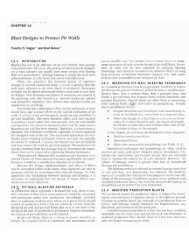
D) Vertical Shaft <strong>Mining</strong><br />
Many mines use vertical shafts<br />
for narrow veins.<br />
Location 1 is preferred over 2<br />
<strong>and</strong> 3 but may require<br />
increasingly longer cross-cuts<br />
<strong>to</strong> reach the orebody as the<br />
depth increases.
E) Ramps<br />
With the increased uses of diesel powered LHD<br />
units, ramps are becoming popular ways of<br />
developing dipping deposits.
Shaft Sinking<br />
Of all the headings driven in hard rock<br />
mines, shafts are the most costly <strong>and</strong><br />
time consuming. Moreover, the shaft<br />
sinking procedure is intricate <strong>and</strong><br />
arduous. While a few shafts are<br />
advanced by big-hole drilling<br />
methods, the great majority use the<br />
traditional "drill <strong>and</strong> blast" cycle.<br />
Shafts for smaller mines have<br />
traditionally been sunk rectangular<br />
<strong>and</strong> relied on timber for support.<br />
Larger mines have typically employed<br />
circular shafts lined with concrete<br />
poured in place as the sinking<br />
advances.
On the surface of an underground mine, a<br />
collar is required for a shaft or raise entry,<br />
while a portal refers <strong>to</strong> the entrance for an<br />
adit, decline, or ramp.<br />
Collar<br />
Collars are also required for ventilation<br />
shafts, service shafts, <strong>and</strong> for all raises that<br />
reach surface. Constructing collars in a<br />
rock outcrop or in shallow overburden is<br />
relatively straightforward; however, if the<br />
soil overburden is deep <strong>and</strong> especially if it<br />
is water bearing, collar construction can<br />
become a major project. Shaft <strong>and</strong> raise<br />
collars are normally lined with concrete.
Portals<br />
Portals may be left open <strong>to</strong> the<br />
elements in tropical zones;<br />
however, the entrance is often<br />
enclosed with a weather-tight<br />
structure in temperate or arctic<br />
climates. This structure was once<br />
often built with timber or<br />
reinforced concrete, but now<br />
miners usually employ corrugated<br />
metal archways similar <strong>to</strong> those<br />
used for large highway culverts.<br />
Portals for ramps <strong>and</strong> declines<br />
usually incorporate a reverse slope<br />
at the start <strong>to</strong> prevent surface<br />
water from running in<strong>to</strong> the mine.
Today, independent mining contrac<strong>to</strong>rs<br />
sink most shafts. While there have<br />
been significant technical advances, no<br />
world records have been broken for<br />
rate of shaft-sinking advance in hard<br />
rock since 1962.<br />
Except at great depth, shafts sunk in<br />
hard rock mines do not normally<br />
require special considerations <strong>to</strong><br />
maintain wall stability. A few shafts<br />
require the ground freezing method <strong>to</strong><br />
traverse a waterbearing horizon.
Types of Shafts<br />
Shafts sunk <strong>to</strong>day in hard rock mines<br />
are mostly limited <strong>to</strong> the st<strong>and</strong>ard threecompartment<br />
timber shaft <strong>and</strong> the<br />
circular concrete shaft.<br />
The st<strong>and</strong>ard three-compartment timber<br />
shaft has two hoisting compartments<br />
that measure six feet by six feet inside<br />
the timbers. The third compartment,<br />
used for a manway <strong>and</strong> utilities, is<br />
sometimes slightly shortened from the<br />
six-foot width.<br />
These timber shafts are still used for exploration entries in general <strong>and</strong><br />
production shafts for small hard rock mines.
For remote sites, the shaft timber may be replaced<br />
with steel sets <strong>to</strong> save on weight <strong>and</strong> the cost of<br />
transportation. It is now widely believed that any<br />
savings thus realized are later lost in the shaft sinking<br />
costs <strong>and</strong> schedule, mainly due <strong>to</strong> the increased<br />
difficulty in installing blocking, catch pits, <strong>and</strong> water<br />
rings.<br />
In addition, omission of hanging rods makes the sets<br />
more difficult <strong>to</strong> hang <strong>and</strong> align. Although a number of<br />
ingenious methods have been developed for timber<br />
shafts <strong>to</strong> successfully traverse bad ground<br />
conditions , timber shafts are no longer considered<br />
when bad ground or highly stressed ground is<br />
anticipated.<br />
In North America, suitable timber has become scarce<br />
<strong>and</strong> expensive. For this <strong>and</strong> other reasons, shaft<br />
sinking by this method is now mainly confined <strong>to</strong><br />
deepening existing timber shafts.
Shaft Sinking<br />
If the nature of the ground above the<br />
bedrock is not known, it is advisable<br />
<strong>to</strong> drill test holes. S<strong>and</strong>y or running<br />
ground, especially if wet, offers<br />
difficulties in shaft sinking.<br />
A shaft-sinking plant consists of a<br />
headframe, hoisting equipment, an<br />
air-compressor for drills, concrete<br />
mixing equipment <strong>and</strong> suitable<br />
pumps.
Sinking a shaft in solid rock usually consists of<br />
the following cycle:<br />
• Drilling a round of holes<br />
• <strong>Blasting</strong><br />
• Removing the broken rock<br />
• Trimming the shaft <strong>to</strong> form<br />
• Placing the sets in position<br />
• Preparing <strong>to</strong> drill the next round.<br />
An eight-hour cycle from blast <strong>to</strong> blast is<br />
common.<br />
Concrete is mixed on the surface <strong>and</strong> conveyed<br />
down the shaft in a pipe. The shaft bot<strong>to</strong>m is<br />
cleaned after mucking, the center line fixed by<br />
plumb bob, <strong>and</strong> the next round drilled. The stage<br />
is lowered if necessary. During mucking, the<br />
forms for concrete are placed in position.
Shaft Sinking (Soft Ground)<br />
Method:<br />
a) Wood/Steel Piling<br />
The first set of piles, forming a circle around<br />
the shaft site is started at the surface. As<br />
the piles are driven down, the ground is<br />
excavated, <strong>and</strong> a circular crib is put in every<br />
few feet. In this way the shaft is sunk in a<br />
series of short wooden cylinders.<br />
b) Open Caisson<br />
In this method the shaft is started by<br />
digging a shallow excavation <strong>and</strong> placing a<br />
cutting shoe on the bot<strong>to</strong>m of the pit. The<br />
ground inside <strong>and</strong> just under the shoe is<br />
excavated <strong>and</strong> the lining is built up as the<br />
shoe sinks.
c) Pneumatic Caisson<br />
In this method, a bulkhead is built in the caisson<br />
above the bot<strong>to</strong>m, forming an airtight<br />
compartment at the bot<strong>to</strong>m. Compressed air is<br />
forced in<strong>to</strong> this compartment through airlocks.<br />
All material passes through the airlocks.<br />
d) Freezing Process<br />
This method was first used in 1883. The wet<br />
ground is artificially frozen <strong>and</strong> then blasted <strong>and</strong><br />
excavated as though it were solid rock.From 20<br />
<strong>to</strong> 50 holes are drilled on the circumference of a<br />
circle. Circulating pipes are placed in the holes<br />
<strong>and</strong> a calcium or magnesium chloride solution is<br />
pumped through the pipes <strong>to</strong> freeze the ground.
e) Cementation Process<br />
Cavities <strong>and</strong> fissures are filled with<br />
quick-setting cement under high<br />
pressure then allowed <strong>to</strong> set.<br />
Cement pumps are designed for<br />
pressure as high as 5000 lb/sq.in.<br />
f) Boring<br />
Large shot drills have been used <strong>to</strong><br />
sink shafts. Holes 30 <strong>to</strong> 60 in. in<br />
diameter have been drilled<br />
underground between levels as<br />
winzes for pipes, ventilating air or<br />
for waste passes.
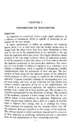
Driving an Inclined Ramp
Shaft Location<br />
For a permanent shaft there are 2 main<br />
requirements, which may be in conflict with<br />
each other.<br />
•First, the shaft should be located <strong>to</strong><br />
provide the most economical length of<br />
haulage, considering the entire mine<br />
plan.<br />
•Second, <strong>to</strong> ensure long life <strong>and</strong> a<br />
minimum of repairs, the shaft should be<br />
sunk in firm, stable rock.
Shaft Location<br />
a) Dipping Veins<br />
Most mines favour vertical<br />
shafts because there are now<br />
more sophisticated systems <strong>to</strong><br />
dig them <strong>and</strong> hositing speeds<br />
are greater. The choice of<br />
location of a vertical shaft in a<br />
narrow vein is shown above.<br />
Position 1 is favoured because<br />
in a dipping vein, the hanging<br />
wall is more apt <strong>to</strong> move in<strong>to</strong><br />
any mining operations than the<br />
footwall. .The disadvantage <strong>to</strong><br />
this position is the increase in<br />
length of crosscuts as the shaft<br />
gets deeper
) Vertical veins<br />
In a vertical deposit, both walls<br />
may become weakened <strong>and</strong><br />
move in<strong>to</strong> the mined out area. If<br />
the shaft is <strong>to</strong>o close <strong>to</strong> the<br />
deposit it will become unstable<br />
because of the walls moving in<strong>to</strong><br />
the mined out area. Either the<br />
shaft should be located beyond<br />
the area influenced by the<br />
subsidence angle, or <strong>to</strong> keep the<br />
wall rock stable, the area will<br />
have <strong>to</strong> be filled in as the ore is<br />
mined.
C) Ramps<br />
With the increased use of<br />
LHD equipment, ramps or<br />
declines are popular ways<br />
of developing a dipping<br />
deposit. The ramp is<br />
normally driven in the<br />
footwall at a grade of 10 <strong>to</strong><br />
15%.<br />
• Ramp : a heading containing horizontal curves used <strong>to</strong> as a<br />
transport corridor for rubber-tired mobile equipment.<br />
• Decline : a straight heading suitable for installation of belt<br />
conveyors or mobile equipment
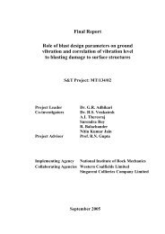
Bored Shafts
Lateral Development<br />
For underground hard rock<br />
mines, the term "lateral<br />
development" means the<br />
horizontal headings in a<br />
mine,such as drifts <strong>and</strong> crosscuts<br />
on a mine level. Lateral<br />
development includes the<br />
inclined headings (ramps <strong>and</strong><br />
declines) between levels.<br />
The traditional drill <strong>and</strong> blast<br />
method remains the least<br />
expensive <strong>and</strong> most practical<br />
means of advancing lateral<br />
headings.
Track versus Trackless<br />
A "track" mine refers <strong>to</strong> one that has rail<br />
installed in its lateral headings <strong>to</strong> provide<br />
travel for trains drawn by battery-operated,<br />
trolly, or diesel locomotives. A "trackless"<br />
or "mechanized mine" refers <strong>to</strong> the use of<br />
rubber tired mobile equipment <strong>to</strong> advance<br />
the later development <strong>and</strong> haul the ore.<br />
The trend has been away from track<br />
development. Trackless methods provide<br />
better flexibility. Both the productivity (ie.<br />
feet per man-shift) <strong>and</strong> rate of advance (ie.<br />
feet per month) are normally significantly<br />
higher for trackless headings
Design <strong>and</strong> Function<br />
Design starts with determining the<br />
cross-section of the drift, cross-cut<br />
, ramp or decline. Headings are<br />
con<strong>to</strong>ured <strong>to</strong> the minimum<br />
dimensions required <strong>to</strong> safely<br />
permit passage of the largest<br />
vechicle while providing space for<br />
roadway dressing, ditches, utility<br />
lines <strong>and</strong> ventilation duct. Safe<br />
clearances <strong>and</strong> the spacings of<br />
safety bays are specified in the<br />
Mines Act.
In the recent past,the size of mine<br />
headings has increased <strong>to</strong><br />
accommodate larger vechicles. But if<br />
the heading becomes <strong>to</strong>o large, it is not<br />
advanced as quickly <strong>and</strong> slows down<br />
mine development.<br />
Employing remote operation <strong>and</strong><br />
guidance systems that enable one<br />
opera<strong>to</strong>r <strong>to</strong> run two or three units of<br />
equipment simultaneously allow<br />
greater productivity improvement than<br />
further increasing opening sizes.
Design <strong>and</strong> Function<br />
For trackless headings are normally<br />
arched, it is common practice <strong>to</strong><br />
hang the vent duct <strong>and</strong> utility lines<br />
on the ditch side <strong>to</strong> save space <strong>and</strong><br />
help protect them from wayward<br />
vechicles.<br />
The back of these headings may be<br />
gently arched or driven flat backed,<br />
depending on the ground conditions.
Laser Control<br />
His<strong>to</strong>rically, both conventional <strong>and</strong><br />
trackless development headings<br />
were driven using st<strong>and</strong>ard line <strong>and</strong><br />
grade plugs as a means of<br />
controlling the azimuth <strong>and</strong> gradient<br />
of the heading. As the distance<br />
between control points <strong>and</strong> the face<br />
increases, the quality of control<br />
diminishes. Typically,line <strong>and</strong> grade<br />
plugs are useful for about 280 feet<br />
<strong>and</strong> then new controls must be<br />
installed
Laser Control<br />
Grade plugs are installed in the walls of the<br />
heading. Line plugs are installed in the back,<br />
<strong>and</strong> may or not include a survey control point.<br />
Both types of controls are frequently damaged<br />
during regular mining practice.<br />
For straight development headings that exceed<br />
800 feet in length, the solution <strong>to</strong> these<br />
problems is the use of laser beams.
Drift Location<br />
Most drifts are permanent <strong>and</strong> used<br />
throughout the life of the mine. It is<br />
important that drifts be located in<br />
positions where they can be preserved.
Drift Cycle<br />
Phase 1<br />
In a freshly blasted heading, the first thing that is done is <strong>to</strong> scale or bar<br />
down loose rocks, then water the walls <strong>and</strong> muck pile <strong>to</strong> control dust.
Drift Cycle<br />
Phase 2<br />
Once the ore is broken, it is mucked out <strong>and</strong> removed by mucking<br />
machine or LHD.
Drift Cycle<br />
Phase 3<br />
After all of the muck is removed, the<br />
heading is rock bolted or timbered.
Drift Cycle<br />
Phase 4<br />
If no ground support is needed,<br />
then drilling of the next round is<br />
started. A jackleg drill is usually<br />
used but jumbo drills are<br />
becoming popular.<br />
Jackleg<br />
Jumbo
Drift Cycle<br />
Phase 4<br />
A burn-cut round is used <strong>to</strong> break the advancing heading.
Drift Cycle<br />
Phase 5<br />
Loading the round comes next. The first stick of explosive that goes in<strong>to</strong><br />
the hole is called the de<strong>to</strong>na<strong>to</strong>r stick, which contains the cap <strong>and</strong> fuse. The<br />
rest of the hole is then filled with explosive.
Once the opening has been blasted the cycle starts again.
Vertical Development<br />
a) Raise Machines (Alimak)<br />
A recent development in<br />
driving raises is the<br />
mechanical raise- climbing<br />
machine, which runs on a<br />
track fastened <strong>to</strong> the sides<br />
of the raise. It includes a<br />
drilling platform <strong>and</strong> a<br />
means of hauling supplies<br />
up the raise.
Vertical Development<br />
b) Timbered Raise Cycle<br />
A s<strong>to</strong>per drill is commonly used for drilling in a raise.
Vertical Development<br />
The V-cut type of round or drill pattern is popular.
Before blasting down the round, the timber below must be protected <strong>and</strong><br />
the blasted rock must be directed in<strong>to</strong> an orepass or chute.<br />
A common procedure is <strong>to</strong> direct the ore in<strong>to</strong> a slide, which keeps the<br />
broken ore from dropping down the manway. The timbers that are directly<br />
exposed <strong>to</strong> the blast are covered with lagging. The round is then loaded<br />
<strong>and</strong> blasted.
After the blast, the loose rock needs <strong>to</strong> be cleaned away <strong>and</strong> water is used<br />
<strong>to</strong> control the dust. The loose rock on the back <strong>and</strong> sides must be scaled<br />
down.
After the raise has been made safe, the manway slide is removed, a floor is<br />
built on <strong>to</strong>p of the timber set, <strong>and</strong> the timber for the next set is hoisted <strong>and</strong><br />
set in place where it is aligned <strong>and</strong> blocked tightly in<strong>to</strong> position.<br />
The cycle is<br />
then ready <strong>to</strong><br />
start again
Raise Machines<br />
A recent development in driving raises is the mechanical raise-climbing<br />
machine, which runs on a track fastened <strong>to</strong> the sides of the raise. It<br />
includes a drilling platform <strong>and</strong> a means of hauling supplies up the raise.<br />
When the climber gets <strong>to</strong> the<br />
<strong>to</strong>p of the raise, the miners<br />
climb on<strong>to</strong> the deck, scale<br />
down the loose rock, <strong>and</strong> are<br />
ready <strong>to</strong> drill. When drilling is<br />
complete, another section of<br />
track is added <strong>and</strong> the climber<br />
is moved down <strong>to</strong> a protected<br />
position.<br />
On this track is a row of teeth, which meshes with the gear on the raise climber.<br />
Turning the gear directs the climber up or down the raise. The climber is driven by<br />
compressed air.
Alimak Raise Cycle<br />
•Scaling<br />
•Drilling<br />
•Loading<br />
•<strong>Blasting</strong><br />
•Ventilation
Raise Bore Machines<br />
Hard rock can now be cut with various<br />
types of rotary bits so drilling or boring<br />
large diameter openings has become<br />
practical. A raise boring machine drills a<br />
pilot hole <strong>to</strong> the level below. A drill rod<br />
or shaft is extended through the hole <strong>to</strong><br />
the level below where a large diameter<br />
bit is fastened on.<br />
The raise bore machine lifts the bit <strong>and</strong><br />
creates a high force or thrust of the bit<br />
against the face while rotating the bit.<br />
The finished section is smooth <strong>and</strong> often<br />
support is not required.
Ramp Development<br />
A. Using a LHD<br />
B. Mucking Machine<br />
C. Clamshell Loader
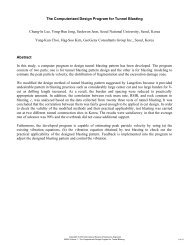
Develoment Costs<br />
DEVELOPMENT UNIT OP OP MAINT MAINT<br />
LABOUR SUPPLIES LABOUR SUPPLIES CONTRACTS TOTAL<br />
Ore Drives metre 272 540 153 106 0 1,071<br />
Crosscuts metre 320 635 180 125 0 1,260<br />
Ladder Raises metre 220 150 0 0 0 370<br />
Alimak Raises metre 0 0 0 0 1,100 1,100
You have reached the end of Unit 16