The Computerized Design Program for Tunnel Blasting - Mining and ...
The Computerized Design Program for Tunnel Blasting - Mining and ...
The Computerized Design Program for Tunnel Blasting - Mining and ...

You also want an ePaper? Increase the reach of your titles
YUMPU automatically turns print PDFs into web optimized ePapers that Google loves.
Abstract<br />
<strong>The</strong> <strong>Computerized</strong> <strong>Design</strong> <strong>Program</strong> <strong>for</strong> <strong>Tunnel</strong> <strong>Blasting</strong><br />
Chung-In Lee, Yong-Hun Jong, Seokwon Jeon, Seoul National University, Seoul, Korea<br />
Yong-Kun Choi, Hag-Soo Kim, GeoGeny Consultants Group Inc., Seoul, Korea<br />
In this study, a computer program to design tunnel blasting pattern has been developed. <strong>The</strong> program<br />
consists of two parts; one is <strong>for</strong> tunnel blasting pattern design <strong>and</strong> the other is <strong>for</strong> blasting modeling to<br />
estimate the peak particle velocity, the distribution of fragmentation <strong>and</strong> the excavation damage zone.<br />
We modified the design method of tunnel blasting pattern suggested by Lange<strong>for</strong>s because it provided<br />
undesirable pattern in blasting practices such as considerably large center cut <strong>and</strong> too large burden <strong>for</strong> Vcut<br />
as drilling length increased. As a result, the burden <strong>and</strong> spacing were reduced to practically<br />
appropriate amounts. In addition, the correlation between rock mass rate, RMR, <strong>and</strong> rock constant in<br />
blasting, c, was analyzed based on the data collected from twenty three tests of tunnel blasting. It was<br />
concluded that the correlation between them was fairly good enough to be applied in cut design. In order<br />
to check the validity of the modified methods <strong>and</strong> their practical applicability, test blasting was carried<br />
out at two different tunnel construction sites in Korea. <strong>The</strong> results were satisfactory in that the average<br />
rate of advance was 90% <strong>and</strong> the overbreak did not cause additional support.<br />
Futhermore, the developed program is capable of estimating peak particle velocity by using (a) the<br />
existing vibration equations, (b) the vibration equation obtained by test blasting to check out the<br />
practical applicability of the designed blasting pattern. Feedback is implemented into the program to<br />
adjust the designed blasting pattern <strong>and</strong> control the vibration.<br />
Copyright © 2005 International Society of Explosives Engineers<br />
2005G Volume 1 - <strong>The</strong> <strong>Computerized</strong> <strong>Design</strong> <strong>Program</strong> <strong>for</strong> <strong>Tunnel</strong> <strong>Blasting</strong> 1 of 10
Introduction<br />
<strong>The</strong> design of a blasting pattern is important <strong>for</strong> determining the blasting efficiency, tunnel wall damage,<br />
the vibration <strong>and</strong> the noise level caused by the blast. <strong>The</strong> allowable peak particle velocity with respect to<br />
any adjacent structures <strong>and</strong> the powder factor depend on the optimum pattern selection. However, in<br />
Korean tunnel construction sites, blasting operations have been per<strong>for</strong>med on the basis of the experience<br />
of blasting engineers. <strong>The</strong>re<strong>for</strong>e, there may be some differences between the designed pattern <strong>and</strong> the<br />
real drilling pattern.<br />
In order to eliminate this difference <strong>and</strong> st<strong>and</strong>ardize a tunnel blasting pattern, the development of a<br />
computerized design program <strong>for</strong> tunnel blasting has been carried out. In Korea, an automated design<br />
program <strong>for</strong> tunnel blasting was developed by Choi (1998), based on the method suggested by Lange<strong>for</strong>s<br />
(Lange<strong>for</strong>s <strong>and</strong> Kihlström, 1978). <strong>The</strong> program was modified by Kim (1999), based on the results of<br />
several test blasts. However, the program had a disadvantage in that the geological conditions were<br />
inadequately considered due to a lack of the test blasts. As a complementary measure of this<br />
disadvantage, the correlation between the RMR <strong>and</strong> the rock constant (c) was investigated using the<br />
results of many tunnel blasts. Moreover, the <strong>for</strong>mulae <strong>for</strong> the tunnel blast design suggested by Lange<strong>for</strong>s<br />
(abbreviated as Lange<strong>for</strong>s’ <strong>for</strong>mulae, hereafter) was modified based on the correlation <strong>and</strong> the results of<br />
the test tunnel blasts. <strong>The</strong> computerized design program <strong>for</strong> tunnel blasting was developed with the<br />
modified <strong>for</strong>mulae.<br />
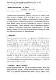
Conventional <strong>Design</strong>ing Method of <strong>Tunnel</strong> <strong>Blasting</strong><br />
Among the various practical design methods of the tunnel blasting pattern, the Swedish method<br />
suggested by Lange<strong>for</strong>s has been most widely accepted. It considers the influence of the rock on blasting<br />
represented by a ‘rock constant’, designated c, representing the base charge concentration required <strong>for</strong> a<br />
satisfactory blasting per<strong>for</strong>mance. <strong>The</strong> <strong>for</strong>mulae are provided to describe how the powder factor <strong>and</strong> the<br />
other blast design parameters should be varied <strong>for</strong> a particular blasting geometry. <strong>The</strong> following are the<br />
controlling parameters used in the Swedish method.<br />
• Rock constant<br />
• Drill hole diameter, Look-out, Drilled depth<br />
• Empty drill hole diameter, Number of empty drill holes (if case of Burn-cut)<br />
• Weight strength of explosive<br />
Stoping<br />
Contour<br />
Stoping<br />
Cut<br />
Lifter<br />
Stoping<br />
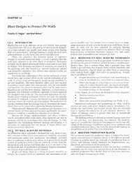
Figure 1: Classification of tunnel cross section by blasting conditions<br />
Copyright © 2005 International Society of Explosives Engineers<br />
2005G Volume 1 - <strong>The</strong> <strong>Computerized</strong> <strong>Design</strong> <strong>Program</strong> <strong>for</strong> <strong>Tunnel</strong> <strong>Blasting</strong> 2 of 10
<strong>The</strong> tunnel cross section is divided into 4 main parts (Figure 1): Cut, Stoping, Lifter <strong>and</strong> Contour. <strong>The</strong><br />
Cut section is classified into the Burn-Cut <strong>and</strong> the V-Cut.<br />
<strong>The</strong> essential design parameters <strong>for</strong> tunnel blasting include the burden, spacing <strong>and</strong> the explosive charge.<br />
<strong>The</strong>y differ in both different rock mass <strong>and</strong> blasting conditions. <strong>The</strong>re<strong>for</strong>e, a different section will have<br />
different design parameters on the basis of the calculation results obtained from the Swedish method.<br />
However this calculating method was obtained from the tests conducted on the stiff rocks in Sc<strong>and</strong>inavia.<br />
<strong>The</strong>re<strong>for</strong>e, specific field trials are recommended in order to optimize a blasting design <strong>for</strong> rock that<br />
differs either in the strength or structural characteristics from the Sc<strong>and</strong>inavian granites in reference.<br />
Modified <strong>Design</strong>ing Method of <strong>Tunnel</strong> <strong>Blasting</strong><br />
Determination of Rock Constant(c)<br />
<strong>The</strong> rock constant, c, is an empirical measure of the quantity of explosive required to loosen 1 m 3 of<br />
rock. When blasting in different Swedish rocks, it has been found that the value <strong>for</strong> c lies in the vicinity<br />
of 0.4 kg/m 3 . <strong>The</strong> c-value can be determined by trial blasting in a vertical drill hole with a hole diameter<br />
of approximately 32 mm. <strong>The</strong> vertical bench will be approximately 0.5 to 1 m high. <strong>The</strong> drill hole will<br />
have a depth of 1.3B, <strong>and</strong> the burden will be equal to the bench height. <strong>The</strong> c-value is obtained by<br />
multiplying the amount of explosive used per cubic meter of rock by a factor of 1.2, which was obtained<br />
by trial <strong>and</strong> error <strong>and</strong> from practical experience. <strong>Blasting</strong> in brittle crystalline granite gave a c-value<br />
equal to 0.2 kg/m 3 . <strong>Blasting</strong> in rock with a strata perpendicular to the blast direction occasionally gave a<br />
c-value ranging from 0.5 to 1.0 kg/m 3 . In practice, all other normal fissured rock materials, from<br />
s<strong>and</strong>stone to granite, can be described by a c-value of approximately 0.4 kg/m 3 (Persson et al., 1994).<br />
However it was difficult to obtain c-values by trial blasting in the field under tunnel construction.<br />
<strong>The</strong>re<strong>for</strong>e, in order to obtain the c-values easily, this study analyzed the correlation between the c-values<br />
<strong>and</strong> the RMR that is generally used as a criterion of rock classification <strong>for</strong> tunnel design in Korea. <strong>The</strong> cvalues<br />
were estimated by substituting the blasting results into the Lange<strong>for</strong>s’ <strong>for</strong>mulae. <strong>The</strong> estimation<br />
had an assumption that an advance rate of > 85% is accompanied by an ideal charge condition in the<br />
tunnel blasting.<br />
<strong>The</strong> data used <strong>for</strong> the linear regression analysis between the RMR <strong>and</strong> the rock constant(c), were<br />
collected at highway construction sites in Korea. Equation (1) shows the analysis result using 23 data<br />
sets <strong>and</strong> the correlation coefficient was 0.804 (Figure 2).<br />
−3 c = 5.<br />
73×<br />
10 RMR + 0.<br />
057<br />
(1)<br />
Modification of <strong>Design</strong> Formulae <strong>for</strong> Cut Section<br />
<strong>The</strong> Lange<strong>for</strong>s’ <strong>for</strong>mulae were modified to consider both the geological <strong>and</strong> explosives conditions. Kim<br />
(2002) presented modified <strong>for</strong>mulae to determine the blasthole location (spacing <strong>and</strong> burden) <strong>and</strong> the<br />
charge weights per blasthole <strong>for</strong> the cut, the stoping, the lifter <strong>and</strong> the contour sections that is shown in<br />
Figure 1. However, the modified <strong>for</strong>mulae <strong>for</strong> the cut (i.e., Burn-cut <strong>and</strong> V-cut) section design are only<br />
mentioned in this paper.<br />
Copyright © 2005 International Society of Explosives Engineers<br />
2005G Volume 1 - <strong>The</strong> <strong>Computerized</strong> <strong>Design</strong> <strong>Program</strong> <strong>for</strong> <strong>Tunnel</strong> <strong>Blasting</strong> 3 of 10
5<br />
M18<br />
M20<br />
C (kg/m 3 )<br />
1.0<br />
0.8<br />
0.6<br />
0.4<br />
0.2<br />
C = 5.73x10 -3 RMR + 0.057<br />
R = 0.804<br />
0.0<br />
0 20 40 60 80 100<br />
RMR<br />
Figure 2: Correlation between the Rock Constant(c) <strong>and</strong> the RMR values<br />
M16<br />
M15<br />
M17<br />
M14<br />
M19<br />
M9<br />
M5<br />
M19<br />
M12<br />
M3 M1<br />
M13<br />
M7<br />
M11<br />
M14<br />
M17<br />
M16<br />
5<br />
M20<br />
300<br />
M15 M18<br />
400<br />
900<br />
Unit: [mm]<br />
1000<br />
1800<br />
1600<br />
5<br />
7<br />
8<br />
M18<br />
M15<br />
M19<br />
M7 M11<br />
(a) Cut designed by Lange<strong>for</strong>s’ <strong>for</strong>mulae (b) Cut designed by modified <strong>for</strong>mulae<br />
Figure 3: Comparison of cut design (H=4.5 m, c=0.46 kg/m 3 )<br />
Firstly, in case of the burn-cut, the cut section designed by the Lange<strong>for</strong>s’ <strong>for</strong>mulae had problems that a<br />
size of the cut section was designed largely in the given rock constant, shown as Figure 3(a), <strong>and</strong> the<br />
rock mass conditions was not adequately reflected. To correct the problems, the <strong>for</strong>mulae <strong>for</strong> the cut<br />
design were modified, based upon the results of tunnel blastings. <strong>The</strong> modified <strong>for</strong>mulae are as follows:<br />
1 st quadrangle : B1<br />
0.<br />
35<br />
= 1.<br />
5φ<br />
c<br />
(2)<br />
Linear charge concentration<br />
d ⋅φ<br />
⋅ c<br />
: l = 240<br />
S<br />
(3)<br />
ANFO<br />
2 nd <strong>and</strong> 3 rd quadrangle : B n = 1. 02 A'n−1⋅φ<br />
(4)<br />
4 th quadrangle <strong>and</strong> over : A n=<br />
2⋅ an−1<br />
(5)<br />
Copyright © 2005 International Society of Explosives Engineers<br />
2005G Volume 1 - <strong>The</strong> <strong>Computerized</strong> <strong>Design</strong> <strong>Program</strong> <strong>for</strong> <strong>Tunnel</strong> <strong>Blasting</strong> 4 of 10<br />
M13<br />
5<br />
M17<br />
M4<br />
M17<br />
5<br />
M9<br />
M19<br />
M15<br />
M18<br />
5<br />
8
where φ is the diameter of the empty drill hole (in meters), a is the distance between a blasthole <strong>and</strong> a<br />
center of the cut section (in meters), d is the diameter of blastholes (in meters), l is the linear charge<br />
concentration (in kg/m), SANFO is the weight strength relative to ANFO, <strong>and</strong> Bn <strong>and</strong> An are the burden <strong>and</strong><br />
the side length of n th quadrangle (in meters), respectively.<br />
In the original Lange<strong>for</strong>s’ <strong>for</strong>mulae, a burden of the 1 st quadrangle is only determined by the diameter of<br />
the empty drill hole. However, in a practical tunnel blasting operation, the burden is determined<br />
according to the rock mass conditions. <strong>The</strong>re<strong>for</strong>e the original <strong>for</strong>mula was modified according to<br />
equation (2), i.e., the modified <strong>for</strong>mula reflected the rock mass conditions. Furthermore, in the case of<br />
using the original <strong>for</strong>mulae, the 5 th <strong>and</strong> 6 th quadrangles occupy a domain of the inner quadrangle, as<br />
shown in Fig. 3(a). <strong>The</strong>re<strong>for</strong>e the explosive energy is not used effectively. Consequently, the modified<br />
<strong>for</strong>mula (equation (5)) determines the burden of the quadrangle more than 5 th geometrically (Figure<br />
3(b)) to consume the explosive energy efficiently.<br />
Secondly, the tunnel design that uses the Lange<strong>for</strong>s’ <strong>for</strong>mulae <strong>for</strong> the V-cut increases both the burden<br />
<strong>and</strong> the charge weight per blasthole. As a result, the <strong>for</strong>mulae are inappropriate <strong>for</strong> a tunnel construction<br />
site. Modification of the V-cut design <strong>for</strong>mulae focuses on a correcting this.<br />
In the original Lange<strong>for</strong>s’ <strong>for</strong>mulae, the burden is a linear function of a drill hole diameter. <strong>The</strong> cut<br />
design method does not reflect the rock mass conditions <strong>and</strong> whenever the hole diameters are equal, the<br />
burden of the cut always has an equal value regardless of the rock mass conditions. To correct this, the<br />
optimum burden of the cut is calculated by equation (6).<br />
0.<br />
35<br />
B = 21 . 5d<br />
×<br />
(6)<br />
c<br />
<strong>The</strong> modified <strong>for</strong>mula reflects the rock mass conditions by setting the rock constant on the basis of 0.35<br />
kg/m 3 similar to the Burn-cut. In addition, the constant, 21.5, was determined from the collected data at<br />
the highway construction sites.<br />
<strong>The</strong> original <strong>for</strong>mula <strong>for</strong> determining the linear charge concentration q (in kg/m) does not reflect the<br />
rock mass conditions sufficiently, in the same way as the original <strong>for</strong>mulae <strong>for</strong> the burden of cut.<br />
<strong>The</strong>re<strong>for</strong>e the original <strong>for</strong>mula was modified (equation (7)).<br />
2<br />
c d<br />
q 1000<br />
S<br />
⋅<br />
= (7)<br />
ANFO<br />
<strong>The</strong> linear charge concentration in the column should be equal to the charge concentration <strong>for</strong> the<br />
bottom charge.<br />
<strong>The</strong>re<strong>for</strong>e the linear charge concentration (q) increases, as the rock mass conditions improve <strong>and</strong> the<br />
hole diameter increases, <strong>and</strong> decreases with increasing the relative strength of the explosive.<br />
Assessment of the Modified <strong>Design</strong> Formulae<br />
In order to validate the modified methods <strong>and</strong> their practical applicability, test blastings were carried out<br />
Copyright © 2005 International Society of Explosives Engineers<br />
2005G Volume 1 - <strong>The</strong> <strong>Computerized</strong> <strong>Design</strong> <strong>Program</strong> <strong>for</strong> <strong>Tunnel</strong> <strong>Blasting</strong> 5 of 10
at two different tunnel construction sites in Korea. At a crude oil storage cavern construction site, the<br />
modified design method using a Burn-cut was checked. <strong>The</strong> RMR values were 45 (<strong>for</strong> STA.0+408.4), 66<br />
(<strong>for</strong> STA0+20.5) <strong>and</strong> 71 (<strong>for</strong> STA.0+23.3). Table 1 shows the blasting results at the test site. In the other<br />
site, a highway construction site, the modified design method using a V-cut was examined. <strong>The</strong> RMR<br />
values were 58 (<strong>for</strong> STA.2+215.0), 59 (<strong>for</strong> STA.2+221.5), 54 (<strong>for</strong> STA.2+432.5) <strong>and</strong> 52 (<strong>for</strong><br />
STA.2+436.0). Table 2 shows the results of the tunnel test blasting using a V-cut.<br />
In Table 1 <strong>and</strong> 2, the results were satisfactory in that the average advance rate was 90% <strong>and</strong> the<br />
overbreak did not cause additional support.<br />
Table 1: <strong>Blasting</strong> results at the pipe tunnel <strong>and</strong> the water curtain tunnel (Burn-cut)<br />
Number of<br />
blastholes<br />
(Empty holes)<br />
Used charge<br />
weight<br />
(kg)<br />
Drilling<br />
length<br />
(m)<br />
Advance<br />
(m)<br />
Advance<br />
rate<br />
(%)<br />
Specific<br />
charge<br />
(kg/m 3 )<br />
STA.0+408.4 108 (2) 189.5 3.40 2.80 82.4 1.128<br />
STA.0+ 20.5 79 (2) 138.0 3.40 3.15 92.6 1.604<br />
STA.0+ 23.3 88 (2) 169.0 3.40 3.22 94.7 1.921<br />
Table 2: <strong>Blasting</strong> results of the highway tunnel (V-cut)<br />
Number of<br />
blastholes<br />
Used charge<br />
weight<br />
(kg)<br />
Drilling<br />
length<br />
(m)<br />
Advance<br />
(m)<br />
Advance<br />
rate<br />
(%)<br />
Specific<br />
charge<br />
(kg/m 3 )<br />
STA.2+215.0 120 260.9 3.7 3.30 89.0 0.820<br />
STA.2+221.5 117 257.7 3.5 3.04 86.9 0.879<br />
STA.2+432.5 130 280.0 3.8 3.51 92.4 0.828<br />
STA.2+436.0 115 245.0 3.3 3.08 93.3 0.825<br />
<strong>Computerized</strong> <strong>Design</strong> <strong>Program</strong> <strong>for</strong> <strong>Tunnel</strong> <strong>Blasting</strong><br />
A computerized design program, TunDesing3 <strong>for</strong> tunnel blasting was developed <strong>and</strong> was introduced by<br />
Lee et al (2002). Especially, Tun<strong>Design</strong> was originally intended to produce blasting pattern designs<br />
automatically. But, through several upgrades, the program has been strengthened to enable the user to<br />
reflect his knowledge <strong>and</strong> experience in producing pattern designs. In this study, the updated version,<br />
Tun<strong>Design</strong>4 of the original program will be introduced. Like the Tun<strong>Design</strong>3, the updated program<br />
consists of two parts; one is the ‘Pattern <strong>Design</strong> <strong>for</strong> <strong>Tunnel</strong>’ part <strong>and</strong> the other is the ‘<strong>Blasting</strong> Results<br />
Prediction’ part to estimate the particle velocity, the excavation damage zone <strong>and</strong> the rock fragmentation<br />
by blasting.<br />
Pattern <strong>Design</strong> <strong>for</strong> <strong>Tunnel</strong><br />
<strong>The</strong> developed program is adopted the modified <strong>for</strong>mulae (equation (2)~(7)) <strong>for</strong> the cut section <strong>and</strong> the<br />
modified <strong>for</strong>mulae that were studied by Kim (2002) <strong>for</strong> the stoping, the lifter <strong>and</strong> the contour sections.<br />
<strong>The</strong> program has many features including the features of the TunDesing3, which were introduced by Lee<br />
(2002). <strong>The</strong> additional features are as follows:<br />
• Flexibility on <strong>Tunnel</strong> Shapes. Tun<strong>Design</strong>4 can design blasting patterns with various tunnel shapes<br />
Copyright © 2005 International Society of Explosives Engineers<br />
2005G Volume 1 - <strong>The</strong> <strong>Computerized</strong> <strong>Design</strong> <strong>Program</strong> <strong>for</strong> <strong>Tunnel</strong> <strong>Blasting</strong> 6 of 10
created from not only existing templates but also AutoCAD drawings (Figure 4).<br />
Figure 4: <strong>Design</strong>ed pattern by the developed program <strong>for</strong> tunnel blasting<br />
• Easily Build the Draft of <strong>Blasting</strong> Pattern. This program has a Pattern Generating Engine (PGE) <strong>and</strong> an<br />
Automated Alignment Engine (AAE). <strong>The</strong> Tun<strong>Design</strong>4 provides you a draft, which is almost completed,<br />
when you only input some parameters <strong>for</strong> the PGE. Moreover, the AAE of time sequence will lead you<br />
to easy <strong>and</strong> quick arrangement of detonators.<br />
• Modifying <strong>Blasting</strong> Pattern. <strong>The</strong> Tun<strong>Design</strong>4 has a powerful editing function when you edit from the<br />
blasting patterns automatically created by the PGE or from the empty blasting patterns. You can edit the<br />
patterns easily <strong>and</strong> quickly by using an aligner, which can help you edit the blastholes. In addition, this<br />
program provides an intuitive interface so that you can arrange the detonator easily.<br />
• Sequential <strong>Blasting</strong>. It is possible to carry out the sequential blasting when there are too many<br />
blastholes <strong>and</strong> insufficient detonators (Figure 5). If you divide sequential regions, this program will<br />
automatically rearrange the detonators. You can check over the arranged detonators with Sequence<br />
Simulation.<br />
• Application of Various Cut. <strong>The</strong> program provides you various <strong>and</strong> automatically created cut, such as<br />
the cylinder-cut, the V-cut ad SUPEX-cut (Figure 6~8). Or you can make any shape of cut you want.<br />
Also you can import them from the other patterns.<br />
• Application of Various Explosives. <strong>The</strong> Tun<strong>Design</strong>4 has a capacity of using the bulk explosives <strong>and</strong><br />
the high-density charge of cartridge-type explosives.<br />
• Verifying the <strong>Blasting</strong> Pattern. With the Sequence Simulation, you can check it visually whether the<br />
detonators are well arranged or not.<br />
<strong>Blasting</strong> Results Prediction<br />
‘<strong>Blasting</strong> Results Prediction’ part of this program predicts the results of the tunnel blasting that was<br />
carried out according to the designed pattern. To confirm the designed pattern, this part was based on<br />
Copyright © 2005 International Society of Explosives Engineers<br />
2005G Volume 1 - <strong>The</strong> <strong>Computerized</strong> <strong>Design</strong> <strong>Program</strong> <strong>for</strong> <strong>Tunnel</strong> <strong>Blasting</strong> 7 of 10
previous studies. This program can predict the particle velocity, the rock fragmentation <strong>and</strong> the<br />
excavation damage zone.<br />
Figure 5: Blast pattern <strong>for</strong> the sequential<br />
blasting<br />
Figure 7: Blast pattern of the cut section using<br />
the V-cut<br />
Figure 6: Blast pattern of the cut section using<br />
the cylinder-cut<br />
Figure 8: Blast pattern of the cut section using<br />
the SUPEX-cut<br />
In this program, vibration equations are used to predict the vibration velocity of tunnel blasting based on<br />
the designed pattern. <strong>The</strong> vibration velocity can be predicted by two methods; one is to use the existing<br />
blasting vibration equations <strong>and</strong> the other is to use the results of test blasting at the tunnel construction<br />
site. <strong>The</strong> latter can more accurately predict the particle velocity than the <strong>for</strong>mer. Figure 9 shows the<br />
analysis results of the vibration velocity calculated from test blastings at a construction site.<br />
<strong>The</strong> Kuz-Ram model is adopted to predict the degree of rock fragmentation by blasting, which describes<br />
the size distribution of the blasted material. <strong>The</strong> model was developed by Cunningham (1983), <strong>and</strong> was<br />
based upon the size distribution curve of Rosin-Rammler <strong>and</strong> the empirical equation of the average<br />
Copyright © 2005 International Society of Explosives Engineers<br />
2005G Volume 1 - <strong>The</strong> <strong>Computerized</strong> <strong>Design</strong> <strong>Program</strong> <strong>for</strong> <strong>Tunnel</strong> <strong>Blasting</strong> 8 of 10
fragment size was obtained from the blast given by Kuznetsov (Jimeno et al., 1995). Figure 10 shows<br />
the output <strong>for</strong> predicting the fragmentation distribution by blasting.<br />
Figure 9: Analysis result of vibration velocity<br />
by test blastings<br />
Figure 10: Output of prediction results of the<br />
rock fragmentation by blasting<br />
This program adopts the strain damage model to predict the excavation damage zone by tunnel blasting.<br />
<strong>The</strong> most common outcome of the studies about the overbreak mechanisms is that the strain induced<br />
damage dominates. This may be true in very good quality rock masses but may not be as accurate as<br />
rock quality decreases. <strong>The</strong> model reported by Holmberg <strong>and</strong> Persson (1979) was used to estimate the<br />
vibration velocity around a blasthole (Forsyth, 1993). Figure 11 shows the output <strong>for</strong> predicting the<br />
excavation damage zone.<br />
Figure 11: Output of prediction results of the excavation damage zone<br />
Conclusions<br />
In this study, the design method suggested by Lange<strong>for</strong>s was modified based on the blasting results at<br />
highway tunnels in Korea to represent the design parameters quantitatively. Test blastings were carried<br />
out to test their practical applicability. In addition, the correlation between the rock constant <strong>and</strong> the<br />
Copyright © 2005 International Society of Explosives Engineers<br />
2005G Volume 1 - <strong>The</strong> <strong>Computerized</strong> <strong>Design</strong> <strong>Program</strong> <strong>for</strong> <strong>Tunnel</strong> <strong>Blasting</strong> 9 of 10
RMR was analyzed in order to quantify the rock mass conditions. By adopting these methods, the<br />
computerized design program <strong>for</strong> tunnel blasting has been developed with capacity of predicting<br />
blasting results.<br />
Acknowledgements<br />
<strong>The</strong> authors would like to acknowledge Tae-Hyung Kim, who is a graduate student in Ph.D. course, the<br />
Texas A&M University, <strong>for</strong> spending a lot of time <strong>and</strong> ef<strong>for</strong>t on the test blastings in his study of Master’s<br />
thesis, Seoul National University.<br />
References<br />
Choi, Y. -M., 1998, “A Study on the Development of Automated <strong>Design</strong> <strong>Program</strong> <strong>for</strong> <strong>Tunnel</strong> <strong>Blasting</strong>”,<br />
Master’s thesis, Seoul National University, Seoul (in Korean).<br />
Cunningham, C., 1993, “<strong>The</strong> Kuz-Ram Model <strong>for</strong> production of fragmentation <strong>for</strong>m blasting”, Proc. 1 st<br />
Symp. on Rock Fragmentation by <strong>Blasting</strong>, Lülea.<br />
Forsyth, W.W., 1993, “A discussion of blast-induced overbreak around underground excavation”, Proc.<br />
4 th Symp. on Rock Fragmentation by <strong>Blasting</strong>, pp.161-166.<br />
Holmberg, R. <strong>and</strong> Persson, R.-A., 1979, “<strong>Design</strong> of tunnel perimeter blasthole patterns to prevent rock<br />
damage”. Proc. IMM <strong>Tunnel</strong>ling ’79 Conference, London, pp. 3-6.<br />
Jimeno, C.-L., Jimeno, E.-L. <strong>and</strong> Carcedo, F.-J.-A., 1995, “Drilling <strong>and</strong> <strong>Blasting</strong> of Rocks”,<br />
A.A.Balkema, Rotterdam, Brookfield, pp.326-331.<br />
Kim, K.-Y., 1999, “A Study on Automated <strong>Design</strong> of <strong>Tunnel</strong> <strong>Blasting</strong> Pattern Considering Rock Mass<br />
Rating”, Master’s thesis, Seoul National University, Seoul (in Korean).<br />
Kim, T.-H., 2002, “Quantitative Representation of <strong>Design</strong> Parameters <strong>for</strong> Automation of <strong>Tunnel</strong> <strong>Blasting</strong><br />
Pattern <strong>Design</strong>”, Master’s thesis, Seoul National University, Seoul (in Korean).<br />
Lee, C.-I., Jong, Y. -H., Kim, T.-H., Choi, Y. -K., <strong>and</strong> Jeon. S., 2002, “Development of an automated<br />
design program <strong>for</strong> tunnel blasting”, Journal of the Japan Explosives Society, Vol. 63 (6), pp. 309-315.<br />
Lange<strong>for</strong>s, U. <strong>and</strong> Kihlström, B., 1978, “<strong>The</strong> Modern Technique of Rock <strong>Blasting</strong>”, John Wiley & Sons<br />
Inc.<br />
Persson, P.-A., Holmberg, R. <strong>and</strong> Lee, J., 1994, “Rock <strong>Blasting</strong> <strong>and</strong> Explosives Engineering”, CRC<br />
Press, Boca Raton, Florida, pp. 197.<br />
Copyright © 2005 International Society of Explosives Engineers<br />
2005G Volume 1 - <strong>The</strong> <strong>Computerized</strong> <strong>Design</strong> <strong>Program</strong> <strong>for</strong> <strong>Tunnel</strong> <strong>Blasting</strong> 10 of 10