Underground Mine Design in Surpac Vision - Mining and Blasting
Underground Mine Design in Surpac Vision - Mining and Blasting
Underground Mine Design in Surpac Vision - Mining and Blasting

Create successful ePaper yourself
Turn your PDF publications into a flip-book with our unique Google optimized e-Paper software.
<strong>Underground</strong> <strong>M<strong>in</strong>e</strong> <strong>Design</strong><br />
<strong>in</strong> <strong>Surpac</strong> <strong>Vision</strong><br />
September 2006
Copyright © 2006 <strong>Surpac</strong> <strong>M<strong>in</strong>e</strong>x Group Pty Ltd (A Gemcom Company). All rights<br />
reserved.<br />
This software <strong>and</strong> documentation is proprietary to <strong>Surpac</strong> <strong>M<strong>in</strong>e</strong>x Group Pty Ltd.<br />
<strong>Surpac</strong> <strong>M<strong>in</strong>e</strong>x Group Pty Ltd publishes this documentation for the sole use of <strong>Surpac</strong> licenses.<br />
Without written permission you may not sell, reproduce, store <strong>in</strong> a retrieval system, or transmit<br />
any part of the documentation. For such permission, or to obta<strong>in</strong> extra copies please contact<br />
your local <strong>Surpac</strong> <strong>M<strong>in</strong>e</strong>x Group Office.<br />
<strong>Surpac</strong> <strong>M<strong>in</strong>e</strong>x Group Pty Ltd<br />
Level 8 190 St Georges Terrace<br />
Perth, Western Australia 6000<br />
Telephone: (08) 94201383<br />
Fax: (08) 94201350<br />
While every precaution has been taken <strong>in</strong> the preparation of this manual, we assume no<br />
responsibility for errors or omissions. Neither is any liability assumed for damage result<strong>in</strong>g<br />
from the use of the <strong>in</strong>formation conta<strong>in</strong>ed here<strong>in</strong>.<br />
All br<strong>and</strong> <strong>and</strong> product names are trademarks or registered trademarks of there respective<br />
companies.<br />
About This Manual<br />
This manual has been designed to provide a practical guide to the many uses of the software.<br />
The applications conta<strong>in</strong>ed with<strong>in</strong> this manual are by no means exhaustive as the possible<br />
uses of the software are only limited by the user’s imag<strong>in</strong>ation. However, it will give new users<br />
a start<strong>in</strong>g po<strong>in</strong>t <strong>and</strong> exist<strong>in</strong>g users a good overview by demonstrat<strong>in</strong>g how to use many of the<br />
functions <strong>in</strong> <strong>Surpac</strong> <strong>Vision</strong>. If you have any difficulties, or questions while work<strong>in</strong>g through this<br />
manual feel free to contact your local <strong>Surpac</strong> <strong>M<strong>in</strong>e</strong>x Group Office.<br />
Contributors<br />
Rowdy Bristol<br />
Phil Jackson<br />
<strong>Surpac</strong> <strong>M<strong>in</strong>e</strong>x Group<br />
Perth, Western Australia<br />
Product<br />
<strong>Surpac</strong> <strong>Vision</strong> v5.2<br />
2
Table of Contents<br />
Introduction................................................................................................................................1<br />
Requirements ............................................................................................................................ 1<br />
Objectives .................................................................................................................................. 1<br />
Workflow .................................................................................................................................... 2<br />
<strong>Underground</strong> <strong>Design</strong> Concepts ................................................................................................. 3<br />
Creat<strong>in</strong>g a Centrel<strong>in</strong>e <strong>Design</strong> .................................................................................................... 4<br />
1. View<strong>in</strong>g the data ........................................................................................................... 4<br />
2. Creat<strong>in</strong>g a centrel<strong>in</strong>e between ore zones..................................................................... 5<br />
3. Creat<strong>in</strong>g access drives to the ore zones ...................................................................... 9<br />
4. Creat<strong>in</strong>g the ma<strong>in</strong> decl<strong>in</strong>e........................................................................................... 15<br />
5. Creat<strong>in</strong>g a DTM from centrel<strong>in</strong>es <strong>and</strong> profiles............................................................ 25<br />
3
Introduction<br />
There are many types of designs employed <strong>in</strong> underground m<strong>in</strong><strong>in</strong>g. Although there are<br />
numerous requirements for each design, <strong>Surpac</strong> can assist you to create practically any type<br />
of m<strong>in</strong>e design.<br />
Requirements<br />
Prior to proceed<strong>in</strong>g with this tutorial, you will need:<br />
• <strong>Surpac</strong> <strong>Vision</strong> v5.2 <strong>in</strong>stalled<br />
• The dataset accompany<strong>in</strong>g this tutorial<br />
Objectives<br />
The objective of this tutorial is to allow you to underst<strong>and</strong> some of the str<strong>in</strong>g edit<strong>in</strong>g tools<br />
available <strong>in</strong> <strong>Surpac</strong> to create a decl<strong>in</strong>e <strong>and</strong> production access po<strong>in</strong>ts <strong>in</strong>to stopes.<br />
1
Workflow<br />
The process of perform<strong>in</strong>g underground m<strong>in</strong>e design described <strong>in</strong> this tutorial is but one of<br />
many different approaches. There is no s<strong>in</strong>gle set of steps which is generally employed <strong>in</strong> the<br />
process. You may want to start from the top <strong>and</strong> go down, from the bottom <strong>and</strong> design up, or<br />
start <strong>in</strong> the middle of the deposit <strong>and</strong> proceed up <strong>and</strong> down at the same time. The workflow<br />
you adopt will generally be the one which you f<strong>in</strong>d best for your scenario.<br />
In this example the workflow is as follows:<br />
2
<strong>Underground</strong> <strong>Design</strong> Concepts<br />
Overview<br />
To create an underground m<strong>in</strong>e design us<strong>in</strong>g <strong>Surpac</strong> requires an underst<strong>and</strong><strong>in</strong>g of<br />
underground m<strong>in</strong><strong>in</strong>g term<strong>in</strong>ology <strong>and</strong> concepts. This section will cover some terms used <strong>in</strong><br />
this tutorial <strong>and</strong> some basic concepts of underground m<strong>in</strong>e design.<br />
Requirements<br />
Prior to perform<strong>in</strong>g the exercises <strong>in</strong> this chapter, some experience <strong>in</strong> underground m<strong>in</strong>e<br />
design is helpful, but not required.<br />
Term<strong>in</strong>ology<br />
• Centrel<strong>in</strong>e – a l<strong>in</strong>e which represents the centre of a drive. The centrel<strong>in</strong>e can be used<br />
to create solid models, or outl<strong>in</strong>es for plan view plots.<br />
• Drive – a tunnel, or open<strong>in</strong>g <strong>in</strong> rock, also known as a drift, or crosscut<br />
• Stope – a 3-dimensional area (usually ore) which is to be m<strong>in</strong>ed out by blast<strong>in</strong>g a<br />
series of long holes or r<strong>in</strong>g design holes<br />
<strong>Underground</strong> <strong>M<strong>in</strong>e</strong> <strong>Design</strong> Concepts <strong>in</strong> <strong>Surpac</strong><br />
There are many different scenarios where underground m<strong>in</strong>e designs are to be created. In<br />
this tutorial, we will use:<br />
• 3D solid models of designed stopes.<br />
• str<strong>in</strong>gs represent<strong>in</strong>g ore outl<strong>in</strong>es at each level where a design is to be created.<br />
• a po<strong>in</strong>t represent<strong>in</strong>g the location on the surface which is an entrance to the<br />
underground m<strong>in</strong>e.<br />
We will open files conta<strong>in</strong><strong>in</strong>g this data <strong>in</strong>to graphics, then use various edit<strong>in</strong>g <strong>and</strong> po<strong>in</strong>t<br />
creation tools to create the underground m<strong>in</strong>e design.<br />
Summary<br />
You should now be familiar with some of the concepts <strong>and</strong> terms used for underground<br />
design <strong>in</strong> <strong>Surpac</strong>. Review this chapter or consult the Onl<strong>in</strong>e Reference Manual if you are<br />
unclear about the def<strong>in</strong>itions used <strong>in</strong> this section. The next section demonstrates the steps<br />
<strong>in</strong>volved <strong>in</strong> creat<strong>in</strong>g an underground design centrel<strong>in</strong>e<br />
3
Creat<strong>in</strong>g a Centrel<strong>in</strong>e <strong>Design</strong><br />
Overview<br />
An underground design beg<strong>in</strong>s with the centrel<strong>in</strong>e. The creation of a centrel<strong>in</strong>e can be<br />
performed by many different functions with<strong>in</strong> <strong>Surpac</strong> <strong>Vision</strong>, but is basically the creation of<br />
three dimensional po<strong>in</strong>ts <strong>in</strong> space.<br />
Requirements<br />
Prior to perform<strong>in</strong>g the exercises <strong>in</strong> this chapter, you should have:<br />
• a basic knowledge of <strong>Surpac</strong> str<strong>in</strong>g files <strong>and</strong> edit<strong>in</strong>g tools, as covered <strong>in</strong> the<br />
Introduction manual<br />
1. View<strong>in</strong>g the data<br />
Open the file stopes1.dtm by dragg<strong>in</strong>g it <strong>in</strong>to Graphics. This file represents two parallel ore<br />
zones.<br />
Open the file ugdes_f<strong>in</strong>al1.dtm (may be <strong>in</strong> either the same layer or <strong>in</strong> a different layer - it<br />
does not matter).<br />
The file ugdes_f<strong>in</strong>al1.dtm is the end result of what we will be creat<strong>in</strong>g <strong>in</strong> this tutorial. It is a<br />
series of three-dimensional solid objects represent<strong>in</strong>g an underground m<strong>in</strong>e design.<br />
The transparency of the ore zones can be controlled by sett<strong>in</strong>g the transparency colour for the<br />
faces of object 8 to grey, or an RGB value of someth<strong>in</strong>g like r=0.7 g=0.7 b=0.7<br />
To set the transparency colour, from the Customise menu, select Display properties, then<br />
DTMs <strong>and</strong> 3DMs. The display properties will be activated for the current layer only.<br />
From the View menu, select Surface view options, then Hide triangle faces to turn the<br />
faces off. From the Display menu, select Str<strong>in</strong>gs, then With str<strong>in</strong>g numbers to display<br />
str<strong>in</strong>gs 2 to 11.<br />
Str<strong>in</strong>gs 2 to 11 represent the centrel<strong>in</strong>e str<strong>in</strong>g numbers <strong>in</strong> the f<strong>in</strong>al design we will be creat<strong>in</strong>g.<br />
4
You should see the follow<strong>in</strong>g:<br />
When you are f<strong>in</strong>ished view<strong>in</strong>g the data, select the Reset Graphics icon:<br />
2. Creat<strong>in</strong>g a centrel<strong>in</strong>e between ore zones<br />
We will now create a centrel<strong>in</strong>e midway between the two ore zones at the 200 level.<br />
Open the file lev215.str <strong>in</strong>to a new layer.<br />
This can easily be done by click<strong>in</strong>g <strong>and</strong> dragg<strong>in</strong>g the file <strong>in</strong> the navigator <strong>in</strong>to the graphics<br />
viewport, or by double click<strong>in</strong>g the file name <strong>in</strong> the navigator. Either of these actions will<br />
result <strong>in</strong> the file be<strong>in</strong>g opened <strong>in</strong>to a layer named lev215.str.<br />
The file lev215.str represents a small part of the exist<strong>in</strong>g work<strong>in</strong>gs at the 215 level. Str<strong>in</strong>g<br />
215 is the outl<strong>in</strong>e of the exist<strong>in</strong>g work<strong>in</strong>gs, <strong>and</strong> str<strong>in</strong>g 1 is the design centrel<strong>in</strong>e.<br />
This is the po<strong>in</strong>t at which the production crew will beg<strong>in</strong> m<strong>in</strong><strong>in</strong>g to implement our design. As<br />
you will see, although m<strong>in</strong><strong>in</strong>g will beg<strong>in</strong> at this po<strong>in</strong>t, we do not necessarily have to beg<strong>in</strong> the<br />
design at this po<strong>in</strong>t. In our case, we will actually beg<strong>in</strong> the design at the ore zone, <strong>and</strong> work<br />
back to this po<strong>in</strong>t. This is just one way of creat<strong>in</strong>g an underground m<strong>in</strong>e design for this data<br />
set. The ma<strong>in</strong> objective of this tutorial is to teach you the tools for creat<strong>in</strong>g an underground<br />
design. The manner <strong>in</strong> which you use these tools is up to you.<br />
Open the file stopes1.str <strong>in</strong>to a new layer, <strong>and</strong> sp<strong>in</strong> the data around to get an idea of how the<br />
str<strong>in</strong>gs are formed <strong>in</strong> 3D space.<br />
From the Display menu, select Str<strong>in</strong>gs, then With str<strong>in</strong>g numbers to display all str<strong>in</strong>g<br />
numbers.<br />
From the Inquire menu, select Po<strong>in</strong>t properties, <strong>and</strong> select several different segments.<br />
Notice that the str<strong>in</strong>g numbers are the same as the Z value of the str<strong>in</strong>gs.<br />
We will now create a design from the 200 level up to lev215.str, start<strong>in</strong>g at the 200 level.<br />
From the Display menu, select Hide everyth<strong>in</strong>g.<br />
From the Display menu, select Str<strong>in</strong>gs, then With str<strong>in</strong>g numbers, <strong>and</strong> display only str<strong>in</strong>g<br />
200.<br />
5
Set ma<strong>in</strong> graphics layer as the current layer. Note that ma<strong>in</strong> graphics layer conta<strong>in</strong>s<br />
noth<strong>in</strong>g at this po<strong>in</strong>t.<br />
As shown <strong>in</strong> the f<strong>in</strong>al design image shown previously, the str<strong>in</strong>g number used to create the<br />
ma<strong>in</strong> drive between the two ore zones is str<strong>in</strong>g 10.<br />
From the Create menu, select Digitise, then Properties (or use the design str<strong>in</strong>g number<br />
button, displayed <strong>in</strong> the status bar at the bottom of the ma<strong>in</strong> <strong>Surpac</strong> w<strong>in</strong>dow) to set the<br />
design str<strong>in</strong>g number, which will currently be set to str<strong>in</strong>g number 1:<br />
On the form that pops up, set the design str<strong>in</strong>g number to 10, <strong>and</strong> click Apply<br />
From the Create menu, select Digitise, then New midpo<strong>in</strong>t, <strong>and</strong> select two po<strong>in</strong>ts on the<br />
north end of the ore zones to create a po<strong>in</strong>t halfway between the two selected po<strong>in</strong>ts, as<br />
shown:<br />
From the Create menu, select Digitise, then New midpo<strong>in</strong>t, <strong>and</strong> select two po<strong>in</strong>ts on the<br />
south end of the ore zones to create a po<strong>in</strong>t halfway between the two selected po<strong>in</strong>ts, as<br />
shown:<br />
Click escape to term<strong>in</strong>ate the <strong>in</strong>put to the function. The Z value of the po<strong>in</strong>ts will be equal to<br />
the average of the Z values of the two selected po<strong>in</strong>ts. In this case, where the Z value of both<br />
po<strong>in</strong>ts is 200, the Z value of the new po<strong>in</strong>ts will be 200.<br />
Next, suppose we want to move the end of the drive (the first po<strong>in</strong>t created) 50 meters to the<br />
southeast, along the l<strong>in</strong>e between the two po<strong>in</strong>ts.<br />
6
First, set the mode to Change by select<strong>in</strong>g the item from the Status Items toolbar.<br />
From the Create menu, select Po<strong>in</strong>ts, then Onl<strong>in</strong>e between any po<strong>in</strong>ts.<br />
Select the first po<strong>in</strong>t created <strong>in</strong> str<strong>in</strong>g 10 (the po<strong>in</strong>t to be moved), then select the second po<strong>in</strong>t<br />
created <strong>in</strong> str<strong>in</strong>g 10.<br />
On the form, select Horizontal Distance, enter a distance of 50, <strong>and</strong> Apply the form.<br />
The first po<strong>in</strong>t will be moved 50 meters as shown below:<br />
Click escape to term<strong>in</strong>ate the <strong>in</strong>put to the function. Next, we will create po<strong>in</strong>ts along the<br />
centrel<strong>in</strong>e every 50 meters from the first po<strong>in</strong>t (the northern end of the drive) to the second<br />
po<strong>in</strong>t (the southern end of the drive).<br />
7
To create po<strong>in</strong>ts <strong>in</strong> the same segment, we need to set the mode to Insert. Change the mode<br />
from Change to Insert.<br />
From the Create menu, select Po<strong>in</strong>ts, then Multiple po<strong>in</strong>ts by subdivid<strong>in</strong>g.<br />
Select the northern end of str<strong>in</strong>g 10, then the southern end of str<strong>in</strong>g 10.<br />
Enter the follow<strong>in</strong>g, then Apply the form:<br />
New po<strong>in</strong>ts will be created every 50 meters from the first po<strong>in</strong>t to the second po<strong>in</strong>t. Click<br />
escape to term<strong>in</strong>ate the <strong>in</strong>put to the function.<br />
From the Display menu, select Po<strong>in</strong>t, then Numbers, <strong>and</strong> Apply the form to display po<strong>in</strong>t<br />
numbers for all po<strong>in</strong>ts <strong>in</strong> the ma<strong>in</strong> graphics layer.<br />
You will see that po<strong>in</strong>ts 2, 3, <strong>and</strong> 4 have now been <strong>in</strong>serted <strong>in</strong> between the northern endpo<strong>in</strong>t<br />
<strong>and</strong> the southern endpo<strong>in</strong>t of the centrel<strong>in</strong>e:<br />
These po<strong>in</strong>ts will serve as the start<strong>in</strong>g po<strong>in</strong>ts for the access po<strong>in</strong>ts to the ore zones.<br />
Save the centrel<strong>in</strong>e str<strong>in</strong>g to the file ugdes1.str<br />
8
If you want to see all of the steps performed <strong>in</strong> this chapter, either run or edit:<br />
_01_create_centrel<strong>in</strong>e_between_ore_zones.tcl<br />
Note: If the macro pauses, display<strong>in</strong>g “Click <strong>in</strong> graphics to cont<strong>in</strong>ue” <strong>in</strong> the message w<strong>in</strong>dow,<br />
you will need to click <strong>in</strong> graphics to allow the macro to cont<strong>in</strong>ue. Also, you will need to Apply<br />
the forms presented.<br />
3. Creat<strong>in</strong>g access drives to the ore zones<br />
We will now create centrel<strong>in</strong>es for these access drives from str<strong>in</strong>g 10 to the ore zones.<br />
Select the design str<strong>in</strong>g button on the status bar at the bottom of the ma<strong>in</strong> <strong>Surpac</strong> w<strong>in</strong>dow<br />
(currently display<strong>in</strong>g Str = 10).<br />
Enter a new design str<strong>in</strong>g number of 11, <strong>and</strong> Apply the form:<br />
Change the mode to Add.<br />
From the Create menu, select Po<strong>in</strong>ts, then By angle.<br />
Select po<strong>in</strong>t 2, then po<strong>in</strong>t 1.<br />
Enter a Distance of 0 <strong>and</strong> an Angle of 0, <strong>and</strong> Apply the form:<br />
This is only one way of creat<strong>in</strong>g a po<strong>in</strong>t <strong>in</strong> str<strong>in</strong>g 11 at the same location as po<strong>in</strong>t 1 <strong>in</strong> str<strong>in</strong>g 10.<br />
9
Next, we will create the endpo<strong>in</strong>t of the access drive with the same function.<br />
Without cancell<strong>in</strong>g the previous function, once aga<strong>in</strong> select po<strong>in</strong>t 2, then po<strong>in</strong>t 1 as before,<br />
enter the follow<strong>in</strong>g, then Apply the form:<br />
This will now create a new segment of str<strong>in</strong>g 11 that will extend beyond the western ore zone.<br />
We will clip this to the edge of the ore zone later.<br />
From the Create menu, select New segment.<br />
We need to do this between segments so that the end of the first segment is not connected to<br />
the beg<strong>in</strong>n<strong>in</strong>g of the second segment.<br />
From the Create menu, select Po<strong>in</strong>ts, then By angle.<br />
Select po<strong>in</strong>t 2, then po<strong>in</strong>t 1 aga<strong>in</strong>, enter a Distance of 0 <strong>and</strong> an Angle of 0, <strong>and</strong> Apply the<br />
form:<br />
10
Without cancell<strong>in</strong>g the previous function, once aga<strong>in</strong> select po<strong>in</strong>t 2, then po<strong>in</strong>t 1 as before,<br />
enter the follow<strong>in</strong>g, then Apply the form:<br />
We will now have two segments of str<strong>in</strong>g 11 represent<strong>in</strong>g the centrel<strong>in</strong>e of ore access drives<br />
left <strong>and</strong> right off the ma<strong>in</strong> drive.<br />
From the Display menu, select Hide temporary markers to remove the small markers<br />
created when you create or identify a po<strong>in</strong>t.<br />
We will now copy both segments of this str<strong>in</strong>g to po<strong>in</strong>ts 2, 3, <strong>and</strong> 4.<br />
Us<strong>in</strong>g the combobox on the Status Items toolbar, set the mode from No Snap to Po<strong>in</strong>t :<br />
11
From the Edit menu, select Str<strong>in</strong>g, then Copy.<br />
Select str<strong>in</strong>g 11 near po<strong>in</strong>t 1, <strong>and</strong> drag to po<strong>in</strong>t 2.<br />
In order to correctly select a str<strong>in</strong>g or segment <strong>in</strong> <strong>Surpac</strong> <strong>Vision</strong>, DO NOT select a po<strong>in</strong>t<br />
common to two or more str<strong>in</strong>gs. In this case, <strong>in</strong> order to select str<strong>in</strong>g 11, you would not want<br />
to position the cursor right on top of po<strong>in</strong>t 1, as this po<strong>in</strong>t is common to str<strong>in</strong>g 10 <strong>and</strong> str<strong>in</strong>g 11,<br />
<strong>and</strong> you could not be certa<strong>in</strong> exactly which str<strong>in</strong>g you will select. Instead, select the l<strong>in</strong>e near<br />
the po<strong>in</strong>t, as shown:<br />
Incorrect Correct<br />
After select<strong>in</strong>g str<strong>in</strong>g 11 as shown above, <strong>and</strong> dragg<strong>in</strong>g it to po<strong>in</strong>t 2, release, fill <strong>in</strong> the form as<br />
follows, <strong>and</strong> Apply the form:<br />
A copy of both segments of str<strong>in</strong>g 11 will now be created at po<strong>in</strong>t 2:<br />
Note that there are exactly two additional po<strong>in</strong>ts on str<strong>in</strong>g 10 (po<strong>in</strong>t 3 <strong>and</strong> po<strong>in</strong>t 4) where we<br />
need access drives. We can simply cont<strong>in</strong>ue the Str<strong>in</strong>g Copy function to create drives for<br />
these po<strong>in</strong>ts.<br />
12
While still <strong>in</strong> the function Str<strong>in</strong>g Copy, select str<strong>in</strong>g 11 aga<strong>in</strong> near po<strong>in</strong>t 1. Drag to po<strong>in</strong>t 3,<br />
release, fill <strong>in</strong> the form as before, <strong>and</strong> Apply the form:<br />
Click Escape to term<strong>in</strong>ate the <strong>in</strong>put to the function.<br />
Now all eight access drives are created:<br />
The last step is to trim the access drives back to the ore zones.<br />
From the Edit menu, select Trim, then Clip by selected segment. Select <strong>in</strong>side, then<br />
Apply the form:<br />
Select one segment of str<strong>in</strong>g 200.<br />
All portions of segments <strong>in</strong>side the selected ore zone will be removed. When the form<br />
appears aga<strong>in</strong>, leave it set to <strong>in</strong>side <strong>and</strong> Apply the form:<br />
Select the other ore zone.<br />
When the form appears aga<strong>in</strong>, Cancel it.<br />
13
You should now see all portions of segments <strong>in</strong>side both ore zones removed:<br />
All that rema<strong>in</strong>s to do is to remove the portions of str<strong>in</strong>g 11 extended beyond the ore zones.<br />
From the Edit menu, select Segment, then Delete, <strong>and</strong> select the portion of each segment<br />
extended beyond the ore zones.<br />
From the Display menu, select Hide temporary markers.<br />
When you are f<strong>in</strong>ished, you should see the follow<strong>in</strong>g:<br />
Save the file aga<strong>in</strong> as ugdes1.str, overwrit<strong>in</strong>g the previous contents.<br />
If you want to see all of the steps performed <strong>in</strong> this chapter, either run or edit:<br />
_02_create_access_drives_to_ore_zones.tcl<br />
Note: If the macro pauses, display<strong>in</strong>g “Click <strong>in</strong> graphics to cont<strong>in</strong>ue” <strong>in</strong> the message w<strong>in</strong>dow,<br />
you will need to click <strong>in</strong> graphics to allow the macro to cont<strong>in</strong>ue. Also, you will need to Apply<br />
the forms presented.<br />
14
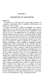
4. Creat<strong>in</strong>g the ma<strong>in</strong> decl<strong>in</strong>e<br />
We will now create the decl<strong>in</strong>e from the access po<strong>in</strong>t on the 215 level to the southern end of<br />
the ma<strong>in</strong> drive between the two ore zones, as illustrated below. The curve numbers given<br />
here will be referred to throughout the rema<strong>in</strong>der of this section of the tutorial.<br />
Prior to commenc<strong>in</strong>g this design, here are a few design constra<strong>in</strong>ts:<br />
• The gradient from the Access Po<strong>in</strong>t to the Start of the Decl<strong>in</strong>e will be flat.<br />
• The gradient from the Start of the Decl<strong>in</strong>e to the End of the Decl<strong>in</strong>e can be no more<br />
than 15%<br />
• Curve 1 will have a radius of 20 meters.<br />
• Curves 2 <strong>and</strong> 3 will have a radius of 30 meters.<br />
• There must be a 5 meter straight section between curves 2 <strong>and</strong> 3.<br />
Make lev215.str the active layer<br />
15
From the Display menu, select Str<strong>in</strong>gs, then With str<strong>in</strong>g numbers, to display all str<strong>in</strong>gs <strong>in</strong><br />
the layer.<br />
As was previously mentioned, str<strong>in</strong>g 215 is the outl<strong>in</strong>e of the exist<strong>in</strong>g work<strong>in</strong>gs, <strong>and</strong> str<strong>in</strong>g 1 is<br />
the design centrel<strong>in</strong>e. The end of str<strong>in</strong>g 1 is the po<strong>in</strong>t which our design must tie <strong>in</strong>to the<br />
exist<strong>in</strong>g work<strong>in</strong>gs. For this tutorial, it will be referred to as the "Access Po<strong>in</strong>t". Both str<strong>in</strong>gs<br />
represent the actual elevation of the floor. We need to know the elevation of the Access Po<strong>in</strong>t,<br />
<strong>and</strong> of po<strong>in</strong>t 5 on str<strong>in</strong>g 10 (labelled as "End of Decl<strong>in</strong>e" <strong>in</strong> the previous design image).<br />
From the Inquire menu, select Po<strong>in</strong>t properties to determ<strong>in</strong>e the elevation of the two po<strong>in</strong>ts.<br />
You should get:<br />
Elevation of Access Po<strong>in</strong>t: 216.98<br />
Elevation of End of Decl<strong>in</strong>e: 200<br />
Thus, we have to travel 16.98 meters vertically to get from the access po<strong>in</strong>t to the end of the<br />
decl<strong>in</strong>e.<br />
We will also need to know the bear<strong>in</strong>g of the design centrel<strong>in</strong>e (str<strong>in</strong>g 1) of lev215.str, <strong>and</strong> the<br />
bear<strong>in</strong>g of str<strong>in</strong>g 10 <strong>in</strong> ugdes1.str.<br />
From the Inquire menu, select Bear<strong>in</strong>g <strong>and</strong> Distance between two po<strong>in</strong>ts. Select the end<br />
of str<strong>in</strong>g 1, then the beg<strong>in</strong>n<strong>in</strong>g of str<strong>in</strong>g 1.<br />
You should get:<br />
Bear<strong>in</strong>g = 255.0000<br />
Click the escape key to stop the function. Zoom out to see the access drives then zoom <strong>in</strong> to<br />
get a good view of po<strong>in</strong>ts 4 <strong>and</strong> 5. Rerun the Bear<strong>in</strong>g <strong>and</strong> Distance function <strong>and</strong> select po<strong>in</strong>t 5,<br />
then po<strong>in</strong>t 4 on str<strong>in</strong>g 10 <strong>in</strong> ugdes1.str. Click the escape key to stop the function.<br />
You should get someth<strong>in</strong>g close to:<br />
Bear<strong>in</strong>g = 334.3332<br />
We can calculate that the angular travel to get from the first bear<strong>in</strong>g to the second bear<strong>in</strong>g is:<br />
334.3332 - 255.0000 = 79.3332 degrees<br />
From the <strong>in</strong>formation above, we know that we want the gradient from the Access Po<strong>in</strong>t to the<br />
Start of the Decl<strong>in</strong>e to be flat. So, we will make curve 2 rotate through 79.3332 degrees, <strong>and</strong><br />
curve 3 rotate through 90 degrees. We can construct this curve, grade it to 15%, <strong>and</strong> then<br />
determ<strong>in</strong>e how much we need to move it, if at all. Alternatively, we could do all of the<br />
calculations by h<strong>and</strong>, <strong>and</strong> construct the curve <strong>in</strong> the correct location to start with. In this<br />
example, we will create the curve first, <strong>and</strong> then move it.<br />
Set the ma<strong>in</strong> graphics layer as the current layer, the mode to Add, Snap to No Snap <strong>and</strong><br />
the design str<strong>in</strong>g as 10. Leave the design gradient set to zero percent for now:<br />
16
From the Display menu, select Po<strong>in</strong>t, then Numbers to display the po<strong>in</strong>t numbers for str<strong>in</strong>g<br />
10.<br />
From the Display menu, select Po<strong>in</strong>t, then Markers to display the po<strong>in</strong>t markers for str<strong>in</strong>g 10.<br />
From the Create menu, select Curve at segment end.<br />
Select po<strong>in</strong>t 4, then po<strong>in</strong>t 5. Enter the data as shown, <strong>and</strong> Apply the form:<br />
You now need to jo<strong>in</strong> the straight section with the curve.<br />
From the Edit menu, select Segment then Jo<strong>in</strong>. Select po<strong>in</strong>t 5, then po<strong>in</strong>t 7.<br />
S<strong>in</strong>ce the bear<strong>in</strong>g of the ma<strong>in</strong> drive between the ore zones was 334.3332, we will construct<br />
the 5 meter straight section at a bear<strong>in</strong>g 90 degrees less than that, or 244.3332.<br />
From the Create menu, select Po<strong>in</strong>ts, then By bear<strong>in</strong>g. Select the end of the newly created<br />
curve. Enter the follow<strong>in</strong>g <strong>and</strong> Apply the form:<br />
A s<strong>in</strong>gle po<strong>in</strong>t will be created, add<strong>in</strong>g onto the exist<strong>in</strong>g segment of str<strong>in</strong>g 10.<br />
Click <strong>and</strong> drag the right mouse button or use the mouse wheel to zoom <strong>in</strong> on the data.<br />
17
From the Display menu, select Po<strong>in</strong>t, then Numbers to display po<strong>in</strong>t numbers for str<strong>in</strong>g 10.<br />
From the Create menu, select Curve at segment end. Select po<strong>in</strong>t 21, then po<strong>in</strong>t 22.<br />
Enter the follow<strong>in</strong>g <strong>and</strong> Apply the form:<br />
Note that the direction of the curve is anticlockwise. Click escape to term<strong>in</strong>ate the <strong>in</strong>put.<br />
From the Display menu, select Po<strong>in</strong>t, then Markers to display the markers on str<strong>in</strong>g 10.<br />
From the Display menu, select Po<strong>in</strong>t, then Numbers to display the po<strong>in</strong>t numbers for str<strong>in</strong>g<br />
10.<br />
From the Display menu, select Hide temporary markers.<br />
You should now see the follow<strong>in</strong>g curve:<br />
We will now grade the segment, <strong>and</strong> determ<strong>in</strong>e the elevation of po<strong>in</strong>t 36, at the end of the<br />
decl<strong>in</strong>e curve.<br />
18
From the Edit menu select Segment, then Change gradient.<br />
Select po<strong>in</strong>t 5, then po<strong>in</strong>t 36, <strong>and</strong> enter the follow<strong>in</strong>g:<br />
From the Inquire menu, select Po<strong>in</strong>t properties, then select po<strong>in</strong>t 36.<br />
You should see someth<strong>in</strong>g like:<br />
Z=214.049<br />
Recall that the elevation of the Access Po<strong>in</strong>t is 216.98. Thus, the amount of vertical distance<br />
yet to travel is:<br />
216.98 - 214.049 = 2.931 meters<br />
This translates to a horizontal distance of:<br />
2.931 / 0.15 = 19.54 meters.<br />
We could append this onto the southern end of curve 2, but to illustrate another couple of<br />
tools, we will <strong>in</strong>stead move both curves 2 <strong>and</strong> 3 at a bear<strong>in</strong>g of 334.3332 degrees by a<br />
distance of 19.54 meters, <strong>and</strong> then regrade the segment. To do this, we first need to break<br />
the curves away from the ma<strong>in</strong> drive.<br />
From the Edit menu, select Segment, then Break, then select between po<strong>in</strong>ts 5 <strong>and</strong> 6.<br />
From the Edit menu, select Move segment constra<strong>in</strong>ed by, then Bear<strong>in</strong>g <strong>and</strong> distance.<br />
Select the segment compris<strong>in</strong>g the two curves, enter the follow<strong>in</strong>g <strong>and</strong> Apply:<br />
19
You should now see the segment moved at a bear<strong>in</strong>g of 154.3332 19.54 meters:<br />
We will now reconnect <strong>and</strong> regrade the curves.<br />
From the Edit menu, select Segment, then Jo<strong>in</strong>. Select the ma<strong>in</strong> drive first (at po<strong>in</strong>t 5), then<br />
select the curves.<br />
From the Edit menu, select Segment, then Change gradient. Select po<strong>in</strong>t 5, then po<strong>in</strong>t 36,<br />
enter the follow<strong>in</strong>g, <strong>and</strong> Apply:<br />
From the Inquire menu, select Po<strong>in</strong>t properties, then select po<strong>in</strong>t 36 (i.e. the southern end<br />
of curve 2).<br />
You should see someth<strong>in</strong>g like:<br />
Z=216.979<br />
Recall that the elevation of the Access Po<strong>in</strong>t is 216.98. Thus, the southern end of curve 2 is<br />
now at the same elevation as the Access Po<strong>in</strong>t.<br />
Know<strong>in</strong>g that the bear<strong>in</strong>g of the centrel<strong>in</strong>e of the Access Po<strong>in</strong>t is 255.0000, <strong>and</strong> assum<strong>in</strong>g that<br />
we have constructed our previous curves correctly, the bear<strong>in</strong>g of a l<strong>in</strong>e perpendicular to the<br />
centrel<strong>in</strong>e of the Access Po<strong>in</strong>t (as well as be<strong>in</strong>g tangent to the last po<strong>in</strong>t on curve 2) will be 90<br />
degrees less than that, or 165 degrees<br />
20
We will now employ a couple of other tools to create curve 1.<br />
From the Create menu, select Po<strong>in</strong>ts, then By bear<strong>in</strong>g. Select the southern end of curve 2,<br />
enter the follow<strong>in</strong>g, <strong>and</strong> Apply the form.<br />
A new po<strong>in</strong>t will now be created much further south than required:<br />
Click escape to term<strong>in</strong>ate the function. We will now move this po<strong>in</strong>t (number 37) to the<br />
location where it will be <strong>in</strong> l<strong>in</strong>e with both the l<strong>in</strong>e just created, <strong>and</strong> with the centrel<strong>in</strong>e of the<br />
Access Po<strong>in</strong>t.<br />
Set the mode to Change:<br />
21
From the Create menu, select Po<strong>in</strong>ts, then At <strong>in</strong>tersection of two l<strong>in</strong>es.<br />
Select po<strong>in</strong>t 37 first, then po<strong>in</strong>t 36. It is important to select 37 first, as the first po<strong>in</strong>t selected<br />
will be moved.<br />
Next, select both of the endpo<strong>in</strong>ts of the centrel<strong>in</strong>e of lev215.str (str<strong>in</strong>g 1).<br />
You may need to use the Assist key (F1) to allow you to zoom <strong>in</strong> on lev215.str so that you<br />
select the correct po<strong>in</strong>ts. It does not matter which end you select first for this str<strong>in</strong>g. Po<strong>in</strong>t 37<br />
will be moved to the correct position:<br />
Click escape to term<strong>in</strong>ate the function. We will now attach the decl<strong>in</strong>e str<strong>in</strong>g directly to the<br />
Access Po<strong>in</strong>t.<br />
Set the snap mode to Po<strong>in</strong>t:<br />
From the Create menu, select Po<strong>in</strong>ts, then Insert after an exist<strong>in</strong>g po<strong>in</strong>t.<br />
Select po<strong>in</strong>t 37 <strong>and</strong> drag it to the Access Po<strong>in</strong>t.<br />
Click Escape to term<strong>in</strong>ate the function.<br />
22
You should now see the follow<strong>in</strong>g:<br />
Click escape to term<strong>in</strong>ate the function. We will now create curve 1 (with a radius of 20 meters)<br />
at po<strong>in</strong>t 37.<br />
Set the mode to Insert:<br />
From the Create menu, select Curve from tangents.<br />
Select po<strong>in</strong>t 36, then po<strong>in</strong>t 37.<br />
Select po<strong>in</strong>t 37 aga<strong>in</strong>, then po<strong>in</strong>t 38.<br />
Enter the follow<strong>in</strong>g <strong>and</strong> Apply the form:<br />
23
You should now see someth<strong>in</strong>g like the follow<strong>in</strong>g:<br />
Save the file as ugdes1.str, overwrit<strong>in</strong>g the previous copy. If you want to see all of the steps<br />
performed <strong>in</strong> this chapter, either run or edit:<br />
_03_create_ma<strong>in</strong>_decl<strong>in</strong>e.tcl<br />
Note: If the macro pauses, display<strong>in</strong>g “Click <strong>in</strong> graphics to cont<strong>in</strong>ue” <strong>in</strong> the message w<strong>in</strong>dow,<br />
you will need to click <strong>in</strong> graphics to allow the macro to cont<strong>in</strong>ue. Also, you will need to Apply<br />
the forms presented.<br />
24
5. Creat<strong>in</strong>g a DTM from centrel<strong>in</strong>es <strong>and</strong> profiles<br />
We will now use the centre l<strong>in</strong>e <strong>and</strong> two types of profiles to create the dtm correspond<strong>in</strong>g to<br />
the underground drives. Firstly, we will look at the two different types of profiles we will use.<br />
Open the file drive_profile3x3.str by dragg<strong>in</strong>g it <strong>in</strong>to graphics. From the View menu, select<br />
Zoom, then Out. From the Display menu, select Str<strong>in</strong>gs, then With colour fill. Add a 2D<br />
grid by click<strong>in</strong>g on the icon <strong>and</strong> select<strong>in</strong>g a 1m by 1m mesh size. You should see<br />
someth<strong>in</strong>g like the diagram below.<br />
Open the file drive_profile4x3_5.str by dragg<strong>in</strong>g it <strong>in</strong>to graphics. From the View menu,<br />
select Zoom, then Out. From the Display menu, select Str<strong>in</strong>gs, then With colour fill. Add<br />
a 2D grid by click<strong>in</strong>g on the icon <strong>and</strong> select<strong>in</strong>g a 1m by 1m mesh size. You should see<br />
someth<strong>in</strong>g like the diagram below.<br />
25
Clear the graphics area by click<strong>in</strong>g on the icon.<br />
To compare the two profiles, open file drive_profile3x3.str by dragg<strong>in</strong>g it <strong>in</strong>to graphics, then<br />
open file drive_profile3x4_5.str <strong>in</strong> graphics. From the View menu, select Zoom, then Out<br />
Add a 2D grid by click<strong>in</strong>g on the icon <strong>and</strong> select<strong>in</strong>g a 4m by 4m mesh size.<br />
You should see someth<strong>in</strong>g like the follow<strong>in</strong>g:<br />
Note that both of the profiles are centred at po<strong>in</strong>t 0,0 on the floor of the profile.<br />
If you want to see all of the steps performed <strong>in</strong> this chapter, either run or edit:<br />
_05a_display_profiles.tcl<br />
Note: If the macro pauses, display<strong>in</strong>g “Click <strong>in</strong> graphics to cont<strong>in</strong>ue” <strong>in</strong> the message w<strong>in</strong>dow,<br />
you will need to click <strong>in</strong> graphics to allow the macro to cont<strong>in</strong>ue. Also, you will need to click<br />
Apply on any forms presented.<br />
26
We will now produce the dtm by triangulat<strong>in</strong>g us<strong>in</strong>g the centrel<strong>in</strong>e <strong>and</strong> profiles.<br />
Clear the graphics area by click<strong>in</strong>g on the icon. Open the file ugdes1.str by dragg<strong>in</strong>g<br />
<strong>in</strong>to graphics.<br />
From the <strong>Underground</strong> design menu, select Tools, then Triangulate us<strong>in</strong>g centrel<strong>in</strong>e <strong>and</strong><br />
profile. Fill <strong>in</strong> the form as shown below <strong>and</strong> click Apply.<br />
Note that this profile is applied to str<strong>in</strong>g 10 only, i.e. the centrel<strong>in</strong>e str<strong>in</strong>g.<br />
You should see someth<strong>in</strong>g like the follow<strong>in</strong>g:<br />
27
Next we will triangulate the ore access drives, which are <strong>in</strong> str<strong>in</strong>g 11. From the <strong>Underground</strong><br />
<strong>Design</strong> menu, select Tools, then Triangulate us<strong>in</strong>g centrel<strong>in</strong>e <strong>and</strong> profile. Fill <strong>in</strong> the form<br />
as shown below <strong>and</strong> click Apply.<br />
You will need to click on each <strong>in</strong>dividual segment to create all of the access drives.<br />
When f<strong>in</strong>ished, you should see the follow<strong>in</strong>g:<br />
28
Next we will validate the solid we have created. From the Solids menu, select Validation,<br />
then Validate object.<br />
From the Solids menu, select Validation, then Set object to solid or void. Click <strong>in</strong> the<br />
checkbox to select to a solid, then click Apply.<br />
The dtm <strong>and</strong> str<strong>in</strong>g file have now been created. Save the DTM <strong>and</strong> str<strong>in</strong>g files before<br />
cont<strong>in</strong>u<strong>in</strong>g.<br />
If you want to see all of the steps performed <strong>in</strong> this chapter, either run or edit:<br />
_05b_triangulate_centrel<strong>in</strong>e.tcl<br />
Note: If the macro pauses, display<strong>in</strong>g “Click <strong>in</strong> graphics to cont<strong>in</strong>ue” <strong>in</strong> the message w<strong>in</strong>dow,<br />
you will need to click <strong>in</strong> graphics to allow the macro to cont<strong>in</strong>ue. Also, you will need to click<br />
Apply on any forms presented.<br />
29
As a f<strong>in</strong>al step will calculate the volume of material that would need to be extracted to create<br />
the underground m<strong>in</strong>e from our design.<br />
From the Solids menu, select Solids tools, then Report volume of solids. Fill <strong>in</strong> the form<br />
as shown below, then click Apply.<br />
The report will provide volumes for the centrel<strong>in</strong>e with the 4x3.5m profile <strong>and</strong> for the <strong>in</strong>dividual<br />
volumes of each of the 3x3m access drives. Note that <strong>in</strong> this case the drives are overlapp<strong>in</strong>g<br />
<strong>and</strong> so the total volume will not be an accurate reflection of the whole geometry.<br />
If you want to see all of the steps performed <strong>in</strong> this chapter, either run or edit:<br />
_05c_drive_volume.tcl<br />
Note: If the macro pauses, display<strong>in</strong>g “Click <strong>in</strong> graphics to cont<strong>in</strong>ue” <strong>in</strong> the message w<strong>in</strong>dow,<br />
you will need to click <strong>in</strong> graphics to allow the macro to cont<strong>in</strong>ue. Also, you will need to click<br />
Apply on any forms presented.<br />
Summary<br />
By complet<strong>in</strong>g all of the exercises <strong>in</strong> this tutorial, you will now know how to use many of the<br />
tools required for creat<strong>in</strong>g an underground centrel<strong>in</strong>e, <strong>and</strong> underst<strong>and</strong> that there is more than<br />
one way to perform a task such as this <strong>in</strong> <strong>Surpac</strong> <strong>Vision</strong>. Please contact your local <strong>Surpac</strong><br />
support office if you have any questions.<br />
30