In Situ Treatment Technologies for Contaminated Soil ... - CLU-IN
In Situ Treatment Technologies for Contaminated Soil ... - CLU-IN
In Situ Treatment Technologies for Contaminated Soil ... - CLU-IN

You also want an ePaper? Increase the reach of your titles
YUMPU automatically turns print PDFs into web optimized ePapers that Google loves.
<strong>In</strong> <strong>Situ</strong> <strong>Treatment</strong> <strong>Technologies</strong> <strong>for</strong><br />
<strong>Contaminated</strong> <strong>Soil</strong><br />
ENG<strong>IN</strong>EER<strong>IN</strong>G FORUM ISSUE PAPER<br />
Contents<br />
Section Page<br />
1.0 <strong>In</strong>troduction ......................... 1<br />
2.0 Background on Issue Paper ............. 2<br />
3.0 <strong>In</strong> <strong>Situ</strong> <strong>Treatment</strong> <strong>Technologies</strong> ......... 2<br />
3.1 Physical/Chemical <strong>Treatment</strong><br />
<strong>Technologies</strong> . .................... 2<br />
3.1.1 <strong>Soil</strong> Vapor Extraction ......... 2<br />
3.1.2 Solidification/Stabilization ..... 6<br />
3.1.3 Chemical Oxidation ........... 9<br />
3.1.4 <strong>Soil</strong> Flushing ............... 12<br />
3.1.5 Electrokinetic Separation ...... 14<br />
3.2 Biological <strong>Treatment</strong> <strong>Technologies</strong> . .. 15<br />
3.2.1 Bioventing ................. 16<br />
3.2.2 Phytoremediation ............ 20<br />
3.2.3 Monitored Natural Attenuation . 23<br />
3.3 Thermal <strong>Treatment</strong> <strong>Technologies</strong> .... 25<br />
3.3.1 Electrical Resistance Heating . .. 26<br />
3.3.2 Steam <strong>In</strong>jection and Extraction . 26<br />
3.3.3 Conductive Heating .......... 29<br />
3.3.4 Radio-Frequency Heating ..... 31<br />
3.3.5 <strong>In</strong> <strong>Situ</strong> Vitrification .......... 32<br />
4.0 Notice, Disclaimer, and Acknowledgments 34<br />
5.0 Abbreviations and Acronyms . .......... 35<br />
1.0 <strong>In</strong>troduction<br />
This issue paper provides summary in<strong>for</strong>mation on<br />
a wide variety of in situ technologies <strong>for</strong> the<br />
treatment of contaminated soil in both the vadose<br />
zone and saturated and unsaturated source zones.<br />
The in situ technologies presented involve applying<br />
chemical, biological, or physical processes to the<br />
subsurface to degrade, remove, or immobilize<br />
contaminants without removing the bulk soil.<br />
Compared to excavation and ex situ treatment, the<br />
use of these technologies offers several benefits,<br />
such as addressing deep contamination and generally<br />
costing less.<br />
The summary <strong>for</strong> each in situ technology includes a<br />
basic description of the technology, its implementation,<br />
applicability based on contaminants and site<br />
characteristics, general limitations, costs, and status<br />
of the technology’s application. <strong>In</strong><strong>for</strong>mation in this<br />
paper is intended to give project managers and engineers<br />
a basic understanding of the technology that<br />
will allow <strong>for</strong> further consideration of its applicability<br />
at a site. Project managers and engineers<br />
seeking guidance on the design and operation of<br />
these technologies should refer to the references<br />
listed in this paper and other material on the specific<br />
technology of interest.<br />
The treatment technologies presented include<br />
common practices as well as innovative alternatives<br />
<strong>for</strong> treating contaminated soil and source zones in<br />
situ. The paper does not address technologies in the<br />
experimental phase, such as nanoscale iron injection,<br />
nor does it present containment technologies,<br />
such as capping, liners, and barrier walls.<br />
<strong>In</strong><strong>for</strong>mation provided in this paper comes from a<br />
number of sources. <strong>In</strong> general, every attempt has<br />
been made to use technical literature, including<br />
articles, textbooks, and U.S. Environmental Protection<br />
Agency (EPA) and other agency documents.<br />
Where appropriate and possible, Web links have<br />
been provided <strong>for</strong> additional in<strong>for</strong>mation. This paper<br />
is not intended to serve as guidance or policy, nor<br />
does it indicate the appropriateness of using a<br />
technology at a specific site.<br />
United States Solid Waste and EPA 542/F-06/013<br />
Environmental Emergency Response November 2006<br />
Protection Agency 5203P www.epa.gov/tio/tsp
2.0 Background on Issue Paper<br />
This issue paper was developed at the request of<br />
EPA’s Engineering Forum to provide in<strong>for</strong>mation to<br />
EPA project managers on the application of in situ<br />
treatment technologies <strong>for</strong> contaminated soil. The<br />
Engineering, Federal Facilities, and Ground Water<br />
Forums, established by EPA professionals in the ten<br />
regional offices, are committed to identifying and<br />
resolving scientific, technical, and engineering issues<br />
impacting the remediation of Superfund sites and<br />
corrective action sites under the Resource Conservation<br />
and Recovery Act (RCRA). The <strong>for</strong>ums are<br />
supported by and advise the Office of Solid Waste<br />
and Emergency Response’s (OSWER) Technical<br />
Support Project, which established Technical Support<br />
Centers in laboratories operated by the Office of<br />
Research and Development, Office of Radiation Programs,<br />
and the Environmental Response Team. The<br />
centers work closely with the <strong>for</strong>ums, providing stateof-the-science<br />
technical assistance to EPA project<br />
managers.<br />
3.0 <strong>In</strong> <strong>Situ</strong> <strong>Treatment</strong> <strong>Technologies</strong><br />
For purposes of this paper, the in situ technologies are<br />
categorized into three major groups based on the<br />
primary mechanism by which treatment is achieved:<br />
• Physical/Chemical <strong>Treatment</strong> <strong>Technologies</strong><br />
• Biological <strong>Treatment</strong> <strong>Technologies</strong><br />
• Thermal <strong>Treatment</strong> <strong>Technologies</strong><br />
Physical/chemical treatment includes soil vapor extraction,<br />
solidification/stabilization, soil flushing,<br />
chemical oxidation, and electrokinetic separation.<br />
Biological treatment uses microorganisms or vegetation<br />
to degrade, remove, or immobilize contamination<br />
in soil. Biological technologies include bioventing,<br />
phytoremediation, and monitored natural attenuation.<br />
Electrical resistivity heating, steam injection and extraction,<br />
conductive heating, radio-frequency heating,<br />
and vitrification are technologies summarized under<br />
thermal treatment. Table 1 provides a general summary<br />
of the effectiveness of the technologies <strong>for</strong><br />
various contaminant classes.<br />
The principal feature of many in situ treatment<br />
technologies is delivery and recovery of fluids or<br />
other reactants to the subsurface. The ability to control<br />
and monitor the delivery and recovery of these<br />
fluids or reactants is central to the effectiveness of in<br />
situ technologies in treating the contamination.<br />
2<br />
Depending on the subsurface conditions and contaminant<br />
characteristics, each in situ technology has<br />
benefits and limitations on its ability to effectively<br />
deliver, control, and recover administered fluids<br />
and/or reactants and the contaminants. For example,<br />
soil permeability is an important factor in the delivery<br />
of a reactant <strong>for</strong> chemical oxidation or a gas<br />
<strong>for</strong> bioventing, whereas it is not as important <strong>for</strong><br />
conductive heating. Consequently, the characterization<br />
of this parameter would generally be more<br />
critical <strong>for</strong> chemical oxidation or bioventing than <strong>for</strong><br />
conductive heating.<br />
The increased use in recent years of several in situ<br />
soil treatment technologies, such as chemical oxidation<br />
and thermal treatment, has shown that both<br />
technologies are a viable option <strong>for</strong> addressing<br />
source zones contaminated by nonaqueous phase<br />
liquids (NAPLs). <strong>In</strong> addition, greater emphasis is<br />
being placed on examining these technologies <strong>for</strong><br />
their potential synergies as treatment trains to address<br />
contamination in the subsurface. This integrated<br />
approach has the potential <strong>for</strong> providing a<br />
more effective site remediation.<br />
For in<strong>for</strong>mation on various in situ technologies:<br />
Harzardous Waste Cleanup <strong>In</strong><strong>for</strong>mation (<strong>CLU</strong>-<strong>IN</strong>)<br />
website at: http://www.cluin.org/techfocus/<br />
Federal Remediation <strong>Technologies</strong> Roundtable<br />
(FRTR) website at: http://www.frtr.gov/<br />
Naval Engineering Facilities Environmental Restoration<br />
& BRAC (NAVFAC) website at: http://<br />
enviro.nfesc.navy.mil/erb<br />
3.1 Physical/Chemical <strong>Treatment</strong> <strong>Technologies</strong><br />
Physical/chemical technologies, which represent the<br />
most diverse group of remediation technologies, include<br />
soil vapor extraction, solidification/stabilization,<br />
oxidation, soil flushing, and electrokinetic<br />
separation.<br />
3.1.1 <strong>Soil</strong> Vapor Extraction<br />
<strong>In</strong> situ soil vapor extraction (SVE) is a remediation<br />
technology in which a vacuum is applied to induce<br />
a controlled subsurface air flow to remove volatile<br />
organic compounds (VOCs) and some semivolatile<br />
organic compounds (SVOCs) from the vadose zone
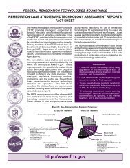
Table 1. Summary of <strong>In</strong> <strong>Situ</strong> <strong>Treatment</strong> <strong>Technologies</strong> Applications <strong>for</strong> Contaminant Classes<br />
Key: Better Average Worse<br />
S=Specific to chemical type<br />
Nonhalogenated VOCs<br />
Halogenated VOCs<br />
<strong>In</strong> <strong>Situ</strong> Physical/Chemical<br />
<strong>Soil</strong> Vapor Extraction <br />
Solidification/Stabilization <br />
Chemical Oxidation S <br />
<strong>Soil</strong> Flushing <br />
Electrokinetic Separation <br />
<strong>In</strong> <strong>Situ</strong> Biological <strong>Treatment</strong><br />
Bioremediation S S S <br />
Bioventing <br />
Phytoremediation S <br />
<strong>In</strong> <strong>Situ</strong> Thermal<br />
Thermal <strong>Treatment</strong> (electrical resistivity heating, steam<br />
injection and extraction. conductive heating, radiofrequency<br />
heating, and in situ vitrification)<br />
Nonhalogenated SVOCs<br />
Halogenated SVOCs<br />
Fuels<br />
<strong>In</strong>organics<br />
Radionuclides 1<br />
Explosives<br />
<br />
Adapted from Federal Remediation <strong>Technologies</strong> Roundtable Remediation Screening Matrix, Table 3.2.<br />
http://www.frtr.gov/matrix2/section3/table3_2.html<br />
1 For more in<strong>for</strong>mation on radionuclide technologies see: U.S. EPA.1996. Technology Screening Guide <strong>for</strong><br />
Radioactively <strong>Contaminated</strong> Sites, EPA/402/R-96/017.<br />
http://www.epa.gov/superfund/resources/radiation/pdf/techguide.pdf<br />
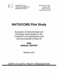
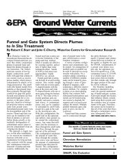
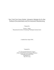
to the surface <strong>for</strong> treatment. The configuration of the<br />
system usually involves attaching blowers to extraction<br />
wells which are generally constructed with<br />
slotted polyvinyl chloride (PVC) to induce airflow<br />
through the soil matrix (Army Corps of Engineers<br />
[USACE] 2002). The contaminated air is brought to<br />
the surface and passed through a vapor/liquid<br />
separator to remove any moisture be<strong>for</strong>e the air is<br />
treated. <strong>Treatment</strong> is typically done by adsorption<br />
(activated carbon), or <strong>for</strong> more concentrated waste<br />
streams, by thermal oxidation systems (U.S. EPA<br />
2006). The water generated by the liquid separator<br />
may also require treatment (Figure 1). When expected<br />
concentrations in the air stream are sufficiently high<br />
(1,000 to 5,000 parts per million [ppm] or more) <strong>for</strong><br />
free product recovery <strong>for</strong> recycling, a stand alone<br />
condensation treatment system might be considered.<br />
3<br />
This type of system is generally not used <strong>for</strong><br />
mixtures of chemicals, and at some point the<br />
condenser system will need to be changed out when<br />
concentrations drop (USACE 2002).<br />
Concrete, asphalt, geomembrane, or other lowpermeability<br />
covers are often placed over the soil<br />
surface to prevent short-circuiting of air flow and to<br />
increase the radius of influence of the extraction<br />
wells. Replacement air can be introduced into the<br />
subsurface by injecting air via a blower or by allowing<br />
air to flow into passive injection wells.<br />
While vertical wells are the most widely used SVE<br />
design method, when the contamination and/or the<br />
water table is shallow, horizontal wells or trenches<br />
provide better lateral flow and superior <strong>for</strong>mation<br />
access.
The SVE process is driven by the partitioning of<br />
volatile materials from condensed phases (sorbed on<br />
soil particles, dissolved in pore water, or nonaqueous<br />
liquid) into the soil gas being drawn through the subsurface.<br />
The partitioning is controlled by contaminant<br />
and soil properties. These properties include<br />
contaminant vapor pressure,<br />
Henry’s law constant,<br />
solubility, soil intrinsic<br />
permeability, water<br />
content (which<br />
should be low, but very<br />
dry soils also inhibit<br />
contaminant mobilization),<br />
and organic carbon<br />
content (Air Force<br />
Center <strong>for</strong> Environmental<br />
Excellence<br />
[AFCEE ] 2002). SVE is<br />
best suited in welldrained,high-permeability<br />
soil (sand and<br />
gravel) with a low organic<br />
carbon content.<br />
Low permeability soil or<br />
heterogenous soil with<br />
high carbon content are<br />
more difficult to treat<br />
with SVE and often<br />
require amendments,<br />
such as pneumatic or<br />
hydraulic fracturing. 1<br />
Fracturing allows <strong>for</strong><br />
high preferential flow Figure 1. Typical <strong>Soil</strong> Vapor Extraction System<br />
paths, but the bulk of the<br />
contaminant load still depends upon low flow or<br />
diffusion from the competent soil matrix.<br />
Like fracturing, heterogenous subsurfaces provide<br />
differential flow paths that result in efficient removal<br />
of contaminants in the permeable layers, with the less<br />
permeable layers being subject to slow diffusive<br />
<strong>for</strong>ces. Rate-limited diffusion in the less permeable<br />
soils extends the time needed <strong>for</strong> remediation;<br />
there<strong>for</strong>e, it may be more efficient to approach these<br />
types of sites with a pulsed pumping strategy, in<br />
which the blowers are turned off at predetermined<br />
effluent concentrations, and the contaminants are<br />
allowed to diffuse into the “clean” permeable layers.<br />
1 Fracturing is the creation of cracks or sand-filled fissures in<br />
low- permeability <strong>for</strong>mations.<br />
4<br />
After a suitable (site-specific) time, the blowers are<br />
turned back on to capture the more concentrated soil<br />
vapors (AFCEE 2002). If appropriate, this method<br />
can save money on electricity and other costs. For<br />
other examples of energy conservation, see Gill and<br />
Mahutova (2004).<br />
When designing an SVE system, DiGiulio and<br />
Varadhan (2001) advise care in choosing standard<br />
radius of influence (ROI) methods to place extraction<br />
wells. These methods generally rely on measuring<br />
vacuum differentials with distance from the<br />
venting well. Vacuum measurements can indicate<br />
the direction of a flow gradient, but as the vacuum<br />
measured approaches ambient pressures, they may<br />
give a false indication and lead to placing wells too<br />
far apart. <strong>In</strong> addition, vacuum measurements give no<br />
in<strong>for</strong>mation on the effective gas flow through the<br />
various subsurface materials. For example, one-dimensional<br />
measurements made on layers of sand and<br />
silty clay will yield equivalent vacuums, while the<br />
effective gas flow is through the sand, with little<br />
going through the silty clay. A more relevant approach<br />
to well layout is to achieve a pore velocity
that exceeds some minimum rate everywhere within<br />
the contaminated zone (USACE 2002).<br />
As the vapor extraction system continues to operate,<br />
effluent contaminant concentrations generally become<br />
asymptotic (steady-state removal of very low<br />
concentrations). Unless the SVE system is addressing<br />
a single contaminant species, measurements of the<br />
venting effluent should provide the total mass being<br />
removed as well as relative compound concentrations.<br />
Speciation data also help in evaluating the<br />
system’s efficiency. Because the chemicals in a mixture<br />
have different chemical/physical properties, they<br />
will leave the mixture at different rates; hence, a drop<br />
in total concentration does not necessarily mean a<br />
drop in available contaminant or system efficiency,<br />
but rather exhaustion of certain species. It is also<br />
important to test each extraction well in the system<br />
individually to determine if the drop is occurring<br />
across all wells (USACE 2002). Testing of the header<br />
alone may mask wells that have low flow and high<br />
concentrations that are being diluted by other wells in<br />
the system.<br />
Maintaining asymptotic levels over a period of many<br />
months is often interpreted as a sign that the SVE<br />
ef<strong>for</strong>t has been successful and should be shut down;<br />
however, as USACE (2002) states: “although the<br />
decrease of concentrations in the extracted vapor is an<br />
indication of the effectiveness of the system, it is<br />
certainly not conclusive evidence that the concentrations<br />
in the soil have decreased proportionally.”<br />
Reasons <strong>for</strong> a decrease in contaminant concentration,<br />
other than reaching cleanup goals, include:<br />
• The system has exhausted the supply of contaminants<br />
that it can advectively reach, and their<br />
continued presence, at very low concentrations,<br />
represents a draw upon diffusion rate-limited<br />
source areas.<br />
• The water table has risen and the source areas are<br />
no longer available to the SVE system.<br />
• The soil has reached a dryness factor that hinders,<br />
rather than promotes, SVE.<br />
• The measured flow represents dilution from fully<br />
flushed areas near the extraction well, while<br />
understating considerably more contaminated<br />
areas further away, near stagnation points<br />
(AFCEE 2002 and DiGiulio and Varadhan 2001).<br />
5<br />
If no rebound is found after shutting the system<br />
down <strong>for</strong> a site-specific determined time, then<br />
confirmation sampling should be done. Confirmation<br />
sampling can be accomplished with an<br />
extensive soil gas survey, continuous soil sampling<br />
on a statistically determined grid, or professional<br />
judgment with sufficient previous characterization<br />
in<strong>for</strong>mation gained by use of direct push tools, such<br />
as the membrane interface probe or, in the presence<br />
of hydrocarbons, by laser-induced fluorescence<br />
spectroscopy.<br />
If a site has contaminated groundwater, it should be<br />
addressed along with the vadose zone contamination.<br />
Often this can be accomplished using a<br />
multi-phase extraction (MPE) system to simultaneously<br />
remove contaminants from soil and extract<br />
contaminated groundwater. A discussion of MPE,<br />
which is not within the scope of this document, can<br />
be found in U.S. EPA (1999) and USACE (1999).<br />
The cost of SVE is site-specific and depends in part<br />
on the hydrogeology, type and amount of contaminants,<br />
and whether the offgas requires treatment.<br />
The FRTR website estimates the cost is between $10<br />
and $40 per cubic yard, with a typical pilot program<br />
costing between $10,000 and $40,000. The<br />
NAVFAC website provides a $20 to $60 per cubic<br />
yard estimate. USACE (2002) provides a strategy<br />
<strong>for</strong> estimating costs and a checklist <strong>for</strong> items to<br />
include in the estimate. SVE is a mature, widely<br />
used technology, and many vendors are capable of<br />
implementing the technology.<br />
Cited and Other References<br />
AFCEE. 2000. Source Reduction Effectiveness at<br />
Fuel-<strong>Contaminated</strong> Sites: Technical Summary Report.<br />
125 pp. http://www.afcee.brooks.af.mil/pro<br />
ducts/techtrans/download/SourceRed.pdf<br />
American Academy of Environmental Engineers.<br />
1998. <strong>In</strong>novative Site Remediation Technology<br />
Design & Application, Volume 7: Vacuum Extraction<br />
and Air Sparging, EPA 542/B-97/010. U.S.<br />
EPA, Office of Solid Waste and Emergency Response,<br />
392 pp. http://nepis.epa.gov/pubtitleOSW<br />
ER.htm<br />
DiGiulio, D. and R. Varadhan. 2001. Development<br />
of Recommendations and Methods to Support<br />
Assessment of <strong>Soil</strong> Venting Per<strong>for</strong>mance and<br />
Closure, EPA 600/R-01/070. U.S. EPA Office of
Research and Development, 435 pp. http://www.epa.<br />
gov/ada/pubs/reports.html<br />
FRTR website at: http://www.frtr.gov/<br />
Gill, M. and K. Mahutova. 2004. Engineering Forum<br />
Issue Paper: <strong>In</strong>troduction to Energy Conservation and<br />
Production at Waste Cleanup Sites, EPA 542/<br />
S-04/001. U.S. EPA, Office of Solid Waste and<br />
Emergency Response, 36 pp. http://www.epa.gov/<br />
tio/tsp/download/epa542s04001.pdf<br />
Johnson, R., R. Dupont, and D. Graves. 1996.<br />
Assessing UST Corrective Action <strong>Technologies</strong>:<br />
Diagnostic Evaluation of <strong>In</strong> <strong>Situ</strong> SVE-Based System<br />
Per<strong>for</strong>mance, EPA 600/R-96/041. U.S. EPA, Office<br />
of Research and Development, 162 pp. http://nepis.<br />
epa.gov/pubtitleORD.htm<br />
NAVFAC. 2006. Naval Engineering Facilities<br />
Environmental Restoration & BRAC website.<br />
https://portal.navfac.navy.mil/portal/page?_pageid=<br />
181,5346904&_dad=portal&_schema=PORTAL<br />
USACE. 1999. Engineering and Design: Multi-Phase<br />
Extraction, EM 1110-1-4010, 286 pp. http://www.<br />
usace.army.mil/publications/eng-manuals/em1110<br />
1-4010/toc.htm<br />
USACE. 2002. Engineering and Design: <strong>Soil</strong> Vapor<br />
Extraction and Bioventing, EM 1110-1-4001, 424 pp.<br />
http://www.usace.army.mil/inet/usace-docs/engmanuals/em1110-1-4001/toc.htm<br />
USACE. 2006. Army Corps of Engineers Environmental<br />
webpage. http://www.environmental.usace.<br />
army.mil/<br />
U.S. EPA. 1997a. Analysis of Selected Enhancements<br />
<strong>for</strong> <strong>Soil</strong> Vapor Extraction, EPA 542/R-97/007.<br />
Office of Solid Waste and Emergency Response, 246<br />
pp. http://www.cluin.org/download/remed/sveen<br />
hmt.pdf<br />
U.S. EPA. 1997b. Michigan <strong>Soil</strong> Vapor Extraction<br />
Remediation (MISER) Model: A Computer Program<br />
to Model <strong>Soil</strong> Vapor Extraction and Bioventing of<br />
Organic Chemicals in Unsaturated Geological<br />
Material, EPA 600/R-97/099. Office of Research and<br />
Development, 260 pp. http://nepis.epa.gov/pubtitle<br />
ORD.htm<br />
6<br />
U.S. EPA. 1999. Multi-Phase Extraction: State-ofthe-Practice,<br />
EPA 542/R-99/004. Office of Solid<br />
Waste and Emergency Response, 78 pp. http://<br />
www.epa.gov/tio/download/remed/mpe2.pdf<br />
U.S. EPA. 2006. Off-Gas <strong>Treatment</strong> <strong>for</strong> <strong>Soil</strong> Vapor<br />
Extraction Systems: State of the Practice, EPA<br />
542/R-05/028. Office of Solid Waste and<br />
Emergency Response, 129 pp. http://www.cluin.<br />
org/download/remed/EPA542R05028.pdf<br />
3.1.2 Solidification/Stabilization<br />
Solidification and stabilization (S/S) refer to closely<br />
related technologies that use chemical and/or<br />
physical processes to treat radioactive, hazardous,<br />
and mixed wastes. Solidification technologies encapsulate<br />
the waste to <strong>for</strong>m a solid material. The<br />
product of solidification may be a monolithic block,<br />
a clay-like material, a granular particulate, or some<br />
other physical <strong>for</strong>m commonly considered “solid.”<br />
Stabilization technologies reduce the hazard potential<br />
of a waste by converting the contaminants into<br />
less soluble, mobile, or toxic <strong>for</strong>ms (e.g., Cr(VI) to<br />
Cr(III)). The physical nature and handling characteristics<br />
of the waste are not necessarily changed<br />
by stabilization.<br />
Chemical stabilization relies on the reduction of<br />
contaminant mobility by physical or chemical reactions<br />
with the contaminant, rather than the contaminant<br />
matrix (e.g., soil or sediment), as is done with<br />
solidification. The mobility of organic and inorganic<br />
compounds can be reduced through various precipitation,<br />
complexation, and adsorption reactions.<br />
Commonly applied inorganic stabilization agents<br />
include soluble silicates, carbon, phosphates (e.g.,<br />
apatite), and sulfur-based binders. Organo-clays<br />
have been used to stabilize organic chemicals that<br />
are poorly addressed by precipitation and complexation<br />
reactions (U.S. EPA 1997).<br />
The S/S process can be accomplished using either<br />
inorganic or polymer binders. The most common<br />
inorganic binders are Portland cement, pozzolans<br />
(siliceous or aluminous materials that can react with<br />
calcium hydroxide to <strong>for</strong>m compounds with cementitious<br />
properties), and cement/pozzolan mixtures.<br />
While these binders are effective <strong>for</strong> a range of<br />
inorganic cations and anions, a treatability study
should be conducted using on-site soil, contaminants,<br />
and groundwater (if applicable).<br />
<strong>In</strong> situ chemical stabilization of inorganics using<br />
phosphorus based and other compounds was<br />
evaluated in September 1998 under EPA’s Superfund<br />
<strong>In</strong>novative Technology Evaluation Program (SITE).<br />
The <strong>Soil</strong> Rescue and Envirobond remediation<br />
products were applied to a small area of leadcontaminated<br />
soil at the Crooksville/Roseville Pottery<br />
site in southeastern Ohio. These products chelate the<br />
metal ions to reduce mobility. The mean Toxicity<br />
Characteristic Leaching Procedure (TCLP) lead<br />
concentrations were reduced by more than 99 percent<br />
<strong>for</strong> both products (U.S. EPA 2002 and 2003).<br />
S/S treatment of organic contaminants with<br />
cementitious <strong>for</strong>mulations is more complex than<br />
treatment of inorganic contaminants. While low<br />
levels of organic contaminants can<br />
be treated using S/S, many organics<br />
will interfere with the hydration<br />
process and impede the curing of<br />
the solid (U.S. EPA 1997).<br />
Subsurface variations in the concentrations<br />
of organics can affect<br />
both the leachability and final<br />
physical properties of the treated<br />
wastes or soil. Thorburg et al.<br />
(2005) used Portland cement to<br />
treat a sediment contaminated with<br />
coal tar-derived hydrocarbons. The<br />
results showed that the treated<br />
sediments leached polycyclic aromatic<br />
hydrocarbons (PAHs) and<br />
midrange aromatic and aliphatic<br />
hydrocarbons at concentrations<br />
well above their effective solu-<br />
The most significant challenge in applying S/S in situ<br />
<strong>for</strong> contaminated soils is achieving complete and<br />
uni<strong>for</strong>m mixing of the binder with the contaminated<br />
matrix. Three basic approaches are used <strong>for</strong> mixing<br />
the binder with the matrix:<br />
• Vertical auger mixing<br />
• Shallow in-place mixing<br />
• <strong>In</strong>jection grouting<br />
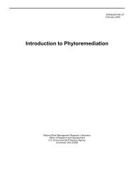
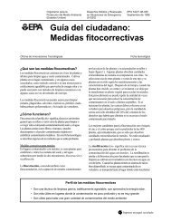
Vertical auger mixing requires a system of augers to<br />
inject and mix binder into the soil (Figure 2). The<br />
treatment depth is limited by the torque required to<br />
turn the auger. Current testing indicates a limit of<br />
depths to less than 150 feet. The auger diameter,<br />
which determines the number of holes that need to<br />
be drilled <strong>for</strong> a given areal extent, can range from<br />
several meters <strong>for</strong> shallow mixing to much smaller<br />
diameters <strong>for</strong> deep mixing. The need <strong>for</strong> a smaller<br />
diameter auger means more holes will need to be<br />
drilled per unit area, which increases the cost <strong>for</strong> the<br />
deeper mixing. If VOCs or mercury are present at<br />
the site, the contaminant vapors should be captured<br />
and treated. The capture is usually accomplished<br />
with a hood that covers the mixing area and conveys<br />
the gases to an on-site treatment system. Auger<br />
mixing is the most commonly applied method <strong>for</strong> in<br />
situ mixing of S/S reagents with soil.<br />
Figure 2. MecTool <strong>for</strong> Solidification and Stabilization of<br />
bilities. Most cementitious pro- <strong>Contaminated</strong> <strong>Soil</strong>s and Sludges<br />
cesses are exothermic, and the heat<br />
generated by the curing process has the potential to <strong>In</strong>-place mixing involves the spreading and mixing<br />
volatilize VOCs.<br />
of binder reagents with waste by conventional earthmoving<br />
equipment, such as draglines, backhoes, or<br />
clamshell buckets. A large auger rig can also be<br />
employed <strong>for</strong> in-place mixing. The technology is<br />
applicable only to surface or shallow deposits of<br />
contamination.<br />
7<br />
A novel <strong>for</strong>m of in-place waste mixing can be used<br />
<strong>for</strong> large areas of heavy-metals contaminated soil. A<br />
lime-stabilized biosolid can be plowed into the<br />
contaminated soil, yielding a mixture that reduces<br />
toxicity and bioavailability of the heavy metals
while providing a soil suitable <strong>for</strong> supporting<br />
vegetation.<br />
<strong>In</strong>jection grouting involves <strong>for</strong>cing a binder containing<br />
dissolved or suspended treatment agents into<br />
the <strong>for</strong>mation under pressure, thereby permeating the<br />
soil. Grout injection may be applied to contaminated<br />
<strong>for</strong>mations lying well below the ground surface. The<br />
injected grout cures in place, producing an in situ<br />
treated mass.<br />
Polymer binders are thermoplastic or thermosetting.<br />
Thermoplastic binders are materials that can be repeatedly<br />
melted to a flow state and will harden when<br />
cooled. Polyethylene, sulfur polymer, and bitumen<br />
are examples of theromoplastic binders. Thermosetting<br />
binders are materials that require the combination<br />
of several liquid ingredients (e.g., monomer,<br />
catalyst, promoter) that, when combined, harden to a<br />
solid that cannot be reworked (U.S. EPA 1997).<br />
Thermoplastic binders operate in a temperature range<br />
of 120 to 180 o C, which could be an issue in soil with<br />
high moisture content. Thermosetting binders operate<br />
at ambient temperatures, but they are not amenable to<br />
high moisture content. While polymer binders are<br />
effective, they may be difficult to use in an in situ<br />
setting.<br />
S/S has been applied to the remediation of hazardous<br />
waste sites <strong>for</strong> more than 15 years. Experience with<br />
the technology, especially the inorganic binders<br />
(Portland cement and pozzolans), is abundant.<br />
The Army Environmental Policy <strong>In</strong>stitute (1998)<br />
estimates that in situ S/S of metals using a phosphoric<br />
apatite binder costs approximately $46 per ton;<br />
using Portland cement <strong>for</strong> metals costs about $125<br />
per ton; using ammonium modified Portland cement<br />
<strong>for</strong> organics costs about $101 per ton; and using<br />
polyethylene costs about $609 per ton. The Portland<br />
Cement Association also has costing data:<br />
http://www.cement.org/.<br />
Cited and Other References<br />
Army Environmental Policy <strong>In</strong>stitute. 1998.<br />
Solidification <strong>Technologies</strong> <strong>for</strong> Restoration of Sites<br />
<strong>Contaminated</strong> with Hazardous Wastes, 80 pp.<br />
http://www.aepi.army.mil/pubs-cleanup.html<br />
Maher, A., H. Najm, and M. Boile. 2005. Solidification/Stabilization<br />
of Soft River Sediments Using<br />
Deep <strong>Soil</strong> Mixing. State of New Jersey Department<br />
8<br />
of Transportation, 44 pp. http://www.state.nj.us/<br />
transportation/works/maritime/documents/deep<br />
soilmixingfinal.pdf<br />
Portland Cement Association. 2006 (November).<br />
Portland Cement Association webpage. http://www.<br />
cement.org/waste/wt_tech_epapubs.asp<br />
Thornburg, T. et al. 2005. Effectiveness of in situ<br />
cement stabilization <strong>for</strong> remediation of sediment<br />
containing coal tar derived hydrocarbons. The Annual<br />
<strong>In</strong>ternational Conference on <strong>Contaminated</strong><br />
<strong>Soil</strong>s, Sediments, and Water, October 17-20, 2005,<br />
University of Massachusetts, Amherst. http://www.<br />
umasssoils.com/abstracts2005/Thursday/evolving<br />
%20strategies.htm<br />
USACE. 2006. Unified Facilities Guide Specifications:<br />
Section 02 55 00, Solidification/Stabilization<br />
(S/S) of <strong>Contaminated</strong> Material, UFGS-02 55 00, 16<br />
pp. http://www.wbdg.org/ccb/DOD/UFGS/UFGS%<br />
2002%2055%2000.pdf<br />
U.S. EPA. 1993a. Engineering Bulletin: Solidification/Stabilization<br />
of Organics and <strong>In</strong>organics,<br />
EPA 540/S-92/015. Office of Emergency and Remedial<br />
Response, 13 pp. http://www.cement.org/waste<br />
/wt_tech_epapubs.asp<br />
U.S. EPA. 1993b. Technical Resource Document:<br />
Solidification/Stabilization and Its Application to<br />
Waste Materials, EPA 530/R-93/012. Office of<br />
Research and Development, 372 pp. http://www.<br />
cement.org/waste/wt_tech_epapubs.asp<br />
U.S. EPA. 1996. Technology Screening Guide <strong>for</strong><br />
Radioactively <strong>Contaminated</strong> Sites, EPA 402/R-96<br />
/017. Office of Radiation and Office of Solid Waste<br />
and Emergency Response, 203 pp. http://www.epa.<br />
gov/superfund/resources/radiation/pdf/techguide.pdf<br />
U.S. EPA. 1997. <strong>In</strong>novative Site Remediation<br />
Design and Application, Volume 4: Stabilization/<br />
Solidification, EPA 542/B-97/007. Office of Solid<br />
Waste and Emergency Response, 234 pp.<br />
http://nepis.epa.gov/pubtitleOSWER.htm<br />
U.S. EPA. 1998. MOLECULAR BOND<strong>IN</strong>G<br />
SYSTEM ® <strong>In</strong>novative Technology Evaluation Report,<br />
EPA 540/R-97/507. Office of Research and<br />
Development, 56 pp. http://www.epa.gov/ORD/<br />
SITE/reports/540r97507/540r97507.pdf
U.S. EPA. 1999. Solidification/Stabilization Resource<br />
Guide, EPA 542/B-99/002. Office of Solid<br />
Waste and Emergency Response, 91 pp. http://www.<br />
clu-in.org/download/remed/solidstab.pdf<br />
U.S. EPA. 2000. Solidification/Stabilization Use at<br />
Superfund Sites, EPA 542/R-00/010. Office of Solid<br />
Waste and Emergency Response, 24 pp. http://www.<br />
clu-in.org/s.focus/c/pub/i/611/<br />
U.S. EPA. 2002. Superfund <strong>In</strong>novative Technology<br />
Evaluation Program: Evaluation of <strong>Soil</strong> Amendment<br />
<strong>Technologies</strong> at the Crooksville/Roseville Pottery<br />
Area of Concern, Rocky Mountain Remediation Services<br />
Envirobond TM Process. Office of Research and<br />
Development, 16 pp. http://www.epa.gov/ORD/<br />
NRMRL/pubs/540r02501/540R02501.pdf<br />
U.S. EPA. 2003. Evaluation of <strong>Soil</strong> Amendment<br />
<strong>Technologies</strong> at the Crooksville/Roseville Pottery<br />
Area of Concern STAR Organics <strong>Soil</strong> Rescue:<br />
<strong>In</strong>novative Technology Evaluation Report, EPA<br />
540/R-99/501. Office of Research and Development,<br />
14 pp. http://www.epa.gov/ORD/SITE/reports/540<br />
r99501/540R99501prel.pdf<br />
U.S. EPA. 2004. <strong>In</strong>novative Technology Evaluation<br />
Report: Stabilization of Mercury in Waste Material<br />
from the Sulfur Bank Mercury Mine. Office of<br />
Research and Development, 68 pp. http://www.epa.<br />
gov/ORD/NRMRL/pubs/540r04502/540r04502.pdf<br />
3.1.3 Chemical Oxidation<br />
Chemical oxidation typically involves reduction/<br />
oxidation (redox) reactions that chemically convert<br />
hazardous contaminants to nonhazardous or less toxic<br />
compounds that are more stable, less mobile, or inert.<br />
Redox reactions involve the transfer of electrons from<br />
one chemical to another. Specifically, one reactant is<br />
oxidized (loses electrons) and one is reduced (gains<br />
electrons). There are several oxidants capable of<br />
degrading contaminants. Commonly used oxidants<br />
include potassium or sodium permanganate, Fenton’s<br />
catalyzed hydrogen peroxide, hydrogen peroxide,<br />
ozone, and sodium persulfate. Each oxidant has<br />
advantages and limitations, and while applicable to<br />
soil contamination and some source zone<br />
contamination, they have been applied primarily<br />
toward remediating groundwater. Several key<br />
concepts in oxidant selection <strong>for</strong> site cleanup include:<br />
9<br />
• Is the oxidant capable of degrading the contaminant<br />
of concern? Is a catalyst or other additive<br />
required to increase effectiveness?<br />
• What is the soil oxidant demand (SOD)? SOD is<br />
a measure of how the naturally occurring materials<br />
in soil will affect the per<strong>for</strong>mance of<br />
some of the oxidants. For non-selective oxidants,<br />
high SOD will increase the cost of cleanup,<br />
as more oxidant will be required.<br />
• What is the naturally occurring pH of the soil/<br />
groundwater system? Some oxidants require an<br />
acidic environment to work. If the soil is basic,<br />
an acid needs to be applied in addition to the<br />
oxidant.<br />
• How will the decomposition rate of the oxidant<br />
affect application strategies? Some unreacted<br />
oxidants may remain in the subsurface <strong>for</strong><br />
weeks to months, while others naturally decompose<br />
within hours of injection.<br />
The type of delivery system selected depends upon<br />
the depth of the contaminants, the physical state of<br />
the oxidant (gas, liquid, solid), and its decomposition<br />
rate. Backhoes, trenchers, and augers have<br />
been used to work liquid and solid oxidants into<br />
contaminated soil and sludge. Liquids can be<br />
delivered either by gravity through wells and<br />
trenches or by injection. For vadose zones, gravity<br />
has the drawback of a relatively small area of<br />
influence. Pressurized injection of liquids or gases,<br />
either through the screen of a well or the probe of a<br />
direct push (DP) rig, will <strong>for</strong>ce the oxidant into the<br />
<strong>for</strong>mation. The DP rig offers a cost-effective way of<br />
delivering the oxidant, and if needed, the hole can be<br />
completed as a small diameter well <strong>for</strong> later<br />
injections. Potassium permanganate and other solid<br />
phase chemical oxidants have also been added by<br />
hydraulic or pneumatic fracturing.<br />
The site stratigraphy plays an important role in the<br />
distribution of oxidants. Fine-grained units redirect<br />
oxidants to more permeable areas and are difficult to<br />
penetrate; hence, they can be the source of rebound<br />
later on, as contaminants diffuse out. Long-lived<br />
oxidants (e.g., permanganate) have the potential to<br />
remain active as this diffusion occurs, and they can<br />
mitigate some of the potential rebound.
Chemical oxidation usually requires multiple applications.<br />
Table 2 provides a qualitative list of oxidant<br />
reactivities with contaminants commonly found at<br />
sites.<br />
<strong>In</strong> the special case of nonaqueous phase liquids,<br />
oxidants that are in a water-based solution will only<br />
be able to react with the dissolved phase of the contaminant,<br />
since the two will not mix. This property<br />
limits their activity to the oxidant solution/NAPL<br />
interface.<br />
Cost estimates depend on the heterogeneity of the site<br />
subsurface, soil oxidation demand, stability of the<br />
oxidant, and type and concentration of the<br />
contaminant. Care should be taken when comparing<br />
different technologies on a cubic yard basis without<br />
considering these site attributes. Cost data can be<br />
found in ITRC (2005) and Brown (2003). <strong>In</strong> situ<br />
chemical oxidation has been used at a number of sites<br />
and is available from a variety of vendors.<br />
Sodium or Potassium Permanganate. Permanganate<br />
is a non-specific oxidizer of contaminants with low<br />
standard oxidation potential and high SOD. It can be<br />
used over a wide range of pH values and does not<br />
require a catalyst. Permanganate tends to remain in<br />
the subsurface <strong>for</strong> a long time, allowing <strong>for</strong> more<br />
contaminant contact and the potential of reducing<br />
rebound. As permanganate oxidizes organic<br />
materials, manganese oxide (MnO 2) <strong>for</strong>ms as a dark<br />
brown to black precipitate. During the treatment of<br />
large bodies of NAPL with high concentrations of<br />
permanganate, this precipitate may <strong>for</strong>m a coating<br />
that reduces contact between oxidant and NAPL.<br />
The extent to which this reduction negatively<br />
impacts contaminant oxidation has not been<br />
quantified. Potassium permanganate has a much<br />
lower solubility than sodium and is generally<br />
applied at lower concentrations. Commercial-grade<br />
permanganates may contain elevated concentrations<br />
of heavy metals, and they may lower the pH of the<br />
treated zone (U.S. EPA 2004). If bioremediation is<br />
planned as a polishing step, permanganate will have<br />
an adverse effect on microbial activity and may<br />
cause a change in microbe distribution. This effect<br />
is generally transitory. Also, there is some evidence<br />
that permanganates may be inhibitory to Dehalococcoides<br />
ethenogenes, the microbial species that<br />
completely dechlorinates tetrachloroethene (PCE)<br />
and trichloroethene (TCE) (Hrapovic et al. 2005).<br />
Fenton’s Catalyzed Hydrogen Peroxide. Fenton’s<br />
reagent uses hydrogen peroxide in the presence of<br />
ferrous sulfate to generate hydroxyl radicals that are<br />
powerful oxidants. The reaction is fast, releases<br />
oxygen and heat, and can be difficult to control.<br />
Because of the fast reaction, the area of influence<br />
around the injection point is small. <strong>In</strong> conventional<br />
Table 2. Reactivity of Oxidants with Commonly Found Contaminants 1<br />
Oxidant High Moderate Low<br />
Ozone PCE, TCE, DCE, VC, MTBE,<br />
CB, PAHs, Phenols, Explosives,<br />
PCBs, Pesticides<br />
BTEX, CH2Cl2, CT, CHCl3, Hydrogen Peroxide2 PCE, TCE, DCE, VC, CB,<br />
BTEX, MTBE, Phenols<br />
DCA, CH2Cl2, PAHs,<br />
Explosives<br />
TCA, CT, CHCl3, PCBs, Pesticides<br />
Calcium Peroxide PCE, TCE, DCE, VC, CB DCA, CH2Cl2 CT, CHCl3 Fenton’s Reagent PCE, TCE, DCE, VC, CB,<br />
BTEX, MTBE, Phenols<br />
DCA, CH2Cl2, PAHs,<br />
Explosives<br />
TCA, CT, CHCl3, PCBs, Pesticides<br />
Potassium/Sodium PCE, TCE, DCE, VC, TEX, Pesticides Benzene, DCA,<br />
Permanganate PAHs, Phenols, Explosives<br />
CH2Cl2, TCA, CT, CB,<br />
CHCl3, PCBs<br />
Sodium Persulfate<br />
(Iron)<br />
PCE, TCE, DCE, VC, CB,<br />
BTEX, Phenols<br />
DCA, CH2Cl2, CHCl3, PAHs, Explosives,<br />
Pesticides<br />
TCA, CT, PCBs<br />
Sodium Persulfate All CVOCs, BTEX, MTBE,<br />
(Heat)<br />
PAHs, Phenols, Explosives,<br />
PCBs, Pesticides<br />
Source: ITRC 2005 and Brown 2003<br />
1 Contaminant names are spelled out in the abbreviations and acronyms list in Section 5.0.<br />
2<br />
Peroxide without a catalyst must be applied at higher concentrations, which are inherently hazardous, and the reactions are<br />
10
application, the reaction needs to take place in an<br />
acidified environment, which generally requires the<br />
injection of an acid to lower the treatment zone pH to<br />
between three and five. The reaction oxidizes the<br />
ferrous iron to ferric iron and causes it to precipitate,<br />
which can result in a loss of permeability in the soil<br />
near the injection point. Over time, the depletion of<br />
the ferrous ion can be rate limiting <strong>for</strong> the process.<br />
Chelated iron can be used to preserve the iron in its<br />
ferrous state at neutral pH, thus eliminating the acid<br />
requirement. The byproducts of the reaction are relatively<br />
benign, and the heat of the reaction may cause<br />
favorable desorption or dissolution of contaminants<br />
and their subsequent destruction. It also may cause<br />
the movement of contaminants away from the treatment<br />
zone or allow them to escape to the atmosphere.<br />
There are safety concerns with handling<br />
Fenton’s reagent on the surface, and the potential<br />
exists <strong>for</strong> violent reactions in the subsurface. <strong>In</strong> many<br />
cases there may be sufficient iron or other transition<br />
metals in the subsurface to eliminate the need to add<br />
ferrous sulfate.<br />
Hydrogen Peroxide. While catalysts can be added to<br />
increase oxidation potential, hydrogen peroxide can<br />
be used alone to oxidize contaminants. Peroxide<br />
oxidation is an exothermic reaction that can generate<br />
sufficient heat to boil water. The generation of heat<br />
can assist in making contaminants more available <strong>for</strong><br />
degradation as well as allowing them to escape to the<br />
surface. With its high reaction and decomposition<br />
rates, hydrogen peroxide is not likely to address<br />
contaminants found in low permeability soil. Solid<br />
peroxides (e.g., calcium peroxide) in slurry <strong>for</strong>m<br />
moderate the rate of dissolution and peroxide<br />
generation, thereby allowing a more uni<strong>for</strong>m<br />
distribution.<br />
Ozone. Ozone, which is one of the stronger oxidants,<br />
can be applied as a gas or dissolved in water. As a<br />
gas, ozone can directly degrade a number of<br />
chemicals in both the dissolved and pure <strong>for</strong>ms, and<br />
it provides an oxygen-rich environment <strong>for</strong><br />
contaminants that degrade under aerobic conditions.<br />
It also degrades in water to <strong>for</strong>m radical species,<br />
which are highly reactive and non-specific. Ozone<br />
may require longer injection times than other<br />
oxidants, and vapor control equipment may be needed<br />
at the surface. Because of its reactivity, ozone may<br />
not be appropriate <strong>for</strong> slow diffusion into lowpermeability<br />
soil.<br />
11<br />
-2 Sodium Persulfate. Persulfate (S2O8 ) is a strong<br />
oxidant with a higher oxidation potential than<br />
hydrogen peroxide and a potentially lower SOD than<br />
permanganate or peroxide. Persulfate reaction is<br />
slow unless placed in the presence of a catalyst, such<br />
as ferrous iron, or heated to produce sulfate free<br />
- radicals (•SO4 ) that are highly reactive and capable<br />
of degrading many organic compounds. At<br />
temperatures above 40oC, persulfate becomes<br />
especially reactive and can degrade most organics<br />
(Block et al. 2004). Like Fenton’s reagent, the<br />
ferrous iron catalyst (when used) will degrade with<br />
time and precipitate.<br />
Cited and Other References<br />
Block, P., R. Brown, and D. Robinson. 2004. Novel<br />
activation technologies <strong>for</strong> sodium persulfate in situ<br />
chemical oxidation. Proceedings of the Fourth <strong>In</strong>ternational<br />
Conference on the Remediation of Chlorinated<br />
and Recalcitrant Compounds, Monterey, CA.<br />
http://www.geo-log.de/uploads/media/novel_<br />
persulfate_activation_technologies.pdf<br />
Brown, R. 2003. <strong>In</strong> situ chemical oxidation:<br />
per<strong>for</strong>mance, practice, and pitfalls. 2003 AFCEE<br />
Technology Transfer Workshop, February 25, 2003,<br />
San Antonio, TX. http://www.cluin.org/download/<br />
techfocus/chemox/4_brown.pdf<br />
Haselow, J., P. Block, and F. Sessa. 2006. Pilot scale<br />
application of heat-activated persulfate at a <strong>for</strong>mer<br />
petroleum underground storage tank area. The 22nd<br />
<strong>In</strong>ternational Conference on <strong>Soil</strong>s, Sediments, and<br />
Water, University of Massachusetts, Amherst, MA,<br />
October 16-19, 2006.<br />
Hrapovic, L. et al. 2005. Laboratory study of treatment<br />
of trichloroethene by chemical oxidation followed<br />
by bioremediation. Environ. Sci. Technol.<br />
39(8): 2888-2897.<br />
Huling, S. and B. Pivetz. 2006. Engineering Issue:<br />
<strong>In</strong> <strong>Situ</strong> Chemical Oxidation, EPA 600/R-06/072.<br />
U.S. EPA, Office of Research and Development, 60<br />
pp. http://www.epa.gov/ada/topics/oxidation_issue.<br />
html<br />
ITRC. 2005. Technical and Regulatory Guidance <strong>for</strong><br />
<strong>In</strong> <strong>Situ</strong> Chemical Oxidation of <strong>Contaminated</strong> <strong>Soil</strong><br />
and Groundwater, 2 nd Edition.172 p. http://www.itrc<br />
web.org/Documents/ISCO-2.pdf
NAVFAC. October 2006. <strong>In</strong> <strong>Situ</strong> Chemical Oxidation<br />
Multi-media Training Tool. http://www.ert2.org/ert2<br />
portal/DesktopDefault.aspx<br />
U.S. EPA. 2004. How to Evaluate Alternative<br />
Cleanup <strong>Technologies</strong> <strong>for</strong> Underground Storage Tank<br />
Sites: A Guide <strong>for</strong> Corrective Action Plan Reviewers,<br />
EPA 510/R-04/002. Office of Underground Storage<br />
Tanks. http://epa.gov/oust/pubs/tum_ch13.pdf<br />
3.1.4 <strong>Soil</strong> Flushing<br />
<strong>Soil</strong> flushing involves flooding a zone of contamination<br />
with an appropriate solution to remove the<br />
contaminant from the soil. Water or liquid solution is<br />
injected or infiltrated into the area of contamination.<br />
The contaminants are mobilized by solubilization,<br />
<strong>for</strong>mation of emulsions, or a chemical reaction with<br />
the flushing solutions. After passing through the<br />
contamination zone, the contaminant-bearing fluid is<br />
collected and brought to the surface <strong>for</strong> disposal,<br />
recirculation, or on-site treatment and reinjection.<br />
Application of soil flushing relies on the ability to<br />
deliver, control the flow, and recover the flushing<br />
fluid.<br />
Flushing solutions may be water, acidic aqueous<br />
solutions, basic solutions, chelating or complexing<br />
agents, reducing agents, cosolvents, or surfactants.<br />
Water will extract water-soluble (hydrophilic) or<br />
water-mobile constituents. Acidic solutions may be<br />
used to remove metals or basic organic materials.<br />
Basic solutions may be used <strong>for</strong> some metals, such as<br />
zinc, tin, or lead, and some phenols. Chelating,<br />
complexing, and reducing agents may be used to<br />
recover some metals. Cosolvents are usually miscible<br />
and are effective <strong>for</strong> some organics. Surfactants can<br />
assist in the removal of hydrophobic organics (U.S.<br />
EPA 1991).<br />
The techniques employed the most in soil flushing are<br />
surfactant and cosolvent flooding <strong>for</strong> fuels and<br />
chlorinated solvents. There are many types of<br />
surfactants (cationic, anionic, nonionic), and while<br />
adjustments can be made in the fluid composition,<br />
anionic or nonionic surfactants are generally used.<br />
This is because their negative or neutral charge<br />
reduces the possibility of their sorption to negatively<br />
charged clay particles. They also are generally less<br />
toxic than cationic surfactants.<br />
12<br />
Surfactants are commonly constructed with hydrophobic<br />
and hydrophilic chemical components,<br />
meaning that one end of the molecule is attracted to<br />
oil (or organic compounds) and the other to water.<br />
Surfactants chosen primarily to increase the<br />
contaminant (generally a NAPL) solubility are used<br />
in a solubilization flood. Surfactants chosen to<br />
produce ultra-low interfacial tensions are employed<br />
in a mobilization flood (Kueper et al. 1997). Mobilization<br />
flooding should only be considered when<br />
there is a high degree of certainty that the solution<br />
can be recovered, such as with a competent bedrock<br />
or capillary barrier underlying the treatment zone.<br />
A typical surfactant solution also may contain<br />
additives, such as electrolytes and a cosolvent. <strong>In</strong><br />
addition to being effective with the target contaminant,<br />
the surfactant solution also should be compatible<br />
with the site-specific soil, soil pore water,<br />
and groundwater (if applicable). A cosolvent, such<br />
as isopropanol, can be used to improve the surfactant<br />
solubility in solution and provide the surfactant/<br />
contaminant solution with an acceptable viscosity. A<br />
side effect of adding chemicals to the surfactant<br />
solution is that they need to be treated along with the<br />
contaminant at the recovery end (NAVFAC 2002).<br />
Cosolvents, usually alcohols, are chemicals that<br />
dissolve in both water and NAPL. <strong>In</strong> an alcohol<br />
flood, the alcohol may partition into both the NAPL<br />
and water phases. Partitioning affects the viscosity,<br />
density, solubility, and interfacial tension of the<br />
NAPL (Kueper et al. 1997). The physical properties<br />
of the NAPL vary with the amount of alcohol available<br />
<strong>for</strong> interaction, and whether the alcohol<br />
preferentially dissolves into the NAPL or into the<br />
water. Complete miscibility is achievable and results<br />
in a pumpable solution that, depending upon the<br />
density of the NAPL and the proportions of alcohol<br />
and water in the solution, may be more or less dense<br />
than water.<br />
Be<strong>for</strong>e implementing surfactant and/or cosolvent<br />
flushing, laboratory and bench-scale treatability<br />
testing should be done to ensure the selection of an<br />
agent(s) best suited <strong>for</strong> the contaminant and the sitespecific<br />
soil and geochemical conditions. Modeling<br />
of subsurface conditions is commonly done to<br />
ensure the best delivery system. Flushing is most<br />
efficient in relatively homogeneous and permeable<br />
(K $ 10 -3 cm/sec) soil (NAVFAC 2002). Heterogeneous<br />
soil reduces the efficiency of the flood sweep<br />
and may prevent optimum contact between the
agent(s) and the target contaminant. Flushing of<br />
relatively homogeneous but lower permeability (10 -4<br />
to 10 -5 cm/sec) units is possible, but it requires a highinduced<br />
gradient to move the agent, while greatly<br />
increasing the remediation time (NAVFAC 2002).<br />
Other soil factors that may adversely affect efficiency<br />
are high cation exchange capacity, high buffering<br />
capacity, high organic soil content, and pH.<br />
Land disposal restrictions and underground injection<br />
control regulations also may limit selection of the<br />
flushing solution. At a <strong>for</strong>mer drycleaner, ethanol was<br />
substituted <strong>for</strong> isopropanol because of regulatory<br />
concern about the toxicity and persistence of<br />
isopropanol. Most states allow in situ flushing of<br />
saturated or unsaturated soil, with a permit, if the<br />
aquifer in the area is already contaminated. When<br />
applying <strong>for</strong> a permit, all chemicals involved, including<br />
unreacted compounds and impurities, must be<br />
listed (NAVFAC 2002).<br />
An example of an alcohol flood to address PCE contamination<br />
was carried out at the <strong>for</strong>mer Sage’s Dry<br />
Cleaners in Jacksonville, FL. The depth to groundwater<br />
at the site was eight feet with the treatment<br />
zone consisting of a 24-ft by 9-ft elliptical source area<br />
at 26 to 31 ft below ground surface (bgs). About<br />
9,000 gallons of a 95 percent ethanol/5 percent water<br />
solution were injected into the target zone.<br />
Approximately 160,000 gallons of a ternary mixture<br />
of PCE/ethanol/water were treated on site to remove<br />
the PCE. The ethanol/water solution was disposed of<br />
offsite. Forty-two liters of PCE were recovered,<br />
which represented approximately 63 percent of the<br />
estimated volume (Florida Department of<br />
Environmental Protection 1998). Ethanol had an<br />
advantage in that it could be left in the ground at<br />
elevated levels while other alcohols, such as<br />
isopropanol, would have had to be contained due to<br />
their toxicity. The residual ethanol <strong>for</strong>med an organic<br />
substrate that promoted subsequent microbial<br />
reductive dechlorination of the remaining PCE. The<br />
authors of the study noted that overall cost could have<br />
been lowered had they recovered the ethanol and<br />
recycled it (Florida Department of Environmental<br />
Protection 1998).<br />
Due to its use in oil field applications, soil flushing is<br />
considered a mature technology; however, it has<br />
found limited application in the environmental arena.<br />
ITRC (2003) estimates the cost of surfactant/cosolvent<br />
flushing of a DNAPL source zone to range<br />
between $65 and $200 per cubic yard. Cost estimates<br />
13<br />
of $100 to $300 per cubic yard <strong>for</strong> flushing are<br />
given on the NAVFAC website. The variability<br />
stems from the waste type and the quantity to be<br />
treated. The NAVFAC figures do not include design<br />
and engineering costs, which can be considerable.<br />
Cost per cubic yard can be misleading, and the cost<br />
per gallon recovered or destroyed should also be<br />
evaluated.<br />
Cited and Other References<br />
Florida Department of Environmental Protection.<br />
1998. Cosolvent Flushing Pilot Test Report, Former<br />
Sage’s Dry Cleaner, 58 pp. http://clu-in.org/down<br />
load/remed/sages.pdf<br />
ITRC. 2003. Technical and Regulatory Guidance <strong>for</strong><br />
Surfactant/Cosolvent Flushing of DNAPL Source<br />
Zones. 140 pp. http://www.itrcweb.org/gd_DNA<br />
PLs.asp<br />
Kueper, B. et al. 1997. Technology Practices Manual<br />
<strong>for</strong> Surfactants and Cosolvents (TR-97-2). Advanced<br />
Applied Technology Demonstration Facility<br />
Program, Rice University. http://www.cluin.org/<br />
PRODUCTS/AATDF/Toc.htm<br />
NAVFAC. 2006. Naval Engineering Facilities<br />
Environmental Restoration & BRAC website.<br />
https://portal.navfac.navy.mil/portal/page?_pageid=<br />
181,5346904&_dad=portal&_schema=PORTAL<br />
NAVFAC. 2002. Surfactant-Enhanced Aquifer Remediation<br />
(SEAR) Design Manual, NFESC Technical<br />
Report TR-2206-ENV, 110 pp. http://enviro.<br />
nfesc.navy.mil/erb/erb_a/restoration/technologies/<br />
remed/phys_chem/sear/tr-2206-sear.pdf<br />
NAVFAC. 2003. Surfactant-Enhanced Aquifer Remediation<br />
(SEAR) Implementation Manual, NFESC<br />
Technical Report TR-2219-ENV, 54 pp. http://<br />
enviro.nfesc.navy.mil/erb/erb_a/restoration/<br />
technologies/remed/phys_chem/sear/tr-2219sear.pdf<br />
U.S. EPA. 1991. Engineering Bulletin: <strong>In</strong> <strong>Situ</strong> <strong>Soil</strong><br />
Flushing, EPA 540/2-91/021. Office of Research<br />
and Development, 7 pp. http://nepis.epa.gov/pubtitle<br />
OSWER.htm<br />
U.S. EPA. 1996. Environmental Research Brief:<br />
Surfactant-Enhanced DNAPL Remediation: Sur
factant Selection, Hydraulic Efficiency, and Economic<br />
Factors, EPA 600/S-96/002. Office of Research<br />
and Development, 15 pp. http://nepis.epa.gov/pub<br />
titleORD.htm<br />
3.1.5 Electrokinetic Separation<br />
Electrokinetic separation is an emerging technology<br />
that relies on the application of a low-intensity, direct<br />
current through the soil to separate and extract heavy<br />
metals, radionuclides, and organic contaminants from<br />
unsaturated soil, sludge, and sediment. The current is<br />
applied across electrode pairs that have been implanted<br />
in the ground on each side of the contaminated<br />
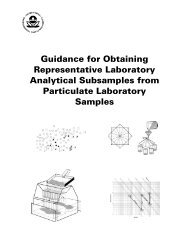
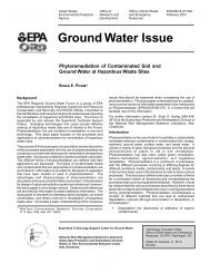
soil mass. During electromigration, positively<br />
charged chemical species, such as metals, ammonium<br />
ions, and some organic compounds, move toward the<br />
cathode, and negatively charged chemicals, such as<br />
chloride, cyanide, fluoride, nitrate, and negativelycharged<br />
organic species, migrate toward the anode<br />
(Figure 3). Electromigration does not require<br />
advective flow of pore water <strong>for</strong> the chemical species<br />
to move. <strong>In</strong> fine-grained soil, the electric current also<br />
causes electroosmosis, which is an electrically<br />
induced hydraulic flow of ground or soil pore water<br />
between the electrodes. This flow can carry neutrally<br />
charged species with it. Suspended, charged colloids<br />
and miscelles can also move by electrokinetics<br />
through the process of electrophoresis. Electrophoresis,<br />
in this instance, is similar to electromigration<br />
except that the species moving are not<br />
single molecules.<br />
Electrolysis reactions (conversion of electrical<br />
energy into chemical potential energy) create H 2 and<br />
OH - at the cathode and O 2 and H + at the anode. These<br />
reactions create an acid front near the anode and a<br />
base front near the cathode that migrate towards each<br />
other. The acid front aids in increasing the mobility<br />
of cationic species, but in some soils, it can retard<br />
electroosmois (Saichek and Reddy 2005). The hydroxide<br />
front needs to be controlled to avoid the<br />
premature precipitation of some target metal ions.<br />
This technology can be applied to contaminant concentration<br />
ranges from a few ppm to greater than<br />
10,000 ppm, but may not be effective <strong>for</strong> treating<br />
multiple contaminants that have significantly different<br />
concentrations. The target compounds are either<br />
extracted to a recovery system or deposited at the<br />
electrode. Surfactants and complexing agents may be<br />
used to increase solubility and assist in the movement<br />
of the contaminant, although care should be taken<br />
when choosing between charged (anionic/cationic)<br />
and neutral surfactants. When electroosmotic flow is<br />
from the anode to the cathode, the flow will assist<br />
cationic species and retard anionic ones (Saichek<br />
and Reddy 2005).<br />
For the electrokinetics to work, the soil moisture<br />
must be conductive and sufficient to allow electromigration<br />
but, optimally, not saturated. Removal<br />
efficiencies are directly related to the solubility of<br />
the target contaminant (which can be amended with<br />
surfactants), its electrical charge, and its concentration<br />
relative to other ions or contaminant species<br />
(Van Cauwenberghe 1997).<br />
Unfavorable conditions at a site include soil with a<br />
high cation exchange capacity, high buffering capacity,<br />
high naturally occurring organic content,<br />
salinity, and very low moisture content. The presence<br />
of subsurface metal structures or utilities can<br />
also adversely affect per<strong>for</strong>mance.<br />
Figure 3. Simple Electrokinetic Separation<br />
System<br />
14<br />
Electrokinetic separation has been demonstrated at<br />
several sites with mixed results. An independent<br />
evaluation was per<strong>for</strong>med at the Department of<br />
Energy (DOE) Sandia National Laboratories in<br />
Albuquerque, New Mexico <strong>for</strong> their patented process<br />
with Cr(VI) as the target contaminant (U.S.<br />
EPA 1999). Also, a field test was conducted by the<br />
Navy at Point Mugu with one conclusion being that<br />
there was a large discrepancy between what was<br />
expected from the bench study, which showed the<br />
technology would be very effective, versus what was<br />
actually obtained in the field, where the technology<br />
per<strong>for</strong>med poorly (ESTCP 2000).
A system that uses in situ treatment combined with<br />
electrokinetic separation is the Lasagna technique.<br />
<strong>In</strong> this system electrode arrays and treatment zones<br />
(e.g., crushed limestone, zero valent iron) are<br />
interlayered. The applied current causes the contaminants<br />
to move through the treatment zones where<br />
they are either destroyed or immobilized. Lasagna<br />
was applied with some success to treat a TCE<br />
contaminated clay soil at the DOE gaseous diffusion<br />
plant in Paducah, Kentucky (U.S. DOE 2002).<br />
Because of the limited application of electrokinetic<br />
separation, reliable cost data <strong>for</strong> full-scale applications<br />
are scarce. Costs will vary significantly depending<br />
upon the concentration of the target contaminant,<br />
presence of non-target ions, and soil characteristics<br />
and moisture content. Estimates from three<br />
vendors were collected by Van Cauwenberghe (1997)<br />
and ranged from $20 to $100 per cubic yard <strong>for</strong> one<br />
vendor to $60 to $225 per cubic yard <strong>for</strong> the high<br />
vendor estimate.<br />
Cited and Other References<br />
Alshawabkeh, A. 2001. Basics and Applications of<br />
Electrokinetic Remediation. Northeastern University,<br />
95 pp. http://www1.coe.neu.edu/~aalsha/short<br />
course.pdf<br />
Environmental Security Technology Certification<br />
Program (ESTCP). 2000. Final <strong>In</strong>-<strong>Situ</strong> Electrokinetic<br />
Remediation of Metal <strong>Contaminated</strong> <strong>Soil</strong>s<br />
Technology Status Report, SFIM-AEC-ET-CR<br />
99022. US Army Environmental Center, 30 pp, July<br />
2000. http://www.estcp.org/documents/techdocs/<br />
ISERMCS_Report.pdf<br />
NAVFAC. 2000. TechData Sheet: A Demonstration<br />
of Electrokinetic Remediation, TDS-2084-ENV, 2 pp.<br />
Roulier; M., M. Kemper; P. Cluxton. 2002.<br />
Horizontal Configuration of the Lasagna <strong>Treatment</strong><br />
Technology. User Guide, EPA 600/R-02/033.<br />
U.S. Environmental Protection Agency, Office of<br />
Research and Development, 38 pp. http://nepis.epa.<br />
gov/pubtitleORD.htm<br />
Saichek, R. and K. Reddy. 2005. Electrokinetically<br />
enhanced remediation of hydrophobic organic compounds<br />
in soils: A review. Critical Reviews in Environmental<br />
Science and Technology, 35: 115–192.<br />
http://www.uic.edu/classes/cemm/cemmlab/35-2<br />
2005.pdf<br />
15<br />
U.S. DOE. 2002. Final Remedial Action Report <strong>for</strong><br />
Lasagna TM Phase IIb <strong>In</strong>-<strong>Situ</strong> Remediation of Solid<br />
Waste Management Unit 91 at the Paducah Gaseous<br />
Diffusion Plant, Paducah, Kentucky, OR/072037<br />
&D1, 80 pp. http://www.rtdf.org/public/lasagna/<br />
lasagna_final_a.pdf<br />
U.S. EPA. 1997. Electrokinetic Laboratory and Field<br />
Processes Applicable to Radioactive and Hazardous<br />
Mixed Waste in <strong>Soil</strong> and Groundwater. EPA 402/R<br />
97/006. Office of Radiation and <strong>In</strong>door Air. July<br />
1997. http://nepis.epa.gov/pubtitleOAR.htm<br />
U.S. EPA. 1999. Sandia National Laboratories <strong>In</strong><br />
<strong>Situ</strong> Electrokinetic Extraction Technology <strong>In</strong>novative<br />
Technology Evaluation Report, EPA 540/R<br />
97/509. Office of Research and Development, 69 pp.<br />
http://www.epa.gov/ORD/SITE/reports/540r97509/<br />
540r97509.pdf<br />
Van Cauwenberghe, L. 1997. Electrokinetics. Technology<br />
Overview Report. Ground Water Remediation<br />
<strong>Technologies</strong> Analysis Center.<br />
3.2 Biological <strong>Treatment</strong> <strong>Technologies</strong><br />
Biological treatment involves the use of microorganisms<br />
or vegetation (phytoremediation). Many<br />
naturally occurring microorganisms (typically,<br />
bacteria and fungi) can trans<strong>for</strong>m hazardous chemicals<br />
to substances that may be less hazardous than<br />
the original compounds. Microrganisms also have<br />
been used to alter the valence of some hazardous<br />
metals (e.g., Cr(VI)), thereby making them less<br />
hazardous and less mobile. Several plant species<br />
have the ability to bioaccumulate heavy metals<br />
found in the soil, and some tree species can<br />
sequester, destroy, and/or evapotranspire various<br />
organic compounds.<br />
Microbial bioremediation occurs under both aerobic<br />
and anaerobic conditions and at contaminated sites<br />
as either intrinsic and/or enhanced biodegradation.<br />
<strong>In</strong>trinsic bioremediation depends on indigenous<br />
microorganisms to degrade contaminants without<br />
any amendments. Monitored natural attenuation<br />
(MNA) often relies on intrinsic bioremediation as an<br />
important removal mechanism. During enhanced<br />
bioremediation, biodegradation is facilitated by<br />
manipulating the microbial environment. Typically,<br />
the environment is manipulated by supplying<br />
amendments, such as air, organic substrates, nutrients,<br />
and other compounds, whose absence limit
treatment. <strong>In</strong> some cases, bioremediation has been<br />
enhanced by adding microbial cultures (bioaugmentation).<br />
3.2.1 Bioventing<br />
Bioventing involves the injection of a gas into the<br />
subsurface to enhance the biodegradation of a<br />
contaminant. The gas can be used to keep the subsurface<br />
aerobic or anaerobic, or to provide a substrate<br />
that enables cometabolic degradation to occur.<br />
Aerobic Bioventing<br />
Aerobic bioventing has a robust track record in<br />
treating aerobically degradable contaminants, such as<br />
fuels. Bioventing involves supplying oxygen to<br />
contaminated unsaturated soils with low oxygen<br />
concentrations to facilitate aerobic microbial biodegradation.<br />
Using the supplied oxygen, the microbes<br />
oxidize the contaminants to gain energy and carbon<br />
<strong>for</strong> growth. Oxygen is typically introduced by air<br />
injection wells that push air into the subsurface.<br />
Aerobically degradable contaminants may be treated<br />
by bioventing, but fuels have received the most<br />
attention. The U.S. Air Force Bioventing <strong>In</strong>itiative<br />
and the U.S. EPA Bioremediation Field <strong>In</strong>itiative<br />
evaluated bioventing at 125 sites contaminated by<br />
petroleum hydrocarbons. At sites where initial studies<br />
were positive, pilot-scale bioventing was installed<br />
and operated <strong>for</strong> one year. The experience from<br />
bioventing demonstrations at these sites was<br />
condensed into a manual (U.S. EPA 1995a & 1995b).<br />
The manual contains in<strong>for</strong>mation on bioventing<br />
principles; site characterization; field treatability<br />
testing; system design, operation, and installation; site<br />
closure; and techniques to demonstrate the extent and<br />
mechanism <strong>for</strong> contaminant removal. Based on this<br />
research, bioventing proved to be an economical and<br />
effective method to treat unsaturated soil<br />
contaminated by petroleum products. Regulatory<br />
acceptance of this technology has occurred in 30<br />
states and in all 10 EPA regions. The use of this<br />
technology in the private sector has increased<br />
following the U.S. Air Force Bioventing <strong>In</strong>itiative<br />
and the U.S. EPA Bioremediation Field <strong>In</strong>itiative.<br />
Estimated costs range from $10 to $60 per cubic yard<br />
(U.S. EPA 1995b).<br />
<strong>In</strong> addition to fuels, aerobic bioventing has treated a<br />
variety of other contaminants, including nonhalo<br />
16<br />
genated solvents, such as benzene, acetone, toluene,<br />
and phenol; lightly halogenated solvents, such as<br />
1,2-dichloroethane, dichloromethane, and chlorobenzene;<br />
and SVOCs, such as some PAHs (Figure<br />
4). The principles outlined in the manual are also<br />
applicable <strong>for</strong> aerobically degradable non-fuel<br />
contaminants, but since the experience with these<br />
other types of contaminants is more limited, more<br />
in<strong>for</strong>mation may be needed. For example, laboratory<br />
and pilot-scale studies may be needed to evaluate<br />
effectiveness, design the bioventing system, estimate<br />
treatment times, and demonstrate that biodegradation<br />
is the primary mechanism of removal. <strong>In</strong><br />
evaluating the feasibility of treating other<br />
contaminants, the key is to understand the volatility<br />
relative to the biodegradability.<br />
Bioventing is typically operated in air injection<br />
mode to alleviate low oxygen levels in the<br />
subsurface. The injection system should be designed<br />
considering soil gas permeability, contaminant<br />
diffusion and distribution, and environmental<br />
factors, such as moisture content, pH, temperature,<br />
and electron acceptor conditions. When building<br />
foundations or similar structures are close to the site,<br />
vacuum extraction wells, which draw air through the<br />
subsurface, may be used to avoid the buildup of<br />
contaminated, and possibly explosive, vapors in the<br />
building basements.<br />
Extracted gases require treatment since volatile compounds<br />
may be removed from the ground. <strong>In</strong> cases<br />
of remote locations without electric power, passive<br />
air delivery systems may be used. These systems use<br />
one-way valves and changes in barometric pressure<br />
to deliver air to the subsurface; however, passive<br />
systems may have longer treatment times depending<br />
on the quantities of air supplied to the subsurface.<br />
Compared to soil vapor extraction, all bioventing<br />
delivery systems employ lower air flow rates that<br />
provide only the amount of oxygen required to<br />
enhance removal. When operated properly, the low<br />
flow rates of air injection do not result in the release<br />
of the contaminants into the atmosphere through<br />
volatilization.<br />
To determine if bioventing is appropriate at a<br />
specific site, existing site data should be evaluated<br />
and, if needed, additional data collected. For<br />
example, in<strong>for</strong>mation about the types, quantities, and<br />
three-dimensional distribution of contaminants is<br />
needed. This includes the presence and location of<br />
free product and whether there is a chance of
continuing contamination from leaking pipes or<br />
tanks. Bioventing alone is not sufficient to remediate<br />
sites with large quantities of free product or ongoing<br />
releases. <strong>In</strong><strong>for</strong>mation about the historical water table<br />
levels and soil characteristics, such as gas<br />
permeability, is also needed. A soil gas survey can<br />
provide useful in<strong>for</strong>mation, especially at sites with<br />
relatively shallow contamination<br />
(depths typically less<br />
than 20 ft). The soil gas<br />
survey is useful to determine<br />
whether oxygen-limited<br />
conditions exist. Low oxygen<br />
levels (less than five percent)<br />
are a good indicator that<br />
existing bacteria are capable<br />
of degrading the contaminants<br />
of concern, because<br />
soil gas in uncontaminated<br />
soil generally exhibits oxygen<br />
concentrations similar to<br />
ambient air. <strong>In</strong> addition, the<br />
soil gas survey can be useful<br />
in delineating the extent of<br />
contamination and identifying<br />
locations <strong>for</strong> vent wells and<br />
monitoring points. If this<br />
preliminary in<strong>for</strong>mation looks<br />
promising, more specific in<strong>for</strong>mation<br />
should be gathered,<br />
such as soil contaminant concentrations<br />
and distribution<br />
and soil characterization.<br />
Respiration rate, soil gas<br />
permeability, and oxygen<br />
radius of influence will be<br />
needed to properly design the<br />
system.<br />
Per<strong>for</strong>mance monitoring, after<br />
and amount of contaminant removed, oxygen<br />
supply, and carbon dioxide generation, as well as<br />
mass balances relating the three amounts, may be<br />
useful in establishing bioremediation as the primary<br />
mechanism of removal. For sites where non-fuel<br />
contaminants are to be treated by bioventing, other<br />
factors may be considered in establishing biological<br />
a bioventing system has been Figure 4. Amenability of Common Contaminants to Bioventing <strong>Technologies</strong><br />
installed, typically includes (aerobic, anaerobic, and cometabolic)<br />
soil gas monitoring to ensure<br />
that the site is well oxygenated, in situ respiration<br />
testing to monitor the progress of remediation, and<br />
operation and maintenance of the bioventing system.<br />
At some sites, surface emissions sampling may be<br />
needed. At sites using extractive bioventing, the<br />
degree of volatilization versus biodegradation may be<br />
determined by measuring offgas concentrations.<br />
<strong>In</strong>jection-based systems may be briefly reconfigured<br />
to gain similar in<strong>for</strong>mation. Measurements of the rate<br />
17<br />
activity as the primary mechanism of removal.<br />
Finally, measurement of stable isotope ratios may be<br />
useful in qualitatively validating biodegradation as<br />
the mechanism of contaminant removal. This<br />
measurement is not required, but it is available to<br />
resolve regulatory concerns.<br />
Aerobic bioventing has proven to be a useful<br />
cleanup technology at many sites under a variety of
conditions, but like all technologies, bioventing has<br />
some limitations. One limitation revolves around the<br />
ability to deliver oxygen to the contaminated soil. For<br />
example, soil with an extremely high moisture<br />
content may be difficult to biovent due to reduced<br />
soil gas permeability. Similarly, low permeability<br />
soils limit the ability to distribute air through the<br />
subsurface; however, in both cases, the design of the<br />
bioventing system may compensate <strong>for</strong> low permeability.<br />
Sites with shallow contamination also pose a<br />
problem to bioventing because designing the system<br />
to minimize environmental release and achieve<br />
sufficient aeration, may be difficult. <strong>In</strong> this situation,<br />
operating in extraction mode may be needed.<br />
Another limitation is that aerobic bioventing will not<br />
stimulate contaminant removal if the contaminated<br />
zone is aerobic. If a soil gas survey measures soil<br />
oxygen levels consistently above five percent, then<br />
the soil is sufficiently aerated <strong>for</strong> biodegradation to<br />
occur, and oxygen is not limiting degradation. Bioventing<br />
will not enhance removal in this situation.<br />
This situation is unusual, and if encountered, may<br />
indicate that some other species, such as metals, is<br />
inhibiting degradation.<br />
While relatively inexpensive, aerobic bioventing can<br />
take a few years to clean up a site, depending on the<br />
contaminant concentrations and site-specific removal<br />
rates. For petroleum hydrocarbon sites, the heavier<br />
the product being treated, the longer the remediation<br />
time. If a quicker cleanup is needed, other technologies<br />
may be more appropriate.<br />
Anaerobic Bioventing<br />
While aerobic bioventing is useful <strong>for</strong> degrading<br />
many hydrocarbons, some chlorinated compounds are<br />
not effectively treated aerobically. Microbes may<br />
degrade these contaminants directly via anaerobic<br />
reductive dechlorination or through anaerobic<br />
cometabolic pathways. Anaerobic reductive dechlorination<br />
is a biological mechanism, typically marked by<br />
sequential removal of chlorine ions from a molecule.<br />
Microbes possessing this pathway gain energy from<br />
this process. <strong>In</strong> some situations, microorganisms<br />
<strong>for</strong>tuitously degrade contaminants, while gaining<br />
energy and carbon from other compounds<br />
(cometabolites). These organisms usually do not<br />
obtain any benefit from contaminant degradation, and<br />
the removal process is called cometabolism. Anaerobic<br />
bioventing may involve both anaerobic<br />
18<br />
reductive dechlorination and anaerobic cometabolism<br />
to destroy the contaminants of concern.<br />
Anaerobic bioventing uses the same type of gas<br />
delivery system as aerobic bioventing, but instead of<br />
injecting air, nitrogen and electron donors (e.g.,<br />
hydrogen and carbon dioxide) are used. The nitrogen<br />
displaces the soil oxygen, and the electron donor gas<br />
facilitates microbial dechlorination. Volatile and<br />
semivolatile organic compounds may be produced<br />
during anaerobic bioventing that are not<br />
anaerobically degradable. Volatile compounds may<br />
be aerobically degraded in the soil surrounding the<br />
treatment zone. Semivolatile compounds may be<br />
treated by following anaerobic bioventing with aerobic<br />
bioventing. Since aerobic and anaerobic bioventing<br />
share similar gas delivery systems, the switch<br />
can be made by simply changing the injected gas.<br />
Anaerobic bioventing is an emerging technology<br />
that may be useful in treating highly chlorinated<br />
compounds, such as PCE, TCE, pentachlorophenol<br />
(PCP), some polychlorinated biphenyls (PCBs), and<br />
pesticides, such as lindane and dichlorodiphenyltrichloroethane<br />
(DDT). Due to the limited experience<br />
with this technique, laboratory, pilot, and field<br />
demonstrations are recommended to apply this technology<br />
with confidence to remediate a site.<br />
Particular attention should be paid to the <strong>for</strong>mation<br />
of degradation products and whether contaminants<br />
are converted to non-toxic compounds. For example,<br />
sites contaminated by PCE and TCE may not show<br />
complete dechlorination, rather dechlorination stalls<br />
at cis-1,2-dichloroethene (cis-DCE) or vinyl chloride<br />
(VC). Since VC is more toxic than the original<br />
contaminants, incomplete dechlorination would not<br />
be acceptable. The cis-DCE or VC stall may be due<br />
to the availability of an electron donor or the<br />
indigenous microbial community. If the electron<br />
donor is limited, additional donor should be added.<br />
If the indigenous culture is not able to completely<br />
dechlorinate the solvents, the site could be switched<br />
to another type of bioventing (e.g., cis-DCE is<br />
aerobically degradable through cometabolism, and<br />
VC is aerobically degradable). Laboratory testing<br />
can demonstrate whether complete dechlorination<br />
occurs at a site, provide in<strong>for</strong>mation about suitable<br />
electron donors and the quantities required, estimate<br />
removal rates, and demonstrate whether hazardous<br />
byproducts are <strong>for</strong>med.
As with the other bioventing technologies, the ability<br />
to deliver gases to the subsurface is important. <strong>Soil</strong><br />
with a high moisture content or low gas permeability<br />
may require careful design to deliver appropriate<br />
levels of nitrogen and electron donor. Sites with<br />
shallow contamination or nearby buildings are also a<br />
problem, since this technology is operated by<br />
injecting gases. <strong>In</strong> addition, anaerobic bioventing can<br />
take a few years to clean up a site depending on the<br />
contaminant concentrations and site-specific removal<br />
rates. If a quicker cleanup is needed, other technologies<br />
may be more appropriate. Finally, no<br />
rigorous cost models have been developed <strong>for</strong><br />
anaerobic bioventing; however, the costs should be<br />
similar to aerobic bioventing with the following<br />
additional costs: laboratory treatability test and field<br />
testing; nitrogen and electron donor additions; and<br />
additional soil and gas analyses.<br />
Cometabolic Bioventing<br />
Cometabolic bioventing involves injecting air into the<br />
subsurface along with a suitable gaseous substrate to<br />
promote cometabolic reactions with the target<br />
compound. As with anaerobic cometabolism, some<br />
microorganisms <strong>for</strong>tuitously degrade contaminants<br />
while oxidizing other compounds (cometabolites) <strong>for</strong><br />
energy and carbon. The organisms usually do not<br />
obtain any benefit from contaminant degradation. A<br />
suitable substrate should be determined in the<br />
laboratory but may include methane, ethane, propane,<br />
butane, and pentane. The delivery system is similar to<br />
other bioventing technologies and subject to many of<br />
the same limitations. Cometabolic bioventing is<br />
applicable to contaminants, such as TCE, trichloroethane<br />
(TCA), ethylene dibromide, and dichloroethene<br />
(DCE), that resist direct aerobic degradation.<br />
This technology is not applicable to PCE.<br />
The Bioremediation Consortium under the Remediation<br />
Technology Development Forum (RTDF)<br />
conducted cometabolic bioventing demonstrations at<br />
Dover and Hill Air Force Bases (AFB). At Dover<br />
AFB, a field demonstration of cometabolic bioventing<br />
was done at Building 719. The site was<br />
contaminated with fuel and solvents during engine<br />
inspection and maintenance operations. The targeted<br />
contaminants of the demonstration were TCE, as high<br />
as 250 mg/kg; TCA, 10 to 1,000 mg/kg; and DCE, 1<br />
to 20 mg/kg. Laboratory tests were used to select<br />
propane as the cometabolic substrate and predict that<br />
a substrate acclimation period would be needed. The<br />
test plot was acclimated to propane addition through<br />
19<br />
pulsed propane/air injections <strong>for</strong> three months, and<br />
then the test plot was operated <strong>for</strong> 14 months with<br />
continuous propane injection. Concentrations of<br />
TCE, TCA, and DCE were reduced to less than 0.25,<br />
0.5 and 0.25 mg/kg, respectively. <strong>Soil</strong> chloride<br />
accumulation confirmed biodegradation as the<br />
mechanism of removal (U.S. EPA 2000).<br />
Because experience with cometabolic bioventing is<br />
limited, laboratory and pilot-scale studies are recommended<br />
to evaluate effectiveness, select a cometabolite,<br />
identify needs <strong>for</strong> acclimation periods, design<br />
the system, and estimate treatment times. Operational<br />
costs should be similar to those of aerobic<br />
bioventing except <strong>for</strong> the addition of the substrate<br />
gas and additional monitoring of soil and soil gas.<br />
Cited and Other References<br />
Abriola, L., J. Lang, and K. Rathfelder. 1997.<br />
Michigan <strong>Soil</strong> Vapor Extraction Remediation<br />
(MISER) Model: A Computer Program to Model<br />
<strong>Soil</strong> Vapor Extraction and Bioventing of Organic<br />
Chemicals in Unsaturated Geological Material, EPA<br />
600/R-97/099. U.S. EPA, Office of Research and<br />
Development, 260 pp. http://nepis.epa.gov/pubtitle<br />
ORD.htm<br />
Downey, D., R. Miller, and T. Dragoo. 2004.<br />
Procedures <strong>for</strong> Conducting Bioventing Pilot Tests<br />
and Long-Term Monitoring of Bioventing Systems.<br />
Air Force Center <strong>for</strong> Environmental Excellence.<br />
NTIS: ADA423587. 80 pp. http://stinet.dtic.mil/cgibin/GetTRDoc?AD=ADA423587&Location=<br />
U2&doc=GetTRDoc.pdf<br />
NAVFAC. 2003. F<strong>IN</strong>AL REPORT: Addendum<br />
–Natural Pressure-Driven Passive Bioventing,<br />
TR-2221-ENV, 74 pp. http://enviro.nfesc.navy.mil/<br />
erb/erb_a/restoration/technologies/remed/bio/tr-22<br />
21-biovent.pdf<br />
NAVFAC. 2000. Passive Bioventing in Stratified<br />
<strong>Soil</strong>s and Shallow Groundwater Conditions, NFESC<br />
TDS-2083-ENV, 6 pp. http://enviro.nfesc.navy.mil/<br />
erb/erb_a/restoration/technologies/remed/bio/tds<br />
2083biovent.pdf<br />
NAVFAC. 2003. Final Report: Addendum –Natural<br />
Pressure-Driven Passive Bioventing, TR-2221-ENV,<br />
74 pp. http://enviro.nfesc.navy.mil/erb/erb_a/restor<br />
ation/technologies/remed/bio/tr-2221-biovent.pdf
NAVFAC. 2006 (Nov). Bioventing Cost Estimator.<br />
Naval Facilities Engineering Command. Webpage.<br />
http://enviro.nfesc.navy.mil/erb/erb_a/restoration/<br />
technologies/remed/bio/BVCE.XLS<br />
Shah, J.K., G.D. Sayles, M.T. Suidan, P. Mihopoulos,<br />
and S. Kaskassian. 2001. Anaerobic bioventing of<br />
unsaturated zone contaminated with DDT and DNT.<br />
Water Sci Technol. 2001;43(2):35-42. Abstract at<br />
http://www.ncbi.nlm.nih.gov/entrez/query.fcgi?<br />
cmd=Retrieve&db=PubMed&list_uids=11380<br />
202&dopt=Abstract<br />
Shewfelt, K., H. Lee, and R. Zytner. 2005.<br />
Optimization of nitrogen <strong>for</strong> bioventing of gasoline<br />
contaminated soil. J. Environ. Eng. Sci. 4(1): 29-42.<br />
http://pubs.nrc-cnrc.gc.ca/rp/rppdf/s04-040.pdf<br />
U.S. EPA. 1995a. Manual: Bioventing Principles and<br />
Practices, Volume I: Bioventing Principles, EPA 540/<br />
R-95/534a. Office of Solid Waste and Emergency<br />
Response and Office of Research and Development,<br />
94 pp. http://nepis.epa.gov/pubtitleOSWER.htm<br />
U.S. EPA. 1995b. Manual: Bioventing Principles and<br />
Practices, Volume II: Bioventing Design, EPA<br />
540/R-95/534b. Office of Solid Waste and Emergency<br />
Response and Office of Research and<br />
Development, 94 pp. http://nepis.epa.gov/pubtitle<br />
OSWER.htm<br />
U.S. EPA. 2000. Cost and Per<strong>for</strong>mance Report:<br />
Cometabolic Bioventing at Building 719, Dover Air<br />
Force Base Dover, Delaware. Office of <strong>Soil</strong>d Waste<br />
and Emergency Response, 6 pp. http://costper<strong>for</strong>m<br />
ance.org/pdf/Dover719Bio.PDF<br />
U.S. EPA. 2002. <strong>In</strong>novative Technology Evaluation<br />
Report: Envirogen Propane Biostimulation Technology<br />
<strong>for</strong> <strong>In</strong>-<strong>Situ</strong> <strong>Treatment</strong> of MTBE <strong>Contaminated</strong><br />
Ground Water, EPA 600/R02/092. Office of<br />
Research and Development, 152 pp. http://www.<br />
epa.gov/ada/download/reports/600R02092/600<br />
R02092-full.pdf<br />
U.S. EPA. 2006. <strong>In</strong> <strong>Situ</strong> and Ex <strong>Situ</strong> Biodegradation<br />
<strong>Technologies</strong> <strong>for</strong> Remediation of <strong>Contaminated</strong> Sites,<br />
EPA 600/R-06/015. http://www.epa.gov/nrmrl/pub<br />
lications.html<br />
20<br />
3.2.2 Phytoremediation<br />
Phytoremediation uses plants to extract, degrade,<br />
contain, or immobilize contaminants in soil, groundwater,<br />
and other contaminated media. The phytoremediation<br />
mechanisms used to treat contaminated<br />
soil in situ are phytoextraction, rhizodegradation,<br />
phytodegradation, phytovolatilization, and phytostabilization.<br />
Phytoremediation is best used to treat large areas of<br />
shallow contamination. Because high levels of<br />
contaminants may be toxic to plants and inhibit their<br />
growth, phytoremediation is best applied to low and<br />
moderate levels of contamination, used in conjunction<br />
with other treatment methods, or used as a final<br />
polishing step in site remediation.<br />
The various mechanisms of phytoremediation can<br />
treat a wide range of contaminants, including metals,<br />
VOCs, PAHs, petroleum hydrocarbons, radionuclides,<br />
and munitions, although not all mechanisms<br />
are applicable to all contaminants. Phytoremediation<br />
may take longer than other technologies<br />
to treat a site, but it has the potential to be less<br />
expensive than excavating and treating large<br />
volumes of soil ex situ.<br />
There are a number of limitations to the technology<br />
that must be considered be<strong>for</strong>e it can be implemented<br />
at a site. The depth of the contamination<br />
requiring treatment must be within the range of<br />
depth of plant root growth; thus, treatment of<br />
contaminated soil typically focuses on the upper 8<br />
to10 inches of the soil horizon, although the roots of<br />
hybrid poplar trees, a species commonly used in<br />
phytoremediation, can grow to depths of about 15<br />
feet. Contaminants must be in contact with the root<br />
zone to be treated; there<strong>for</strong>e, a denser root mass is<br />
preferred to help contact more of the contamination.<br />
Because treatment depends on this contact with the<br />
root zone, phytoremediation is limited by the rate of<br />
root growth. Slower growth rates increase the time<br />
required to treat a site, and winter months may shut<br />
down the treatment system completely while plants<br />
are dormant.<br />
Another limitation of phytoremediation is possible<br />
bioconcentration of contaminants up the food chain.<br />
Several phytoremediation mechanisms work by<br />
incorporating the contaminant into the plant or<br />
holding it within the root zone. The contaminated<br />
vegetation and root zone may impact plant-eating
animals and soil organisms. This is particularly a<br />
concern with metals and radionuclide contamination<br />
that accumulate in plants and the root zone. Most<br />
plants do not accumulate significant levels of organic<br />
contaminants (U.S. EPA 2000); thus, bioconcentration<br />
is of less concern. The potential <strong>for</strong> planteating<br />
animals to be exposed is greatest when these<br />
contaminants accumulate in fruits, seeds, and leaves,<br />
so monitoring the fate of contaminants within the<br />
plants is important. To avoid bioconcentration in the<br />
food chain, contaminated plants can be harvested <strong>for</strong><br />
disposal, destruction, or the extraction of metals <strong>for</strong><br />
reuse (“phytomining”). <strong>In</strong> these cases, perimeter<br />
fencing and overhead netting can be installed to<br />
prevent animals from consuming contaminated plant<br />
matter.<br />
Finally, it is important to ensure that unwanted<br />
transfer of contaminants from soil to other media,<br />
such as the volatilization of organic compounds to the<br />
atmosphere through plant uptake and transpiration,<br />
does not occur or that the transfer results in the<br />
destruction of the contaminants. Evaluating the<br />
limitations of phytoremediation in its various applications,<br />
as well as assessing its potential effectiveness<br />
at contaminated sites, can be done in laboratory and<br />
field studies prior to implementation. Samples of site<br />
soil containing the target contaminants in a range of<br />
concentrations should be tested using the specific<br />
plants under consideration. Ultimately, sites undergoing<br />
phytoremediation must be monitored to assess<br />
the fate of contaminants.<br />
<strong>In</strong> general, phytoremediation has been implemented<br />
at a number of sites at full-scale (U.S. EPA 2006).<br />
Also, a wide range of site conditions, plants, and<br />
contaminants have been studied under laboratory or<br />
field testing. As of this publication, phytoemediation<br />
technologies have been selected 18 times by the<br />
Superfund program.<br />
Phytoextraction<br />
Phytoextraction involves the uptake of contaminants<br />
by plant roots, with subsequent accumulation in plant<br />
tissue, which may require that the plant be harvested<br />
and properly disposed of. This mechanism is typically<br />
used to treat inorganic contaminants, such as metals,<br />
metalloids, and radionuclides. Organic contaminants<br />
are more likely to be trans<strong>for</strong>med, rather than<br />
accumulated, within the plant tissue. Successful field<br />
applications of phytoextraction to up take metals have<br />
21<br />
been limited; however, there is some promising<br />
research <strong>for</strong> using phytoextraction on mercury and<br />
persistent organic pollutants.<br />
Plants used in phytoextraction include <strong>In</strong>dian<br />
mustard, pennycress, and alyssum sunflowers. They<br />
are typically effective only in the top one foot of soil<br />
because of their shallow root systems and generally<br />
slow growth. BaÁuelos et al. (2005) has shown that<br />
<strong>In</strong>dian mustard can be genetically modified to grow<br />
in contaminated soil with greater biomass to hyperaccumulate<br />
selenium in a shorter time than unmodified<br />
<strong>In</strong>dian mustard. <strong>In</strong> other genetic research,<br />
Meagher (undated) is modifying various plant<br />
species to survive in mercury-contaminated soil and<br />
to trans<strong>for</strong>m organic mercury into ionic and/or<br />
metallic mercury. The mercury is either sequestered<br />
in the plant or transpired.<br />
Persistent organic pollutants, many of which are<br />
pesticides, resist biodegradation and may remain in<br />
the environment <strong>for</strong> decades. White (2001) and<br />
Mattina (2000) have shown that a number of plants<br />
are capable of extracting chemicals, such as<br />
chlordane and 2,2-bis(p-chlorophenyl) 1,1-dichloroethene<br />
(p.p’-DDE), and storing them in their roots,<br />
leaves, and fruits.<br />
Rhizodegradation<br />
Rhizodegradation is essentially “plant-assisted bioremediation”<br />
in that the root zone enhances microbial<br />
activity, thus increasing the breakdown of<br />
organic contaminants (such as petroleum hydrocarbons,<br />
PAHs, pesticides, BTEX, chlorinated solvents,<br />
PCP, PCBs, and surfactants) in the soil. The<br />
term comes from “rhizosphere,” which is the zone of<br />
soil influenced by plant roots. This zone extends<br />
only about 1 mm from each root.<br />
The presence of plant roots increases soil aeration<br />
and moderates soil moisture, making conditions<br />
more favorable to bioremediation. Bioremediation is<br />
enhanced by the production of root exudates, such as<br />
sugars, amino acids, and other compounds, that can<br />
stimulate the population growth and activity of<br />
native microbes. Root exudates may also serve as<br />
food <strong>for</strong> the microbes, which can result in cometabolism<br />
of contaminants as degradation of exudates<br />
occurs. Because the microbes consume nutrients, the<br />
plants in a rhizodegradation plot often require<br />
additional fertilization.
The advantage of rhizodegradation is the actual<br />
breakdown of contaminants, rather than their translocation;<br />
thus, harvesting is not necessary. <strong>In</strong> some<br />
instances, complete mineralization of the contaminant<br />
can occur. Success, however, is site-specific,<br />
and laboratory microcosms may not reflect the<br />
microbial conditions encountered in the field.<br />
Petroleum hydrocarbons have been shown to be<br />
successfully degraded in the rhizosphere; however,<br />
degradation of aged hydrocarbons has been<br />
demonstrated to be more problematic.<br />
Phytodegradation<br />
Like phytoextraction, phytodegradation involves the<br />
uptake of contaminants; however, the contaminants<br />
are subsequently broken down through metabolic<br />
processes within the plant. Phytodegradation also<br />
comprises the breakdown of contaminants in the soil<br />
through the effects of enzymes and other compounds<br />
produced by the plant tissues (other than the roots).<br />
Phytodegradation is applicable to organic contaminants.<br />
Their uptake is affected by their hydrophobicity,<br />
solubility, and polarity. Moderately<br />
hydrophobic and polar compounds are more likely to<br />
be taken up after sorbing to plant roots (Schnoor et al.<br />
1995 and Bell 1992). Contaminants with the potential<br />
<strong>for</strong> phytodegradation include chlorinated solvents,<br />
herbicides, insecticides, PCP, PCBs, and munitions.<br />
Phytovolatilization<br />
Phytovolatilization is the uptake of a contaminant<br />
into a plant and its subsequent transpiration to the<br />
atmosphere, or the trans<strong>for</strong>mation or phytodegradation<br />
of the contaminant with subsequent transpiration<br />
of the trans<strong>for</strong>mation or degradation product(s)<br />
to the atmosphere. Phytovolatilization is more<br />
commonly applied to groundwater, but can also be<br />
applied to soluble soil contaminants.<br />
Phytovolatilization involving trans<strong>for</strong>mation or<br />
degradation of the contaminant has the advantage of<br />
potentially creating a less toxic product that is<br />
transpired; however, this also poses a potential<br />
drawback in that degradation of some contaminants,<br />
like TCE, may produce even more toxic products<br />
(e.g., vinyl chloride). This possibility has to be assessed<br />
on a site-specific basis, and measurement of<br />
transpired compounds can be difficult. Once in the<br />
atmosphere, these products may be more effectively<br />
degraded by sunlight (photodegradation) than they<br />
would be by the plant (phytodegradation).<br />
22<br />
Both organic and inorganic contaminants have been<br />
treated by phytovolatilization. <strong>In</strong>organic contaminants<br />
include selenium, mercury, and arsenic; however,<br />
simply volatilizing a contaminant may not be<br />
an acceptable alternative.<br />
Phytostabilization<br />
Phytostabilization is a mechanism that immobilizes<br />
contaminants—mainly metals—within the root zone,<br />
limiting their migration. The contaminants are<br />
immobilized by adsorption of metals to plant roots,<br />
precipitation of metal ions (e.g., due to a change in<br />
pH), <strong>for</strong>mation of metal complexes, or a change to a<br />
less toxic redox state. Phytostabilization can occur<br />
when plants alter the chemical and microbial<br />
makeup of the soil (e.g., through the production of<br />
exudates or carbon dioxide), which affects the fate<br />
and transport of the soil metals. Phytostabilization<br />
also encompasses the use of plants to prevent<br />
migration of soil contaminants with wind and water<br />
erosion, leaching, and soil dispersion.<br />
Since contaminants are retained in the soil, phytostabilization<br />
does not require the harvesting and<br />
disposal of plants. A phytostabilization system must<br />
be evaluated, however, to ensure that translocation<br />
of contaminants into the plant tissue is not<br />
occurring. Since contaminants remain in the root<br />
zone, the health of the plants must be maintained to<br />
prevent future release of contaminants when the<br />
plants die or are inadvertently destroyed. Maintenance<br />
may include the addition of fertilizers or soil<br />
amendments.<br />
Cited and Other References<br />
Bell, R.M. 1992. Higher Plant Accumulation of<br />
Organic Pollutants from <strong>Soil</strong>s. EPA Office of<br />
Research and Development. Risk Reduction Engineering<br />
Laboratory, Cincinnati, Ohio. EPA 600/R<br />
92/138.<br />
BaÁuelos, G. et al. 2005. Field trial of transgenic<br />
<strong>In</strong>dian mustard plants shows enhanced phytoremediation<br />
of selenium-contaminated sediment.<br />
Environ. Sci. Technol. 39: 1771-1777.<br />
Brigmon, R. et al. 2003. FY02 Final Report on<br />
Phytoremediation of Chlorinated Ethenes in Southern<br />
Sector Seepline Sediments of the Savannah<br />
River Site. U.S. DOE, 171 pp. http://sti.srs.gov/full<br />
text/tr2002557/tr2002557.pdf
Ibeanusi, V. and D. Grab. 2004. Radionuclide<br />
Biological Remediation Resource Guide, EPA 905/B<br />
04/001. U.S. EPA, Region 5, 68 pp. http://<br />
cluin.org/download/remed/905b04001.pdf<br />
ITRC. 2001. Phytotechnology Technical and<br />
Regulatory Guidance Document. <strong>In</strong>terstate Technology<br />
and Regulatory Council, 123 pp. http://<br />
www.itrcweb.org/Documents/PHYTO-2.pdf<br />
Mattina, M., W. Iannucci-Berger, and L Dykas. 2000.<br />
Chlordane uptake and its translocation in food crops.<br />
Agric. Food Chem. 48(5): 1909-1915.<br />
Meagher, R. 2006 (October). Mercury Research.<br />
http://www.genetics.uga.edu/rbmlab/phyto/mer<br />
curypol.html<br />
Pivetz, B. 2001. Ground Water Issue: Phytoremediation<br />
of <strong>Contaminated</strong> <strong>Soil</strong> and Ground Water<br />
at Hazardous Waste Sites, EPA 540/S-01/500. U.S.<br />
EPA, Office of Research and Development, 36 pp.<br />
http://www.epa.gov/ada/download/issue/epa_<br />
540_s01_500.pdf<br />
Remediation <strong>Technologies</strong> Development Forum.<br />
2006 (October). Evaluation of Phytoremediation <strong>for</strong><br />
Management of Chlorinated Solvents in <strong>Soil</strong> and<br />
Groundwater. Phytoremediation of Organics Action<br />
Team, Chlorinated Solvents Workgroup, 42 pp.<br />
http://www.rtdf.org/public/phyto/chlor_solv_man<br />
agement.pdf<br />
Reynolds, C. 2004. Cost and Per<strong>for</strong>mance Report:<br />
Field Demonstration of Rhizosphere-Enhanced<br />
<strong>Treatment</strong> of Organics-<strong>Contaminated</strong> <strong>Soil</strong>s on Native<br />
American Lands with Application to Northern FUD<br />
Sites, ERDC/CRREL LR-04-19. U.S. DoD, Environmental<br />
Security Technology Certification Program,<br />
53 pp. http://stinet.dtic.mil/oai/oai?&verb=getRecord<br />
&metadataPrefix=html&identifier=ADA431035<br />
Schnoor, J., L. Licht, S. McCutcheon, N. Wolfe, and<br />
L. Carreira, 1995. Phytoremediation of Organic and<br />
nutrient contaminants. Environ. Sci. Technol.<br />
29:318A-323A.<br />
Schnoor, J. 1997. Technology Evaluation Report:<br />
Phytoremediation, TE-98-01. Ground-Water Remediation<br />
<strong>Technologies</strong> Analysis Center, 43 pp.<br />
23<br />
U.S. EPA. 2000. <strong>In</strong>troduction to Phytoremediation,<br />
EPA 600/R-99/107. Office of Research and Development,<br />
104 pp. http://www.cluin.org/download/<br />
remed/introphyto.pdf<br />
U.S. EPA. 2003. <strong>In</strong>novative Technology Evaluation<br />
Report: Phytoremediation of Groundwater at Air<br />
Force Plant 4 Carswell, Texas, EPA 540/R-03/506.<br />
Office of Research and Development, 12 pp. http://<br />
www.epa.gov/ORD/NRMRL/pubs/540r03506/<br />
540R03506.pdf<br />
U.S. EPA. 2004. <strong>Treatment</strong> <strong>Technologies</strong> <strong>for</strong> Site<br />
Cleanup: Annual Status Report (Eleventh Edition).<br />
EPA 542/R-03/009. http://clu-in.org/asr<br />
U.S. EPA. 2006 (October). Phytoremediation Profile<br />
Database. http://www.cluin.org/products/phyto<br />
White, J. 2001. Plant-facilitated mobilization and<br />
translocation of weathered 2,2-bis(p-chlorophenyl)<br />
1,1-dichloroethene (p.p’-DDE) from agricultural<br />
soil. Environ. Toxicol. Chem. 20(9): 2047-2052.<br />
3.2.3 Monitored Natural Attenuation<br />
Monitored natural attenuation (MNA) encompasses<br />
the dilution, dispersion, chemical and biological<br />
degradation, sorption/precipitation, and/or radioactive<br />
decay of contaminants in soil and<br />
groundwater (U.S. EPA 1999). It has been applied<br />
mainly to groundwater contamination, but the same<br />
principles apply to soil. Because MNA is a passive<br />
process in which the reduction in contaminant<br />
concentration is due solely to natural mechanisms,<br />
continuous sources of significant contamination<br />
should be addressed be<strong>for</strong>e implementing MNA. If<br />
MNA is implemented, reaching remediation goals<br />
may take longer than other remedies.<br />
Site contaminants most amenable to MNA include<br />
petroleum hydrocarbons, low-molecular weight<br />
alcohols, ketones, esters, ethers, and iron and manganese.<br />
Under a narrow range of conditions, MNA<br />
may be applicable to halogenated solvents, lightly<br />
halogenated aromatics, polychlorinated biphenyls,<br />
nitroaromatics, some pesticides, and chromium, copper,<br />
cadmium, lead, zinc, and nickel (NRC 2000).<br />
A full characterization of subsurface conditions at<br />
the site, including a delineation of the extent of<br />
contamination and the development of a site<br />
conceptual model, are necessary be<strong>for</strong>e MNA can be
considered. As part of the characterization, the<br />
microbial species present (more important <strong>for</strong><br />
chlorinated compounds), redox potential, pH<br />
conditions, mineralogy, and geochemistry should be<br />
evaluated. If the evaluation concludes that the<br />
conditions may exist to support natural attenuation,<br />
the next step is to determine if it is occurring. This is<br />
accomplished by looking at such parameters as<br />
microbial respiration products, chemical reaction<br />
products, prevalent metal species, degradation products,<br />
and declining concentrations of target compounds/species<br />
over time. For a more complete list<br />
and discussion, see Kram and Goetz 1999. If a large<br />
amount of historical data is not available to confirm<br />
that the contaminant mass is stabilized or contracting,<br />
it probably will be necessary to model the fate and<br />
transport of the contaminants to show that migration<br />
is unlikely to occur.<br />
Per<strong>for</strong>mance monitoring is an integral part of any<br />
MNA ef<strong>for</strong>t (Pope et al. 2004 and Wiedemeier,<br />
Lucas, and Haas 2000). The monitoring system<br />
should be tailored to site conditions to enable<br />
detection of any changes in the assumptions used to<br />
select MNA. Key parameters, such as degradation<br />
products or an increase in target metal concentration<br />
that would indicate mobilization, should be chosen<br />
along with an appropriate frequency. The frequency<br />
of sample collection is related to the uncertainties<br />
inherent in the site conceptual model and the consequences<br />
of failure. As a precaution, a preapproved<br />
site remedial contingency plan should be created that<br />
can be implemented if monitoring indicates MNA is<br />
not meeting the project’s per<strong>for</strong>mance goals.<br />
The Naval Facilities Engineering Command provides<br />
an estimate <strong>for</strong> implementing MNA of between<br />
$50,000 and $200,000 per acre. This cost does not<br />
include site characterization, which may be higher<br />
than that <strong>for</strong> a site not being considered <strong>for</strong> MNA.<br />
These cost estimates were developed <strong>for</strong> a<br />
groundwater scenario.<br />
Cited and Other References<br />
Brauner, J. et al. 2004. Implementing Monitored<br />
Natural Attenuation and Expediting Closure at Fuel-<br />
Release Sites. Air Force Center <strong>for</strong> Environmental<br />
Excellence, 247 pp. http://stinet.dtic.mil/cgibin/Get<br />
TRDoc?AD=ADA426387&Location=U2&doc=Get<br />
TRDoc.pdf<br />
24<br />
Chapelle, F. et al. 2003. Methodology <strong>for</strong> Estimating<br />
Times of Remediation Associated With Monitored<br />
Natural Attenuation, Water-Resources <strong>In</strong>vestigations<br />
Report 03–4057. U.S. Geological Survey, 58 pp.<br />
http://pubs.usgs.gov/wri/wri034057/<br />
Kennedy, L., J. Everett, and J. Gonzales. Undated.<br />
Aqueous and Mineral <strong>In</strong>trinsic Bioremediation<br />
Assessment (AMIBA) Protocol. Air Force Center<br />
<strong>for</strong> Environmental Excellence, 284 pp. http://www.<br />
afcee.brooks.af.mil/products/techtrans/monitored<br />
naturalattenuation/amiba/AMIBA%20Protocol.PDF<br />
Kram, M. and F. Goetz. 1999. User's Guide: Natural<br />
Attenuation General Data Guide, UG-2035-ENV.<br />
NAVFAC, 38 pp. http://stinet.dtic.mil/cgi-bin/Get<br />
TRDoc?AD=A361097&Location=U2&doc=Get<br />
TRDoc.pdf<br />
Looney, B. and K. Vangelas. 2004. Compatibility of<br />
Alternative Chlorinated Solvent Source <strong>Treatment</strong><br />
Strategies with Monitored Natural Attenuation,<br />
WSRC-MS-2004-00236. U.S. DOE, Savannah<br />
River, 22 pp. http://sti.srs.gov/fulltext/ms2004236<br />
/ms2004236.pdf<br />
NAVFAC. 1998. Technical Guidelines <strong>for</strong><br />
Evaluating Monitored Natural Attenuation of<br />
Petroleum Hydrocarbons and Chlorinated Solvents<br />
in Ground Water at Naval and Marine Corps<br />
Facilities. 92 pp. http://enviro.nfesc.navy.mil/erb/erb<br />
_a/support/wrk_grp/artt/mna1198.pdf<br />
NRC. 2000. Natural Attenuation <strong>for</strong> Groundwater<br />
Remediation. National Academy of Sciences,<br />
National Research Council, 292 pp. http://books.<br />
nap.edu/catalog/9792.html<br />
Pope, D. et al. 2004. Per<strong>for</strong>mance Monitoring of<br />
MNA Remedies <strong>for</strong> VOCs in Ground Water,<br />
EPA/600/R-04/027, U.S. EPA, Office of Research<br />
and Development. http://www.epa.gov/ada/down<br />
load/reports/600R04027/600R04027_fm.pdf<br />
U.S. EPA. 1999. Use of Monitored Natural Attenuation<br />
at Superfund, RCRA Corrective Action, and<br />
Underground Storage Tank Sites, Directive 9200.4<br />
17P. Office of Solid Waste and Emergency<br />
Response, 41 pp. http://nepis.epa.gov/pubtitleOSW<br />
ER.htm<br />
Wiedemeier, T., M. Lucas, and P. Haas. 2000.<br />
Designing Monitoring Programs to Effectively
Evaluate the Per<strong>for</strong>mance of Natural Attenuation.<br />
U.S. DoD, Air Force Center <strong>for</strong> Environmental<br />
Excellence, 55 pp. http://www.afcee.brooks.af.mil/<br />
products/techtrans/MonitoredNaturalAttenua<br />
tion/ltm.pdf<br />
Wilson, J., J. Cho, B. Wilson, and J. Vardy. 2000.<br />
Natural Attenuation of MTBE in the Subsurface<br />
under Methanogenic Conditions, EPA 600/R-00/006.<br />
U.S. EPA, Office of Research and Development, 59<br />
pp. http://www.epa.gov/ada/download/reports/mtbe<br />
report.pdf<br />
Wilson, J. et al. 2001. Evaluation of the Protocol <strong>for</strong><br />
Natural Attenuation of Chlorinated Solvents: Case<br />
Study at the Twin Cities Army Ammunition Plant,<br />
EPA 600/R-01/025. U.S. EPA, Office of Research<br />
and Development, 49 pp. http://www.epa.gov/ada/<br />
download/reports/epa_600_r01_025.pdf<br />
Wilson, J., P. Kaiser, and C. Adair. 2005. Monitored<br />
Natural Attenuation of MTBE as a Risk Management<br />
Option at Leaking Underground Storage Tank<br />
Sites, EPA 600/R-04/1790. U.S. EPA, Office of<br />
Research and Development, 89 pp. http://www.epa.<br />
gov/ada/download/reports/600R04179/600R04<br />
179.pdf<br />
3.3 Thermal <strong>Treatment</strong> <strong>Technologies</strong><br />
Five technologies are grouped under the in situ<br />
thermal treatment classification: electrical resistance<br />
heating, steam injection and extraction, conductive<br />
heating, radio-frequency heating, and vitrification.<br />
With the exception of vitrification, all of these<br />
treatment technologies rely on the addition of heat to<br />
the soil to increase the removal efficiency of volatile<br />
and semivolatile contaminants. Vapor extraction is an<br />
integral part of these remediation systems to ensure<br />
the removal and treatment of mobilized contaminants.<br />
Liquid extraction is also used during steam injection,<br />
and sometimes with other thermal technologies when<br />
groundwater flow rates are high and/or when the<br />
contaminant being recovered is semivolatile.<br />
<strong>In</strong> situ vitrification is unique among the thermal<br />
technologies in that the temperatures used will vitrify<br />
soil. The stable glass that is <strong>for</strong>med by vitrification<br />
will immobilize any nonvolatile contaminants that are<br />
present, including metals and radioactive materials.<br />
Davis (1997) provides a general discussion of the<br />
effects of heat on chemical and physical properties of<br />
25<br />
organic contaminants. Vaporization is the main<br />
mechanism used in these technologies to enhance<br />
the recovery of VOCs. Vapor pressures of organic<br />
compounds increase exponentially with temperature,<br />
causing significant redistribution to the vapor phase<br />
as the subsurface is heated. When a NAPL is<br />
present, the combined vapor pressure of the NAPL<br />
and water determine the boiling temperature, and<br />
co-boiling of the two liquids occurs at temperatures<br />
less than the boiling point of water. Thus, by raising<br />
the temperature of the subsurface above the<br />
co-boiling temperature, NAPL can be removed.<br />
Continued heating of the subsurface recovers<br />
contaminants from the dissolved and adsorbed<br />
phases as well.<br />
<strong>In</strong>creasing the temperature also decreases viscosity,<br />
increases solubility, and decreases adsorption, all of<br />
which aid in the recovery of VOCs and SVOCs. For<br />
some SVOC NAPLs, such as creosote, viscosity<br />
reduction may be an important mechanism <strong>for</strong><br />
increased contaminant recovery (Davis 1997).<br />
Hydrolysis may play a role in the destruction of<br />
some contaminants (e.g., chlorinated methanes and<br />
ethanes) as the soil temperature approaches 100 o C;<br />
however, the breakdown products may be more<br />
recalcitrant than the original contaminants<br />
(Washington 1995).<br />
Care should be taken in designing the systems to<br />
ensure that all plumbing, including monitoring<br />
wells, are capable of withstanding high heat. <strong>In</strong> the<br />
presence of clay, vadose zone heating by resistivity,<br />
conductance, or radio frequency may result in some<br />
settlement of the treatment area due to the drying of<br />
the clay.<br />
Cited and Other References<br />
Davis, E. 1997. Ground Water Issue: How Heat Can<br />
Enhance <strong>In</strong>-situ <strong>Soil</strong> and Aquifer Remediation:<br />
Important Chemical Properties and Guidance on<br />
Choosing the Appropriate Technique, EPA<br />
540/S-97/502. U.S. EPA., Office of Research and<br />
Development, 18 pp. http://www.cluin.org/down<br />
load/remed/heatenh.pdf<br />
USACE. 2006. <strong>In</strong>terim Unified Facilities Criteria: <strong>In</strong><br />
<strong>Situ</strong> Thermal Remediation, Hazardous, Toxic, and<br />
Radioactive Waste, UFC 3-280-05. U.S. DoD, 258<br />
pp. http://www.environmental.usace.army.mil/sve.<br />
htm
Washington, J. W. 1995. Hydrolysis rates of dissolved<br />
volatile organic compounds: Principles,<br />
temperature effects and literature review, Ground<br />
Water, 33(3):415-424.<br />
3.3.1 Electrical Resistance Heating<br />
Electrical resistance heating (ERH) involves passing<br />
electrical current through moisture in the soil between<br />
an array of electrodes. As the current flows through<br />
the moisture in soil pores, the resistance of the soil<br />
produces heat. Originally, ERH <strong>for</strong> remediation<br />
purposes was developed by DOE and Battelle using<br />
six-phase electricity and hexagonal electrode arrays,<br />
however, expansion of a six-phase hexagonal array<br />
may result in the creation of cold and hot spots within<br />
the target subsurface area. Three-phase power and<br />
triangular electrode arrays are generally more<br />
applicable to irregularly shaped cleanup areas <strong>for</strong><br />
full-scale treatment and are commonly used today<br />
(Beyke and Fleming 2005).<br />
Electrodes can be thought of as wells that are<br />
equipped to deliver electric power at selected depths<br />
and also act as vapor recovery wells. When groundwater<br />
flow rates are high and/or a semivolatile NAPL<br />
is to be recovered, liquids can also be extracted<br />
(Beyke and Fleming 2002). Electrodes may be<br />
installed using conventional drilling rigs. <strong>In</strong>stallation<br />
can also be done using horizontal or angular drilling<br />
techniques. Care should be taken to ensure that the<br />
potential <strong>for</strong> stray currents is accounted <strong>for</strong> in the<br />
design.<br />
ERH systems can be deployed to any depth and used<br />
in both the vadose and saturated zone. If the system<br />
is deployed only in the vadose zone, water should be<br />
added at the electrodes to maintain the moisture<br />
content and thus, the flow of electricity (U.S. EPA<br />
2004).<br />
The horizontal spacing between electrodes is usually<br />
between 14 and 24 feet (Beyke and Fleming 2005).<br />
The trade-off in distance is between the cost of<br />
installing more electrodes and heating the soil more<br />
quickly or installing fewer electrodes and heating the<br />
soil over a longer time.<br />
While heating all soil, ERH preferentially heats the<br />
more conductive silt and clay first. Temperatures over<br />
100 o C can be generated in the saturated zone, and<br />
these temperatures produce steam and steam<br />
26<br />
stripping, which is especially beneficial <strong>for</strong> the silts<br />
and clays as contaminant movement in them is<br />
usually diffusion limited.<br />
Volatilization and steam stripping with SVE-capture<br />
are the predominant removal mechanisms <strong>for</strong> most<br />
contaminants using this technology. (Beyke and<br />
Fleming 2005). <strong>Soil</strong> with a high natural organic<br />
carbon content will slow or prevent the recovery of<br />
some organic contaminants.<br />
U.S. EPA (2004) provides remediation cost<br />
estimates of $32 and $73 per cubic yard at two fullscale<br />
ERH sites. Beyke and Fleming (2005) estimate<br />
that ERH costs $200,000, plus $40 to $70 per cubic<br />
yard. The technology is proven and has been used at<br />
a number of sites. The number of vendors offering<br />
the technology are limited.<br />
Cited and Other References<br />
Beyke, G. and D. Fleming. 2002. Enhanced removal<br />
of separate phase viscous fuel by electrical<br />
resistance heating and multi-phase extraction. 9th<br />
Annual <strong>In</strong>ternational Petroleum Environmental<br />
Conference, October 22-25, 2002, Albuquerque,<br />
NM. http://ipec.utulsa.edu/Conf2002/beyke_flem<br />
ing_130.pdf<br />
Beyke, G. and D. Fleming. 2005. <strong>In</strong> situ thermal<br />
remediation of DNAPL and LNAPL using electrical<br />
resistance heating. Remediation,15(3): 5-22. http://<br />
www.thermalrs.com/TRS_docs/ERH%20Rem<br />
ediation%20Journal%20article.pdf<br />
Butherus, M. et al. 2004. Project overview: Successful<br />
field-scale in situ thermal NAPL remediation.<br />
Third <strong>In</strong>ternational Conference on Oxidation<br />
and Reduction <strong>Technologies</strong> <strong>for</strong> <strong>Soil</strong> and Groundwater<br />
San Diego, CA, October 24-28, 2004.<br />
http://www.lm.doe.gov/documents/3_pro_doc/8_<br />
references/papers/2004_ORT_Conference_paper.pdf<br />
U.S. EPA. 2004. <strong>In</strong> <strong>Situ</strong> Thermal <strong>Treatment</strong> of<br />
Chlorinated Solvents: Fundamentals and Field<br />
Applications, EPA 542/R-04/010. Office of Solid<br />
Waste and Emergency Response, 145 pp. http://<br />
www.cluin.org/download/remed/epa542r04010.pdf<br />
3.3.2 Steam <strong>In</strong>jection and Extraction<br />
Steam injection and extraction (also known as steam<br />
enhanced extraction [SEE]) involves injection of
steam into injection wells and the recovery of<br />
mobilized groundwater, contaminants, and vapor<br />
from the recovery wells. <strong>In</strong>itially, when steam is<br />
injected into the subsurface, it gives up its latent heat<br />
of vaporization to the soil. As the steam loses heat, it<br />
condenses into a hot water phase that moves radially<br />
into the soil and displaces air and water in front of it.<br />
Continued input of steam eventually causes the soil<br />
near the well to reach steam temperatures, creating a<br />
steam front that begins to propagate away from the<br />
well. This process creates a moving front consisting<br />
of ambient temperature water/air that is pushed by a<br />
variable temperature zone of warm to very hot water.<br />
The water in turn is pushed out by the pressure of the<br />
steam moving into the steam temperature zone. The<br />
movement of the ambient-temperature water may<br />
displace NAPLs, a process that is aided by viscosity<br />
reduction when the hot water reaches the NAPL. The<br />
arrival of the steam phase vaporizes compounds<br />
remaining as residual saturation or adsorbed to the<br />
soil. These vapors are transported to the leading edge<br />
of the steam zone where they condense, <strong>for</strong>ming a<br />
contaminant condensate bank. The condensate bank<br />
may have a tendency to sink, and it is important in the<br />
design of the system to ensure its capture. Schmidt et<br />
al. (2002) and Kaslusky and Udell (2002) have found<br />
that co-injection of air with the steam helps prevent<br />
downward contaminant migration.<br />
Thus, contaminant removal occurs by several<br />
mechanisms. Which one is most important in a given<br />
situation depends on the volatility of the contaminant.<br />
For VOCs, vaporization and co-boiling are the most<br />
important recovery mechanisms, while <strong>for</strong> SVOCs,<br />
displacement as a NAPL and viscosity reduction may<br />
be more important. Recovery wells are used to<br />
capture both liquids and gases and transport them to<br />
a surface facility <strong>for</strong> treatment.<br />
The applicability of steam injection to a particular site<br />
is determined by the permeability of the soil, the<br />
depth at which the contaminants reside, and the type<br />
and degree of heterogeneity, as well as the contaminant<br />
type. The permeability of the soil must be high<br />
enough to allow sufficient steam to be injected to heat<br />
the entire source zone. Higher injection rates can be<br />
achieved by increasing the injection pressure;<br />
however, in general, pressures should not be higher<br />
than 1.65 pounds per square inch per meter of depth,<br />
or the overburden pressure will be exceeded, and<br />
fracturing to the surface can be expected (Davis,<br />
1998). Thus, shallow treatment areas are difficult to<br />
27<br />
heat with steam, and collection of all the vapors<br />
generated may be challenging. An impermeable surface<br />
cover may help in this regard.<br />
Heterogeneity of the Subsurface and <strong>Soil</strong> Type<br />
The soil type affects the ability of the steam to<br />
remove contaminants in two ways. The permeability<br />
determines how fast a steam front can move into and<br />
through the soil. Low permeability soil may not<br />
allow steam to move through it at an economical rate<br />
or may require unsupportable pressures to do so.<br />
The other aspect of soil that affects contaminant<br />
removal is its reactivity with contaminants. Silica<br />
based sands are not particularly reactive, and<br />
contaminants can be removed easily. Smectite clays<br />
and soil rich in organic matter both have the ability<br />
to bind some organic compounds and prevent their<br />
full removal at steam temperatures.<br />
When there is heterogeneity, steam tends to channel<br />
to the more permeable layer, or in the case of<br />
discontinuous layers, by-pass the less permeable<br />
one. If this happens, heating in the less permeable<br />
soil usually is done by conductive methods. To fully<br />
heat low permeability zones by conduction, steam<br />
should be injected on both sides of the low<br />
permeability zone, and the zone should be less than<br />
about 10 feet in thickness.<br />
<strong>In</strong>jection and Extraction Well Placement and<br />
Operation<br />
The most effective design of steam injection and<br />
extraction systems is to surround the contaminated<br />
zone with four to six injection wells and to extract<br />
the contaminants from the center. If the area to be<br />
treated is large, repeating patterns of injection and<br />
extraction wells may be used to cover the entire area<br />
(Davis 1998). The propagation of the steam front is<br />
a balance between the injection well's ability to add<br />
heat and the surrounding soil's ability to absorb it.<br />
When the rate of heat loss to the soil surrounding the<br />
front equals the system's ability to input it, the steam<br />
front will stop growing. The extraction well needs to<br />
be closer to the injection well than this point of<br />
equilibrium. Distances between wells have been reported<br />
as close as 1.5 meters and as far apart as 18<br />
meters.<br />
The wells and couplings handle very hot streams of<br />
vapors and their construction is a concern. Plastics,<br />
such as PVC, are generally not appropriate, and steel
is typically used. Since the injection wells are both<br />
very hot and pressurized, couplings should be<br />
carefully designed and an appropriate sealant <strong>for</strong> the<br />
annulus should be chosen. Cement grouts used in<br />
conventional water well completion may not withstand<br />
the pressure, heat, and expansion/contraction of<br />
the well casing itself and could crack, causing the<br />
release of steam to the surface.<br />
A characteristic of steam treatment in a source zone<br />
under saturated conditions that needs to be considered<br />
is override. Override occurs when there is a<br />
difference in density between two fluids (such as that<br />
between steam and ambient temperature water). The<br />
resulting interface tends to move the steam out and<br />
up, causing the top of the steam front to be<br />
considerably further from the injection well than the<br />
bottom. This situation can lead to untreated spots near<br />
the bottom of the injection well. Override cannot be<br />
completely eliminated, but it can be minimized within<br />
the constraints of the site hydrogeology by using high<br />
injection rates.<br />
Pressure cycling of the steam injection is generally<br />
utilized as part of the system operation. Cycling is the<br />
process where, after breakthrough of steam at the<br />
extraction wells, the steam injection system is shut<br />
down while allowing the extraction process to<br />
continue. The loss of pressure thermodynamically<br />
destabilizes the system, <strong>for</strong>cing the temperature to<br />
drop to restore stability. The system loses heat by<br />
evaporation of residual moisture and the contaminants<br />
that are collected by the extraction wells. Davis<br />
(1998) and Davis et al. (2005) report on several studies<br />
where repeated cycling has resulted in increased<br />
contaminant concentrations in the extracted vapors.<br />
Steam is a well documented technology <strong>for</strong> addressing<br />
NAPL source zones in unconsolidated subsurfaces<br />
(Davis 1998). For example, over 150,000<br />
gallons of creosote were destroyed or removed by<br />
steam at the Southern Cali<strong>for</strong>nia Edison Company<br />
pole yard in Visalia, Cali<strong>for</strong>nia. Several small scale,<br />
short duration demonstrations of steam injection in<br />
fractured rock have shown the potential <strong>for</strong> this<br />
technology to be effective in fractured rock settings<br />
(e.g., Loring Air Force Base, Davis et al. 2005), but<br />
additional research and field demonstrations are<br />
needed to fully determine its effectiveness. Because<br />
of the sensitivity of steam flow to heterogeneous<br />
subsurface conditions, more site characterization<br />
ef<strong>for</strong>ts may be required than <strong>for</strong> other heating<br />
technologies.<br />
28<br />
Another steam delivery system combines steam<br />
injection with an in situ auger mixing system. <strong>In</strong> this<br />
application, steam is applied through specially<br />
designed augers while the soil is being mixed. The<br />
steam strips the volatile contaminants from the<br />
moving soil and brings them to the surface, where<br />
they are captured in a shroud or bell device and<br />
transported to a treatment system. Moos (1998)<br />
describes the use of an auger system at Argonne<br />
National Laboratory to treat primarily chlorinated<br />
solvent contaminated clays. The system applied<br />
steam and hot air injection to bring 70 to 80 percent<br />
of the contaminants to the surface <strong>for</strong> treatment.<br />
Following the steam application, zero-valent iron<br />
was mixed into the soil by the augers as a polishing<br />
step. A similar steam system was used at the DOE<br />
Pinellas site <strong>for</strong> remediating chlorinated hydrocarbon<br />
hotspots. It successfully removed a large<br />
amount of the contamination, but it was hampered<br />
by an undersized offgas treatment system that<br />
probably prevented it from reaching site cleanup<br />
goals (Davis 1998).<br />
Cost data <strong>for</strong> steam injection and extraction are<br />
limited. U.S. DOE (2000) reported cleanup at<br />
approximately $39 per cubic yard, but their system<br />
also employed electrical heating. The technology is<br />
mature and well established; however, few vendors<br />
use it <strong>for</strong> environmental remediation.<br />
Cited and Other References<br />
Alberti, L., et al. 2001. Detailed Addition Remediation<br />
Planning with Steam <strong>In</strong>jection. <strong>In</strong>tegrated<br />
Concept <strong>for</strong> Groundwater Remediation, 14 pp.<br />
http://umweltwirtschaft-uw.de/incore/doku/<br />
Steam%20<strong>In</strong>jection%20Milano.pdf<br />
Davis, E. 1998. Steam <strong>In</strong>jection <strong>for</strong> <strong>Soil</strong> and Aquifer<br />
Remediation, EPA 540/S-97/505. U.S. EPA, Office<br />
of Research and Development, 16 pp. http://www.<br />
epa.gov/tio/tsp/download/steaminj.pdf<br />
Davis, E., et al. 2005. Steam Enhanced Remediation<br />
Research <strong>for</strong> DNAPL in Fractured Rock, Loring Air<br />
Force Base, Limestone, Maine, EPA 540/R-05/010.<br />
U.S. EPA Office of Research and Development.<br />
http://www.epa.gov/ORD/NRMRL/pubs/540r05<br />
010/540r05010.pdf<br />
Heron, G., S. Carroll, and S. Nielsen. 2005.<br />
Full-scale removal of DNAPL constituents using
steam-enhanced extraction and electrical resistance<br />
heating. Ground Water Monitoring & Remediation<br />
25(4): 97-107. http://www.ce.berkeley.edu/~sitar/<br />
ce274/Thermal%20remediation.pdf<br />
Kaslusky, S.F. and K.S. Udell. 2002. A theoretical<br />
model of air and steam co-injection to prevent the<br />
downward migration of DNAPLs during steamenhanced<br />
extraction. Journal of Contaminant<br />
Hydrology 55:213-232.<br />
Leif, R. et al. 1998. <strong>In</strong> situ hydrothermal oxidative<br />
destruction of DNAPLs in a creosote contaminated<br />
site. The First <strong>In</strong>ternational Conference on Remediation<br />
of Chlorinated and Recalcitrant Compounds<br />
Monterey, CA, May 18-21, 1998. http://www.llnl.<br />
gov/tid/lof/documents/pdf/233527.pdf<br />
Moos, L. 1998. Optimization of soil mixing<br />
technology through metallic iron addition. Tenth<br />
National Technology <strong>In</strong><strong>for</strong>mation Exchange (TIE)<br />
Workshop, Willowbrook, Illinois, October 27-29,<br />
1998, 120 pp. http://www.osti.gov/energycitations/<br />
servlets/purl/12366-7OlbU8/webviewable/12366.pdf<br />
Schmidt, R., J. Gudbjerg, T.O. Sonnenborg, and K.H.<br />
Jensen. 2002. Removal of NAPLs from the<br />
unsaturated zone using steam: Prevention of downward<br />
migration by injecting mixtures of steam and<br />
air. Journal of Contaminant Hydrology 55: 233-260.<br />
U.S. DOE. 2000. <strong>In</strong>novative Technology Summary<br />
Report: Hydrous Pyrolysis Oxidation/Dynamic<br />
Underground Stripping, DOE EM-05/04, 26 pp.<br />
http://apps.em.doe.gov/OST/pubs/itsrs/itsr1519.pdf<br />
U.S. EPA. 2003a. Cost and Per<strong>for</strong>mance Report:<br />
Dynamic Underground Stripping-Hydrous Pyrolysis<br />
Oxidation at the Savannah River Site 321-M Solvent<br />
Storage Tank Area, Aiken, South Carolina. Office of<br />
Solid Waste and Emergency Response, 12 pp.<br />
http://costper<strong>for</strong>mance.org/pdf/20030627_331.pdf<br />
U.S. EPA. 2003b. Cost and Per<strong>for</strong>mance Report:<br />
Steam Enhanced Extraction at the A.G. Communications<br />
Systems Site, Northlake, Illinois. Office<br />
of Solid Waste and Emergency Response, 10 pp.<br />
http://costper<strong>for</strong>mance.org/pdf/20030625_326.pdf<br />
U.S. EPA. 2004. <strong>In</strong> <strong>Situ</strong> Thermal <strong>Treatment</strong> of<br />
Chlorinated Solvents: Fundamentals and Field<br />
Applications, EPA 542/R-04/010. Office of Solid<br />
29<br />
Waste and Emergency Response, 145 pp. http://<br />
www.cluin.org/download/remed/epa542r04010.pdf<br />
3.3.3 Conductive Heating<br />
Conductive heating uses either an array of vertical<br />
heater/vacuum wells or, when the treatment area is<br />
within about six inches of the ground surface,<br />
surface heater blankets. While it is feasible to deploy<br />
all the wells in a heater/vacuum mode, the typical<br />
deployment is to place six heater-only wells in a<br />
hexagonal shape with a heater vacuum well<br />
occupying the center of each hexagon.<br />
The wells can be installed using conventional<br />
drilling techniques or direct push. Heater wells are<br />
constructed of steel pipe with the base sealed. A<br />
resistive heating unit is lowered into the well and<br />
current is supplied. The heating element typically<br />
operates at temperatures between 540 o and 815 o C<br />
(Baker and Heron 2004). The steel pipe is heated by<br />
radiant energy and the soil surrounding it by thermal<br />
conductance.<br />
The vacuum well contains the same steel pipe and<br />
heating element components as a standard heater<br />
well, but it is placed within a larger screened well to<br />
which a vacuum can be applied. Heat propagates in<br />
a cylindrical fashion from the well outward. The<br />
heating is fairly even through all dry textures of soil.<br />
The hottest soil (typically 590 o C) is in the immediate<br />
vicinity of the wells, while the coolest soil is at the<br />
midpoint between wells. When the vacuum is<br />
applied to the center well, volatilized organics are<br />
pulled through the high-temperature soil, where<br />
some of the contaminants may be degraded (Baker<br />
and Heron 2004). The extracted vapors are transported<br />
to the surface <strong>for</strong> treatment.<br />
Well spacing is chosen based on contaminant type<br />
and depth, soil moisture content, the minimum<br />
required temperature between wells, and the time<br />
desired to reach that temperature (U.S. EPA 2004).<br />
SVOCs, including high boiling components, such as<br />
PAHs or PCBs, generally need a soil temperature of<br />
325 o C <strong>for</strong> adequate desorption, while VOCs require<br />
less heat (usually 100 o C) (Baker and Heron 2004).<br />
The ability to treat high-boiling contaminants at<br />
temperatures well below their boiling points is<br />
largely due to the significant increase in vapor<br />
pressures at the temperatures present and the<br />
relatively long residence time in a very hot
subsurface (Biershenk et al. 2004).The temperature<br />
requirements typically lead to well placement<br />
distances of 6 to 7.5 feet <strong>for</strong> the SVOCs and 12 to 20<br />
feet <strong>for</strong> the VOCs. As with electrical resistance<br />
heating, the closer the wells, the faster the desired<br />
temperatures are reached.<br />
Conductive heating operates best in unsaturated soil;<br />
however, it does find application in saturated soil<br />
with low hydraulic conductivity. As the temperature<br />
around the heater wells increases, the water evaporates<br />
and a “dry” zone is created that expands outward.<br />
At the leading edge of this cylindrical zone,<br />
steam is created, which further expands the zone. <strong>In</strong><br />
low permeability soil, any replacement water that<br />
attempts to flow into the “dry” zone is quickly boiled<br />
off. <strong>In</strong> soil with high hydraulic conductivities, the<br />
influx of water to replace that boiling off may be<br />
sufficient to prevent the soil from exceeding the<br />
boiling point of water, and target temperatures may<br />
not be met. If the treatment area contains saturated<br />
high hydraulic conductivity soil, then a dewatering<br />
system should be considered, or Baker and Heron<br />
(2004) suggest using a steam system to control water<br />
influx, as well as sweeping the permeable areas.<br />
Drying soils, especially fine-grained silt and clay, at<br />
high temperatures can result in shrinkage and<br />
cracking that will promote the removal of organics<br />
contained within them (U.S. EPA 2004).<br />
If concentrated halogenated organics are the<br />
contaminants of concern, the system—both piping<br />
and treatment—must be designed to withstand highly<br />
corrosive conditions.<br />
Thermal conductance systems also can consume large<br />
quantities of power. At a site in Alhambra, Cali<strong>for</strong>nia,<br />
the remediation had to be carried out in phases to<br />
avoid exceeding the capacity of the local power<br />
supplier (Biershenk et al. 2004).<br />
Vendor cost estimates cited range from $100 to $250<br />
per ton (NAVFAC 1999). TerraTherm has an<br />
exclusive license in the United States to offer this<br />
technology <strong>for</strong> remediation.<br />
Cited and Other References<br />
Baker, R. and M. Kuhlman. 2002. A description of<br />
the mechanisms of in-situ thermal destruction (ISTD)<br />
reactions. 2nd <strong>In</strong>ternational Conf. on Oxidation and<br />
Reduction <strong>Technologies</strong> <strong>for</strong> <strong>Soil</strong> and Groundwater,<br />
30<br />
ORTs-2, Toronto, Ontario, Canada, Nov. 17-21,<br />
2002, 10 pp. http://www.terratherm.com/resources/<br />
TechPapers/ORTs-2%20Baker%20and%20<br />
Kuhlman.pdf<br />
Baker, R.S. and G. Heron. 2004. <strong>In</strong>-situ delivery of<br />
heat by thermal conduction and steam injection <strong>for</strong><br />
improved DNAPL remediation. Proceedings of the<br />
4th <strong>In</strong>ternational Conf. on Remediation of<br />
Chlorinated and Recalcitrant Compounds, Monterey,<br />
CA, May 24-27, 2004. Battelle, Columbus, OH.<br />
http://www.terratherm.com/resources/TechPapers/<br />
Terratherm%20Delivery%20of%20Heat%20Paper<br />
%20-%20Monterey.pdf<br />
Bierschenk, J. et al. 2004. Full-scale phase 1a results<br />
of ISTD remediation at <strong>for</strong>mer Alhambra, Cali<strong>for</strong>nia<br />
wood treatment site. Proceedings of the 4th<br />
<strong>In</strong>ternational Conf. on Remediation of Chlorinated<br />
and Recalcitrant Compounds, Monterey, CA, May<br />
24-27, 2004. Battelle, Columbus, OH. http://www.<br />
terratherm.com/resources/TechPapers/Terratherm<br />
%20Paper%20499%20-%20Monterey.pdf<br />
Conley, D., K. Hansen, G. Stegemeier, H. Vinegar,<br />
F. Fossati, F. Carl, and H. Clough. 2000. <strong>In</strong> situ<br />
thermal desorption of refined petroleum<br />
hydrocarbons from saturated soil. <strong>In</strong>: G.D.<br />
Wickramanayake and A.R. Gavaskar (eds.) Physical<br />
and Thermal <strong>Technologies</strong>: Remediation of Chlorinated<br />
and Recalcitrant Compounds. Battelle Press,<br />
Columbus, OH, pp. 197-206. http://www.terra<br />
therm.com/resources/TechPapers/Conley-<br />
Hydrocarbons.pdf<br />
NAVFAC. 1999. Cost and Per<strong>for</strong>mance Report: <strong>In</strong>-<br />
<strong>Situ</strong> Thermal Desorption at the Former Mare Island<br />
Naval Shipyard, 21 pp. http://costper<strong>for</strong>mance.org/<br />
pdf/MareIsland.pdf<br />
U.S. EPA. 1997. Analysis of Selected Enhancements<br />
<strong>for</strong> <strong>Soil</strong> Vapor Extraction, EPA 542/R-97/007.<br />
Office of Solid Waste and Emergency Response,<br />
246 pp. http://www.cluin.org/download/remed/<br />
sveenhmt.pdf<br />
U.S. EPA. 2004. <strong>In</strong>novative Technology Evaluation:<br />
Field Evaluation of TerraTherm <strong>In</strong> <strong>Situ</strong> Thermal<br />
Destruction (ISTD) <strong>Treatment</strong> of Hexachlorocyclopentadiene,<br />
EPA 540/R-05/007. Office of Research<br />
and Development, 183 pp. http://www.epa.gov/<br />
ORD/NRMRL/pubs/540r05007/540r05007.htm
3.3.4 Radio-Frequency Heating<br />
Radio-frequency heating (RFH) uses a high<br />
frequency alternating electric field <strong>for</strong> in situ heating<br />
of soils. The technique depends on the presence of<br />
dielectric materials with unevenly distributed<br />
electrical charges. The application of an electric field<br />
produces movement of the "polar" molecules, and<br />
this vibration creates mechanical heat. A spread of<br />
radio frequencies (e.g., 6.78 MHz, 13.56 MHz, 27.12<br />
MHz, and 40.68 MHz along with seven higher<br />
frequencies) regulated and assigned by the Federal<br />
Communications Commission (FCC) can be used in<br />
industrial, scientific, or medical applications. Under<br />
47 CFR18.301 (FCC 2006) an equipment designer or<br />
operator can use these frequencies without obtaining<br />
a license from the FCC. Higher frequencies increase<br />
the rate of heating but reduce the depth of penetration<br />
(Halliburton NUS Environmental 1995).<br />
A radio-frequency heating system usually consists of:<br />
• A three-phase power supply.<br />
• A radio-frequency source with an oscillator that<br />
generates a low-power current at the desired<br />
radio frequency, several serial amplifiers that<br />
increase the strength of the oscillator current, and<br />
a final amplifier that delivers the current at the<br />
prescribed output level.<br />
• An applicator system consisting of electrodes or<br />
antennae.<br />
• A monitoring control system.<br />
• A grounded metal shield over the treatment area.<br />
• A vapor collection and treatment system<br />
(Haliburton NUS Environmental 1995).<br />
Depending upon the vendor, a row or rows of<br />
applicator electrodes are placed in the ground to the<br />
depth of the treatment zone. The electrodes can be<br />
placed with conventional drilling equipment or direct<br />
push. <strong>In</strong> some designs, the electrodes themselves are<br />
used to recover soil gas and heated vapors. <strong>In</strong> other<br />
designs, wells are placed specifically <strong>for</strong> soil vapor<br />
extraction and to act as electromagnetic sinks to<br />
prevent heating beyond the treatment zone (Figure 5).<br />
Heating is both radiative and conductive, with soil<br />
near the applicator electrodes heating fastest (the<br />
radio frequency wave gets weaker the further from<br />
the electrode due to energy absorption).<br />
At the oscillation frequencies of the applied electromagnetic<br />
field, water generally acquires the largest<br />
dipole moment of any of the soil constituents be<strong>for</strong>e<br />
31<br />
the polarity of the field reverses. As the water<br />
content falls, the heating relies on other polar parts<br />
of the soil. Careful consideration should be given to<br />
purely sandy soils as to whether RFH is applicable.<br />
Silica sand is non-polar, and heating in sand must<br />
rely on impurities present (Iben, Edelstein, and<br />
Roemer 1996). Also, the drier a soil becomes the<br />
more difficult it is to move organic gas through it.<br />
Conversely, too much water becomes a heat sink. <strong>In</strong><br />
saturated conditions, RFH boils the water in the<br />
immediate vicinity of the applicator electrode and<br />
does not heat the treatment zone to a useful temperature.<br />
If the water table is shallow, dewatering<br />
techniques may need to be applied (Edelstein et al.<br />
1996 and Davis 1997).<br />
The antenna method places vapor recovery wells<br />
around the treatment area. Drilled or pushed<br />
applicator boreholes on site-specific spacing are<br />
lined with a fiberglass casing or other nonconductive<br />
non-polar material that will withstand the temperatures<br />
expected. The antenna are lowered into the<br />
applicator holes to an appropriate depth, and the<br />
heating is begun. The antenna can be lowered or<br />
raised as desired.<br />
Figure 5. Radio-Frequency Heating with Electrodes<br />
Both antenna and electrode systems monitor the heat<br />
distribution in the subsurface (usually with thermocouples,<br />
but other devices can be used) to ensure<br />
target temperatures are obtained throughout the<br />
treatment area. Depending upon the chemicals of<br />
concern, RFH can obtain temperatures over 250 o C<br />
with some vendors claiming temperatures to 400 o C<br />
(Davis 1997 and U.S. EPA 1997). These tempera
tures allow the system to treat both VOCs and many<br />
SVOCs. Also monitored is the impedance of the<br />
applicator system and the impedance of the subsurface<br />
soil. As the soil is heated, its impedance changes.<br />
If the applicator system impedance is not adjusted to<br />
match it, energy reflects back at the system, resulting<br />
in heating and potential failure.<br />
The vapor extraction system consists of conventional<br />
vapor extraction wells. Also, <strong>for</strong> safety and<br />
prevention of potential interference with local radio<br />
transmissions, a grounded metal shield is usually<br />
employed over, and just beyond, the treatment area.<br />
Metal structures are very efficient at absorbing RF<br />
energy and preventing it from escaping the treatment<br />
zone. For this reason, RFH is not applicable <strong>for</strong><br />
treatment zones that contain metal or other<br />
conductive objects. Both antenna and electrode<br />
technologies were demonstrated by the EPA SITE<br />
program in 1994 (U.S. EPA 1995a & 1995b and<br />
Haliburton NUS Environmental 1995).<br />
Only the antenna system is currently offered, and that<br />
by one vendor.<br />
Cited and Other References<br />
Brody, K., A. Kabir, H. J. Cho, R. Fiacco, Jr., J.<br />
McTigue, M. Daly, and R. Kasevich. 2004. Implementing<br />
RF heating in fractured bedrock to remediate<br />
TCA DNAPL. 2004 Fractured Rock Conference:<br />
State of the Science and Measuring Success in<br />
Remediation, Portland, ME, September 13-15, 10 pp.<br />
http://clu-in.org/products/siteprof/2004fracrock<br />
conf/cdr_pdfs/indexed/group1/034.pdf<br />
Davis, E. 1997. Ground Water Issue: How Heat Can<br />
Enhance <strong>In</strong>-<strong>Situ</strong> <strong>Soil</strong> and Aquifer Remediation:<br />
Important Chemical Properties and Guidance on<br />
Choosing the Appropriate Technique, EPA<br />
540/S-97/502. U.S. EPA., Office of Research and<br />
Development, 18 pp. http://www.cluin.org/down<br />
load/remed/heatenh.pdf<br />
Edelstein, W. et al. 1996. Radiofrequency Ground<br />
Heating System <strong>for</strong> <strong>Soil</strong> Remediation, Patent Number<br />
5,484,985. General Electric Company. http://<br />
patft1.uspto.gov/netacgi/nph-Parser?Sect1=PTO1&<br />
Sect2=HITOFF&d=PALL&p=1&u=%2Fnetahtml%2<br />
FPTO%2Fsrchnum.htm&r=1&f=G&l=50&s1=<br />
5,484,985.PN.&OS=PN/5,484,985&RS=PN/5,484,<br />
985<br />
32<br />
FCC. 2006. Code of Federal Regulations: Title<br />
47–Telecommunication Chapter I–Federal Communications<br />
Commission Part 18–<strong>In</strong>dustrial, Scientific,<br />
and Medical Equipment. http://www.access.<br />
gpo.gov/nara/cfr/waisidx_05/47cfr18_05.html<br />
Haliburton NUS Environmental Corporation. 1995.<br />
<strong>In</strong>stallation Restoration Program Technical Evaluation<br />
Report <strong>for</strong> the Demonstration of Radio Frequency<br />
<strong>Soil</strong> Decontamination at Site S-1. U.S. Air<br />
Force Center <strong>for</strong> Environmental Excellence, 1,298<br />
pp. http://www.osti.gov/bridge/purl.cover.jsp?purl<br />
=/146796-ze58o8/webviewable/<br />
Iben, I., W. Edelstein, and P. Roemer. 1996.<br />
Technical <strong>In</strong><strong>for</strong>mation Series: Dielectric Properties<br />
of <strong>Soil</strong>: Application to Radio Frequency Ground<br />
Heating, 96CRD150. GE Research and<br />
Development Center, 37 pp. http://www.crd.ge.com/<br />
cooltechnologies/pdf/1996crd150.pdf<br />
U.S. EPA. 1995a. <strong>In</strong>novative Technology<br />
Evaluation Report: IITRI Radio Frequency Heating<br />
Technology, EPA 540/R-94/527. Office of Research<br />
and Development, 162 pp. http://nepis.epa.gov/pub<br />
titleOSWER.htm<br />
U.S. EPA. 1995b. <strong>In</strong>novative Technology<br />
Evaluation Report: Radio Frequency Heating, KAI<br />
<strong>Technologies</strong>, <strong>In</strong>c, EPA 540/R-94/528. Office of<br />
Research and Development, 168 pp. http://nepis.<br />
epa.gov/pubtitleOSWER.htm<br />
U.S. EPA. 1997. Analysis of Selected Enhancements<br />
<strong>for</strong> <strong>Soil</strong> Vapor Extraction, EPA 542/R-97/007.<br />
Office of Solid Waste and Emergency Response,<br />
246 pp. http://www.cluin.org/download/remed/<br />
sveenhmt.pdf<br />
3.3.5 <strong>In</strong> <strong>Situ</strong> Vitrification<br />
<strong>In</strong> situ vitrification (ISV) is a thermal treatment process<br />
that converts contaminated soil to stable glass<br />
and crystalline solids. There are two methods <strong>for</strong><br />
producing heat <strong>for</strong> melting the contaminated soil.<br />
The older method uses electrodes and electrical<br />
resistance to vitrify materials, while the emerging<br />
technique uses plasma arc technology.<br />
<strong>In</strong> the electrical resistance method, high voltage is<br />
applied to electrodes (typically four) placed in the<br />
soil. Starter frit (generally graphite) is placed on the<br />
soil surface and electrical current heats the soil from<br />
the top down to temperatures between 1,400 and
2,000°C. Typical melt sizes range from 200 to 1,200<br />
tons, with a processing rate of four to six tons per<br />
hour (U.S. EPA 1995). Maximum treatment depth is<br />
approximately 20 feet in a single setup. The process<br />
depends upon the presence of 1.4 to 15 percent alkali<br />
metal oxides in the material to be treated to ensure a<br />
proper balance between electrical conductivity and<br />
melting temperature. Too much alkali metal content<br />
increases the conductivity to a point where<br />
insufficient heating occurs.<br />
If the silica content of the soil is sufficiently high,<br />
contaminated soil can be converted into glass.<br />
Heating vaporizes or pyrolyzes organic contaminants.<br />
Most inorganic contaminants are encased in the glasslike<br />
monolith that results when the soil cools after<br />
treatment. The system requires a vapor hood that<br />
traps offgases and channels them to a treatment train<br />
that generally consists of a quencher to cool the 100°<br />
to 400°C gases and, depending upon what is being<br />
treated, a scrubber, activated carbon unit, or thermal<br />
oxidizer (U.S. EPA 1997a). The scrubber and quench<br />
water may require secondary treatment.<br />
The conventional ISV process can destroy or remove<br />
organics and immobilize most inorganics in contaminated<br />
soil, sludge, or other earthen materials The<br />
process has been used on a broad range of VOCs and<br />
SVOCs, other organics including dioxins and PCBs,<br />
and on most priority pollutant metals and<br />
radionuclides ( http://www.frtr.gov/).<br />
Mercury is not captured in the<br />
vitrified soil and there<strong>for</strong>e must be<br />
treated by the above ground<br />
treatment system. The majority (70<br />
to 99.9 percent by weight) of heavy<br />
metals, such as arsenic, lead,<br />
cadmium, and chromium, and<br />
radionuclides are entrained in the<br />
melt mass (Thompson, Bates and<br />
Hansen 1992). SVOCs and VOCs<br />
can be treated with this process, with<br />
about 97 percent of the VOCs<br />
destroyed and the remainder captured<br />
by the offgas treatment system (U.S.<br />
ISV, using the electrical resistance method, has been<br />
tested in the field several times, including a SITE<br />
Program demonstration (U.S. EPA 1995), a<br />
demonstration at the DOE Han<strong>for</strong>d Nuclear<br />
Reservation (http://www.frtr.gov/) and Superfund<br />
cleanups at the Wasatch Chemical Company, Lot 6<br />
site (U.S. EPA 1997b) and General Electric Spokane<br />
Shop (U.S. EPA 2005). Costs are estimated at<br />
$400/ton (U.S. EPA 1997a). The technology is<br />
licensed to only one vendor.<br />
Planar melting is a modification of the conventional<br />
ISV method. It differs in that the starter material is<br />
injected in a vertical plane between electrodes at<br />
depth. Generally, two electrode pairs are used with<br />
a starter plane between each pair. As the melt<br />
proceeds, it grows vertically and horizontally away<br />
from the starter planes. Because the melts are<br />
initially separated and only merge late in the<br />
process, the potential <strong>for</strong> driving gases down into the<br />
<strong>for</strong>mation is greatly reduced as compared with<br />
conventional ISV (Figure 6). The maximum established<br />
treatment depth is 26 feet, but deeper melts<br />
are theoretically possible. The cost of the process is<br />
estimated at between $355 and $460 per ton<br />
(Thompson 2002). A successful field demonstration<br />
of the planar technique was carried out at the Los<br />
Alamos National Laboratory in 2000 (Coel-Roback<br />
et al. 2003).<br />
EPA 1997a). ISV is applicable to Figure 6. Planar Vitrification—Melting from the Bottom<br />
sites with high clay and moisture<br />
content, although treatment costs increase with increasing<br />
moisture content. <strong>Treatment</strong> of materials in<br />
a permeable aquifer may require dewatering, and if<br />
the treatment area is expected to contain large voids,<br />
dynamic compaction is recommended (U.S. EPA<br />
1997a).<br />
33<br />
<strong>In</strong> situ vitrification using plasma arc technology has<br />
been demonstrated at the DOE Savannah River<br />
Complex (Blundy and Zionkowski 1997) but has yet<br />
to reach commercialization. The process consists of<br />
lowering a plasma arc torch into a cased hole and<br />
initiating a columnar melt from the bottom up.
Offgases are collected in a hood and treated by a<br />
system similar to the electrode method. The torch can<br />
achieve temperatures exceeding 7,000 o C, and theoretically,<br />
it can operate at any depth. Melts can be<br />
initiated below the contaminated area to ensure all<br />
contamination is addressed. Since a full-scale demonstration<br />
has yet to be done, cost data are unavailable.<br />
Cited and Other References<br />
Blundy, R. and P. Zionkowski. 1997. Final Report:<br />
Demonstration of Plasma <strong>In</strong> <strong>Situ</strong> Vitrification at the<br />
904-65G K-Reactor Seepage Basin, WSRC-RP-97<br />
405. Westinghouse Savannah River Company, 192<br />
pp. http://www.osti.gov/bridge/purl.cover.jsp?purl=<br />
/626442-vswIVz/webviewable/<br />
Coel-Roback, B., P. Lowery, M. Springer, L.<br />
Thompson, and G. Huddleston. 2003. Non-traditional<br />
in situ vitrification—A technology demonstration at<br />
Los Alamos National Laboratory. WM’03<br />
Conference, February 23 – 27, 2003, Tucson, AZ, 12<br />
pp. http://www.wmsym.org/abstracts/2003/pdfs/<br />
460.pdf<br />
FRTR. 2006 (November). Federal Remediation<br />
<strong>Technologies</strong> Roundtable website: http://www.frtr.<br />
gov//matrix2/section4/4-8.html<br />
Schumacher, R.F. 1996. Georgia Tech Final Report:<br />
Demonstration <strong>In</strong> <strong>Situ</strong> Plasma Vitrification<br />
Technology <strong>for</strong> Savannah River Site <strong>Contaminated</strong><br />
<strong>Soil</strong>s. U.S. Department of Energy, 147 pp.<br />
http://www.osti.gov/bridge/product.biblio.jsp?<br />
osti_id=656899<br />
Thompson, L., S. Bates, and J. Hansen. 1992.<br />
Technology Status Report: <strong>In</strong> <strong>Situ</strong> Vitrification<br />
Applied to Buried Wastes, PNL-8219. Pacific<br />
Northwest Laboratory.<br />
Thompson, L. 2002. Mixed waste treatment cost<br />
analyses <strong>for</strong> a range of Geomelt vitrification process<br />
configurations. WM'02 Conference, February 24-28,<br />
2002, Tucson, AZ. 13 pp. http://www.wmsym.org/<br />
Abstracts/2002/Proceedings/39B/323.pdf<br />
U.S. EPA. 1994a. Engineering Bulletin: <strong>In</strong> <strong>Situ</strong><br />
Vitrification <strong>Treatment</strong>, EPA 540/S-94/504. Office of<br />
Emergency and Remedial Response, 8 pp. http://<br />
nepis.epa.gov/pubtitleOSWER.htm<br />
34<br />
U.S. EPA. 1994b. SITE Demonstration Bulletin: <strong>In</strong><br />
<strong>Situ</strong> Vitrification Geosafe Corporation, EPA 540/<br />
MR-94/520. Office of Research and Development,<br />
2 pp. http://nepis.epa.gov/pubtitleOSWER.htm<br />
U.S. EPA. 1995. Geosafe Corporation <strong>In</strong> <strong>Situ</strong><br />
Vitrification <strong>In</strong>novative Technology Evaluation<br />
Report, EPA 540/R-94/520. Office of Research and<br />
Development, 148 pp. http://www.epa.gov/ORD/<br />
SITE/reports/540r94520/540r94520.htm<br />
U.S. EPA. 1997a. <strong>In</strong>novative Site Remediation<br />
Design and Application, Volume 4: Stabilization/<br />
Solidification, EPA 542/B-97/007. Office of Solid<br />
Waste and Emergency Response, 234 pp. http://<br />
nepisepa.gov/pubtitleOSWER.htm<br />
U.S. EPA. 1997b. Wasatch Chemical Company<br />
Superfund Site: Five-Year Review Report. http://<br />
cfpub.epa.gov/fiveyear/index.cfm?fuseaction=<br />
home.showSearchForm<br />
U.S. EPA. 2005. NPL Sites in Region 10. http://<br />
yosemite.epa.gov/r10/cleanup.nsf/webpage/<br />
Washington+Cleanup+Sites<br />
4.0 Notice, Disclaimer, and Acknowledgments<br />
This document has been prepared <strong>for</strong> the U.S.<br />
Environmental Protection Agency under Contract<br />
Number 68-W-03-038. This report has undergone<br />
EPA review. Mention of trade names or commercial<br />
products does not constitute endorsement or<br />
recommendation <strong>for</strong> use.<br />
Special acknowledgement is given to the remediation<br />
professionals <strong>for</strong> their review and thoughtful<br />
suggestions to support the preparation of this document,<br />
including the following: Carolyn Acheson<br />
(EPA ORD), Frank Bales (USACE), Harold Ball<br />
(EPA Region 9), Ed Barth (EPA ORD), Ed Bates<br />
(EPA ORD), Dave Becker (USACE), Terry Burton<br />
(EPA ORD), Jim Cummings (EPA OSWER), Eva<br />
Davis (EPA ORD), Carol Dona (USACE), Ed<br />
Feltcorn (EPA OAR), Robert Ford (EPA ORD),<br />
Michael Gill (EPA ORD), Richard Griffith (EPA<br />
ORD), Scott Huling (EPA ORD), Steve Kinser<br />
(EPA Region 7), Gene Keepper (EPA Region 6),<br />
Lindsey Lein (USACE), Kelly Madalinski (EPA<br />
OSWER), Ed Mead (USACE), Randy Parker (EPA<br />
ORD), David Reisman (EPA ORD), Marta Richards
(EPA ORD), Hugh Rieck (USACE), Steve Rock<br />
(EPA ORD), Bill Rothenmeyer (EPA Region 8),<br />
Ellen Rubin (EPA OSWER), Michelle Simon (EPA<br />
ORD), and Stuart Walker (EPA OSWER).<br />
5.0 Abbreviations and Acronyms<br />
AFCEE<br />
BTEX<br />
C<br />
CB<br />
CH 2Cl 2<br />
CHCl 3<br />
Cr<br />
CT<br />
CVOC<br />
DCA<br />
DCE<br />
DDT<br />
DNAPL<br />
DP<br />
ERH<br />
FCC<br />
FRTR<br />
H 2<br />
ISV<br />
MNA<br />
MPE<br />
MTBE<br />
NAPL<br />
NAS<br />
Air Force Center <strong>for</strong> Environmental<br />
Excellence<br />
benzene, toluene, ethyl benzene, xylene<br />
centigrade<br />
chlorobenzenes<br />
dichloromethane or methylene chloride<br />
trichloromethane or chloro<strong>for</strong>m<br />
chromium<br />
carbon tetrachloride<br />
chlorinated volatile organic compound<br />
dichloroethane<br />
dichloroethene<br />
dichlorodiphenyltrichloroethane<br />
dense nonaqueous phase liquid<br />
direct push<br />
electrical resistance heating<br />
Federal Communications Commission<br />
Federal Remediation <strong>Technologies</strong><br />
Roundtable<br />
hydrogen gas<br />
in situ vitrification<br />
monitored natural attenuation<br />
multi-phase extraction<br />
methyl tert-butyl ether<br />
nonaqueous phase liquid<br />
National Academy of Sciences<br />
35<br />
NAVFAC Naval Facilities Engineering Command<br />
NPL National Priority List<br />
OAR Office of Air and Radiation<br />
OH - hydroxide<br />
ORD Office of Research and Development<br />
OSWER Office of Solid Waste and Emergency<br />
Response<br />
PAHs polycyclic aromatic hydrocarbons<br />
PCB polychlorinated biphenyl<br />
PCE perchloroethene or tetrachloroethene<br />
PCP pentachlorophenol<br />
ppm parts per million<br />
PVC polyvinyl chloride<br />
RFH radio-frequency heating<br />
SCM site conceptual model<br />
SEAR surfactant-enhanced aquifer remediation<br />
SEE steam enhanced extraction<br />
SITE Superfund <strong>In</strong>novative Technology<br />
Evaluation<br />
SOD soil oxidant demand<br />
S/S solidification/stabilization<br />
SVOCs semivolatile organic compounds<br />
SVE soil vapor extraction<br />
TCA trichloroethane<br />
TCE trichloroethene<br />
TCLP Toxicity Characteristic Leaching Procedure<br />
USACE United States Army Corps of Engineers<br />
U.S. DoD United States Department of Defense<br />
U.S. DOE United States Department of Energy<br />
U.S. EPA United States Environmental Protection<br />
Agency<br />
VC vinyl chloride<br />
VOCs volatile organic compounds