

Parker O-Ring Handbook.pdf
Parker O-Ring Handbook.pdf
Parker O-Ring Handbook.pdf

You also want an ePaper? Increase the reach of your titles
YUMPU automatically turns print PDFs into web optimized ePapers that Google loves.
10.1.1.6 Installation Damage<br />
Many O-ring failures can be directly attributed to improper<br />
installation. In spite of its simple appearance, the O-ring is<br />
a precision device requiring care during installation. Some<br />
of the more frequent causes of O-ring failure due to careless<br />
handling are listed in Table 10-6.<br />
Installation Damage<br />
Failure Analysis<br />
Damage to an O-ring during installation can occur when:<br />
1. There are sharp corners on mating metal components such as<br />
the O-ring gland or threads over which the O-ring must pass<br />
during assembly.<br />
2. Insuffi cient lead-in chamfer.<br />
3. Blind grooves in multi-port valves.<br />
4. Oversize O-ring on piston seal application.<br />
5. Undersize O-ring on rod application.<br />
6. O-ring twisted/pinched during installation.<br />
7. O-ring not properly lubricated before installation.<br />
8. O-ring dirty upon installation.<br />
9. O-ring gland and/or other surfaces over which O-ring must pass<br />
during assembly contaminated with metal particles.<br />
10. General Carelessness.<br />
Prevention/Correction<br />
Probably the best way to prevent damage to O-rings during installation<br />
is the use of good old-fashioned “Common Sense.” There are<br />
some specifi c solutions which are listed below:<br />
1. Break all sharp edges on metal components.<br />
2. Provide a 20° lead-in chamfer.<br />
3. Check all components for cleanliness before installation.<br />
4. Tape all threads over which the O-ring will pass.<br />
5. Use an O-ring lubricant such as <strong>Parker</strong> O-Lube or <strong>Parker</strong> Super<br />
O-Lube if its use will not contaminate system.<br />
6. Double check O-ring to ensure correct size and material.<br />
7. Be CAREFUL.<br />
Table 10-6: Installation Damage Failure Analysis<br />
10.1.1.7 Other Causes of O-<strong>Ring</strong> Failure<br />
Damages to O-rings can be caused by compounding of the<br />
causes described in paragraphs 10.1.2.1 through 10.1.2.6.<br />
Upon failure of an O-ring check all causes mentioned above.<br />
Although not illustrated here, there are several other possible<br />
causes of O-ring failure. They are:<br />
1. Weather and ozone degradation<br />
2. Heat aging and oxidation<br />
3. Loss of plasticizer(s)<br />
If you encounter an unusual type of O-ring failure or are<br />
unable to identify a particular failure mode, please feel free<br />
to contact the O-<strong>Ring</strong> Division Applications Engineering<br />
Department for assistance. In most cases these experienced<br />
engineers will be able to offer both an identifi cation of the<br />
problem and a number of possible solutions.<br />
10.1.2 Assembly Hints<br />
Leak-free seals are achieved only when a proper sealing material<br />
is selected in the right size and suffi ciently deformed. Correct<br />
deformation depends on observance of machine element tolerances<br />
and surface fi nishes. In practical terms all factors infl uencing the<br />
seal must be considered. Inadequate or improper assembly will<br />
lead to high servicing costs and subsequent downtime.<br />
<strong>Parker</strong> O-<strong>Ring</strong> <strong>Handbook</strong><br />
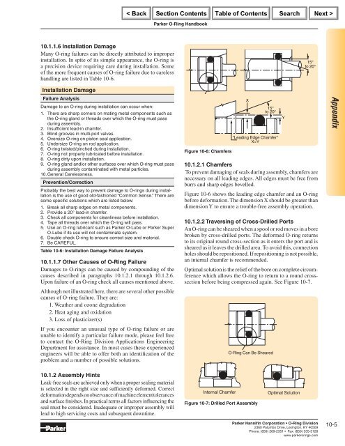
Figure 10-6: Chamfers<br />
X<br />
15°<br />
to 20°<br />
"Leading Edge Chamfer"<br />
X>Y<br />
15°<br />
to 20°<br />
10.1.2.1 Chamfers<br />
To prevent damaging of seals during assembly, chamfers are<br />
necessary on all leading edges. All edges must be free from<br />
burrs and sharp edges bevelled.<br />
Figure 10-6 shows the leading edge chamfer and an O-ring<br />
before deformation. The dimension X should be greater than<br />
dimension Y to ensure a trouble-free assembly operation.<br />
10.1.2.2 Traversing of Cross-Drilled Ports<br />
An O-ring can be sheared when a spool or rod moves in a bore<br />
broken by cross-drilled ports. The deformed O-ring returns<br />
to its original round cross-section as it enters the port and is<br />
sheared as it leaves the drilled area. To avoid this, connection<br />
holes should be repositioned. If repositioning is not possible,<br />
an internal chamfer is recommended.<br />
Optimal solution is the relief of the bore on complete circumference<br />
which allows the O-ring to return to a round crosssection<br />
before being compressed again. See Figure 10-7.<br />
O-<strong>Ring</strong> Can Be Sheared<br />
Internal Chamfer Optimal Solution<br />
Figure 10-7: Drilled Port Assembly<br />
<strong>Parker</strong> Hannifi n Corporation • O-<strong>Ring</strong> Division<br />
2360 Palumbo Drive, Lexington, KY 40509<br />
Phone: (859) 269-2351 Fax: (859) 335-5128<br />
www.parkerorings.com<br />
Y<br />
Appendix<br />
10-5


