

Parker O-Ring Handbook.pdf
Parker O-Ring Handbook.pdf
Parker O-Ring Handbook.pdf

Create successful ePaper yourself
Turn your PDF publications into a flip-book with our unique Google optimized e-Paper software.
for this service. See Section II, Basic O-<strong>Ring</strong> Elastomers, for<br />
more information on rotary seal compounds.<br />
Figure 5-21 shows two methods of “spring loading” the<br />
hard rotary seal. Either of these should only be used when<br />
absolutely necessary to obtain the desired seal.<br />
See Table 5-6 for a rotary seal design example.<br />
5.28 Oscillating Seal<br />
In this guide, two types of oscillating seals are considered:<br />
1. Faucet or valve stems are excellent examples of assemblies<br />
that can be simplifi ed by the use of an O-ring seal. Compression<br />
type or multiple-lip packing can be eliminated, reducing<br />
space requirements and eliminating the need for adjusting or<br />
take-up devices. For applications of this type, if the speed is<br />
under 200 feet per minute, use Design Table 5-2 for selecting<br />
O-ring sizes and gland dimensions.<br />
2. Constantly oscillating shafts, such as those used on timing and<br />
metering devices, can be sealed satisfactorily with O-rings. If<br />
the motion is continuous for long periods of time, use Design<br />
Table 5-4 for O-ring sizes and gland dimensions.<br />
5.29 Seat Seals<br />
A properly designed check or poppet type valve, with an<br />
O-ring on the seat, will give an exceptionally long, non-leaking<br />
service. Many designers and engineers make the costly<br />
mistake of trying to use a conventional groove (square or<br />
rectangular) design to hold the O-ring.<br />
With this type of groove, “blow-out’’ will normally occur<br />
when the valve is unseated.<br />
“Blow-out” is a type of seal failure caused by the action of<br />
the pressure in the system on the side of the O-ring, forcing it<br />
out of the groove into some other part of the valve or system.<br />
“Blow-out” usually occurs at differential pressures above 5.5<br />
Bar (80 psi). The exact pressure will depend on the gas or<br />
fl uid, valve design and the physical properties of the O-ring<br />
when a non-retaining or conventional type groove is used.<br />
It should be kept in mind that blow-out is similar to extrusion,<br />
but that it occurs at considerably lower pressures.<br />
Figure 5-22 shows an O-ring on the seat of a check valve in a<br />
conventional groove. The seal is satisfactory as long as the valve is<br />
not opened at or near the pressure necessary to cause blow-out.<br />
O-<strong>Ring</strong><br />
Pressure<br />
Figure 5-22: Valve Seat Seal, Standard Groove<br />
<strong>Parker</strong> O-<strong>Ring</strong> <strong>Handbook</strong><br />
Figure 5-23 illustrates a valve opening above “blow-out”<br />
pressure. As the valve opens, the space between the two faces<br />
becomes increasingly larger. The pressure opening the valve<br />
is also acting on the O-ring, causing it to continue to seal the<br />
opening until it is stretched completely out of the groove and<br />
is blown out or forced into another part of the system.<br />
Gases such as air, LPG, CO2, etc. enter or permeate the<br />
O-ring. With release of pressure, the gas inside the O-ring<br />
can cause the seal to “balloon” or swell momentarily. (The<br />
amount depends on the pressure.) The ballooning effect that<br />
can occur at very low pressure usually pops the O-ring out of<br />
the groove the same as blow-out. “Ballooning” and “blow-out”<br />
often combine to cause valve seal failure. Another term often<br />
used to describe this phenomenon is “explosive decompression.”<br />
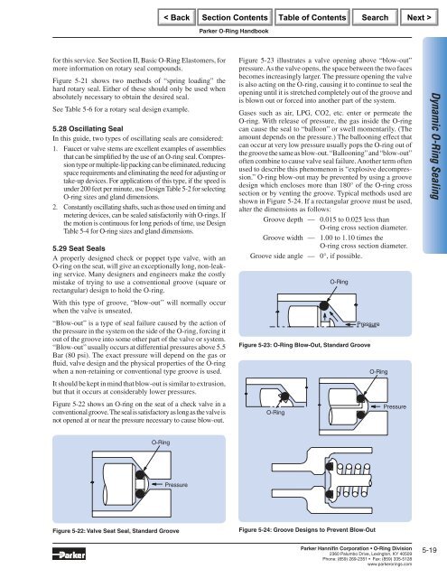
O-ring blow-out may be prevented by using a groove<br />
design which encloses more than 180° of the O-ring cross<br />
section or by venting the groove. Typical methods used are<br />
shown in Figure 5-24. If a rectangular groove must be used,<br />
alter the dimensions as follows:<br />
Groove depth — 0.015 to 0.025 less than<br />
O-ring cross section diameter.<br />
Groove width — 1.00 to 1.10 times the<br />
O-ring cross section diameter.<br />
Groove side angle — 0°, if possible.<br />
O-<strong>Ring</strong><br />
Pressure<br />
Figure 5-23: O-<strong>Ring</strong> Blow-Out, Standard Groove<br />
O-<strong>Ring</strong><br />
Figure 5-24: Groove Designs to Prevent Blow-Out<br />
O-<strong>Ring</strong><br />
Pressure<br />
<strong>Parker</strong> Hannifi n Corporation • O-<strong>Ring</strong> Division<br />
2360 Palumbo Drive, Lexington, KY 40509<br />
Phone: (859) 269-2351 Fax: (859) 335-5128<br />
www.parkerorings.com<br />
Dynamic O-<strong>Ring</strong> Sealing<br />
5-19


