

Parker O-Ring Handbook.pdf
Parker O-Ring Handbook.pdf
Parker O-Ring Handbook.pdf

Create successful ePaper yourself
Turn your PDF publications into a flip-book with our unique Google optimized e-Paper software.
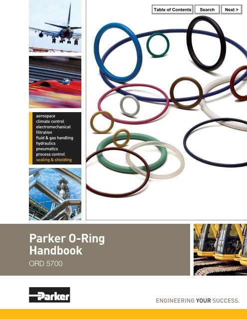
aerospace<br />
climate control<br />
electromechanical<br />
filtration<br />
fluid & gas handling<br />
hydraulics<br />
pneumatics<br />
process control<br />
sealing & shielding<br />
<strong>Parker</strong> O-<strong>Ring</strong><br />
<strong>Handbook</strong><br />
ORD 5700
Failure, improper selection or improper use of the products and/or systems<br />
described herein or related items can cause death, personal injury or property<br />
damage.<br />
This document and other information from <strong>Parker</strong> Hannifi n Corporation, its<br />
subsidiaries and authorized distributors provides product and/or system options<br />
for further investigation by users having technical expertise. It is important<br />
that you analyze all aspects of your application and review the information<br />
concerning the product or system in the current product catalog. Due to the<br />
OFFER OF SALE<br />
The items described in this document are hereby offered for sale by <strong>Parker</strong><br />
Hannifi n Corporation, its subsidiaries and its authorized distributors. This<br />
offer and its acceptance are governed by the provisions stated on the separate<br />
page of this document entitled “Offer of Sale.”<br />
variety of operating conditions and applications for these products or systems,<br />
the user, through his or her own analysis and testing, is solely responsible for<br />
making the fi nal selection of the products and systems and assuring that all<br />
performance, safety and warning requirements of the application are met.<br />
The products described herein, including without limitation, product features,<br />
specifi cations, designs, availability and pricing, are subject to change by <strong>Parker</strong><br />
Hannifi n Corporation and its subsidiaries at any time without notice.<br />
Copyright © 2007, <strong>Parker</strong> Hannifi n Corporation, Cleveland, OH.<br />
All rights reserved.
50 th 50 th 50 th<br />
Anniversary<br />
Edition<br />
Since its initial release in 1957, the <strong>Parker</strong> O-<strong>Ring</strong><br />
<strong>Handbook</strong> has become a fi xture on the reference<br />
shelves of engineers worldwide. This book contains<br />
extensive information about the properties of basic<br />
sealing elastomers, as well as examples of typical<br />
o-ring applications, fundamentals of static and<br />
dynamic seal design and o-ring failure modes. It<br />
also provides an overview of international sizes<br />
and standards, and compatibility data for fl uids,<br />
gases and solids.<br />
Engineers in every industry choose o-rings made by<br />
<strong>Parker</strong> Hannifi n to keep their equipment running<br />
safely and reliably. That’s because <strong>Parker</strong>’s O-<strong>Ring</strong><br />
Division, a developer, manufacturer and supplier of<br />
precision-engineered o-rings, offers a unique combination<br />
of experience, innovation and support.<br />
<strong>Parker</strong> O-<strong>Ring</strong> <strong>Handbook</strong><br />
Value Added Services through <strong>Parker</strong><br />
O-<strong>Ring</strong> Division:<br />
• Desktop seal design – InPhorm software<br />
• Free engineering assistance<br />
• Quality assurance –<br />
TS 16949 / ISO 9001 / AS 9100 registered<br />
• Premier customer service<br />
• Online tools<br />
- temperature/dimension converters<br />
- gland design recommendation charts<br />
- troubleshooting utility<br />
- pressure calculator<br />
• ParZap inventory management<br />
• Worldwide distribution<br />
• Extensive product literature, test reports<br />
and much more...<br />
<strong>Parker</strong> Hannifi n Corporation • O-<strong>Ring</strong> Division<br />
2360 Palumbo Drive, Lexington, KY 40509<br />
Phone: (859) 269-2351 Fax: (859) 335-5128<br />
www.parkerorings.com<br />
I
II<br />
Table of Contents<br />
<strong>Parker</strong> O-<strong>Ring</strong> <strong>Handbook</strong><br />
Introduction – Section I . . . . . . . . . . . . . . . . . . . . . . . . . . . . . . . . . . . . 1-1<br />
Basic O-<strong>Ring</strong> Elastomers – Section II . . . . . . . . . . . . . . . . . . . . . . . . . 2-1<br />
O-<strong>Ring</strong> Applications – Section III . . . . . . . . . . . . . . . . . . . . . . . . . . . . 3-1<br />
Static O-<strong>Ring</strong> Sealing – Section IV . . . . . . . . . . . . . . . . . . . . . . . . . . . 4-1<br />
Dynamic O-<strong>Ring</strong> Sealing – Section V . . . . . . . . . . . . . . . . . . . . . . . . . 5-1<br />
Back-up <strong>Ring</strong>s – Section VI. . . . . . . . . . . . . . . . . . . . . . . . . . . . . . . . . 6-1<br />
Compatibility Tables for Gases, Fluids, Solids – Section VII . . . . . . . 7-1<br />
Specifi cations – Section VIII . . . . . . . . . . . . . . . . . . . . . . . . . . . . . . . . 8-1<br />
Sizes – Section IX . . . . . . . . . . . . . . . . . . . . . . . . . . . . . . . . . . . . . . . . 9-1<br />
Appendix – Section X . . . . . . . . . . . . . . . . . . . . . . . . . . . . . . . . . . . . 10-1<br />
Index – Section XI . . . . . . . . . . . . . . . . . . . . . . . . . . . . . . . . . . . . . . . 11-1<br />
<strong>Parker</strong> Hannifi n Corporation • O-<strong>Ring</strong> Division<br />
2360 Palumbo Drive, Lexington, KY 40509<br />
Phone: (859) 269-2351 Fax: (859) 335-5128<br />
www.parkerorings.com
Section I – Introduction<br />
1.0 How to Use This <strong>Handbook</strong>. . . . . . . . . . . . . . . . . . . 1-2<br />
1.1 What is an O-<strong>Ring</strong>? . . . . . . . . . . . . . . . . . . . . . . . . . 1-2<br />
1.2 What is an O-<strong>Ring</strong> Seal? . . . . . . . . . . . . . . . . . . . . . 1-2<br />
1.3 Advantages of O-<strong>Ring</strong>s . . . . . . . . . . . . . . . . . . . . . . 1-2<br />
1.4 Operation . . . . . . . . . . . . . . . . . . . . . . . . . . . . . . . . . 1-3<br />
1.5 O-<strong>Ring</strong> Characteristics. . . . . . . . . . . . . . . . . . . . . . . 1-3<br />
1.6 Limitations of O-<strong>Ring</strong> Use. . . . . . . . . . . . . . . . . . . . 1-4<br />
1.7 Scope of O-<strong>Ring</strong> Use . . . . . . . . . . . . . . . . . . . . . . . . 1-4<br />
1.7.1 Static Seals . . . . . . . . . . . . . . . . . . . . . . . . . . . . 1-5<br />
1.7.2 Reciprocating Seals . . . . . . . . . . . . . . . . . . . . . 1-5<br />
1.7.3 Oscillating Seals. . . . . . . . . . . . . . . . . . . . . . . . 1-5<br />
1.7.4 Rotary Seals . . . . . . . . . . . . . . . . . . . . . . . . . . . 1-5<br />
1.7.5 Seat Seals . . . . . . . . . . . . . . . . . . . . . . . . . . . . . 1-5<br />
1.7.6 Pneumatic Seals . . . . . . . . . . . . . . . . . . . . . . . . 1-5<br />
1.7.7 Vacuum Seals . . . . . . . . . . . . . . . . . . . . . . . . . . 1-6<br />
1.7.8 Cushion Installation . . . . . . . . . . . . . . . . . . . . . 1-6<br />
1.7.9 Crush Installation . . . . . . . . . . . . . . . . . . . . . . . 1-6<br />
1.7.10 Rod Wiper Installation . . . . . . . . . . . . . . . . . . 1-6<br />
inPHorm is a trademark of <strong>Parker</strong> Hannifi n Corporation.<br />
<strong>Parker</strong> O-<strong>Ring</strong> <strong>Handbook</strong><br />
1.8 O-<strong>Ring</strong>s as Drive Belts . . . . . . . . . . . . . . . . . . . . . . 1-6<br />
1.9 Custom Molded Shapes . . . . . . . . . . . . . . . . . . . . . . 1-6<br />
1.10 <strong>Parker</strong> Engineering. . . . . . . . . . . . . . . . . . . . . . . . . 1-6<br />
1.11 Comparison of Common Seal Types . . . . . . . . . . . 1-7<br />
1.12 Recommended Design Procedure . . . . . . . . . . . . . 1-7<br />
1.12.1 O-<strong>Ring</strong> Design Procedure Using<br />
inPHorm O-<strong>Ring</strong> Design &<br />
Material Selection Software . . . . . . . . . . . . . . . . . 1-7<br />
1.12.2 Recommended Manual Design Procedure. . . 1-7<br />
<strong>Parker</strong> Hannifi n Corporation • O-<strong>Ring</strong> Division<br />
2360 Palumbo Drive, Lexington, KY 40509<br />
Phone: (859) 269-2351 Fax: (859) 335-5128<br />
www.parkerorings.com<br />
Introduction<br />
1-1
Introduction<br />
1-2<br />
Introduction<br />
1.0 How to Use This <strong>Handbook</strong><br />
For those who are unfamiliar with O-ring design, it is recommended<br />
to fi rst study this introductory section, becoming<br />
familiar with the basic principles of O-ring seals, their common<br />
uses and general limitations. Introduction<br />
Those who are already familiar with O-ring seal design may<br />
simply refer to the appropriate design tables for the information<br />
needed. Even those who have designed many O-ring seals<br />
may profi t by reviewing the basics from time to time.<br />
1.1 What is an O-<strong>Ring</strong>?<br />
An O-ring is a torus, or doughnut-shaped ring, generally<br />
molded from an elastomer, although O-rings are also made<br />
from PTFE and other thermoplastic materials, as well as metals,<br />
both hollow and solid. This handbook, however, deals<br />
entirely with elastomeric O-rings.<br />
O-rings are used primarily for sealing. The various types of<br />
O-ring seals are described in this section under “Scope of<br />
O-<strong>Ring</strong> Use.” O-rings are also used as light-duty, mechanical<br />
drive belts. More information, including design criteria<br />
on O-ring drive belts and their application will be found in<br />
O-<strong>Ring</strong> Applications, Section III.<br />
1.2 What is an O-<strong>Ring</strong> Seal?<br />
An O-ring seal is used to prevent the loss of a fl uid or gas. The<br />
seal assembly consists of an elastomer O-ring and a gland.<br />
An O-ring is a circular cross-section ring molded from rubber<br />
(Figure 1-1). The gland — usually cut into metal or another<br />
rigid material — contains and supports the O-ring (Figures<br />
1-2 and 1-3). The combination of these two elements; O-ring<br />
and gland — constitute the classic O-ring seal assembly.<br />
Figure 1-1: Basic O-Rng<br />
<strong>Parker</strong> O-<strong>Ring</strong> <strong>Handbook</strong><br />
1.3 Advantages of O-<strong>Ring</strong>s<br />
• They seal over a wide range of pressure, temperature and<br />
tolerance.<br />
• Ease of service, no smearing or retightening.<br />
• No critical torque on tightening, therefore unlikely to<br />
cause structural damage.<br />
• O-rings normally require very little room and are light<br />
in weight.<br />
• In many cases an O-ring can be reused, an advantage<br />
over non-elastic fl at seals and crush-type gaskets.<br />
• The duration of life in the correct application corresponds<br />
to the normal aging period of the O-ring material.<br />
• O-ring failure is normally gradual and easily identifi ed.<br />
• Where differing amounts of compression effect the seal<br />
function (as with fl at gaskets), an O-ring is not effected<br />
because metal to metal contact is generally allowed for.<br />
• They are cost-effective.<br />
Groove<br />
Figure 1-2: Basic Gland<br />
Figure 1-3: Gland and O-<strong>Ring</strong> Seal<br />
Bore<br />
Piston Rod<br />
<strong>Parker</strong> Hannifi n Corporation • O-<strong>Ring</strong> Division<br />
2360 Palumbo Drive, Lexington, KY 40509<br />
Phone: (859) 269-2351 Fax: (859) 335-5128<br />
www.parkerorings.com
1.4 Operation<br />
All robust seals are characterized by the absence of any<br />
pathway by which fl uid or gas might escape. Detail differences<br />
exist in the manner by which zero clearance is obtained<br />
— welding, brazing, soldering, ground fi ts or lapped fi nishes<br />
— or the yielding of a softer material wholly or partially<br />
confi ned between two harder and stiffer members of the<br />
assembly. The O-ring seal falls in the latter class.<br />
The rubber seal should be considered as essentially an<br />
incompressible, viscous fl uid having a very high surface<br />
tension. Whether by mechanical pressure from the surrounding<br />
structure or by pressure transmitted through hydraulic fl uid,<br />
this extremely viscous fl uid is forced to fl ow within the gland<br />
to produce “zero clearance” or block to the fl ow of the less<br />
viscous fl uid being sealed. The rubber absorbs the stack-up<br />
of tolerances of the unit and its internal memory maintains<br />
the sealed condition. Figure 1-4 illustrates the O-ring as<br />
installed, before the application of pressure. Note that the<br />
O-ring is mechanically squeezed out of round between the<br />
outer and inner members to close the fl uid passage. The seal<br />
material under mechanical pressure extrudes into the microfi ne<br />
grooves of the gland. Figure 1-5 illustrates the application of<br />
fl uid pressure on the O-ring. Note that the O-ring has been<br />
forced to fl ow up to, but not into, the narrow gap between<br />
the mating surfaces and in so doing, has gained greater area<br />
and force of sealing contact. Figure 1-6 shows the O-ring at<br />
its pressure limit with a small portion of the seal material<br />
entering the narrow gap between inner and outer members of<br />
the gland. Figure 1-7 illustrates the result of further increasing<br />
pressure and the resulting extrusion failure. The surface<br />
tension of the elastomer is no longer suffi cient to resist fl ow<br />
and the material extrudes (fl ows) into the open passage or<br />
clearance gap.<br />
Figure 1-4: O-<strong>Ring</strong> Installed<br />
Figure 1-5: O-<strong>Ring</strong> Under<br />
Pressure<br />
Figure 1-6: O-<strong>Ring</strong> Extruding Figure 1-7: O-<strong>Ring</strong> Failure<br />
(1) “O-<strong>Ring</strong> Seals in the Design of Hydraulic Mechanisms”, a paper presented<br />
at the S.A.E. Annual Meeting, January, 1947 by Mr. D. R. Pearl of Hamilton<br />
Standard Prop. Div. of United Aircraft Corp.<br />
<strong>Parker</strong> O-<strong>Ring</strong> <strong>Handbook</strong><br />
1.5 O-<strong>Ring</strong> Characteristics<br />
A very early and historically prominent user of O-rings (1)<br />
cites a number of characteristics of O-ring seals which are<br />
still of interest to seal designers. Extracts of the more general<br />
characteristics are listed as follows:<br />
Note: While <strong>Parker</strong> Seal generally agrees with the author<br />
on most of his statements, exception will be taken to certain<br />
generalizations due to more recent developments in sealing<br />
geometry and improved elastomer technology.<br />
A. The seals can be made perfectly leak-proof for cases of<br />
static pistons and cylinders for fl uid pressures up to 5000<br />
psi. (Limit of test pressure). The pressure may be constant<br />
or variable.<br />
B. The seals can be made to seal satisfactorily between<br />
reciprocating pistons and cylinders at any fl uid pressure<br />
up to 5000 psi. There may be slight running leakage (a<br />
few drops per hundred strokes) depending on the fi lmforming<br />
ability of the hydraulic medium. O-rings can be<br />
used between rotating members with similar results but<br />
in all cases the surface rubbing speed must be kept low.<br />
C. A single O-ring will seal with pressure applied alternately<br />
on one side and then on the other, but in cases of severe<br />
loading or usage under necessarily unfavorable conditions,<br />
seal life can be extended by designing the mechanism so<br />
that each seal is subjected to pressure in one direction only.<br />
Seals may be arranged in series as a safety measure but<br />
the fi rst seal exposed to pressure will take the full load.<br />
D. O-ring seals must be radially compressed between the<br />
bottom of the seal groove and the cylinder wall for proper<br />
sealing action. This compression may cause the seal to roll<br />
slightly in its groove under certain conditions of piston<br />
motion, but the rolling action is not necessary for normal<br />
operation of the seals.<br />
E. In either static or dynamic O-ring seals under high pressure<br />
the primary cause of seal failure is extrusion of the<br />
seal material into the piston-cylinder clearance. The<br />
major factors effecting extrusion are fl uid pressure, seal<br />
hardness and strength, and piston-cylinder clearance.<br />
F. Dynamic seals may fail by abrasion against the cylinder<br />
or piston walls. Therefore, the contacting surfaces should<br />
be polished for long seal life. Moving seals that pass over<br />
ports or surface irregularities while under hydraulic pressure<br />
are very quickly cut or worn to failure.<br />
G. The shape of the seal groove is unimportant as long as<br />
it results in proper compression of the seal between the<br />
bottom of the groove and the cylinder wall, and provides<br />
room for the compressed material to fl ow so that the seal<br />
is not solidly confi ned between metal surfaces.<br />
H. The seal may be housed in a groove cut in the cylinder<br />
wall instead of on the piston surface without any change<br />
in design limitations or seal performance.<br />
<strong>Parker</strong> Hannifi n Corporation • O-<strong>Ring</strong> Division<br />
2360 Palumbo Drive, Lexington, KY 40509<br />
Phone: (859) 269-2351 Fax: (859) 335-5128<br />
www.parkerorings.com<br />
Introduction<br />
1-3
Introduction<br />
1-4<br />
I. Friction of moving O-ring seals depends primarily on<br />
seal compression, fl uid pressure, and projected seal area<br />
exposed to pressure. The effects of materials, surfaces,<br />
fl uids, and speeds of motion are normally of secondary<br />
importance, although these variables have not been completely<br />
investigated. Friction of O-ring seals under low<br />
pressures may exceed the friction of properly designed<br />
lip type seals, but at higher pressures, developed friction<br />
compares favorably with, and is often less than, the friction<br />
of equivalent lip type seals.<br />
J. The effects of temperature changes from +18°C to +121°C<br />
(-65°F to +250°F) on the performance of O-ring seals<br />
depends upon the seal material used. Synthetic rubber<br />
can be made for continual use at high or low temperatures,<br />
or for occasional short exposure to wide variations<br />
in temperature. At extremely low temperature the seals<br />
may become brittle but will resume their normal fl exibility<br />
without harm when warmed. Prolonged exposure<br />
to excessive heat causes permanent hardening and usually<br />
destroys the usefulness of the seal. The coeffi cient<br />
of thermal expansion of synthetic rubber is usually low<br />
enough so that temperature changes present no design<br />
diffi culties. (Note: This may not be true for all elastomer<br />
compounds, especially FFKM.)<br />
K. Chemical interaction between the seal and the hydraulic<br />
medium may infl uence seal life favorably or unfavorably,<br />
depending upon the combination of seal material and fl uid.<br />
Excessive hardening, softening, swelling, and shrinkage<br />
must be avoided.<br />
L. O-ring seals are extremely dependable because of their<br />
simplicity and ruggedness. Static seals will seal at high<br />
pressure in spite of slightly irregular sealing surfaces<br />
and slight cuts or chips in the seals. Even when broken<br />
or worn excessively, seals may offer some measure of<br />
fl ow restriction for emergency operation and approaching<br />
failure becomes evident through gradual leakage.<br />
M. The cost of O-ring seals and the machining expense necessary<br />
to incorporate them into hydraulic mechanism designs<br />
are at least as low as for any other reliable type of seal.<br />
O-ring seals may be stretched over large diameters for<br />
installation and no special assembly tools are necessary.<br />
N. Irregular chambers can be sealed, both as fi xed or moving-parts<br />
installations.<br />
Note: See paragraph 1.3 for additional advantages.<br />
1.6 Limitations of O-<strong>Ring</strong> Use<br />
Again citing Mr. D. R. Pearl’s paper (1) , limitations of O-ring<br />
use are given as:<br />
“Although it has been stated that O-rings offer a reasonable<br />
approach to the ideal hydraulic seal, they should<br />
not be considered the immediate solution to all sealing<br />
problems. It has been brought out in the foregoing<br />
discussion that there are certain defi nite limitations on<br />
(1) “O-<strong>Ring</strong> Seals in the Design of Hydraulic Mechanisms”, a paper presented<br />
at the S.A.E. Annual Meeting, January, 1947 by Mr. D. R. Pearl, Hamilton<br />
Standard Division of United Aircraft Corp.<br />
<strong>Parker</strong> O-<strong>Ring</strong> <strong>Handbook</strong><br />
their use, i.e., high temperature, high rubbing speeds,<br />
cylinder ports over which seals must pass and large<br />
shaft clearances. Disregard for these limitations will<br />
result in poor seal performance. Piston rings, lip type<br />
seals, lapped fi ts, fl at gaskets and pipe fi ttings all have<br />
their special places in hydraulic design, but where<br />
the design specifi cations permit the proper use of<br />
O-ring seals, they will be found to give long and dependable<br />
service.”<br />
While no claim is made that an O-ring will serve best in all<br />
conditions, the O-ring merits consideration for most seal<br />
applications except:<br />
A. Rotary speeds exceeding 1500 feet per minute contact<br />
speed.<br />
B. An environment completely incompatible with any elastomeric<br />
material.<br />
C. Insuffi cient structure to support anything but a fl at gasket.<br />
Note: These points are general statements and there are,<br />
of course, numerous exceptions. Details of O-ring seal<br />
design in regard to particular situations are discussed in<br />
the following sections: Applications, Elastomers, Factors<br />
Applying To all O-<strong>Ring</strong> Types, Static O-<strong>Ring</strong> Seals, and<br />
Dynamic O-<strong>Ring</strong> Seals can be referenced as needed.<br />
1.7 Scope of O-<strong>Ring</strong> Use<br />
Further discussion in this chapter and in the remainder of<br />
this handbook is based on specifi c types of O-ring seals and<br />
special applications. Defi nitions of commonly used terms<br />
connected with O-ring seals are provided in the glossary<br />
contained in the Appendix, Section X. These terms are common<br />
to the sealing industry.<br />
Figure 1-8: Static Seal Application<br />
<strong>Parker</strong> Hannifi n Corporation • O-<strong>Ring</strong> Division<br />
2360 Palumbo Drive, Lexington, KY 40509<br />
Phone: (859) 269-2351 Fax: (859) 335-5128<br />
www.parkerorings.com
1.7.1 Static Seals<br />
In a truly static seal, the mating gland parts are not subject<br />
to relative movement (except for small thermal expansion<br />
or separation by fl uid pressure), as contrasted from seals in<br />
which one of the gland parts has movement relative to the<br />
other. Examples of static seals are: a seal under a bolt head<br />
or rivet, a seal at a pipe or tubing connection, a seal under a<br />
cover plate, plug or similar arrangement or, in general, the<br />
equivalent of a fl at gasket. Figure1-8 illustrates a typical<br />
static seal.<br />
Note: True static seals are generally quite rare. Vibrational<br />
movement is present in vitrually all static applications.<br />
1.7.2 Reciprocating Seals<br />
In a reciprocating seal, there is relative reciprocating motion<br />
(along the shaft axis) between the inner and outer elements.<br />
This motion tends to slide or roll the O-ring, or sealing<br />
surface at the O-ring, back and forth with the reciprocal<br />
motion. Examples of a reciprocating seal would be a piston<br />
in a cylinder, a plunger entering a chamber, and a hydraulic<br />
actuator with the piston rod anchored. Figure 1-9 illustrates<br />
a typical reciprocating seal.<br />
Note: O-ring seals are generally not recommended for reciprocating<br />
installations in which the speed is less than one foot<br />
per minute. Consult a <strong>Parker</strong> Territory Sales Manager for more<br />
information on special seals to meet this requirement.<br />
1.7.3 Oscillating Seals<br />
In an oscillating seal, the inner or outer member of the seal<br />
assembly moves in an arc (around the shaft axis) relative to<br />
the other member. This motion tends to rotate one or the other<br />
member in relation to the O-ring. Where the arc of motion<br />
exceeds 360°, as in multiple turns to operate a valve handle,<br />
the return arc in the opposite direction distinguishes the oscillating<br />
seal from a rotary seal. Except for very special cases,<br />
any longitudinal motion (as caused by a spiral thread) involved<br />
in what is classed as an oscillating seal is not important. An<br />
example of an oscillating seal is an O-ring seal for a faucet<br />
valve stem. See Figure 1-10.<br />
Figure 1-9: Reciprocating Seal Application<br />
<strong>Parker</strong> O-<strong>Ring</strong> <strong>Handbook</strong><br />
1.7.4 Rotary Seals<br />
In a rotary seal, either the inner or outer member of the sealing<br />
elements turn (around the shaft axis) in one direction only.<br />
This applies when rotation is reversible, but does not allow<br />
for starting and stopping after brief arcs of motion, which<br />
is classed as an oscillating seal. Examples of a rotary seal<br />
include sealing a motor or engine shaft, or a wheel on a fi xed<br />
axle. See Figure 1-11.<br />
1.7.5 Seat Seals<br />
In a seat seal, the O-ring serves to close a fl ow passage as<br />
one of the contact members. The motion of closing the passage<br />
distorts the O-ring mechanically to create the seal, in<br />
contrast to conditions of sealing in previously defi ned types.<br />
A sub-classifi cation is closure with impact as compared<br />
with non-impact closure. Examples of a seat-seal include<br />
O-ring as a “washer” on the face of a spiral threaded valve, a<br />
seal on the cone of a fl oating check valve, and a seal on the<br />
end of a solenoid plunger. See Figure 1-12.<br />
1.7.6 Pneumatic Seals<br />
A pneumatic seal may be any of the previously described<br />
types of O-ring seals but is given a different classifi cation<br />
because of the use of a gas or vapor rather than a liquid.<br />
This has a vital affect on the lubrication of the O-ring and<br />
thus infl uences all moving (or dynamic) seal installations.<br />
A further point is that pneumatic seals may be affected by<br />
the increase in gas temperature with compression. Note that<br />
the seal should be defi ned as “pneumatic-rotary” etc. for<br />
complete identifi cation.<br />
Figure 1-10: Oscillating Seal<br />
Figure 1-11: Rotary Seal<br />
Figure 1-12: Seat Seal<br />
Note that groove size<br />
prevents rotation of O-ring<br />
<strong>Parker</strong> Hannifi n Corporation • O-<strong>Ring</strong> Division<br />
2360 Palumbo Drive, Lexington, KY 40509<br />
Phone: (859) 269-2351 Fax: (859) 335-5128<br />
www.parkerorings.com<br />
Introduction<br />
1-5
Introduction<br />
1-6<br />
1.7.7 Vacuum Sealing<br />
A vacuum seal confi nes or contains a vacuum environment<br />
or chamber. The vacuum seal may be any of the previously<br />
defi ned types (except a pneumatic seal) and as in the case of<br />
“pneumatic seals”, both terms applicable to the seal should<br />
be given for complete identifi cation. This classifi cation is<br />
given primarily because, in most cases, the leakage tolerance<br />
is less than for pressure seals. In addition, the problem of<br />
pressure trapped between multiple O-rings, which increases<br />
the load on a single O-ring, does not apply. Multiple O-rings<br />
are useful in a vacuum seal to reduce permeation. Additional<br />
information on the use of O-rings for sealing in a vacuum<br />
environment may be found in <strong>Parker</strong> Catalog 5705A, Vacuum<br />
Sealing. See also Section III, O-<strong>Ring</strong> Applications.<br />
1.7.8 Cushion Installation<br />
Such an application requires that the O-ring absorb the force<br />
of impact or shock by deformation of the ring. Thus, forcible,<br />
sudden contact between moving metal parts is prevented. It<br />
is essentially a mechanical device. An example is the use of<br />
an O-ring to prevent metal-to-metal bottoming of a piston<br />
in a cylinder. The O-ring must be properly held in place as<br />
otherwise it might shift and interfere with proper operation<br />
of the mechanism.<br />
1.7.9 Crush Installation<br />
This use of an O-ring is a variation of the static seal. The<br />
O-ring is crushed into a space having a cross-section different<br />
from that of a standard gland — for example, triangular.<br />
While it is an effective seal, the O-ring is permanently deformed<br />
and therefore generally considered non-reusable. See<br />
Figure 1-13 and Design Chart 4-6 in Section IV for further<br />
information.<br />
1.7.10 Rod Wiper Installation<br />
In this case, the O-ring is used to keep a reciprocating shaft<br />
or rod clean to prevent damaging an O-ring seal located inboard<br />
from the wiper. The wiper O-ring does not necessarily<br />
seal. If there is a possibility of trapping liquid between the<br />
wiper and sealing O-rings, the space between the two must<br />
be vented. This installation is effective on actuating cylinders<br />
of machinery used in dirty, dusty areas. See Figure1-14.<br />
1.8 O-<strong>Ring</strong>s as Drive Belts<br />
O-rings make superior low-power drive belts. See O-ring<br />
Applications, Section III for additional information on drive<br />
belt design.<br />
Figure 1-13: Crush Installation<br />
O-ring volume is usually<br />
90-95% gland volume<br />
<strong>Parker</strong> O-<strong>Ring</strong> <strong>Handbook</strong><br />
1.9 Custom Molded Shapes<br />
Molded shapes consist of homogenous rubber parts functioning<br />
as sealing devices in both dynamic and static applications.<br />
Relying on <strong>Parker</strong> custom designed seals can mean total sealing,<br />
cost reduction, fast service, and quality assurance to you.<br />
Contact the <strong>Parker</strong> Engineered Seals Division for more specifi c<br />
information on the availability of custom molded shapes.<br />
1.10 <strong>Parker</strong> Engineering<br />
<strong>Parker</strong>’s Application Engineering Department personnel are prepared<br />
to help you solve your sealing problems in several ways:<br />
Design Assistance<br />
Our engineers will review your application, study all factors<br />
involved such as temperatures, pressures, gland design, bolt<br />
torque, surface fi nish, etc., and suggest several alternate<br />
designs. They will work with you in researching and testing<br />
those selected until the best possible seal is achieved, based<br />
on performance and low manufacturing cost.<br />
Compound Development<br />
Although the geometric confi guration of the seal is critical, it<br />
is also very important to select the most appropriate compound<br />
for the specifi c application. Even though <strong>Parker</strong> has many<br />
compounds available, we are always ready to develop a special<br />
compound having its own distinct properties tailored to the<br />
needs of a particular application. To insure that these physical<br />
properties are achieved with each batch of material, <strong>Parker</strong><br />
has designed a control system called “C.B.I.” The initials<br />
“C.B.I.” stand for “Controlled Batch Identifi cation”. This is<br />
a system of batch numbering and traceability developed by<br />
<strong>Parker</strong> Seal Group which ties the quality assurance system<br />
together from the masterbatch to the fi nished seals.<br />
Total Quality Management<br />
The <strong>Parker</strong> Seal Group employs a TS16949/AS9100 based<br />
system to assure a continuing standard of quality that is commensurate<br />
with good manufacturing practices. However, in<br />
many cases — as in custom designed molded shapes — a<br />
special quality assurance procedure will be developed for each<br />
individual molded shape with emphasis on the importance of<br />
the actual working area (or sealing interface) of the seal.<br />
Pressure<br />
O-ring Seal<br />
Figure 1-14: Wiper Installation<br />
Vent<br />
Wiper O-ring<br />
Cut in two to<br />
prevent pressure<br />
trap<br />
<strong>Parker</strong> Hannifi n Corporation • O-<strong>Ring</strong> Division<br />
2360 Palumbo Drive, Lexington, KY 40509<br />
Phone: (859) 269-2351 Fax: (859) 335-5128<br />
www.parkerorings.com
1.11 Comparison of Common Seal Types<br />
A number of common seal types, T-Seals, U-Cups,<br />
V-Packing and other devices, have been, and are still used for<br />
both dynamic and static seals. When compared with an O-ring<br />
seal, these other seal types may show one or more design disadvantages<br />
which might be overcome by use of an O-ring. As an<br />
aid in assessing the relative merits of an O-ring seal, Table1-1<br />
lists several of the important factors that must be considered<br />
in the selection of any effective seal geometry.<br />
1.12 Recommended Design Procedure<br />
The following design steps are recommended for the designer/<br />
engineer who is not familiar with O-ring seals:<br />
• O-<strong>Ring</strong> Design Procedure using inPHorm O-<strong>Ring</strong> Design<br />
& Material Selection Software described in paragraph<br />
1.12.1<br />
• Recommended Manual Design Procedure described in<br />
paragraph 1.12.2<br />
1.12.1 O-<strong>Ring</strong> Design Procedure using inPHorm<br />
O-<strong>Ring</strong> Design & Material Selection Software.<br />
<strong>Parker</strong> recommends utilizing our inPHorm design software to<br />
guide the user through the design and selection of an O-ring and<br />
corresponding seal gland. <strong>Parker</strong>’s inPHorm not only addresses<br />
standard O-ring sizes, but allows the user to custom design<br />
O-ring glands and seals specifi cally for their application. To<br />
obtain inPHorm software, contact <strong>Parker</strong> Product Information<br />
at 1-800-C-PARKER or download from www.parkerorings.<br />
com. If inPHorm is not readily available manual calculations<br />
can be performed using the following guidelines.<br />
1.12.2 Recommended Manual Design Procedure<br />
1. Study the Basic O-<strong>Ring</strong> Elastomers and O-<strong>Ring</strong> Applications<br />
Sections (II and III, respectively) to see how<br />
a compound is selected, learn the effects of various<br />
environments on them, and become familiar with those<br />
considerations that apply to all O-ring seal glands.<br />
Comparison of Seal Types<br />
<strong>Parker</strong> O-<strong>Ring</strong> <strong>Handbook</strong><br />
2. Check the Appendix, Section X, for the compound<br />
shrinkage class tables. If it is not AN shrinkage, it may<br />
be necessary to compensate in the gland design for best<br />
sealing results.<br />
3. Find the recommended O-ring size and gland dimensions<br />
in the appropriate design table in Static O-<strong>Ring</strong> Sealing or<br />
Dynamic O-<strong>Ring</strong> Sealing, Sections IV and V, respectively.<br />
4. For industrial use, order the O-rings by the <strong>Parker</strong> compound<br />
number followed by the appropriate size number.<br />
Example: N0674-70 2-325<br />
For the experienced O-ring seal designer:<br />
1. Determine the gland design for best sealing results.<br />
(a) If the fl uid medium or its specifi cation is known,<br />
refer to the Fluid Compatibility Tables in Section<br />
VII or to the various material or other specifi cations<br />
listed in Section VIII.<br />
(b) If the compound specifi cation is known, refer to<br />
Table 8-2, Table 8-3 or Table 8-4 in Section VIII as<br />
applicable.<br />
2. Check the Appendix, Section X, for the compound<br />
shrinkage class tables. If it is not AN shrinkage, it may<br />
be necessary to compensate in the gland design for best<br />
sealing results.<br />
3. Find the recommended O-ring size and gland dimensions<br />
in the appropriate design table in Static O-<strong>Ring</strong> Sealing or<br />
Dynamic O-<strong>Ring</strong> Sealing, Sections IV and V, respectively.<br />
4. For industrial use, order the O-rings by the <strong>Parker</strong> compound<br />
number followed by the size number.<br />
Example: N0674-70 2-325<br />
When ordering parts made with a military, AMS, or NAS<br />
specifi cation material, see the Specifi cations Section VIII.<br />
Example: M83248/1-325<br />
5. For a design problem that cannot be resolved using the<br />
information in this reference guide, fi ll out a copy of the<br />
“Statement of Problem” sheet, Table 1-2, as completely<br />
as possible, then Contact the <strong>Parker</strong> O-<strong>Ring</strong> Division for<br />
problem analysis and design recommendations.<br />
Applications<br />
Periodic<br />
Adjustment Moving<br />
Tolerances<br />
Required<br />
Gland<br />
Adapters Space<br />
Type Static Moving Required Friction (Moving Seals) Required Requirements<br />
O-<strong>Ring</strong> X X No Medium Close No Small<br />
T-Seal X X No Medium Fairly Close No Small<br />
U-Packing — X No Low Close No Small<br />
V-Packing — X Yes Medium Fairly Close Yes Large<br />
Cup Type<br />
Packing<br />
— X No Medium Close Yes Medium<br />
Flat Gasket X — Yes — — No Large<br />
Compression or<br />
Jam Packing<br />
X X Yes High Fairly Close Yes Large<br />
Table 1-1: Comparison of Seal Types<br />
<strong>Parker</strong> Hannifi n Corporation • O-<strong>Ring</strong> Division<br />
2360 Palumbo Drive, Lexington, KY 40509<br />
Phone: (859) 269-2351 Fax: (859) 335-5128<br />
www.parkerorings.com<br />
Introduction<br />
1-7
Introduction<br />
1-8<br />
Statement of Problem<br />
1. Seal Type<br />
2. Fluid Sealed<br />
(In sequence if multiple)<br />
<strong>Parker</strong> O-<strong>Ring</strong> <strong>Handbook</strong><br />
A. B.<br />
C. D. Material Spec.<br />
3. Temperature High Low Working<br />
4. Pressure High Low Working<br />
5. Applied Pressure Uni-Directional Steady Surge<br />
6. Gland Dimensions<br />
(If separate, groove wall)<br />
7. Max. Stretch at Installation<br />
Bi-Directional Fluctuating Frequency<br />
OD Finish Material<br />
ID Finish Material<br />
Finish Material<br />
8. Assembly Problems Dirt Lint Lube<br />
Moving Seals<br />
Twisted Blind Pinching<br />
Over Threads Corners, Holes, Etc.<br />
9. Length of Stroke (Reciprocating) Arc of Travel (Oscillating)<br />
Surface Speed (Rotary) Frequency<br />
(Oscillating or Reciprocating)<br />
10. Shaft Bearings No<br />
Side Loading Effect Eccentricity<br />
11. Operating Clearance Max. Min.<br />
12. Leakage Tolerance<br />
13. Friction Tolerance Breakaway Running<br />
14. Anticipated Overhaul Period<br />
Ease of Access and<br />
Replacement<br />
15. Lubrication By Fluid Sealed External<br />
16. Cleanliness Protected Open Bad<br />
O-<strong>Ring</strong> Size No. And <strong>Parker</strong> Compound No. Or Military Part No.<br />
17. Please include a drawing or sketch if needed to clarify the assembly, and add any other pertinent information.<br />
NOTE: For O-rings molded of compounds having other than standard shrinkage, determine the fi nished dimensions and tolerances as described in the<br />
Appendix (Section X).<br />
Table 1-2: Statement of Problem<br />
<strong>Parker</strong> Hannifi n Corporation • O-<strong>Ring</strong> Division<br />
2360 Palumbo Drive, Lexington, KY 40509<br />
Phone: (859) 269-2351 Fax: (859) 335-5128<br />
www.parkerorings.com
Section II – Basic O-<strong>Ring</strong> Elastomers<br />
2.0 Elastomers . . . . . . . . . . . . . . . . . . . . . . . . . . . . . . . . 2-2<br />
2.1 Introduction to Elastomers. . . . . . . . . . . . . . . . . . . . 2-2<br />
2.1.1 Polymer . . . . . . . . . . . . . . . . . . . . . . . . . . . . . . 2-2<br />
2.1.2 Rubber . . . . . . . . . . . . . . . . . . . . . . . . . . . . . . . 2-3<br />
2.1.3 Elastomer . . . . . . . . . . . . . . . . . . . . . . . . . . . . . 2-3<br />
2.1.4 Compound . . . . . . . . . . . . . . . . . . . . . . . . . . . . 2-3<br />
2.2 Basic Elastomers for O-<strong>Ring</strong> Seals . . . . . . . . . . . . . 2-3<br />
2.2.1 Acrylonitrile-Butadiene (NBR) . . . . . . . . . . . . 2-3<br />
2.2.2 Carboxylated Nitrile (XNBR) . . . . . . . . . . . . . 2-4<br />
2.2.3 Ethylene Acrylate (AEM, Vamac ® ) . . . . . . . . . 2-4<br />
2.2.4 Ethylene Propylene Rubber (EPR, EPDM) . . . 2-4<br />
2.2.5 Butyl Rubber (IIR) . . . . . . . . . . . . . . . . . . . . . . 2-4<br />
2.2.6 Chloroprene Rubber (CR) . . . . . . . . . . . . . . . . 2-5<br />
2.2.7 Fluorocarbon (FKM, FPM) . . . . . . . . . . . . . . . 2-5<br />
2.2.8 Fluorosilicone (FVMQ) . . . . . . . . . . . . . . . . . . 2-5<br />
2.2.9 Hydrogenated Nitrile (HNBR). . . . . . . . . . . . . 2-5<br />
2.2.10 Perfl uoroelastomer (FFKM). . . . . . . . . . . . . . 2-6<br />
2.2.11 Polyacrylate (ACM) . . . . . . . . . . . . . . . . . . . . 2-6<br />
2.2.12 Polyurethane (AU, EU) . . . . . . . . . . . . . . . . . 2-6<br />
2.2.13 Silicone Rubber (Q, MQ, VMQ, PVMQ) . . . 2-6<br />
2.2.14 Tetrafl uoroethylene-Propylene<br />
(AFLAS ® ) (FEPM). . . . . . . . . . . . . . . . . . . . . . . . 2-6<br />
2.3 Compound Selection and Numbering Systems . . . . 2-7<br />
2.3.1 Selection of Base Polymer . . . . . . . . . . . . . . . . 2-7<br />
2.4 Physical and Chemical Characteristics . . . . . . . . . . 2-8<br />
2.4.1 Resistance to Fluid . . . . . . . . . . . . . . . . . . . . . . 2-8<br />
2.4.2 Hardness. . . . . . . . . . . . . . . . . . . . . . . . . . . . . . 2-9<br />
2.4.3 Toughness. . . . . . . . . . . . . . . . . . . . . . . . . . . . 2-10<br />
2.4.4 Tensile Strength . . . . . . . . . . . . . . . . . . . . . . . 2-10<br />
2.4.5 Elongation . . . . . . . . . . . . . . . . . . . . . . . . . . . 2-10<br />
2.4.6 O-<strong>Ring</strong> Compression Force . . . . . . . . . . . . . . 2-10<br />
2.4.7 Modulus . . . . . . . . . . . . . . . . . . . . . . . . . . . . . 2-13<br />
2.4.8 Tear Resistance. . . . . . . . . . . . . . . . . . . . . . . . 2-13<br />
2.4.9 Abrasion Resistance . . . . . . . . . . . . . . . . . . . . 2-13<br />
2.4.10 Volume Change . . . . . . . . . . . . . . . . . . . . . . 2-13<br />
2.4.11 Compression Set. . . . . . . . . . . . . . . . . . . . . . 2-14<br />
2.4.12 Thermal Effects . . . . . . . . . . . . . . . . . . . . . . 2-17<br />
2.4.13 Resilience . . . . . . . . . . . . . . . . . . . . . . . . . . . 2-18<br />
2.4.14 Deterioration . . . . . . . . . . . . . . . . . . . . . . . . 2-18<br />
2.4.15 Corrosion . . . . . . . . . . . . . . . . . . . . . . . . . . . 2-18<br />
2.4.16 Permeability . . . . . . . . . . . . . . . . . . . . . . . . . 2-18<br />
Vamac ® is a registered trademark of E.I. du Pont de Nemours & Co.<br />
AFLAS ® is a registered trademark of Asahi Glass Co., Ltd.<br />
<strong>Parker</strong> O-<strong>Ring</strong> <strong>Handbook</strong><br />
2.4.17 Joule Effect. . . . . . . . . . . . . . . . . . . . . . . . . . 2-18<br />
2.4.18 Coeffi cient of Friction . . . . . . . . . . . . . . . . . 2-19<br />
2.4.19 Electrical Properties . . . . . . . . . . . . . . . . . . . 2-19<br />
2.4.20 Coeffi cient of Thermal Expansion . . . . . . . . 2-19<br />
2.4.21 Effects on Properties . . . . . . . . . . . . . . . . . . 2-20<br />
2.5 Standard Test Procedures. . . . . . . . . . . . . . . . . . . . 2-20<br />
2.5.1 Test Specimens. . . . . . . . . . . . . . . . . . . . . . . . 2-20<br />
2.5.2 Test Method Variables . . . . . . . . . . . . . . . . . . 2-20<br />
2.5.3 Effects of Environment on Testing. . . . . . . . . 2-20<br />
2.6 Aging . . . . . . . . . . . . . . . . . . . . . . . . . . . . . . . . . . . 2-21<br />
2.7 Storage . . . . . . . . . . . . . . . . . . . . . . . . . . . . . . . . . . 2-21<br />
2.8 Cure Date . . . . . . . . . . . . . . . . . . . . . . . . . . . . . . . . 2-21<br />
2.9 Age Control . . . . . . . . . . . . . . . . . . . . . . . . . . . . . . 2-21<br />
2.10 Shrinkage . . . . . . . . . . . . . . . . . . . . . . . . . . . . . . . 2-21<br />
2.11 Compound Selection . . . . . . . . . . . . . . . . . . . . . . 2-22<br />
2.11.1 Non-Pioneering Design . . . . . . . . . . . . . . . . 2-22<br />
2.11.2 Pioneering Design . . . . . . . . . . . . . . . . . . . . 2-22<br />
2.12 Rapid Methods for Predicting the Compatibility<br />
of Elastomers with Mineral Based Oils . . . . . . . . . 2-22<br />
2.12.1 Aniline Point Differences. . . . . . . . . . . . . . . 2-22<br />
2.12.2 Elastomer Compatibility Index . . . . . . . . . . 2-23<br />
2.13 Operating Conditions. . . . . . . . . . . . . . . . . . . . . . 2-24<br />
2.13.1 Fluid . . . . . . . . . . . . . . . . . . . . . . . . . . . . . . . 2-24<br />
2.13.2 Temperature . . . . . . . . . . . . . . . . . . . . . . . . . 2-25<br />
2.13.3 Time . . . . . . . . . . . . . . . . . . . . . . . . . . . . . . . 2-26<br />
2.13.4 Pressure . . . . . . . . . . . . . . . . . . . . . . . . . . . . 2-26<br />
2.13.5 Mechanical Requirements . . . . . . . . . . . . . . 2-28<br />
2.14 Selecting a Compound . . . . . . . . . . . . . . . . . . . . . 2-28<br />
2.15 Compound Similarity. . . . . . . . . . . . . . . . . . . . . . 2-28<br />
2.16 Testing . . . . . . . . . . . . . . . . . . . . . . . . . . . . . . . . . 2-28<br />
2.17 Specifi cations . . . . . . . . . . . . . . . . . . . . . . . . . . . . 2-29<br />
2.18 Qualifi cation Testing . . . . . . . . . . . . . . . . . . . . . . 2-30<br />
2.18.1 Original Physical Properties. . . . . . . . . . . . . 2-30<br />
2.18.2 Aged Physical Control . . . . . . . . . . . . . . . . . 2-30<br />
2.19 Process Control . . . . . . . . . . . . . . . . . . . . . . . . . . 2-31<br />
<strong>Parker</strong> Hannifi n Corporation • O-<strong>Ring</strong> Division<br />
2360 Palumbo Drive, Lexington, KY 40509<br />
Phone: (859) 269-2351 Fax: (859) 335-5128<br />
www.parkerorings.com<br />
Basic O-<strong>Ring</strong> Elastomers<br />
2-1
Basic O-<strong>Ring</strong> Elastomers<br />
2-2<br />
<strong>Parker</strong> O-<strong>Ring</strong> <strong>Handbook</strong><br />
Basic O-<strong>Ring</strong> Elastomers<br />
2.0 Elastomers<br />
The basic core polymer of an elastomeric compound is<br />
called a rubber, produced either as natural gum rubber in<br />
the wild, on commercial rubber plantations or manufactured<br />
synthetically by the chemical industry. Today, more than 32<br />
synthetic rubbers are known, the most important ones are<br />
listed in Table 2-1.<br />
Modern elastomeric sealing compounds generally contain<br />
50 to 60% base polymer and are often described simply as<br />
“rubber.” The balance of an elastomer compound consists of<br />
various fi llers, vulcanizing agents, accelerators, aging retardants<br />
and other chemical additives which modify and improve<br />
the basic physical properties of the base polymer to meet the<br />
particular requirements of a specifi c application.<br />
Elastomers used in producing seals, and particularly those<br />
used in O-rings, will usually provide reliable, leak-free function<br />
if fundamental design requirements are observed.<br />
“Cross-linking” between the polymer chains is formed during<br />
the vulcanization process, see Figure 2-1. Cross-linking of<br />
the molecules changes the rubber from a plastic-like material<br />
to an elastic material.<br />
After vulcanization, including any required “post-cure,”<br />
an elastomer compound attains the physical properties<br />
required for a good sealing material. As with all chemical<br />
reactions, temperature is responsible for the speed of reaction.<br />
Only when the ideal process temperature is constant during<br />
the entire vulcanization time, will the optimum degree of<br />
curing be reached. For this reason, the conditions of vulcanization<br />
are closely controlled and recorded as part of the<br />
<strong>Parker</strong> quality assurance process.<br />
2.1 Introduction to Elastomers<br />
Before reviewing the available elastomers and their general<br />
properties, it is necessary to fully understand the terms<br />
“polymer,” “rubber,” “elastomer” and “compound” as they<br />
are used in this handbook.<br />
Elastomer<br />
no cross-links<br />
Elastomer<br />
cross-linked<br />
Figure 2-1: Schematic Representation of Polymer Chains<br />
Before and After Vulcanization<br />
2.1.1 Polymer<br />
A polymer is the “result of a chemical linking of molecules<br />
into a long chain-like structure.” Both plastics and elastomers<br />
are classifi ed as polymers. In this handbook, polymer<br />
generally refers to a basic class of elastomer, members<br />
of which have similar chemical and physical properties.<br />
O-rings are made from many polymers, but a few polymers<br />
account for the majority of O-rings produced, namely Nitrile,<br />
EPDM and Neoprene.<br />
Synthetic Rubber<br />
Abbreviation<br />
DIN/ISO ASTM<br />
Chemical Name<br />
1629 D1418<br />
M-Group (saturated carbon molecules in main macro-molecule chain):<br />
Polyacrylate Rubber ACM ACM<br />
Ethylene Acrylate — AEM<br />
Chlorosulfonated Polyethylene Rubber CSM CSM<br />
Ethylene Propylene Diene Rubber EPDM EPDM<br />
Ethylene Propylene Rubber EPDM EPM<br />
Fluorocarbon Rubber FPM FKM<br />
Tetrafl uorethylene Propylene Copolymer FEPM FEPM<br />
Perfl uorinated Elastomer — FFKM<br />
O-Group (with oxygen molecules in the main macro-molecule chain):<br />
Epichlorohydrin Rubber CO CO<br />
Epichlorohydrin Copolymer Rubber ECO ECO<br />
R-Group (unsaturated hydrogen carbon chain):<br />
Butadiene Rubber BR BR<br />
Chloroprene Rubber CR CR<br />
Isobutene Isoprene Rubber (Butyl Rubber) IIR IIR<br />
Chlorobutyl Rubber CIIR CIIR<br />
Isoprene Rubber IR IR<br />
Nitrile Butadiene Rubber NBR NBR<br />
Styrene Butadiene Rubber SBR SBR<br />
Hydrogenated Nitrile — HNBR<br />
Carboxylated Nitrile XNBR XNBR<br />
Q-Group (with Silicone in the main chain):<br />
Fluorosilicone Rubber FMQ FVMQ<br />
Methyl Phenyl Silicone Rubber PMQ PMQ<br />
Methyl Phenyl Vinyl Silicone Rubber PMVQ PVMQ<br />
Methyl Silicone Rubber MQ MQ<br />
Methyl Vinyl Silicone Rubber VMQ VMQ<br />
U-Group (with carbon, oxygen and nitrogen in the main chain):<br />
Polyester Urethane AU AU<br />
Polyether Urethane EU EU<br />
Table 2-1: The Most Important Types of Synthetic Rubber, Their<br />
Groupings and Abbreviations<br />
<strong>Parker</strong> Hannifi n Corporation • O-<strong>Ring</strong> Division<br />
2360 Palumbo Drive, Lexington, KY 40509<br />
Phone: (859) 269-2351 Fax: (859) 335-5128<br />
www.parkerorings.com
2.1.2 Rubber<br />
Rubber-like materials fi rst produced from sources other than<br />
rubber trees were referred to as “synthetic rubber.” This<br />
distinguished them from natural gum rubber. Since then,<br />
usage in the industry has broadened the meaning of the term<br />
“rubber” to include both natural as well as synthetic materials<br />
having rubber-like qualities. This handbook uses the broader<br />
meaning of the word “rubber.”<br />
2.1.3 Elastomer<br />
Though “elastomer” is synonymous with “rubber,” it is formally<br />
defi ned as a “high molecular weight polymer that can<br />
be, or has been modifi ed, to a state exhibiting little plastic<br />
fl ow and rapid, nearly complete recovery from an extending<br />
or compressing force.” In most instances we call such material<br />
before modifi cation “uncured” or “unprocessed” rubber<br />
or polymer.<br />
When the basic high molecular weight polymer, without<br />
the addition of plasticizers or other dilutents, is converted<br />
by appropriate means to an essentially non-plastic state and<br />
tested at room temperature, it usually meets the following<br />
requirements in order to be called an elastomer:<br />
A. It must not break when stretched approximately 100%.<br />
B. After being held for fi ve minutes at 100% stretch, it<br />
must retract to within 10% of its original length within<br />
fi ve minutes of release.<br />
Note: Extremely high hardness/modulus materials<br />
generally do not exhibit these properties even though<br />
they are still considered elastomers.<br />
The American Society for Testing and Materials (ASTM)<br />
uses these criteria to defi ne the term “elastomer.”<br />
2.1.4 Compound<br />
A compound is a mixture of base polymer and other chemicals<br />
that form a fi nished rubber material. More precisely, a<br />
compound refers to a specifi c blend of chemical ingredients<br />
tailored for particular required characteristics to optimize<br />
performance in some specifi c service.<br />
The basis of compound development is the selection of<br />
the polymer type. There may be a dozen or more different<br />
ones to choose from. The rubber compounder may then add<br />
various reinforcing agents such as carbon black, curing or<br />
Influence of the Acrylonitrile Content<br />
Swelling in<br />
IRM 903 oil<br />
Increase<br />
IRM 903 oi l<br />
cold flexibility<br />
Swelling<br />
20 30 40 50<br />
Acrylonitrile Content in %<br />
Figure 2-2: Infl uence of the Acrylonitrile Content<br />
cold<br />
flexibility<br />
Decrease<br />
<strong>Parker</strong> O-<strong>Ring</strong> <strong>Handbook</strong><br />
vulcanizing agents (such as sulfur or peroxide, activators,<br />
plasticizers, accelerators, antioxidants, or antiozonants)<br />
to the elastomer mixture to tailor it into a seal compound<br />
with its own distinct physical properties. Since compounders<br />
have thousands of compounding ingredients at their<br />
disposal, it seems reasonable to visualize two, three, or<br />
even one hundred-plus compounds having the same base<br />
elastomer, yet exhibiting marked performance differences<br />
in the O-ring seal.<br />
The terms “compound” and “elastomer” are often used interchangeably<br />
in a more general sense. This usage usually<br />
references a particular type or class of materials such as “nitrile<br />
compounds” or “butyl elastomers.” Please remember that when<br />
one specifi c compound is under discussion in this handbook,<br />
it is a blend of various compounding ingredients (including<br />
one or more base elastomers) with its own individual characteristics<br />
and identifi cation in the form of a unique compound<br />
number, For example, N0674-70 or V1164-75.<br />
2.2 Basic Elastomers for O-<strong>Ring</strong> Seals<br />
The following paragraphs briefl y review the various elastomers<br />
currently available for use in O-rings and other elastomeric<br />
seals. If any of the rubber terms used in the descriptions are<br />
confusing, consult the “Glossary of Seal and Rubber Terms”<br />
in the Appendix, Section X. Service recommendations mentioned<br />
in this section are necessarily abbreviated. For more<br />
comprehensive and specifi c information on this important<br />
subject, see the Fluid Compatibility Tables in Section VII.<br />
2.2.1 Acrylonitrile-Butadiene (NBR)<br />
Nitrile rubber (NBR) is the general term for acrylonitrile butadiene<br />
copolymer. The acrylonitrile content of nitrile sealing<br />
compounds varies considerably (18% to 50%) and infl uences<br />
the physical properties of the fi nished material.<br />
The higher the acrylonitrile content, the better the resistance<br />
to oil and fuel. At the same time, elasticity and resistance to<br />
compression set is adversely affected. In view of these opposing<br />
realities, a compromise is often drawn, and a medium<br />
acrylonitrile content selected. NBR has good mechanical<br />
properties when compared with other elastomers and high<br />
wear resistance. NBR is not resistant to weathering and<br />
ozone. See Figure 2-2.<br />
Heat resistance<br />
Up to 100°C (212°F) with shorter life @ 121°C (250°F).<br />
Cold fl exibility<br />
Depending on individual compound, between -34°C<br />
and -57°C (-30°F and -70°F).<br />
Chemical resistance<br />
Aliphatic hydrocarbons (propane, butane, petroleum<br />
oil, mineral oil and grease, diesel fuel, fuel oils) vegetable<br />
and mineral oils and greases.<br />
HFA, HFB and HFC hydraulic fl uids.<br />
Dilute acids, alkali and salt solutions at low temperatures.<br />
Water (special compounds up to 100°C) (212°F).<br />
<strong>Parker</strong> Hannifi n Corporation • O-<strong>Ring</strong> Division<br />
2360 Palumbo Drive, Lexington, KY 40509<br />
Phone: (859) 269-2351 Fax: (859) 335-5128<br />
www.parkerorings.com<br />
Basic O-<strong>Ring</strong> Elastomers<br />
2-3
Basic O-<strong>Ring</strong> Elastomers<br />
2-4<br />
Not compatible with:<br />
Fuels of high aromatic content (for fl ex fuels a special<br />
compound must be used).<br />
Aromatic hydrocarbons (benzene).<br />
Chlorinated hydrocarbons (trichloroethylene).<br />
Polar solvents (ketone, acetone, acetic acid,<br />
ethylene-ester).<br />
Strong acids.<br />
Brake fl uid with glycol base.<br />
Ozone, weather and atmospheric aging.<br />
2.2.2 Carboxylated Nitrile (XNBR)<br />
Carboxylated Nitrile (XNBR) is a special type of nitrile<br />
polymer that exhibits enhanced tear and abrasion resistance.<br />
For this reason, XNBR based materials are often specifi ed for<br />
dynamic applications such as rod seals and rod wipers.<br />
Heat resistance<br />
Up to 100°C (212°F) with shorter life @ 121°C<br />
(250°F).<br />
Cold fl exibility<br />
Depending on individual compound, between -18°C<br />
and -48°C (0°F and -55°F).<br />
Chemical resistance<br />
Aliphatic hydrocarbons (propane, butane, petroleum<br />
oil, mineral oil and grease, diesel fuel, fuel oils)<br />
vegetable and mineral oils and greases.<br />
HFA, HFB and HFC hydraulic fl uids.<br />
Many diluted acids, alkali and salt solutions at low<br />
temperatures.<br />
Not compatible with:<br />
Fuels of high aromatic content (for fl ex fuels a special<br />
compound must be used).<br />
Aromatic hydrocarbons (benzene).<br />
Chlorinated hydrocarbons (trichloroethylene).<br />
Polar solvents (ketone, acetone, acetic acid,<br />
ethylene-ester).<br />
Strong acids.<br />
Brake fl uid with glycol base.<br />
Ozone, weather and atmospheric aging.<br />
2.2.3 Ethylene Acrylate (AEM, Vamac)<br />
Ethylene acrylate is a terpolymer of ethylene and methyl<br />
acrylate with the addition of a small amount of carboxylated<br />
curing monomer. Ethylene acrylate rubber is not to be<br />
confused with polyacrylate rubber (ACM).<br />
Heat resistance<br />
Up to 149°C (300°F) with shorter life up to 163°C (325°F).<br />
Cold fl exibility<br />
Between -29°C and -40°C (-20°F and -40°F).<br />
Chemical resistance<br />
Ozone.<br />
Oxidizing media.<br />
Moderate resistance to mineral oils.<br />
<strong>Parker</strong> O-<strong>Ring</strong> <strong>Handbook</strong><br />
Not compatible with:<br />
Ketones.<br />
Fuels.<br />
Brake fl uids.<br />
2.2.4 Ethylene Propylene Rubber (EPR, EPDM)<br />
EPR copolymer ethylene propylene and ethylene-propylenediene<br />
rubber (EPDM) terpolymer are particularly useful when<br />
sealing phosphate-ester hydraulic fl uids and in brake systems<br />
that use fl uids having a glycol base.<br />
Heat resistance<br />
Up to 150°C (302°F) (max. 204°C (400°F)) in water<br />
and/or steam).<br />
Cold fl exibility<br />
Down to approximately -57°C (-70°F).<br />
Chemical resistance<br />
Hot water and steam up to 149°C (300°F) with special<br />
compounds up to 260°C (500°F).<br />
Glycol based brake fl uids (Dot 3 & 4) and silicone-basaed<br />
brake fl uids (Dot 5) up to 149°C (300°F).<br />
Many organic and inorganic acids.<br />
Cleaning agents, sodium and potassium alkalis.<br />
Phosphate-ester based hydraulic fl uids (HFD-R).<br />
Silicone oil and grease.<br />
Many polar solvents (alcohols, ketones, esters).<br />
Ozone, aging and weather resistant.<br />
Not compatible with:<br />
Mineral oil products (oils, greases and fuels).<br />
2.2.5 Butyl Rubber (IIR)<br />
Butyl (isobutylene, isoprene rubber, IIR) has a very low<br />
permeability rate and good electrical properties.<br />
Heat resistance<br />
Up to approximately 121°C (250°F).<br />
Cold fl exibility<br />
Down to approximately -59°C (-75°F ).<br />
Chemical resistance<br />
Hot water and steam up to 121°C (250°F).<br />
Brake fl uids with glycol base (Dot 3 & 4).<br />
Many acids (see Fluid Compatibility Tables in<br />
Section VII).<br />
Salt solutions.<br />
Polar solvents, (e.g. alcohols, ketones and esters).<br />
Poly-glycol based hydraulic fl uids (HFC fl uids) and<br />
phosphate-ester bases (HFD-R fl uids).<br />
Silicone oil and grease.<br />
Ozone, aging and weather resistant.<br />
Not compatible with:<br />
Mineral oil and grease.<br />
Fuels.<br />
Chlorinated hydrocarbons.<br />
<strong>Parker</strong> Hannifi n Corporation • O-<strong>Ring</strong> Division<br />
2360 Palumbo Drive, Lexington, KY 40509<br />
Phone: (859) 269-2351 Fax: (859) 335-5128<br />
www.parkerorings.com
2.2.6 Chloroprene Rubber (CR)<br />
Chloroprene was the fi rst synthetic rubber developed commercially<br />
and exhibits generally good ozone, aging and<br />
chemical resistance. It has good mechanical properties over<br />
a wide temperature range.<br />
Heat resistance<br />
Up to approximately 121°C (250°F).<br />
Cold fl exibility<br />
Down to approximately -40°C (-40°F).<br />
Chemical resistance<br />
Paraffi n based mineral oil with low DPI, e.g. ASTM<br />
oil No. 1.<br />
Silicone oil and grease.<br />
Water and water solvents at low temperatures.<br />
Refrigerants<br />
Ammonia<br />
Carbon dioxide<br />
Improved ozone, weathering and aging resistance<br />
compared with nitrile.<br />
Limited compatibility<br />
Naphthalene based mineral oil (IRM 902 and<br />
IRM 903 oils).<br />
Low molecular weight aliphatic hydrocarbons<br />
(propane, butane, fuel).<br />
Glycol based brake fl uids.<br />
Not compatible with:<br />
Aromatic hydrocarbons (benzene).<br />
Chlorinated hydrocarbons (trichloroethylene).<br />
Polar solvents (ketones, esters, ethers).<br />
2.2.7 Fluorocarbon (FKM)<br />
Fluorocarbon (FKM) has excellent resistance to high temperatures,<br />
ozone, oxygen, mineral oil, synthetic hydraulic fl uids,<br />
fuels, aromatics and many organic solvents and chemicals.<br />
Low temperature resistance is normally not favorable and<br />
for static applications is limited to approximately -26°C<br />
(-15°F) although certain compounds are suitable down to<br />
-46°C (-50°F). Under dynamic conditions, the lowest service<br />
temperature is between -15°C and -18°C (5°F and 0°F).<br />
Gas permeability is very low and similar to that of butyl rubber.<br />
Special FKM compounds exhibit an improved resistance<br />
to acids and fuels.<br />
Heat resistance<br />
Up to 204°C (400°F) and higher temperatures with<br />
shorter life expectancy.<br />
Cold fl exibility<br />
Down to -26°C (-15°F) (some to -46°C) (-50°F).<br />
Chemical resistance<br />
Mineral oil and grease, ASTM oil No. 1, and IRM 902<br />
and IRM 903 oils.<br />
Non-fl ammable hydraulic fl uids (HFD).<br />
Silicone oil and grease.<br />
Mineral and vegetable oil and grease.<br />
<strong>Parker</strong> O-<strong>Ring</strong> <strong>Handbook</strong><br />
Aliphatic hydrocarbons (butane, propane, natural gas).<br />
Aromatic hydrocarbons (benzene, toluene).<br />
Chlorinated hydrocarbons (trichloroethylene and<br />
carbon tetrachloride).<br />
Gasoline (including high alcohol content).<br />
High vacuum.<br />
Very good ozone, weather and aging resistance.<br />
Not compatible with:<br />
Glycol based brake fl uids.<br />
Ammonia gas, amines, alkalis.<br />
Superheated steam.<br />
Low molecular weight organic acids (formic and<br />
acetic acids).<br />
2.2.8 Fluorosilicone (FVMQ)<br />
FVMQ contains trifl uoropropyl groups next to the methyl<br />
groups. The mechanical and physical properties are very<br />
similar to VMQ. However, FVMQ offers improved fuel<br />
and mineral oil resistance but poor hot air resistance when<br />
compared with VMQ.<br />
Heat resistance<br />
Up to 177°C (350°F) max.<br />
Cold fl exibility<br />
Down to approximately -73°C (-100°F).<br />
Chemical resistance<br />
Aromatic mineral oils (IRM 903 oil).<br />
Fuels.<br />
Low molecular weight aromatic hydrocarbons<br />
(benzene, toluene).<br />
2.2.9 Hydrogenated Nitrile (HNBR, HSN)<br />
Hydrogenated nitrile is a synthetic polymer that results from<br />
the hydrogenation of nitrile rubber (NBR). Superior mechanical<br />
characteristics, particularly high strength, helps reduce<br />
extrusion and wear.<br />
Heat resistance<br />
Up to 150°C (300°F)<br />
Cold fl exibility<br />
Down to approximately -48°C (-55°F)<br />
Chemical resistance<br />
Aliphatic hydrocarbons.<br />
Vegetable and animal fats and oils.<br />
HFA, HFB and HFC hydraulic fl uids.<br />
Dilute acids, bases and salt solutions at moderate<br />
temperatures.<br />
Water and steam up to 149°C (300°F).<br />
Ozone, aging and weathering.<br />
Not compatible with:<br />
Chlorinated hydrocarbons.<br />
Polar solvents (ketones, esters and ethers).<br />
Strong acids.<br />
<strong>Parker</strong> Hannifi n Corporation • O-<strong>Ring</strong> Division<br />
2360 Palumbo Drive, Lexington, KY 40509<br />
Phone: (859) 269-2351 Fax: (859) 335-5128<br />
www.parkerorings.com<br />
Basic O-<strong>Ring</strong> Elastomers<br />
2-5
Basic O-<strong>Ring</strong> Elastomers<br />
2-6<br />
2.2.10 Perfl uoroelastomer (FFKM)<br />
Perfl uoroelastomer (FFKM) currently offers the highest operating<br />
temperature range, the most comprehensive chemical<br />
compatibility, and the lowest off-gassing and extractable levels<br />
of any rubber material. <strong>Parker</strong>'s proprietary formulations deliver<br />
an extreme performance spectrum that make them ideal for use<br />
in critical applications like semiconductor chip manufacturing,<br />
jet engines and chemical processing equipment.<br />
Heat resistance<br />
Up to 320°C (608°F).<br />
Cold fl exibility<br />
-18°C to -26°C (0°F to -15°F).<br />
Chemical resistance<br />
Aliphatic and aromatic hydrocarbons.<br />
Chlorinated hydrocarbons.<br />
Polar solvents (ketones, esters, ethers).<br />
Inorganic and organic acids.<br />
Water and steam.<br />
High vacuum with minimal loss in weight.<br />
Not compatible with:<br />
Fluorinated refrigerants (R11, 12, 13, 113, 114, etc.)<br />
Perfl uorinated lubricants (PFPE)<br />
2.2.11 Polyacrylate (ACM)<br />
ACM (acrylic rubber) has good resistance to mineral oil,<br />
oxygen and ozone. Water compatibility and cold fl exibility<br />
of ACM are signifi cantly worse than with nitrile.<br />
Heat resistance<br />
Up to approximately 177°C (350°F).<br />
Cold fl exibility<br />
Down to approximately -21°C (-5°F ).<br />
Chemical resistance<br />
Mineral oil (engine, gear box, ATF oil).<br />
Ozone, weather and aging.<br />
Not compatible with:<br />
Glycol based brake fl uid (Dot 3 and 4).<br />
Aromatics and chlorinated hydrocarbons.<br />
Hot water, steam.<br />
Acids, alkalis, amines.<br />
2.2.12 Polyurethane (AU, EU)<br />
Polyurethane elastomers, as a class, have excellent wear<br />
resistance, high tensile strength and high elasticity in comparison<br />
with any other elastomers. Permeability is good and<br />
comparable with butyl.<br />
Heat resistance<br />
Up to approximately 82°C (180°F).<br />
Cold fl exibility<br />
Down to approximately -40°C (-40°F).<br />
Chemical resistance<br />
Pure aliphatic hydrocarbons (propane, butane).<br />
Mineral oil and grease.<br />
Silicone oil and grease.<br />
Water up to 50°C (125°F).<br />
<strong>Parker</strong> O-<strong>Ring</strong> <strong>Handbook</strong><br />
Not compatible with:<br />
Ketones, esters, ethers, alcohols, glycols.<br />
Hot water, steam, alkalis, amines, acids.<br />
2.2.13 Silicone Rubber (Q, MQ, VMQ, PVMQ)<br />
Silicones have good ozone and weather resistance as well<br />
as good insulating and physiologically neutral properties.<br />
However, silicone elastomers as a group, have relatively low<br />
tensile strength, poor tear strength and little wear resistance.<br />
Heat resistance<br />
Up to approximately 204°C (400°F) special<br />
compounds up to 260°C (500°F).<br />
Cold fl exibility<br />
Down to approximately -54°C (-65°F) special<br />
compounds down to -115°C (-175°F).<br />
Chemical resistance<br />
Animal and vegetable oil and grease.<br />
High molecular weight chlorinated aromatic hydrocarbons<br />
(including fl ame-resistant insulators, and<br />
coolant for transformers).<br />
Moderate water resistance.<br />
Diluted salt solutions.<br />
Ozone, aging and weather.<br />
Not compatible with:<br />
Superheated water steam over 121°C (250°F).<br />
Acids and alkalis.<br />
Low molecular weight chlorinated hydrocarbons<br />
(trichloroethylene).<br />
Hydrocarbon based fuels.<br />
Aromatic hydrocarbons (benzene, toluene).<br />
Low molecular weight silicone oils.<br />
2.2.14 Tetrafl uoroethylene-Propylene (AFLAS)<br />
This elastomer is a copolymer of tetrafl uoroethylene (TFE)<br />
and propylene. Its chemical resistance is excellent across a<br />
wide range of aggressive media.<br />
Heat resistance<br />
Up to approximately 232°C (450°F).<br />
Cold fl exibility<br />
Down to approximately -9°C (15°F).<br />
Compatible with<br />
Bases.<br />
Phosphate Esters.<br />
Amines.<br />
Engine Oils.<br />
Steam and hot water.<br />
Pulp and paper liquors.<br />
Not compatible with:<br />
Aromatic Fuels.<br />
Ketones.<br />
Chlorinated hydrocarbons.<br />
<strong>Parker</strong> Hannifi n Corporation • O-<strong>Ring</strong> Division<br />
2360 Palumbo Drive, Lexington, KY 40509<br />
Phone: (859) 269-2351 Fax: (859) 335-5128<br />
www.parkerorings.com
2.3 Compound Selection and Numbering Systems<br />
The base elastomer and the hardness of the fi nished product<br />
are the main factors which enable a given compound to resist<br />
heat, chemical and other physical infl uences.<br />
The <strong>Parker</strong> compound code contains all the essential information<br />
needed to identify the polymer family as well as the<br />
special property description and hardness.<br />
In the Type I numbering system, the base polymer of the<br />
compound is identifi ed by the prefi x letter:<br />
A = Polyacrylate<br />
B = Butyl or chlorobutyl<br />
C = Neoprene<br />
E = Ethylene-propylene or ethylene propylene diene<br />
F = Parofl uor Ultra<br />
H = Hifl uor<br />
K = Hydrogenated nitrile<br />
L = Fluorosilicone<br />
N = Acrylonitrile butadiene (nitrile),<br />
hydrogenated nitrile and carboxylated nitrile<br />
P = Polyurethane<br />
S = Silicone<br />
V = Fluorocarbon, AFLAS, Parofl uor and Hifl uor<br />
Z = Exotic or specialty blends<br />
In the Type II numbering system, the special property description<br />
is identifi ed by a second letter:<br />
A = General purpose<br />
B = Low compression set<br />
E = Ethylene acrylate<br />
F = Fuel resistant or fully fl uorinated<br />
G = High fl uorine content<br />
J = NSF/FDA/WRAS approvals<br />
L = Internally lubed<br />
M = MIL/AMS approvals<br />
P = Low temperature or AFLAS<br />
W = Non-black compound<br />
S = Carboxylated<br />
The shore hardness range of a compound is indicated by the<br />
suffi x numbers, e.g. “70” means that the material’s hardness<br />
is 70±5 Shore A.<br />
The individual sequential compound number is shown between<br />
the suffi x and the prefi x.<br />
Type I Example: N0674-70 where<br />
N = Acrylonitrile-butadiene or simply nitrile<br />
0674 = Individual sequential compound identifi er<br />
-70 = Nominal Shore A hardness<br />
Type II Example: NA151-70 where<br />
N = Acrylonitrile-butadiene or simply nitrile<br />
A = General purpose<br />
151 = Individual sequential compound identifi er<br />
-70 = Nominal Shore A hardness<br />
<strong>Parker</strong> O-<strong>Ring</strong> <strong>Handbook</strong><br />
2.3.1 Selection of Base Polymer<br />
System operating temperatures and compatibility with the<br />
media to be sealed are the two most important parameters<br />
which must be considered when selecting a base polymer. Only<br />
when these two factors are identifi ed (including any lubricants<br />
and potential cleaning fl uids), can a reliable recommendation<br />
be given concerning selection of the proper elastomer base.<br />
For the seal designed, a compromise often has to be made<br />
between specifying high quality, sealing grade materials and<br />
cheaper commercial products (which usually contain less<br />
base polymer and more inexpensive fi llers).<br />
The application temperatures given in Figure 2-3 refer to<br />
long-term exposure to non-aggressive media. At higher<br />
temperatures, new crosslink sites may be formed between<br />
the polymer chains and lead to a loss of seal fl exibility. The<br />
stiffness in the polymer chains may be observed as excessive<br />
compression set in highly fi lled (loaded) compounds. This<br />
condition prevents an O-ring cross-section from returning to<br />
its original, pre-compressed shape after deformation forces<br />
are removed. During compression, a seal changes its original<br />
shape to effect a seal and over time, and with excessive<br />
temperature, elastic memory loss in the elastomer seal element<br />
can cause leakage. Exceeding the normal maximum<br />
temperature limit for a given compound always results in<br />
reduced service life.<br />
Practically all elastomers undergo a physical or chemical change<br />
when in contact with a sealed medium. The degree of change<br />
depends on the chemistry of the medium and on the system<br />
temperature. An aggressive medium becomes more active with<br />
increasing temperature. Physical changes are caused by three<br />
mechanisms which can work concurrently when:<br />
a. The elastomer absorbs a medium.<br />
b. Plasticizers and other components of the compound are<br />
dissolved and extracted or leached out by the media.<br />
c. Chemical reactions between the elastomer and the<br />
sealed medium.<br />
The result is often volume change, i.e. swelling or shrinkage<br />
of the elastomer seal. The degree of volume change<br />
depends on the type of medium, molecular structure of the<br />
rubber compound, system temperature, geometrical seal<br />
shape (material thickness), and the stressed condition of the<br />
rubber part (compression or stretch). When deformed and<br />
exposed to a medium, rubber, when confi ned in a gland,<br />
swells signifi cantly less than in free state (up to 50%) due to<br />
a number of factors including lessened surface area in contact<br />
with the medium.<br />
The limit of permissible volume change varies with the application.<br />
For static seals, a volume change of 25% to 30%<br />
can be tolerated. Swelling leads to some deterioration of the<br />
mechanical properties, and in particular, those properties<br />
which improve extrusion resistance.<br />
In dynamic applications, swelling leads to increased friction<br />
and a higher wear rate. Therefore, a maximum swell of 10%<br />
should generally not be exceeded. Shrinkage should also be<br />
avoided because the resulting loss of compressive force will<br />
increase the risk of leakage.<br />
<strong>Parker</strong> Hannifi n Corporation • O-<strong>Ring</strong> Division<br />
2360 Palumbo Drive, Lexington, KY 40509<br />
Phone: (859) 269-2351 Fax: (859) 335-5128<br />
www.parkerorings.com<br />
Basic O-<strong>Ring</strong> Elastomers<br />
2-7
Basic O-<strong>Ring</strong> Elastomers<br />
2-8<br />
The extraction of plasticizer from a seal material is sometimes<br />
compensated for by partial absorption of the contact medium.<br />
This situation however, can still lead to unexpected shrinkage<br />
and resultant leakage when an elastomer dries out and the<br />
absorbed fl uids evaporate.<br />
A chemical reaction between sealed or excluded medium and<br />
the elastomer can bring about structural changes in the form<br />
of further crosslinking or degrading. The smallest chemical<br />
change in an elastomer can lead to signifi cant changes in<br />
physical properties, such as embrittlement.<br />
The suitability of an elastomer for a specifi c application<br />
can be established only when the properties of both the medium<br />
and the elastomer are known under typical working<br />
conditions. If a particular seal material suits a medium, it<br />
is referred to as being “compatible” with that medium. See<br />
Table 2-2 for a comparison of the properties of commonly<br />
used elastomers.<br />
°C -100<br />
°F -148<br />
-75<br />
-103<br />
-50<br />
-58<br />
-25<br />
-13<br />
<strong>Parker</strong> O-<strong>Ring</strong> <strong>Handbook</strong><br />
Figure 2-3: Temperature Range for Common Elastomeric Materials<br />
0<br />
32<br />
25<br />
77<br />
50<br />
122<br />
75<br />
167<br />
2.4 Physical and Chemical Characteristics<br />
In addition to the basic elastomer descriptions, it is helpful<br />
have more information on the important physical and chemical<br />
properties of various elastomer compounds. This information<br />
is needed to provide a clearer picture of how physical and<br />
chemical properties interact and affect the proper selection<br />
of an effective seal material. Among the more basic physical<br />
properties that have to be considered are:<br />
2.4.1 Resistance to Fluid<br />
As used throughout this handbook, the term “fl uid” denotes<br />
the substance retained by the seal. It may be a solid, a liquid, a<br />
gas, a vapor or a mixture of all. (The term “medium” — plural<br />
“media” — is often used with this same meaning intended.)<br />
The chemical effect of the fl uid on the seal is of prime importance.<br />
The fl uid must not alter the operational characteristics or<br />
reduce the life expectancy of the seal signifi cantly. Excessive<br />
chemical deterioration of the seal must be avoided. It is easy,<br />
however, to be misled on this point. A signifi cant amount of<br />
volume shrinkage usually results in premature leakage of any<br />
Temperature Range for Common Elastomeric Materials<br />
Styrene-Butadiene St Styrene-Butadiene yrene-Butadiene Rubber (SBR) (SBR<br />
Polyurethane Po Polyurethane lyurethane Rubber Rubber (AU, EU) EU EU)<br />
Butyl Bu Butyl tyl Rubber Rubber (IIR)<br />
(IIR<br />
Low Lo LowT w Temperature emperature Nitrile Rubber Rubber (NBR) (NBR (NBR)<br />
Hydrogenated Nitrile Rubber Rubber (HNBR) ( (HNBR) HNBR)<br />
High High High<br />
Temperature Te Temperature perature Nitrile Rubber Rubber (NBR) (NBR (NBR)<br />
Chloroprene Ch Chloroprene loroprene Rubber (CR)<br />
Polyacrylate Po Poly lyac acry rylate late Rubber Rubber (ACM) (ACM (ACM)<br />
Ethylene-Propylene-Diene-Rubber Et Ethy hylene-Prop ene-Propylene-Diene-Rubber ylene-Diene-Rubber (EPDM)<br />
(EPDM)<br />
Fluorosilicone-Rubber Fl Fluorosilic uorosilicone-Rubber one-Rubber (FMQ, FVMQ FVMQ)<br />
TFE/Propropylene TFE/Proprop<br />
TFE/Propropylene ylene Rubber (FEPM)<br />
(FEPM<br />
Fluorocarbon Fluorocarbon<br />
Rubber Rubber (FKM) (FKM (FKM)<br />
Perfluorinated Pe Perfluor rfluorinated nated Elastomer (FFKM)<br />
Silicone-Rubber Silic ilicone-Rubber one-Rubber (VMQ (VMQ)<br />
100<br />
212<br />
Temperature °C<br />
Normal recommended temperature range Extended temperature range for short term only.<br />
125<br />
257<br />
150<br />
302<br />
175<br />
347<br />
200<br />
392<br />
225<br />
437<br />
250<br />
482<br />
300<br />
572<br />
<strong>Parker</strong> Hannifi n Corporation • O-<strong>Ring</strong> Division<br />
2360 Palumbo Drive, Lexington, KY 40509<br />
Phone: (859) 269-2351 Fax: (859) 335-5128<br />
www.parkerorings.com
O-ring seal, whether static or dynamic. On the other hand,<br />
a compound that swells excessively in a fl uid, or develops<br />
a large increase or decrease in hardness, tensile strength, or<br />
elongation, will often continue to serve well for a long time<br />
as a static seal in spite of such undesirable conditions.<br />
2.4.2 Hardness<br />
Throughout the seal industry, the Shore A type durometer scale,<br />
manufactured by a variety of manufacturers, is the standard<br />
instrument used to measure the hardness of most rubber compounds.<br />
It should be noted that there are other hardness scales<br />
used to describe elastomers (B, C, D, DO, O, OO) but these<br />
are typically not used by the rubber seal industry.<br />
The durometer has a calibrated spring which forces an indentor<br />
point into the test specimen against the resistance of the<br />
<strong>Parker</strong> O-<strong>Ring</strong> <strong>Handbook</strong><br />
Comparison of Properties of Commonly Used Elastomers<br />
(P = Poor – F = Fair – G = Good – E = Excellent)<br />
Compound<br />
Elastomer Type<br />
(Polymer) <strong>Parker</strong><br />
Prefi x Letter<br />
Abrasion<br />
Resistance<br />
Acid<br />
Resistance<br />
Chemical<br />
Resistance<br />
Cold<br />
Resistance<br />
Dynamic<br />
Properties<br />
Electrical<br />
Properties<br />
rubber. The indicating scale reads the hardness of the rubber.<br />
If there is no penetration, the scale will read 100, as on a fl at<br />
glass or steel surface. (For specimens that are too thin or<br />
provide too small an area for accurate durometer readings,<br />
Micro Hardness Testing is recommended).<br />
In the O-ring industry, another hardness scale is used due to<br />
the curved surface of the O-ring cross-section causing problems<br />
with accurately reading Shore A. The scale is IRHD<br />
(International Rubber Hardness Degrees). The size and shape<br />
of the indentor used in IRHD readings is much smaller, thus<br />
allowing for more accurate measurements on curved surfaces<br />
such as an O-ring cross-section. Unfortunately, there is not<br />
a direct correlation between the readings of Shore A and<br />
IRHD Scales.<br />
AFLAS (TFE/Prop) V GE E E P G E E E G E E PF PF FG GE E<br />
Butadiene E FG FG G F G P F F P P G GE E FG F<br />
Butyl B FG G E G F G P G E P GE FG G G G GE<br />
Chlorinated<br />
Polyethylene<br />
G F FG PF G G GE G G FG E F FG G F E<br />
Chlorosulfonated<br />
Polyethylene<br />
G G E FG F F G G G F E F G F F E<br />
Epichlorohydrin Y G FG G GE G F FG FG GE E E PF G G F E<br />
Ethylene Acrylic A F F FG G F F P E E F E G F G PF E<br />
Ethylene Propylene E GE G E GE GE G P G G P E GE GE GE E E<br />
Fluorocarbon V G E E PF GE F E E G E E E F GE F E<br />
Fluorosilicone L P FG E GE P E G E P G E G P F F E<br />
Isoprene E FG FG G F G P F F P P G GE E FG F<br />
Natural Rubber E FG FG G E G P F F P P G GE E FG F<br />
Neoprene C G FG FG FG F F G G G FG GE F FG G F E<br />
HNBR N, K G E FG G GE F P E G E G GE FG E E G<br />
Nitrile or Buna N N G F FG G GE F P G G E P GE FG GE FG F<br />
Perfl uorinated<br />
Fluoroelastomer<br />
V, F P E E PF F E E E G E E G PF FG GE E<br />
Polyacrylate A G P P P F F P E E E E F FG F P E<br />
Polysulfi de P P G G F F P P E E E P P F F E<br />
Polyurethane P E P FG G E FG P F G G E F GE E P E<br />
SBR or Buna S G F FG G G G P FG F P P G FG GE FG F<br />
Silicone S P FG GE E P E F E P FG E GE P P F E<br />
Table 2-2: Comparison of Properties of Commonly Used Elastomers<br />
Flame<br />
Resistance<br />
Heat Resistance<br />
Impermeability<br />
Oil Resistance<br />
Ozone<br />
Resistance<br />
Set Resistance<br />
Tear Resistance<br />
Tensile Strength<br />
Water/Steam<br />
Resistance<br />
Weather<br />
Resistance<br />
<strong>Parker</strong> Hannifi n Corporation • O-<strong>Ring</strong> Division<br />
2360 Palumbo Drive, Lexington, KY 40509<br />
Phone: (859) 269-2351 Fax: (859) 335-5128<br />
www.parkerorings.com<br />
Basic O-<strong>Ring</strong> Elastomers<br />
2-9
Basic O-<strong>Ring</strong> Elastomers<br />
2-10<br />
Softer sealing materials, with lower hardness readings, will<br />
fl ow more easily into the microfi ne grooves and imperfections<br />
of the mating parts (the gland, bore, rod or seal fl anges). This<br />
is particularly important in low-pressure seals because they<br />
are not activated by fl uid pressure. Conversely, the harder<br />
materials offer greater resistance to extrusion. Referring back<br />
to the O-ring seal diagrams, Figures 1-4 through 1-7, it can<br />
be seen that a harder O-ring will have greater resistance to<br />
extrusion into the narrow gap between the piston and bore.<br />
There are certain applications in which the compressive load<br />
available for assembly is limited. In these situations, Figures<br />
2-4 through 2-8 are helpful, providing compression load<br />
requirements for O-rings of different hardnesses, for each<br />
of the fi ve standard O-ring cross-sections.<br />
In dynamic applications, the hardness of the O-ring is doubly<br />
important because it also affects both breakout and running<br />
friction. Although a harder compound will, in general, have<br />
a lower coeffi cient of friction than a softer material, the actual<br />
running and breakout friction values are actually higher<br />
because the compressive load required to achieve the proper<br />
squeeze and force the harder material into a given O-ring<br />
cavity is so much greater.<br />
For most applications, compounds having a Shore A durometer<br />
hardness of 70 to 80 is the most suitable compromise.<br />
This is particularly true of dynamic applications where 90<br />
durometer or harder compounds often allow a few drops of<br />
fl uid to pass with each cycle, and 50 durometer compounds<br />
tend to abrade, wear, and extrude very quickly.<br />
Normally durometer hardness is referred to in increments<br />
of fi ve or ten, as 60 durometer, 75 durometer, etc. — not as<br />
62 durometer, 66 durometer or 73 durometer. This practice<br />
is based on:<br />
(1) The fact that durometer is generally called out in<br />
specifi cations with a tolerance of ±5 (i.e., 65±5, 70±5,<br />
90±5);<br />
(2) The inherent minor variance from batch to batch of a<br />
given rubber compound due to slight differences in raw<br />
materials and processing techniques; and<br />
(3) The human variance encountered in reading durometer<br />
hardness. On a 70-durometer stock, for example, one<br />
person might read 69 and another 71. This small difference<br />
is to be expected and is considered to be within<br />
acceptable experimental error and the accuracy of the<br />
testing equipment.<br />
2.4.3 Toughness<br />
Toughness is not a measured property or parameter but rather a<br />
qualitative term frequently used to summarize the combination<br />
of resistance to physical forces other than chemical action. It<br />
is used as a relative term in practice. The following six terms<br />
(paragraphs 2.4.4 through 2.4.9) are major indicators of, and<br />
describe the “toughness” of a compound.<br />
<strong>Parker</strong> O-<strong>Ring</strong> <strong>Handbook</strong><br />
2.4.4 Tensile Strength<br />
Tensile strength is measured as the psi (pounds per square<br />
inch) or MPa (Mega Pascals) required to rupture a specimen of<br />
a given elastomer material when stressed. Tensile strength is<br />
one quality assurance measurement used to insure compound<br />
uniformity. It is also useful as an indication of deterioration<br />
of the compound after it has been in contact with a fl uid for<br />
long periods. If fl uid contact results in only a small reduction<br />
in tensile strength, seal life may still be relatively long, yet<br />
if a large reduction of tensile strength occurs, seal life may<br />
be relatively short. Exceptions to this rule do occur. Tensile<br />
strength is not a proper indication of resistance to extrusion,<br />
nor is it ordinarily used in design calculations. However, in<br />
dynamic applications a minimum of 1,000 psi (7 MPa) is<br />
normally necessary to assure good strength characteristics<br />
required for long-term sealability and wear resistance in<br />
moving systems.<br />
2.4.5 Elongation<br />
Elongation is defi ned as the increase in length, expressed<br />
numerically, as a percent of initial length. It is generally reported<br />
as ultimate elongation, the increase over the original<br />
dimension at break. This property primarily determines the<br />
stretch which can be tolerated during the installation of an<br />
O-ring. Elongation increases in importance as the diameters of<br />
a gland become smaller. It is also a measure of the ability of a<br />
compound to recover from peak overload, or a force localized<br />
in one small area of a seal, when considered in conjunction<br />
with tensile strength. An adverse change in the elongation<br />
of a compound after exposure to a fl uid is a defi nite sign of<br />
degradation of the material. Elongation, like tensile strength,<br />
is used throughout the industry as a quality assurance measure<br />
on production batches of elastomer materials.<br />
2.4.6 O-<strong>Ring</strong> Compression Force<br />
O-ring compression force is the force required to compress an<br />
O-ring the amount necessary to maintain an adequate sealing<br />
line of contact. See Table 2-3 and Figures 2-4 through 2-8. It<br />
is very important in some applications, particularly in face-type<br />
seals where the available compression load is limited. The<br />
factors that infl uence compression force for a given application,<br />
and a method of fi nding its approximate magnitude are<br />
explained in Section III, O-<strong>Ring</strong> Applications.<br />
O-<strong>Ring</strong> Compression Force<br />
Durometer<br />
Range<br />
Diameter<br />
Compression<br />
Load<br />
Less than normal Less than 25.4 mm (1") Middle third of range<br />
Less than normal Over 25.4 mm (1") Lower half of range<br />
Over normal Less than 25.4 mm (1") Upper third of range<br />
Over normal Over 25.4 mm (1") Upper half of range<br />
Table 2-3: O-<strong>Ring</strong> Compression Force<br />
<strong>Parker</strong> Hannifi n Corporation • O-<strong>Ring</strong> Division<br />
2360 Palumbo Drive, Lexington, KY 40509<br />
Phone: (859) 269-2351 Fax: (859) 335-5128<br />
www.parkerorings.com
Percent Compression<br />
40%<br />
30%<br />
20%<br />
10%<br />
5%<br />
.1<br />
Figure 2-4: .070 Cross Section<br />
Percent Compression<br />
40%<br />
30%<br />
20%<br />
10%<br />
5%<br />
.1<br />
60<br />
50<br />
Figure 2-5: .103 Cross Section<br />
70<br />
60<br />
50<br />
80<br />
Shore A Hardness<br />
70<br />
60<br />
50<br />
90<br />
80<br />
<strong>Parker</strong> O-<strong>Ring</strong> <strong>Handbook</strong><br />
70<br />
90<br />
.070 Cross Section<br />
60<br />
50<br />
80<br />
70<br />
90<br />
70<br />
60<br />
50<br />
80<br />
90<br />
.2 .3 .4 .5 .6 .7.8.91 2 3 4 5 6 7 8910 2 3 4 5 6 7 89100 2 3 4 5 6 7 891000<br />
Compression Load per Linear Inch of Seal — Pounds<br />
60<br />
50<br />
70<br />
80<br />
Shore A Hardness<br />
60<br />
50<br />
90<br />
70<br />
.103 Cross Section<br />
70<br />
60<br />
50<br />
80<br />
60<br />
50<br />
90<br />
80<br />
70<br />
.2 .3 .4 .5 .6 .7.8.91 2 3 4 5 6 7 8910 2 3 4 5 6 7 89100 2 3 4 5 6 7 891000<br />
Compression Load per Linear Inch of Seal — Pounds<br />
80<br />
60<br />
50<br />
90<br />
80<br />
90<br />
70<br />
80<br />
90<br />
90<br />
<strong>Parker</strong> Hannifi n Corporation • O-<strong>Ring</strong> Division<br />
2360 Palumbo Drive, Lexington, KY 40509<br />
Phone: (859) 269-2351 Fax: (859) 335-5128<br />
www.parkerorings.com<br />
Basic O-<strong>Ring</strong> Elastomers<br />
2-11
Basic O-<strong>Ring</strong> Elastomers<br />
2-12<br />
Percent Compression<br />
40%<br />
30%<br />
20%<br />
10%<br />
5%<br />
.1<br />
Figure 2-6: .139 Cross Section<br />
Percent Compression<br />
40%<br />
30%<br />
20%<br />
10%<br />
5%<br />
.1<br />
50<br />
60<br />
Figure 2-7: .210 Cross Section<br />
50<br />
60<br />
70<br />
Shore A Hardness<br />
50<br />
60<br />
70<br />
90<br />
80<br />
<strong>Parker</strong> O-<strong>Ring</strong> <strong>Handbook</strong><br />
50<br />
70<br />
80<br />
.139 Cross Section<br />
60<br />
90<br />
50<br />
80<br />
70<br />
.2 .3 .4 .5 .6 .7.8.91 2 3 4 5 6 7 8910 2 3 4 5 6 7 89100 2 3 4 5 6 7 891000<br />
Compression Load per Linear Inch of Seal — Pounds<br />
50<br />
60<br />
70<br />
90<br />
60<br />
90<br />
80<br />
.2 .3 .4 .5 .6 .7.8.9 1 2 3 4 5 6 7 8910 2 3 4 5 6 7 89100 2 3 4 5 6 7 891000<br />
Compression Load per Linear Inch of Seal — Pounds<br />
70<br />
.210 Cross Section<br />
60<br />
50<br />
80<br />
Shore AHardness<br />
70<br />
60<br />
50<br />
80<br />
50<br />
70<br />
90<br />
60<br />
80<br />
80<br />
70<br />
50<br />
90<br />
60<br />
80<br />
90<br />
70<br />
90<br />
80<br />
90<br />
90<br />
<strong>Parker</strong> Hannifi n Corporation • O-<strong>Ring</strong> Division<br />
2360 Palumbo Drive, Lexington, KY 40509<br />
Phone: (859) 269-2351 Fax: (859) 335-5128<br />
www.parkerorings.com
Percent Compression<br />
40%<br />
30%<br />
20%<br />
10%<br />
5%<br />
Figure 2-8: .275 Cross Section<br />
<strong>Parker</strong> O-<strong>Ring</strong> <strong>Handbook</strong><br />
.275 Cross Section<br />
60<br />
50<br />
70<br />
.1 .2 .3 .4 .5 .6 .7.8.91 2 3 4 5 6 7 8910 2 3 4 5 6 7 89100 2 3 4 5 6 7 891000<br />
Compression Load per Linear Inch of Seal — Pounds<br />
2.4.7 Modulus<br />
Modulus, as used in rubber terminology, refers to stress at a<br />
predetermined elongation, usually 100%. It is expressed in<br />
pounds per square inch (psi) or MPa (Mega Pascals). This is<br />
actually the elastic modulus of the material.<br />
The higher the modulus of a compound, the more apt it is to<br />
recover from peak overload or localized force, and the better<br />
its resistance to extrusion. Modulus normally increases<br />
with an increase in hardness. It is probably the best overall<br />
indicator of the toughness of a given compound, all other<br />
factors being equal.<br />
2.4.8 Tear Resistance<br />
Tear strength is relatively low for most compounds.<br />
However, if it is extremely low (less than 100 lbs./in.)<br />
(17.5 kn/m) , there is increased danger of nicking or cutting the<br />
O-ring during assembly, especially if it must pass over ports,<br />
sharp edges or burrs. Compounds with poor tear resistance<br />
will fail quickly under further fl exing or stress once a crack<br />
is started. In dynamic seal applications, inferior tear strength<br />
of a compound is also indicative of poor abrasion resistance<br />
which may lead to premature wear and early failure of the<br />
seal. Usually however, this property need not be considered<br />
for static applications.<br />
50<br />
60<br />
70<br />
80<br />
Shore A Hardness<br />
90<br />
80<br />
50<br />
60<br />
60<br />
50<br />
70<br />
90<br />
80<br />
70<br />
50<br />
80<br />
90<br />
60<br />
70<br />
90<br />
80<br />
2.4.9 Abrasion Resistance<br />
Abrasion resistance is a general term that indicates the wear<br />
resistance of a compound. Where “tear resistance” essentially<br />
concerns cutting or otherwise rupturing the surface, “abrasion<br />
resistance” concerns scraping or rubbing of the surface.<br />
This is of major importance for dynamic seal materials. Only<br />
certain elastomers are recommended for dynamic O-ring<br />
service where moving parts actually contact the seal material.<br />
Harder compounds, up to 90 durometer, are normally more<br />
resistant to abrasion than softer compounds. Of course, as<br />
with all sealing compromises, abrasion resistance must be<br />
considered in conjunction with other physical and chemical<br />
requirements.<br />
2.4.10 Volume Change<br />
Volume change is the increase or decrease of the volume of an<br />
elastomer after it has been in contact with a fl uid, measured<br />
in percent (%).<br />
Swell or increase in volume is almost always accompanied by<br />
a decrease in hardness. As might be surmised, excessive swell<br />
will result in marked softening of the rubber. This condition<br />
will lead to reduced abrasion and tear resistance, and may<br />
permit extrusion of the seal under high pressure.<br />
For static O-ring applications volume swell up to 30% can<br />
usually be tolerated. For dynamic applications, 10 or 15%<br />
swell is a reasonable maximum unless special provisions are<br />
made in the gland design itself. This is a rule-of-thumb and<br />
there will be occasional exceptions to the rule.<br />
90<br />
<strong>Parker</strong> Hannifi n Corporation • O-<strong>Ring</strong> Division<br />
2360 Palumbo Drive, Lexington, KY 40509<br />
Phone: (859) 269-2351 Fax: (859) 335-5128<br />
www.parkerorings.com<br />
Basic O-<strong>Ring</strong> Elastomers<br />
2-13
Basic O-<strong>Ring</strong> Elastomers<br />
2-14<br />
Swell may actually augment seal effectiveness under some<br />
circumstances. For instance, (1) swell may compensate for<br />
compression set. If a seal relaxes 15% and swells 20%, the<br />
relaxation (compression set) tends to be canceled by the swell<br />
(see Table 2-4), (2) absorbed fl uid may have somewhat the<br />
same effect on a compound as the addition of plasticizers,<br />
softening and thus providing more seal fl exibility at the low<br />
temperature end of its operating range. These “potential” good<br />
effects however, should not be relied upon when choosing a<br />
compound for an application. Awareness of these facts is of<br />
interest as they can and frequently do contribute to enhanced<br />
seal performance. The amount of volume swell after longterm<br />
immersion — stabilized volume — is seldom reported<br />
because it takes several readings to identify. The usual 70-hour<br />
ASTM immersion test will indicate a swelling effect, whereas<br />
a long-term test shows shrinkage. Thus swell indicated by<br />
short-term testing may only be an interim condition.<br />
Shrinkage or decrease in volume is usually accompanied by<br />
an increase in hardness. Also, just as swell compensates for<br />
compression set, shrinkage will intensify the compression set<br />
effect causing the seal to pull away from sealing surfaces,<br />
thus providing a leak path. It is apparent then, that shrinkage<br />
is far more critical than swell. More than 3 or 4% shrinkage<br />
can be serious for dynamic seals. In some instances, fl uids<br />
may extract plasticizers, causing the seal to shrink when the<br />
fl uid is temporarily removed and the seal is allowed to dry<br />
out. Such shrinkage may or may not be serious; depending<br />
on its magnitude, gland design, and the degree of leakage<br />
tolerable before the seal re-swells and regains its sealing line<br />
of contact. However, even if the seal does re-swell there is<br />
Compression Set vs. Volume Change<br />
<strong>Parker</strong> Compound: Butyl<br />
Time: 168 hrs.<br />
Temperature: 74°C (165°F)<br />
Defl ection used: 25%<br />
Air Fluorolube Fluoroester<br />
Volume Change % 0 +19.5 -0.4<br />
Set % of Original<br />
Defl ection<br />
25.4 0 20.7<br />
Table 2-4: Compression Set vs. Volume Change<br />
Original<br />
Thickness<br />
t o<br />
Figure 2-9: Compression Set<br />
<strong>Parker</strong> O-<strong>Ring</strong> <strong>Handbook</strong><br />
the danger that it may not properly reseat itself. If any shrinkage<br />
is a possibility in an application, it must be considered<br />
thoroughly and carefully.<br />
2.4.11 Compression Set<br />
Compression set is generally determined in air aging and<br />
reported as the percent of defl ection by which the elastomer<br />
fails to recover after a fi xed time under specifi ed squeeze and<br />
temperature. Zero percent (0%) indicates no relaxation has<br />
occurred whereas 100% indicates total relaxation; the seal<br />
just contacts mating surfaces but no longer exerts a force<br />
against those surfaces.<br />
Compression set may also be stated as a percent of original<br />
thickness. However, percent of original defl ection is more<br />
common. See Figure 2-9.<br />
Although it is generally desirable to have low compression set<br />
properties in a seal material, this is not so critical as it might<br />
appear from a practical design standpoint, because of actual<br />
service variables. It is easy to go overboard on this property<br />
from a theoretical standpoint. Remember that a good balance<br />
of all physical properties is usually necessary for optimum<br />
seal performance. This is the eternal sealing compromise the<br />
seal designer always faces.<br />
For instance, a seal may continue to seal after taking a 100%<br />
compression set provided temperature and system pressure<br />
remain steady and no motion or force causes a break in the<br />
line of seal contact. Also, as mentioned previously, swelling<br />
caused by contact with the service fl uid may compensate for<br />
compression set. Table 2-4 shows the results of a laboratory<br />
test that illustrates this phenomenon.<br />
Note that in air and in the fl uid that caused slight shrinkage,<br />
the compound took a set of approximately 20 to 25%. In<br />
the fl uid that caused a 20% swell, there was no measurable<br />
compression set. The condition most to be feared is the combination<br />
of high compression set and shrinkage. This will<br />
always lead to seal failure unless exceptionally high squeeze<br />
is employed. See Figures 2-10 through 2-17.<br />
Deflection = t -t<br />
o s Return Compression<br />
Set = t -t<br />
o i<br />
Spacer<br />
Bar<br />
Recovered<br />
Thickness<br />
t i<br />
Example: t = 0.200 t = 0.150 t = 0.190<br />
o s i Compression Set (As Percent of Original Deflection)<br />
(ASTM normally requires<br />
deflection equal to 1/4 t )<br />
o<br />
t o - ti<br />
C = X 100<br />
t o - ts<br />
C =<br />
0.200 - 0.190 0.010<br />
= X 100 =20% Compression Set<br />
0.200 - 0.150 0.050<br />
<strong>Parker</strong> Hannifi n Corporation • O-<strong>Ring</strong> Division<br />
2360 Palumbo Drive, Lexington, KY 40509<br />
Phone: (859) 269-2351 Fax: (859) 335-5128<br />
www.parkerorings.com
Compression Set (% )<br />
100<br />
Figure 2-10: Compression Set VMQ 70<br />
Compression Set (%)<br />
90<br />
80<br />
70<br />
60<br />
50<br />
40<br />
30<br />
20<br />
10<br />
50<br />
40<br />
30<br />
20<br />
10<br />
°C<br />
°F<br />
Compression Set VMQ 70<br />
Relationship between Compression set,<br />
deformation and cross-section<br />
2<br />
1<br />
10 20 30 40<br />
Cross-Section Deformation (%)<br />
Compression Set<br />
1<br />
2<br />
100 125<br />
212 257<br />
Test Temperature<br />
Silicone<br />
VMQ 70<br />
150<br />
302<br />
Compression Set<br />
Test at<br />
t = 70 h<br />
Compression Set<br />
Test at<br />
T = 100°C (212°F)<br />
t = 70 h<br />
Cross-Section<br />
^ 1 = 1.80 mm (.07 in.)<br />
^ 2 = 7.00 mm (.28 in.)<br />
NBR 70-1<br />
(Normal Temperature NBR)<br />
NBR 70-2<br />
(High Temperature NBR)<br />
O-<strong>Ring</strong> Cross-Section<br />
Deformed by 25%<br />
Cross-Section = 3.55 mm<br />
(.14 in.)<br />
Figure 2-12: Compression Set vs. NBR 70 Compounds<br />
<strong>Parker</strong> O-<strong>Ring</strong> <strong>Handbook</strong><br />
Compression Set (% )<br />
100<br />
90<br />
80<br />
70<br />
60<br />
50<br />
40<br />
30<br />
20<br />
10<br />
Compression Set NBR 70<br />
Relationship between Compression set,<br />
deformation and cross-section<br />
Figure 2-11: Compression Set NBR 70<br />
Compression Set (%)<br />
100<br />
90<br />
80<br />
70<br />
60<br />
50<br />
40<br />
30<br />
20<br />
10<br />
°C<br />
°F<br />
1<br />
2<br />
3<br />
Nitrile-<br />
Butadiene<br />
NBR 70<br />
10 20 30 40<br />
Cross-Section Deformation (%)<br />
Compression Set<br />
Compression Set<br />
Against Temperature<br />
3<br />
2 4<br />
100 125 150 175 200<br />
212 257 302 347 392<br />
Test Temperature<br />
Figure 2-13: Compression Set vs. Polymer Family<br />
1<br />
Compression Set<br />
Test at<br />
T = 100°C (212°F)<br />
t = 70 h<br />
Cross-Section<br />
^ 1 = 1.80 mm (.07 in.)<br />
^ 2 = 3.55 mm (.14 in.)<br />
^ 3 = 7.00 mm (.28 in.)<br />
Compression Set<br />
Test at<br />
t = 70 h<br />
FKM — 1<br />
ACM — 2<br />
EPDM — 3<br />
VMQ — 4<br />
O-<strong>Ring</strong> Cross-Section<br />
Deformed by 25%<br />
Cross-Section = 3.55 mm<br />
(.14 in.)<br />
<strong>Parker</strong> Hannifi n Corporation • O-<strong>Ring</strong> Division<br />
2360 Palumbo Drive, Lexington, KY 40509<br />
Phone: (859) 269-2351 Fax: (859) 335-5128<br />
www.parkerorings.com<br />
Basic O-<strong>Ring</strong> Elastomers<br />
2-15
Basic O-<strong>Ring</strong> Elastomers<br />
2-16<br />
Compression Set – Percent<br />
0<br />
20<br />
40<br />
60<br />
80<br />
W=0.070<br />
Nitrile<br />
Neoprene<br />
Silicone<br />
Ethylene Propylene<br />
Flourosilicone<br />
100 200 300 400 500<br />
Temperature Degrees Fahrenheit<br />
22 Hours<br />
Figure 2-14: Compression Set .070 Cross Section<br />
Compression Set – Percent<br />
0<br />
20<br />
40<br />
60<br />
80<br />
W=0.210<br />
Neoprene<br />
Nitrile<br />
Silicone<br />
Ethylene Propylene<br />
Acrylate<br />
Fluorocarbon<br />
100 200 300 400 500<br />
Temperature Degrees Fahrenheit<br />
22 Hours<br />
Figure 2-16: Compression Set .210 Cross Section<br />
Acrylate<br />
Fluorocarbon<br />
Flourosilicone<br />
<strong>Parker</strong> O-<strong>Ring</strong> <strong>Handbook</strong><br />
Compression Set – Percent<br />
0<br />
20<br />
40<br />
60<br />
80<br />
W=0.139<br />
Nitrile<br />
Silicone<br />
Neoprene<br />
Ethylene Propylene<br />
100 200 300 400 500<br />
Temperature Degrees Fahrenheit<br />
22 Hours<br />
Figure 2-15: Compression Set .139 Cross Section<br />
Compression Set – Percent<br />
0<br />
20<br />
40<br />
60<br />
80<br />
W=0.275<br />
Neoprene<br />
Temperature Degrees Fahrenheit<br />
22 Hours<br />
Fluorocarbon<br />
Flourosilicone<br />
100 200 300 400 500<br />
Nitrile<br />
Acrylate<br />
<strong>Parker</strong> Hannifi n Corporation • O-<strong>Ring</strong> Division<br />
2360 Palumbo Drive, Lexington, KY 40509<br />
Phone: (859) 269-2351 Fax: (859) 335-5128<br />
www.parkerorings.com<br />
Acrylate<br />
Ethylene Propylene<br />
Flourosilicone<br />
Fluorocarbon<br />
Figure 2-17: Compression Set .275 Cross Section<br />
Silicone
2.4.12 Thermal Effects<br />
All rubber is subject to deterioration at high temperature.<br />
Volume change and compression set are both greatly infl uenced<br />
by heat. Hardness is infl uenced in a rather complex<br />
way. The fi rst effect of increased temperature is to soften the<br />
compound. This is a physical change, and will reverse when<br />
the temperature drops. However, it must be considered in<br />
high pressure applications because a compound that is suffi<br />
ciently hard to resist extrusion at room temperature may<br />
begin to fl ow and extrude through the clearance gap as the<br />
temperature rises, due to this softening effect.<br />
With increasing time at high temperature, chemical changes<br />
slowly occur. These generally cause an increase in hardness,<br />
along with volume and compression set changes as mentioned<br />
above. Changes in tensile strength and elongation are also<br />
involved. Being chemical in nature, these changes are not<br />
reversible.<br />
With the exception of the cryogenics fi eld, the tendency is<br />
to overlook the effects of low temperatures on elastomeric<br />
seal compounds as they are generally reversible as the temperature<br />
rises.<br />
Any changes induced by low temperature are primarily physical<br />
and, as stated, are reversible. An elastomer will almost<br />
completely regain its original properties when warmed.<br />
There are several tests that are used to defi ne low temperature<br />
characteristics of a compound, but there does not seem to be<br />
much correlation among them. Perhaps the best of the low<br />
temperature tests is TR-10 or Temperature Retraction Test.<br />
The TR-10 test results are easily reproducible and are used<br />
extensively in many different specifi cations, not only for<br />
assuring low temperature performance but occasionally as a<br />
quality assurance measure as well. From experience, we have<br />
found that most compounds will provide effective sealing at<br />
8°C (15°F) below their TR-10 temperature values. However,<br />
careful study of the paragraphs on “temperature” later in this<br />
section and in Section III should be made before selecting a<br />
compound for low temperature service.<br />
If low pressures are anticipated at low temperature, hardness<br />
should be considered along with the low temperature properties<br />
of the compound. As temperature decreases, hardness<br />
increases. Low pressures require a soft material that can be<br />
easily deformed as it is forced against mating surfaces. It is<br />
possible that a 70 durometer compound at room temperature<br />
might harden to 85 durometer at -34°C (-30°F) and fail to<br />
respond to low pressure at this temperature.<br />
On the other hand, the same type of compound with 40<br />
durometer hardness at room temperature may register only<br />
75 durometer at -34°C (-30°F) and provide somewhat better<br />
response. In moderate pressure service, low temperature hardness<br />
increase is seldom of consequence. However, hardness is<br />
only one of several factors to consider when low temperature<br />
performance is involved.<br />
Flexibility, resilience, compression set and brittleness are<br />
perhaps more basic criteria for sealing at low temperature<br />
than measured hardness. This may be demonstrated by<br />
<strong>Parker</strong> O-<strong>Ring</strong> <strong>Handbook</strong><br />
reference to Figure 2-18 that shows the variation in hardness<br />
for several elastomers at low temperatures.<br />
It is signifi cant that many of the materials for which hardness<br />
is plotted in Figure 2-18 are considered good for seal service<br />
at temperatures considerably below that at which durometer<br />
hardness tends to reach a maximum. This clearly illustrates that<br />
durometer measurements alone are not reliable determinants<br />
of low temperature seal performance. The swelling or shrinkage<br />
effect of the fl uid being sealed must also be taken into<br />
account. If the seal swells, it is absorbing fl uids which may<br />
act in much the same way as a low temperature plasticizer,<br />
allowing the seal to remain more fl exible at low temperature<br />
than was possible before the absorption of the fl uid.<br />
If the seal shrinks, something is being extracted from the compound.<br />
The greater part of the leached material is usually the<br />
plasticizer provided by the compounder for low temperature<br />
fl exibility. This being the case, the seal may now lose some<br />
of its original fl exibility at low temperature. It may become<br />
stiff at a temperature 2°C to 5°C (5°F to 10°F) higher than<br />
that at which it is rated.<br />
Crystallization is another side effect of low temperature<br />
operation that must be considered, especially for dynamic<br />
applications. (Crystallization is the re-orientation of molecular<br />
segments causing a change of properties in the compound).<br />
When a compound crystallizes it becomes rigid and has none<br />
of the resilience that is so necessary for an effective seal.<br />
This phenomenon manifests itself as a fl at spot on the<br />
O-ring and is sometimes misinterpreted as compression<br />
set. The fl atness will gradually disappear and the seal will<br />
regain its original resilience upon warming. Initially, it may<br />
take two or three months for a compound to crystallize at<br />
a low or moderate temperature. However, on succeeding<br />
exposures to low temperature, crystallization sets in much<br />
more rapidly.<br />
Hardness, Shore A Scale<br />
100<br />
95<br />
90<br />
85<br />
80<br />
75<br />
70<br />
65<br />
60<br />
55<br />
Effect of Low Temperature on Rubber Hardness<br />
50<br />
°F -70 -60 -50 -40 -30 -20 -10 0 10 20<br />
°C -57 -51 -46 -40 -34 -29 -23 -18 -12 -7<br />
Temperature<br />
Ethylene-Propylene<br />
Silicone<br />
Nitrile<br />
Neoprene<br />
Fluorosilicone<br />
Nitrile<br />
Fluorocarbon<br />
Nitrile<br />
Figure 2-18: Effect of Low Temperature on Rubber Hardness<br />
30<br />
-1<br />
40<br />
4<br />
50<br />
10<br />
60<br />
16<br />
70 80<br />
21 27<br />
<strong>Parker</strong> Hannifi n Corporation • O-<strong>Ring</strong> Division<br />
2360 Palumbo Drive, Lexington, KY 40509<br />
Phone: (859) 269-2351 Fax: (859) 335-5128<br />
www.parkerorings.com<br />
Basic O-<strong>Ring</strong> Elastomers<br />
2-17
Basic O-<strong>Ring</strong> Elastomers<br />
2-18<br />
The end result of crystallization is seal leakage. For<br />
example, seals which have been known to function satisfactorily<br />
in an air conditioning unit through the fi rst summer, have<br />
failed during storage because the system was not turned on to<br />
pressurize the seals through a long, cold winter. One way to<br />
test for the crystallization effect is to use a double temperature<br />
drop. After conditioning at a moderately low temperature for<br />
a long period — say two months — temperature is lowered<br />
another 30°C (86°F) or so and leakage checked at .7 to 1.4<br />
Bar (10 to 20 psi) pressure. Certain types of polychloroprene<br />
(Neoprene) have a pronounced tendency to crystallize. Springloading<br />
the seal can compensate for crystallization.<br />
2.4.13 Resilience<br />
Resilience is essentially the ability of a compound to return<br />
quickly to its original shape after a temporary defl ection.<br />
Reasonable resilience is vital to a moving seal. Resilience<br />
is primarily an inherent property of the elastomer. It can be<br />
improved somewhat by compounding. More important, it<br />
can be degraded or even destroyed by poor compounding<br />
techniques. It is very diffi cult to create a laboratory test which<br />
properly relates this property to seal performance. Therefore,<br />
compounding experience and functional testing under actual<br />
service conditions are used to insure adequate resilience.<br />
2.4.14 Deterioration<br />
This term normally refers to chemical change of an elastomer<br />
resulting in permanent loss of properties. It is not to be<br />
confused with reversible or temporary property losses. Both<br />
permanent and temporary property losses may be accompanied<br />
by swell. The temporary condition is due to physical<br />
permeation of fl uid without chemical alteration.<br />
2.4.15 Corrosion<br />
Corrosion is the result of chemical action of a fl uid and/or<br />
the elastomer compound upon the metal surfaces of the seal<br />
gland cavity. This handbook is primarily concerned with<br />
corrosive effects caused by the compound alone, although it<br />
should be noted that fl uid corrosion of the gland metal will<br />
cause a change of surface fi nish that can seriously affect the<br />
seal, especially in a dynamic application. When rubber seals<br />
were fi rst used, there were numerous instances in which the<br />
compound itself did act adversely upon metal causing actual<br />
pitting of the gland surface. Certain elastomer compounding<br />
ingredients, such as uncombined sulfur or certain types of<br />
carbon black were found to cause the problem.<br />
Currently, compounding expertise, modern chemicals and<br />
supplier testing has made reports of this type of corrosion rare.<br />
However, due to frequent introduction of new and improved<br />
compounding ingredients, continuous attention to potential<br />
corrosive effects is necessary.<br />
A. Corrosion Caused by Free Sulphur — Rubber compounds<br />
often are vulcanized using an accelerator containing the<br />
element sulfur. A large percentage of the sulfur under the<br />
infl uence of heat (vulcanization) forms bridges (crosslinks)<br />
between the elastomer molecule chains. This sulfur<br />
<strong>Parker</strong> O-<strong>Ring</strong> <strong>Handbook</strong><br />
remains chemically fi xed and cannot be extracted. However<br />
a smaller portion of the sulfur remains free and not<br />
fi xed in the elastomer structure.<br />
Free sulfur in contact with many metals and alloys (e.g.<br />
silver, copper, lead) tends to form metal sulfi des which<br />
cause discoloring and corrosion damage. Further, a reaction<br />
between metal and sulfur can lead to the failure of<br />
a dynamic seal if rubber adheres to the metal surface<br />
after a long downtime. In all cases where there is dynamic<br />
action expected at the seal interface, use of a<br />
sulfur-free compound is recommended.<br />
B. Corrosion Caused by the Formation of Hydrochloric Acid<br />
— Hydrochloric (HCl) acid can be formed in certain<br />
environmental conditions when free chloride is present<br />
in an elastomer.<br />
Compounds in the CR, ECO, CO and to a lesser extent<br />
in ACM polymer groups tend to cause corrosion if the<br />
formula does not contain suffi cient amounts of inhibitors<br />
and stabilizers (e.g. metal oxides) which retard free<br />
chloride. Hydrochloric acid also can be formed around<br />
compounds which are free from chloride (e.g. SBR, NR)<br />
if they contain chloro-paraffi n combinations which are<br />
used as fl ame retardants.<br />
C. Electrochemical Corrosion — The formation of small<br />
galvanic cells is the main mechanism responsible for<br />
corrosion of metals. A galvanic cell is formed across two<br />
dissimilar metals. An electrolyte is required for the function<br />
of a galvanic cell. Alloys made up from different<br />
metal phases or crystals can be damaged when small<br />
local cells are formed.<br />
Electrochemical corrosion in the zone of a sealing element<br />
(e.g. an O-ring) does not necessarily mean that the elastomer<br />
is always the cause. It is very diffi cult to say how far<br />
electrochemical corrosion depends on the elastomer. It is<br />
generally assumed that condensate accumulates between<br />
the rubber and the metal which, together with other impurities,<br />
causes electrochemical corrosion. The propensity to<br />
corrode depends on the type of metal alloy(s), surface<br />
roughness, state of the metal, temperature and humidity.<br />
2.4.16 Permeability<br />
Permeability is the tendency of gas to pass or diffuse through<br />
the elastomer. This should not be confused with leakage which<br />
is the tendency of a fl uid to go around the seal. Permeability<br />
may be of prime importance in vacuum service and some<br />
few pneumatic applications involving extended storage but<br />
is seldom consequential in other applications. It should be<br />
understood that permeability increases as temperatures rise,<br />
that different gases have different permeability rates, and that<br />
the more a seal is compressed, the greater its resistance to<br />
permeability. Refer to O-<strong>Ring</strong> Applications, Section III for additional<br />
information on permeability and vacuum service.<br />
2.4.17 Joule Effect<br />
If a freely suspended rubber strip is loaded and stretched and<br />
subsequently heated, the strip will contract and lift the load.<br />
Conversely, an unloaded strip when heated expands to the<br />
<strong>Parker</strong> Hannifi n Corporation • O-<strong>Ring</strong> Division<br />
2360 Palumbo Drive, Lexington, KY 40509<br />
Phone: (859) 269-2351 Fax: (859) 335-5128<br />
www.parkerorings.com
coeffi cient of expansion for that rubber. This phenomenon of<br />
contraction is termed the Joule effect and occurs only when<br />
heating a stretched rubber object.<br />
Example:<br />
O-ring as radial shaft seal. The O-ring with an inner<br />
diameter smaller than the shaft is fi tted under tension. The<br />
O-ring heats up due to friction and contracts. The result is<br />
increased friction and temperature. Failure of the O-ring<br />
is characterized by a hard, brittle O-ring surface.<br />
In practice an O-ring of larger inner diameter must therefore<br />
be selected. An inner diameter between 1% to 3% larger<br />
than the shaft is recommended and the outer diameter of the<br />
gland should ensure that the O-ring is compressed on the<br />
shaft surface.<br />
The width of the gland should be slightly less than the crosssection<br />
diameter. The O-ring always should be fi tted into the<br />
bore and never on to the shaft.<br />
2.4.18 Coeffi cient of Friction<br />
Coeffi cient of friction of a moving elastomer seal relates to<br />
a number of factors including material hardness, lubrication<br />
and surface characteristics of surrounding materials. Generally,<br />
breakout friction is many times that of running friction.<br />
This varies with several factors, primarily hardness of the seal<br />
material. When only the hardness is changed, an increase in<br />
hardness will increase breakout friction while a decrease will<br />
lower breakout friction. In those instances where seal external<br />
lubrication is impossible, <strong>Parker</strong> offers several compounds<br />
having self-contained lubricants. These compounds are<br />
also desirable where continuous presence of a lubricant is<br />
uncertain, and where minimal friction is essential. For more<br />
friction data see O-<strong>Ring</strong> Applications and Dynamic O-<strong>Ring</strong><br />
Sealing, Sections III and V, respectively.<br />
2.4.19 Electrical Properties<br />
Elastomers may be good insulators, semiconductors or conductors.<br />
The type of material and compound (electrically<br />
conductive carbon black) are selected to electrical requirements<br />
criteria:<br />
Electrically insulating: > 109 ohms-cm - SBR, IIR,<br />
EPDM, VMQ, FKM.<br />
Anti-static, as semiconductor: 105 to 109 ohms-cm<br />
- NBR, CR.<br />
Electrically conductive: < 105 ohms-cm - Special<br />
Compounds. See <strong>Parker</strong> Chomerics Division.<br />
Many elastomers must be minimally conductive to prevent<br />
electrostatic charging, e.g. fuel tank seals, drive belts, medical<br />
equipment, etc. When special conductive compounds are<br />
required, care should be taken to ensure that conductive parts<br />
of the compound formula will not be dissolved or extracted<br />
by the medium being sealed, thus changing the electrical<br />
properties. See Figure 2-19.<br />
For shielding purposes against electromagnetic interference<br />
(EMI), compounds fi lled with conductive-particles have been<br />
developed with a volume resistivity of < 10-2 Ohm- cm.<br />
<strong>Parker</strong> O-<strong>Ring</strong> <strong>Handbook</strong><br />
Please contact <strong>Parker</strong> regarding any special compound<br />
requirements and specifi c physical properties when contemplating<br />
the use of conductive elastomers. For more<br />
in-depth information on conductive elastomers and EMI<br />
shielding, see <strong>Parker</strong> Chomerics product information.<br />
2.4.20 Coeffi cient of Thermal Expansion<br />
Coeffi cient of linear expansion is the ratio of the change in<br />
length per °C to the length at 0°C. Coeffi cient of volumetric<br />
expansion for solids is approximately three times the linear<br />
coeffi cient. As a rough approximation, elastomers have a<br />
coeffi cient of expansion ten times that of steel (an exception<br />
to this is perfl uoroelastomer). This can be a critical factor at<br />
high temperature if the gland is nearly fi lled with the seal, or<br />
at low temperature if squeeze is marginal. See Table 2-5.<br />
10 2<br />
10 4<br />
Specific Electrical Resistance<br />
(according to DIN 53596)<br />
10 6<br />
NBR<br />
CR<br />
10 8<br />
10 10<br />
EPDM<br />
FKM<br />
VMQ<br />
Figure 2-19: Specifi c Electrical Resistance (According to DIN 53596)<br />
10 12<br />
Ohm-cm<br />
10 14<br />
10 16<br />
10 18<br />
Linear Thermal Expansion of Typical Elastomers<br />
and Common Materials<br />
Material<br />
Contraction<br />
24°C to -54°C<br />
(75°F to<br />
-65°F)<br />
(in./ft.)<br />
Expansion<br />
24°C to 191°C<br />
(75° to 375°F)<br />
(in./ft.)<br />
10 20<br />
Coeffi cient<br />
of Expansion<br />
(in./in./°F)<br />
Nitrile —<br />
General Purpose .108 .224 6.2 x 10 -5<br />
Neoprene .132 .274 7.6 x 10 -5<br />
Parofl uor 1.8 x 10 -4<br />
Fluorocarbon<br />
Elastomer .156 .324 9.0 x 10 -5<br />
Kel-F .144 .299 8.3 x 10 -5<br />
Ethylene Propylene .155 .320 8.9 x 10 -5<br />
Silicone .174 .360 1.0 x 10 -4<br />
Low-Temperature<br />
Type Silicone<br />
Fluorosilicone<br />
.193<br />
N/A<br />
.396<br />
N/A<br />
1.1 x 10 -4<br />
1.5 x 10 -4<br />
High-Temperature<br />
Type Aluminum,<br />
2017 .023 .047 1.3 x 10⁻⁵ Stainless Steel,<br />
Type 302 .017 .035 9.6 x 10⁻⁶ Steel, Mild .012 .024 6.7 x 10⁻⁶ Invar .001 .002 6.0 x 10⁻⁷ Table 2-5 : Linear Thermal Expansion of Typical Elastomers<br />
and Common Materials<br />
<strong>Parker</strong> Hannifi n Corporation • O-<strong>Ring</strong> Division<br />
2360 Palumbo Drive, Lexington, KY 40509<br />
Phone: (859) 269-2351 Fax: (859) 335-5128<br />
www.parkerorings.com<br />
Basic O-<strong>Ring</strong> Elastomers<br />
2-19
Basic O-<strong>Ring</strong> Elastomers<br />
2-20<br />
Force<br />
Relative Force Produced by O-ring Swell<br />
for Different Compounds<br />
0 5 10 15 20 25 30 35 40 45 50<br />
Gland Void After Seal Compression — Percent<br />
Figure 2-20: Relative Force Produced by O-ring Swell<br />
There are certain reactions that in some circumstances cause<br />
a seal to exert relatively high forces against the sides of a<br />
groove. These forces are generated by thermal expansion of<br />
the rubber and/or swelling effect of a fl uid.<br />
If the seal is completely confi ned and the gland is 100% fi lled,<br />
the dominating force is the force of thermal expansion of the<br />
rubber. There have been instances where a seal has ruptured<br />
a steel gland due to expansion when heated.<br />
Effective force exerted by the seal due to fl uid swell is another<br />
potentially large factor if the gland volume exceeds that of the seal<br />
by only 5 to 10% (see Figure 2-20). Depending on the interaction<br />
between the rubber and the fl uid being sealed, the effect may be<br />
quite pronounced even at larger gland void conditions.<br />
2.4.21 Effects on Properties<br />
In some of the foregoing paragraphs, it has been mentioned<br />
that various factors can alter the properties of rubber materials.<br />
Low temperatures cause reversible hardening of compounds,<br />
high temperatures may cause reversible and non-reversible<br />
changes of many kinds, and exposure to fl uids can effect all<br />
the properties of a rubber material. Besides these more-or-less<br />
obvious effects, there are many additional ways in which the<br />
properties of a compound may be modifi ed so that results by<br />
two different laboratories may not agree. Knowledge of some<br />
of these pitfalls may avoid misunderstandings.<br />
2.5 Standard Test Procedures<br />
There are standard ASTM procedures for conducting most of<br />
the tests on rubber materials. It is important to follow these procedures<br />
carefully in conducting tests if uniform and repeatable<br />
results are to be obtained. For instance, in pulling specimens to<br />
fi nd tensile strength, elongation, and modulus values, ASTM<br />
D412 requires a uniform rate of pull of 508 mm (20 inches) per<br />
minute. In one test, tensile strength was found to decrease 5%<br />
when the speed was reduced to 50.8 mm (2 inches) per minute,<br />
and it decreased 30% when the speed was further reduced to<br />
5.08 mm (0.2 inches) per minute. Elongation and modulus<br />
values decreased also, but by smaller amounts.<br />
ASTM Compression Set D395 Test Method B, states, “The<br />
percentage of compression employed shall be approximately<br />
25%.” We have found signifi cantly higher compression set<br />
values after compressing less than 25%, while results after 30<br />
or 40% compression were sometimes smaller and sometimes<br />
greater than at 25%.<br />
<strong>Parker</strong> O-<strong>Ring</strong> <strong>Handbook</strong><br />
2.5.1 Test Specimens<br />
ASTM test methods include descriptions of standard specimens<br />
for each test. Often, two or more specimens are required,<br />
but results from the different specimens will seldom agree.<br />
The way that properties vary with the size of the specimen<br />
is not consistent. For instance, as the cross-section increases,<br />
nitrile O-rings produce lower values of tensile strength,<br />
elongation, and compression set. Ethylene propylene rings<br />
produce a similar pattern for tensile and elongation values<br />
but not compression set, while in fl uorocarbon compounds<br />
only the elongation shows this trend.<br />
In fl uid immersion tests, rings with smaller cross-sections<br />
have been found to swell more than larger rings. In observing<br />
explosive decompression tests, the smaller cross-sections had<br />
much better resistance to high-pressure gases.<br />
When customers wish to monitor the Shore A hardness of<br />
O-rings they purchase, they will sometimes order compression<br />
set buttons from the same batch as the O-rings for purposes<br />
of conducting hardness tests. This is because durometer<br />
hardness readings taken on actual O-rings are notoriously<br />
variable. It is important, therefore, in reporting test results,<br />
to include both a description of the test specimens used as<br />
well as describing the test method itself in detail.<br />
2.5.2 Test Method Variables<br />
More diffi cult to avoid are differences in test results due to<br />
differences introduced by the human equation. In testing<br />
for durometer hardness, for example, the presser foot of the<br />
instrument is applied to the specimen “as rapidly as possible<br />
without shock — Apply just suffi cient pressure to obtain<br />
fi rm contact between presser foot and specimen.” Different<br />
operators will often disagree on the hardness of a compound<br />
because they use different speeds and different amounts of<br />
pressure. In gauging the hardness of an O-ring, which has<br />
no fl at surface, operators may vary in the accuracy with<br />
which they apply the indentor to the actual crown of the Oring,<br />
the point that gives the most reliable reading. The only<br />
industry recognized test for hardness of an O-ring is IRHD<br />
(see “Hardness” in this section).<br />
In conducting the TR-10 low temperature test, the cold bath<br />
should be warmed at the rate of 1°C (34°F) per minute. Any<br />
different rate will result in somewhat different readings.<br />
2.5.3 Effects of Environment on Testing<br />
High humidity in the air will reduce the tensile strength of<br />
some compounds. Changes in a fl uid medium can occur in<br />
service due to the effect of heat and contaminants. A rubber<br />
that is virtually unaffected by new fl uid may deteriorate in the<br />
same fl uid after it has been in service for a month. Tests are<br />
sometimes run in previously used fl uid for this reason.<br />
These are but a few examples to illustrate the fact that the<br />
properties of rubber compounds are not constant. They vary<br />
according to the conditions under which they are tested, and<br />
some of the variables may be rather subtle.<br />
<strong>Parker</strong> Hannifi n Corporation • O-<strong>Ring</strong> Division<br />
2360 Palumbo Drive, Lexington, KY 40509<br />
Phone: (859) 269-2351 Fax: (859) 335-5128<br />
www.parkerorings.com
2.6 Aging<br />
Deterioration with time or aging relates to the basic nature of<br />
the rubber molecule. It is a long chain-like structure consisting<br />
of many smaller molecules joined or linked together. Points<br />
at which individual molecules join are called bonds. Bond<br />
sites and certain other areas may be particularly susceptible<br />
to chemical reaction. At least three principle types of such<br />
reactions are associated with aging. They usually occur<br />
concurrently, but in varying degrees:<br />
a. Scission — The molecular bonds are cut, dividing the<br />
chain into smaller segments. Ozone, ultra-violet light,<br />
and radiation cause degradation of this type.<br />
b. Crosslinking — An oxidation process whereby additional<br />
intermolecular bonds are formed. This process may<br />
be a regenerative one. Heat and oxygen are principle<br />
causes of this type of aging process.<br />
c. Modifi cation of Side Groups — A change in the complex,<br />
weaker fringe areas of the molecular construction due to<br />
chemical reaction. Moisture, for example, could promote<br />
this activity.<br />
Note: all mechanisms by which rubber deteriorates with<br />
time are attributable to environmental conditions. It is<br />
environment and not age that is signifi cant to seal life,<br />
both in storage and actual service. While selection and<br />
application of synthetic rubber seals to provide acceptable<br />
service life is the primary subject of this handbook, our<br />
concern in the next paragraph will be with seal life as it<br />
relates to storage conditions.<br />
2.7 Storage<br />
The effective storage life of an O-ring varies with the inherent<br />
resistance of each individual elastomer to normal storage<br />
conditions. ARP 5316 places elastomers into three groups according<br />
to “Age resistance generally associated with products<br />
fabricated from various rubbers.” Realize that this document,<br />
ARP 5316, is an Aerospace Recommended Practice, not a<br />
standard that must be met.<br />
Where non-age sensitive elastomers are involved, considerable<br />
storage life without detectable damage is common even<br />
under adverse conditions. For materials falling into the 15<br />
year category, which are subject to age deterioration, the following<br />
conditions are suggested for maximum life:<br />
1. Ambient temperature not exceeding 49°C (120°F)<br />
2. Exclusion of air (oxygen)<br />
3. Exclusion of contamination<br />
4. Exclusion of light (particularly sunlight)<br />
5. Exclusion of ozone generating electrical devices<br />
6. Exclusion of radiation<br />
Generally, sealed polyethylene bags stored in larger cardboard<br />
containers or polyethylene lined craft paper bags ensure<br />
optimal storage life. However, in normal warehousing conditions,<br />
life of even the relatively age-sensitive elastomers is<br />
considerable. This is due to major improvements in modern<br />
compounding technique, and has been documented through<br />
<strong>Parker</strong> O-<strong>Ring</strong> <strong>Handbook</strong><br />
a number of investigations concerned with effects of longterm<br />
storage of elastomeric materials undertaken in the recent<br />
past. These include controlled laboratory studies of many<br />
years duration in addition to evaluation of seals recovered<br />
from salvaged World War II aircraft and other sources after<br />
exposure to widely varying conditions over many years.<br />
2.8 Cure Date<br />
To facilitate proper stock rotation on the shelves of <strong>Parker</strong><br />
distributors and customers, <strong>Parker</strong> Seal supplies the cure date<br />
on all packaging. It is standard practice throughout the industry<br />
to indicate the cure date by quarter and calendar year. When<br />
determining the age of a part, the quarter of manufacture<br />
(cure) is not counted. For example, parts cured in January,<br />
February, or March of a given year are not considered to be<br />
one quarter old until July 1 of that same year. Cure dates are<br />
shown by a number indicating the quarter of cure followed<br />
by the letter Q (for quarter). For example, 2Q06 indicates the<br />
second quarter of 2006 (April, May, or June).<br />
2.9 Age Control<br />
Prior to ARP 5316, specifi cation MIL-STD-1523A was the<br />
age control document for O-rings. Although cure date records<br />
are maintained for all <strong>Parker</strong> Seal elastomer products, not all<br />
of these products were subject to the age control limitations of<br />
MIL-STD-1523A. It required that the age of certain military<br />
nitrile O-rings shall not exceed 40 quarters from the cure<br />
date at the time of acceptance by the Government acquiring<br />
activity. The age control requirements of MIL-STD-1523A<br />
did not apply to any other polymer classes, such as fl uorocarbon,<br />
butyl, ethylene propylene, silicone, fl uorosilicone,<br />
polyurethane, etc. nor to nitrile compounds not covered by<br />
the specifi cation.<br />
Note:As of this printing, MIL-STD-1523A has been<br />
cancelled. It is included here for historical reference<br />
only. Refer to ARP 5316 as a guide (ARP 5316<br />
is available through SAE).<br />
Field experience has demonstrated that the current STORAGE<br />
CONDITIONS are much more important in determining the<br />
useful life of elastomeric seals than is TIME. Controlling<br />
storage time only serves to de-emphasize the need for adequate<br />
control of storage conditions. Adhering to this time-based<br />
storage philosophy may result in deteriorated seals, or in the<br />
wasteful destruction of perfectly good seals.<br />
2.10 Shrinkage<br />
All rubber compounds shrink to some extent during the molding<br />
process. The fi nished elastomeric part will be smaller<br />
than the mold cavity from which it was formed. Exactly how<br />
much smaller the part is we call the “shrinkage factor.” The<br />
basic nitrile polymer was one of the fi rst synthetic polymers<br />
produced. As a result, it has become the standard or “measuring<br />
stick” for shrinkage variations between polymer families.<br />
This standard shrinkage factor is often called “AN” shrinkage.<br />
For other compounds, individual shrinkage factors can lead<br />
to different tolerances and, thus, different designs. If, with the<br />
<strong>Parker</strong> Hannifi n Corporation • O-<strong>Ring</strong> Division<br />
2360 Palumbo Drive, Lexington, KY 40509<br />
Phone: (859) 269-2351 Fax: (859) 335-5128<br />
www.parkerorings.com<br />
Basic O-<strong>Ring</strong> Elastomers<br />
2-21
Basic O-<strong>Ring</strong> Elastomers<br />
2-22<br />
variation of compound and hardness, the ability to fall within<br />
expected dimensional tolerances is compromised, is necessary<br />
to manufacture compensating mold tooling in order to remain<br />
within the specifi ed tolerances, whatever they may be.<br />
For more information on shrinkage, see “Shrinkage” in the<br />
Appendix, Section X.<br />
2.11 Compound Selection<br />
This section gives background information to help in<br />
understanding the factors involved in the process, and provide<br />
some guidance when recommended limits must be exceeded<br />
or when unlisted fl uids are encountered. Compound selection<br />
may be classifi ed in two categories — the pioneering type<br />
and the non-pioneering type.<br />
If no pioneering were ever encountered, it would be possible<br />
to skip all the other sections of this handbook and select the<br />
proper compound for an application from the tables. Since<br />
non-pioneering applications will include the greater part of<br />
all design work normally encountered, this category will be<br />
discussed fi rst.<br />
2.11.1 Non-Pioneering Design<br />
The term “non-pioneering design” refers to reapplication of<br />
proven design. Three such cases come to mind immediately:<br />
1. When using the same fl uid, gland design practices, and<br />
operating conditions, the same compounds utilized in past<br />
design may be trusted to give successful results.<br />
2. When the military service or other customer requires the<br />
use of some specifi c compound by citing a formulation,<br />
compound designation, or specifi cation, the designer must<br />
locate the compound that meets such criteria and no<br />
option exists as to compound choice. By use of such<br />
specifi cations, the problem becomes “non-pioneering”<br />
in that known successful solutions are relied on. For<br />
such design conditions, Tables 8-3, 8-4 and 8-5 list the<br />
most used specifi cations and indicate applicable <strong>Parker</strong><br />
compounds.<br />
3. There is a third case of “non-pioneering design” in which<br />
the designer can use past successes of others as a basis for<br />
a design foreign to his own experience. The sections on<br />
Static and Dynamic O-<strong>Ring</strong> Sealing (Sections IV and V,<br />
respectively) provide gland design data based on “average”<br />
operating conditions, established by widespread fi eld contact<br />
developed from years of experience with O-rings. In<br />
similar fashion, many stock compounds have proven to be<br />
very satisfactory in certain fl uids when used in glands of<br />
normal design. Provided operating conditions are within<br />
specifi ed limits, gland design presents nothing new, and no<br />
problems should arise. The Fluid Compatibility Tables in<br />
Section VII provide specifi c seal compound recommendations<br />
for service with a variety of fl uids. Each foregoing<br />
category is based on successful practice under similar<br />
service conditions. This is the heart of the non-pioneering<br />
approach.<br />
<strong>Parker</strong> O-<strong>Ring</strong> <strong>Handbook</strong><br />
2.11.2 Pioneering Design<br />
This implies that there is something new and therefore unknown<br />
or at least unproven about the design. There are at<br />
least two recognizable levels in this area that we elect to call<br />
“minor pioneering” and “major pioneering.”<br />
A. Minor Pioneering applies when only a slight departure<br />
from previous practice is involved. If new operating<br />
conditions apply or some change in gland design is made<br />
but neither is radically different from the past design<br />
conditions, the previous design data will certainly apply<br />
as a starting point. If a fl uid is new to the user, but is<br />
listed in the Fluid Compatibility Table in Section VII,<br />
infl uence of the fl uid retains “minor pioneering” status.<br />
(If the new fl uid is foreign to the user’s experience and<br />
not listed in the table, the problem has suddenly become<br />
“major pioneering.”) Each designer makes his own choice<br />
of how to test a new design and his decision should be<br />
based on how far the application deviates from known<br />
successful usage.<br />
B. Major Pioneering applies when there is radical departure<br />
from previous practice. The most likely example is the<br />
use of a new fl uid, foreign to anyone’s past experience.<br />
If the fl uid’s chemical nature can be related to another<br />
fl uid with known effect on a compound, this may reduce<br />
the problem to “minor pioneering.”<br />
For example, if the fl uid is a silicate ester, it can be surmised<br />
that its effect on the seal will be similar to MLO-8200, MLO-<br />
8515, or OS 45 type III and IV, since these also have a silicate<br />
ester base. In the case of petroleum base fl uids, comparison of<br />
the aniline point of the fl uid with that of standard test fl uids<br />
gives a fair estimate of the fl uid’s effect on a seal material.<br />
It is fortunate that major engineering problems constitute<br />
only a very small percentage of the total work, for they do not<br />
normally offer a direct and immediate answer. However, by<br />
using the Fluid Compatibility Tables in Section VII it should<br />
be relatively simple to select one or two compounds for trial.<br />
The most likely compound should then be put on simulated<br />
service test. If performance is satisfactory, the answer is at<br />
hand. If not, a more accurate analysis and a better compound<br />
selection may be made based on test results.<br />
In summary, selecting an applicable compound is a matter of<br />
fi nding a “reasonable” starting point and proving the adequacy<br />
of such a selection by functional testing.<br />
2.12 Rapid Methods for Predicting the<br />
Compatibility of Elastomers with Mineral<br />
Based Oils<br />
2.12.1 Aniline Point Differences<br />
In view of the ever increasing number of operating oils and<br />
sealing materials, it is desirable that a means be established<br />
to enable interested parties to employ suitable combinations<br />
of oil and rubber without the need for carrying out lengthy<br />
immersion tests on each combination.<br />
<strong>Parker</strong> Hannifi n Corporation • O-<strong>Ring</strong> Division<br />
2360 Palumbo Drive, Lexington, KY 40509<br />
Phone: (859) 269-2351 Fax: (859) 335-5128<br />
www.parkerorings.com
A well-known rapid method for material selection is based<br />
on the aniline point of the oil, which is the lowest temperature<br />
at which a given amount of fresh aniline dissolves in an<br />
equal volume of the particular oil. Oils with the same aniline<br />
points usually have similar effect on rubber. The lower the<br />
aniline point, the more severe is the swelling action. The<br />
ASTM reference oils cover a range of aniline points found<br />
in lubricating oils.<br />
ASTM Oil No. 1 has a high aniline point 124°C (225°F) and<br />
causes slight swelling or shrinkage.<br />
IRM 902 (formally ASTM Oil No. 2) has a medium aniline<br />
point of 93°C (200°F) and causes intermediate swelling.<br />
IRM 903 (formally ASTM Oil No. 3) has a low aniline point<br />
70°C (157°F) and causes high or extreme swelling of seal<br />
compounds.<br />
With mineral oil as a medium, changes in physical properties<br />
are the result of two different processes:<br />
A. Oil diffuses into the rubber causing swelling which is<br />
usually limited and differs from one elastomer to another.<br />
B. Chemical components of the elastomer can be dissolved<br />
or extracted from the compound resulting in shrinkage.<br />
The processes can be concurrent and the resulting volume<br />
change may not be noticeable.<br />
The effect depends not only on the construction of the elastomer,<br />
but also on the sealed fl uid itself. The base elastomer<br />
contains between 15% and 50% acrylonitrile (ACN). The<br />
higher the ACN content, the better the compatibility with<br />
oil. In the same way, a high content of aliphatics, e.g. as in<br />
paraffi n based oils, leads to a low tendency to swell (also with<br />
low ACN content). Conversely, aromatic based oils cause<br />
ECI for Various Oils<br />
Type of Oil ECI<br />
ASTM Oil Number 1 2.2 - 3.2<br />
BP Energol HLP 100 3.7 - 4.7<br />
Esso Nuto H-54 (HLP 36) 5.9 - 6.9<br />
Houghton HD 20W/20 6.9 - 7.9<br />
Esso Nuto H-44 (HLP 16) 7.1 - 8.1<br />
DEA Rando Oil HDC (HLP 36) 7.7 - 8.7<br />
Fina Hydran 31 8.5 - 9.5<br />
Shell Tellus 923 (HLP 16) 9.2 - 10.2<br />
ASTM Oil Number 2 (IRM 902) 9.4 - 10.4<br />
Esso-Trafo oil 37 12.5 - 13.5<br />
Agip F. 1 Rotra ATF 12.6 - 13.6<br />
Mobil Vac HLP 16 14.0 - 15.0<br />
Shell Tellus 15 14.7 - 15.7<br />
Essocis J 43 15.0 - 16.0<br />
Shell oil 4001 16.3 - 17.3<br />
Texaco Rando Oil AAA 16.5 - 17.5<br />
BP Energol HP 20 19.0 - 20.0<br />
ASTM Oil Number 3 (IRM 903) 23.0 - 24.0<br />
Shell Tellus 11 32.9 - 33.9<br />
Shell Oil JYO<br />
Table 2-6: ECI for Various Oils<br />
34.5 - 35.5<br />
<strong>Parker</strong> O-<strong>Ring</strong> <strong>Handbook</strong><br />
swelling, which for some elastomers does not tend to reach<br />
equilibrium, e.g. with NBR. A high ACN content is necessary<br />
to resist swelling resulting from naphthalene based oils.<br />
Any other commercial oil with the same or similar aniline<br />
point can be expected to have a similar effect on a particular<br />
sealing material as the corresponding ASTM oil. However,<br />
it has been found that the aniline point method is not always<br />
reliable. Some commercial oils of the same aniline point<br />
can differ signifi cantly in their swelling power because they<br />
contain different sorts and amounts of additives.<br />
2.12.2 Elastomer Compatibility Index<br />
A rapid and more accurate method for predicting the compatibility<br />
of commercial rubbers in mineral based oils involves<br />
the use of a representative reference compound called standard<br />
NBR 1. The action of mineral oils can be evaluated against<br />
this standard rubber in terms of the Elastomer Compatibility<br />
Index or ECI. Table 2-6 lists the ECI for various oils.<br />
Previous work has shown that there is an approximate linear<br />
relationship between the equilibrium percentage volume<br />
changes of NBR 1 in a range of mineral oils and those of<br />
any commercial nitrile in the same oils. In other words, if<br />
equilibrium percentage changes in the volume of different<br />
commercial nitrile rubbers in different mineral oils are plotted<br />
against those of standard elastomer NBR 1, a straight line can<br />
be obtained for each nitrile compound. This enables interested<br />
parties to predict the volume change of a particular rubber<br />
material in any mineral oil if the compatibility index of this oil<br />
(i.e. the percentage volume change of NBR 1) is known.<br />
The straight-line graph for a particular compound is called<br />
the swelling behavior, or SB of the compound. Figure<br />
2-21 gives an example of such a graph.<br />
Volume Change — Compound “X” in Mineral Oil (%)<br />
+20<br />
+15<br />
+10<br />
+5<br />
(+2)<br />
-5<br />
0<br />
-10<br />
Swelling Behavior (SB) For Compound “X”<br />
5 10 15 20 25 30<br />
Elastomer Compatibility Index (ECI) for Mineral Oils —<br />
Based on Standard Elastomer NBR No. 1 —<br />
Percent Volume Change<br />
Figure 2-21: Swelling Behavior (SB) for Compound “X”<br />
<strong>Parker</strong> Hannifi n Corporation • O-<strong>Ring</strong> Division<br />
2360 Palumbo Drive, Lexington, KY 40509<br />
Phone: (859) 269-2351 Fax: (859) 335-5128<br />
www.parkerorings.com<br />
Basic O-<strong>Ring</strong> Elastomers<br />
2-23
Basic O-<strong>Ring</strong> Elastomers<br />
2-24<br />
Example using Figure 2-21:<br />
To fi nd the volume change of Compound “X” in a mineral<br />
oil having an ECI of 10 for volume, follow the 10%<br />
vertical ECI line until it intersects the slanted line. Follow<br />
the horizontal line from that point to the vertical axis.<br />
Compound “X” will have a volume swell of approximately<br />
2% in that oil.<br />
By using the ECI, the volume change of the above materials<br />
can be predicted in a mineral oil media, thus saving valuable<br />
laboratory time. The ECI for an oil is initially determined in<br />
the laboratory (see Table 2-6). The ECI values can be plotted<br />
on a compound specifi c graph (Figures 2-22 and 2-23)<br />
and the expected volume change can be read directly from<br />
the vertical axis. In this way, a decision can be made regarding<br />
elastomer compatibility with given oils. The procedure,<br />
originally developed by <strong>Parker</strong>, has been standardized under<br />
International Standard ISO 6072.<br />
The weight change of a test elastomer, e.g. NBR 1 to ISO<br />
6072, is measured after immersion in the respective oil for<br />
168 hours at 100°C (212°F). The ECI is then simply read<br />
from Figure 2-24 plotting the weight change.<br />
2.13 Operating Conditions<br />
The practical selection of a specifi c <strong>Parker</strong> compound number<br />
depends on adequate defi nition of the principle operating<br />
conditions for the seal. In approximate order of application,<br />
these conditions are Fluid, Temperature, Time, Pressure and<br />
Mechanical Requirements.<br />
2.13.1 Fluid<br />
Fluid includes the fl uid to be sealed, outside air, any lubricant,<br />
or an occasional cleaning or purging agent to be used in the<br />
system. For example, in pipelines it is common practice to<br />
pump a variety of fl uids in sequence through a line with a pig<br />
Volume Change (%)<br />
24<br />
20<br />
16<br />
12<br />
8<br />
4<br />
0<br />
-4<br />
-8<br />
^ ^<br />
1 = A 607-70, 2 = N 3570-70<br />
4 8 12 16 20 24 28 32 36<br />
ECI<br />
Figure 2-22: Swelling Characteristics<br />
of <strong>Parker</strong> Compounds<br />
1<br />
2<br />
Volume Change (%)<br />
24<br />
20<br />
16<br />
12<br />
8<br />
4<br />
0<br />
-4<br />
-8<br />
<strong>Parker</strong> O-<strong>Ring</strong> <strong>Handbook</strong><br />
^ ^<br />
1 = N 741-75, 2 = N 674-70<br />
(fl oating plug) separating each charge. In a crankcase, raw<br />
gasoline, diesel fuel, gaseous products of combustion, acids<br />
formed in service, and water from condensation, can all be<br />
expected to contaminate the engine oil. In both these cases,<br />
the seal compound must be resistant to all fl uids involved<br />
including any lubricant to be used on the seal. Therefore,<br />
whenever possible, it is a good practice to use the fl uid being<br />
sealed as the lubricant, eliminating one variable.<br />
Thus far only the effects of fl uids on seal compounds have<br />
been discussed. Consideration must also be given to the effect<br />
of the compound on system fl uids. For example:<br />
A. Some rubber compounding ingredients, such as magnesium<br />
oxide or aluminum oxide, used in compounds that<br />
cause chemical deterioration of fl uorinated refrigerants.<br />
When choosing a compound for use with fl uorinated<br />
refrigerants, it should not contain any of the ingredients<br />
that cause this breakdown.<br />
B. Compounds containing large amounts of free sulfur for<br />
vulcanization should not be used in contact with certain<br />
metals or fl uids, because the sulfur will promote corrosion<br />
of the metal or cause chemical change of the fl uid.<br />
C. Compounds for food and breathing applications should<br />
contain only non-toxic ingredients.<br />
D. Seals used in meters or other devices that must be read<br />
through glass, a liquid, or plastic, must not discolor these<br />
materials and hinder vision.<br />
Sound judgment, then, dictates that all fl uids involved in an<br />
application be considered. Once this is done, it is a simple<br />
matter to check the Fluid Compatibility Tables in Section VII<br />
to fi nd a compound suitable for use with all the media.<br />
1<br />
2<br />
4 8 12 16 20 24 28 32 36<br />
ECI<br />
Figure 2-23: Swelling Characteristics<br />
of <strong>Parker</strong> Compounds<br />
Volume Change in Test Elastomer NBR 1 (%)<br />
ECI<br />
52<br />
48<br />
44<br />
40<br />
36<br />
32<br />
28<br />
24<br />
20<br />
16<br />
12<br />
8<br />
4<br />
Weight Change on<br />
Test Elastomer NBR 1 (%)<br />
0 4 8 12 16 20 24 28 32 36<br />
Weight Change<br />
on Test Elastomer NBR 1 (%)<br />
Figure 2-24: Weight Change on Test<br />
Elastomer NBR 1 (%)<br />
<strong>Parker</strong> Hannifi n Corporation • O-<strong>Ring</strong> Division<br />
2360 Palumbo Drive, Lexington, KY 40509<br />
Phone: (859) 269-2351 Fax: (859) 335-5128<br />
www.parkerorings.com
2.13.2 Temperature<br />
Temperature ranges are often over-specifi ed. For example, a<br />
torch or burner might reach temperatures of 400°C to 540°C<br />
(750°F to 1000°F). However, the tanks of gas being sealed<br />
may be located a good distance from this heat source and<br />
the actual ambient temperature at the seal might be as low<br />
as 121°C to 149°C (250°F to 300°F).<br />
A specifi cation for aircraft landing gear bearing seals might<br />
call out -54°C to 760°C (-65°F to 1400°F), yet the bearing<br />
grease to be sealed becomes so viscous at -54°C (-65°F) it<br />
cannot possibly leak out. At the high end, there is a timetemperature<br />
relationship in the landing rollout that allows<br />
rapid heat dissipation through the magnesium wheel housing<br />
on which the seals are mounted. This, combined with low<br />
thermal conductivity of the seal, limits heat input to the seal<br />
so that temperature may never exceed 71°C (160°F). As a<br />
result, a more realistic temperature range would be -34°C to<br />
82°C (-30°F to 180°F).<br />
<strong>Parker</strong> has applied a realistic temperature range with a margin<br />
of safety when setting the general operating temperature<br />
range for seal compounds. The maximum temperature recommendation<br />
for a compound is based on long term functional<br />
°C -100<br />
°F<br />
-148<br />
-75<br />
-103<br />
-50<br />
-58<br />
-25<br />
-13<br />
<strong>Parker</strong> O-<strong>Ring</strong> <strong>Handbook</strong><br />
Figure 2-25: Temperature Capabilities of Principal Elastomers Employed in Seals<br />
service. If it is subjected to this temperature continuously,<br />
it should perform reliably for 1,000 hours. Time at less than<br />
maximum temperature will extend life. Similarly, higher<br />
temperature will reduce it.<br />
The high temperature limits assigned to compounds in Figure<br />
2-25 are conservative estimates of the maximum temperature<br />
for 1,000 hours of continuous service in the media the compounds<br />
are most often used to seal. Since the top limit for<br />
any compound varies with the medium, the high temperature<br />
limit for many compounds is shown as a range rather than<br />
a single fi gure. This range may be reduced or extended in<br />
unusual fl uids.<br />
Since some fl uids decompose at a temperature lower than the<br />
maximum temperature limit of the elastomer, the temperature<br />
limits of both the seal and the fl uid must be considered in<br />
determining limits for a system.<br />
Low temperature service ratings in the past have been based<br />
on values obtained by ASTM Test Methods D736 and D746.<br />
Currently, Method D2137 is in wide use. The present ASTM<br />
D2000 SAE 200 specifi cation calls for the ASTM D2137 low<br />
temperature test. For O-rings and other compression seals,<br />
however, the TR-10 value per ASTM D1329 provides a better<br />
Temperature Range for Common Elastomeric Materials<br />
0<br />
32<br />
Styrene-Butadiene Rubber (SBR)<br />
Polyurethane Rubber (AU, EU)<br />
Butyl Rubber (IIR)<br />
Low Temperature Nitrile Rubber (NBR)<br />
Hydrogenated Nitrile Rubber (HNBR)<br />
High Temperature Nitrile Rubber (NBR)<br />
Chloroprene Rubber (CR)<br />
Polyacrylate Rubber (ACM)<br />
Ethylene-Propylene-Diene-Rubber (EPDM)<br />
Fluorosilicone-Rubber (FMQ, FVMQ)<br />
TFE/Propropylene Rubber (FEPM)<br />
Fluorocarbon Rubber (FKM)<br />
Perfluorinated Elastomer (FFKM)<br />
Silicone-Rubber (VMQ)<br />
25<br />
77<br />
50<br />
122<br />
75<br />
167<br />
100<br />
212<br />
Temperature °C<br />
125<br />
257<br />
150<br />
302<br />
175<br />
347<br />
200<br />
392<br />
225<br />
437<br />
Normal recommended temperature range Extended temperature range for short term only.<br />
250<br />
482<br />
300<br />
572<br />
<strong>Parker</strong> Hannifi n Corporation • O-<strong>Ring</strong> Division<br />
2360 Palumbo Drive, Lexington, KY 40509<br />
Phone: (859) 269-2351 Fax: (859) 335-5128<br />
www.parkerorings.com<br />
Basic O-<strong>Ring</strong> Elastomers<br />
2-25
Basic O-<strong>Ring</strong> Elastomers<br />
2-26<br />
means of approximating the low temperature capability of an<br />
elastomer compression seal. The low temperature sealing limit<br />
is generally about 8°C (15°F) below the TR-10 value. This<br />
is the formula that has been used, with a few exceptions, to<br />
establish the recommended low temperature limits for <strong>Parker</strong><br />
Seal Group compounds shown in Figure 2-25 and the Fluid<br />
Compatibility Tables in Section VII. This is the lowest temperature<br />
normally recommended for static seals. In dynamic<br />
use, or in static applications with pulsing pressure, sealing<br />
may not be accomplished below the TR-10 temperature, or<br />
approximately 8°C (15°F) higher than the low-limit recommendation<br />
in the <strong>Parker</strong> <strong>Handbook</strong>.<br />
These recommendations are based on <strong>Parker</strong> tests. Some<br />
manufacturers use a less conservative method to arrive at<br />
low temperature recommendations, but similar compounds<br />
with the same TR-10 temperature would be expected to have<br />
the same actual low temperature limit regardless of catalog<br />
recommendations.<br />
A few degrees may sometimes be gained by increasing the<br />
squeeze on the O-ring section, while insuffi cient squeeze<br />
may cause O-ring leakage before the recommended low<br />
temperature limit is reached.<br />
The low temperature limit on an O-ring seal may be compromised<br />
if the seal is previously exposed to extra high<br />
temperature or a fl uid that causes it to take a set, or to a<br />
fl uid that causes the seal compound to shrink. Conversely,<br />
the limit may be lowered signifi cantly if the fl uid swells the<br />
compound. See Figure 2-26.<br />
Retraction %<br />
TR Test According to ASTM-D 1329/ISO S 2921<br />
for a NBR 70 Shore A Compound<br />
100<br />
90<br />
80<br />
70<br />
60<br />
50<br />
40<br />
30<br />
20<br />
10<br />
°C<br />
°F<br />
-60<br />
-76<br />
-50<br />
-58<br />
-40<br />
-40<br />
-30<br />
-22<br />
-20<br />
-4<br />
Temperature<br />
-10<br />
-14<br />
Test results: TR 10 = -31.5°C (-25°F)<br />
TR 50 = -24.0°C (-11°F)<br />
TR = -20.0°C (-4°F)<br />
70<br />
0<br />
32<br />
10<br />
50<br />
Figure 2-26: TR Test According to ASTM-D 1329/ISO S2921 for<br />
a NBR 70 Shore A Compound<br />
<strong>Parker</strong> O-<strong>Ring</strong> <strong>Handbook</strong><br />
20<br />
68<br />
With decreasing temperature, elastomers shrink approximately<br />
ten times as much as surrounding metal parts. In a rod type assembly,<br />
whether static or dynamic, this effect causes the sealing<br />
element to hug the rod more fi rmly as the temperature goes<br />
down. Therefore, an O-ring may seal below the recommended<br />
low temperature limit when used as a rod type seal.<br />
When excessive side loads are encountered on maximum<br />
tolerance rods or glands, and the pressure is in the low range,<br />
leakage may occur at temperatures 5°or 8°C (10°or 15°F)<br />
above the TR-10 value. It may be necessary to add as much<br />
as 22°C (40°F) to the low temperature shown in the tables<br />
for this type of service. See Figure 2-27.<br />
2.13.3 Time<br />
The three obvious “dimensions” in sealing are fl uid, temperature,<br />
and pressure. The fourth dimension, equally important,<br />
but easily overlooked, is time.<br />
Up to this point, temperature limits, both high and low, have<br />
been published at conventional short-term test temperatures.<br />
These have little bearing on actual long-term service of the<br />
seal in either static or dynamic applications. A comparison<br />
of the temperature limits of individual compounds in this<br />
guide with previous literature will reveal that for comparable<br />
materials the upper temperature limit is more conservatively<br />
expressed. The narrower temperature range does not imply<br />
that the compounds discussed are inferior to others. Rather,<br />
those high temperature values based on continuous seal reliability<br />
for 1,000 hours are being recommended.<br />
As illustrated by the graph (Figure 2-28), short term or intermittent<br />
service at higher temperatures can be handled by<br />
these materials.<br />
For example, an industrial nitrile (Buna-N) compound, N0674-<br />
70, is recommended to only 121°C (250°F), yet it is known to<br />
seal satisfactorily for fi ve minutes at 538°C (1,000°F) and at<br />
149°C (300°F) for 300 hours. Therefore, when the application<br />
requires a temperature higher than that recommended in the<br />
compound and fl uid tables, check the temperature curve to<br />
determine if the total accumulated time at high temperature<br />
is within the maximum allowable limit. The sealing ability<br />
of a compound deteriorates with total accumulated time at<br />
temperature. The curves show the safe, cumulative time at a<br />
given temperature for specifi c elastomers used as static seals.<br />
For dynamic seal applications, temperatures as much as 14°C<br />
(25°F) below those indicated may be more realistic.<br />
2.13.4 Pressure<br />
The system operating pressure is always a consideration as<br />
it effects the choice of seal materials in several ways. First is<br />
hardness, as may be required to resist extrusion in dynamic<br />
designs or where there is a large gap between sealed members<br />
in static applications. Second is at-rest vs operating conditions<br />
and requirements for “leakless” at rest conditions which<br />
would suggest due consideration be given to the long-term<br />
compression set properties of a given material.<br />
<strong>Parker</strong> Hannifi n Corporation • O-<strong>Ring</strong> Division<br />
2360 Palumbo Drive, Lexington, KY 40509<br />
Phone: (859) 269-2351 Fax: (859) 335-5128<br />
www.parkerorings.com
100<br />
80<br />
60<br />
40<br />
20<br />
0<br />
°C -50<br />
°F -58<br />
-40<br />
-40<br />
-30<br />
-22<br />
<strong>Parker</strong> O-<strong>Ring</strong> <strong>Handbook</strong><br />
Change in Characteristics According to Temperature on NBR 80<br />
-20<br />
-4<br />
Figure 2-27: Change in Characteristics According to Temperature on NBR 80<br />
Temperature °C (°F)<br />
649<br />
(1200)<br />
593<br />
(1100)<br />
538<br />
(1000)<br />
482<br />
(900)<br />
427<br />
(800)<br />
371<br />
(700)<br />
316<br />
(600)<br />
260<br />
(500)<br />
204<br />
(400)<br />
149<br />
(300)<br />
93<br />
(200)<br />
38<br />
(100)<br />
0<br />
0.1<br />
Shore A (pts) hardness<br />
Rebound elasticity (%)<br />
Compression set (%)<br />
Figure 2-28: Seal Life at Temperature<br />
-10<br />
14<br />
Fluoroelastomer<br />
0<br />
32<br />
Ethylene Propylene & Neoprene<br />
10<br />
50<br />
20<br />
68<br />
Temperature<br />
30<br />
86<br />
Seal Life at Temperature<br />
Silicone<br />
Compound: NBR 80<br />
40<br />
40<br />
Nitrile (High Temperature Type)<br />
Nitrile (Low Temperature Type)<br />
50<br />
104<br />
60<br />
122<br />
70<br />
140<br />
General Temperature<br />
Limits of Basic<br />
Elastomer Compounds<br />
0.5 1.0 5.0 10 50 100 500 1000<br />
Exposure Time — Hours<br />
80<br />
176<br />
<strong>Parker</strong> Hannifi n Corporation • O-<strong>Ring</strong> Division<br />
2360 Palumbo Drive, Lexington, KY 40509<br />
Phone: (859) 269-2351 Fax: (859) 335-5128<br />
www.parkerorings.com<br />
Basic O-<strong>Ring</strong> Elastomers<br />
2-27
Basic O-<strong>Ring</strong> Elastomers<br />
2-28<br />
2.13.5 Mechanical Requirements<br />
An important consideration in selecting the proper seal material<br />
should be the nature of its mechanical operation, i.e. reciprocating,<br />
oscillating, rotating, or static. How the seal functions<br />
will infl uence the limitations on each of the parameters (fl uids,<br />
temperature, pressure, and time) previously discussed.<br />
Static applications require little additional compound consideration.<br />
The prime requisite of a static seal compound is<br />
good compression set resistance.<br />
Dynamic applications, due to movement, are more involved.<br />
All properties must approach the optimum in a dynamic seal<br />
compound, resilience to assure that the seal will remain in<br />
contact with the sealing surface, low temperature fl exibility<br />
to compensate for thermal contraction of the seal, extrusion<br />
resistance to compensate for wider gaps which are encountered<br />
in dynamic glands, and abrasion resistance to hold to a minimum<br />
the wearing away or eroding of the seal due to rubbing.<br />
2.14 Selecting a Compound<br />
Having discussed the major aspects of seal design that affect<br />
compound selection, here is a summary of the necessary<br />
steps to follow, always keeping in mind that standard compounds<br />
should be used wherever possible for availability<br />
and minimum cost.<br />
1. If military fl uid or rubber specifi cations apply, select the<br />
compound from Table 8-2 or 8-3 in Section VIII, Specifi<br />
cations.<br />
2. For all other applications, locate all fl uids that will come<br />
in contact with the seal in the Fluid Compatibility Tables<br />
in Section VII.<br />
3. Select a compound suitable for service in all fl uids, considering<br />
the mechanical (pressure, dynamic, static) and<br />
temperature-time requirements of the application.<br />
4. If a compound of different durometer from that listed in<br />
the Fluid Compatibility Tables in Section VII must be<br />
used, contact the O-<strong>Ring</strong> Division for a harder or softer<br />
compound in the same base polymer.<br />
2.15 Compound Similarity<br />
General purpose O-ring compounds are listed by polymer and<br />
Shore A durometer hardness for ease of selection. Note that the<br />
last two digits of <strong>Parker</strong> O-<strong>Ring</strong> compound numbers indicate<br />
this type A hardness. For example, compound E0540-80 is<br />
an 80-durometer material. The one exception is compound<br />
47-071, which is a 70-durometer compound.<br />
Butadiene, chlorosulfonated polyethylene, isoprene, natural<br />
rubber, and a few other elastomers do not generally perform<br />
as well as the listed polymers in seal applications, and <strong>Parker</strong><br />
does not normally offer O-rings in these materials.<br />
See Table 2-2 for comparison of similar properties by polymer<br />
family.<br />
<strong>Parker</strong> O-<strong>Ring</strong> <strong>Handbook</strong><br />
2.16 Testing<br />
An elastomer is seldom under the same confi nement conditions<br />
when laboratory physical property tests are made as when<br />
installed as a seal. The usual compression, lack of tension,<br />
and limited room for expansion when installed, all result in<br />
a different physical response from what is measured on an<br />
identical but unconfi ned part.<br />
Example:<br />
A silicone compound tested in hydrocarbon fuel in the free<br />
state may exhibit 150% swell. Yet seals of such a compound<br />
confi ned in a gland having volume only 10% larger than<br />
the seal, may well perform satisfactorily. Complete immersion<br />
may be much more severe than an actual application<br />
where fl uid contact with the seal is limited through design.<br />
The service could involve only occasional splash or fume<br />
contact with the fl uid being sealed. Different parts made<br />
from the same batch of compound under identical conditions<br />
will give varying results when tested in exactly the<br />
same way because of their difference in shape, thickness,<br />
and surface to volume relationship (see Figure 2-29). Humidity<br />
alone has been found to affect the tensile strength<br />
of some compounds.<br />
Correlation between test data and service conditions is not<br />
a simple problem; it is an industry-wide problem. Until improvement<br />
can be made, manufacturers and users must use<br />
the available data to the best of their ability. In essence, it<br />
is the misapplication of data, not the measurements, which<br />
causes diffi culty. However, with data in some other form, such<br />
Ratio — Surface to Mass<br />
Relative Effect of O-<strong>Ring</strong> Cross Section on Area<br />
Exposed to Fluid Attack (Total Immersion)<br />
60<br />
50<br />
40<br />
30<br />
20<br />
10<br />
0<br />
mm 0<br />
Inch 0<br />
1.3<br />
.05<br />
2.5<br />
.10<br />
3.8<br />
.15<br />
5.1<br />
.20<br />
Cross Section (W)<br />
6.4<br />
.25<br />
7.6<br />
.30<br />
Figure 2-29: Relative Effect of O-ring Cross Section on Area<br />
Exposed to Fluid Attack (Total Immersion)<br />
<strong>Parker</strong> Hannifi n Corporation • O-<strong>Ring</strong> Division<br />
2360 Palumbo Drive, Lexington, KY 40509<br />
Phone: (859) 269-2351 Fax: (859) 335-5128<br />
www.parkerorings.com
misapplication might be greatly reduced. ASTM Designation<br />
D471 (Standard Method of Test for Change in Properties<br />
of Elastomeric Vulcanizates Resulting from Immersion in<br />
Liquids) states: “In view of the wide variations often present<br />
in service conditions, this accelerated test may not give<br />
any direct correlation with service performance. However,<br />
the method yields comparative data on which to base judgment<br />
as to expected service quality and is especially useful<br />
in research and development work.”<br />
2.17 Specifi cations<br />
Specifi cations are important, but so is progress. Therefore,<br />
even though it may be more diffi cult to prepare, a performance<br />
specifi cation is recommended. This allows new developments<br />
and improvements to be adopted without any appreciable<br />
effect on the specifi cation.<br />
Avoid specifying how to compound materials or process<br />
compounds. Let the seal manufacturer examine the performance<br />
desired. A vendor should be allowed to supply his<br />
best solution to a problem. It is not only possible, but also<br />
probable that a well-qualifi ed supplier knows of materials<br />
and/or processes that will solve the problem and one should<br />
be permitted to use them.<br />
It must be recognized that physical properties provide a means<br />
of screening new materials for an application by setting realistic<br />
minimums. These can be established when experience with<br />
certain properties gives a good indication of the suitability<br />
of a new material for the application. These properties also<br />
permit control of a material after it has proven satisfactory for<br />
an application. Therefore, a brief discussion of the main points<br />
Volume Change — Percent<br />
6<br />
4<br />
2<br />
0<br />
-2<br />
0<br />
<strong>Parker</strong> O-<strong>Ring</strong> <strong>Handbook</strong><br />
Variance in O-<strong>Ring</strong> Volume Change with Cross-Section W<br />
MIL P-5516 Nitrile<br />
Immersed in<br />
MIL-H-5606 (J-43)<br />
W<br />
0.210<br />
0.139*<br />
0.103*<br />
Figure 2-30: Variance in O-ring Volume Change With Cross-Section W<br />
*Averages of many samples<br />
Volume Change — Percent<br />
10<br />
8<br />
6<br />
4<br />
2<br />
that should be considered when preparing the physical and<br />
chemical test portions of a specifi cation follows. The discussion<br />
is in the order that specifi cations are usually written and tests<br />
carried out. There are three major points that must always be<br />
considered when preparing any specifi cation. These are:<br />
1. Different size parts give different results (see Figure 2-<br />
30). All parts with varying cross section or shape will not<br />
meet specifi c properties set up on another particular part<br />
or on test specimens cut from a standard 6" x 6" x 0.075"<br />
test sheet. Therefore, always designate the actual parts on<br />
which the tests are to be conducted for both qualifi cation<br />
and control. For example, call for a particular size O-ring<br />
if the standard ASTM 6" x 6" x 0.075" test platens are not<br />
to be used.<br />
2. Always use standard hardness discs (1.28" dia. = 1 in² by<br />
1/4" thick) or 6" x 6" x 0.075" sheets plied up to a minimum<br />
thickness of 1/4" to determine durometer hardness. It has<br />
been almost impossible to obtain reliable and reproducible<br />
hardness readings on seals with curved surfaces and<br />
variable cross sections (such as O-rings). This problem<br />
has plagued the industry for years and is acknowledged<br />
in both specifi cation and test standards. For example:<br />
ASTM Method D2240, paragraph 6-1 states: “A suitable<br />
hardness determination cannot be made on a rounded,<br />
uneven, or rough surface.”<br />
3. It is recommended that standard test methods be used<br />
whenever possible. Consider the case of the deviation<br />
from the standard methods of taking instantaneous<br />
durometer readings. Occasionally, fi fteen or thirty second<br />
delayed durometer readings are specifi ed. A delayed<br />
W<br />
0.139<br />
0.103<br />
0.210<br />
0.070<br />
0.060<br />
0.070*<br />
0<br />
1 2 3<br />
1 2 3 4 5 6<br />
Immersion Time at 70°C (158°F) — Weeks<br />
0.275<br />
Butyl Rubber<br />
Immersed in<br />
Skydrol 500A<br />
<strong>Parker</strong> Hannifi n Corporation • O-<strong>Ring</strong> Division<br />
2360 Palumbo Drive, Lexington, KY 40509<br />
Phone: (859) 269-2351 Fax: (859) 335-5128<br />
www.parkerorings.com<br />
Basic O-<strong>Ring</strong> Elastomers<br />
2-29
Basic O-<strong>Ring</strong> Elastomers<br />
2-30<br />
durometer reading results in a lower durometer value<br />
than would be obtained with the standard instantaneous<br />
reading. This usually causes widespread confusion and<br />
enlarges the problem of correlation.<br />
Where feasible, designate a standard test method for each<br />
test required by a specifi cation (either ASTM or ISO Test<br />
Method). These methods are widely used and help to assure<br />
correlation among laboratories. Correlation of results is perhaps<br />
the hardest thing to assure when preparing a specifi cation.<br />
However, adhering to the procedures described above<br />
minimizes this problem.<br />
Every well-written specifi cation should contain both qualifi cation<br />
and control sections. Although these two sections may<br />
be combined in the actual specifi cation, they are discussed<br />
separately.<br />
2.18 Qualifi cation Testing<br />
Functional requirements should always be given fi rst. One<br />
functional test is worth more than a thousand physical and<br />
chemical property tests. The following discussion will lead<br />
to a specifi cation for qualifi cation of new seal compounds<br />
after the known functional requirements appear to correlate<br />
with fi eld or laboratory, chemical or physical results. Thus<br />
the fi rst step is to set the original physical property limits that<br />
will assure that the mechanical properties desired in the seal<br />
are present. These are in addition to the functional tests.<br />
2.18.1 Original Physical Properties<br />
Original Physical Properties (before exposure to service<br />
conditions) are those measurable attributes of an elastomer<br />
formulation which defi ne certain physical parameters used in<br />
determining the suitability of a given elastomer material for<br />
a given class of service. Certain of these properties are also<br />
used in quality assurance testing to maintain batch control and<br />
assure consistency between individual manufacturing lots of<br />
compound. Original Physical Properties are also used in limiting/delimiting<br />
rubber specifi cations. These properties are:<br />
a. Durometer<br />
Durometer or Hardness is measured in points with a Shore<br />
A instrument. Determine the durometer best suited for<br />
the application and round off (50, 65, 70, 85). A standard<br />
±5 point tolerance is established to allow the vendor a<br />
realistic working range and permit normal variations<br />
experienced in reading durometer.<br />
b. Tensile Strength<br />
Determine the minimum tensile strength necessary for the<br />
application. Always take into consideration the inherent<br />
strength of the elastomers most likely to be used to meet<br />
the specifi cation (most silicones have tensile strengths<br />
in the range of 34.5 to 62.1 Bar (500 to 900 psi); therefore,<br />
it would be foolhardy to specify a minimum tensile<br />
strength requirement of 138 Bar (2,000 psi) for a silicone<br />
material).<br />
<strong>Parker</strong> O-<strong>Ring</strong> <strong>Handbook</strong><br />
Once the minimum tensile strength has been set, multiply<br />
it by 1.20 (for example: 69 Bar x 1.20 = 82.8 Bar (1,000<br />
psi x 1.20 = 1200 psi)). This is the minimum limit set for<br />
tensile strength in the qualifi cation section. It provides for<br />
the normal tensile strength variation of ±15% experienced<br />
between production batches of a compound.<br />
c. Elongation<br />
Investigate and determine the maximum amount of stretch<br />
a seal must undergo for assembly in the application.<br />
Multiply this fi gure by 1.25 to allow a safety factor and<br />
to provide for normal production variation of ±20%.<br />
d. .Modulus<br />
Choose a minimum modulus that will assure a good state<br />
of cure, good extrusion resistance, and good recovery from<br />
peak loads. Keep in mind the original tensile and elongation<br />
fi gures established in (b.) and (c.). Modulus is directly<br />
related to these two properties.<br />
e. Specifi c Gravity<br />
A value for specifi c gravity should not be set in the qualifi<br />
cation section of the specifi cation but the value should<br />
be reported “as determined.” This value will then be used<br />
in the control section.<br />
2.18.2 Aged Physical Control<br />
The second step is to determine the resistance of the seal to<br />
the anticipated service environment. This is done by measuring<br />
change in volume and physical properties of test samples<br />
after exposure to various conditions for a specifi ed time at a<br />
specifi ed temperature (i.e., 70 hours at 100°C (212°F). Recommended<br />
times, temperatures and test fl uids for accelerated<br />
tests can be found in ASTM D471. It is usually desirable to<br />
use the actual service fl uid. This does, however, add another<br />
variable to the tests since commercial fl uids are not as tightly<br />
controlled as test fl uids. This fl uid variation accounts for some<br />
of the differences in test results.<br />
a. Hardness Change<br />
This is usually controlled to avoid excessive softening<br />
(causing extrusion) or hardening (causing cracking, lack<br />
of resilience, and leakage).<br />
b. Tensile Strength Change<br />
Tensile strength change can limit a compounder severely.<br />
A reasonable plus or minus limit is usually set as insurance<br />
against excessive deterioration and early seal failure.<br />
Each individual fl uid dictates its own specifi c limits.<br />
For example, a nitrile compound tested in petroleum<br />
based IRM 903 (formerly ASTM oil No. 3), at 100°C<br />
(212°F), can be expected to lose a maximum of 35% tensile<br />
strength and the same compound tested in MIL-L-7808<br />
(di-ester base fl uid) can be expected to lose a maximum<br />
of 70% tensile strength. Experience will probably dictate<br />
the limits. However, a 10% tolerance is never considered<br />
realistic since this much variance in tensile strength<br />
can be experienced on two test specimens cut from the<br />
same sample.<br />
<strong>Parker</strong> Hannifi n Corporation • O-<strong>Ring</strong> Division<br />
2360 Palumbo Drive, Lexington, KY 40509<br />
Phone: (859) 269-2351 Fax: (859) 335-5128<br />
www.parkerorings.com
c. Elongation Change<br />
Experience will dictate this limit as noted under tensile<br />
change. Once limits are set, tolerances will apply as<br />
discussed in the Control Section on Elongation.<br />
Remember that every designer should set limits for<br />
the control of all of these properties based on his past<br />
experience in the same or similar application. Excessive<br />
hardening, gain of tensile strength, and loss of elongation<br />
after immersion are indications of over aging. Excessive<br />
softening, loss of tensile strength, and gain of elongation<br />
are good indications of reversion toward the original state<br />
before cure.<br />
d. Volume Change<br />
1. Determine the maximum amount of swell that can be<br />
tolerated in the application (usually 15% to 20% for<br />
dynamic and 50% for static).<br />
2. Determine the maximum amount of shrinkage that<br />
can be tolerated in the application (usually 3-4% for<br />
both dynamic and static). Take into consideration<br />
dry-out cycles that may be encountered in service<br />
and include a dry-out test after the immersion test to<br />
provide a control for dry-out shrinkage. Remember<br />
that shrinkage is a prime cause of failure.<br />
3. Set the minimum and maximum limits necessary for<br />
control of the volume change of the compound in each<br />
fl uid that will be encountered in the application, or a<br />
representative test fl uid.<br />
4. Once again it is necessary to stress the difference between<br />
test results on different size seals. For instance,<br />
an O-ring with cross-section of .070 inch will not have<br />
the same volume swell as will an O-ring of the same<br />
compound with a .210 cross-section when tested under<br />
the same conditions. Furthermore, this difference is at<br />
its peak during the fi rst 70 hours (a popular standard<br />
test time) and most accelerated testing is specifi ed<br />
within this time period. It sometimes requires longer<br />
to approach equilibrium value, depending on time and<br />
temperature.<br />
Figure 2-30 shows two graphs that depict these phenomena.<br />
Besides the extreme variation among different<br />
cross-section O-rings in the fi rst two weeks of testing,<br />
notice that .070 section nitrile O-rings swell much less<br />
than the .210 section O-rings and that the reverse is<br />
true with the butyl compound.<br />
For these reasons, qualifi cation volume swell testing<br />
must be limited to defi nite test samples. A more<br />
realistic time (i.e., four or eight weeks depending on<br />
the fl uid and the elastomer) would give results much<br />
more indicative of the stabilized swelling characteristics<br />
of a material. Normally neither the customer nor<br />
the manufacturer can afford such time for prolonged<br />
testing.<br />
Expecting all size seals from a given compound to fall<br />
within a set volume swell limit at the most critical time<br />
period (70 hours) is unrealistic. Short-term test results<br />
are quite useful, but only if their inherent limitations<br />
are understood.<br />
<strong>Parker</strong> O-<strong>Ring</strong> <strong>Handbook</strong><br />
e. Compression Set<br />
Compression set is usually measured as the amount that<br />
a material fails to recover after compression. A realistic<br />
value for compression set is all that is necessary to assure<br />
a good state of cure and resilience of a compound.<br />
Compression set varies with the elastomer, the type and<br />
amount of curing agents, other compounding ingredients<br />
in the compound, the temperature of the test, and the<br />
thickness of the test specimen. For more information,<br />
see “Physical and Chemical Characteristics” earlier in<br />
this section (paragraph 2.4).<br />
f. Low Temperature Resistance<br />
Low temperature resistance is measured by determining<br />
the fl exibility of an elastomer at a given low temperature.<br />
1. The lowest temperature at which the seal is expected<br />
to function should be determined.<br />
2. The low temperature test method that most nearly simulates<br />
the actual service requirement should be chosen<br />
to give the best possible assurance that the seal which<br />
passes this test will function in the application. <strong>Parker</strong><br />
believes that the Temperature Retraction Test (TR-10)<br />
is the best method for determining a compound’s ability<br />
to seal at low temperatures. Most low temperature<br />
tests are designed to indicate the brittle point of a<br />
material. This only tells at what low temperature the<br />
compound is most likely to be completely useless as<br />
a seal in a standard design, but very little about the<br />
temperature at which it is useful. This is not the case<br />
with TR-10 that consists of stretching 3 or 4 samples<br />
50%, freezing them, then warming them gradually at<br />
a constant rate, and fi nally recording the temperature<br />
at which the samples have returned to 9/10 of the<br />
original stretch (1/10 return). This temperature (TR-10)<br />
then is the lowest temperature at which the compound<br />
exhibits rubber-like properties and therefore relates to<br />
low temperature sealing capabilities. Functional tests<br />
indicate that O-rings will usually provide reliable<br />
dynamic sealing at or below the TR-10 value. Static<br />
O-rings normally function satisfactorily to about -8°C<br />
(15°F) below this.<br />
2.19 Process Control<br />
The purpose of process control is to ensure uniformity of<br />
purchased parts from lot to lot. Process control may be based<br />
on the requirements of the qualifi cation section or actual<br />
qualifi cation test results. Both of these methods have inherent<br />
weaknesses. When a material is qualifi ed to a specifi cation<br />
close to the specifi cation limits, normal production variation<br />
may cause the material to fall outside the limits. This could<br />
result in unnecessary rejection of good parts. Therefore it is<br />
suggested that control be based on actual test results of the<br />
material in question.<br />
One should be careful not to be trapped by writing a specifi<br />
cation based on one test report having only a single set of<br />
values. Any single set of tests made on a particular batch, or<br />
laboratory samples, is very unlikely to refl ect mean values<br />
<strong>Parker</strong> Hannifi n Corporation • O-<strong>Ring</strong> Division<br />
2360 Palumbo Drive, Lexington, KY 40509<br />
Phone: (859) 269-2351 Fax: (859) 335-5128<br />
www.parkerorings.com<br />
Basic O-<strong>Ring</strong> Elastomers<br />
2-31
Basic O-<strong>Ring</strong> Elastomers<br />
2-32<br />
that can be duplicated day-in and day-out in production. Seal<br />
manufacturers have accumulated years of test experience on<br />
popular, successful compounds. This information is available<br />
from <strong>Parker</strong> on request. With <strong>Parker</strong>’s CBI program it is<br />
practical to refer to the batch from which any seal was made,<br />
as well as compound statistical capability and history.<br />
Many of the typical tests for determining a compound’s physical<br />
and chemical properties that are specifi ed in the qualifi cation<br />
section are unnecessary to provide good control of an approved<br />
material. Discussion will be limited to only those properties<br />
really pertinent to the control section of the specifi cations.<br />
a. Hardness is often specifi ed as a control. It is frequently<br />
problematic because of inherent diffi culties in measuring<br />
durometer with seal specimens rather than standard hardness<br />
discs, or platen plies.<br />
Tensile Strength — Bar (psi)<br />
172.5<br />
(2500)<br />
138.0<br />
(2000)<br />
103.5<br />
(1500)<br />
69.0<br />
(1000)<br />
34.5<br />
(500)<br />
Compound<br />
Per MIL-P-25732<br />
-57%<br />
Original<br />
After Immersion<br />
Figure 2-31: Physical Property Change from Immersion<br />
<strong>Parker</strong> O-<strong>Ring</strong> <strong>Handbook</strong><br />
A tolerance of ±5 points is the standard allowance for<br />
experimental error caused by reading techniques and<br />
production variance from batch to batch of the same compound.<br />
This tolerance is sometimes erroneously applied<br />
to the original qualifi cation results. For example, if the<br />
qualifi cation section specifi ed 70-durometer ±5 and the<br />
qualifi cation value was a 68-durometer reading, the control<br />
section would specify 68 ± 5. It is more desirable to keep<br />
the original qualifi cation hardness and tolerance remain<br />
in effect (i.e., both qualifi cation and control values of 70<br />
± 5). This practice is less likely to result in unnecessary<br />
rejection of usable parts.<br />
b. Tensile Strength, a tolerance of ±15% is standard for any<br />
given compound. This tolerance was taken into consideration<br />
when establishing the tensile strength qualifi cation<br />
limit of 1200 psi for dynamic seals (see qualifi cation section,<br />
tensile strength). If a part qualifi ed at the minimum,<br />
82.8 Bar (1200 psi), and the control tolerance is applied, it<br />
Physical Property Change from Immersion<br />
-46%<br />
0<br />
0 24 48 72 96 120 144 168<br />
Immersion Time in MIL-L-7808 at 100°C (212°F) — Hours<br />
-5%<br />
Compound<br />
Per MIL-R-7362 -10%<br />
<strong>Parker</strong> Hannifi n Corporation • O-<strong>Ring</strong> Division<br />
2360 Palumbo Drive, Lexington, KY 40509<br />
Phone: (859) 269-2351 Fax: (859) 335-5128<br />
www.parkerorings.com
is possible to receive a part with a tensile strength of 70.4<br />
Bar (1020 psi). This value, 70.4 Bar (1020 psi), remains<br />
above the (69 Bar (1,000 psi) minimum that is usually<br />
required for dynamic applications as previously stated.<br />
c. Elongation, a tolerance of ±20% is standard. Again this<br />
must be taken into consideration as part of the safety factor,<br />
when setting a limit for elongation for qualifi cation.<br />
d. Modulus, a tolerance of ±20% is standard but is seldom<br />
used for control.<br />
e. Specifi c Gravity of a compound having been established<br />
during qualifi cation, a tolerance of ±.02 may be applied.<br />
Specifi c gravity is the easiest and quickest control test<br />
available to the industry today. It is also the most accurate<br />
if the stringent ±.02 tolerance is applied. Specifi c gravity<br />
is the only test some purchasers use.<br />
f. Volume Change, a plus or minus tolerance on this property<br />
is frequently unrealistic. A combination of variance in<br />
commercial fl uids and sample size gives such an accumulation<br />
of negative factors that it is not always feasible<br />
to use volume swell as a control. It can be done if, (1) a<br />
controlled test fl uid is used or control of the commercial<br />
fl uid eliminates its variance, (2) time of the test is extended,<br />
(3) a volume swell history over a long period of time is<br />
established on every seal on which a check is desired,<br />
and (4) when testing small size seals multiple samples<br />
are used for each weighing, thus minimizing inaccuracy<br />
(for example: if the balance being used is accurate to .01<br />
gram and a small seal with a weight of .03 gram is being<br />
tested, it is easy to see where a result on this size seal can<br />
be extremely inaccurate).<br />
<strong>Parker</strong> O-<strong>Ring</strong> <strong>Handbook</strong><br />
If controls are established for the above properties and a compound<br />
complies, specifying additional tests is not necessary.<br />
Guard against specifying unrealistically high physical properties<br />
that may in reality be detrimental to a seal due to the<br />
greater percentage drop-off of these properties after short<br />
periods of exposure to fl uids (see Figure 2-31). In many<br />
applications, a compound in accordance with MIL-R-7362<br />
has outperformed MIL-P-25732 material at both high and<br />
low temperature.<br />
Remember, building in too much of a safety factor in the<br />
specifi cation can lead to costs that are prohibitive because the<br />
best looking laboratory reports are desired. If the compounder<br />
is forced to develop a material that is extremely diffi cult to<br />
process, manufacturing costs will increase due to higher scrap<br />
rates. The customer ultimately bears these costs.<br />
Each seal supplier has developed numerous nitrile compounds<br />
to meet various specifi cations, all written to accomplish the<br />
same thing — to obtain a seal suitable for use with a petroleum<br />
base hydraulic fl uid. The result is different compounds available<br />
for the same service, any one of which would perform<br />
satisfactorily in almost all the applications.<br />
Only the more common physical and chemical property tests<br />
have been discussed. When preparing a specifi cation and in<br />
need of assistance, please call on a <strong>Parker</strong> Seal representative<br />
in your area. They will be more than happy to help you.<br />
<strong>Parker</strong> Hannifi n Corporation • O-<strong>Ring</strong> Division<br />
2360 Palumbo Drive, Lexington, KY 40509<br />
Phone: (859) 269-2351 Fax: (859) 335-5128<br />
www.parkerorings.com<br />
Basic O-<strong>Ring</strong> Elastomers<br />
2-33
Basic O-<strong>Ring</strong> Elastomers<br />
2-34<br />
<strong>Parker</strong> O-<strong>Ring</strong> <strong>Handbook</strong><br />
<strong>Parker</strong> Hannifi n Corporation • O-<strong>Ring</strong> Division<br />
2360 Palumbo Drive, Lexington, KY 40509<br />
Phone: (859) 269-2351 Fax: (859) 335-5128<br />
www.parkerorings.com
Section III – O-<strong>Ring</strong> Applications<br />
3.0 Introduction . . . . . . . . . . . . . . . . . . . . . . . . . . . . . . . 3-2<br />
3.1 Factors Applying to All O-<strong>Ring</strong> Types. . . . . . . . . . . 3-2<br />
3.1.1 Compatibility . . . . . . . . . . . . . . . . . . . . . . . . . . 3-2<br />
3.1.2 Temperature . . . . . . . . . . . . . . . . . . . . . . . . . . . 3-3<br />
3.1.3 Pressure . . . . . . . . . . . . . . . . . . . . . . . . . . . . . . 3-3<br />
3.1.4 Extrusion . . . . . . . . . . . . . . . . . . . . . . . . . . . . . 3-3<br />
3.1.5 Lubrication . . . . . . . . . . . . . . . . . . . . . . . . . . . . 3-4<br />
3.1.5.1 <strong>Parker</strong> O-Lube . . . . . . . . . . . . . . . . . . . . . 3-4<br />
3.1.5.2 <strong>Parker</strong> Super O-Lube . . . . . . . . . . . . . . . . 3-4<br />
3.1.5.3 PTFE Coatings . . . . . . . . . . . . . . . . . . . . . 3-5<br />
3.1.5.4 Other Friction Reduction Methods. . . . . . 3-5<br />
3.1.5.5 Internal Lubrication . . . . . . . . . . . . . . . . . 3-5<br />
3.1.6 Accessories. . . . . . . . . . . . . . . . . . . . . . . . . . . . 3-6<br />
3.1.6.1 Extraction Tools . . . . . . . . . . . . . . . . . . . . 3-6<br />
3.1.6.2 O-<strong>Ring</strong> Sizing Cone . . . . . . . . . . . . . . . . . 3-6<br />
3.1.6.3 O-<strong>Ring</strong> Kits . . . . . . . . . . . . . . . . . . . . . . . 3-6<br />
3.2 Cleanliness . . . . . . . . . . . . . . . . . . . . . . . . . . . . . . . . 3-7<br />
3.3 Assembly . . . . . . . . . . . . . . . . . . . . . . . . . . . . . . . . . 3-7<br />
3.4 Selecting the Best Cross-Section . . . . . . . . . . . . . . . 3-7<br />
3.5 Stretch . . . . . . . . . . . . . . . . . . . . . . . . . . . . . . . . . . . 3-8<br />
3.6 Squeeze . . . . . . . . . . . . . . . . . . . . . . . . . . . . . . . . . . 3-9<br />
3.7 Gland Fill . . . . . . . . . . . . . . . . . . . . . . . . . . . . . . . . . 3-9<br />
3.8 O-<strong>Ring</strong> Compression Force . . . . . . . . . . . . . . . . . . . 3-9<br />
3.9 Specifi c Applications . . . . . . . . . . . . . . . . . . . . . . . 3-10<br />
3.9.1 Automotive. . . . . . . . . . . . . . . . . . . . . . . . . . . 3-10<br />
3.9.2 Engine . . . . . . . . . . . . . . . . . . . . . . . . . . . . . . 3-10<br />
3.9.3 Brake System . . . . . . . . . . . . . . . . . . . . . . . . . 3-10<br />
3.9.4 Fuel System . . . . . . . . . . . . . . . . . . . . . . . . . . 3-10<br />
3.9.5 Fuels for Automobile Engines . . . . . . . . . . . . 3-11<br />
3.9.6 Transmission . . . . . . . . . . . . . . . . . . . . . . . . . 3-11<br />
3.9.7 Cooling & Heating Systems. . . . . . . . . . . . . . 3-11<br />
3.9.8 Air Conditioning. . . . . . . . . . . . . . . . . . . . . . . 3-12<br />
3.9.9 Power Steering Systems. . . . . . . . . . . . . . . . . 3-12<br />
3.9.10 Refrigeration and Air Conditioning . . . . . . . 3-12<br />
3.9.11 Food, Beverage and Potable Water. . . . . . . . 3-12<br />
3.9.12 Aerospace Technology . . . . . . . . . . . . . . . . . 3-13<br />
3.9.12.1 Jet Fuels . . . . . . . . . . . . . . . . . . . . . . . . 3-13<br />
3.9.12.2 Liquid Rocket Propellants . . . . . . . . . . 3-13<br />
3.9.13 Nuclear Technology . . . . . . . . . . . . . . . . . . . 3-14<br />
<strong>Parker</strong> O-<strong>Ring</strong> <strong>Handbook</strong><br />
3.9.14 Radiation . . . . . . . . . . . . . . . . . . . . . . . . . . . 3-14<br />
3.9.15 Energy, Oil and Gas . . . . . . . . . . . . . . . . . . . 3-14<br />
3.9.16 Fungus-Resistant Compounds . . . . . . . . . . . 3-15<br />
3.9.17 Hydraulic Fluids . . . . . . . . . . . . . . . . . . . . . 3-15<br />
3.9.17.1 Fire-Resistant Hydraulic Fluids . . . . . . 3-15<br />
3.9.17.1.1 HFA Fluids . . . . . . . . . . . . . . . . . . 3-15<br />
3.9.17.2 Concentrates Containing<br />
Mineral Oils (Oil-in-Water-Solutions) . . . . . 3-17<br />
3.9.17.3 Micro-Emulsions . . . . . . . . . . . . . . . . . 3-17<br />
3.9.17.4 Synthetic HFA<br />
Concentrates (Solutions) . . . . . . . . . . . . . . . . 3-17<br />
3.9.17.5 HFC Fluids . . . . . . . . . . . . . . . . . . . . . . 3-17<br />
3.9.17.6 HFD Fluids. . . . . . . . . . . . . . . . . . . . . . 3-17<br />
3.10 Temperature Extremes . . . . . . . . . . . . . . . . . . . . . 3-17<br />
3.10.1 High Temperature. . . . . . . . . . . . . . . . . . . . . 3-17<br />
3.10.2 Low Temperature . . . . . . . . . . . . . . . . . . . . . 3-18<br />
3.11 Vacuum Applications . . . . . . . . . . . . . . . . . . . . . . 3-19<br />
3.11.1 Vacuum Weight Loss . . . . . . . . . . . . . . . . . . 3-19<br />
3.11.2 Vacuum Seal Considerations . . . . . . . . . . . . 3-19<br />
3.11.3 Vacuum Leak Rate . . . . . . . . . . . . . . . . . . . . 3-20<br />
3.12 Gases-Permeability . . . . . . . . . . . . . . . . . . . . . . . 3-20<br />
3.12.1 Leak Rate Approximation . . . . . . . . . . . . . . 3-21<br />
3.13 Gases-High Pressure . . . . . . . . . . . . . . . . . . . . . . 3-21<br />
3.14 Acids . . . . . . . . . . . . . . . . . . . . . . . . . . . . . . . . . . 3-22<br />
3.14.1 Plastic Contact Surfaces. . . . . . . . . . . . . . . . 3-22<br />
3.14.2 Silicone Fluids . . . . . . . . . . . . . . . . . . . . . . . 3-22<br />
3.14.3 Underwriters’ Laboratories . . . . . . . . . . . . . 3-22<br />
3.14.4 Water and Steam Resistance. . . . . . . . . . . . . 3-22<br />
3.15 Semiconductor . . . . . . . . . . . . . . . . . . . . . . . . . . . 3-24<br />
3.16 inPHorm Seal Design and<br />
Material Selection Software . . . . . . . . . . . . . . . . 3-24<br />
3.17 Drive Belts . . . . . . . . . . . . . . . . . . . . . . . . . . . . . 3-24<br />
3.17.1 Introduction . . . . . . . . . . . . . . . . . . . . . . . . . 3-24<br />
3.17.2 Drive Belt Compound Selection . . . . . . . . . 3-24<br />
3.17.3 Available Drive Belt Compounds . . . . . . . . 3-24<br />
3.18 Applications Summary. . . . . . . . . . . . . . . . . . . . . 3-25<br />
<strong>Parker</strong> Hannifi n Corporation • O-<strong>Ring</strong> Division<br />
2360 Palumbo Drive, Lexington, KY 40509<br />
Phone: (859) 269-2351 Fax: (859) 335-5128<br />
www.parkerorings.com<br />
O-<strong>Ring</strong> Applications<br />
3-1
O-<strong>Ring</strong> Applications<br />
3-2<br />
O-<strong>Ring</strong> Applications<br />
3.0 Introduction<br />
In designing an O-ring seal, it is best to determine the O-ring<br />
compound fi rst, as the selected compound may have signifi cant<br />
infl uence on gland design parameters.<br />
Essentially, the application determines the rubber compound;<br />
the primary factor being the fl uid to be sealed. The elastomer<br />
however, must also resist extrusion when exposed to<br />
the maximum anticipated system pressure and be capable<br />
of maintaining good physical properties through the full<br />
temperature range expected. In dynamic applications, the<br />
selected material must also have the toughness and abrasion<br />
resistance so important in reciprocating and rotary seals.<br />
The Fluid Compatibility Tables in Section VII suggest<br />
potential <strong>Parker</strong> Compounds for over two thousand different<br />
gases, fl uids and solids. Normally, the “Recommended <strong>Parker</strong><br />
O-<strong>Ring</strong> Compound” indicated in the tables should be the one<br />
specifi ed for initial testing and evaluation.<br />
In some instances, where there are two or more fl uids to be<br />
sealed, it may be necessary to compromise on a seal material<br />
having the best overall resistance to all the fl uids involved.<br />
Whenever possible this should be a compound rated “1” for<br />
all the fl uids under consideration. For a static seal application,<br />
a “2” rating is usually acceptable, but it should, in all cases,<br />
be tested. Where a “2” rated compound must be used, do not<br />
expect to re-use it after disassembly. It may have degraded<br />
enough that it cannot safely be reinstalled.<br />
When a compound rated “3” is selected, be certain it is fi rst<br />
thoroughly tested under the full range of anticipated operating<br />
conditions. Some of these 3-rated compounds may prove to<br />
be satisfactory as static seals, but many will not.<br />
Note the operating temperature range of the chosen compound.<br />
The temperatures shown in Table 7-1 are general temperature<br />
ranges, but the presence of a particular fl uid may modify the<br />
published limits. Remember, only appropriate testing can<br />
safely determine an acceptable O-ring seal material.<br />
If a compound designated “Static only” is the only compound<br />
recommended for the fl uids, and the application is dynamic,<br />
the compound may nevertheless be suitable in some unique<br />
situations. Bear in mind that “Static only” compounds are not<br />
as tough and abrasion resistant as other materials, and would<br />
normally wear more rapidly in a dynamic environment.<br />
If the anticipated seal motion is infrequent, or if the seal can<br />
be replaced often, a “Static only” compound will probably<br />
be satisfactory.<br />
If, for some reason a compound of different shore hardness<br />
from the one suggested in the Fluid Compatibility Table is<br />
needed, compounds of other hardnesses in the same polymer<br />
are available. Contact the O-<strong>Ring</strong> Division.<br />
<strong>Parker</strong> O-<strong>Ring</strong> <strong>Handbook</strong><br />
When two or more compounds are suitable for a given<br />
application, price and stock availability may become determining<br />
factors. Current piece-price and in-stock availability<br />
can be obtained from your nearest Authorized <strong>Parker</strong> O-<strong>Ring</strong><br />
Distributor.<br />
Following this introduction are discussions on a number of<br />
special applications that require additional attention. It is<br />
recommended that the designer consult the applications listed<br />
and read carefully any of those paragraphs which apply to<br />
his application.<br />
3.1 Factors Applying to All O-<strong>Ring</strong> Types<br />
For the majority of standard applications, the design of<br />
the O-ring seal has generally already been accomplished.<br />
The necessary data for gland dimensions are simply selected<br />
from the tables in the sections on Static and Dynamic<br />
O-<strong>Ring</strong> Sealing, Sections IV and V, respectively. The<br />
value of making a detailed comparison between previously<br />
satisfactory installations and a new one cannot be over-emphasized.<br />
Such comparison should disclose any weak points where<br />
modifi cation may be desireable or required, thus simplifying<br />
the process and facilitating the design effort.<br />
The following paragraphs discuss the more important<br />
design factors that generally apply to all O-ring seals. Data<br />
and procedures enabling the designer to depart from the<br />
standard designs in order to meet peculiar requirements, or<br />
to obtain improved performance from the seal will also be<br />
found in this section.<br />
Specifi c design and dimensional data applicable to static seals<br />
is provided in the Static O-<strong>Ring</strong> Sealing Section (IV), and<br />
information on dynamic seals is contained in the Dynamic<br />
O-<strong>Ring</strong> Sealing Section (V).<br />
3.1.1 Compatibility<br />
Compatibility between the O-ring and the fl uid or fl uids to be<br />
sealed must be the fi rst consideration in the design process.<br />
If the fl uid will have an immediate adverse effect (chemical<br />
reaction resulting in surface destruction, loss of strength,<br />
degradation, or other marked change in physical properties)<br />
resulting in shortened seal life, there is little advantage to be<br />
gained by proceeding further with the design until this basic<br />
problem is resolved.<br />
If more than one fl uid is involved, both the sequence of exposure<br />
and time of contact with the O-ring need be considered.<br />
If compatibility cannot be determined from specifi c data in<br />
this section or the Fluid Compatibility Tables in Section<br />
VII, refer the problem to your <strong>Parker</strong> Field Engineer, <strong>Parker</strong><br />
O-<strong>Ring</strong> Distributor or contact the Application Engineering<br />
Department of the <strong>Parker</strong> O-<strong>Ring</strong> Division at (859) 269-2351.<br />
<strong>Parker</strong> Hannifi n Corporation • O-<strong>Ring</strong> Division<br />
2360 Palumbo Drive, Lexington, KY 40509<br />
Phone: (859) 269-2351 Fax: (859) 335-5128<br />
www.parkerorings.com
3.1.2 Temperature<br />
Operating temperature, or more properly, the range of system<br />
temperature, may require some minor modifi cation of<br />
the gland design. Gland dimensions given in the static and<br />
dynamic seal design sections are calculated for the temperature<br />
ranges listed for standard compounds. If the operation<br />
is only to be at a high temperature, gland volume may need<br />
to be increased to compensate for thermal expansion of the<br />
O-ring. Conversely, for operation only at low temperature, a<br />
better seal may result by reducing the gland depth, thereby<br />
obtaining the proper squeeze on the contracted O-ring.<br />
Table 2-4, which lists the approximate rate of linear thermal<br />
expansion for typical elastomers and other materials, may<br />
be utilized to calculate compensated gland dimensions. For<br />
either high or low temperature seal designs, however, there<br />
must normally be suffi cient squeeze to prevent leakage at<br />
room temperature. Figure 3-1 illustrates another possible type<br />
of design to improve low temperature sealing capability by<br />
spring loading the O-ring.<br />
Such special designs for high and low temperature environments<br />
are seldom required. The minimum squeeze values<br />
for the various O-ring cross-section diameters given in the<br />
design charts of the static and dynamic seal design sections<br />
are generally satisfactory.<br />
Garter<br />
Spring<br />
Soft Metal Wedge<br />
Figure 3-1: Spring-Loading for Low Temperature<br />
<strong>Parker</strong> O-<strong>Ring</strong> <strong>Handbook</strong><br />
O-<strong>Ring</strong><br />
3.1.3 Pressure<br />
Pressure has a bearing on O-ring seal design as it can affect<br />
the choice of compound shore hardness. At very low<br />
pressures, proper sealing may be more easily obtained with<br />
lower durometer hardness (50-60 shore A). With higher<br />
pressures, the combination of pressure and material shore<br />
hardness determine the maximum clearance that may safely<br />
be tolerated (see Figure 3-2). Cyclic fl uctuation of pressure<br />
can cause local extrusion of the O-ring resulting in “nibbling”<br />
(see Section X, Failure Modes), particularly if peak<br />
system pressures are high enough to cause expansion of the<br />
cylinder wall. One remedy may be to stiffen the cylinder to<br />
limit the expansion so that the bore to piston clearance does<br />
not exceed a safe value.<br />
3.1.4 Extrusion<br />
Extrusion of O-rings may also be prevented by the use of<br />
anti-extrusion (back-up) devices. These are thin rings of much<br />
harder material fi tted into the gland between the seal and the<br />
clearance gaps, which essentially provide zero clearance.<br />
They are available in hard elastomer compounds, leather,<br />
PTFE, Nylon and other similar materials. <strong>Parker</strong> Parbaks ®<br />
are elastomer back-up rings and are generally recommended<br />
based on their proven functional superiority. The exact point<br />
at which it becomes necessary to use anti-extrusion devices<br />
will depend on the pressure, type of elastomer being used, its<br />
Shore hardness, the size of the clearance gap, and the degree<br />
of “breathing” of the metal parts which will be encountered.<br />
Figure 3-2 may be used as a guide in determining whether<br />
or not anti-extrusion rings should be used. When using the<br />
data, include in the diametral clearance any “breathing,” or<br />
expansion of the cylinder bore that may be anticipated due<br />
to pressure. Although based on data obtained from O-rings,<br />
the ninety durometer curve can also be used as a guide to<br />
back-up ring performance. The Parbak Back-Up <strong>Ring</strong>s Section<br />
(VI), describes in greater detail <strong>Parker</strong> Parbak back-up<br />
rings, and provides size and part number data. Also see “Patterns<br />
of O-<strong>Ring</strong> Failure” in Section IX for more information<br />
on extrusion.<br />
Fluid Pressure (Bar)<br />
Limits for Extrusion<br />
690.0 10,000<br />
552.0 8,000<br />
414.0 6,000<br />
276.0 4,000<br />
207.0 3,000<br />
138.0 2,000<br />
69.0<br />
Extrusion<br />
1,000<br />
55.2 800<br />
41.4 600<br />
No Extrusion<br />
27.6 400<br />
20.7 Hardness<br />
Shore A<br />
70 80 90<br />
300<br />
13.8 200<br />
6.9<br />
mm0<br />
.3<br />
.5<br />
.8<br />
100<br />
1.0<br />
In. 0 .010 .020 .030 .040<br />
Total Diametral Clearance*<br />
(Radial Clearance if Concentricity Between<br />
Piston and Cylinder is Rigidly Maintained)<br />
*Reduce the clearance shown by 60% when<br />
using silicone or fluorosilicone elastomers.<br />
Basis for Curves<br />
1. 100,000 pressure cycles at the rate of 60 per minute from zero<br />
to the indicated pressure.<br />
2. Maximum temperature (i.e. test temperature) 71°C (160°F).<br />
3. No back-up rings.<br />
4. Total diametral clearance must include cylinder expansion due<br />
to pressure.<br />
5. Apply a reasonable safety factor in practical applications to allow<br />
for excessively sharp edges and other imperfections and for<br />
higher temperatures.<br />
Figure 3-2: Limits for extrusion<br />
Fluid Pressure (psi )<br />
<strong>Parker</strong> Hannifi n Corporation • O-<strong>Ring</strong> Division<br />
2360 Palumbo Drive, Lexington, KY 40509<br />
Phone: (859) 269-2351 Fax: (859) 335-5128<br />
www.parkerorings.com<br />
O-<strong>Ring</strong> Applications<br />
3-3
O-<strong>Ring</strong> Applications<br />
3-4<br />
3.1.5 Lubrication<br />
Lubrication of O-ring seals is extremely important for installation<br />
and operation of dynamic seals as well as proper seating<br />
of static seals. The general rule for use of lubrication is: The<br />
greatest benefi t in using a lubricant is obtained during<br />
the initial installation of the O-ring.<br />
Lubricants are commonly used on O-rings and other elastomeric<br />
seals. Using a suitable grease or oil during assembly<br />
helps protect the O-ring from damage by abrasion, pinching,<br />
or cutting. It also helps to seat the O-ring properly, speeds<br />
up assembly operations, and makes automated assembly line<br />
procedures possible. An additional benefi t is the protection<br />
that the lubricant provides as a surface fi lm. Proper lubrication<br />
also helps protect some polymers from degradation by<br />
atmospheric elements such as ozone and its presence helps<br />
extend the service life of any O-ring. A lubricant is almost<br />
essential in pneumatic applications requiring dynamic service.<br />
In vacuum applications, appropriate lubricants help reduce<br />
the overall leak rate by fi lling the microfi ne inclusions of<br />
the gland’s metal surfaces and lowering permeation rates of<br />
the elastomer.<br />
<strong>Parker</strong> Seal offers two lubricants that will satisfy most service<br />
needs: <strong>Parker</strong> O-Lube and <strong>Parker</strong> Super-O-Lube. These two<br />
lubricants are described in the following paragraphs. Table<br />
3-1 lists their key properties along with others used in specifi c<br />
types of services. Table 3-2 provides part number information<br />
for O-Lube and Super O-Lube.<br />
<strong>Parker</strong> O-<strong>Ring</strong> <strong>Handbook</strong><br />
3.1.5.1 <strong>Parker</strong> O-Lube<br />
<strong>Parker</strong> O-Lube is an outstanding general-purpose grease<br />
intended for use with O-ring and other seals in hydrocarbon<br />
service. It can also be used in pneumatic service. The useful<br />
temperature is from -29°C to 82°C (-20°F to 180°F).<br />
3.1.5.2 <strong>Parker</strong> Super-O-Lube<br />
<strong>Parker</strong> Super-O-Lube is an all-purpose O-ring lubricant. It<br />
is not a grease, but rather a high-viscosity silicone oil. It is<br />
especially useful as a seal lubricant. The temperature range<br />
is -54°C to 204°C (-65°F to 400°F).<br />
<strong>Parker</strong> Super-O-Lube can be used as an assembly lubricant<br />
on all rubber polymers, including silicones. (Note: Silicones<br />
require special consideration.) In addition, <strong>Parker</strong> Super-<br />
Lubricants<br />
Type of Elastomer Type of Service Best Manufacturer Temp Range °F<br />
NBR, Nitrile<br />
CR, Neoprene<br />
EPDM<br />
Silicone<br />
Fluorosilicone<br />
Fluorocarbon<br />
Hydraulic Oils & Fuels<br />
Extreme Service<br />
Pneumatic<br />
Vacuum<br />
Hydraulic Oils & Freon ®<br />
Vacuum<br />
Skydrol ®<br />
Steam & Hot Water<br />
General<br />
High Temperature<br />
Oil or Fuel<br />
High Temperature<br />
Hydraulic<br />
Vacuum & High Temperature<br />
<strong>Parker</strong> O-<strong>Ring</strong> Lubricants<br />
O-Lube Super-O-Lube<br />
Part Number Description Part Number Description<br />
OLUBE 2 gr. tube SLUBE 2 gr. tube<br />
884-2GRAMS<br />
884-Grams<br />
OLUBE .25OZ ¼ oz. tube SLUBE .25OZ ¼ oz. tube<br />
OLUBE 884-.50 ½ oz. tube SLUBE 884-.5 ½ oz. tube<br />
OLUBE 884-4 4 oz. tube SLUBE 884-2 2 oz. tube<br />
OLUBE 884-35 35 lb. pail SLUBE 884-8 8 lb. can<br />
OLUBE 884-400 400 lb. drum SLUBE 884-40 40 lb pail<br />
Note: MSDS are available at www.parkerorings.com<br />
Table 3-2: O-<strong>Ring</strong> Lubricants<br />
O-Lube <strong>Parker</strong> -20 to 180<br />
Petrolatum Many -20 to 180<br />
Barium Grease Many -20 to 300<br />
Super O-Lube <strong>Parker</strong> -65 to 400<br />
DC-55 Dow Corning Co. -65 to 275<br />
Celvacene Consolidated Vacuum Corp. -40 to 200<br />
O-Lube <strong>Parker</strong> -20 to 180<br />
Petrolatum Many -20 to 180<br />
Celvacene Consolidated Vacuum Corp, -40 to 200<br />
MCS-352 Aviation Fluid Service Co. -65 to 300<br />
Super O-Lube <strong>Parker</strong> -65 to 400<br />
DC4, DC-7, DC55 Dow Corning Co. +32 to 350<br />
Petrolatum Many -20 to 300<br />
FS1292 Dow Corning Co. -20 to 400<br />
Mil P 37649 Many -20 to 180<br />
Petrolatum Many -65 to 350<br />
Super O-Lube <strong>Parker</strong> -65 to 400<br />
DC 4 or DC-7 Dow Corning Co. +32 to 350<br />
Petrolatum Many -20 to 180<br />
Super O-Lube <strong>Parker</strong> -65 to 400<br />
DC-55 Dow Corning -65 to 400<br />
Notes: Assembly lubricants should always be used sparingly during application. A light fi lm is all that is required. This is doubly important in cases 1 and 2 below.<br />
1. When only a thin fi lm of O-Lube is used for assembly purposes, the assembly may be subject to higher temperatures, with limits determined by the fl uid<br />
and elastomer being used.<br />
2. Use only a thin fi lm of Super-O-Lube on silicone rubber if the temperature will exceed 149°C (300°F).<br />
Table 3-1: <strong>Parker</strong> O-<strong>Ring</strong> Lubricants<br />
Freon® is a registered trademark of E.I. du Pont de Nemours & Co.<br />
Skydrol® is a registered trademark of Solutia Inc.<br />
<strong>Parker</strong> Hannifi n Corporation • O-<strong>Ring</strong> Division<br />
2360 Palumbo Drive, Lexington, KY 40509<br />
Phone: (859) 269-2351 Fax: (859) 335-5128<br />
www.parkerorings.com
O-Lube has some unique advantages. It clings tenaciously<br />
to rubber or metal surface helping to prevent it from being<br />
fl ushed away by action of the system fl uid. It has one of the<br />
widest temperature ranges of any seal lubricant available. It<br />
can be used for high pressure systems or in hard vacuum<br />
environments. Super-O-Lube’s inert nature lends itself to<br />
a wide variety of fl uid systems. Since there are no organic<br />
fi llers, there can be no clogging of microfi lters.<br />
In addition to its outstanding performance in internal service,<br />
<strong>Parker</strong> Super-O-Lube gives protection to rubber polymers that<br />
are normally age sensitive when exposed to the atmosphere.<br />
This is a typical concern with ozone sensitive polymers that<br />
require age control.<br />
There are special situations that may exist where one of the two<br />
<strong>Parker</strong> lubricants would not be the best recommendation. For<br />
instance, there may be a need for a special high vacuum grease,<br />
or a lubricant that would be especially suited to phosphate ester<br />
service. For guidance in handling these unique situations consult<br />
a <strong>Parker</strong> O-<strong>Ring</strong> Division Application Engineer.<br />
Before selecting a lubricant (other than the primary fl uid<br />
being sealed) for use with O-rings, determine that it meets<br />
the following requirements:<br />
1. It or any additives that it contains, should not cause shrinkage<br />
or excessive swelling of the O-ring compound being used.<br />
2. It should not excessively soften or solidify over the anticipated<br />
service temperature range.<br />
3. It should not break-down and leave gummy or gritty<br />
deposits after cycling, or show any adverse chemical<br />
reaction with the primary fl uid being sealed.<br />
4. It should be capable of forming a thin, strong (high surface<br />
tension) fi lm over the metal being lubricated that the<br />
O-ring’s dynamic motion cannot wipe away.<br />
5. It should pass through any fi lters used in the system.<br />
3.1.5.3 PTFE Coatings<br />
PTFE coatings of O-rings is an ideal low-friction coating<br />
where operational fl exibility is a major consideration. PTFE<br />
also offers additional benefi ts such as:<br />
• Positive identifi cation at the assembly line<br />
• Ease of installation<br />
• Lower break-in torques<br />
• Reduces costly “hang-ups” on automatic systems<br />
• Lower initial running friction<br />
• Eliminates sticking of components after long storage<br />
• Reduces twisting of rings during installation<br />
The following colors are available: standard blue, medium<br />
blue, light blue, white, purple, red, yellow, medium green,<br />
dark green, grey, clear, black, orange, brown umber, pink<br />
and green/gold.<br />
<strong>Parker</strong> O-<strong>Ring</strong> <strong>Handbook</strong><br />
3.1.5.4 Other Friction Reduction Methods<br />
Besides O-Lube and Super-O-Lube, <strong>Parker</strong> Seal can supply<br />
O-rings that have received various friction reducing treatments.<br />
These may include internal lubrication and <strong>Parker</strong>’s Proprietary<br />
Lube Treatment. Both are valuable aids for automated<br />
assembly operations, and may also be used in many types of<br />
applications to reduce friction in service.<br />
Note: While it is always preferable to use a lubricant, keep<br />
in mind that there are certain systems in which lubricants<br />
would introduce unacceptable contamination, such as<br />
semiconductor fabrication and processing equipment or<br />
medical and food processing devices.<br />
3.1.5.5 Internal Lubrication<br />
Internal lubrication involves the incorporation of friction<br />
reducing ingredients into the elastomer formula. Since this<br />
process alters the material’s chemistry, <strong>Parker</strong>’s internally<br />
lubricated materials are assigned unique compound numbers to<br />
differentiate them from their non-lubricated counterparts.<br />
Internal lubricants consist of organic materials such as graphite,<br />
molybdenum disulfi de, powdered PTFE or, more commonly,<br />
a proprietary <strong>Parker</strong> organic lubricant. Because the lubricant<br />
is dispersed throughout the body of an O-ring, this method of<br />
friction reduction generally functions longer in service than<br />
external lubrication, but to a somewhat lesser degree.<br />
Graphite-impregnated compounds are commonly used to<br />
seal rotary shafts. It should not however, be used in contact<br />
with stainless steel surfaces because graphite tends to cause<br />
corrosive pitting of stainless materials. For such applications,<br />
compounds containing molybdenum disulfi de are often a<br />
successful alternative.<br />
Compound V0848-75 contains powdered PTFE to reduce<br />
friction.<br />
Compounds containing this organic lubricant have become<br />
quite popular. PTFE migrates through the O-ring and gradually<br />
blooms to the surface, prolonging its lubricating effectiveness.<br />
It takes a long time to degrade a signifi cant portion of the<br />
coating when it is lost only through the mechanical action of<br />
the mating surface. Fluids, however, tend to dissolve it, and<br />
some solvents can leach out much of the internal lubricant<br />
in a short time.<br />
Internally lubricated compounds, where applicable, are available<br />
from the O-<strong>Ring</strong> Division.<br />
<strong>Parker</strong> Hannifi n Corporation • O-<strong>Ring</strong> Division<br />
2360 Palumbo Drive, Lexington, KY 40509<br />
Phone: (859) 269-2351 Fax: (859) 335-5128<br />
www.parkerorings.com<br />
O-<strong>Ring</strong> Applications<br />
3-5
O-<strong>Ring</strong> Applications<br />
3-6<br />
3.1.6 Accessories<br />
3.1.6.1 Extraction Tools<br />
These unique double-ended tools make life easier for those who<br />
have to frequently install or remove O-rings from hydraulic<br />
or pneumatic cylinders and equipment. They are available in<br />
brass or plastic with or without a convenient carrying case.<br />
3.1.6.2 O-<strong>Ring</strong> Sizing Cone<br />
A unique measuring cone and circumference “Pi” tape provide<br />
quick and easy o-ring sizing information to determine<br />
the nearest standard <strong>Parker</strong> o-ring size. Please note: the cone<br />
and tape do not measure actual dimensions of a part and cannot<br />
be used for pass/fail inspections. See table 3-3 for part<br />
number information.<br />
3.1.6.3 O-<strong>Ring</strong> Kits<br />
When part numbers are missing, seal dimensions are unknown,<br />
and the parts themselves are unavailable from the equipment<br />
OEM, these o-ring kits can save the day, not to mention<br />
hours of downtime. More than eight different standard kits<br />
give you a choice of compounds and o-ring sizes for a wide<br />
range of sealing applications. The end result? Multiple sealing<br />
solutions for the same cost as a single OEM replacement<br />
part. We’ll even build custom kits using any of our 200-plus<br />
compounds. Please see table 3-4 through table 3-7 for detailed<br />
kit information.<br />
O-<strong>Ring</strong> Extraction Tools and Cone Part Numbers<br />
Part Number Description<br />
Brass extraction pick and<br />
Brass Extraction Kit<br />
spat in plastic pouch<br />
Plastic O-ring Pick Plastic extraction pick<br />
Plastic Sizing Cone O-ring sizing kit<br />
Notes: Private labeling is available.<br />
Table 3-3: Extraction Tools and Cone Part Numbers<br />
O-<strong>Ring</strong> Kits<br />
Part Number Description<br />
Plastic<br />
Std. Kit E0515<br />
Compound E0515-80 EPR 80 durometer O-rings<br />
per NAS 1613 rev. 2 in 37 popular AS568 sizes /<br />
513 O-rings<br />
Plastic<br />
Compound N0552-90 NBR 90 durometer<br />
Std. Kit N0552 O-rings in 37 popular AS568 sizes / 513 O-rings<br />
Plastic<br />
Compound N0674-70 NBR 70 durometer<br />
Std. Kit N0674 O-rings in 37 popular AS568 sizes / 513 O-rings<br />
Plastic<br />
Compound V0747-75 FKM 75 durometer O-rings<br />
Std. Kit V0747 in 37 popular AS568 sizes / 513 O-rings<br />
Plastic<br />
Compound V0884-75 FKM (brown) 75 durometer<br />
Std. Kit V0884 O-rings in 37 popular AS568 sizes / 513 O-rings<br />
N1470<br />
Compound N1470-70 NBR 70 durometer in 30<br />
AS568 Kit #1 popular sizes / 382 O-rings<br />
N1470 Metric Compound N1470-70 NBR 70 durometer in 32<br />
Kit #1<br />
popular metric sizes / 372 O-rings<br />
N1490 Boss Kit<br />
Compound N1490-90 NBR 90 durometer in 20<br />
standard tube fi tting sizes<br />
Note: Boxes and plugs are available as separate items.<br />
Table 3-4: O-<strong>Ring</strong> Kits<br />
<strong>Parker</strong> O-<strong>Ring</strong> <strong>Handbook</strong><br />
AS568 Kit #1 Sizes<br />
Size Dimensions Quantity<br />
2-006 0.114 x .070 20<br />
2-007 0.145 x .070 20<br />
2-008 0.176 x .070 20<br />
2-009 0.208 x .070 20<br />
2-010 0.239 x .070 20<br />
2-011 0.239 x .070 20<br />
2-012 0.364 x .070 20<br />
2-110 0.362 x .103 13<br />
2-111 0.424 x .103 13<br />
2-112 0.487 x .103 13<br />
2-113 0.549 x .103 13<br />
2-114 0.612 x .103 13<br />
2-115 0.674 x .103 13<br />
2-116 0.737 x .103 13<br />
2-210 0.734 x .139 10<br />
2-211 0.796 x .139 10<br />
2-212 0.859 x .139 10<br />
2-213 0.921 x .139 10<br />
2-214 0.984 x .139 10<br />
2-215 1.046 x .139 10<br />
2-216 1.109 x .139 10<br />
2-217 1.171 x .139 10<br />
2-218 1.234 x .139 10<br />
2-219 1.296 x .139 10<br />
2-220 1.359 x .139 10<br />
2-221 1.421 x .139 10<br />
2-222 1.484 x .139 10<br />
2-225 1.475 x .210 7<br />
2-226 1.600 x .210 7<br />
2-227 1.725 x .210 7<br />
Table 3-5: AS568 Kit #1 Sizes<br />
<strong>Parker</strong> Metric Kit #1 Sizes<br />
Dimensions Quantity Dimensions Quantity<br />
3.00 x 2.00 20 22.00 x 2.50 14<br />
5.00 x 2.00 20 22.00 x 3.50 10<br />
6.00 x 2.00 18 23.00 x 3.50 10<br />
8.00 x 2.00 18 25.00 x 3.50 10<br />
10.00 x 2.00 18 27.00 x 3.50 10<br />
10.00 x 2.50 14 28.00 x 3.50 10<br />
12.00 x 2.50 14 30.00 x 3.50 10<br />
13.00 x 2.00 18 31.00 x 3.50 10<br />
14.00 x 2.50 14 32.00 x 3.50 10<br />
15.00 x 2.50 14 34.00 x 3.50 10<br />
16.00 x 2.50 14 36.00 x 3.50 10<br />
18.00 x 2.50 14 38.00 x 3.50 10<br />
18.00 x 3.50 10 41.00 x 3.50 10<br />
20.00 x 2.50 14 44.00 x 3.50 10<br />
20.00 x 3.50 10 46.00 x 3.50 10<br />
21.00 x 2.50 14 50.00 x 3.50 10<br />
Table 3-6: <strong>Parker</strong> Metric Kit #1 Sizes<br />
<strong>Parker</strong> Hannifi n Corporation • O-<strong>Ring</strong> Division<br />
2360 Palumbo Drive, Lexington, KY 40509<br />
Phone: (859) 269-2351 Fax: (859) 335-5128<br />
www.parkerorings.com
<strong>Parker</strong> Boss Kit Sizes<br />
Size Dimensions Tube OD Quantity<br />
3-901 0.185 x .056 3<br />
⁄32 10<br />
3-902 0.239 x .064 1<br />
⁄8 10<br />
3-903 0.301 x .064 3<br />
⁄16 10<br />
3-904 0.351 x .072 ¼ 10<br />
3-905 0.414 x .072 5<br />
⁄16 12<br />
3-906 0.468 x .078 3<br />
⁄8 12<br />
3-907 0.530 x .082 7<br />
⁄16 12<br />
3-908 0.644 x .087 ½ 12<br />
3-909 0.706 x .097 9<br />
⁄16 12<br />
3-910 0.755 x .097 5<br />
⁄8 12<br />
3-911 0.863 x .116 11<br />
⁄16 10<br />
3-912 0.924 x .116 ¾ 10<br />
3-913 0.986 x .116 13<br />
⁄16 10<br />
3-914 1.047 x .116 7<br />
⁄8 10<br />
3-916 1.171 x .116 1 10<br />
3-918 1.355 x .116 11 ⁄8 10<br />
3-920 1.475 x .118 1¼ 10<br />
3-924 1.720 x .118 1½ 10<br />
3-928 2.090 x .118 1¾ 10<br />
3-932 2.337 x .118 2 10<br />
Table 3-7: <strong>Parker</strong> Boss Kit Sizes<br />
3.2 Cleanliness<br />
Cleanliness is vitally important to assure proper sealing action<br />
and long O-ring life. Every precaution must be taken to<br />
insure that all component parts are clean at time of assembly.<br />
Foreign particles — dust, dirt, metal chips, grit, etc.— in<br />
the gland may cause leakage and can damage the O-ring,<br />
reducing its life.<br />
It is equally important to maintain clean hydraulic fl uids<br />
during the normal operation of dynamic seal systems. Costly<br />
shut downs necessitated by excessive seal wear and requiring<br />
early seal replacement may be prevented by the use of<br />
effective fi lters in the fl uid power system as well as installing<br />
wiper rings on actuating rods exposed to external dust, dirt<br />
and other contaminants.<br />
3.3 Assembly<br />
Assembly must be done with great care so that the O-ring<br />
is properly placed in the groove and is not damaged as the<br />
gland assembly is closed. Some of the more important design<br />
features to insure this are:<br />
1. The I.D. stretch, as installed in the groove, should not be<br />
more than 5%. Excessive stretch will shorten the life of<br />
most O-ring materials. Also, see Figure 3-3 for data on<br />
the fl attening effect produced by installation stretch.<br />
2. The I.D. expansion needed to reach the groove during<br />
assembly ordinarily does not exceed 25-50% and should<br />
not exceed 50% of the ultimate elongation of the chosen<br />
compound. However, for small diameter O-rings, it may<br />
be necessary to exceed this rule of thumb. If so, suffi cient<br />
time should be allowed for the O-ring to return to its<br />
normal diameter before closing the gland assembly.<br />
3. The O-ring should not be twisted. Twisting during installation<br />
will most readily occur with O-rings having a large<br />
ratio of I.D. to cross-section diameter.<br />
<strong>Parker</strong> O-<strong>Ring</strong> <strong>Handbook</strong><br />
4. O-rings should never be forced over unprotected sharp corners,<br />
threads, keyways, slots, splines, ports, or other sharp edges.<br />
If impossible to avoid by proper design, then thimbles, supports,<br />
or other shielding arrangements must be used during<br />
assembly to prevent damage to the seal. See Figure 3-4.<br />
5. Closure of the gland assembly must not pinch the O-ring<br />
at the groove corners.<br />
6. Gland closure should be accomplished by straight longitudinal<br />
movement. Rotary or oscillatory motion is<br />
undesirable since it may cause bunching, misalignment<br />
and pinching or cutting of the seal.<br />
3.4 Selecting the Best Cross-Section<br />
In designing an O-ring seal, there are usually several standard<br />
cross-section diameters available. There are a number of<br />
factors to consider in deciding which one to use, and some<br />
of these factors are somewhat contradictory.<br />
In a dynamic, reciprocating application, the choice is automatically<br />
narrowed because the design charts and tables do<br />
not include all the standard O-ring sizes. For any given piston<br />
or rod diameter, O-rings with smaller cross-section diameters<br />
are inherently less stable than larger cross-sections, tending<br />
to twist in the groove when reciprocating motion occurs. This<br />
leads to early O-ring spiral failure and leakage. The smaller<br />
cross-sections for each O-ring I.D. dimension are therefore<br />
omitted in the reciprocating seal design tables.<br />
Nevertheless, for many dynamic applications, there is still<br />
some choice as to cross-section, and the larger cross-sections<br />
will prove to be the more stable. Counterweighing this factor,<br />
is the reduced breakaway and running friction obtainable with<br />
a smaller cross-section O-ring. These and other factors to be<br />
considered are tabulated on Table 3-8.<br />
Effects of Cross Section<br />
Larger Section Smaller Section<br />
Dynamic Reciprocating Seals<br />
More stable Less stable<br />
More friction<br />
All Seals<br />
Less friction<br />
Requires larger supporting Requires less space —<br />
structure<br />
reduces weight<br />
Better compression set (1) Poorer compression set (1)<br />
Less volume swell in fl uid More volume swell in fl uid<br />
Less resistant to explosive More resistant to explosive<br />
decompression<br />
decompression<br />
Allows use of larger tolerances Requires closer tolerances to<br />
while still controlling squeeze control squeeze. More likely to leak<br />
adequately<br />
due to dirt, lint, scratches, etc.<br />
Less sensitive to dirt, lint,<br />
scratches, etc.<br />
Better physical properties (2)<br />
Poorer physical properties (2)<br />
Cost and availability are other factors to consider, and these would<br />
need to be determined for the particular sizes being considered.<br />
(1) Particularly true for nitrile and fl uorocarbon elastomers. Doubtful for<br />
ethylene propylenes and silicones.<br />
(2) Applies to tensile and elongation of nitriles, elongation of fl uorocarbons.<br />
Table 3-8: Effects of Cross Section<br />
<strong>Parker</strong> Hannifi n Corporation • O-<strong>Ring</strong> Division<br />
2360 Palumbo Drive, Lexington, KY 40509<br />
Phone: (859) 269-2351 Fax: (859) 335-5128<br />
www.parkerorings.com<br />
O-<strong>Ring</strong> Applications<br />
3-7
O-<strong>Ring</strong> Applications<br />
3-8<br />
3.5 Stretch<br />
When an O-ring is stretched, its cross-section is reduced and fl attened.<br />
When the centerline diameter is stretched more than two<br />
or three percent, the gland depth must be reduced to retain the<br />
necessary squeeze on the reduced and fl attened cross-section.<br />
The “observed” curve shown in Figure 3-3 indicates how much<br />
the compression diameter is reduced. The necessary percentage<br />
of squeeze should be applied to this corrected compression<br />
diameter, reducing the gland depth below the recommended<br />
dimensions shown in the standard design charts.<br />
Free Diameter<br />
Free O-ring<br />
Compression Diameter<br />
Stretched O-ring<br />
Loss of Compression Diameter (W) Due to Stretch<br />
Percent Reduction in Cross Section Diameter (Flattening)<br />
13<br />
12<br />
11<br />
10<br />
9<br />
8<br />
7<br />
6<br />
5<br />
4<br />
3<br />
2<br />
1<br />
0<br />
2<br />
Observed Calculated<br />
4 6 8 10 12 14 16 18 20 22 24 26<br />
Percent of Diametral Stretch on O-ring<br />
Inside Diameter at Time of Assembly<br />
The “observed” curve is reproduced by courtesy of the Research<br />
Laboratories of General Motors Corporation at the General Motors<br />
Technical Center in Warren, Michigan. This curve is based on a statistical<br />
analysis of a much larger volume of experimental data than has<br />
been available previously.<br />
In the stretched condition, an O-ring cross section is no longer circular.<br />
It is often necessary to compensate for the loss in squeeze resulting<br />
from the reduced “compression diameter.” Dimensional changes<br />
in the “free diameter” do not affect the seal.<br />
Empirical formulas for observed curve:<br />
0 to 3% Inside Dia. Stretch:<br />
Y = -0.005 + 1.19X - 0.19X2 - 0.001X3 + 0.008X4 3 to 25% Inside Dia. Stretch:<br />
Y = .56 + .59X - .0046X2 Where X = percent stretch on inside diameter<br />
(i.e. for 5% stretch, X = 5)<br />
Y = percent reduction in cross section diameter.<br />
The calculated curve is based on the assumption that the O-ring section<br />
remains round and the volume does not change after stretching.<br />
Formula: Y = 100 1 -<br />
((<br />
10<br />
100 + X<br />
Figure 3-3: Loss of Compression Diameter (W) Due to Stretch<br />
<strong>Parker</strong> O-<strong>Ring</strong> <strong>Handbook</strong><br />
Note: Figure 3-3 is valid for approximation purposes and<br />
even the majority of O-ring applications. However, more<br />
recent research has been done for the low stretch cases<br />
(i.e., 0 – 5%) where the observed values conform to a more<br />
complex hyperbolic function. For more information, refer<br />
to inPHorm seal design and material selection software.<br />
Extra stretch may be necessary when a non-standard bore<br />
or rod diameter is encountered. In male gland (piston type)<br />
assemblies of large diameter, the recommended stretch is<br />
so slight that the O-ring may simply sag out of the groove.<br />
There is then the danger of pinching if the O-ring enters<br />
the bore “blind,” i.e. in a location where the seal cannot be<br />
watched and manually guided into the bore. For large diameter<br />
assemblies of this kind, it is well to use an O-ring one<br />
size smaller than indicated, but then the gland depth must<br />
be reduced as indicated above because the stretch may approach<br />
fi ve percent.<br />
Proper Designs for Installation of O-rings<br />
Piston Rod<br />
(X Greater Than Y)<br />
X Free<br />
O-ring<br />
Y<br />
Chamfer<br />
Angle<br />
10° to 20° Chamfer to Serve<br />
as Shoe Horn<br />
10° to 20°<br />
Chamfer<br />
Hole Junction<br />
View A Enlarged<br />
Cylinder Bore 10° to 20°<br />
(Preferred)<br />
Direction of<br />
Installation<br />
Bore<br />
See View "A"<br />
Cross Drilled<br />
Port<br />
to Eliminate<br />
Sharp Edge<br />
Pinched O-ring<br />
Figure 3-4: Proper Designs for Installation of O-rings<br />
or<br />
Undercut Bore<br />
<strong>Parker</strong> Hannifi n Corporation • O-<strong>Ring</strong> Division<br />
2360 Palumbo Drive, Lexington, KY 40509<br />
Phone: (859) 269-2351 Fax: (859) 335-5128<br />
www.parkerorings.com
Recovery<br />
Percent of Original Delection<br />
100<br />
75<br />
50<br />
25<br />
0<br />
mm 0<br />
In. 0<br />
Compression Recovery of Three O-<strong>Ring</strong><br />
Compounds When Light Squeeze is Applied<br />
0.1<br />
0.005<br />
0.3<br />
0.010<br />
Compression<br />
Recovery After<br />
Compression of<br />
70 Hours at<br />
100°C (212°F)<br />
Recovery is<br />
Essentially<br />
Independent of<br />
Sample Thickness<br />
0.4<br />
0.015<br />
Figure 3-5: Compression Recovery of Three O-ring<br />
Compounds When Light Squeeze is Applied<br />
An assembled stretch greater than fi ve percent is not recommended<br />
because the internal stress on the O-ring causes more<br />
rapid aging. Over fi ve percent stretch may sometimes be used,<br />
however, if a shorter useful life is acceptable.<br />
Of the commonly used O-ring seal elastomers, the reduction<br />
in useful life is probably greatest with nitrile materials.<br />
Therefore, where high stretch is necessary, it is best to use<br />
ethylene propylene, fl uorocarbon, polyurethane or neoprene,<br />
whichever material has the necessary resistance to the temperatures<br />
and fl uids involved.<br />
3.6 Squeeze<br />
The tendency of an O-ring to attempt to return to its original<br />
uncompressed shape when the cross-section is defl ected is the<br />
basic reason why O-rings make such excellent seals. Obviously<br />
then, squeeze is a major consideration in O-ring seal design.<br />
In dynamic applications, the maximum recommended squeeze<br />
is approximately 16%, due to friction and wear considerations,<br />
though smaller cross-sections may be squeezed as<br />
much as 25%.<br />
When used as a static seal, the maximum recommended<br />
squeeze for most elastomers is 30%, though this amount may<br />
cause assembly problems in a radial squeeze seal design. In a<br />
face seal situation, however, a 30% squeeze is often benefi cial<br />
because recovery is more complete in this range, and the seal<br />
may function at a somewhat lower temperature. There is a<br />
danger in squeezing much more than 30% since the extra<br />
stress induced may contribute to early seal deterioration.<br />
Somewhat higher squeeze may be used if the seal will not be<br />
exposed to high temperatures nor to fl uids that tend to attack<br />
the elastomer and cause additional swell.<br />
The minimum squeeze for all seals, regardless of cross-section<br />
should be about .2 mm (.007 inches). The reason is that<br />
with a very light squeeze almost all elastomers quickly take<br />
100% compression set. Figure 3-5 illustrates this lack of<br />
<strong>Parker</strong> O-<strong>Ring</strong> <strong>Handbook</strong><br />
0.5<br />
0.020<br />
recovery when the squeeze is less than .1 mm (.005 inch).<br />
The three curves, representing three nitrile compounds, show<br />
very clearly that a good compression set resistant compound<br />
can be distinguished from a poor one only when the applied<br />
squeeze exceeds .1 mm (.005 inches).<br />
Most seal applications cannot tolerate a “no” or zero squeeze<br />
condition. Exceptions include low-pressure air valves, for which<br />
the fl oating pneumatic piston ring design is commonly used,<br />
and some rotary O-ring seal applications. See the Dynamic O-<br />
<strong>Ring</strong> Sealing, Section V, and Tables A6-6 and A6-7 for more<br />
information on pneumatic and rotary O-ring seal design.<br />
3.7 Gland Fill<br />
The percentage of gland volume that an O-ring cross-section<br />
displaces in its confi ning gland is called “gland fi ll”. Most<br />
O-ring seal applications call for a gland fi ll of between 60%<br />
to 85% of the available volume with the optimum fi ll being<br />
75% (or 25% void). The reason for the 60% to 85% range is<br />
because of potential tolerance stacking, O-ring volume swell<br />
and possible thermal expansion of the seal. It is essential to<br />
allow at least a 10% void in any elastomer sealing gland.<br />
3.8 O-<strong>Ring</strong> Compression Force<br />
The force required to compress each linear inch of an O-ring<br />
seal depends principally on the shore hardness of the O-ring,<br />
its cross-section, and the amount of compression desired.<br />
Even if all these factors are the same, the compressive force<br />
per linear inch for two rings will still vary if the rings are<br />
made from different compounds or if their inside diameters<br />
are different. The anticipated load for a given installation is<br />
not fi xed, but is a range of values. The values obtained from a<br />
large number of tests are expressed in the bar charts of Figures<br />
2-4 through 2-8 in Section II. If the hardness of the compound<br />
is known quite accurately, the table for O-ring compression<br />
force, Table 2-3 may be used to determine which portion of<br />
the bar is most likely to apply.<br />
Increased service temperatures generally tend to soften<br />
elastomeric materials (at least at fi rst). Yet the compression<br />
force decreases very little except for the hardest compounds.<br />
For instance, the compression force for O-rings in compound<br />
N0674-70 decreased only 10% as the temperature was increased<br />
from 24°C (75°F) to 126°C (258°F). In compound<br />
N0552-90 the compression force decrease was 22% through<br />
the same temperature range.<br />
Refer to Figure 3-6 for the following information:<br />
The dotted line indicates the approximate linear change<br />
in the cross section (W) of an O-ring when the gland<br />
prevents any change in the I.D. with shrinkage, or the<br />
O.D., with swell. Hence this curve indicates the change<br />
in the effective squeeze on an O-ring due to shrinkage<br />
or swell. Note that volumetric change may not be such<br />
a disadvantage as it appears at fi rst glance. A volumetric<br />
shrinkage of six percent results in only three percent<br />
<strong>Parker</strong> Hannifi n Corporation • O-<strong>Ring</strong> Division<br />
2360 Palumbo Drive, Lexington, KY 40509<br />
Phone: (859) 269-2351 Fax: (859) 335-5128<br />
www.parkerorings.com<br />
O-<strong>Ring</strong> Applications<br />
3-9
O-<strong>Ring</strong> Applications<br />
3-10<br />
linear shrinkage when the O-ring is confi ned in a gland.<br />
This represents a reduction of only .003" of squeeze on<br />
an O-ring having a .103" cross-section (W) dimension.<br />
The solid lines indicate linear change in both I.D. and<br />
cross-section for a free-state (unconfi ned) O-ring.<br />
O-<strong>Ring</strong> Linear vs. Volume Change Relationship<br />
Volume Swell — Percent<br />
Linear<br />
Shrinkage<br />
Percent<br />
15 10 5<br />
Fixed I.D.<br />
100<br />
90<br />
80<br />
70<br />
60<br />
50<br />
40<br />
30<br />
20<br />
10<br />
10<br />
20<br />
Free O-<strong>Ring</strong> Fixed O.D.<br />
5 10 15 20 25 30 35 40<br />
Linear Expansion — Percent<br />
Volume<br />
Shrinkage<br />
Percent<br />
Figure 3-6: O-ring Linear vs. Volume Change Relationship<br />
3.9 Specifi c Applications<br />
3.9.1 Automotive<br />
The types of elastomer compound required by this industry<br />
are numerous and the variety of applications quite extensive.<br />
The following examples can be viewed as a brief analysis of<br />
the problems found in the automotive industry.<br />
The demands made on an elastomer at high and low temperatures<br />
are even greater than normal while compatibility with<br />
new chemical additives which improve the physical properties<br />
of automotive fuels and oils, require continuous improvement<br />
in elastomeric compounds for automotive service.<br />
The selection of the proper O-ring compound depends on<br />
the temperature at the sealing interface and of the contact<br />
medium. Each group of elastomers have a working range<br />
of temperatures.<br />
The low temperature requirements for many automotive applications<br />
are often below the brittleness point for elastomers<br />
like FKM, ACM and NBR. However, static applications,<br />
leakage at low temperatures may not occur because of O-ring<br />
deformation and the high viscosity of the sealed medium. The<br />
critical temperature often is bridged when the seal warms<br />
quickly in service.<br />
<strong>Parker</strong> O-<strong>Ring</strong> <strong>Handbook</strong><br />
3.9.2 Engine<br />
See Table 3-9.<br />
General requirements:<br />
Temperature: -40°C to 125°C (-40°F to 250°F)<br />
(sometimes higher)<br />
Medium: Engine oil, cooling water, fuel, hot air and<br />
mixtures of these media<br />
Engine Applications<br />
Application Medium<br />
Motor oil<br />
Oil fi lter<br />
Wet cylinders<br />
(Diesel)<br />
SAE-<br />
Oils<br />
Water/<br />
Oil<br />
Temperature<br />
Range °C (°F)<br />
-35°C to 110°C<br />
(-31°F to 230°F)<br />
-30°C to 120°C<br />
(-22°F to 248°F)<br />
-25°C to 200°C<br />
(-13°F to 392°F)<br />
-25°C to 150°C<br />
(-13°F to 392 °F)<br />
-30°C to 100°C<br />
(-22°F to 212°F)<br />
-25°C to 120°C<br />
(-13°F to 248°F)<br />
Air-fi lter Air/Fuel<br />
-35°C to 90°C<br />
(-31°F to 194°F)<br />
-60°C to 210°C<br />
(-76°F to 410°F)<br />
Table 3-9: Engine Applications<br />
Compounds<br />
ASTM<br />
D1418 <strong>Parker</strong><br />
NBR N0674-70<br />
NBR N0951-75<br />
FKM V1164-75<br />
ACM AA150-70<br />
NBR N0951-75<br />
FKM V1164-70<br />
NBR N0674-70<br />
VMQ S1224-70<br />
3.9.3 Brake System<br />
General requirements:<br />
Temperature: -40°C to 150°C (-40°F to 302°F)<br />
Medium: Synthetic brake fl uid (Dot3, Dot4, Dot5)<br />
with glycol or glycol-ether base to<br />
Department of Transportion and<br />
SAE recommendations<br />
Compound: E0667-70, E1022-70<br />
3.9.4 Fuel System<br />
Gasoline and diesel fuels are used in normal commercial<br />
vehicles. Fuels are more aggressive than mineral oils and<br />
cause higher swelling of the elastomer which increases with<br />
temperature. Swelling of an elastomer in fuel is, however,<br />
generally reversible when the absorbed fuel vaporizes completely.<br />
When parts of a compound are dissolved or leached<br />
out of the elastomer however, shrinkage takes place which is<br />
permanent. If a nitrile-based compound is required, a compound<br />
must be selected which contains minimum amounts<br />
of plasticisers, anti-aging or anti-ozone additives. By careful<br />
selection of the seal compound, the tendency to shrinkage or<br />
cold brittleness is avoided.<br />
<strong>Parker</strong> Hannifi n Corporation • O-<strong>Ring</strong> Division<br />
2360 Palumbo Drive, Lexington, KY 40509<br />
Phone: (859) 269-2351 Fax: (859) 335-5128<br />
www.parkerorings.com
3.9.5 Fuels for Automobile Engines<br />
There are several automotive fuels on the market; gasoline<br />
(which can contain 10-20% ethanol), ethanol/E85, diesel and<br />
biodeisel are the most common. <strong>Parker</strong> is at the forefront<br />
in testing elastomer materials for use in traditional and alternative<br />
fuels. For the latest information and test data regarding<br />
this rapidly changing industry, please contact <strong>Parker</strong>’s<br />
O-<strong>Ring</strong> Division.<br />
The best rubber compound to use depends not only on the<br />
fuel itself, but also on the temperature range anticipated<br />
and the type of usage; i.e. whether in a static or a dynamic<br />
application. In automotive fuel applications, extremely high<br />
temperatures are not anticipated, but in northern climates,<br />
temperatures as low as -40°C (-40°F) or even -54°C (-65°F)<br />
are sometimes encountered.<br />
Most of the compounds recommended for use in fuel have<br />
rather poor low temperature capability in air, but in a fl uid<br />
that swells them the low temperature capability improves. In<br />
studying the effects of volume swell on low temperature, it<br />
was found that for each percent of volume swell in a fuel, the<br />
low temperature capability (TR-10) was improved between<br />
0.5°C and 1°C (1°F and 2°F).<br />
The TR-10 value is a good indicator of the low temperature<br />
limit of a dynamic seal or a static seal exposed to pulsating<br />
pressure. In a static steady pressure application, an O-ring<br />
will generally function to a temperature approximately<br />
8°C (15°F) lower than the TR-10 temperature.<br />
The volume swell chart that follows, therefore, can be used<br />
to approximate the low temperature capability of a given<br />
compound in a given automotive fuel. The results will not<br />
be precise because the effect of volume swell on the TR-10<br />
value is not precise, and also because the composition of the<br />
fuels themselves is not uniform.<br />
In static applications, even in most extreme volume cases,<br />
swell can sometimes be tolerated. An O-ring can swell only<br />
until it completely fi lls the cavity. Further increase in volume<br />
is not possible, regardless of how much volume swell<br />
<strong>Parker</strong> O-<strong>Ring</strong> <strong>Handbook</strong><br />
Volume Swell of Compounds<br />
Compound No. 47-071 (2) N0497-70 N0674-70 (2) V0747-75 (2) V0834-70<br />
TR-10 in air -40°F -23°F -15°F +5°F +5°F<br />
FUEL<br />
Unleaded gasoline 12% 14% 36% 1% 1%<br />
Unleaded +10% ethanol (3) 26% 24% 53% 5% 2%<br />
Unleaded +20% ethanol 24% 24% 56% 4% 5%<br />
Unleaded +10% methanol 35% 33% 66% 14% 16%<br />
Unleaded +20% methanol 32% 30% 67% 26% 36%<br />
(1) Volume swell of 2-214 O-ring immersed in the fuel for 70 hours at room temperature.<br />
(2) Stock standard compounds. Generally available off-the-shelf.<br />
(3) The “gasohol” mixture most commonly used in the United States consists of unleaded gasoline plus 10% ethanol (ethyl alcohol).<br />
Table 3-10: Volume Swell of Compounds<br />
Prestone ® is a registered trademark of Prestone Products Corporation.<br />
is observed in a full immersion test. If the free state swell<br />
exceeds 50 percent, however, a radial squeeze assembly may<br />
be almost impossible to take apart because of the osmotic<br />
forces generated.<br />
In dynamic applications, volume swell up to 15 or 20 percent is<br />
usually acceptable, but higher values are likely to increase friction<br />
and reduce toughness and abrasion resistance to the point<br />
that use of the particular compound is no longer feasible.<br />
With these factors in mind, the data in Table 3-10 can be<br />
helpful in fi nding a suitable compound to use in a given<br />
automotive fuel application.<br />
3.9.6 Transmission<br />
General requirements:<br />
Temperature: 90°C (158°F)<br />
(short periods up to 150°C) (302°F)<br />
Medium: Gear oil (reference oil SAE 90)<br />
For automatic transmission:<br />
Medium: ATF oil (Automatic Transmission Fluid)<br />
Compound: N0674-70, N0552-90, AA150-70,<br />
AE152-70 (Vamac), V1164-75,<br />
V0884-75 (brown)<br />
3.9.7 Cooling and Heating Systems<br />
General requirements:<br />
Temperature: -40°C to 100°C (-40°F to 212°F)<br />
(short periods up to 120°C (257°F))<br />
Medium: a) Water-glycol mixture 1:1 (with 1 to<br />
2% corrosion retarding additives)<br />
Medium: b) Water-ethylene glycol mixture 1:1<br />
(Prestone ® antifreeze)<br />
Compound: E0803-70<br />
<strong>Parker</strong> Hannifi n Corporation • O-<strong>Ring</strong> Division<br />
2360 Palumbo Drive, Lexington, KY 40509<br />
Phone: (859) 269-2351 Fax: (859) 335-5128<br />
www.parkerorings.com<br />
O-<strong>Ring</strong> Applications<br />
3-11
O-<strong>Ring</strong> Applications<br />
3-12<br />
3.9.8 Air Conditioning<br />
Automotive A/C units are almost exclusively charged with<br />
refrigerant R134a, whereas existing units are generally<br />
fi lled with the older (and now banned in US) R12 Freon<br />
refrigerant.<br />
Special oils are added to the refrigerant in order to lubricate the<br />
compressor: R134a systems use mostly polyalkylene glycol<br />
oils, whereas R12 systems employ mostly mineral oils.<br />
General requirements:<br />
Temperature: -40°C to 80°C (-40°F to 175°F)<br />
Medium: refrigerant R134a<br />
refrigerant R12<br />
polyalkylene glycol oil<br />
mineral oil<br />
Compound: C0873-70, N1173-70<br />
3.9.9 Power Steering Systems<br />
General requirements:<br />
Temperature: Up to 120°C (-40°F to 257°F)<br />
(short periods up to 150°C (302°F))<br />
Medium: Power steering fl uid<br />
Compound: N0674-70, N0552-90, AA150-70,<br />
AE152-70 (Vamac), V1164-75,<br />
V0884-75 (brown)<br />
Compound Recommendation for Refrigerants<br />
Fluorinated Hydrocarbons ASTM <strong>Parker</strong><br />
Refrigerant (R)<br />
D1418<br />
11 NBR N0674-70<br />
12 CR C0873-70<br />
12 and ASTM oil no. 2 (mixed 50:50) FKM V1164-75<br />
12 and Suniso 4G (mixed 50:50) FKM V1164-75<br />
13 CR C0873-70<br />
13 B1 CR C0873-70<br />
14 CR C0873-70<br />
21 CR C0873-70<br />
22 CR C0873-70<br />
22 and ASTM oil no. 2 (mixed 50:50) CR C0873-70<br />
31 CR C0873-70<br />
32 CR C0873-70<br />
112 FKM V1164-75<br />
113 CR C0873-70<br />
114 CR C0873-70<br />
114 B2 CR C0873-70<br />
115 CR C0873-70<br />
502 CR C0873-70<br />
134a CR C0873-70<br />
BF (R112) FKM V1164-75<br />
C318 CR C0873-70<br />
K-152a CR C0873-70<br />
K-142b CR C0873-70<br />
MF (R11) NBR N0674-70<br />
PCA (R113) CR C0873-70<br />
TF (R113) CR C0873-70<br />
Table 3-11: Compound Recommendation for Refrigerants<br />
<strong>Parker</strong> O-<strong>Ring</strong> <strong>Handbook</strong><br />
Frigen ® is a registered trademark of Canadian Hoechst Limited Corporation.<br />
Kaltron ® is a registered trademark of Joh A. Benckiser GMBH Joint Stock Company.<br />
Oils are preferred which tend to have a constant viscosity<br />
over a wide temperature range. These highly developed oils<br />
can be very aggressive.<br />
FKM or ACM based materials are often are preferred when<br />
high operating temperatures are involved.<br />
3.9.10 Refrigeration and Air Conditioning<br />
Seals used in cooling systems should be fully compatible with<br />
the refrigerant. Refrigerants often are coded “R” and consist of<br />
fl uids based on fl uorinated and chlorinated hydrocarbons.<br />
Trade names, e.g. Freon, Frigen ® , Kaltron ® are used together<br />
with the type number.<br />
Examples:<br />
• R13 corresponds to Freon 13 and Kaltron 13<br />
• R13 B1 corresponds to Freon 13 B1, Frigen 13 B1 and<br />
Kaltron 13 B1<br />
Fire extinguishers are propelled with Halon R1301 corresponding<br />
to Freon 13 B1.<br />
Several of these refrigerants also are used as propellants in<br />
aerosol containers. Further information on compounds can<br />
be found in the Fluid Compatibility Tables in Section VII.<br />
See Table 3-11.<br />
3.9.11 Food, Beverage and Potable Water<br />
The Food and Drug Administration (FDA) has established<br />
a list of rubber compounding ingredients which tests<br />
have indicated are neither toxic nor carcinogenic (cancer<br />
producing). Rubber compounds produced entirely from these<br />
ingredients and which also pass the FDA extraction tests are<br />
said to “meet the FDA requirements” per 21 CFR177.2600.<br />
The FDA does not approve rubber compounds. It is the responsibility<br />
of the manufacturer to compound food grade materials<br />
from the FDA list of ingredients and establish whether they<br />
pass the necessary extraction requirements.<br />
3-A Sanitary Standards have been formulated by the United<br />
States Public Health Service, the International Association<br />
of Milk Food and Environmental Standards, and the Dairy<br />
and Food Industries Supply Association. A similar document,<br />
E-3A Sanitary Standards, was later formulated by this same<br />
group plus the United States Department of Agriculture<br />
and the Institute of American Poultry Industries. The 3-A<br />
standards are intended for elastomers to be used as product<br />
contact surfaces in dairy equipment, while the E-3A standards<br />
are intended for elastomers used as product contact surfaces<br />
in egg processing equipment. The requirements of the two<br />
specifi cations are essentially identical, the intent in each case<br />
being to determine whether rubber materials are capable of<br />
being cleaned and receiving an effective bactericidal treatment<br />
while still maintaining their physical properties after repeated<br />
applications of the cleaning process chemicals.<br />
<strong>Parker</strong> Hannifi n Corporation • O-<strong>Ring</strong> Division<br />
2360 Palumbo Drive, Lexington, KY 40509<br />
Phone: (859) 269-2351 Fax: (859) 335-5128<br />
www.parkerorings.com
<strong>Parker</strong> Seal produces a number of compounds that meet<br />
FDA requirements, and the most popular of these have been<br />
tested to the 3-A and E-3A standards. Information on some<br />
of these and other <strong>Parker</strong> food grade compounds is contained<br />
in Table 3-12 to assist the user in selecting the most suitable<br />
compound for their particular food application.<br />
<strong>Parker</strong> Compounds that Meet FDA Requirements<br />
FDA<br />
Compound 3A and E3A Color/Other<br />
Polymer Number Classes Features<br />
Ethylene<br />
Propylene<br />
E1028-70 NT (1) Black<br />
Fluorocarbon V0680-70 1,2,3,4 Red/USDA<br />
Nitrile N1069-70 NT (1) Black<br />
N1219-60 NT (1) Black<br />
N1220-70 NT (1) Black<br />
N0508-75 1,2,3,4 Black, USDA (2)<br />
Silicone S0802-40 2,3,4 White<br />
S0317-60 1,2,3,4 Rust/ZZ-R-765,<br />
Classes 1A, 1B,<br />
2A, 2B/USDA<br />
S1138-70 NT (1) Rust<br />
S0355-75 1,2,3,4 Rust/USDA (2)<br />
(1) NT = Not tested<br />
(2) USDA = Declared “chemically acceptable” by United States Department<br />
of Agriculture, Animal and Plant Health Inspection Service, Meat<br />
and Poultry Inspection Program. “They may be used in processing or<br />
storage areas for contact with meat or poultry food product prepared<br />
under Federal inspection...”<br />
Table 3-12: <strong>Parker</strong> Compounds That Meet FDA Requirements<br />
National Sanitation Foundation<br />
Additional requirements have been imposed upon seal manufacturers<br />
regarding food, beverage and potable water service.<br />
NSF 51, Food and Beverage, and NSF 61, Potable Water,<br />
deal with indirect additives that may arise by migration into<br />
food, beverage and potable water from rubber, plastic, metal<br />
or other materials. <strong>Parker</strong> Seal has developed a number of<br />
compounds, which meet NSF 51 and NSF 61 requirements.<br />
Some of these are listed below.<br />
NSF 51<br />
Certifi ed Materials<br />
N1219-60<br />
N1220-70<br />
V0680-70<br />
E3609-70<br />
NSF 61<br />
Certifi ed Materials<br />
N0757-70<br />
E3609-70<br />
E1244-70<br />
E1512-70<br />
E1549-70<br />
E1561-60<br />
E1571-70<br />
E1570-70<br />
E1583-70<br />
EJ273-70<br />
EJ274-70<br />
<strong>Parker</strong> O-<strong>Ring</strong> <strong>Handbook</strong><br />
3.9.12 Aerospace Technology<br />
The aerospace industry demands the most from elastomeric<br />
compounds. Special materials often must be developed to meet<br />
specifi cation requirements. Additionally many special requirements<br />
must be met during the production of fi nished parts,<br />
not least to meet safety, technical and quality requirements.<br />
Our experience in aerospace sealing has been gained by<br />
working with a variety of global airframe and jet engine<br />
customers and as well as being represented on a number of<br />
standardization committees.<br />
3.9.12.1 Jet Fuels<br />
In static applications, jet fuels can generally be sealed with<br />
nitrile O-ring materials such as <strong>Parker</strong>’s N0602-70. In the<br />
older jet fuels, such as JP-3, JP-4, and JP-5, and the later JP-8<br />
and RJ-4, the swell seldom exceeds 20%. In JP-9 and JP-10,<br />
the normal volume swell is 24 to 40%. In a standard O-ring<br />
cavity, the rubber is confi ned, and cannot swell to this extent.<br />
The standard cavities have at least 10% excess void, allowing<br />
the O-rings to swell this amount before they are contained.<br />
This extra space greatly reduces the pressures that can be<br />
generated by a confi ned elastomer and avoids damaging any<br />
but the very lightest type of structure.<br />
In dynamic applications, <strong>Parker</strong>’s V1164-75 fl uorocarbon<br />
elastomer may be used because it swells less than 2% in these<br />
fl uids, but its low temperature capability does not normally<br />
extend below -29°C (-20°F).<br />
3.9.12.2 Liquid Rocket Propellants<br />
(Nitrogen Tetroxide/Aerozine 50) Rocket propulsion systems<br />
utilizing oxidizer and fuel combinations such as nitrogen<br />
tetroxide (N2O4) and Aerozine 50 (50/50 mixture of UDMH<br />
and hydrazine) prompted development of an elastomeric<br />
compound to seal against these fl uids. The fuel system (i.e.<br />
Aerozine 50) does not pose as diffi cult a sealing problem<br />
as does the oxidizer. Most currently available elastomeric<br />
compounds are degraded by the extremely vigorous N2O4 oxidizer. However, <strong>Parker</strong> developed a number of compounds<br />
which demonstrate markedly improved resistance to N2O4 in<br />
both liquid and vapor phases.<br />
The expected life of a seal of conventional design immersed in<br />
N2O4 is limited. Considerable useful seal life with the material<br />
however, has been realized through special design practices.<br />
In the Gask-O-Seal rubber/metal confi guration, where only a<br />
minute portion of the sealing element is exposed to the fl uid,<br />
<strong>Parker</strong> compounds have sealed nitrogen tetroxide at room<br />
temperature for more than a year.<br />
<strong>Parker</strong> Hannifi n Corporation • O-<strong>Ring</strong> Division<br />
2360 Palumbo Drive, Lexington, KY 40509<br />
Phone: (859) 269-2351 Fax: (859) 335-5128<br />
www.parkerorings.com<br />
O-<strong>Ring</strong> Applications<br />
3-13
O-<strong>Ring</strong> Applications<br />
3-14<br />
3.9.13 Nuclear Technology<br />
Elastomers which are compounded for exposure to radiation<br />
must satisfy stringent quality and material qualifi cation tests.<br />
In addition to resisting radiation, the elastomer also must<br />
be compatible with the contact medium under the working<br />
environment (temperature, pressure, etc).<br />
In the majority of these applications, the radiation dosage<br />
level remains below 106 rad, a level normally attained<br />
after years of operation. Practically all elastomers suffer no<br />
change of their physical properties at radiation levels up to<br />
1 M rad (= 106 rad = 104 J/kg). <strong>Parker</strong> has developed compounds<br />
with resistance to radiation levels of 107 rad.<br />
Water and steam are common media in nuclear applications.<br />
Typical nuclear operating conditions are:<br />
Temperature: 180°C (350°F)<br />
Irradiation: 107 rad<br />
3.9.14 Radiation<br />
One of the most important properties if an elastomer used<br />
as an O-ring seal is its resistance to compression set. On<br />
exposure to gamma radiation, it is compression set that is<br />
most severely affected. After experiencing 1 x 10 8 rads, all<br />
elastomers tested had taken over 85% set, enough loss of<br />
“memory” that leakage would be expected. At 1 x10 7 rads,<br />
there were big differences between compounds, while at 1 x<br />
10 6 rads, the effects on all compounds were minor. It is therefore<br />
in the range of 1 x 10 7 , that an O-ring compound must<br />
be selected with care, while at higher levels they should not<br />
be considered, and at lower levels factors other than radiation<br />
will be more signifi cant.<br />
In a reactor, seals are often exposed to hot water, steam, hot air,<br />
silicone fl uids or other infl uences in addition to the radiation. The<br />
total effect is probably greater than a simple addition of the indi-<br />
Data on Radiation Resistant Compounds<br />
<strong>Parker</strong> O-<strong>Ring</strong> <strong>Handbook</strong><br />
vidual effects, and it is therefore important to test a seal in conditions<br />
similar to those it will encounter in service. Because effects<br />
vary with the individual compound, it is important that the exact<br />
compound be specifi ed, and not merely the type of polymer.<br />
Table 3-13 gives data to aid in selecting the most promising<br />
compounds to test for many combinations of conditions.<br />
3.9.15 Energy, Oil and Gas<br />
Applications in the offshore industry pose new and unique<br />
problems for seal manufacturers. Working conditions are<br />
very diffi cult involving:<br />
• Aggressive contact media<br />
• High pressures<br />
• Wide range of temperatures<br />
Critical conditions occur in connection with:<br />
• Oil additives causing chemical attack<br />
• Explosive decompression<br />
• Clearance gap extrusion at high pressure<br />
• High and low temperatures<br />
Contact media are gas, oil, water (sea water, ground water),<br />
drilling mud, sour gas, CO2, steam, rinsing water, lubricants<br />
(additives in lubricants as rust inhibitors), etc.<br />
Working conditions vary greatly to location and function.<br />
Temperatures: up to 225°C (450°F) plus peaks<br />
Working pressures: 100 to 1000 Bar and higher<br />
(1450 psi to 14500 psi and higher)<br />
Contact our Application Engineering Department regarding<br />
the above and more diffi cult conditions.<br />
Comp. Set at<br />
Compound Polymer<br />
107 Rads (1) Max. Temp. (2)<br />
Steam & Water Silicone Fluid<br />
Resistance Resistance<br />
S0604-70 Silicone 20.0% 204°C (400°F) Poor Poor<br />
N0674-70 Nitrile 24.3% 149°C (300°F) OK to 49°C (120°F) Good<br />
N0741-75 Nitrile 24.3% 149°C (300°F) OK to 49°C (120°F) Good<br />
E0740-75 Ethylene Propylene 28.6% 177°C (350°F) Good Good<br />
S0455-70 Silicone (Hi Temp) 31.4% 177°C (350°F) Poor Poor<br />
E0515-80 Ethylene Propylene 46.6% 149°C (300°F) Good Good<br />
P0642-70 Polyurethane 55.2% 82°C (180°F) Poor Good<br />
A0607-70 (3) Polyacrylate 61.5% 149°C (300°F) Poor Good<br />
V0747-75 Fluorocarbon 66.7% 204°C (400°F) Poor Good<br />
L0677-70 (3) Fluorosilicone 67.6% 204°C (400°F) Poor Good<br />
(1) Compression set after exposure to 107 rads of gamma radiation at room temperature. The lower values are preferred. If over 40%, use only at lower dosage level.<br />
(2) Temperature at which .139 cross section ring takes a 90% compression set after 1000 hours when not exposed to radiation or fl uids.<br />
(3) Material is obsolete, data presented represents family of materials.<br />
Note: Some of these compounds may no longer be available.<br />
Table 3-13: Data on Radiation Resistant Compounds<br />
<strong>Parker</strong> Hannifi n Corporation • O-<strong>Ring</strong> Division<br />
2360 Palumbo Drive, Lexington, KY 40509<br />
Phone: (859) 269-2351 Fax: (859) 335-5128<br />
www.parkerorings.com
3.9.16 Fungus-Resistant Compounds<br />
Both the extreme environmental conditions experienced by<br />
the military and efforts in space have focused attention on<br />
many previously overlooked facets of hardware. Among<br />
these is the ability of materials to resist degradation caused<br />
by fungus. Fungus is a problem in tropical regions such as<br />
southeast Asia. A number of <strong>Parker</strong> compounds have been<br />
submitted to an independent laboratory for fungus resistance<br />
exposure tests. The results of this study document that the<br />
<strong>Parker</strong> compounds shown in Table 3-14 are non-nutrient to<br />
fungus as defi ned by MIL-STD-810F, Method 508.5.<br />
With the possible exceptions of natural rubber and polyurethane,<br />
the base polymers for elastomers are normally non-nutrient<br />
to fungi. Nevertheless, there are compounds that will support<br />
fungus growth because they contain nutrient type ingredients.<br />
The plasticizer used is of particular importance in this respect.<br />
By studying all the ingredients of a particular compound, a<br />
chemist can predict quite accurately whether it will support<br />
fungus growth, without conducting a test. Therefore, if it is<br />
desirable to use some compound not listed below in an application<br />
that requires a non-nutrient material, contact <strong>Parker</strong>’s<br />
Application Engineering Department to determine whether the<br />
compound is a good candidate for the application.<br />
Fungus Tests on Compounds<br />
Fungus testing per MIL-STD-810F, Method 508.5 (1)<br />
Non-Nutrient<br />
Supports<br />
to Fungus Growth<br />
Fungus Growth<br />
(Rating = 0)<br />
(Rating >0)<br />
Butyl<br />
B0612-70<br />
Neoprene<br />
C0873-70<br />
C1124-70<br />
Ethylene<br />
Propylene<br />
E0692-75<br />
E0740-75<br />
E0515-80<br />
E0540-80<br />
Nitrile<br />
N0545-40<br />
N0299-50<br />
N0406-60<br />
N0525-60<br />
N0506-65<br />
47-071<br />
N0103-70<br />
N0497-70<br />
N0602-70<br />
N0674-70<br />
N0818-70<br />
N0304-75<br />
N0951-75<br />
N0507-90<br />
N0552-90<br />
Silicone<br />
S0595-50<br />
S0317-60<br />
S0613-60<br />
S0455-70<br />
S0604-70<br />
S0355-75<br />
S0614-80<br />
Fluorocarbon<br />
V0680-70<br />
V0747-75<br />
V1164-75<br />
V0709-90<br />
Fluorosilicone<br />
L1120-70<br />
(1) Testing performed on U.S. fungal species only.<br />
Note: Some of these compounds may no longer be available<br />
Table 3-14: Fungus Tests on Compounds<br />
Neoprene<br />
C0267-50<br />
<strong>Parker</strong> O-<strong>Ring</strong> <strong>Handbook</strong><br />
Ethylene<br />
Propylene<br />
E0603-70<br />
E0652-90<br />
Nitrile<br />
N1069-70<br />
N0756-75<br />
Polyurethane<br />
P0642-70<br />
3.9.17 Hydraulic Fluids<br />
There are so many types of hydraulic fl uids that only the highest<br />
performance O-ring compounds can be used to seal all of them.<br />
If a specifi c fl uid is not listed in Section VII, a good candidate<br />
O-ring material can be selected from Table 3-15 if the type of<br />
the hydraulic fl uid is known. Of course, it is important to select<br />
a seal compound having a temperature range that is suitable for<br />
the application.<br />
3.9.17.1 Fire-Resistant Hydraulic Fluids<br />
When mineral oils represent a high fi re risk, fi re-resistant<br />
hydraulic fl uids are used. Three groups of such fl uids are:<br />
• Water emulsions (HFA and HFB groups)<br />
• Water solutions (HFC)<br />
• Water-free synthetic fl uids (HFD)<br />
The types of fi re-resistant hydraulic fl uids are presented in<br />
Table 3-16.<br />
Fluids containing water rely on their water content to prevent<br />
fi re. To remain effective, such fl uids must be regularly<br />
checked and their water concentration maintained. Working<br />
temperatures are limited to between 50°C and 65°C (120°F<br />
to 150°F) because water easily evaporates at higher temperatures.<br />
All fl uids containing water have one common feature:<br />
they have a negative effect upon bearings.<br />
According to ISO Specifi cation 6071, HFA, HFB and HFC<br />
hydraulic fl uids are differentiated further by the suffi x letters<br />
C, M, E and S:<br />
• C indicates that no wear inhibitor is present<br />
• M indicates that a wear inhibitor is present<br />
• E indicates a mineral oil based HFA fl uid<br />
• S indicates a synthetic HFA fl uid<br />
Table 3-17 shows a comparison of the most important properties<br />
of the four groups of non-fl ammable fl uids together with<br />
the recommended type of elastomer.<br />
3.9.17.1.1 HFA Fluids<br />
HFA fl uids contain more than 80% water. In practice 95% to<br />
98% water is more common, the balance being “concentrates”<br />
which improve wear and corrosion resistance.<br />
The relationship between water content and concentrate offers<br />
the greatest threat to the proper function of HFA fl uids. The<br />
local water supply is not only different from one area to the<br />
next, but its various constituents may cause the hardness to<br />
vary. The operating solution is mixed by the user and not by<br />
the manufacturer. HFA concentrates can have mineral oil or<br />
synthetic oil bases.<br />
Types of Non-Flammable Hydraulic Fluids<br />
Type of<br />
Hydraulic Fluid Content Application<br />
Hydraulic fl uid HFA<br />
Oil in water<br />
emulsion<br />
Hydraulic fl uid e.g.<br />
for hydraulic presses<br />
Hydraulic fl uid HFB<br />
Water in oil<br />
emulsion<br />
Hydraulic fl uid e.g.<br />
for hydraulic presses<br />
Hydraulic fl uid HFC<br />
Water polymer<br />
solutions<br />
Fire risk systems to max.<br />
60°C at low pressure<br />
Hydraulic fl uid HFD<br />
Waterless<br />
synthetic fl uid<br />
For fi re risk systems at<br />
high temperatures and<br />
pressures<br />
Table 3-17: Types of Non-Flammable Hydraulic Fluids<br />
<strong>Parker</strong> Hannifi n Corporation • O-<strong>Ring</strong> Division<br />
2360 Palumbo Drive, Lexington, KY 40509<br />
Phone: (859) 269-2351 Fax: (859) 335-5128<br />
www.parkerorings.com<br />
O-<strong>Ring</strong> Applications<br />
3-15
O-<strong>Ring</strong> Applications<br />
3-16<br />
<strong>Parker</strong> O-<strong>Ring</strong> <strong>Handbook</strong><br />
Compounds for Hydraulic Fluids<br />
Temp. Range O-<strong>Ring</strong> Compounds<br />
High-Water-Base Fluids<br />
4°C to 49°C N0674-70, nitrile<br />
(95-5 Fluids)<br />
(40°F to 120°F) E0540-80, ethylene propylene<br />
-34°C to 121°C (-30°F to 250°F), N0674-70, nitrile<br />
Hydrocarbon Base Hydraulic Fluids<br />
(including petroleum base)<br />
-54°C to 149°C<br />
(-65°F to 300°F)<br />
-29°C to 135°C (-20°F to 275°F), N0951-75, nitrile<br />
-54°C to 135°C (-65°F to 275°F), N0756-75, nitrile<br />
-26°C to 204°C (-15°F to 400°F), V1164-75, fl uorocarbon<br />
-26°C to 204°C (-15°F to 400°F), V1226-75, fl uorocarbon<br />
Phosphate Esters<br />
-54°C to 149°C E1267-80, ethylene propylene<br />
Aircraft types (alkyl phosphate esters) (-65°F to 300°F) (NAS1613)<br />
Phosphate Esters<br />
Industrial types (aryl phosphate esters)<br />
-34°C to 93°C<br />
(-30°F to 200°F)<br />
E0540-80, ethylene propylene<br />
V1164-75, fl uorocarbon<br />
V1226-75, fl uorocarbon<br />
Phosphate Ester-Petroleum<br />
-1°C to 100°C V1164-75, fl uorocarbon<br />
Oil Blends<br />
(30°F to 212°F) V1226-75, fl uorocarbon<br />
Silicate Esters<br />
-54°C to 288°C<br />
(-65°F to 550°F)<br />
-26°C to 204°C (-15°F to 400°F), V1164-75, fl uorocarbon<br />
-26°C to 204°C (-15°F to 400°F), V0884-75, fl uorocarbon<br />
-54°C to 149°C (-65°F to 300°F), C0873-70, neoprene<br />
-73°C to 177°C (-100°F to 350°F), LM159-70 fl uorosilicone (static only)<br />
Silicone Hydraulic Fluids<br />
-73°C to 288°C<br />
(-100°F to 550°F)<br />
-54°C to 149°C (-65°F to 300°F), E0540-80, ethylene propylene<br />
-26°C to 204°C (-15°F to 400°F), V1164-75, fl uorocarbon<br />
-26°C to 204°C (-15°F to 400°F), V1226-75, fl uorocarbon (brown Chromassure)<br />
E0540-80, ethylene propylene<br />
Water-Glycol<br />
-18°C to 60°C<br />
(0°F to 140°F)<br />
N0674-70, nitrile (limited life as dynamic (But wider range seal anticipated<br />
above 43°C (110°F)) as a coolant)<br />
N0951-75, nitrile (for higher temperature coolant use)<br />
Water-in-Oil Emulsions<br />
(“Invert” emulsions)<br />
-12°C to 49°C<br />
(10°F to 120°F)<br />
N0674-70, nitrile<br />
Note: Due to variations in each type of fl uid, and the many variables possible in the application of O-rings, these compound listings are intended only as general<br />
guides. Users must test under their own operating conditions to determine the suitability of any compound in a particular application.<br />
Table 3-15: Compounds for Hydraulic Fluids<br />
Properties of the Four Groups of Non-Flammable Fluids<br />
Reference<br />
Properties<br />
HFA/HFB HFC HFD<br />
kinematic viscosity (mm2 /s)<br />
to 50°C (122°F)<br />
0.3 to 2 20 to 70 12 to 50<br />
viscosity/temperature relationship good very good bad<br />
density at 15°C (59°F) ca. 0.99 1.04 to 1.09 1.15 to 1.45<br />
temperature range<br />
3°C to 55°C<br />
(37°F to 131°F)<br />
-25°C to 60°C<br />
(-13°F to 140°F)<br />
-20°C to 150°C<br />
(-4°F to 302°F)<br />
water content (weight %) 80 to 98 35 to 55 none<br />
stability<br />
emulsion poor solution<br />
very good<br />
very good very good<br />
life of bearings 5 to 10% 6 to 15% 50 to 100%<br />
heat transfer excellent good poor<br />
lubrication acceptable good excellent<br />
corrosion resistance poor to acceptable good excellent<br />
combustion temperature not possible<br />
after vaporizing of water<br />
under 1000°C (1832°F)<br />
ca. 600°C (1112°F)<br />
environmental risk<br />
emulsion: used oil<br />
synth.: dilution<br />
special waste special waste<br />
regular inspection<br />
pH-level concentration water<br />
hardness micro-organisms<br />
viscosity water content<br />
pH-level<br />
viscosity neutral<br />
pH spec. gravity<br />
seal material NBR, FKM NBR FKM, EPDM (1)<br />
(1) only for pure (mineral oil free) phosphate-ester (HFD-R)<br />
Table 3-16: Properties of the Four Groups of Non-Flammable Fluids<br />
<strong>Parker</strong> Hannifi n Corporation • O-<strong>Ring</strong> Division<br />
2360 Palumbo Drive, Lexington, KY 40509<br />
Phone: (859) 269-2351 Fax: (859) 335-5128<br />
www.parkerorings.com
3.9.17.2 Concentrates Containing Mineral Oils<br />
(Oil-in-Water-Solutions)<br />
Oil is not soluble in water. Only by employing emulsifi ers it is<br />
possible to bring about a stable oil-in-water-solution. The level<br />
of concentrates is limited by the stability of the emulsion.<br />
Mineral oil concentrates can contain practically all types of<br />
chemical additives that have thus far been developed. When<br />
the water evaporates, mineral oil remains behind, containing<br />
all required anti-corrosion additives. The concentrates are<br />
mostly based on naphthenic oils and can cause problems with<br />
certain O-ring compounds. Such emulsions have been used<br />
as hydraulic press fl uids for decades. In general, emulsions<br />
take longer to fi lter.<br />
With these kinds of fl uids there is a great risk of micro-bacteriological<br />
growth which can lead to problems. Such growth<br />
however, can be brought under control without diffi culty by<br />
adding a biocide to the mixture.<br />
3.9.17.3 Micro-Emulsions<br />
Recently, new synthetic concentrates, which are similar to<br />
oils, have been developed which form micro-emulsions when<br />
mixed by 5% with water. This is neither a true solution nor<br />
an emulsion, but can be better described as a highly stable<br />
colloidal suspension of high viscosity oil drops in water.<br />
The concentrate contains both water and oil soluble, wear<br />
resistant additives which form a high-pressure resistant fi lm<br />
with good lubricating properties. They are not prone to the<br />
micro-biological attack, and have a useful life of more than<br />
one year.<br />
Concentrates currently available at this time are limited to<br />
100 Bar (1450 psi) working pressure and are mostly used in<br />
automated production lines, industrial robots, etc.<br />
3.9.17.4 Synthetic HFA Concentrates (Solutions)<br />
Recently a number of synthetic HFA concentrates have been<br />
developed which form a stable solution in water and are also<br />
suitable carriers of semi-soluble additives whose purpose is<br />
to protect metal components such as brass and copper.<br />
These fl uids can be fi ltered fi nely as required because they are in<br />
complete solution. Should the water evaporate however, the residual<br />
fl uid has a high pH value, which may cause corrosion.<br />
The most important physical properties of HFA fl uids depend<br />
on their water proportion and vary greatly from mineral oils.<br />
As described above, wear and lubricating properties can be<br />
greatly improved by the addition of suitable concentrates.<br />
In spite of this, the working life of a hydraulic system using<br />
HFA fl uid is signifi cantly shorter than of a system using<br />
conventional hydraulic oils.<br />
Oil based hydraulic systems are increasingly being replaced<br />
by HFA fl uids. The tendency to leakage of these low-viscosity<br />
fl uids has caused a search for additives that would increase<br />
the fl uid’s viscosity. The working temperature ranges from<br />
5°C to 55°C (42°F to 130°F).<br />
<strong>Parker</strong> O-<strong>Ring</strong> <strong>Handbook</strong><br />
3.9.17.5 HFC Fluids<br />
HFC hydraulic fl uids consist of a solution of polyethylene<br />
and polypropylene glycols in a proportion of between 35%<br />
and 55%. The two glycols behave differently, bringing about<br />
a wide variation in the fl uid’s properties.<br />
While polyethylene glycols exhibit relatively high resistance<br />
to shear, tests have shown that they suffer damage by shearing<br />
of the chains after only 2000 to 3000 working hours. Most<br />
elastomer compounds that are compatible with mineral oils<br />
also can be used in HFC fl uids (NBR for example). Certain<br />
FKM compounds are not compatible with HFC fl uids.<br />
The wear resistant properties and viscosity of HFC fl uids<br />
is good and corrosion may be controlled by additives. The<br />
temperature range is an improvement over mineral oil based<br />
fl uids. Exposed bearings however, still remain very susceptible<br />
to corrosion due to high water content and the working life of<br />
equipment is thereby shortened. This is especially true with<br />
working pressures over 200 Bar (2900 psi).<br />
HFC fl uids are regarded as special refuse and should be<br />
handled accordingly. Working temperature ranges from -25°C<br />
to 60°C (-14°F to 140°F).<br />
3.9.17.6 HFD Fluids<br />
This group of hydraulic fl uids consists of pure synthetic, water-free<br />
fl uid and does not suffer from most of the previously<br />
mentioned diffi culties. On the down side however, compatibility<br />
with most seal materials is rather limited.<br />
The earliest developments in HFD fl uids have disappeared<br />
from the market because they were extremely poisonous. Their<br />
place has been taken by pure phosphate esters, both synthetic<br />
and natural, which are essentially non-toxic. Although much<br />
easier to handle, these materials have a very steep viscosity/temperature<br />
relationship curve which makes the working<br />
range of temperature very narrow; this means that more cooling<br />
capacity is necessary to avoid overheating the system.<br />
The fl uid can be used at pressures in the range of 300 to 350<br />
Bar (4350 to 5075 psi) and represents the most expensive<br />
hydraulic fl uid on the market. Disposal is problem-free but<br />
must still be classifi ed as special refuse.<br />
HFD fl uids can be used at temperatures between -20°C and<br />
150°C (-5°F and 300°F).<br />
3.10 Temperature Extremes<br />
3.10.1 High Temperature<br />
The fl uorocarbons are the most useful for high temperature sealing<br />
applications. In a 1000 hour air age test at 204°C (400°F),<br />
<strong>Parker</strong>’s fl uorocarbon compound V0747-75 took a 66% set,<br />
leaving enough recovery to continue sealing for many additional<br />
hours at that temperature. At 232°C (450°F), however, the anticipated<br />
useful life is reduced to approximately 336 hours.<br />
The effect of the environment must be carefully assessed. In<br />
the presence of hot water or steam, the fl uorocarbons tend<br />
to harden and take a premature set. Under these conditions,<br />
ethylene propylene is generally superior to fl uorocarbon.<br />
<strong>Parker</strong> Hannifi n Corporation • O-<strong>Ring</strong> Division<br />
2360 Palumbo Drive, Lexington, KY 40509<br />
Phone: (859) 269-2351 Fax: (859) 335-5128<br />
www.parkerorings.com<br />
O-<strong>Ring</strong> Applications<br />
3-17
O-<strong>Ring</strong> Applications<br />
3-18<br />
% of Original Deflection<br />
Compression Set Resistance of Compound N0951-75<br />
100<br />
90<br />
80<br />
70<br />
60<br />
50<br />
40<br />
30<br />
20<br />
10<br />
0<br />
100°C<br />
(212°F)<br />
Conventional Nitrile Compound<br />
Compound N0951-75<br />
125°C<br />
(257°F)<br />
High temperature silicones, such as <strong>Parker</strong>’s S0455-70, appear<br />
superior to the fl uorocarbons in air aging tests, but this is true<br />
only when the test specimen is exposed to circulating air.<br />
Among the nitrile compounds that provide good resistance to<br />
petroleum fl uids, adequate low temperature properties, good<br />
tensile strength, and good abrasion resistance for dynamic applications,<br />
compound N0951-75 has the best high temperature<br />
properties. It is recommended for temperatures up to 135°C<br />
(275°F) in air or petroleum oil. Its recommended low temperature<br />
limit is -32°C (-25°F). Figure 3-7, showing compression<br />
set values of this compound at various temperatures, demonstrates<br />
its fi ne high temperature capabilities.<br />
Where media compatibility is not optimum, elevated temperatures<br />
are additionally dangerous. As a direct comparison,<br />
Table 3-18 shows the maximum long-term temperature limits<br />
in a compatible contact medium.<br />
3.10.2 Low Temperature<br />
When cooled, elastomer compounds lose their elasticity.<br />
At very low temperatures they harden and have glasslike<br />
brittleness, and may shatter if struck a sharp blow. As long<br />
as they are not mechanically disturbed, they remain intact,<br />
and upon return to normal temperatures, regain their original<br />
properties, the condition being fully reversible.<br />
The low temperature fl exibility of a given compound can be<br />
slightly improved if a contact medium causes swelling and<br />
softening. Softening can occur through adsorption of fl uid<br />
that acts like a plasticizer.<br />
As indicated by the Fluid Compatibility Tables in Section VII,<br />
silicone (S1224-70) and fl uorosilicone (L1120-70) should be<br />
selected for low temperature applications. These compounds<br />
have poor wear resistance properties and are recommended only<br />
for static applications. Other elastomer types with good cold<br />
fl exibility are CR, EPDM and special NBR compounds.<br />
<strong>Parker</strong> O-<strong>Ring</strong> <strong>Handbook</strong><br />
150°C<br />
(302°F)<br />
ASTM D395 Method B .139 Cross-Section O-ring<br />
25% Defl ection 70 Hours @ Temperature<br />
Figure 3-7: Compression Set Resistance of Compound N0951-75<br />
Comparison of Elastomers in a Compatible<br />
Contact Medium and Maximum Allowable<br />
Temperatures in °C (°F)<br />
Compound<br />
DIN/ISO<br />
1629<br />
Lubrication<br />
with mineral<br />
oil base Water Air<br />
NBR<br />
High<br />
110°C (230°F) 70°C (158°F) 90°C (194°F)<br />
temperature<br />
NBR<br />
120°C (248°F) 100°C (212°F) 100°C (212°F)<br />
FKM 200°C (392°F) (1) 120°C (248°F) (2) 200°C (392°F)<br />
EPDM not compatible<br />
150°C (302°F)<br />
200°C (392°F) (5) 150°C (302°F)<br />
VMQ not compatible 100°C (212°F) 210°C (410°F)<br />
FVMQ 175°C (347°F) (1) 100°C (212°F) 175°C (347°F)<br />
ACM 150°C (302°F) (1) —––– (3) 150°C (302°F)<br />
CR 100°C (212°F) 80°C (176°F) (4) 90°C (194°F)<br />
(1) At these temperatures lubricants degrade after a short time.<br />
(2) Special compound.<br />
(3) High swelling at room temperature, hydrolysis at high temperatures.<br />
(4) Medium to high swelling according to temperature.<br />
(5) In water/steam.<br />
Table 3-18: Comparison of Elastomers in a Compatible<br />
Contact Medium and Maximum Allowable Temperatures<br />
The Fluid Compatibility Tables can be used only as a guideline.<br />
The actual lifetime of a seal at low temperature depends<br />
on the application and on the medium to be sealed.<br />
Temperature at the TR-10 point should be taken for all elastomers<br />
to determine a minimum functional temperature.<br />
In practice, a static seal may have a minimum functional<br />
temperature of about 15°C (-8°F) lower than the TR-10 point,<br />
assuming a correctly designed gland.<br />
When air or other gases must be contained at temperatures<br />
below -54°C (-65°F) (the low temperature limit recommended<br />
for most silicones) compound S0383-70 may be used to reach<br />
temperatures to -115°C (-175°F) or lower.<br />
If the permeability rate of silicones is thought to be too<br />
high for the application, bear in mind that the rate decreases<br />
as the temperature goes down. For applications requiring<br />
moderately high temperatures as well as low, it is sometimes<br />
feasible to use two O-rings, S0383-70 to maintain the seal at<br />
the extreme low temperature plus a butyl or fl uorocarbon to<br />
reduce permeability when the seal is warmer.<br />
If a low temperature seal must have resistance to a fl uid that attacks<br />
silicone, the answer may be a fl uorosilicone. This material<br />
has excellent resistance to a wide range of fl uids, is usable up to<br />
177°C (350°F) or higher in many applications, and will often<br />
seal at temperatures as low as -73°C (-100°F). Its primary disadvantage<br />
is its lack of toughness, giving it limited usefulness as a<br />
dynamic seal, yet in certain dynamic applications, fl uorosilicone<br />
O-rings have served well as springs to activate a U-type shell of<br />
fl uorocarbon elastomer or other wear resistant material.<br />
Other compounds will often seal at temperatures below their<br />
normal low temperature limit by increasing the squeeze.<br />
This procedure, however, is generally limited to static face<br />
type designs, as a heavy squeeze makes a radial seal diffi cult<br />
to assemble.<br />
<strong>Parker</strong> Hannifi n Corporation • O-<strong>Ring</strong> Division<br />
2360 Palumbo Drive, Lexington, KY 40509<br />
Phone: (859) 269-2351 Fax: (859) 335-5128<br />
www.parkerorings.com
Where temperatures do not go below -40°C (-40°F), O-rings in<br />
<strong>Parker</strong>’s low temperature fl uorocarbon compound, VM835-75,<br />
can be utilized. Its other properties are similar to the standard<br />
fl uorocarbon compounds. For temperatures down to -45°C<br />
(-50°F), <strong>Parker</strong>’s V1289-75 should be considered.<br />
The fl uid medium often assists a low-temperature seal by acting<br />
as a plasticizer, keeping the elastomer soft and fl exible below<br />
its normal low temperature limit. This low temperature benefi t<br />
is most likely to occur in fl uids that swell the elastomer.<br />
For normal low temperature limits of several <strong>Parker</strong> Seal<br />
compounds, see Figure 2-3.<br />
3.11 Vacuum Applications<br />
Butyl rubber has long been the preferred material for vacuum<br />
applications. Among the rubber polymers used for seals, it has<br />
one of the lowest permeability rates for gases. This, together<br />
with the fact that butyl compounds have low outgassing or<br />
weight loss characteristics, good physical properties for a<br />
seal, a useful temperature range of -59°C to 121°C (-75°F<br />
to 250°F), and good moisture resistance, has established<br />
this preferred position. The need for special environmental<br />
considerations in addition to low permeability will often<br />
change the recommendation. Service requirements such as<br />
high temperature, radiation resistance, long term exposure<br />
to water or combinations of fl uid media may take a careful<br />
study to determine the proper recommendation.<br />
3.11.1 Vacuum Weight Loss<br />
It is particularly important in many space and other vacuum<br />
applications that optical surfaces and electrical contact surfaces<br />
remain clean to serve their intended purpose. Some<br />
rubber compounds contain small quantities of oil or other<br />
Weight Loss of Compounds in Vacuum<br />
Test Samples: Approximately .075" thick<br />
Vacuum Level: Approximately 1 x 10⁻⁶ torr<br />
Time: 336 hours (two weeks)<br />
Room Temperature<br />
Compound<br />
Number<br />
Polymer<br />
Percent<br />
Weight Loss<br />
B0612-70 Butyl .18<br />
C0873-70 Neoprene .13<br />
E0515-80 Ethylene Propylene .39<br />
E0529-60 Ethylene Propylene .92<br />
E0692-75 Ethylene Propylene .76<br />
L0449-65 Fluorosilicone .28<br />
L0677-70 Fluorosilicone .25<br />
N0406-60 Nitrile 3.45<br />
N0674-70 Nitrile 1.06<br />
P0648-90 Polyurethane 1.29<br />
S0455-70 Silicone .03<br />
S0604-70 Silicone .31<br />
V0747-75 Fluorocarbon .09<br />
V0884-75 Fluorocarbon .07<br />
V0894-90 Fluorocarbon .07<br />
Note: Some of these compounds may no longer be available.<br />
Table 3-19: Weight Loss of Compounds in Vacuum<br />
<strong>Parker</strong> O-<strong>Ring</strong> <strong>Handbook</strong><br />
ingredients that become volatile under high vacuum conditions<br />
and deposit as a thin fi lm on all the surrounding surfaces.<br />
Table 3-19 indicates the weight loss of several <strong>Parker</strong><br />
Seal compounds due to vacuum exposure. Where sensitive<br />
surfaces are involved, the higher weight loss compounds<br />
should be avoided.<br />
In those compounds which show low weight loss, the small<br />
amount of volatile material that is indicated is primarily water<br />
vapor. It is not likely to deposit on nearby surfaces.<br />
3.11.2 Vacuum Seal Considerations<br />
The rate of fl ow of gases from the pressure side to the vacuum<br />
side of an elastomeric seal depends to a great extent on how<br />
the seal is designed. Compound B0612-70 has been tested in<br />
face type O-ring seals, using grooves that provided 15%, 30%<br />
and 50% squeeze. It will be seen from the results plotted in<br />
Figure 3-8 that increasing the squeeze reduced the leak rate<br />
dramatically. Lubricating the O-rings with a high vacuum<br />
grease also reduced the leakage of the lightly squeezed (15%)<br />
rings signifi cantly, but the effect of the grease was considerably<br />
less at 30% squeeze. At 50% squeeze the effect of the<br />
grease was not detectable. Several other compounds were<br />
tested in this way with similar results.<br />
Increased O-ring squeeze reduces permeability by increasing<br />
the length of the path the gas has to travel (width of ring) and<br />
decreasing the area available to the entry of the gas (groove<br />
depth). Increasing the squeeze also tends to force the rubber<br />
into any small irregularities in the mating metal surface, and<br />
thus prevents leakage around the seal. The vacuum grease<br />
aids the seal by fi lling these microscopic pits and grooves,<br />
thus reducing leakage around the ring, and at the same time<br />
it may be changing the surface tension favorably with the<br />
effect of a reduced rate of surface absorption.<br />
Helium Leak Rate CC/SEC/LIN. In X 10 -7<br />
10<br />
9<br />
8<br />
7<br />
6<br />
5<br />
4<br />
3<br />
2<br />
1<br />
0<br />
O-<strong>Ring</strong> Leak Rate<br />
Dry<br />
Lubricated With Dow<br />
Corning DC11 Vacuum Grease<br />
15<br />
30<br />
Squeeze — Percent<br />
50<br />
O-ring I.D. = 4.850, W. = .070, CPD = B0612-70 (Butyl)<br />
Temperature = 25°C (77°F), Pressure Differential = 4.1 Bar (60 psi)<br />
Figure 3-8: O-ring Leak Rate<br />
<strong>Parker</strong> Hannifi n Corporation • O-<strong>Ring</strong> Division<br />
2360 Palumbo Drive, Lexington, KY 40509<br />
Phone: (859) 269-2351 Fax: (859) 335-5128<br />
www.parkerorings.com<br />
O-<strong>Ring</strong> Applications<br />
3-19
O-<strong>Ring</strong> Applications<br />
3-20<br />
It is recommended, therefore, that face type O-ring grooves<br />
be used whenever possible for static vacuum seals, using a<br />
silicone grease as a seating lubricant and surface coating<br />
in addition to a heavy squeeze of the O-ring cross section.<br />
When a radial seal is required, or when a heavy squeeze is not<br />
possible for some other reason, it becomes more important<br />
to use a vacuum grease.<br />
As an example of the benefi t of high squeeze, we have found<br />
that Gask-O-Seals and Integral Seals both make effective<br />
vacuum seals because of the generous squeeze that is built<br />
into them. Gask-O-Seals have the added advantage of a high<br />
percent fi ll of the groove together with a shallow depth which<br />
reduces the seal area that can be exposed to the effects of<br />
vacuum, and prevents the rubber sealing element from moving<br />
due to vibration or pressure changes. An additional benefi t of<br />
high percentage confi nement is the fact that increased temperatures<br />
do not increase the leak rate as much as normally<br />
expected with a lesser confi nement.<br />
Although a very heavy squeeze is necessary to reduce leakage to<br />
an absolute minimum in an O-ring seal, this kind of design may<br />
require heavy construction. When such a shallow gland is desirable,<br />
it must be wide enough to receive the full O-ring volume.<br />
For most purposes, the gland design shown for vacuum and<br />
gasses in Design Chart 4-2 is a reasonable compromise in a<br />
face seal situation. The squeeze recommended in that design<br />
chart, however, is suffi ciently heavy that a male or female<br />
gland assembly with the same dimensions may be very diffi<br />
cult to assemble. For these, then, Design Chart 4-1 and<br />
Design Table 4-1 are generally followed.<br />
There is very little data available on dynamic vacuum seals, but<br />
reasonably low leak rates have been reported using two O-ring<br />
seals designed according to Design Chart 5-2 and Design Table<br />
5-2. In sealing gases and vacuum, it is quite feasible to use two<br />
O-ring seals in tandem, unlike reciprocating applications that<br />
seal a liquid, where pressure traps are often a problem.<br />
Surface Finish of Vacuum Gland<br />
Surface Roughness of Vacuum Gland<br />
Load Area tp > 50%<br />
A Contact Area B Gland Flanks<br />
Ra Rmax Ra Rmax Vacuum 0.8 3.2 1.6 6.3<br />
to 10-8 Torr 0.4 1.6 1.6 6.3<br />
to 10-11 Torr 0.10 0.40 1.6 6.3<br />
Table 3-20 Surface Finish of Vacuum Gland (See also Figure 3-9)<br />
Atmosphere<br />
Figure 3-9: Vacuum O-ring Gland<br />
B<br />
A<br />
A<br />
B<br />
Vacuum<br />
<strong>Parker</strong> O-<strong>Ring</strong> <strong>Handbook</strong><br />
Surface roughness of the gland surfaces is more critical in<br />
sealing pressurized gases or vacuum, as a gas will fi nd its<br />
way through extremely minute passages. Therefore, surfaces<br />
against which an O-ring must seal should have a surface<br />
roughness value smoother than usual. Surface fi nishes of<br />
16 RMS are quite common, but 32 RMS fi nishes have been<br />
used successfully also.<br />
3.11.3 Vacuum Leak Rate<br />
To determine approximate leak rate for a vacuum seal, use the<br />
“Leak Rate Approximation” method in the section on Gases.<br />
Note that where the external pressure is one atmosphere, the<br />
pressure differential across the seal (P) is 14.7 psi.<br />
Many parameters should be observed to seal a vacuum. In<br />
general apply the following recommendations:<br />
• Select correct O-ring compound;<br />
• The surfaces to be sealed and the gland must have a<br />
signifi cantly better surface fi nish than for “normal” seals<br />
Table 3-20;<br />
• The O-ring should fi ll the gland (nearly 100%, Figure<br />
3-9). Larger contact areas are thereby created and the<br />
diffusion rate through the elastomer is slowed;<br />
• To increase effi ciency, two seals can be fi tted in tandem<br />
in separate glands;<br />
• The total leakage rate is reduced using a suitable vacuum<br />
grease.<br />
Requirements for the O-ring compound are:<br />
• Low gas permeation rate<br />
• Good, i.e. low compression set<br />
• Compatibility of medium<br />
• Temperature compatibility<br />
• Low weight loss in vacuum<br />
For more detailed information see Rate of gas leakage.<br />
3.12 Gases-Permeability<br />
All elastomers are permeable to some extent, allowing air, other<br />
gases under pressure or volatile liquids to penetrate into the seal<br />
material and gradually escape on the low pressure side.<br />
The permeability rate of various gases through different<br />
rubber materials varies in an unpredictable way. In fact, the<br />
permeability of a given base polymer will vary according to<br />
the proportions of the copolymer, among other things. Figure<br />
3-10 shows this very clearly for one class of butadiene-acrylonitrile<br />
copolymers.<br />
The permeability also varies with temperature, and though the<br />
rate increases with increasing temperature, there is no easily<br />
defi ned relationship between these two variables. Table 3-24<br />
(found at the end of this section) lists some permeability rates<br />
at various temperatures that may be helpful in approximating<br />
leak rates through O-ring seals.<br />
<strong>Parker</strong> Hannifi n Corporation • O-<strong>Ring</strong> Division<br />
2360 Palumbo Drive, Lexington, KY 40509<br />
Phone: (859) 269-2351 Fax: (859) 335-5128<br />
www.parkerorings.com
Permeability Rate –<br />
CC/SEC/ATM<br />
Effects of Acrylonitrile Content on Permeability<br />
of Butadiene-Acrylonitrile Copolymers<br />
10- 6<br />
10 -7<br />
10 -8<br />
10<br />
- 9<br />
at 25°C (77°F)<br />
CO 2<br />
H2<br />
He<br />
O2<br />
N2<br />
10<br />
20 30 40<br />
Acrylonitrile Content (%)<br />
Figure 3-10: Effect of Acrylonitrile Content on Perme ability of<br />
Butadiene-Acrylonitrile Copolymers at 25°C (77°F) from “Gas<br />
Permeability of Hycar Polymers” by B. F. Goodrich Company<br />
3.12.1 Leak Rate Approximation<br />
The leak rate of a gas through an O-ring seal may be roughly<br />
approximated when the permeability of the gas through the<br />
particular elastomer is known for the temperature at which<br />
the seal must function. The following formula is useful for<br />
this approximation:<br />
L = 0.7 F D P Q (1-S)²<br />
where<br />
L = Approximate leak rate of the seal, std. cc/sec.<br />
F = Permeability rate of the gas through the elastomer<br />
at the anticipated operating temperature, std. cc cm/<br />
cm² sec bar (Many of these permeability rates are<br />
listed in Table 3-18, found at the end of this section)<br />
D = Inside diameter of the O-ring, inches.<br />
P = Pressure differential across the seal, lb/in²<br />
Q = Factor depending on the percent squeeze and<br />
whether the O-ring is lubricated or dry (from<br />
Figure 3-11)<br />
S = Percent squeeze on the O-ring cross section<br />
expressed as a decimal. (i.e., for a 20% squeeze,<br />
S = .20)<br />
This formula gives only a rough order of magnitude<br />
approximation because permeability varies between compounds<br />
in the same polymer, and because the assumptions<br />
on which it is based are not all exact.<br />
These assumptions are:<br />
1. The cross section of a squeezed O-ring is rectangular.<br />
2. The cross section area of a squeezed O-ring is the same<br />
as its area in the free condition.<br />
3. The permeability rate of a gas through an O-ring is proportional<br />
to the pressure differential across the seal.<br />
For convenience, the formula contains mixed units. It<br />
was set up this way because in the United States O-ring diameters<br />
are usually given in inches, and pressures in pounds per<br />
square inch while permeability fi gures are usually shown in<br />
metric units. The 0.7 factor resolves these inconsistencies.<br />
<strong>Parker</strong> O-<strong>Ring</strong> <strong>Handbook</strong><br />
Effect of Squeeze and Lubricant on O-ring Leak Rate<br />
2.0<br />
1.8<br />
1.6<br />
1.4<br />
1.2<br />
1.0<br />
.8<br />
Dry <strong>Ring</strong><br />
.6<br />
Lubricated <strong>Ring</strong><br />
Dow Corning DC11<br />
.4<br />
.2<br />
0<br />
Vacuum Grease<br />
10 20 30 40 50<br />
Percent Squeeze<br />
For helium leak rate, a variation of ±50% from the predicted<br />
value should be anticipated to allow for limitations in the<br />
accuracy of test equipment and available standards, and<br />
for variations between samples.<br />
Factor Q<br />
Figure 3-11: Effect of Squeeze and Lubricant on O-<strong>Ring</strong><br />
Leak Rate<br />
3.13 Gases-High Pressure<br />
Because all elastomers are permeable, gases under pressure<br />
penetrate into the seal material. Naturally, the greater the<br />
pressure, the larger the quantity of gas forced into the rubber.<br />
When gas pressure around a seal is released after a soak<br />
period, gas trapped inside the seal expands and may escape<br />
harmlessly into the atmosphere, or it may form blisters on the<br />
surface. Some of these may rupture, leaving cracks or pits.<br />
This phenomenon is called explosive decompression.<br />
The severity of the damage varies with pressure, the gas, the<br />
rubber compound, the size of the cross section, and other<br />
factors, such as pressure drop rate.<br />
We rarely see problems when the pressure is below 27.6 Bar<br />
(400 psi), and generally carbon dioxide causes more swelling<br />
and damage than does nitrogen, as mentioned, although<br />
any pressurized gas may cause the condition. As mentioned,<br />
elevated temperature increases the damage, as does a rapid<br />
rate of pressure drop.<br />
Where problems due to explosive decompression are anticipated,<br />
it may help to use a small cross section O-ring, as smaller<br />
cross sections are less subject to explosive decompression<br />
problems than are large ones.<br />
In laboratory tests, it was found that soaking compound<br />
N0304-75 in MIL-H-5606 oil for 24 hours at 135°C (275°F)<br />
prior to testing dramatically curtailed the severity of the<br />
damage, presumably because the oil permeates the rubber<br />
and reduces the amount of gas that can enter. This principle<br />
should be helpful in many applications.<br />
<strong>Parker</strong> Hannifi n Corporation • O-<strong>Ring</strong> Division<br />
2360 Palumbo Drive, Lexington, KY 40509<br />
Phone: (859) 269-2351 Fax: (859) 335-5128<br />
www.parkerorings.com<br />
O-<strong>Ring</strong> Applications<br />
3-21
O-<strong>Ring</strong> Applications<br />
3-22<br />
3.14 Acids<br />
Resistance of elastomeric compounds to acids often changes<br />
dramatically with temperature and with concentration.<br />
In strong solutions, the acid resistant fl uorocarbon compound<br />
often maintains its properties rather well, particularly at room<br />
temperature. In the Fluid Compatibility Table in Section VII,<br />
it is shown as the only compound that is likely to withstand<br />
the effects of concentrated nitric and hydrochloric acids at<br />
room temperature. At higher temperatures in these acids, only<br />
a perfl uoroelastomer can be expected to maintain a seal on<br />
a long term basis.<br />
In dilute solutions, an ethylene propylene compound is usually<br />
preferred, particularly if there is any elevated temperature<br />
involved, because ethylene propylene has excellent resistance<br />
to water as well as quite good acid resistance.<br />
It is particularly important to test seal compounds under service<br />
conditions when a strong acid is to be sealed at elevated<br />
temperatures.<br />
3.14.1 Plastic Contact Surfaces<br />
Sometimes when an O-ring is used in contact with a plastic<br />
material, the plastic will develop a series of fi ne cracks that<br />
weaken it. This “crazing” has been noticed most frequently<br />
with polycarbonate resins, such as General Electric’s Lexan,<br />
but it has also been found in other plastic materials.<br />
This effect is most severe when the plastic material is under<br />
the greatest stress, and may be caused by stress alone. For<br />
instance, compounds E0515-80, N0522-90 and V0709-90<br />
were rated “marginal,” but we feel that the problem with<br />
these elastomers may have been caused by their hardness,<br />
as we would not expect a chemical effect between them and<br />
a polycarbonate resin.<br />
General Electric Company has tested a number of <strong>Parker</strong><br />
Seal Compounds with Lexan and found that the following<br />
materials are generally acceptable in contact with Lexan.<br />
See Table 3-21.<br />
Compounds for Use Against Lexan (1) Surfaces<br />
Ethylene Propylene<br />
E0692-75 (marginal)<br />
E0515-80 (marginal)<br />
Nitrile<br />
N0602-70<br />
N0674-70<br />
N0304-75<br />
N0508-75<br />
N0741-75<br />
N0506-65 (marginal)<br />
47-071 (marginal)<br />
N0552-90 (marginal)<br />
Fluorocarbon<br />
V0680-70<br />
V0747-75<br />
V0709-90 (marginal)<br />
Neoprene<br />
C0267-50<br />
C0557-70<br />
Polyurethane<br />
P0642-70<br />
Silicone<br />
S0317-60<br />
S0469-40<br />
S0604-70<br />
(1) General Electric Trademark<br />
Note: Some of these compounds may no longer be available.<br />
Table 3-21: Compounds for Use Against Lexan Surfaces<br />
<strong>Parker</strong> O-<strong>Ring</strong> <strong>Handbook</strong><br />
3.14.2 Silicone Fluids<br />
Silicone fl uids are chemically very stable. Reference to the<br />
Fluid Compatibility Table in Section VII, for instance, shows<br />
that all types of seal polymers except silicone rubber may be<br />
used for silicone oils and greases. There are some individual<br />
compound exceptions.<br />
Silicone fl uids have a great tendency to remove plasticizer from<br />
compounds, causing them to shrink. The effect is most severe<br />
with the combination of low viscosity silicone fl uids in high<br />
temperature environments. Because of this, military nitrile<br />
compounds, and any other nitriles with a low temperature<br />
limit below -40°C (-40°F) should not be used to seal silicone<br />
fl uids as such low temperature nitriles must contain large<br />
amounts of plasticizers. Other compounds, including the high<br />
temperature nitriles, should be tested before use to be certain<br />
they will not shrink more than one or two percent.<br />
Silicone rubber is rated 3 (doubtful) in contact with silicone<br />
fl uids. The poor rating is given because silicone rubber tends<br />
to absorb silicone fl uids, resulting in swelling and softening<br />
of the rubber. Occasionally, however, it is desirable to seal a<br />
silicone fl uid with a silicone rubber O-ring. This combination<br />
is generally acceptable if the viscosity of the silicone fl uid is<br />
100,000 centistokes or more, and if the maximum temperature<br />
will not exceed 149°C (300°F).<br />
3.14.3 Underwriters’ Laboratories<br />
Common <strong>Parker</strong> compounds are listed by Underwriters’ Laboratories<br />
(UL) under their “Recognized Compound Program.”<br />
The listing is based on UL testing of compound for specifi c<br />
service requirements as shown in Table 3-22.<br />
3.14.4 Water and Steam Resistance<br />
Water seems like such an innocuous fl uid; people are often<br />
surprised to learn that it can bring problems if it is not sealed<br />
with the proper O-ring material.<br />
After a long period of water immersion, many compounds will<br />
swell quite drastically. In a static seal, this may be quite acceptable.<br />
Such a seal surely will not leak, and if it can be replaced<br />
with a new one after disassembly, the fact that it has become<br />
too large to put back into the gland cavity becomes only an interesting<br />
curiosity. In situations where the O-rings are routinely<br />
replaced before they have swelled more than a few percent, the<br />
user may not even be aware of their strange behavior. Used as<br />
a long-term dynamic seal, however, this gradual swelling of<br />
many compounds in water can cause a slow but very annoying<br />
increase in both breakout and running friction.<br />
Figure 3-12 and Figure 3-13 illustrate this gradual swelling of<br />
a number of <strong>Parker</strong> Seal compounds when exposed to water at<br />
two different temperatures. From these curves it will be seen that<br />
E0540-80 ethylene propylene rubber is the single compound<br />
tested that had virtually no swell. This is our recommended<br />
compound for water and steam for temperatures up to 149°C<br />
(300°F). Where exposure to steam and hot air alternate, as in<br />
tire presses, it serves better than in either one alone.<br />
<strong>Parker</strong> Hannifi n Corporation • O-<strong>Ring</strong> Division<br />
2360 Palumbo Drive, Lexington, KY 40509<br />
Phone: (859) 269-2351 Fax: (859) 335-5128<br />
www.parkerorings.com
Underwriters’ Laboratories Approved Services<br />
Fire Extinguishing<br />
Agents<br />
For even greater resistance to steam, <strong>Parker</strong> has developed<br />
compound E0962-90. This ethylene propylene compound<br />
showed very little change in physical properties after 70<br />
hours exposure to steam at 288°C (550°F).<br />
Gasoline<br />
Gasoline/Alcohol<br />
Blends*<br />
<strong>Parker</strong> O-<strong>Ring</strong> <strong>Handbook</strong><br />
Service A B C D E F G H I J L M<br />
EA454-50 (3575)<br />
KA170-55 (21105)<br />
LM159-70<br />
N0299-50<br />
N0497-70<br />
N0674-70<br />
N1499-70<br />
N1585-70<br />
N1500-75<br />
N1591-75 (67357)<br />
NF162-65 (1106)<br />
N1565-75 (67027)<br />
N1527-70 (67147)<br />
V0747-75<br />
VA151-75 (19357)<br />
V0884-75<br />
V1163-75<br />
V1226-75<br />
V1262-65<br />
V1263-75<br />
V1436-75<br />
*Contact factory for specifi c ratios of alcohol (methyl and/or ethyl) and gasoline.<br />
Note: Material certifi cations are subject to change. Please contact <strong>Parker</strong>’s O-<strong>Ring</strong> Division for more information.<br />
Naptha or<br />
Kerosene<br />
Table 3-22: Underwriters’ Laboratories – JMLU2 – Gaskets and Seals<br />
Percent Swell<br />
30<br />
25<br />
20<br />
15<br />
10<br />
5<br />
0<br />
Room Temperature<br />
C0557-70<br />
N0219-70<br />
N0103-70<br />
N0398-70<br />
N0406-60<br />
E0540-80<br />
1 2 3<br />
Time — Years<br />
Figure 3-12: Water and Steam Resistance at Room Temperature<br />
MPS Gas<br />
MFG or Natural Gas<br />
Diesel Fuel, Fuel Oil,<br />
Lubricating Oil<br />
Heated Fuel Oil<br />
Anhydrous<br />
Ammonia<br />
LP-Gas<br />
Laundry Detergent<br />
Dishwashing<br />
Detergents<br />
Suitable use in<br />
UL 1081<br />
Suitable use in UL262<br />
applications<br />
Suitable for UL25<br />
gasket applications<br />
Dry Chemical Carbon<br />
Dioxide Water<br />
With sealing steam or water with ethylene propylene rubber, it<br />
is important to remember that it will deteriorate when exposed<br />
to petroleum lubricants. When lubrication is required, silicone<br />
oil, glycerin, or ethylene glycol are suggested.<br />
Percent Swell<br />
300<br />
250<br />
200<br />
150<br />
100<br />
50 C0557-70<br />
0<br />
70°C (158° F)<br />
N0103-70<br />
Time — Years<br />
N0406-60<br />
N0398-70<br />
E0540-80<br />
Figure 3-13: Water and Steam Resistance at 70°C (158°F)<br />
<strong>Parker</strong> Hannifi n Corporation • O-<strong>Ring</strong> Division<br />
2360 Palumbo Drive, Lexington, KY 40509<br />
Phone: (859) 269-2351 Fax: (859) 335-5128<br />
www.parkerorings.com<br />
O-<strong>Ring</strong> Applications<br />
3-23
O-<strong>Ring</strong> Applications<br />
3-24<br />
3.15 Semiconductor<br />
The semiconductor industry is utilizing increased levels of<br />
toxic fl uids and gases, which place extreme demands upon<br />
seal design and materials. Not only to prevent system contamination<br />
from the external environment, but they must<br />
not contribute any contaminates to the system in their own<br />
right. Specifi c needs are required by each of the four primary<br />
environments employed by the semiconductor industry:<br />
• Gases & Vacuum • Thermal<br />
• Plasma • Wet Processing<br />
Working conditions:<br />
Temperatures: up to 300°C (572°F)<br />
Pressures: vacuum to 10-9 Contact our Application Engineering Department regarding<br />
Semiconductor sealing applications.<br />
3.16 inPHorm Seal Design and Material Selection<br />
Software<br />
<strong>Parker</strong> recommends utilizing our inPHorm design software to<br />
guide the user through the design and selection of an O-ring<br />
and corresponding seal gland. <strong>Parker</strong>’s inPHorm not only<br />
addresses standard o-ring sizes, but will allow the user to<br />
custom design O-ring glands and seals specifi cally for their<br />
application. To obtain inPHorm software contact the O-<strong>Ring</strong><br />
Division, <strong>Parker</strong> Product Information at 1-800-C-PARKER<br />
or download from www.parkerorings.com. If inPHorm is not<br />
readily available manual calculations can be performed.<br />
3.17 Drive Belts<br />
3.17.1 Introduction<br />
O-rings and lathe-cut rings are being used extensively as low<br />
power drive belts because they are inexpensive and simple to<br />
install. Due to their resilient nature, they do not require the<br />
use of belt tensioning devices, and pulley locations do not<br />
need to be extremely accurate.<br />
For most elastic drive belt applications, O-rings are preferred<br />
over lathe-cut rings for a number of reasons:<br />
(a) Ease of installation.<br />
(b) Uniform stress distribution.<br />
(c) Ready availability of many standard sizes.<br />
(d) Flexibility of usage.<br />
(e) No sharp corners on the belt.<br />
Lathe-cuts are often completely adequate for the task, but they<br />
are more likely to require special tooling, making the cost<br />
prohibitive when only a small quantity is needed. For large<br />
quantities, the tooling cost becomes insignifi cant, and overall<br />
cost savings are generally realized in using lathe-cut rings.<br />
Due to the special manufacturing techniques employed, all<br />
lathe-cut applications are reviewed by the O-<strong>Ring</strong> Division’s<br />
Application Engineering Department.<br />
<strong>Parker</strong> Seal is conducting a continuing program of testing<br />
compounds for drive belt service, and developing new drive<br />
belt compounds to optimize the properties that are most needed<br />
in a drive belt. Minimum stress relaxation and maximum fl ex<br />
<strong>Parker</strong> O-<strong>Ring</strong> <strong>Handbook</strong><br />
PSI Bar<br />
Modulus Curves for Drive Belt Compounds<br />
34.5 500<br />
27.6<br />
20.7<br />
13.8<br />
10.4<br />
8.3<br />
6.9<br />
6.2<br />
400<br />
300<br />
200<br />
150<br />
120<br />
100<br />
90<br />
S0604-70<br />
P0642-70<br />
0 10 20 30 40<br />
Percent Stretch<br />
C0557-70<br />
E0751-65<br />
Figure 3-14: Modulus Curves for Drive Belt Compounds<br />
life are especially important in a drive belt, but several compounds<br />
must be available to provide resistance to the various<br />
fl uids and temperature ranges that may be encountered.<br />
3.17.2 Drive Belt Compound Selection<br />
An O-ring compound intended for drive belt service should<br />
be selected for minimum stretch relaxation (tensile set) and<br />
maximum dynamic properties.<br />
The choice of elastomer is determined by the physical<br />
environment:<br />
• Contact medium, ozone, oil, grease.<br />
• Service temperatures.<br />
The general requirements for elastomer drive belt materials are:<br />
• Good aging resistance.<br />
• Wear resistance.<br />
• Relatively low tendency to return to original shape under<br />
tension and temperature caused by friction; this means<br />
a higher resistance to the Joule effect.<br />
• Good fl exibility.<br />
3.17.3 Available Drive Belt Compounds<br />
The information below describes the most suitable drive belt<br />
compounds available. The Application Engineering Department<br />
should be contacted for additional information.<br />
E0751-65 has been developed specifi cally for drive belt use.<br />
Performance data from production samples show that it has<br />
properties superior to O-ring compounds recommended formerly,<br />
and E0751-65 has become the “standard’’ drive belt<br />
compound as a result. The most important of its properties are<br />
low stress relaxation combined with reliability and resistance<br />
to high temperature. A limitation that prevents its use in a few<br />
applications is its lack of resistance to petroleum fl uids.<br />
50<br />
<strong>Parker</strong> Hannifi n Corporation • O-<strong>Ring</strong> Division<br />
2360 Palumbo Drive, Lexington, KY 40509<br />
Phone: (859) 269-2351 Fax: (859) 335-5128<br />
www.parkerorings.com
<strong>Parker</strong> Seal Elastic Drive Belt Compound Data (1)<br />
Compound Number<br />
Specifi c Gravity, G<br />
Some O-ring seal compounds have been used successfully<br />
in many drive belt applications. The three materials described<br />
below have been evaluated specifi cally for this type of use<br />
and gave superior performance under the conditions stated:<br />
P0642-70 has been a very successful material for drive belt applications.<br />
It is recommended for severe conditions where extra<br />
abrasion resistance, long life, and high stress values are required<br />
and service temperatures do not exceed 54°C (130°F). Its major<br />
attribute is reliability, which is due to the excellent fl ow characteristics<br />
of polyurethane that minimize the possibility of poor<br />
knitting. It is a particularly tough material, having high tensile<br />
strength and excellent resistance to abrasion, wear, and fatigue.<br />
C0873-70 is recommended where the service temperature exceeds<br />
54°C (130°F) and there is a possibility of contact with petroleum<br />
fl uids. It has outstanding resistance to stress relaxation at temperatures<br />
as high as 82°C (180°F), though its resistance to fatigue<br />
is not as good as other <strong>Parker</strong> drive belt compounds.<br />
S0604-70 is the compound generally selected for high temperature<br />
use or for applications where the black color of the<br />
other drive belt compounds is not permissible. Being a silicone,<br />
however, it does not have the tensile strength or resistance<br />
to wear and abrasion of the other compounds. The user,<br />
therefore, should not sacrifi ce these important properties by<br />
specifying an unrealistically high temperature to provide a<br />
“safety factor”. Usually some excess temperature can be<br />
tolerated if the exposure time is of short duration and is repeated<br />
only a few times during the life of the drive belt. It<br />
should be remembered that the physical properties of any<br />
compound will be poorer at elevated temperature.<br />
Table 3-23 compares the important properties of these rubber<br />
materials. Specifi c gravity and stress relaxation are listed fi rst<br />
<strong>Parker</strong> O-<strong>Ring</strong> <strong>Handbook</strong><br />
DBA (5) E0751-65<br />
1.13<br />
DBA (5) P0642-70<br />
1.29<br />
DBA (5) C0557-70<br />
1.47<br />
DBA (5) S0604-70<br />
1.43<br />
Dynamic Stress Relaxation (2)<br />
Initial Stress, 120 PSI 13% 19% 14% 21%<br />
Static Stress Relaxation (3)<br />
Temp °C (°F)<br />
24 (75) 14% 21% 14% 2%<br />
Initial Stress, 120 PSI<br />
66 (150) 18% 29% 19% 5%<br />
82 (180) 20% 36% 22% 2%<br />
Flex Life Rating Good Excellent Acceptable Excellent<br />
Maximum Temperature, °C (°F) 82 (180) 54 (130) 82 (180) 149 (300)<br />
Hardness, Shore A, Durometer<br />
65±5 70±5 70±5 70±5<br />
Tensile Strength, Bar (PSI)<br />
135.9 (1970) 302.2 (4380) 138.0 (2000) 62.1 (900)<br />
Elongation, %<br />
385 535 250 160<br />
Modulus @ 100%, Elongation, Bar (psi)<br />
Resistance to:<br />
30.4 (440) 29 (420) 38.0 (550) 41.1 (600)<br />
(4)<br />
Petroleum Fluids<br />
Poor Excellent Good Poor<br />
Silicone Fluids<br />
Excellent Excellent Excellent Poor<br />
Water<br />
Excellent Fair Good Good<br />
Ozone<br />
Excellent Excellent Good Excellent<br />
Abrasion<br />
Good Excellent Good Poor<br />
(1) All values shown are typical. Do not use for specifi cation limits. Specimens: 2-153 O-rings.<br />
(2) After three days dynamic testing at room temperature Motor pulley pitch diameter: .611", speed: 1740 rpm. Cast iron driven pulley pitch diameter: 2.623".<br />
Duty cycle 3 minutes on, 15 seconds off. Load: inertia of cast iron pulley.<br />
(3) After 48 hours static testing at temperature indicated. Two ½" diameter pulleys.<br />
(4) For information on resistance of these materials to other fl uids, see Fluid Compatibility Table in Section VII.<br />
(5) When ordering parts for drive belt applications, the letters “DBA” precede the part number. Example: DBAS0604-70 2-250.<br />
Table 3-23: <strong>Parker</strong> Seal Elastic Drive Belt Compound Data<br />
because these data are needed in drive belt design. When drive<br />
belts may contact fl uids not listed in Table 3-23, refer to the<br />
Fluid Compatibility Tables in Section VII. In any case, contact of<br />
elastomeric drive belts with any liquid must be kept to an absolute<br />
minimum. Almost any liquid on the belt will reduce friction,<br />
causing slippage. Since contact with fl uids is seldom encountered<br />
in drive belt practice, this becomes a minor consideration.<br />
3.18 Applications Summary<br />
In the foregoing discussions on special applications, there<br />
are necessarily many references to problems and failures, but<br />
the object of pointing out possible pitfalls is to indicate to<br />
the designer the steps he can take to avoid them. The object<br />
of this whole reference manual, then, is the very positive one<br />
of showing how to produce reliable, economical, effective<br />
O-ring seals for a diversity of uses.<br />
An important factor in most O-ring seals is the rubber compound<br />
from which it is made. For the special applications<br />
presented in this chapter, many specifi c compound recommendations<br />
are included. <strong>Parker</strong> Compound recommendations<br />
based on fl uid type alone will be found in the Fluid Compatibility<br />
Tables in Section VII.<br />
It is an excellent practice, after selecting one or more likely<br />
materials, to study those portions of the Elastomers section that<br />
apply to that material. Background information is given there<br />
that will give the designer a better understanding of the general<br />
properties of each of the major polymers, and help him<br />
select wisely when a choice or compromise must be made. The<br />
explanations of physical properties and how they are tested are<br />
also necessary for an adequate understanding of rubber materials<br />
and their behaviour in different operating environments.<br />
<strong>Parker</strong> Hannifi n Corporation • O-<strong>Ring</strong> Division<br />
2360 Palumbo Drive, Lexington, KY 40509<br />
Phone: (859) 269-2351 Fax: (859) 335-5128<br />
www.parkerorings.com<br />
O-<strong>Ring</strong> Applications<br />
3-25
O-<strong>Ring</strong> Applications<br />
3-26<br />
<strong>Parker</strong> O-<strong>Ring</strong> <strong>Handbook</strong><br />
Gas Permeability Rates<br />
Temperature Permeability<br />
Gas or Liquid Elastomer<br />
(1)<br />
°C °F x 10-8 Acetone Silicone 25 77 14,850 I<br />
Acetylene Butyl 25 77 1.26 I<br />
Acetylene Butyl 50 122 5.74 I<br />
Acetylene Natural 25 77 74.5 I<br />
Acetylene Natural 50 122 192 I<br />
Acetylene Nitrile 25 77 18.7 I<br />
Acetylene Nitrile 50 122 67.4 I<br />
Air Butyl Room 0.2 DC<br />
Air Butyl 200 392 100 DC<br />
Air Fluorosilicone Room 48.4 DC<br />
Air Natural Room 6.7 DC<br />
Air Natural 200 392 262 DC<br />
Air Silicone Room 18.0 to 25.6 DC<br />
Air Silicone 200 392 74 DC<br />
Air Polyurethane Room 0.5 DC<br />
Ammonia Silicone 25 77 4396 I<br />
Argon Butyl (B0318-70) 35 95 1.19 A<br />
Argon Butyl (B0318-70) 82 180 9.04 A<br />
Argon Butyl (B0318-70) 124 255 36.1 A<br />
Argon Ethylene Propylene 38 100 11.3 to 22.9 A<br />
Argon Ethylene Propylene (E0529-65) 40 104 22.9 A<br />
Argon Ethylene Propylene (E0692-75) 38 100 15.58 A<br />
Argon Ethylene Propylene 93 200 57.0 to 108.7 A<br />
Argon Ethylene Propylene (E0529-65) 94 202 105 A<br />
Argon Ethylene Propylene (E0692-75) 93 199 77 A<br />
Argon Ethylene Propylene 149 300 170 to 375 A<br />
Argon Ethylene Propylene (E0529-65) 155 311 375 A<br />
Argon Ethylene Propylene (E0692-75) 149 300 280 A<br />
Argon Fluorocarbon-Viton (4) 93 200 31 A<br />
Argon Natural 25 77 17.2 I<br />
Argon Neoprene 36 97 0.67 I<br />
Argon Neoprene 38 100 18 A<br />
Argon Neoprene 52 126 1.42 I<br />
Argon Neoprene 86 187 6.46 I<br />
Argon Nitrile 38 100 1.60 to 3.88 A<br />
Argon Nitrile (N0741-75) 39 103 2.06 A<br />
Argon Nitrile 79 175 6.39 to 16.7 A<br />
Argon Nitrile (N0741-75) 80 176 7.36 A<br />
Argon Nitrile 121 250 13.7 to 62.3 A<br />
Argon Nitrile (N0741-75) 118 245 34 A<br />
Argon Polyacrylate (A0607-70) 38 100 8.28 A<br />
Argon Polyacrylate (A0607-70) 91 195 40.66 A<br />
Argon Polyacrylate (A0607-70) 153 307 327 A<br />
Argon Polyurethane (P0642-70) 39 103 1.5 A<br />
Argon Polyurethane (P0648-90) 39 102 0.99 A<br />
Argon Polyurethane (P0642-70) 66 151 5.45 A<br />
Argon Polyurethane (P0648-90) 67 152 4.07 A<br />
Argon Polyurethane (P0642-70) 94 202 20.8 A<br />
Argon Polyurethane (P0648-90) 94 201 7.3 A<br />
Argon SBR 38 100 1.09 to 5.24 A<br />
Argon SBR (G0244-70) 38 101 5.24 A<br />
Source (2)<br />
(1) Std cc cm/cm2 sec. bar<br />
(2) “I” denotes information from “Permeability Data for Aerospace Applications” funded by NASA and prepared by IIT Research Institute, March 1968.<br />
“A” denotes information from Atomics International Division, Energy Systems Group, Rockwell International publication AI-AEC-13145,<br />
“Design Guide for Reactor Cover Gas Elastomer Seals” March 7, 1975, and addendum, report ESC-DOE-13245, September 30, 1978.<br />
“DC” denotes information from Dow Corning Bulletin 17-158, October 1972.<br />
“P” denotes information from <strong>Parker</strong> Seal tests.<br />
(3) “NR” Temperature not reported.<br />
(4) Registered trademark E.I. du Pont de Nemours & Co.<br />
Note: Some of these compounds may no longer be available.<br />
Table 3-24: Gas Permeability Rates<br />
<strong>Parker</strong> Hannifi n Corporation • O-<strong>Ring</strong> Division<br />
2360 Palumbo Drive, Lexington, KY 40509<br />
Phone: (859) 269-2351 Fax: (859) 335-5128<br />
www.parkerorings.com
<strong>Parker</strong> O-<strong>Ring</strong> <strong>Handbook</strong><br />
Gas Permeability Rates<br />
Temperature Permeability<br />
Gas or Liquid Elastomer<br />
(1)<br />
°C °F x 10-8 Argon SBR (G0244-70) 84 183 25.5 A<br />
Argon SBR (G0244-70) 122 251 138 A<br />
Argon Silicone 38 100 230 to 487 A<br />
Argon Silicone (S0684-70) 38 101 347 A<br />
Argon Silicone 93 200 454 to 1500 A<br />
Argon Silicone (S0684-70) 91 195 454 A<br />
Argon Silicone 149 300 566 to 2840 A<br />
Argon Silicone (S0684-70) 156 313 1020 A<br />
Argon Silicone Room 450 I<br />
Argon PTFE 149 300 12 A<br />
Benzene Silicone 25 77 14300 I<br />
Butane Silicone 25 77 6750 I<br />
Butane Silicone 30 86 12980 I<br />
Butane Silicone 40 104 12380 I<br />
Butane Silicone 50 122 11630 I<br />
Butane Silicone 60 140 11030 I<br />
Butane Silicone 70 158 11330 I<br />
iso-Butane Silicone 30 86 7250 to 12980 I<br />
iso-Butane Silicone 40 104 7058 to 12380 I<br />
iso-Butane Silicone 50 122 6861 to 11630 I<br />
iso-Butane Silicone 60 140 6691 to 11030 I<br />
iso-Butane Silicone 70 158 6541 to 11330 I<br />
Carbon Dioxide Butadiene 25 77 36.3 to 103.6 I<br />
Carbon Dioxide Butadiene 30 86 103.5 I<br />
Carbon Dioxide Butadiene 50 122 197.4 I<br />
Carbon Dioxide Fluorosilicone Room 514 DC<br />
Carbon Dioxide Fluorosilicone 26 79 444 I<br />
Carbon Dioxide Natural 25 77 98.3 to 116 I<br />
Carbon Dioxide Natural 30 86 98.3 I<br />
Carbon Dioxide Natural 50 122 218 I<br />
Carbon Dioxide Neoprene 22.3 72 9.98 I<br />
Carbon Dioxide Neoprene 25 77 13.9 to 19.2 I<br />
Carbon Dioxide Neoprene 30 86 14.0 to 18.8 I<br />
Carbon Dioxide Neoprene 50 122 47.6 I<br />
Carbon Dioxide Nitrile 20 68 5.63 I<br />
Carbon Dioxide Nitrile 30 86 47.7 I<br />
Carbon Dioxide Polysulfi de 23 73 7.95 I<br />
Carbon Dioxide Polysulfi de 25 77 2.37 I<br />
Carbon Dioxide Polyurethane 20 68 10.5 I<br />
Carbon Dioxide Polyurethane 30 86 5.4 to 30.0 I<br />
Carbon Dioxide Silicone 20.5 69 1028 to 1530 I<br />
Carbon Dioxide Silicone 25 77 2280 I<br />
Carbon Dioxide Silicone 32 90 1025 to 1545 I<br />
Carbon Dioxide Silicone 43.5 110 1043 to 1538 I<br />
Carbon Dioxide SBR 25 77 92.8 I<br />
Carbon Dioxide SBR 30 86 93.0 I<br />
Carbon Dioxide FEP PTFE 25 77 7.51 I<br />
Carbon Monoxide Butadiene 25 77 4.64 I<br />
Carbon Monoxide Natural 25 77 11.8 I<br />
Carbon Monoxide Silicone Room 255 I<br />
Carbon Tetrachloride Silicone Room 52500 I<br />
Source (2)<br />
(1) Std cc cm/cm2 sec. bar<br />
(2) “I” denotes information from “Permeability Data for Aerospace Applications” funded by NASA and prepared by IIT Research Institute, March 1968.<br />
“A” denotes information from Atomics International Division, Energy Systems Group, Rockwell International publication AI-AEC-13145,<br />
“Design Guide for Reactor Cover Gas Elastomer Seals” March 7, 1975, and addendum, report ESC-DOE-13245, September 30, 1978.<br />
“DC” denotes information from Dow Corning Bulletin 17-158, October 1972.<br />
“P” denotes information from <strong>Parker</strong> Seal tests.<br />
(3) “NR” Temperature not reported.<br />
(4) Registered trademark E.I. du Pont de Nemours & Co.<br />
Note: Some of these compounds may no longer be available.<br />
Table 3-24: Gas Permeability Rates<br />
<strong>Parker</strong> Hannifi n Corporation • O-<strong>Ring</strong> Division<br />
2360 Palumbo Drive, Lexington, KY 40509<br />
Phone: (859) 269-2351 Fax: (859) 335-5128<br />
www.parkerorings.com<br />
O-<strong>Ring</strong> Applications<br />
3-27
O-<strong>Ring</strong> Applications<br />
3-28<br />
<strong>Parker</strong> O-<strong>Ring</strong> <strong>Handbook</strong><br />
Gas Permeability Rates<br />
Temperature Permeability<br />
Gas or Liquid Elastomer<br />
Carbonyl Chloride Silicone Room 11250 I<br />
Ethane Butadiene 25 77 24.97 I<br />
Ethane Silicone 25 77 1875 I<br />
Ethylene Silicone Room 1013 I<br />
Formaldehyde Silicone Room 8830 I<br />
Freon 11 Silicone 25 77 11250 I<br />
Freon 12 Butyl 25 77 1.05 to 55.5 I<br />
Freon 12 Fluorocarbon 25 77 2.4 to 63 I<br />
Freon 12 Neoprene 25 77 8.78 I<br />
Freon 12 Nitrile 25 77 .3 to 5.5 I<br />
Freon 12 Polyurethane 25 77 14.55 I<br />
Freon 12 Silicone 25 77 1035 I<br />
Freon 22 Butyl 25 77 3.0 I<br />
Freon 22 Fluorocarbon 25 77 57 I<br />
Freon 22 Neoprene 25 77 19.5 I<br />
Freon 22 Nitrile 25 77 353 I<br />
Freon 22 Polyurethane 25 77 225 I<br />
Helium Butadiene 25 77 11.8 I<br />
Helium Butyl (B0612-70) 25 77 6.5 P<br />
Helium Butyl (B0612-70) 80 176 52.0 P<br />
Helium Butyl (B0612-70) 150 302 240 P<br />
Helium EP (E0515-80) 25 77 19.7 P<br />
Helium EP (E0515-80) 80 176 61.0 P<br />
Helium EP (E0515-80) 150 302 320 P<br />
Helium Fluorocarbon 30 86 12.8 I<br />
Helium Fluorocarbon (V0747-75) 25 77 12.7 P<br />
Helium Fluorocarbon (V0747-75) 80 176 131 P<br />
Helium Fluorocarbon (V0747-75) 150 302 490 P<br />
Helium Fluorosilicone (L0449-65) 25 77 143 P<br />
Helium Fluorosilicone (L0449-65) 80 176 461 P<br />
Helium Fluorosilicone (L0449-65) 150 302 973 P<br />
Helium Natural 25 77 17.25 to 32.3 I<br />
Helium Natural 30 86 27.0 I<br />
Helium Natural 34 93 43.0 I<br />
Helium Natural 50 122 51.6 I<br />
Helium Neoprene 0 32 1.7 I<br />
Helium Neoprene 25 77 .6 to 7.5 I<br />
Helium Neoprene (C0557-70) 25 77 6.5 P<br />
Helium Neoprene 30.4 87 5.9 I<br />
Helium Neoprene 41.5 107 11.8 I<br />
Helium Neoprene 57 135 26.3 I<br />
Helium Neoprene 73 163 36.0 I<br />
Helium Neoprene (C0557-70) 80 176 59.6 P<br />
Helium Neoprene 101.3 214 70.5 I<br />
Helium Neoprene (C0557-70) 150 302 187 P<br />
Helium Nitrile 25 77 7.40 I<br />
Helium Nitrile (N0674-70) 25 77 8.0 P<br />
Helium Nitrile 50 122 19.3 I<br />
Helium Nitrile (N0674-70) 80 176 65.9 P<br />
Helium Nitrile (N0674-70) 150 302 252 P<br />
Helium Nitroso NR3 1050 I<br />
(1)<br />
°C °F x 10-8 Source (2)<br />
(1) Std cc cm/cm2 sec. bar<br />
(2) “I” denotes information from “Permeability Data for Aerospace Applications” funded by NASA and prepared by IIT Research Institute, March 1968.<br />
“A” denotes information from Atomics International Division, Energy Systems Group, Rockwell International publication AI-AEC-13145,<br />
“Design Guide for Reactor Cover Gas Elastomer Seals” March 7, 1975, and addendum, report ESC-DOE-13245, September 30, 1978.<br />
“DC” denotes information from Dow Corning Bulletin 17-158, October 1972.<br />
“P” denotes information from <strong>Parker</strong> Seal tests.<br />
(3) “NR” Temperature not reported.<br />
(4) Registered trademark E.I. du Pont de Nemours & Co.<br />
Note: Some of these compounds may no longer be available.<br />
Table 3-24: Gas Permeability Rates<br />
<strong>Parker</strong> Hannifi n Corporation • O-<strong>Ring</strong> Division<br />
2360 Palumbo Drive, Lexington, KY 40509<br />
Phone: (859) 269-2351 Fax: (859) 335-5128<br />
www.parkerorings.com
<strong>Parker</strong> O-<strong>Ring</strong> <strong>Handbook</strong><br />
Gas Permeability Rates<br />
Temperature Permeability<br />
Gas or Liquid Elastomer<br />
Helium Polyacrylate (A0607-70) 25 77 16.3 P<br />
Helium Polyacrylate (A0607-70) 80 176 110 P<br />
Helium Polyacrylate (A0607-70) 150 302 310 P<br />
Helium Polyurethane (P0642-70) 25 77 3.6 P<br />
Helium Polyurethane (P0642-70) 80 176 33.5 P<br />
Helium SBR 25 77 17.3 I<br />
Helium Silicone 25 77 263 I<br />
Helium Silicone (S0604-70) 25 77 238 P<br />
Helium Silicone 30 86 173 I<br />
Helium Silicone (S0604-70) 80 176 560 P<br />
Helium Silicone (S0604-70) 150 302 1250 P<br />
Helium TFE PTFE 25 77 523 (sic) I<br />
Helium TFE PTFE 30 86 90.0 I<br />
Helium TFE PTFE 50 122 128 I<br />
Helium FEP PTFE 25 77 30.1 I<br />
Helium FEP PTFE 30 86 46.5 I<br />
Helium FEP PTFE 50 122 58.5 I<br />
Helium FEP PTFE 75 167 94.4 I<br />
Helium FEP PTFE 100 212 157 I<br />
Hexane Silicone 25 77 7050 I<br />
Hydrogen Butadiene 25 77 31.6 I<br />
Hydrogen Butadiene 50 122 76.0 I<br />
Hydrogen Butyl (B0318-70) 35 95 16.1 A<br />
Hydrogen Butyl (B0318-70) 82 180 68.2 A<br />
Hydrogen Butyl (B0318-70) 124 255 273 A<br />
Hydrogen Ethylene Propylene 38 100 28.9 to 111 A<br />
Hydrogen Ethylene Propylene (E0529-65) 40 104 111 A<br />
Hydrogen Ethylene Propylene (E0692-75) 38 100 45.3 A<br />
Hydrogen Ethylene Propylene 93 200 187 to 544 A<br />
Hydrogen Ethylene Propylene (E0529-65) 94 202 544 A<br />
Hydrogen Ethylene Propylene (E0692-75) 94 201 252 A<br />
Hydrogen Ethylene Propylene 152 306 599 to 1730 A<br />
Hydrogen Ethylene Propylene (E0529-65) 155 311 1730 A<br />
Hydrogen Ethylene Propylene (E0692-75) 151 304 591 A<br />
Hydrogen Fluorocarbon-Viton4 93 200 160 A<br />
Hydrogen Neoprene 38 100 180 A<br />
Hydrogen Nitrile 38 100 10.3 to 32.1 A<br />
Hydrogen Nitrile (N0741-75) 39 103 11.9 A<br />
Hydrogen Nitrile 79 175 47.0 to 125 A<br />
Hydrogen Nitrile (N0741-75) 80 176 88.2 A<br />
Hydrogen Nitrile 121 250 98.8 to 330 A<br />
Hydrogen Polyacrylate (A0607-70) 38 100 49.6 A<br />
Hydrogen Polyacrylate (A0607-70) 91 195 174 A<br />
Hydrogen Polyacrylate (A0607-70) 153 307 927 A<br />
Hydrogen Polysulfi de 25 77 1.2 I<br />
Hydrogen Polyurethane (P0642-70) 39 103 19.3 A<br />
Hydrogen Polyurethane (P0648-90) 39 102 4.89 A<br />
Hydrogen Polyurethane (P0642-70) 66 151 70.4 A<br />
Hydrogen Polyurethane (P0648-90) 67 152 21.3 A<br />
Hydrogen Polyurethane (P0642-70) 94 202 155 A<br />
Hydrogen SBR 25 77 30.1 I<br />
(1)<br />
°C °F x 10-8 Source (2)<br />
(1) Std cc cm/cm2 sec. bar<br />
(2) “I” denotes information from “Permeability Data for Aerospace Applications” funded by NASA and prepared by IIT Research Institute, March 1968.<br />
“A” denotes information from Atomics International Division, Energy Systems Group, Rockwell International publication AI-AEC-13145,<br />
“Design Guide for Reactor Cover Gas Elastomer Seals” March 7, 1975, and addendum, report ESC-DOE-13245, September 30, 1978.<br />
“DC” denotes information from Dow Corning Bulletin 17-158, October 1972.<br />
“P” denotes information from <strong>Parker</strong> Seal tests.<br />
(3) “NR” Temperature not reported.<br />
(4) Registered trademark E.I. du Pont de Nemours & Co.<br />
Note: Some of these compounds may no longer be available.<br />
Table 3-24: Gas Permeability Rates<br />
<strong>Parker</strong> Hannifi n Corporation • O-<strong>Ring</strong> Division<br />
2360 Palumbo Drive, Lexington, KY 40509<br />
Phone: (859) 269-2351 Fax: (859) 335-5128<br />
www.parkerorings.com<br />
O-<strong>Ring</strong> Applications<br />
3-29
O-<strong>Ring</strong> Applications<br />
3-30<br />
<strong>Parker</strong> O-<strong>Ring</strong> <strong>Handbook</strong><br />
Hydrogen SBR (G0244-70) 38 101 46.2 A<br />
Hydrogen SBR (G0244-70) 84 183 245 A<br />
Hydrogen SBR (G0244-70) 122 251 539 A<br />
Hydrogen Silicone Room 188 to 488 I<br />
Hydrogen Silicone 25 77 495 I<br />
Hydrogen Silicone (S0684-70) 39 103 1010 A<br />
Hydrogen Silicone 93 200 1570 to 2070 A<br />
Hydrogen Silicone (S0684-70) 91 195 2070 A<br />
Hydrogen Silicone 149 300 3300 to 8760 A<br />
Hydrogen Silicone (S0684-70) 156 313 4300 A<br />
Hydrogen FEP PTFE -74 -101 .0113 I<br />
Hydrogen FEP PTFE -46 -51 .180 I<br />
Hydrogen FEP PTFE -18 0 1.05 I<br />
Hydrogen FEP PTFE 10 50 3.90 I<br />
Hydrogen FEP PTFE 25 77 9.89 I<br />
Hydrogen FEP PTFE 38 100 10.1 I<br />
Hydrogen FEP PTFE 50 122 24.7 I<br />
Hydrogen FEP PTFE 66 151 22.5 I<br />
Hydrogen FEP PTFE 75 167 49.5 I<br />
Hydrogen FEP PTFE 100 212 89.9 I<br />
Hydrogen TFE PTFE 25 77 17.8 I<br />
Hydrogen TFE PTFE 30 86 42.0 I<br />
Hydrogen TFE PTFE 50 122 63.8 I<br />
Hydrogen Sulfi de Silicone 25 77 4870 I<br />
Iodine Silicone Room 75000 I<br />
Krypton Butyl (B0318-70) 35 95 1.39 A<br />
Krypton Butyl (B0318-70) 82 180 10.3 A<br />
Krypton Butyl (B0318-70) 124 255 54.7 A<br />
Krypton Ethylene Propylene (E0529-65) 40 104 38.6 A<br />
Krypton Ethylene Propylene (E0692-75) 38 101 16.6 A<br />
Krypton Ethylene Propylene (E0529-65) 94 202 184 A<br />
Krypton Ethylene Propylene (E0692-75) 94 201 91.2 A<br />
Krypton Ethylene Propylene (E0529-65) 155 311 324 A<br />
Krypton Ethylene Propylene (E0692-75) 151 304 289 A<br />
Krypton Fluorocarbon-Viton (4) Gas Permeability Rates<br />
Temperature Permeability<br />
Gas or Liquid Elastomer<br />
93 200 25 A<br />
Krypton Natural 35 95 47.8 I<br />
Krypton Neoprene 38 100 32 A<br />
Krypton Nitrile 38 100 .935 to 4.40 A<br />
Krypton Nitrile (N0741-75) 39 103 1.82 A<br />
Krypton Nitrile 79 175 10.7 to 30.1 A<br />
Krypton Nitrile (N0741-75) 80 176 11.6 A<br />
Krypton Nitrile 121 250 27.8 to 86.6 A<br />
Krypton Nitrile (N0741-75) 118 245 48.9 A<br />
Krypton Polyacrylate (A0607-70) 38 100 14.8 A<br />
Krypton Polyacrylate (A0607-70) 91 195 90.4 A<br />
Krypton Polyacrylate (A0607-70) 153 307 464 A<br />
Krypton Polyurethane (P0642-70) 39 103 2.06 A<br />
Krypton Polyurethane (P0648-90) 39 102 .783 A<br />
Krypton Polyurethane (P0642-70) 66 151 6.53 A<br />
Krypton Polyurethane (P0648-90) 67 152 4.35 A<br />
Krypton Polyurethane (P0642-70) 94 202 31.9 A<br />
(1)<br />
°C °F x 10-8 Source (2)<br />
(1) Std cc cm/cm2 sec. bar<br />
(2) “I” denotes information from “Permeability Data for Aerospace Applications” funded by NASA and prepared by IIT Research Institute, March 1968.<br />
“A” denotes information from Atomics International Division, Energy Systems Group, Rockwell International publication AI-AEC-13145,<br />
“Design Guide for Reactor Cover Gas Elastomer Seals” March 7, 1975, and addendum, report ESC-DOE-13245, September 30, 1978.<br />
“DC” denotes information from Dow Corning Bulletin 17-158, October 1972.<br />
“P” denotes information from <strong>Parker</strong> Seal tests.<br />
(3) “NR” Temperature not reported.<br />
(4) Registered trademark E.I. du Pont de Nemours & Co.<br />
Note: Some of these compounds may no longer be available.<br />
Table 3-24: Gas Permeability Rates<br />
<strong>Parker</strong> Hannifi n Corporation • O-<strong>Ring</strong> Division<br />
2360 Palumbo Drive, Lexington, KY 40509<br />
Phone: (859) 269-2351 Fax: (859) 335-5128<br />
www.parkerorings.com
<strong>Parker</strong> O-<strong>Ring</strong> <strong>Handbook</strong><br />
Gas Permeability Rates<br />
Temperature Permeability<br />
Gas or Liquid Elastomer<br />
Krypton Polyurethane (P0648-90) 94 201 36.8 A<br />
Krypton SBR 38 100 7.35 to 30.8 A<br />
Krypton SBR (G0244-70) 38 101 7.35 A<br />
Krypton SBR 82 180 43.0 to 82.1 A<br />
Krypton SBR (G0244-70) 84 183 43.0 A<br />
Krypton SBR 121 250 144 to 276 A<br />
Krypton SBR (G0244-70) 122 251 144 A<br />
Krypton Silicone Room 735 I<br />
Krypton Silicone 38 100 521 to 708 A<br />
Krypton Silicone (S0684-70) 38 101 708 A<br />
Krypton Silicone 93 200 749 A<br />
Krypton Silicone (S0684-70) 91 195 1440 A<br />
Krypton Silicone 149 300 1030 to 3190 A<br />
Krypton Silicone (S0684-70) 156 313 2320 A<br />
Krypton PTFE 149 300 24 A<br />
Methane Butadiene 25 77 9.77 I<br />
Methane Butyl 25 77 .56 I<br />
Methane Fluorocarbon 30 86 .12 I<br />
Methane Natural 25 77 22.7 I<br />
Methane Neoprene 25 77 2.6 I<br />
Methane Nitrile 25 77 2.4 I<br />
Methane Silicone 25 77 705 I<br />
Methane Silicone 30 86 443 I<br />
Methane FEP PTFE 25 77 .702 to .83 I<br />
Methane FEP PTFE 30 86 1.05 I<br />
Methane FEP PTFE 50 122 2.02 I<br />
Methane FEP PTFE 75 167 4.50 I<br />
Methane FEP PTFE 100 212 8.99 I<br />
Methane TFE PTFE 30 86 1.13 I<br />
Methane TFE PTFE 50 122 3.0 I<br />
Methanol Silicone Room 10430 I<br />
Neon Natural 35 95 8.5 I<br />
Nitric Oxide Silicone Room 450 I<br />
Nitrogen Butadiene 25 77 3.0 I<br />
Nitrogen Butadiene 25 77 4.85 I<br />
Nitrogen Butadiene 50 122 14.3 I<br />
Nitrogen Butyl 25 77 .244 I<br />
Nitrogen Butyl 30 86 .234 I<br />
Nitrogen Butyl 50 122 1.25 I<br />
Nitrogen Fluorocarbon 30 86 .233 I<br />
Nitrogen Fluorocarbon 50 122 .975 I<br />
Nitrogen Fluorosilicone Room 40 DC<br />
Nitrogen Isoprene 25 77 5.3 I<br />
Nitrogen Isoprene 50 122 16.8 I<br />
Nitrogen Natural Room 4.8 DC<br />
Nitrogen Natural 25 77 6.04 to 9.9 I<br />
Nitrogen Natural 30 86 6.06 to 7.9 I<br />
Nitrogen Natural 50 122 19.1 I<br />
Nitrogen Neoprene 25 77 .01 to 2 I<br />
Nitrogen Neoprene 30 86 .885 I<br />
Nitrogen Neoprene 54 129 4.35 I<br />
(1)<br />
°C °F x 10-8 Source (2)<br />
(1) Std cc cm/cm2 sec. bar<br />
(2) “I” denotes information from “Permeability Data for Aerospace Applications” funded by NASA and prepared by IIT Research Institute, March 1968.<br />
“A” denotes information from Atomics International Division, Energy Systems Group, Rockwell International publication AI-AEC-13145,<br />
“Design Guide for Reactor Cover Gas Elastomer Seals” March 7, 1975, and addendum, report ESC-DOE-13245, September 30, 1978.<br />
“DC” denotes information from Dow Corning Bulletin 17-158, October 1972.<br />
“P” denotes information from <strong>Parker</strong> Seal tests.<br />
(3) “NR” Temperature not reported.<br />
(4) Registered trademark E.I. du Pont de Nemours & Co.<br />
Note: Some of these compounds may no longer be available.<br />
Table 3-24: Gas Permeability Rates<br />
<strong>Parker</strong> Hannifi n Corporation • O-<strong>Ring</strong> Division<br />
2360 Palumbo Drive, Lexington, KY 40509<br />
Phone: (859) 269-2351 Fax: (859) 335-5128<br />
www.parkerorings.com<br />
O-<strong>Ring</strong> Applications<br />
3-31
O-<strong>Ring</strong> Applications<br />
3-32<br />
<strong>Parker</strong> O-<strong>Ring</strong> <strong>Handbook</strong><br />
Gas Permeability Rates<br />
Temperature Permeability<br />
Gas or Liquid Elastomer<br />
Nitrogen Neoprene 85 185 16.7 I<br />
Nitrogen Nitrile 20 68 .46 I<br />
Nitrogen Nitrile 25 77 .177 to 1.89 I<br />
Nitrogen Nitrile 30 86 .176 to .795 I<br />
Nitrogen Nitrile 50 122 1.07 to 6.9 I<br />
Nitrogen Nitrile 79 174 13.4 I<br />
Nitrogen Nitroso NR3 108 I<br />
Nitrogen SBR 25 77 4.7 I<br />
Nitrogen SBR 30 86 4.76 I<br />
Nitrogen Silicone Room 75 to 120 I<br />
Nitrogen Silicone Room 210 I<br />
Nitrogen Silicone 30 86 113 to 188 I<br />
Nitrogen Silicone 50 122 240 I<br />
Nitrogen TFE PTFE 25 77 2.4 I<br />
Nitrogen TFE PTFE 30 86 3.9 I<br />
Nitrogen TFE PTFE 50 122 7.5 I<br />
Nitrogen FEP PTFE 25 77 1.44 I<br />
Nitrogen FEP PTFE 30 86 1.9 I<br />
Nitrogen FEP PTFE 50 122 4.4 I<br />
Nitrogen FEP PTFE 75 167 9.2 I<br />
Nitrogen FEP PTFE 100 212 18.5 I<br />
Nitrogen Dioxide Silicone Room 5701 I<br />
Nitrogen Oxides TFE PTFE NR3 3475 I<br />
Nitrogen Oxides FEP PTFE NR3 485 I<br />
Nitrogen Tetroxide TFE PTFE 25 77 0.050 to 1.00 I<br />
Nitrogen Tetroxide TFE PTFE 28 82 12.4 I<br />
Nitrogen Tetroxide TFE PTFE 28 82 3.9 I<br />
Nitrous Oxide Silicone Room 3263 I<br />
Octane Silicone 25 77 6450 I<br />
Oxygen Butadiene 25 77 8.5 I<br />
Oxygen Butadiene 25 77 14.3 I<br />
Oxygen Butadiene 30 86 14.3 I<br />
Oxygen Butadiene 50 122 35.5 I<br />
Oxygen Butyl Room .98 to 1.05 I<br />
Oxygen Butyl 25 77 .89 to 4.2 I<br />
Oxygen Butyl 30 86 .98 I<br />
Oxygen Butyl 50 122 3.98 I<br />
Oxygen Fluorocarbon 26 79 1.7 I<br />
Oxygen Fluorosilicone Room 81.3 DC<br />
Oxygen Fluorosilicone Room 82.5 I<br />
Oxygen Fluorosilicone 26 79 78 I<br />
Oxygen Natural Room 13.0 DC<br />
Oxygen Natural 25 77 17.5 I<br />
Oxygen Natural 30 86 17.48 I<br />
Oxygen Natural 50 122 46.4 I<br />
Oxygen Neoprene 23 73 3.1 I<br />
Oxygen Neoprene 25 77 3.0 I<br />
Oxygen Neoprene 25 77 1.13 I<br />
Oxygen Neoprene 38 100 13 A<br />
Oxygen Neoprene 50 122 4.73 I<br />
Oxygen Nitrile 25 77 .72 to 6.15 I<br />
(1)<br />
°C °F x 10-8 Source (2)<br />
(1) Std cc cm/cm2 sec. bar<br />
(2) “I” denotes information from “Permeability Data for Aerospace Applications” funded by NASA and prepared by IIT Research Institute, March 1968.<br />
“A” denotes information from Atomics International Division, Energy Systems Group, Rockwell International publication AI-AEC-13145,<br />
“Design Guide for Reactor Cover Gas Elastomer Seals” March 7, 1975, and addendum, report ESC-DOE-13245, September 30, 1978.<br />
“DC” denotes information from Dow Corning Bulletin 17-158, October 1972.<br />
“P” denotes information from <strong>Parker</strong> Seal tests.<br />
(3) “NR” Temperature not reported.<br />
(4) Registered trademark E.I. du Pont de Nemours & Co.<br />
Note: Some of these compounds may no longer be available.<br />
Table 3-24: Gas Permeability Rates<br />
<strong>Parker</strong> Hannifi n Corporation • O-<strong>Ring</strong> Division<br />
2360 Palumbo Drive, Lexington, KY 40509<br />
Phone: (859) 269-2351 Fax: (859) 335-5128<br />
www.parkerorings.com
<strong>Parker</strong> O-<strong>Ring</strong> <strong>Handbook</strong><br />
Gas Permeability Rates<br />
Temperature Permeability<br />
Gas or Liquid Elastomer<br />
Oxygen Nitrile 30 86 .72 I<br />
Oxygen Nitrile 50 122 3.45 to 18.9 I<br />
Oxygen Nitrile 20-30 68-86 .72 to 6.2 I<br />
Oxygen Polysulfi de 23 73 5.78 I<br />
Oxygen Polysulfi de 25 77 .22 I<br />
Oxygen Polyurethane 32 90 1.3 to 4.0 I<br />
Oxygen Polyurethane Room .80 DC<br />
Oxygen SBR 25 77 12.8 I<br />
Oxygen Silicone Room 330 to 450 I<br />
Oxygen Silicone 21 70 195 to 443 I<br />
Oxygen Silicone 32 90 234 I<br />
Oxygen Silicone 34 93 346 I<br />
Oxygen Silicone 44 111 257 to 384 I<br />
Oxygen TFE PTFE 25 77 7.5 I<br />
Oxygen FEP PTFE 25 77 3.37 I<br />
Oxygen FEP PTFE 50 122 9.22 I<br />
Oxygen FEP PTFE 75 167 17.99 I<br />
Oxygen FEP PTFE 100 212 31.48 I<br />
Pentane Silicone 25 77 15000 I<br />
Pentane Silicone 30 86 32600 I<br />
Pentane Silicone 40 104 28900 I<br />
Pentane Silicone 50 122 25700 I<br />
Pentane Silicone 60 140 22900 I<br />
Pentane Silicone 70 158 20700 I<br />
Phenol Silicone 25 77 8100 I<br />
Propane Butadiene 25 77 22 to 40.5 I<br />
Propane Butyl 25 77 1.28 I<br />
Propane Natural 25 77 126 I<br />
Propane Neoprene 25 77 5.4 I<br />
Propane Polysulfi de 25 77 1.09 I<br />
Propane Silicone 25 77 3080 I<br />
Pyridene Silicone 25 77 1580 I<br />
Sulfur Dioxide Silicone Room 11250 I<br />
Toluene Silicone 25 77 6850 I<br />
Water Vapor Ethylene Propylene Room 550 to 3700 A<br />
Water Vapor Ethylene Propylene (E0692-75) Room 550 A<br />
Xenon Butyl 25 77 .83 to 3.0 I<br />
Xenon Butyl (B0318-70) 35 95 .70 A<br />
Xenon Butyl (B0318-70) 82 180 6.73 A<br />
Xenon Butyl (B0318-70) 124 255 38.1 A<br />
Xenon Ethylene Propylene 38 100 12.2 to 44.5 A<br />
Xenon Ethylene Propylene (E0529-65) 40 104 44.5 A<br />
Xenon Ethylene Propylene (E0692-75) 38 100 37.8 A<br />
Xenon Ethylene Propylene (E0692-75) 93 200 112 to 214 A<br />
Xenon Ethylene Propylene (E0529-65) 94 202 195 A<br />
Xenon Ethylene Propylene (E0692-75) 94 201 167 A<br />
Xenon Ethylene Propylene 149 300 260 to 520 A<br />
Xenon Ethylene Propylene (E0529-65) 155 311 520 A<br />
Xenon Ethylene Propylene (E0692-75) 151 304 460 A<br />
Xenon Fluorocarbon 93 200 10 A<br />
Xenon Natural 25 77 17.3 to 32.2 I<br />
(1)<br />
°C °F x 10-8 Source (2)<br />
(1) Std cc cm/cm2 sec. bar<br />
(2) “I” denotes information from “Permeability Data for Aerospace Applications” funded by NASA and prepared by IIT Research Institute, March 1968.<br />
“A” denotes information from Atomics International Division, Energy Systems Group, Rockwell International publication AI-AEC-13145,<br />
“Design Guide for Reactor Cover Gas Elastomer Seals” March 7, 1975, and addendum, report ESC-DOE-13245, September 30, 1978.<br />
“DC” denotes information from Dow Corning Bulletin 17-158, October 1972.<br />
“P” denotes information from <strong>Parker</strong> Seal tests.<br />
(3) “NR” Temperature not reported.<br />
(4) Registered trademark E.I. du Pont de Nemours & Co.<br />
Note: Some of these compounds may no longer be available.<br />
Table 3-24: Gas Permeability Rates<br />
<strong>Parker</strong> Hannifi n Corporation • O-<strong>Ring</strong> Division<br />
2360 Palumbo Drive, Lexington, KY 40509<br />
Phone: (859) 269-2351 Fax: (859) 335-5128<br />
www.parkerorings.com<br />
O-<strong>Ring</strong> Applications<br />
3-33
O-<strong>Ring</strong> Applications<br />
3-34<br />
Gas Permeability Rates<br />
<strong>Parker</strong> O-<strong>Ring</strong> <strong>Handbook</strong><br />
Temperature Permeability<br />
Gas or Liquid Elastomer<br />
Xenon Natural 35 95 72.5 I<br />
Xenon Neoprene 25 77 3.4 to 7.5 I<br />
Xenon Neoprene 38 100 40 A<br />
Xenon Nitrile 25 77 .60 to 2.85 I<br />
Xenon Nitrile 38 100 .94 A<br />
Xenon Nitrile (N0741-75) 38 101 3.31 A<br />
Xenon Nitrile 79 175 7.83 to 36.8 A<br />
Xenon Nitrile (N0741-75) 81 178 13.2 A<br />
Xenon Nitrile 121 250 38.5 to 101 A<br />
Xenon Polyacrylate (A0607-70) 38 100 10.9 A<br />
Xenon Polyacrylate (A0607-70) 91 195 108 A<br />
Xenon Polyacrylate (A0607-70) 153 307 549 A<br />
Xenon Polyurethane (P0642-70) 39 103 2.57 A<br />
Xenon Polyurethane (P0648-90) 39 102 1.03 A<br />
Xenon Polyurethane (P0642-70) 66 151 9.58 A<br />
Xenon Polyurethane (P0648-90) 67 152 6.58 A<br />
Xenon Polyurethane (P0642-70) 94 202 43.0 A<br />
Xenon Polyurethane (P0648-90) 94 201 24.5 A<br />
Xenon SBR (G0244-70) 38 101 14.9 A<br />
Xenon SBR (G0244-70) 84 183 66.2 A<br />
Xenon SBR (G0244-70) 122 251 173 A<br />
Xenon Silicone Room 1523 I<br />
Xenon Silicone 38 100 109 to 1220 A<br />
Xenon Silicone (S0684-70) 38 101 1220 A<br />
Xenon Silicone 93 200 1290 to 2180 A<br />
Xenon Silicone (S0684-70) 91 195 2180 A<br />
Xenon Silicone (S0684-70) 148 299 700 A<br />
Xenon Silicone 149 300 1110 (sic) to 2200 A<br />
Xenon Silicone (S0684-70) 144 291 2200 A<br />
Xenon PTFE 149 300 5.3 A<br />
(1)<br />
°C °F x 10-8 Source (2)<br />
(1) Std cc cm/cm2 sec. bar<br />
(2) “I” denotes information from “Permeability Data for Aerospace Applications” funded by NASA and prepared by IIT Research Institute, March 1968.<br />
“A” denotes information from Atomics International Division, Energy Systems Group, Rockwell International publication AI-AEC-13145,<br />
“Design Guide for Reactor Cover Gas Elastomer Seals” March 7, 1975, and addendum, report ESC-DOE-13245, September 30, 1978.<br />
“DC” denotes information from Dow Corning Bulletin 17-158, October 1972.<br />
“P” denotes information from <strong>Parker</strong> Seal tests.<br />
(3) “NR” Temperature not reported.<br />
(4) Registered trademark E.I. du Pont de Nemours & Co.<br />
Note: Some of these compounds may no longer be available.<br />
Table 3-24: Gas Permeability Rates<br />
<strong>Parker</strong> Hannifi n Corporation • O-<strong>Ring</strong> Division<br />
2360 Palumbo Drive, Lexington, KY 40509<br />
Phone: (859) 269-2351 Fax: (859) 335-5128<br />
www.parkerorings.com
Section IV – Static O-<strong>Ring</strong> Sealing<br />
4.0 Introduction . . . . . . . . . . . . . . . . . . . . . . . . . . . . . . . 4-2<br />
4.1 Surface Finishes for Static O-<strong>Ring</strong> Seals. . . . . . . . . 4-2<br />
4.2 Static Male and Female O-<strong>Ring</strong> Design . . . . . . . . . 4-2<br />
4.3 Face Type O-<strong>Ring</strong> Seals. . . . . . . . . . . . . . . . . . . . . . 4-2<br />
4.4 Dovetail and Half-Dovetail Grooves . . . . . . . . . . . . 4-3<br />
4.5 Boss Seals . . . . . . . . . . . . . . . . . . . . . . . . . . . . . . . . 4-3<br />
4.6 Failures and Leakage . . . . . . . . . . . . . . . . . . . . . . . . 4-3<br />
4.7 O-<strong>Ring</strong> Glands . . . . . . . . . . . . . . . . . . . . . . . . . . . . 4-3<br />
4.7.1 O-<strong>Ring</strong> Glands for Aerospace<br />
Hydraulic Packings and Gaskets . . . . . . . . . . . . . 4-3<br />
Design Chart 4-1 A & B . . . . . . . . . . . . . . . . . 4-4<br />
Design Table 4-1 . . . . . . . . . . . . . . . . . . . . . . . 4-5<br />
4.7.2 O-<strong>Ring</strong> Glands for Industrial Static Seals<br />
Design Chart 4-2 . . . . . . . . . . . . . . . . . . . . . . . 4-9<br />
Design Table 4-2 . . . . . . . . . . . . . . . . . . . . . . 4-10<br />
<strong>Parker</strong> O-<strong>Ring</strong> <strong>Handbook</strong><br />
Face Seal Glands<br />
Design Chart 4-3 . . . . . . . . . . . . . . . . . . . . . . 4-18<br />
Dovetail Grooves<br />
Design Chart 4-4 . . . . . . . . . . . . . . . . . . . . . . 4-19<br />
Half Dovetail Grooves<br />
Design Chart 4-5 . . . . . . . . . . . . . . . . . . . . . . 4-20<br />
Static Crush Seal Grooves<br />
Design Chart 4-6 . . . . . . . . . . . . . . . . . . . . . . 4-21<br />
Tube Fitting Boss Seals — AS5202<br />
Design Table 4-3 . . . . . . . . . . . . . . . . . . . . . . 4-22<br />
Tube Fitting Boss Seals — AS4395<br />
Design Table 4-4 . . . . . . . . . . . . . . . . . . . . . . 4-23<br />
Design Table 4-5 . . . . . . . . . . . . . . . . . . . . . . 4-24<br />
Vacuum Seal Glands<br />
Design Chart 4-7 . . . . . . . . . . . . . . . . . . . . . . 4-25<br />
<strong>Parker</strong> Hannifi n Corporation • O-<strong>Ring</strong> Division<br />
2360 Palumbo Drive, Lexington, KY 40509<br />
Phone: (859) 269-2351 Fax: (859) 335-5128<br />
www.parkerorings.com<br />
Static O-<strong>Ring</strong> Sealing<br />
4-1
Static O-<strong>Ring</strong> Sealing<br />
4-2<br />
Static O-<strong>Ring</strong> Sealing<br />
4.0 Introduction<br />
It has been said that O-rings are “the fi nest static seals ever developed.”<br />
Perhaps the prime reason for this is because they are<br />
almost human proof. No adjustment or human factor comes into<br />
play when O-rings are assembled originally or used in repairs<br />
if the gland has been designed and machined properly. O-rings<br />
do not require high bolting forces (torque) to seal perfectly.<br />
O-rings are versatile and save space and weight. They seal<br />
over an exceptionally wide range of pressures, temperatures<br />
and tolerances. Once seated, they continue to seal even though<br />
some feel that they theoretically should not. In addition, they<br />
are economical and easy to use. Therefore, we agree that the<br />
O-ring is “the fi nest static seal ever developed.”<br />
4.1 Surface Finish for Static O-<strong>Ring</strong> Seals<br />
The design charts indicate a surface roughness value not to<br />
exceed 32 micro-inches (32 rms) on the sealing surfaces for<br />
static seals with a maximum of 16 rms recommended for<br />
face-type gas seals. These fi gures are good general guidelines,<br />
but they do not tell the whole story.<br />
Equally important is the method used to produce the fi nish.<br />
If the surface is produced by turning the part on a lathe, or<br />
by some other method that produces scratches and ridges that<br />
follow the direction of the groove, a very rough surface will<br />
still seal effectively. Some methods such as end milling or<br />
routing, however, will produce scratches that cut across the<br />
O-ring. Even these may have a rather high roughness value<br />
if the profi le across them shows rounded “valleys” that the<br />
rubber can readily fl ow into. Usually, these tool marks have<br />
sharp, deep, angular valleys that the O-ring material will<br />
not penetrate or fi ll completely. For this type of surface, the<br />
recommended roughness values should not be exceeded.<br />
4.2 Static Male and Female O-<strong>Ring</strong> Seal Design<br />
Design Chart 4-2 and its accompanying Design Table 4-2<br />
give one set of dimensions for static O-ring seals when the<br />
confi guration is similar to a piston or rod application with<br />
no motion involved. Aerospace Design Standard AS5857 is<br />
shown in Design Chart 4-1 and Design Table 4-1 for aerospace<br />
and military applications.<br />
For applications requiring more than two or three percent stretch<br />
on the inside diameter of the O-rings, refer to Figure 3-3 to<br />
determine the effective “W” dimension for the stretched ring.<br />
The desired percent squeeze should be applied to this cross<br />
section diameter. In large male gland assemblies, it may be<br />
desirable to use an O-ring one size smaller than indicated in<br />
the design chart. The design stretch is so small in these large<br />
sizes, that the O-ring tends to sag out of the groove before it is<br />
assembled. Using the next smaller size simplifi es assembly, but<br />
requires a reduced gland depth to attain the proper squeeze.<br />
<strong>Parker</strong> O-<strong>Ring</strong> <strong>Handbook</strong><br />
The need for back-up rings should be investigated for pressures<br />
exceeding 103.5 Bar (1500 psi) (for all seal types). If there is<br />
no extrusion gap, back-up rings are not required. Very high<br />
pressures can be sealed without back-up rings if metal-to-metal<br />
contact (practically zero clearance) of the gland parts can be<br />
maintained. Instances have been reported of sealing pressures<br />
of 13,600 Bar (200,000 psi) with a 70 Shore A durometer Oring<br />
without back-up rings. Vibration or pressure fl uctuation<br />
sometimes will produce “breathing” which requires back-up<br />
rings at average pressures below 103.5 Bar (1500 psi). When<br />
using silicone O-rings, the clearances given in the design charts<br />
and tables should be reduced 50%.<br />
For examples of static seals, see Figure 4-1 (female gland)<br />
and Figure 4-2 (male gland).<br />
Pressure<br />
Use the system pressure<br />
to close clearance gap.<br />
O-ring<br />
Added wall support on plug seal<br />
minimizes breathing. External threads<br />
prevent O-ring damage during assembly.<br />
Figure 4-1: End Cap Seal Figure 4-2: Plug Seal<br />
4.3 Face Type Seals<br />
Design Chart 4-3 explains how to design an O-ring seal when<br />
the groove is cut into a fl at surface. Note that when the pressure<br />
is outward, the groove outside diameter (OD) is primary, and the<br />
groove width then determines the inside diameter. Conversely,<br />
when the pressure is inward, the groove inside diameter is<br />
primary. This design technique minimizes movement of the<br />
O-ring in the groove due to pressure, thereby virtually eliminating<br />
wear and pumping leakage. If this principle is used, groove<br />
diameters larger or smaller than indicated may be used.<br />
Two possible groove widths are shown in this chart, one for<br />
liquids, and the other for vacuum and gases, the extra width<br />
for liquids allows for some minimal volume swell. In vacuum<br />
applications, the narrower width allows for faster pump down<br />
and reduces dead volume in which gas can be trapped. In sealing<br />
a liquid that is known to cause no swelling of the O-ring<br />
elastomer, the narrower groove would be suitable.<br />
Design Chart 4-3 is preferred over Design Chart 4-2 for static<br />
face seals because it calls for a heavier squeeze in all but the<br />
smallest (.070) cross-section rings, thus improving reliability<br />
at low temperatures.<br />
In a male or female gland design, the amount of squeeze<br />
required by Design Chart 4-3 is quite diffi cult to assemble.<br />
<strong>Parker</strong> Hannifi n Corporation • O-<strong>Ring</strong> Division<br />
2360 Palumbo Drive, Lexington, KY 40509<br />
Phone: (859) 269-2351 Fax: (859) 335-5128<br />
www.parkerorings.com
The 4-3 and 4-7 design charts are often used for vacuum seals.<br />
See O-<strong>Ring</strong> Applications, Section III, for assistance in fi nding<br />
the best rubber material and calculating the approximate leak<br />
rate for a face type static seal used for a vacuum or a gas.<br />
Face type seals are sometimes rectangular. In designing<br />
such a seal to receive a standard O-ring, the inside corner<br />
radii of the groove should be at least three times (ideally<br />
six times) the cross-section diameter of the O-ring to avoid<br />
over-stressing the ring or causing corner creases that would<br />
potentially leak.<br />
4.4 Dovetail and Half-Dovetail Grooves<br />
It is sometimes necessary to mount an O-ring in a face type<br />
groove in such a way that it cannot fall out. The dovetail<br />
groove described in Design Charts 4-4 and 4-5 will serve this<br />
function. This groove is diffi cult and expensive to machine,<br />
and the tolerances are especially critical. It should be used<br />
only when it is absolutely necessary.<br />
4.5 Boss Seals<br />
The AS568-901 through -932 O-ring sizes (<strong>Parker</strong>’s 3- series)<br />
are intended to be used for sealing straight thread tube fi ttings<br />
in a boss. Design Table 4-3 and Design Table 4-4 show the<br />
two standard boss designs that are used for this purpose.<br />
Both of these bosses use the same O-ring, but <strong>Parker</strong> Seal<br />
Group recommends the Design Table 4-4 design when there<br />
is a choice. It is the newer design, and it has not been fully<br />
accepted yet by industry or by the military though there is<br />
a military standard for it. The 4-4 dimensions provide for<br />
closer tolerance control of the O-ring cavity and distort the<br />
O-ring less when assembled. The improved tolerance condition<br />
assures much less trouble due to leakage resulting from<br />
insuffi cient squeeze or extrusion when the older cavity is too<br />
small. The reduced distortion gives a longer life.<br />
4.6 Failures and Leakage<br />
By far the most common type of failure in static O-ring seals<br />
is extrusion. This is relatively easy to prevent if the curves<br />
of Figure 3-2 are used when the seal assembly (groove and<br />
seal element) is designed.<br />
“Pulsing” or “pumping” leakage occasionally occurs when<br />
system pressure alone causes the O-ring to rotate in the groove<br />
and the resilience of the seal returns it to its original position.<br />
To avoid pumping leakage, design the gland so that the normal<br />
position of the seal cross-section will be on the low-pressure<br />
side of the gland or use a narrower groove.<br />
Porous castings, eccentric grooves, out-of-tolerance parts,<br />
tool marks, and distorted or breathing glands are also frequent<br />
contributors to static O-ring seal malfunctioning and failure.<br />
Cast housings and parts fabricated from powdered metal are<br />
commonly vacuum impregnated with an epoxy to seal minute<br />
pores. In this impregnation process, it is standard procedure<br />
<strong>Parker</strong> O-<strong>Ring</strong> <strong>Handbook</strong><br />
to wash excess epoxy from the surface with acetone before<br />
the parts are given an oven cure. This washing process may<br />
be overdone to the point where small fi ssures on the surface<br />
are re-opened causing leakage under the seal in spite of the<br />
epoxy impregnant. It is advisable, after the acetone bath, to<br />
paint the sealing surface with a thin fi lm of epoxy and wipe<br />
off the excess before oven curing.<br />
Leakage due to breathing, distortion, and incorrect machining<br />
requires a careful analysis of the problem and a consideration<br />
of the possible alternatives to fi nd the most economical solution.<br />
When one of these causes is suspected, however, the<br />
possibility of porous metal should also be considered.<br />
For additional information on O-ring failures, see Section<br />
VIII, Failure Analysis, in this handbook.<br />
4.7 O-<strong>Ring</strong> Glands<br />
4.7.1 O-<strong>Ring</strong> Glands (Per SAE AS5857) for<br />
Aerospace Hydraulic (Static and Reciprocating)<br />
Packings and Gaskets<br />
The SAE Aerospace Standard (AS) 5857 provides standardized<br />
gland (groove) design criteria and dimensions for<br />
elastomeric seal glands for static applications. The glands<br />
have been specifi cally designed for applications using SAE<br />
AS568 size O-rings at pressures exceeding 1500 psi (10.3<br />
MPa) utilizing one or two anti-extrusion (backup) rings and<br />
applications at pressures under 1500 psi (10.3 MPa) without<br />
backup rings. The glands have been sized to provide increased<br />
squeeze as compared to AS4716 (shown in Section V) for<br />
more effective sealing at low temperatures and low seal swell<br />
conditions. These glands are not recommended for dynamic<br />
use. Primary usage is for static external sealing.<br />
The rod dimensions are the same as AS4716. The cylinder<br />
bore dimensions are the same as AS4716 except for sizes<br />
-001 through -011 and -104 through -113.<br />
For additional information on SAE AS4716, see Section<br />
V, O-<strong>Ring</strong> Glands (Per AS4716) For Aerospace Hydraulic<br />
(Reciprocating) Packings And Gaskets.<br />
4.7.2 O-<strong>Ring</strong> Glands for Industrial Static Seals<br />
Design Chart 4-2 provides the basis for calculating gland<br />
dimensions. For standard O-ring sizes, these dimensions<br />
have been calculated and are listed in Design Table 4-2. The<br />
procedures for the use of Design Table 4-2 are outlined in<br />
the guide below.<br />
After selecting gland dimensions, read horizontally to determine<br />
proper O-ring size number. Refer to Basic O-ring<br />
Elastomers and O-<strong>Ring</strong> Applications, Sections II and III<br />
respectively, for help in the selection of the proper compound.<br />
Remember, the effective part number for an O-ring consists<br />
of both a size number and a compound number.<br />
Refer to Appendix, Section X for installation information.<br />
<strong>Parker</strong> Hannifi n Corporation • O-<strong>Ring</strong> Division<br />
2360 Palumbo Drive, Lexington, KY 40509<br />
Phone: (859) 269-2351 Fax: (859) 335-5128<br />
www.parkerorings.com<br />
Static O-<strong>Ring</strong> Sealing<br />
4-3
Static O-<strong>Ring</strong> Sealing<br />
4-4<br />
<strong>Parker</strong> O-<strong>Ring</strong> <strong>Handbook</strong><br />
Gland Design, O-<strong>Ring</strong> and Other Elastomeric Seals (SAE AS5857)<br />
Standard Gland Width for Zero, One, and Two Backup <strong>Ring</strong>s in Inches<br />
Gland and<br />
AS568 Dash<br />
O-<strong>Ring</strong> Cross<br />
Section W Backup <strong>Ring</strong><br />
Gland Width G<br />
No Backup <strong>Ring</strong><br />
Gland Width G<br />
One Backup <strong>Ring</strong><br />
Gland Width G<br />
Two Backup <strong>Ring</strong>s<br />
Number Min. Max. Width Max. Min. Max. Min. Max. Min. Max<br />
001 .037 .043 -- .090 .095 -- -- -- --<br />
002 .047 .053 -- .095 .100 -- -- -- --<br />
003 .057 .063 -- .105 .110 -- -- -- --<br />
004 to 007 .067 .073 .056 .115 .120 .174 .184 .230 .240<br />
008 to 028 .067 .073 .056 .105 .110 .164 .174 .220 .230<br />
104 to 109 .100 .106 .060 .150 .160 .210 .220 .275 .285<br />
110 to 149 .100 .106 .060 .140 .150 .200 .210 .265 .275<br />
210 to 247 .135 .143 .065 .185 .195 .250 .260 .320 .330<br />
325 to 349 .205 .215 .090 .270 .280 .360 .370 .455 .465<br />
425 to 460 .269 .281 .130 .345 .355 .475 .485 .610 .620<br />
Design Chart 4-1 A: Gland Design, O-<strong>Ring</strong> and other Elastomeric Seals (SAE AS5857)<br />
Gland Design, O-<strong>Ring</strong> and Other Elastomeric Seals (SAE AS5857)<br />
Standard Gland Diametral Clearance Dimensions in Inches<br />
Gland and AS568 O-<strong>Ring</strong> Cross-Section W Diametral Clearance D Max.<br />
Dash Number<br />
Min. Max. Exterior Interior<br />
001 .037 .043 .004 .004<br />
002 .047 .053 .004 .004<br />
003 .057 .063 .004 .004<br />
004 to 012 .067 .073 .004 .004<br />
013 to 029 .067 .073 .005 .005<br />
104 to 109 .100 .106 .004 .004<br />
110 to 126 .100 .106 .004 .004<br />
127 to 129 .100 .106 .005 .006<br />
130 to 132 .100 .106 .006 .006<br />
133 to 140 .100 .106 .006 .007<br />
141 to 149 .100 .106 .007 .007<br />
210 to 222 .135 .143 .005 .005<br />
223 to 224 .135 .143 .006 .006<br />
225 to 227 .135 .143 .006 .007<br />
228 to 243 .135 .143 .007 .007<br />
244 to 245 .135 .143 .008 .007<br />
246 to 247 .135 .143 .008 .008<br />
325 to 327 .205 .215 .006 .006<br />
328 to 329 .205 .215 .006 .007<br />
330 to 345 .205 .215 .007 .007<br />
346 to 349 .205 .215 .008 .007<br />
425 to 438 .269 .281 .009 .009<br />
439 to 445 .269 .281 .009 .010<br />
446 .269 .281 .010 .010<br />
447 to 460 .269 .281 .011 .010<br />
Design Chart 4-1 B: Gland Design, O-<strong>Ring</strong> and Other Elastomeric Seals (SAE AS5857)<br />
<strong>Parker</strong> Hannifi n Corporation • O-<strong>Ring</strong> Division<br />
2360 Palumbo Drive, Lexington, KY 40509<br />
Phone: (859) 269-2351 Fax: (859) 335-5128<br />
www.parkerorings.com
(e)<br />
0° to 5°<br />
(Typ.)<br />
63<br />
Break Corners<br />
Approx. .005 RAD.<br />
32<br />
32<br />
R<br />
63<br />
D<br />
G<br />
P Groove<br />
Depth (Ref.)<br />
Gland Detail<br />
Finishes are RMS values.<br />
D<br />
P L<br />
001 0.084 0.087 0.035 0.033 0.036 0.087<br />
0.083 0.086 0.034 0.032 0.035 0.086<br />
002 0.116 0.119 0.048 0.048 0.051 0.119<br />
0.115 0.118 0.047 0.047 0.050 0.118<br />
003 0.149 0.152 0.063 0.063 0.066 0.152<br />
0.148 0.151 0.062 0.062 0.065 0.151<br />
004 0.183 0.186 0.078 0.076 0.079 0.185<br />
0.182 0.185 0.077 0.075 0.078 0.184<br />
005 0.215 0.218 0.110 0.108 0.111 0.217<br />
0.214 0.217 0.109 0.107 0.110 0.216<br />
006 0.228 0.231 0.123 0.123 0.126 0.232<br />
0.227 0.230 0.122 0.122 0.125 0.231<br />
007 0.259 0.262 0.154 0.154 0.157 0.263<br />
0.258 0.261 0.153 0.153 0.156 0.262<br />
008 0.291 0.294 0.186 0.185 0.188 0.294<br />
0.290 0.293 0.185 0.184 0.187 0.293<br />
009 0.324 0.327 0.219 0.217 0.220 0.326<br />
0.323 0.326 0.218 0.216 0.219 0.325<br />
010 0.355 0.358 0.250 0.248 0.251 0.357<br />
0.354 0.357 0.249 0.247 0.250 0.356<br />
011 0.418 0.421 0.313 0.310 0.313 0.419<br />
0.417 0.420 0.312 0.309 0.312 0.418<br />
012 0.483 0.486 0.378 0.373 0.376 0.482<br />
0.482 0.485 0.377 0.372 0.375 0.481<br />
013 0.548 0.552 0.443 0.435 0.438 0.545<br />
0.547 0.550 0.441 0.433 0.437 0.543<br />
<strong>Parker</strong> O-<strong>Ring</strong> <strong>Handbook</strong><br />
Gland Design, O-<strong>Ring</strong>s and Other Elastomeric Seals (SAE AS5857)<br />
Standard gland dimensions in inches.<br />
Gland<br />
Depth<br />
Male Gland<br />
F Dia. (F Min. = A Max. -2 L Max.)<br />
C Dia.<br />
A Dia.<br />
W<br />
W<br />
I.D.<br />
W<br />
.005<br />
Typ.<br />
W<br />
.003 Typ.<br />
Section W-W<br />
Gland Design, O-<strong>Ring</strong> and Other Elastomeric Seals (SAE AS5857)<br />
Gland<br />
and<br />
AS568<br />
Dash<br />
No.<br />
Piston<br />
or<br />
Cylinder<br />
OD<br />
C<br />
Cylinder<br />
Bore<br />
ID<br />
A<br />
Gland<br />
OD<br />
F<br />
Rod or<br />
Gland<br />
Sleeve<br />
OD<br />
B<br />
Rod<br />
Bore<br />
ID<br />
H<br />
Gland<br />
ID<br />
E<br />
Gland<br />
and<br />
AS568<br />
Dash<br />
No.<br />
Female Gland<br />
D<br />
B Dia.<br />
H Dia.<br />
E Dia.<br />
(E Max. = B Min. +2 L Max.)<br />
Pressure Pressure Pressure<br />
G G1 G2 No<br />
Parbak<br />
<strong>Ring</strong><br />
Piston<br />
or<br />
Cylinder<br />
OD<br />
C<br />
Design Table 4-1: Gland Design, O-<strong>Ring</strong> and Other Elastomeric Seals (SAE AS5857)<br />
Cylinder<br />
Bore<br />
ID<br />
A<br />
One<br />
Parbak<br />
<strong>Ring</strong><br />
Gland<br />
OD<br />
F<br />
Rod or<br />
Gland<br />
Sleeve<br />
OD<br />
B<br />
Two<br />
Parbak<br />
<strong>Ring</strong>s<br />
Rod<br />
Bore<br />
ID<br />
H<br />
Gland<br />
ID<br />
E<br />
014 0.611 0.615 0.506 0.498 0.501 0.608<br />
0.610 0.613 0.504 0.496 0.500 0.606<br />
015 0.673 0.677 0.568 0.560 0.563 0.670<br />
0.672 0.675 0.566 0.558 0.562 0.668<br />
016 0.736 0.740 0.631 0.623 0.626 0.733<br />
0.735 0.738 0.629 0.621 0.625 0.731<br />
017 0.798 0.802 0.693 0.685 0.688 0.795<br />
0.797 0.800 0.691 0.683 0.687 0.793<br />
018 0.861 0.865 0.756 0.748 0.751 0.858<br />
0.860 0.863 0.754 0.746 0.750 0.856<br />
019 0.923 0.927 0.818 0.810 0.813 0.920<br />
0.922 0.925 0.816 0.808 0.812 0.918<br />
020 0.989 0.993 0.884 0.873 0.876 0.983<br />
0.988 0.991 0.882 0.871 0.875 0.981<br />
021 1.051 1.055 0.946 0.935 0.938 1.045<br />
1.050 1.053 0.944 0.933 0.937 1.043<br />
022 1.114 1.118 1.009 0.998 1.001 1.108<br />
1.113 1.116 1.007 0.996 1.000 1.106<br />
023 1.176 1.180 1.071 1.060 1.063 1.170<br />
1.175 1.178 1.069 1.058 1.062 1.168<br />
024 1.239 1.243 1.134 1.123 1.126 1.233<br />
1.238 1.241 1.132 1.121 1.125 1.231<br />
025 1.301 1.305 1.196 1.185 1.188 1.295<br />
1.300 1.303 1.194 1.183 1.187 1.293<br />
026 1.364 1.368 1.259 1.248 1.251 1.358<br />
1.363 1.366 1.257 1.246 1.250 1.356<br />
<strong>Parker</strong> Hannifi n Corporation • O-<strong>Ring</strong> Division<br />
2360 Palumbo Drive, Lexington, KY 40509<br />
Phone: (859) 269-2351 Fax: (859) 335-5128<br />
www.parkerorings.com<br />
Static O-<strong>Ring</strong> Sealing<br />
4-5
Static O-<strong>Ring</strong> Sealing<br />
4-6<br />
027 1.426 1.430 1.321 1.310 1.313 1.420<br />
1.425 1.428 1.319 1.308 1.312 1.418<br />
028 1.489 1.493 1.384 1.373 1.376 1.483<br />
1.488 1.491 1.382 1.371 1.375 1.481<br />
029 0.284 0.287 0.121 0.123 0.126 0.289<br />
0.283 0.286 0.120 0.122 0.125 0.288<br />
104 0.284 0.287 0.121 0.123 0.126 0.289<br />
0.283 0.286 0.120 0.122 0.125 0.288<br />
105 0.315 0.318 0.152 0.154 0.157 0.320<br />
0.314 0.317 0.151 0.153 0.156 0.319<br />
106 0.347 0.350 0.184 0.185 0.188 0.351<br />
0.346 0.349 0.183 0.184 0.187 0.350<br />
107 0.380 0.383 0.217 0.217 0.220 0.383<br />
0.379 0.382 0.216 0.216 0.219 0.382<br />
108 0.412 0.415 0.249 0.248 0.251 0.414<br />
0.411 0.414 0.248 0.247 0.250 0.413<br />
109 0.475 0.478 0.312 0.310 0.313 0.476<br />
0.474 0.477 0.311 0.309 0.312 0.475<br />
110 0.539 0.543 0.377 0.373 0.376 0.540<br />
0.538 0.541 0.375 0.371 0.375 0.538<br />
111 0.602 0.606 0.440 0.435 0.438 0.602<br />
0.601 0.604 0.438 0.433 0.437 0.600<br />
112 0.666 0.670 0.504 0.498 0.501 0.665<br />
0.665 0.668 0.502 0.496 0.500 0.663<br />
113 0.732 0.736 0.570 0.560 0.563 0.727<br />
0.731 0.734 0.568 0.558 0.562 0.725<br />
114 0.798 0.802 0.636 0.623 0.626 0.790<br />
0.797 0.800 0.634 0.621 0.625 0.788<br />
115 0.861 0.865 0.699 0.685 0.688 0.852<br />
0.860 0.863 0.697 0.683 0.687 0.850<br />
116 0.923 0.927 0.761 0.748 0.751 0.915<br />
0.922 0.925 0.759 0.746 0.750 0.913<br />
117 0.989 0.993 0.827 0.810 0.813 0.977<br />
0.988 0.991 0.825 0.808 0.812 0.975<br />
118 1.051 1.055 0.889 0.873 0.876 1.040<br />
1.050 1.053 0.887 0.871 0.875 1.038<br />
119 1.114 1.118 0.952 0.935 0.938 1.102<br />
1.113 1.116 0.950 0.933 0.937 1.100<br />
120 1.176 1.180 1.014 0.998 1.001 1.165<br />
1.175 1.178 1.012 0.996 1.000 1.163<br />
121 1.239 1.243 1.077 1.060 1.063 1.227<br />
1.238 1.241 1.075 1.058 1.062 1.225<br />
122 1.301 1.305 1.139 1.123 1.126 1.290<br />
1.300 1.303 1.137 1.121 1.125 1.288<br />
123 1.364 1.368 1.202 1.185 1.188 1.352<br />
1.363 1.366 1.200 1.183 1.187 1.350<br />
124 1.426 1.430 1.264 1.248 1.251 1.415<br />
1.425 1.428 1.262 1.246 1.250 1.413<br />
125 1.489 1.493 1.327 1.310 1.313 1.477<br />
1.488 1.491 1.325 1.308 1.312 1.475<br />
126 1.551 1.555 1.389 1.373 1.376 1.540<br />
1.550 1.553 1.387 1.371 1.375 1.538<br />
127 1.614 1.618 1.452 1.435 1.439 1.602<br />
1.613 1.616 1.450 1.433 1.437 1.600<br />
<strong>Parker</strong> O-<strong>Ring</strong> <strong>Handbook</strong><br />
Gland Design, O-<strong>Ring</strong> and Other Elastomeric Seals (SAE AS5857) (Continued)<br />
Gland<br />
and<br />
AS568<br />
Dash<br />
No.<br />
Piston<br />
or<br />
Cylinder<br />
OD<br />
C<br />
Cylinder<br />
Bore<br />
ID<br />
A<br />
Gland<br />
OD<br />
F<br />
Rod or<br />
Gland<br />
Sleeve<br />
OD<br />
B<br />
Rod<br />
Bore<br />
ID<br />
H<br />
Gland<br />
ID<br />
E<br />
Gland<br />
and<br />
AS568<br />
Dash<br />
No.<br />
Piston<br />
or<br />
Cylinder<br />
OD<br />
Design Table 4-1: Gland Design, O-<strong>Ring</strong> and Other Elastomeric Seals (SAE AS5857)<br />
C<br />
Cylinder<br />
Bore<br />
ID<br />
A<br />
Gland<br />
OD<br />
F<br />
Rod or<br />
Gland<br />
Sleeve<br />
OD<br />
B<br />
Rod<br />
Bore<br />
ID<br />
H<br />
Gland<br />
ID<br />
E<br />
128 1.676 1.680 1.514 1.498 1.502 1.665<br />
1.675 1.678 1.512 1.496 1.500 1.663<br />
129 1.739 1.743 1.577 1.560 1.564 1.727<br />
1.738 1.741 1.575 1.558 1.562 1.725<br />
130 1.802 1.807 1.641 1.623 1.627 1.790<br />
1.801 1.805 1.639 1.621 1.625 1.788<br />
131 1.864 1.869 1.703 1.685 1.689 1.852<br />
1.863 1.867 1.701 1.683 1.687 1.850<br />
132 1.927 1.932 1.766 1.748 1.752 1.915<br />
1.926 1.930 1.764 1.746 1.750 1.913<br />
133 1.989 1.994 1.828 1.810 1.815 1.977<br />
1.988 1.992 1.826 1.808 1.813 1.975<br />
134 2.052 2.057 1.891 1.873 1.878 2.040<br />
2.051 2.055 1.889 1.871 1.876 2.038<br />
135 2.115 2.120 1.954 1.936 1.941 2.103<br />
2.114 2.118 1.952 1.934 1.939 2.101<br />
136 2.177 2.182 2.016 1.998 2.003 2.165<br />
2.176 2.180 2.014 1.996 2.001 2.163<br />
137 2.240 2.245 2.079 2.061 2.066 2.228<br />
2.239 2.243 2.077 2.059 2.064 2.226<br />
138 2.302 2.307 2.141 2.123 2.128 2.290<br />
2.301 2.305 2.139 2.121 2.126 2.288<br />
139 2.365 2.370 2.204 2.186 2.191 2.353<br />
2.364 2.368 2.202 2.184 2.189 2.351<br />
140 2.427 2.432 2.266 2.248 2.253 2.415<br />
2.426 2.430 2.264 2.246 2.251 2.413<br />
141 2.490 2.495 2.329 2.311 2.316 2.478<br />
2.488 2.493 2.327 2.309 2.314 2.476<br />
142 2.552 2.557 2.391 2.373 2.378 2.540<br />
2.550 2.555 2.389 2.371 2.376 2.538<br />
143 2.615 2.620 2.454 2.436 2.441 2.603<br />
2.613 2.618 2.452 2.434 2.439 2.601<br />
144 2.677 2.682 2.516 2.498 2.503 2.665<br />
2.675 2.680 2.514 2.496 2.501 2.663<br />
145 2.740 2.745 2.579 2.561 2.566 2.728<br />
2.738 2.743 2.577 2.559 2.2564 2.726<br />
146 2.802 2.807 2.641 2.623 2.628 2.790<br />
2.800 2.805 2.639 2.621 2.626 2.788<br />
147 2.865 2.870 2.704 2.686 2.691 2.853<br />
2.863 2.868 2.702 2.684 2.689 2.851<br />
148 2.927 2.932 2.766 2.748 2.753 2.915<br />
2.925 2.930 2.764 2.746 2.751 2.913<br />
149 2.990 2.995 2.829 2.811 2.816 2.978<br />
2.988 2.993 2.827 2.809 2.814 2.976<br />
210 0.989 0.993 0.767 0.748 0.751 0.976<br />
0.988 0.991 0.765 0.746 0.750 0.974<br />
211 1.051 1.055 0.829 0.810 0.813 1.038<br />
1.050 1.053 0.827 0.808 0.812 1.036<br />
212 1.114 1.118 0.892 0.873 0.876 1.101<br />
1.113 1.116 0.890 0.871 0.875 1.099<br />
213 1.176 1.180 0.954 0.935 0.938 1.163<br />
1.175 1.178 0.952 0.933 0.937 1.161<br />
214 1.239 1.243 1.017 0.998 1.001 1.226<br />
1.238 1.241 1.015 0.996 1.000 1.224<br />
<strong>Parker</strong> Hannifi n Corporation • O-<strong>Ring</strong> Division<br />
2360 Palumbo Drive, Lexington, KY 40509<br />
Phone: (859) 269-2351 Fax: (859) 335-5128<br />
www.parkerorings.com
215 1.301 1.305 1.079 1.060 1.063 1.288<br />
1.300 1.303 1.077 1.058 1.062 1.286<br />
216 1.364 1.368 1.142 1.123 1.126 1.351<br />
1.363 1.366 1.140 1.121 1.125 1.349<br />
217 1.426 1.430 1.204 1.185 1.188 1.413<br />
1.425 1.428 1.202 1.183 1.187 1.411<br />
218 1.489 1.493 1.267 1.248 1.251 1.476<br />
1.488 1.491 1.265 1.246 1.250 1.474<br />
219 1.551 1.555 1.329 1.310 1.313 1.538<br />
1.550 1.553 1.327 1.308 1.312 1.536<br />
220 1.614 1.618 1.392 1.373 1.376 1.601<br />
1.613 1.616 1.390 1.371 1.375 1.599<br />
221 1.676 1.680 1.454 1.435 1.438 1.663<br />
1.675 1.678 1.452 1.433 1.437 1.661<br />
222 1.739 1.743 1.517 1.498 1.501 1.726<br />
1.738 1.741 1.515 1.496 1.500 1.724<br />
223 1.864 1.869 1.643 1.623 1.627 1.851<br />
1.863 1.867 1.641 1.621 1.625 1.849<br />
224 1.989 1.994 1.768 1.748 1.752 1.976<br />
1.988 1.992 1.766 1.746 1.750 1.974<br />
225 2.115 2.120 1.894 1.873 1.878 2.101<br />
2.114 2.118 1.892 1.871 1.876 2.099<br />
226 2.240 2.245 2.019 1.998 2.003 2.226<br />
2.239 2.243 2.017 1.996 2.001 2.224<br />
227 2.365 2.370 2.144 2.123 2.128 2.351<br />
2.364 2.368 2.142 2.121 2.126 2.349<br />
228 2.490 2.495 2.269 2.248 2.253 2.476<br />
2.488 2.493 2.267 2.246 2.251 2.474<br />
229 2.615 2.620 2.394 2.373 2.378 2.601<br />
2.613 2.618 2.392 2.371 2.376 2.599<br />
230 2.740 2.745 2.519 2.498 2.503 2.726<br />
2.738 2.743 2.517 2.496 2.501 2.724<br />
231 2.865 2.870 2.644 2.623 2.628 2.851<br />
2.863 2.868 2.642 2.621 2.626 2.849<br />
232 2.990 2.995 2.769 2.748 2.753 2.976<br />
2.988 2.993 2.767 2.746 2.751 2.974<br />
233 3.115 3.120 2.894 2.873 2.878 3.101<br />
3.113 3.118 2.892 2.871 2.876 3.099<br />
234 3.240 3.245 3.019 2.997 3.002 3.225<br />
3.238 3.243 3.017 2.995 3.000 3.223<br />
235 3.365 3.370 3.144 3.122 3.127 3.350<br />
3.363 3.368 3.142 3.120 3.125 3.348<br />
236 3.490 3.495 3.269 3.247 3.252 3.475<br />
3.488 3.493 3.267 3.245 3.250 3.473<br />
237 3.615 3.620 3.394 3.372 3.377 3.600<br />
3.613 3.618 3.392 3.370 3.375 3.598<br />
238 3.740 3.745 3.519 3.497 3.502 3.725<br />
3.738 3.743 3.517 3.495 3.500 3.723<br />
239 3.865 3.870 3.644 3.622 3.627 3.850<br />
3.863 3.868 3.642 3.620 3.625 3.848<br />
240 3.990 3.995 3.769 3.747 3.752 3.975<br />
3.988 3.993 3.767 3.745 3.750 3.973<br />
241 4.115 4.120 3.894 3.872 3.877 4.100<br />
4.113 4.118 3.892 3.870 3.875 4.098<br />
<strong>Parker</strong> O-<strong>Ring</strong> <strong>Handbook</strong><br />
Gland Design, O-<strong>Ring</strong> and Other Elastomeric Seals (SAE AS5857) (Continued)<br />
Gland<br />
and<br />
AS568<br />
Dash<br />
No.<br />
Piston<br />
or<br />
Cylinder<br />
OD<br />
C<br />
Cylinder<br />
Bore<br />
ID<br />
A<br />
Gland<br />
OD<br />
F<br />
Rod or<br />
Gland<br />
Sleeve<br />
OD<br />
B<br />
Rod<br />
Bore<br />
ID<br />
H<br />
Gland<br />
ID<br />
E<br />
Gland<br />
and<br />
AS568<br />
Dash<br />
No.<br />
Piston<br />
or<br />
Cylinder<br />
OD<br />
Design Table 4-1: Gland Design, O-<strong>Ring</strong> and Other Elastomeric Seals (SAE AS5857)<br />
C<br />
Cylinder<br />
Bore<br />
ID<br />
A<br />
Gland<br />
OD<br />
F<br />
Rod or<br />
Gland<br />
Sleeve<br />
OD<br />
B<br />
Rod<br />
Bore<br />
ID<br />
H<br />
Gland<br />
ID<br />
E<br />
242 4.240 4.245 4.019 3.997 4.002 4.225<br />
4.238 4.243 4.017 3.995 4.000 4.223<br />
243 4.365 4.370 4.144 4.122 4.127 4.350<br />
4.363 4.368 4.142 4.120 4.125 4.348<br />
244 4.489 4.495 4.269 4.247 4.252 4.475<br />
4.487 4.493 4.267 4.245 4.250 4.473<br />
245 4.614 4.620 4.394 4.372 4.377 4.600<br />
4.612 4.618 4.392 4.370 4.375 4.598<br />
246 4.739 4.745 4.519 4.497 4.503 4.725<br />
4.737 4.743 4.517 4.495 4.501 4.723<br />
247 4.864 4.870 4.644 4.622 4.628 4.850<br />
4.862 4.868 4.642 4.620 4.626 4.848<br />
325 1.864 1.869 1.523 1.498 1.502 1.848<br />
1.863 1.867 1.521 1.496 1.500 1.846<br />
326 1.989 1.994 1.648 1.623 1.627 1.973<br />
1.988 1.992 1.646 1.621 1.625 1.971<br />
327 2.115 2.120 1.774 1.748 1.752 2.098<br />
2.114 2.118 1.772 1.746 1.750 2.096<br />
328 2.240 2.245 1.899 1.873 1.878 2.223<br />
2.239 2.243 1.897 1.871 1.876 2.221<br />
329 2.365 2.370 2.024 1.998 2.003 2.348<br />
2.364 2.368 2.022 1.996 2.001 2.346<br />
330 2.490 2.495 2.149 2.123 2.128 2.473<br />
2.488 2.493 2.147 2.121 2.126 2.471<br />
331 2.615 2.620 2.274 2.248 2.253 2.598<br />
2.613 2.618 2.272 2.246 2.251 2.596<br />
332 2.740 2.745 2.399 2.373 2.378 2.723<br />
2.738 2.743 2.397 2.371 2.376 2.721<br />
333 2.865 2.870 2.524 2.498 2.503 2.848<br />
2.863 2.868 2.522 2.496 2.501 2.846<br />
334 2.990 2.995 2.649 2.623 2.628 2.973<br />
2.988 2.993 2.647 2.621 2.626 2.971<br />
335 3.115 3.120 2.774 2.748 2.753 3.098<br />
3.113 3.118 2.772 2.746 2.751 3.096<br />
336 3.240 3.245 2.899 2.873 2.878 3.223<br />
3.238 3.243 2.897 2.871 2.876 3.221<br />
337 3.365 3.370 3.024 2.997 3.002 3.347<br />
3.363 3.368 3.022 2.995 3.000 3.345<br />
338 3.490 3.495 3.149 3.122 3.127 3.472<br />
3.488 3.493 3.147 3.120 3.125 3.470<br />
339 3.615 3.620 3.274 3.247 3.252 3.597<br />
3.613 3.618 3.272 3.245 3.250 3.595<br />
340 3.740 3.745 3.399 3.372 3.377 3.722<br />
3.738 3.743 3.397 3.370 3.375 3.720<br />
341 3.865 3.870 3.524 3.497 3.502 3.847<br />
3.863 3.868 3.522 3.495 3.500 3.845<br />
342 3.990 3.995 3.649 3.622 3.627 3.972<br />
3.988 3.993 3.647 3.620 3.625 3.970<br />
343 4.115 4.120 3.774 3.747 3.752 4.097<br />
4.113 4.118 3.772 3.745 3.750 4.095<br />
344 4.240 4.245 3.899 3.872 3.877 4.222<br />
4.238 4.243 3.897 3.870 3.875 4.220<br />
345 4.365 4.370 4.024 3.997 4.002 4.347<br />
4.363 4.368 4.022 3.995 4.000 4.345<br />
<strong>Parker</strong> Hannifi n Corporation • O-<strong>Ring</strong> Division<br />
2360 Palumbo Drive, Lexington, KY 40509<br />
Phone: (859) 269-2351 Fax: (859) 335-5128<br />
www.parkerorings.com<br />
Static O-<strong>Ring</strong> Sealing<br />
4-7
Static O-<strong>Ring</strong> Sealing<br />
4-8<br />
<strong>Parker</strong> O-<strong>Ring</strong> <strong>Handbook</strong><br />
Gland Design, O-<strong>Ring</strong> and Other Elastomeric Seals (SAE AS5857) (Continued)<br />
Gland<br />
and<br />
AS568<br />
Dash<br />
No.<br />
Piston<br />
or<br />
Cylinder<br />
OD<br />
C<br />
Cylinder<br />
Bore<br />
ID<br />
A<br />
Gland<br />
OD<br />
F<br />
Rod or<br />
Gland<br />
Sleeve<br />
OD<br />
B<br />
Rod<br />
Bore<br />
ID<br />
H<br />
Gland<br />
ID<br />
E<br />
346 4.489 4.495 4.149 4.122 4.127 4.472<br />
4.487 4.493 4.147 4.120 4.125 4.470<br />
347 4.614 4.620 4.274 4.247 4.252 4.597<br />
4.612 4.618 4.272 4.245 4.250 4.595<br />
348 4.739 4.745 4.399 4.372 4.377 4.722<br />
4.737 4.743 4.397 4.370 4.375 4.720<br />
349 4.864 4.870 4.524 4.497 4.502 4.847<br />
4.862 4.868 4.522 4.495 4.500 4.845<br />
425 4.970 4.977 4.519 4.497 4.503 4.959<br />
4.968 4.974 4.516 4.494 4.501 4.956<br />
426 5.095 5.102 4.644 4.622 4.628 5.084<br />
5.093 5.099 4.641 4.619 4.626 5.081<br />
427 5.220 5.227 4.769 4.747 4.753 5.209<br />
5.218 5.224 4.766 4.744 4.751 5.206<br />
428 5.345 5.352 4.894 4.872 4.878 5.334<br />
5.343 5.349 4.891 4.869 4.876 5.331<br />
429 5.470 5.477 5.019 4.997 5.003 5.459<br />
5.468 5.474 5.016 4.994 5.001 5.456<br />
430 5.595 5.602 5.144 5.122 5.128 5.584<br />
5.593 5.599 5.141 5.119 5.126 5.581<br />
431 5.720 5.727 5.269 5.247 5.253 5.709<br />
5.718 5.724 5.266 5.244 5.251 5.706<br />
432 5.845 5.852 5.394 5.372 5.378 5.834<br />
5.843 5.849 5.391 5.369 5.376 5.831<br />
433 5.970 5.977 5.519 5.497 5.503 5.959<br />
5.968 5.974 5.516 5.494 5.501 5.956<br />
434 6.095 6.102 5.644 5.622 5.628 6.084<br />
6.093 6.099 5.641 5.619 5.626 6.081<br />
435 6.220 6.227 5.769 5.747 5.753 6.209<br />
6.218 6.224 5.766 5.744 5.751 6.206<br />
436 6.345 6.352 5.894 5.872 5.878 6.334<br />
6.343 6.349 5.891 5.869 5.876 6.331<br />
437 6.470 6.477 6.019 5.997 6.003 6.459<br />
6.468 6.474 6.016 5.994 6.001 6.456<br />
438 6.720 6.727 6.269 6.247 6.253 6.709<br />
6.718 6.724 6.266 6.244 6.251 6.706<br />
439 6.970 6.977 6.519 6.497 6.504 6.959<br />
6.968 6.974 6.516 6.494 6.501 6.956<br />
440 7.220 7.227 6.769 6.747 6.754 7.209<br />
7.218 7.224 6.766 6.744 6.751 7.206<br />
Gland<br />
and<br />
AS568<br />
Dash<br />
No.<br />
Piston<br />
or<br />
Cylinder<br />
OD<br />
Design Table 4-1: Gland Design, O-<strong>Ring</strong> and Other Elastomeric Seals (SAE AS5857)<br />
C<br />
Cylinder<br />
Bore<br />
ID<br />
A<br />
Gland<br />
OD<br />
F<br />
Rod or<br />
Gland<br />
Sleeve<br />
OD<br />
B<br />
Rod<br />
Bore<br />
ID<br />
H<br />
Gland<br />
ID<br />
E<br />
441 7.470 7.477 7.019 6.997 7.004 7.459<br />
7.468 7.474 7.016 6.994 7.001 7.456<br />
442 7.720 7.727 7.269 7.247 7.254 7.709<br />
7.718 7.724 7.266 7.244 7.251 7.706<br />
443 7.970 7.977 7.519 7.497 7.504 7.959<br />
7.968 7.974 7.516 7.494 7.501 7.956<br />
444 8.220 8.227 7.769 7.747 7.754 8.209<br />
8.218 8.224 7.766 7.744 7.751 8.206<br />
445 8.470 8.477 8.019 7.997 8.004 8.459<br />
8.468 8.474 8.016 7.994 8.001 8.456<br />
446 8.970 8.977 8.519 8.497 8.504 8.959<br />
8.967 8.974 8.516 8.494 8.501 8.956<br />
447 9.470 9.478 9.020 8.997 9.004 9.460<br />
9.467 9.474 9.017 8.994 9.001 9.456<br />
448 9.970 9.978 9.520 9.497 9.504 9.960<br />
9.967 9.974 9.517 9.494 9.501 9.956<br />
449 10.470 10.478 10.020 9.997 10.004 10.460<br />
10.467 10.474 10.017 9.994 10.001 10.456<br />
450 10.970 10.978 10.520 10.497 10.504 10.960<br />
10.967 10.974 10.517 10.494 10.501 10.956<br />
451 11.470 11.478 11.020 10.997 11.004 11.460<br />
11.467 11.474 11.017 10.994 11.001 11.456<br />
452 11.970 11.978 11.520 11.497 11.504 11.960<br />
11.967 11.974 11.517 11.494 11.501 11.956<br />
453 12.470 12.478 12.020 11.997 12.004 12.460<br />
12.467 12.474 12.017 11.994 12.001 12.456<br />
454 12.970 12.978 12.520 12.497 12.504 12.960<br />
12.967 12.974 12.517 12.494 12.501 12.956<br />
455 13.470 13.478 13.020 12.997 13.004 13.460<br />
13.467 13.474 13.017 12.994 13.001 13.456<br />
456 13.970 13.978 13.520 13.497 13.504 13.960<br />
13.967 13.974 13.517 13.494 13.501 13.956<br />
457 14.470 14.478 14.020 113.997 14.004 14.460<br />
14.467 14.474 14.0147 13.994 14.001 14.456<br />
458 14.970 14.978 14.520 14.497 14.504 14.960<br />
14.967 14.974 14.517 14.494 14.501 14.956<br />
459 15.470 15.478 15.020 14.997 15.004 15.460<br />
15.467 15.474 15.017 14.994 15.001 15.456<br />
460 15.970 15.978 15.520 15.497 15.504 15.960<br />
15.967 15.974 15.517 15.494 15.501 15.956<br />
<strong>Parker</strong> Hannifi n Corporation • O-<strong>Ring</strong> Division<br />
2360 Palumbo Drive, Lexington, KY 40509<br />
Phone: (859) 269-2351 Fax: (859) 335-5128<br />
www.parkerorings.com
Guide for Design Table 4-2<br />
If Desired Dimension<br />
is Known for<br />
(e)<br />
0° to 5°<br />
(Typ.)<br />
63<br />
Break Corners<br />
Approx. .005 RAD.<br />
32<br />
32<br />
R<br />
63<br />
1/2 E<br />
F L<br />
1/2 E<br />
Gland<br />
Depth<br />
G<br />
F Groove<br />
Depth (Ref.)<br />
Gland Detail<br />
Finishes are RMS values.<br />
Industrial O-<strong>Ring</strong> Static Seal Glands<br />
Select Closest<br />
Dimension in Column<br />
Bore Dia. male gland A<br />
Plug Dia. male gland C<br />
Tube OD female gland B<br />
Throat Dia. female gland D<br />
Design Guide 4-2: Guide for Design Table 4-2<br />
<strong>Parker</strong> O-<strong>Ring</strong> <strong>Handbook</strong><br />
Male Gland<br />
B-1 Dia. (B-1 Min. = A Max. -2 L Max.)<br />
C Dia.<br />
A Dia.<br />
Refer to Design Chart 4-2 (below) and Design Table 4-2 for dimensions<br />
W<br />
W<br />
I.D.<br />
W<br />
Industrial Static Seal Glands<br />
Female Gland<br />
O-<strong>Ring</strong><br />
W<br />
E(a) No<br />
G - Groove Width<br />
One Two<br />
2-Size Cross-Section L Gland Squeeze Diametral Parbak Parbak Parbak<br />
AS568B- Nominal Actual Depth Actual % Clearance <strong>Ring</strong> (G) <strong>Ring</strong> (G1) <strong>Ring</strong> (G2)<br />
004<br />
through<br />
050<br />
1/16<br />
.070 ±.003<br />
(1.78 mm)<br />
.050<br />
to<br />
.052<br />
.015<br />
to<br />
.023<br />
22<br />
to<br />
32<br />
.002<br />
to<br />
.005<br />
.093<br />
to<br />
.098<br />
.138<br />
to<br />
.143<br />
.205<br />
to<br />
.210<br />
102<br />
through<br />
178<br />
3/32<br />
.103 ±.003<br />
(2.62 mm)<br />
.081<br />
to<br />
.083<br />
.017<br />
to<br />
.025<br />
17<br />
to<br />
24<br />
.002<br />
to<br />
.005<br />
.140<br />
to<br />
.145<br />
.171<br />
to<br />
.176<br />
.238<br />
to<br />
.243<br />
201<br />
through<br />
284<br />
1/8<br />
.139 ±.004<br />
(3.53 mm)<br />
.111<br />
to<br />
.113<br />
.022<br />
to<br />
.032<br />
16<br />
to<br />
23<br />
.003<br />
to<br />
.006<br />
.187<br />
to<br />
.192<br />
.208<br />
to<br />
.213<br />
.275<br />
to<br />
.280<br />
309<br />
through<br />
395<br />
3/16<br />
.210 ±.005<br />
(5.33 mm)<br />
.170<br />
to<br />
.173<br />
.032<br />
to<br />
.045<br />
15<br />
to<br />
21<br />
.003<br />
to<br />
.006<br />
.281<br />
to<br />
.286<br />
.311<br />
to<br />
.316<br />
.410<br />
to<br />
.415<br />
425<br />
through<br />
475<br />
1/4<br />
.275 ±.006<br />
(6.99 mm)<br />
.226<br />
to<br />
.229<br />
.040<br />
to<br />
.055<br />
15<br />
to<br />
20<br />
.004<br />
to<br />
.007<br />
.375<br />
to<br />
.380<br />
.408<br />
to<br />
.413<br />
.538<br />
to<br />
.543<br />
(a) Clearance (extrusion gap) must be held to a minimum consistent with design requirements for temperature range variation.<br />
(b) Total indicator reading between groove and adjacent bearing surface.<br />
(c) Reduce maximum diametral clearance 50% when using silicone or fl uorosilicone O-rings.<br />
(d) For ease of assembly, when Parbaks are used, gland depth may be increased up to 5%.<br />
Design Chart 4-2: For Industrial O-<strong>Ring</strong> Static Seal Glands<br />
.005<br />
Typ.<br />
W<br />
.003 Typ.<br />
Section W-W<br />
Read Horizontally<br />
in Column<br />
B-1<br />
C<br />
G<br />
A<br />
B-1<br />
G<br />
A-1<br />
D<br />
G<br />
A-1<br />
B<br />
G<br />
1/2 E<br />
B Dia.<br />
D Dia.<br />
A-1 Dia.<br />
(A-1 Max. = B Min. +2 L Max.)<br />
Pressure Pressure Pressure<br />
G G1 G2 No<br />
Parbak<br />
<strong>Ring</strong><br />
metric conversion 32√ = .8√<br />
To Determine<br />
Dimension for<br />
Groove Dia. (male gland)<br />
Plug Dia. (male gland)<br />
Groove width<br />
Bore Dia. (male gland)<br />
Groove (male gland)<br />
Groove width<br />
Groove Dia. (female gland)<br />
Throat Dia. (female gland)<br />
Groove width<br />
Groove Dia. (female gland)<br />
Tube OD (female gland)<br />
Groove width<br />
One<br />
Parbak<br />
<strong>Ring</strong><br />
R<br />
Groove<br />
Radius<br />
.005<br />
to<br />
.015<br />
.005<br />
to<br />
.015<br />
.010<br />
to<br />
.025<br />
.020<br />
to<br />
.035<br />
.020<br />
to<br />
.035<br />
Two<br />
Parbak<br />
<strong>Ring</strong>s<br />
Max.<br />
Eccentricity<br />
(b)<br />
.002<br />
.002<br />
.003<br />
.004<br />
.005<br />
<strong>Parker</strong> Hannifi n Corporation • O-<strong>Ring</strong> Division<br />
2360 Palumbo Drive, Lexington, KY 40509<br />
Phone: (859) 269-2351 Fax: (859) 335-5128<br />
www.parkerorings.com<br />
Static O-<strong>Ring</strong> Sealing<br />
4-9
Static O-<strong>Ring</strong> Sealing<br />
4-10<br />
<strong>Parker</strong> O-<strong>Ring</strong> <strong>Handbook</strong><br />
Gland Dimensions for Industrial O-<strong>Ring</strong> Static Seals, 103.5 Bar (1500 psi) Max. †<br />
Dia. Bore<br />
O-<strong>Ring</strong><br />
Size Dimensions<br />
<strong>Parker</strong><br />
Mean +.002<br />
A A-1 B B-1 C D G †<br />
(Male Gland)<br />
Groove Dia.<br />
(Female Gland)<br />
No. 2- ID ± W OD (Ref) -.000 -.000 + -.002 +.000 –<br />
.001 -.000 -.000<br />
2-001 .029 .004 .040 .109 .105 .101 .040 .044 * .103 .042 .055<br />
002 .042 .004 .050 .142 .138 .132 .002 .053 .059 .002 * .136 .055 .070<br />
003 .056 .004 .060 .176 .172 .162 .067 .077 * .170 .069 .083<br />
004 .070 .005 .210 .206 .181 .081 .106 * .204 .083<br />
005 .101 .005 .241 .237 .212 .112 .137 * .235 .114<br />
006 .114 .005 .254 .250 .225 .125 .150 * .248 .127<br />
007 .145 .005 .285 .281 .256 .156 .181 * .279 .158<br />
008 .176 .005 .316 .312 .287 .187 .212 * .310 .189<br />
009 .208 .005 .348 .343 .318 .218 .243 * .341 .220<br />
010 .239 .005 .379 .375 .350 .250 .275 * .373 .252<br />
011 .301 .005 .441 .437 .412 .312 .337 * .435 .314<br />
012 .364 .005 .504 .500 .475 .375 .400 * .498 .377<br />
013 .426 .005 .566 .562 .537 .437 .462 .560 .439<br />
014 .489 .005 .629 .625 .600 .500 .525 .623 .502<br />
015 .551 .007 .691 .687 .662 .562 .587 .685 .564<br />
016 .614 .009 .754 .750 .725 .625 .650 .748 .627<br />
017 .676 .009 .816 .812 .787 .687 .712 .810 .689<br />
018 .739 .009 .879 .875 .850 .750 .775 .873 .752<br />
019 .801 .009 .941 .937 .912 .812 .837 .935 .814<br />
020 .864 .009 1.004 1.000 .975 .875 .900 .998 .877<br />
021 .926 .009 1.066 1.062 1.037 .937 .962 1.060 .939 .093<br />
022 .989 .010 .070 1.129 1.125 1.100 .002 1.000 1.025 .002 1.123 1.002<br />
023 1.051 .010 ±.003 1.191 1.187 1.162 1.062 1.087 1.185 1.064<br />
024 1.114 .010 1.254 1.250 1.225 1.125 1.150 1.248 1.127<br />
025 1.176 .011 1.316 1.312 1.287 1.187 1.212 1.310 1.189<br />
026 1.239 .011 1.379 1.375 1.350 1.250 1.275 1.373 1.252<br />
027 1.301 .011 1.441 1.437 1.412 1.312 1.337 1.435 1.314<br />
028 1.364 .013 1.504 1.500 1.475 1.375 1.400 1.498 1.377<br />
029 1.489 .013 1.629 1.625 1.600 1.500 1.525 1.623 1.502<br />
030 1.614 .013 1.754 1.750 1.725 1.625 1.650 1.748 1.627<br />
031 1.739 .015 1.879 1.875 1.850 1.750 1.775 1.873 1.752<br />
032 1.864 .015 2.004 2.000 1.975 1.875 1.900 1.998 1.877<br />
033 1.989 .018 2.129 2.125 2.100 2.000 2.025 2.123 2.002<br />
034 2.114 .018 2.254 2.250 2.225 2.125 2.150 2.248 2.127<br />
035 2.239 .018 2.379 2.375 2.350 2.250 2.275 2.373 2.252<br />
036 2.364 .018 2.504 2.500 2.475 2.375 2.400 2.498 2.377<br />
037 2.489 .018 2.629 2.625 2.600 2.500 2.525 2.623 2.502<br />
038 2.614 .020 2.754 2.750 2.725 2.625 2.650 2.748 2.627<br />
039 2.739 .020 2.879 2.875 2.850 2.750 2.775 2.873 2.752<br />
040 2.864 .020 3.004 3.000 2.975 2.875 2.900 2.998 2.877<br />
041 2.989 .024 3.129 3.125 3.100 3.000 3.025 3.123 3.002<br />
042 3.239 .024 3.379 3.375 3.350 3.250 3.275 3.373 3.252<br />
043 3.489 .024 3.629 3.625 3.600 3.500 3.525 3.623 3.502<br />
† This groove width does not permit the use of Parbak rings. For pressures above 103.5 Bar (1500 psi), consult Design Chart 4-2 for groove widths where<br />
back-up rings must be used.<br />
* These designs require considerable installation stretch. If assembly breakage is incurred, use a compound having higher elongation or use a two-piece piston.<br />
Tube OD<br />
(Female Gland)<br />
+.000<br />
Groove Dia.<br />
(Male Gland)<br />
Design Table 4-2: Gland Dimensions for Industrial O-<strong>Ring</strong> Static Seals, 103.5 Bar (1500 psi) Max.<br />
Plug Dia.<br />
(Male Gland)<br />
+.000<br />
Throat Dia.<br />
(Female Gland)<br />
+.001<br />
Groove Width<br />
+.005<br />
<strong>Parker</strong> Hannifi n Corporation • O-<strong>Ring</strong> Division<br />
2360 Palumbo Drive, Lexington, KY 40509<br />
Phone: (859) 269-2351 Fax: (859) 335-5128<br />
www.parkerorings.com
<strong>Parker</strong> O-<strong>Ring</strong> <strong>Handbook</strong><br />
Gland Dimensions for Industrial O-<strong>Ring</strong> Static Seals, 103.5 Bar (1500 psi) Max. † (Continued)<br />
Dia. Bore<br />
O-<strong>Ring</strong><br />
Size Dimensions<br />
<strong>Parker</strong><br />
Mean +.002<br />
No. 2- ID ± W OD (Ref) -.000 -.000 +<br />
A A-1 B B-1 C D G †<br />
(Male Gland)<br />
Groove Dia.<br />
(Female Gland)<br />
044 3.739 .027 3.879 3.875 3.850 3.750 3.775 3.873 3.752<br />
045 3.989 .027 .070 4.129 4.125 4.100 .002 4.000 4.025 .002 4.123 4.002 .093<br />
046 4.239 .030 ±.003 4.379 4.375 4.350 4.250 4.275 4.373 4.252<br />
047 4.489 .030 4.629 4.625 4.600 4.500 4.525 4.623 4.502<br />
048 4.739 .030 4.879 4.875 4.850 4.750 4.775 4.873 4.752<br />
049 4.989 .037 5.129 5.125 5.100 5.000 5.025 5.123 5.002<br />
050 5.239 .037 5.379 5.375 5.350 5.250 5.275 5.373 5.252<br />
102 .049 .005 .255 .247 .224 .062 .085 * .245 .064<br />
103 .081 .005 .287 .278 .256 .094 .116 * .276 .095<br />
104 .112 .005 .318 .310 .287 .125 .148 * .308 .127<br />
105 .143 .005 .349 .342 .318 .156 .180 * .340 .158<br />
106 .174 .005 .380 .374 .349 .187 .212 * .372 .189<br />
107 .206 .005 .412 .405 .381 .219 .243 * .403 .221<br />
108 .237 .005 .443 .437 .412 .250 .275 * .435 .252<br />
109 .299 .005 .505 .500 .474 .312 .338 * .498 .314<br />
110 .362 .005 .568 .562 .537 .375 .400 * .560 .377<br />
111 .424 .005 .630 .625 .599 .437 .463 * .623 .439<br />
112 .487 .005 .693 .687 .662 .500 .525 * .685 .502<br />
113 .549 .007 .755 .750 .724 .562 .588 * .748 .564<br />
114 .612 .009 .818 .812 .787 .625 .650 .810 .627<br />
115 .674 .009 .880 .875 .849 .687 .713 .873 .689<br />
116 .737 .009 .943 .937 .912 .750 .775 .935 .752<br />
117 .799 .010 1.005 1.000 .974 .812 .838 .998 .814<br />
118 .862 .010 1.068 1.062 1.037 .875 .900 1.060 .877<br />
119 .924 .010 .103 1.130 1.125 1.099 .002 .937 .963 .002 1.123 .939 .140<br />
120 .987 .010 ±.003 1.193 1.187 1.162 1.000 1.025 1.185 1.002<br />
121 1.049 .010 1.255 1.250 1.224 1.062 1.088 1.248 1.064<br />
122 1.112 .010 1.318 1.312 1.287 1.125 1.150 1.310 1.127<br />
123 1.174 .012 1.380 1.375 1.349 1.187 1.213 1.373 1.189<br />
124 1.237 .012 1.443 1.437 1.412 1.250 1.275 1.435 1.252<br />
125 1.299 .012 1.505 1.500 1.474 1.312 1.338 1.498 1.314<br />
126 1.362 .012 1.568 1.562 1.537 1.375 1.400 1.560 1.377<br />
127 1.424 .012 1.630 1.625 1.599 1.437 1.463 1.623 1.439<br />
128 1.487 .012 1.693 1.687 1.662 1.500 1.525 1.685 1.502<br />
129 1.549 .015 1.755 1.750 1.724 1.562 1.588 1.748 1.564<br />
130 1.612 .015 1.818 1.812 1.787 1.625 1.650 1.810 1.627<br />
131 1.674 .015 1.880 1.875 1.849 1.687 1.713 1.873 1.689<br />
132 1.737 .015 1.943 1.937 1.912 1.750 1.775 1.935 1.752<br />
133 1.799 .015 2.005 2.000 1.974 1.812 1.838 1.998 1.814<br />
134 1.862 .015 2.068 2.062 2.037 1.875 1.900 2.060 1.877<br />
135 1.925 .017 2.131 2.125 2.099 1.937 1.963 2.123 1.939<br />
136 1.987 .017 2.193 2.187 2.162 2.000 2.025 2.185 2.002<br />
137 2.050 .017 2.256 2.250 2.224 2.062 2.088 2.248 2.064<br />
† This groove width does not permit the use of Parbak rings. For pressures above 103.5 Bar (1500 psi), consult Design Chart 4-2 for groove widths where<br />
back-up rings must be used.<br />
* These designs require considerable installation stretch. If assembly breakage is incurred, use a compound having higher elongation or use a two-piece piston.<br />
Tube OD<br />
(Female Gland)<br />
Groove Dia.<br />
(Male Gland)<br />
+.000<br />
-.002 +.000 –<br />
Design Table 4-2: Gland Dimensions for Industrial O-<strong>Ring</strong> Static Seals, 103.5 Bar (1500 psi) Max.<br />
Plug Dia.<br />
(Male Gland)<br />
+.000<br />
.001<br />
Throat Dia.<br />
(Female Gland)<br />
+.001<br />
-.000<br />
Groove Width<br />
+.005<br />
-.000<br />
<strong>Parker</strong> Hannifi n Corporation • O-<strong>Ring</strong> Division<br />
2360 Palumbo Drive, Lexington, KY 40509<br />
Phone: (859) 269-2351 Fax: (859) 335-5128<br />
www.parkerorings.com<br />
Static O-<strong>Ring</strong> Sealing<br />
4-11
Static O-<strong>Ring</strong> Sealing<br />
4-12<br />
<strong>Parker</strong> O-<strong>Ring</strong> <strong>Handbook</strong><br />
Gland Dimensions for Industrial O-<strong>Ring</strong> Static Seals, 103.5 Bar (1500 psi) Max. † (Continued)<br />
Dia. Bore<br />
O-<strong>Ring</strong><br />
Size Dimensions<br />
<strong>Parker</strong><br />
Mean +.002<br />
No. 2- ID ± W OD (Ref) -.000 -.000 +<br />
A A-1 B B-1 C D G †<br />
(Male Gland)<br />
Groove Dia.<br />
(Female Gland)<br />
138 2.112 .017 2.318 2.312 2.287 2.125 2.150 2.310 2.127<br />
139 2.175 .017 2.381 2.375 2.349 2.187 2.213 2.373 2.189<br />
140 2.237 .017 2.443 2.437 2.412 2.250 2.275 2.435 2.252<br />
141 2.300 .020 2.506 2.500 2.474 2.312 2.338 2.498 2.315<br />
142 2.362 .020 2.568 2.562 2.537 2.375 2.400 2.560 2.377<br />
143 2.425 .020 2.631 2.625 2.599 2.437 2.463 2.623 2.439<br />
144 2.487 .020 2.693 2.687 2.662 2.500 2.525 2.685 2.502<br />
145 2.550 .020 2.756 2.750 2.724 2.562 2.588 2.748 2.564<br />
146 2.612 .020 2.818 2.812 2.787 2.625 2.650 2.810 2.627<br />
147 2.675 .022 2.881 2.875 2.849 2.687 2.713 2.873 2.689<br />
148 2.737 .022 2.943 2.937 2.912 2.750 2.775 2.935 2.752<br />
149 2.800 .022 3.006 3.000 2.974 2.812 2.838 2.998 2.814<br />
150 2.862 .022 3.068 3.062 3.037 2.875 2.900 3.060 2.877<br />
151 2.987 .024 3.193 3.187 3.162 3.000 3.025 3.185 3.002<br />
152 3.237 .024 3.443 3.437 3.412 3.250 3.275 3.435 3.252<br />
153 3.487 .024 3.693 3.687 3.662 3.500 3.525 3.685 3.502<br />
154 3.737 .028 .103 3.943 3.937 3.912 .002 3.750 3.775 .002 3.935 3.752 .140<br />
155 3.987 .028 ±.003 4.193 4.187 4.162 4.000 4.025 4.185 4.002<br />
156 4.237 .030 4.443 4.437 4.412 4.250 4.275 4.435 4.252<br />
157 4.487 .030 4.693 4.687 4.662 4.500 4.525 4.685 4.502<br />
158 4.737 .030 4.943 4.937 4.912 4.750 4.775 4.935 4.752<br />
159 4.987 .035 5.193 5.187 5.162 5.000 5.025 5.185 5.002<br />
160 5.237 .035 5.443 5.437 5.412 5.250 5.275 5.435 5.252<br />
161 5.487 .035 5.693 5.687 5.662 5.500 5.525 5.685 5.502<br />
162 5.737 .035 5.943 5.937 5.912 5.750 5.775 5.935 5.752<br />
163 5.987 .035 6.193 6.187 6.162 6.000 6.025 6.185 6.002<br />
164 6.237 .040 6.443 6.437 6.412 6.250 6.275 6.435 6.252<br />
165 6.487 .040 6.693 6.687 6.662 6.500 6.525 6.685 6.502<br />
166 6.737 .040 6.943 6.937 6.912 6.750 6.775 6.935 6.752<br />
167 6.987 .040 7.193 7.187 7.162 7.000 7.025 7.185 7.002<br />
168 7.237 .045 7.443 7.437 7.412 7.250 7.275 7.435 7.252<br />
169 7.487 .045 7.693 7.687 7.662 7.500 7.525 7.685 7.502<br />
170 7.737 .045 7.943 7.937 7.912 7.750 7.775 7.935 7.752<br />
171 7.987 .045 8.193 8.187 8.162 8.000 8.025 8.185 8.002<br />
172 8.237 .050 8.443 8.437 8.412 8.250 8.275 8.435 8.252<br />
173 8.487 .050 8.693 8.687 8.662 8.500 8.525 8.685 8.502<br />
174 8.737 .050 8.943 8.937 8.912 8.750 8.775 8.935 8.752<br />
175 8.987 .050 9.193 9.187 9.162 9.000 9.025 9.185 9.002<br />
176 9.237 .055 9.443 9.437 9.412 9.250 9.275 9.435 9.252<br />
177 9.487 .055 9.693 9.687 9.662 9.500 9.525 9.685 9.502<br />
178 9.737 .055 9.943 9.937 9.912 9.750 9.775 9.935 9.752<br />
201 .171 .005 .139 .449 .437 .409 .187 .215 * .434 .190<br />
202 .234 .005 ±.004 .512 .500 .472 .002 .250 .278 .002 * .497 .253 .187<br />
203 .296 .005 .574 .562 .534 .312 .340 * .559 .315<br />
† This groove width does not permit the use of Parbak rings. For pressures above 103.5 Bar (1500 psi), consult Design Chart 4-2 for groove widths where<br />
back-up rings must be used.<br />
* These designs require considerable installation stretch. If assembly breakage is incurred, use a compound having higher elongation or use a two-piece piston.<br />
Tube OD<br />
(Female Gland)<br />
Groove Dia.<br />
(Male Gland)<br />
+.000<br />
-.002 +.000 –<br />
Design Table 4-2: Gland Dimensions for Industrial O-<strong>Ring</strong> Static Seals, 103.5 Bar (1500 psi) Max.<br />
Plug Dia.<br />
(Male Gland)<br />
+.000<br />
.001<br />
Throat Dia.<br />
(Female Gland)<br />
+.001<br />
-.000<br />
Groove Width<br />
+.005<br />
-.000<br />
<strong>Parker</strong> Hannifi n Corporation • O-<strong>Ring</strong> Division<br />
2360 Palumbo Drive, Lexington, KY 40509<br />
Phone: (859) 269-2351 Fax: (859) 335-5128<br />
www.parkerorings.com
<strong>Parker</strong> O-<strong>Ring</strong> <strong>Handbook</strong><br />
Gland Dimensions for Industrial O-<strong>Ring</strong> Static Seals, 103.5 Bar (1500 psi) Max. † (Continued)<br />
Dia. Bore<br />
O-<strong>Ring</strong><br />
Size Dimensions<br />
<strong>Parker</strong><br />
Mean +.002<br />
No. 2- ID ± W OD (Ref) -.000 -.000 +<br />
A A-1 B B-1 C D G †<br />
(Male Gland)<br />
Groove Dia.<br />
(Female Gland)<br />
204 .359 .005 .637 .625 .597 .375 .403 .622 .378<br />
205 .421 .005 .699 .687 .659 .437 .465 .684 .440<br />
206 .484 .005 .762 .750 .722 .500 .528 .747 .503<br />
207 .546 .007 .824 .812 .784 .562 .590 .809 .565<br />
208 .609 .009 .887 .875 .847 .625 .653 .872 .628<br />
209 .671 .009 .949 .937 .909 .687 .715 .934 .690<br />
210 .734 .010 1.012 1.000 .972 .750 .778 .997 .753<br />
211 .796 .010 1.074 1.062 1.034 .812 .840 1.059 .815<br />
212 .859 .010 1.137 1.125 1.097 .875 .903 1.122 .878<br />
213 .921 .010 1.199 1.187 1.159 .937 .965 1.184 .940<br />
214 .984 .010 1.262 1.250 1.222 1.000 1.028 1.247 1.003<br />
215 1.046 .010 1.324 1.312 1.284 1.062 1.090 1.309 1.065<br />
216 1.109 .012 1.387 1.375 1.347 1.125 1.153 1.372 1.128<br />
217 1.171 .012 1.449 1.437 1.409 1.187 1.215 1.434 1.190<br />
218 1.234 .012 1.512 1.500 1.472 1.250 1.278 1.497 1.253<br />
219 1.296 .012 1.574 1.562 1.534 1.312 1.340 1.559 1.315<br />
220 1.359 .012 .139 1.637 1.625 1.597 .002 1.375 1.403 .002 1.622 1.378 .187<br />
221 1.421 .012 ±.004 1.700 1.687 1.659 1.437 1.465 1.684 1.440<br />
222 1.484 .015 1.762 1.750 1.722 1.500 1.528 1.747 1.503<br />
223 1.609 .015 1.887 1.875 1.847 1.625 1.653 1.872 1.628<br />
224 1.734 .015 2.012 2.000 1.972 1.750 1.778 1.997 1.753<br />
225 1.859 .015 2.137 2.125 2.097 1.875 1.903 2.122 1.878<br />
226 1.984 .018 2.262 2.250 2.222 2.000 2.028 2.247 2.003<br />
227 2.109 .018 2.387 2.375 2.347 2.125 2.153 2.372 2.128<br />
228 2.234 .020 2.512 2.500 2.472 2.250 2.278 2.497 2.253<br />
229 2.359 .020 2.637 2.625 2.597 2.375 2.403 2.622 2.378<br />
230 2.484 .020 2.762 2.750 2.722 2.500 2.528 2.747 2.503<br />
231 2.609 .020 2.887 2.875 2.847 2.625 2.653 2.872 2.628<br />
232 2.734 .024 3.012 3.000 2.972 2.750 2.778 2.997 2.753<br />
233 2.859 .024 3.137 3.125 3.097 2.875 2.903 3.122 2.878<br />
234 2.984 .024 3.262 3.250 3.222 3.000 3.028 3.247 3.003<br />
235 3.109 .024 3.387 3.375 3.347 3.125 3.153 3.372 3.128<br />
236 3.234 .024 3.512 3.500 3.472 3.250 3.278 3.497 3.253<br />
237 3.359 .024 3.637 3.625 3.597 3.375 3.403 3.622 3.378<br />
238 3.484 .024 3.762 3.750 3.722 3.500 3.528 3.747 3.503<br />
239 3.609 .028 3.887 3.875 3.847 3.625 3.653 3.872 3.628<br />
240 3.734 .028 4.012 4.000 3.972 3.750 3.778 3.997 3.753<br />
241 3.859 .028 4.137 4.125 4.097 3.875 3.903 4.122 3.878<br />
242 3.984 .028 4.262 4.250 4.222 4.000 4.028 4.247 4.003<br />
243 4.109 .028 4.387 4.375 4.347 4.125 4.153 4.372 4.128<br />
244 4.234 .030 4.512 4.500 4.472 4.250 4.278 4.497 4.253<br />
245 4.359 .030 4.637 4.625 4.597 4.375 4.403 4.622 4.378<br />
246 4.484 .030 4.762 4.750 4.722 4.500 4.528 4.747 4.503<br />
247 4.609 .030 4.887 4.875 4.847 4.625 4.653 4.872 4.628<br />
† This groove width does not permit the use of Parbak rings. For pressures above 103.5 Bar (1500 psi), consult Design Chart 4-2 for groove widths where<br />
back-up rings must be used.<br />
* These designs require considerable installation stretch. If assembly breakage is incurred, use a compound having higher elongation or use a two-piece piston.<br />
Tube OD<br />
(Female Gland)<br />
Groove Dia.<br />
(Male Gland)<br />
+.000<br />
-.002 +.000 –<br />
Design Table 4-2: Gland Dimensions for Industrial O-<strong>Ring</strong> Static Seals, 103.5 Bar (1500 psi) Max.<br />
Plug Dia.<br />
(Male Gland)<br />
+.000<br />
.001<br />
Throat Dia.<br />
(Female Gland)<br />
+.001<br />
-.000<br />
Groove Width<br />
+.005<br />
-.000<br />
<strong>Parker</strong> Hannifi n Corporation • O-<strong>Ring</strong> Division<br />
2360 Palumbo Drive, Lexington, KY 40509<br />
Phone: (859) 269-2351 Fax: (859) 335-5128<br />
www.parkerorings.com<br />
Static O-<strong>Ring</strong> Sealing<br />
4-13
Static O-<strong>Ring</strong> Sealing<br />
4-14<br />
<strong>Parker</strong> O-<strong>Ring</strong> <strong>Handbook</strong><br />
Gland Dimensions for Industrial O-<strong>Ring</strong> Static Seals, 103.5 Bar (1500 psi) Max. † (Continued)<br />
Dia. Bore<br />
O-<strong>Ring</strong><br />
Size Dimensions<br />
<strong>Parker</strong><br />
Mean +.002<br />
No. 2- ID ± W OD (Ref) -.000 -.000 +<br />
A A-1 B B-1 C D G †<br />
(Male Gland)<br />
Groove Dia.<br />
(Female Gland)<br />
248 4.734 .030 5.012 5.000 4.972 4.750 4.778 4.997 4.753<br />
249 4.859 .035 5.137 5.125 5.097 4.875 4.903 5.122 4.878<br />
250 4.984 .035 5.262 5.250 5.222 5.000 5.028 5.247 5.003<br />
251 5.109 .035 5.387 5.375 5.347 5.125 5.153 5.372 5.128<br />
252 5.234 .035 5.512 5.500 5.472 5.250 5.278 5.497 5.253<br />
253 5.359 .035 5.637 5.625 5.597 5.375 5.403 5.622 5.378<br />
254 5.484 .035 5.762 5.750 5.722 5.500 5.528 5.747 5.503<br />
255 5.609 .035 5.887 5.875 5.847 5.625 5.653 5.872 5.628<br />
256 5.734 .035 6.012 6.000 5.972 5.750 5.778 5.997 5.753<br />
257 5.859 .035 6.137 6.125 6.097 5.875 5.903 6.122 5.878<br />
258 5.984 .035 6.262 6.250 6.222 6.000 6.028 6.247 6.003<br />
259 6.234 .040 6.512 6.500 6.472 6.250 6.278 6.497 6.253<br />
260 6.484 .040 6.762 6.750 6.722 6.500 6.528 6.747 6.503<br />
261 6.734 .040 7.012 7.000 6.972 6.750 6.778 6.997 6.753<br />
262 6.984 .040 7.262 7.250 7.222 7.000 7.028 7.247 7.003<br />
263 7.234 .045 7.512 7.500 7.472 7.250 7.278 7.497 7.253<br />
264 7.484 .045 7.762 7.750 7.722 7.500 7.528 7.747 7.503<br />
265 7.734 .045 .139 8.012 8.000 7.972 .002 7.750 7.778 .002 7.997 7.753 .187<br />
266 7.984 .045 ±.004 8.262 8.250 8.222 8.000 8.028 8.247 8.003<br />
267 8.234 .050 8.512 8.500 8.472 8.250 8.278 8.497 8.253<br />
268 8.484 .050 8.762 8.750 8.722 8.500 8.528 8.747 8.503<br />
269 8.734 .050 9.012 9.000 8.972 8.750 8.778 8.997 8.753<br />
270 8.984 .050 9.262 9.250 9.222 9.000 9.028 9.247 9.003<br />
271 9.234 .055 9.512 9.500 9.472 9.250 9.278 9.497 9.253<br />
272 9.484 .055 9.762 9.750 9.722 9.500 9.528 9.747 9.503<br />
273 9.734 .055 10.012 10.000 9.972 9.750 9.778 9.997 9.753<br />
274 9.984 .055 10.262 10.250 10.222 10.000 10.028 10.247 10.003<br />
275 10.484 .055 10.762 10.750 10.722 10.500 10.528 10.747 10.503<br />
276 10.984 .065 11.262 11.250 11.222 11.000 11.028 11.247 11.003<br />
277 11.484 .065 11.762 11.750 11.722 11.500 11.528 11.747 11.503<br />
278 11.984 .065 12.262 12.250 12.222 12.000 12.028 12.247 12.003<br />
279 12.984 .065 13.262 13.250 13.222 13.000 13.028 13.247 13.003<br />
280 13.984 .065 14.262 14.250 14.222 14.000 14.028 14.247 14.003<br />
281 14.984 .065 15.262 15.250 15.222 15.000 15.028 15.247 15.003<br />
282 15.955 .075 16.233 16.250 16.222 16.000 16.028 16.247 16.003<br />
283 16.955 .080 17.233 17.250 17.222 17.000 17.028 17.247 17.003<br />
284 17.955 .085 18.233 18.250 18.222 18.000 18.028 18.247 18.003<br />
309 .412 .005 .832 .812 .777 .437 .472 * .809 .440<br />
310 .475 .005 .210 .895 .875 .840 .500 .535 * .872 .503<br />
311 .537 .007 ±.005 .957 .937 .902 .004 .562 .597 .004 * .934 .565 .281<br />
312 .600 .009 1.020 1.000 .965 .625 .660 .997 .628<br />
313 .662 .009 1.082 1.062 1.027 .687 .722 1.059 .690<br />
314 .725 .010 1.145 1.125 1.090 .750 .785 1.122 .753<br />
† This groove width does not permit the use of Parbak rings. For pressures above 103.5 Bar (1500 psi), consult Design Chart 4-2 for groove widths where<br />
back-up rings must be used.<br />
* These designs require considerable installation stretch. If assembly breakage is incurred, use a compound having higher elongation or use a two-piece piston.<br />
Tube OD<br />
(Female Gland)<br />
Groove Dia.<br />
(Male Gland)<br />
+.000<br />
-.002 +.000 –<br />
Design Table 4-2: Gland Dimensions for Industrial O-<strong>Ring</strong> Static Seals, 103.5 Bar (1500 psi) Max.<br />
Plug Dia.<br />
(Male Gland)<br />
+.000<br />
.001<br />
Throat Dia.<br />
(Female Gland)<br />
+.001<br />
-.000<br />
Groove Width<br />
+.005<br />
-.000<br />
<strong>Parker</strong> Hannifi n Corporation • O-<strong>Ring</strong> Division<br />
2360 Palumbo Drive, Lexington, KY 40509<br />
Phone: (859) 269-2351 Fax: (859) 335-5128<br />
www.parkerorings.com
<strong>Parker</strong> O-<strong>Ring</strong> <strong>Handbook</strong><br />
Gland Dimensions for Industrial O-<strong>Ring</strong> Static Seals, 103.5 Bar (1500 psi) Max. † (Continued)<br />
Dia. Bore<br />
O-<strong>Ring</strong><br />
Size Dimensions<br />
<strong>Parker</strong><br />
Mean +.002<br />
No. 2- ID ± W OD (Ref) -.000 -.000 +<br />
A A-1 B B-1 C D G †<br />
(Male Gland)<br />
Groove Dia.<br />
(Female Gland)<br />
315 .787 .010 1.207 1.187 1.152 .812 .847 1.184 .815<br />
316 .850 .010 1.270 1.250 1.215 .875 .910 1.247 .878<br />
317 .912 .010 1.332 1.312 1.277 .937 .972 1.309 .940<br />
318 .975 .010 1.395 1.375 1.340 1.000 1.035 1.372 1.003<br />
319 1.037 .010 1.457 1.437 1.402 1.062 1.097 1.434 1.065<br />
320 1.100 .012 1.520 1.500 1.465 1.125 1.160 1.497 1.128<br />
321 1.162 .012 1.582 1.562 1.527 1.187 1.222 1.559 1.190<br />
322 1.225 .012 1.645 1.625 1.590 1.250 1.285 1.622 1.253<br />
323 1.287 .012 1.707 1.687 1.652 1.312 1.347 1.684 1.315<br />
324 1.350 .012 1.770 1.750 1.715 1.375 1.410 1.747 1.378<br />
325 1.475 .015 1.895 1.875 1.840 1.500 1.535 1.872 1.503<br />
326 1.600 .015 2.020 2.000 1.965 1.625 1.660 1.997 1.628<br />
327 1.725 .015 2.145 2.125 2.090 1.750 1.785 2.122 1.753<br />
328 1.850 .015 2.270 2.250 2.215 1.875 1.910 2.247 1.878<br />
329 1.975 .018 2.395 2.375 2.340 2.000 2.035 2.372 2.003<br />
330 2.100 .018 2.520 2.500 2.465 2.125 2.160 2.497 2.128<br />
331 2.225 .018 2.645 2.625 2.590 2.250 2.285 2.622 2.253<br />
332 2.350 .018 2.770 2.750 2.715 2.375 2.410 2.747 2.378<br />
333 2.475 .020 2.895 2.875 2.840 2.500 2.535 2.872 2.503<br />
334 2.600 .020 3.020 3.000 2.965 2.625 2.660 2.997 2.628<br />
335 2.725 .020 3.145 3.125 3.090 2.750 2.785 3.122 2.753<br />
336 2.850 .020 .210 3.270 3.250 3.215 .004 2.875 2.910 .004 3.247 2.878 .281<br />
337 2.975 .024 ±.005 3.395 3.375 3.340 3.000 3.035 3.372 3.003<br />
338 3.100 .024 3.520 3.500 3.465 3.125 3.160 3.497 3.128<br />
339 3.225 .024 3.645 3.625 3.590 3.250 3.285 3.622 3.253<br />
340 3.350 .024 3.770 3.750 3.715 3.375 3.410 3.747 3.378<br />
341 3.475 .024 3.895 3.875 3.840 3.500 3.535 3.872 3.502<br />
342 3.600 .028 4.020 4.000 3.965 3.625 3.660 3.997 3.628<br />
343 3.725 .028 4.145 4.125 4.090 3.750 3.785 4.122 3.753<br />
344 3.850 .028 4.270 4.250 4.215 3.875 3.910 4.247 3.878<br />
345 3.975 .028 4.395 4.375 4.340 4.000 4.035 4.372 4.003<br />
346 4.100 .028 4.520 4.500 4.465 4.125 4.160 4.497 4.128<br />
347 4.225 .030 4.645 4.625 4.590 4.250 4.285 4.622 4.253<br />
348 4.350 .030 4.770 4.750 4.717 4.375 4.410 4.747 4.378<br />
349 4.475 .030 4.895 4.875 4.840 4.500 4.535 4.872 4.503<br />
350 4.600 .030 5.020 5.000 4.965 4.625 4.660 4.997 4.628<br />
351 4.725 .030 5.145 5.125 5.090 4.750 4.785 5.122 4.753<br />
352 4.850 .030 5.270 5.250 5.215 4.875 4.910 5.247 4.878<br />
353 4.975 .037 5.395 5.375 5.340 5.000 5.035 5.372 5.003<br />
354 5.100 .037 5.520 5.500 5.465 5.125 5.160 5.497 5.128<br />
355 5.225 .037 5.645 5.625 5.590 5.250 5.285 5.622 5.253<br />
356 5.350 .037 5.770 5.750 5.715 5.375 5.410 5.747 5.378<br />
357 5.475 .037 5.895 5.875 5.840 5.500 5.535 5.872 5.503<br />
358 5.600 .037 6.020 6.000 5.965 5.625 5.660 5.997 5.628<br />
† This groove width does not permit the use of Parbak rings. For pressures above 103.5 Bar (1500 psi), consult Design Chart 4-2 for groove widths where<br />
back-up rings must be used.<br />
* These designs require considerable installation stretch. If assembly breakage is incurred, use a compound having higher elongation or use a two-piece piston.<br />
Tube OD<br />
(Female Gland)<br />
Groove Dia.<br />
(Male Gland)<br />
+.000<br />
-.002 +.000 –<br />
Design Table 4-2: Gland Dimensions for Industrial O-<strong>Ring</strong> Static Seals, 103.5 Bar (1500 psi) Max.<br />
Plug Dia.<br />
(Male Gland)<br />
+.000<br />
.001<br />
Throat Dia.<br />
(Female Gland)<br />
+.001<br />
-.000<br />
Groove Width<br />
+.005<br />
-.000<br />
<strong>Parker</strong> Hannifi n Corporation • O-<strong>Ring</strong> Division<br />
2360 Palumbo Drive, Lexington, KY 40509<br />
Phone: (859) 269-2351 Fax: (859) 335-5128<br />
www.parkerorings.com<br />
Static O-<strong>Ring</strong> Sealing<br />
4-15
Static O-<strong>Ring</strong> Sealing<br />
4-16<br />
<strong>Parker</strong> O-<strong>Ring</strong> <strong>Handbook</strong><br />
Gland Dimensions for Industrial O-<strong>Ring</strong> Static Seals, 103.5 Bar (1500 psi) Max. † (Continued)<br />
Dia. Bore<br />
O-<strong>Ring</strong><br />
Size Dimensions<br />
<strong>Parker</strong><br />
Mean +.002<br />
No. 2- ID ± W OD (Ref) -.000 -.000 +<br />
A A-1 B B-1 C D G †<br />
(Male Gland)<br />
Groove Dia.<br />
(Female Gland)<br />
359 5.725 .037 6.145 6.125 6.090 5.750 5.785 6.122 5.753<br />
360 5.850 .037 6.270 6.250 6.215 5.875 5.910 6.247 5.878<br />
361 5.975 .037 6.395 6.375 6.340 6.000 6.035 6.372 6.003<br />
362 6.225 .040 6.645 6.625 6.590 6.250 6.285 6.622 6.253<br />
363 6.475 .040 6.895 6.875 6.840 6.500 6.535 6.872 6.503<br />
364 6.725 .040 7.145 7.125 7.090 6.750 6.785 7.122 6.753<br />
365 6.975 .040 7.395 7.375 7.340 7.000 7.035 7.372 7.003<br />
366 7.225 .045 7.645 7.625 7.590 7.250 7.285 7.622 7.253<br />
367 7.475 .045 7.895 7.875 7.840 7.500 7.535 7.872 7.503<br />
368 7.725 .045 8.145 8.125 8.090 7.750 7.785 8.122 7.753<br />
369 7.975 .045 8.395 8.375 8.340 8.000 8.035 8.372 8.003<br />
370 8.225 .050 8.645 8.625 8.590 8.250 8.285 8.622 8.253<br />
371 8.475 .050 8.895 8.875 8.840 8.500 8.535 8.872 8.503<br />
372 8.725 .050 9.145 9.125 9.090 8.750 8.785 9.122 8.753<br />
373 8.975 .050 9.395 9.375 9.340 9.000 9.035 9.372 9.003<br />
374 9.225 .055 9.645 9.625 9.590 9.250 9.285 9.622 9.253<br />
375 9.475 .055 9.895 9.875 9.840 9.500 9.535 9.872 9.503<br />
376 9.725 .055 10.145 10.125 10.090 9.750 9.785 10.122 9.753<br />
377 9.975 .055 .210 10.395 10.375 10.340 .004 10.000 10.035 .004 10.372 10.003 .281<br />
378 10.475 .060 ±.005 10.895 10.875 10.840 10.500 10.535 10.872 10.503<br />
379 10.975 .060 11.395 11.375 11.340 11.000 11.035 11.372 11.003<br />
380 11.475 .065 11.895 11.875 11.840 11.500 11.535 11.872 11.503<br />
381 11.975 .065 12.395 12.375 12.340 12.000 12.035 12.372 12.003<br />
382 12.975 .065 13.395 13.375 13.340 13.000 13.035 13.372 13.003<br />
383 13.975 .070 14.395 14.375 14.340 14.000 14.035 14.372 14.003<br />
384 14.975 .070 15.395 15.375 15.340 15.000 15.035 15.372 15.003<br />
385 15.955 .075 16.375 16.375 16.340 16.000 16.035 16.372 16.003<br />
386 16.955 .080 17.375 17.375 17.340 17.000 17.035 17.372 17.003<br />
387 17.955 .085 18.375 18.375 18.340 18.000 18.035 18.372 18.003<br />
388 18.955 .090 19.373 19.375 19.340 19.000 19.035 19.372 19.003<br />
389 19.955 .095 20.373 20.375 20.340 20.000 20.035 20.372 20.003<br />
390 20.955 .095 21.373 21.375 21.340 21.000 21.035 21.372 21.003<br />
391 21.955 .100 22.373 22.375 22.340 22.000 22.035 22.372 22.003<br />
392 22.940 .105 23.360 23.375 23.340 23.000 23.035 23.372 23.003<br />
393 23.940 .110 24.360 24.375 24.340 24.000 24.035 24.372 24.003<br />
394 24.940 .115 25.360 25.375 25.340 25.000 25.035 25.372 25.003<br />
395 25.940 .120 26.360 26.375 26.340 26.000 26.035 26.372 26.003<br />
425 4.475 .033 5.025 5.000 4.952 4.500 4.548 4.996 4.504<br />
426 4.600 .033 5.150 5.125 5.077 4.625 4.673 5.121 4.629<br />
427 4.725 .033 .275 5.275 5.250 5.202 .004 4.750 4.798 .004 5.246 4.754 .375<br />
428 4.850 .033 ±.006 5.400 5.375 5.327 4.875 4.923 5.371 4.879<br />
429 4.975 .037 5.525 5.500 5.452 5.000 5.048 5.496 5.004<br />
430 5.100 .037 5.650 5.625 5.577 5.125 5.173 5.621 5.129<br />
431 5.225 .037 5.775 5.750 5.702 5.250 5.298 5.746 5.254<br />
† This groove width does not permit the use of Parbak rings. For pressures above 103.5 Bar (1500 psi), consult Design Chart 4-2 for groove widths where<br />
back-up rings must be used.<br />
* These designs require considerable installation stretch. If assembly breakage is incurred, use a compound having higher elongation or use a two-piece piston.<br />
Tube OD<br />
(Female Gland)<br />
Groove Dia.<br />
(Male Gland)<br />
+.000<br />
-.002 +.000 –<br />
Design Table 4-2: Gland Dimensions for Industrial O-<strong>Ring</strong> Static Seals, 103.5 Bar (1500 psi) Max.<br />
Plug Dia.<br />
(Male Gland)<br />
+.000<br />
.001<br />
Throat Dia.<br />
(Female Gland)<br />
+.001<br />
-.000<br />
Groove Width<br />
+.005<br />
-.000<br />
<strong>Parker</strong> Hannifi n Corporation • O-<strong>Ring</strong> Division<br />
2360 Palumbo Drive, Lexington, KY 40509<br />
Phone: (859) 269-2351 Fax: (859) 335-5128<br />
www.parkerorings.com
<strong>Parker</strong> O-<strong>Ring</strong> <strong>Handbook</strong><br />
Gland Dimensions for Industrial O-<strong>Ring</strong> Static Seals, 103.5 Bar (1500 psi) Max. † (Continued)<br />
Dia. Bore<br />
O-<strong>Ring</strong><br />
Size Dimensions<br />
<strong>Parker</strong><br />
Mean +.002<br />
No. 2- ID ± W OD (Ref) -.000 -.000 +<br />
A A-1 B B-1 C D G †<br />
(Male Gland)<br />
Groove Dia.<br />
(Female Gland)<br />
432 5.350 .037 5.900 5.875 5.827 5.375 5.423 5.871 5.379<br />
433 5.475 .037 6.025 6.000 5.952 5.500 5.548 5.996 5.504<br />
434 5.600 .037 6.150 6.125 6.077 5.625 5.673 6.121 5.629<br />
435 5.725 .037 6.275 6.250 6.202 5.750 5.798 6.246 5.754<br />
436 5.850 .037 6.400 6.375 6.327 5.875 5.923 6.371 5.879<br />
437 5.975 .037 6.525 6.500 6.452 6.000 6.048 6.496 6.004<br />
438 6.225 .040 6.775 6.750 6.702 6.250 6.298 6.746 6.254<br />
439 6.475 .040 7.025 7.000 6.952 6.500 6.548 6.996 6.504<br />
440 6.725 .040 7.275 7.250 7.202 6.750 6.798 7.246 6.754<br />
441 6.975 .040 7.525 7.500 7.452 7.000 7.048 7.496 7.004<br />
442 7.225 .045 7.775 7.750 7.702 7.250 7.298 7.746 7.254<br />
443 7.475 .045 8.025 8.000 7.952 7.500 7.548 7.996 7.504<br />
444 7.725 .045 8.275 8.250 8.202 7.750 7.798 8.246 7.754<br />
445 7.975 .045 8.525 8.500 8.452 8.000 8.048 8.496 8.004<br />
446 8.475 .055 9.025 9.000 8.952 8.500 8.548 8.996 8.504<br />
447 8.975 .055 9.525 9.500 9.452 9.000 9.048 9.496 9.004<br />
448 9.475 .055 10.025 10.000 9.952 9.500 9.548 9.996 9.504<br />
449 9.975 .055 10.525 10.500 10.452 10.000 10.048 10.496 10.000<br />
450 10.475 .060 11.025 11.000 10.952 10.500 10.548 10.996 10.504<br />
451 10.975 .060 11.525 11.500 11.452 11.000 11.048 11.496 11.004<br />
452 11.475 .060 12.025 12.000 11.952 11.500 11.548 11.996 11.504<br />
453 11.975 .060 12.525 12.500 12.452 12.000 12.048 12.496 12.004<br />
454 12.475 .060 .275 13.025 13.000 12.952 .004 12.500 12.548 .004 12.996 12.504 .375<br />
455 12.975 .060 ±.006 13.525 13.500 13.452 13.000 13.048 13.496 13.004<br />
456 13.475 .070 14.025 14.000 13.952 13.500 13.548 13.996 13.504<br />
457 13.975 .070 14.525 14.500 14.452 14.000 14.048 14.496 14.004<br />
458 14.475 .070 15.025 15.000 14.952 14.500 14.548 14.996 14.504<br />
459 14.975 .070 15.525 15.500 15.452 15.000 15.048 15.496 15.004<br />
460 15.475 .070 16.025 16.000 15.952 15.500 15.548 15.996 15.504<br />
461 15.955 .075 16.505 16.500 16.452 16.000 16.048 16.496 16.004<br />
462 16.455 .075 17.005 17.000 16.952 16.500 16.548 16.996 16.504<br />
463 16.955 .080 17.505 17.500 17.452 17.000 17.048 17.496 17.004<br />
464 17.455 .085 18.005 18.000 17.952 17.500 17.548 17.996 17.504<br />
465 17.955 .085 18.505 18.500 18.452 18.000 18.048 18.496 18.004<br />
466 18.455 .085 19.005 19.000 18.952 18.500 18.548 18.996 18.504<br />
467 18.955 .090 19.505 19.500 19.452 19.000 19.048 19.496 19.004<br />
468 19.455 .090 20.005 20.000 19.952 19.500 19.548 19.996 19.504<br />
469 19.955 .095 20.505 20.500 20.452 20.000 20.048 20.496 20.004<br />
470 20.955 .095 21.505 21.500 21.452 21.000 21.048 21.496 21.004<br />
471 21.955 .100 22.505 22.500 22.452 22.000 22.048 22.496 22.004<br />
472 22.940 .105 23.490 23.500 23.452 23.000 23.048 23.496 23.004<br />
473 23.940 .110 24.490 24.500 24.452 24.000 24.048 24.496 24.004<br />
474 24.940 .115 25.490 25.500 25.452 25.000 25.048 25.496 25.004<br />
475 25.940 .120 26.490 26.500 26.452 26.000 26.048 26.496 26.004<br />
† This groove width does not permit the use of Parbak rings. For pressures above 103.5 Bar (1500 psi), consult Design Chart 4-2 for groove widths where<br />
back-up rings must be used.<br />
* These designs require considerable installation stretch. If assembly breakage is incurred, use a compound having higher elongation or use a two-piece piston.<br />
Tube OD<br />
(Female Gland)<br />
Groove Dia.<br />
(Male Gland)<br />
+.000<br />
-.002 +.000 –<br />
Design Table 4-2: Gland Dimensions for Industrial O-<strong>Ring</strong> Static Seals, 103.5 Bar (1500 psi) Max.<br />
Plug Dia.<br />
(Male Gland)<br />
+.000<br />
.001<br />
Throat Dia.<br />
(Female Gland)<br />
+.001<br />
-.000<br />
Groove Width<br />
+.005<br />
-.000<br />
<strong>Parker</strong> Hannifi n Corporation • O-<strong>Ring</strong> Division<br />
2360 Palumbo Drive, Lexington, KY 40509<br />
Phone: (859) 269-2351 Fax: (859) 335-5128<br />
www.parkerorings.com<br />
Static O-<strong>Ring</strong> Sealing<br />
4-17
Static O-<strong>Ring</strong> Sealing<br />
4-18<br />
*<br />
0° to 5°<br />
(Typ.)<br />
Surface finish X:<br />
32 for liquids<br />
16 for vacuum<br />
and gases<br />
63<br />
X<br />
R<br />
X<br />
G<br />
For Internal Pressure<br />
(outward pressure direction)<br />
dimension the groove by its<br />
outside diameter (H O)<br />
and width:<br />
(H O)<br />
= Mean O.D. of O-ring<br />
(see Table 4-1)<br />
Tolerance = Minus 1% of Mean<br />
O.D., but not more than<br />
-.060<br />
For External Pressure<br />
(inward pressure direction)<br />
dimension the groove by its<br />
inside diameter (H) i and width:<br />
(H) i = Mean I.D. of O-ring<br />
(see Table 4-1)<br />
Tolerance = Plus 1% of Mean<br />
I.D., but not more than<br />
+.060<br />
63<br />
Break Cor ners<br />
Approx. .005 RAD.<br />
L<br />
Groove<br />
Depth<br />
(= Gland Depth)<br />
<strong>Parker</strong> O-<strong>Ring</strong> <strong>Handbook</strong><br />
Face Seal Glands<br />
Gland Detail<br />
Finishes are RMS values (Refer to Design Chart 4-3 below)<br />
W<br />
L<br />
W W<br />
I.D.<br />
Section W-W<br />
.003 Max.<br />
O-<strong>Ring</strong> Face Seal Glands These dimensions are intended primarily for face type O-ring seals and low temperature applications.<br />
O-<strong>Ring</strong><br />
Size<br />
W<br />
L<br />
G<br />
Groove Width R<br />
<strong>Parker</strong><br />
Cross Section<br />
Gland<br />
Squeeze<br />
Vacuum Groove<br />
No. 2 Nominal Actual Depth Actual % Liquids and Gases Radius<br />
004<br />
through<br />
050<br />
1/16<br />
.070 ±.003<br />
(1.78 mm)<br />
.050<br />
to<br />
.054<br />
.013<br />
to<br />
.023<br />
19<br />
to<br />
32<br />
.101<br />
to<br />
.107<br />
.084<br />
to<br />
.089<br />
.005<br />
to<br />
.015<br />
102<br />
through<br />
178<br />
3/32<br />
.103 ±.003<br />
(2.62 mm)<br />
.074<br />
to<br />
.080<br />
.020<br />
to<br />
.032<br />
20<br />
to<br />
30<br />
.136<br />
to<br />
.142<br />
.120<br />
to<br />
.125<br />
.005<br />
to<br />
.015<br />
201<br />
through<br />
284<br />
1/8<br />
.139 ±.004<br />
(3.53 mm<br />
.101<br />
to<br />
.107<br />
.028<br />
to<br />
.042<br />
20<br />
to<br />
30<br />
.177<br />
to<br />
.187<br />
.158<br />
to<br />
.164<br />
.010<br />
to<br />
.025<br />
309<br />
through<br />
395<br />
3/16<br />
.210 ±.005<br />
(5.33 mm)<br />
.152<br />
to<br />
.162<br />
.043<br />
to<br />
.063<br />
21<br />
to<br />
30<br />
.270<br />
to<br />
.290<br />
.239<br />
to<br />
.244<br />
.020<br />
to<br />
.035<br />
425<br />
through<br />
475<br />
1/4<br />
.275 ±.006<br />
(6.99 mm)<br />
.201<br />
to<br />
.211<br />
.058<br />
to<br />
.080<br />
21<br />
to<br />
29<br />
.342<br />
to<br />
.362<br />
.309<br />
to<br />
.314<br />
.020<br />
to<br />
.035<br />
Special 3/8<br />
.375 ±.007<br />
(9.52 mm)<br />
.276<br />
to<br />
.286<br />
.082<br />
to<br />
.106<br />
22<br />
to<br />
28<br />
.475<br />
to<br />
.485<br />
.419<br />
to<br />
.424<br />
.030<br />
to<br />
.045<br />
Special 1/2<br />
.500 ±.008<br />
(12.7 mm)<br />
.370<br />
to<br />
.380<br />
.112<br />
to<br />
.138<br />
22<br />
to<br />
27<br />
.638<br />
to<br />
.645<br />
.560<br />
to<br />
.565<br />
.030<br />
to<br />
.045<br />
Design Chart 4-3: Design Chart for O-<strong>Ring</strong> Face Seal Glands<br />
.005<br />
Max.<br />
<strong>Parker</strong> Hannifi n Corporation • O-<strong>Ring</strong> Division<br />
2360 Palumbo Drive, Lexington, KY 40509<br />
Phone: (859) 269-2351 Fax: (859) 335-5128<br />
www.parkerorings.com
Dovetail Grooves<br />
It is often necessary to provide some mechanical means for holding<br />
an O-ring in a face seal groove during assembly and maintenance of<br />
equipment. An undercut or dovetail groove has proven benefi cial in many<br />
applications to keep the O-ring in place. This is an expensive groove<br />
to machine, however, and thus should be used only when absolutely<br />
necessary.<br />
It should be noted that although this method has been used successfully,<br />
it is not generally recommended. The inherent characteristics of the<br />
groove design limit the amount of void area. Normally acceptable tolerance<br />
extremes, wide service temperature ranges, and fl uid media that<br />
cause high swell of the elastomer are conditions that cannot be tolerated<br />
in this type of groove design.<br />
<strong>Parker</strong> O-<strong>Ring</strong> <strong>Handbook</strong><br />
L<br />
66°<br />
G<br />
Mean Groove<br />
Diameter Coincides<br />
With Mean<br />
O-ring Diameter. Finishes are RMS values<br />
O-<strong>Ring</strong> Dovetail Grooves<br />
Radius “R” is CRITICAL. Insuffi cient radius will potentially cause damage to the O-ring during installation, while excessive radius may contribute to extrusion.<br />
O-<strong>Ring</strong><br />
Size<br />
AS568A-<br />
004<br />
through<br />
050<br />
102<br />
through<br />
178<br />
201<br />
through<br />
284<br />
309<br />
through<br />
395<br />
425<br />
through<br />
475<br />
W<br />
Cross Section<br />
Nominal Actual<br />
1/16<br />
3/32<br />
1/8<br />
3/16<br />
1/4<br />
Special 3/8<br />
.070<br />
±.003<br />
.103<br />
±.003<br />
.139<br />
±.004<br />
.210<br />
±.005<br />
.275<br />
±.006<br />
.375<br />
±.007<br />
L<br />
Gland<br />
Depth Squeeze %<br />
.053<br />
to<br />
23<br />
.055<br />
.081<br />
to<br />
21<br />
.083<br />
.111<br />
to<br />
20<br />
.113<br />
.171<br />
to<br />
18<br />
.173<br />
.231<br />
to<br />
16<br />
.234<br />
.315<br />
to<br />
16<br />
.319<br />
G<br />
Groove Width<br />
(To sharp<br />
corner)<br />
.057<br />
R R1<br />
to<br />
.061<br />
.083<br />
.005 1/64<br />
to<br />
.087<br />
.113<br />
.010 1/64<br />
to<br />
.117<br />
.171<br />
.010 1/32<br />
to<br />
.175<br />
.231<br />
.015 1/32<br />
to<br />
.235<br />
.315<br />
.015 1/16<br />
to<br />
.319<br />
.020 3/32<br />
NOTE: These design recommendations assume metal-to-metal contact. In special applications, for example in the semiconductor industry, deviation from these<br />
recommendations may be necessary. When designing with Parofl uor elastomers, one should take into consideration that perfl uorinated elastomers may require<br />
more squeeze than an FKM material to obtain optimum sealing performance. To increase squeeze, modifi cations of the design recommendations shown above<br />
are necessary.<br />
Design Chart 4-4: Dovetail Grooves<br />
R 1<br />
<strong>Parker</strong> Hannifi n Corporation • O-<strong>Ring</strong> Division<br />
2360 Palumbo Drive, Lexington, KY 40509<br />
Phone: (859) 269-2351 Fax: (859) 335-5128<br />
www.parkerorings.com<br />
R<br />
Static O-<strong>Ring</strong> Sealing<br />
4-19
Static O-<strong>Ring</strong> Sealing<br />
4-20<br />
<strong>Parker</strong> O-<strong>Ring</strong> <strong>Handbook</strong><br />
O-<strong>Ring</strong> Half Dovetail Grooves<br />
Radius “R” is CRITICAL. Insuffi cient radius will potentially cause damage to the O-ring during installation, while excessive radius may contribute to extrusion.<br />
O-<strong>Ring</strong><br />
Size<br />
AS568A-<br />
004<br />
through<br />
050<br />
102<br />
through<br />
178<br />
201<br />
through<br />
284<br />
309<br />
through<br />
395<br />
425<br />
through<br />
475<br />
W<br />
Cross Section<br />
Nominal Actual<br />
1/16<br />
3/32<br />
1/8<br />
3/16<br />
1/4<br />
Special 3/8<br />
L<br />
.070<br />
±.003<br />
.103<br />
±.003<br />
.139<br />
±.004<br />
.210<br />
±.005<br />
.275<br />
±.006<br />
.375<br />
±.007<br />
Half Dovetail Grooves<br />
66°<br />
Mean Groove<br />
Diameter Coincides<br />
With Mean<br />
O-ring Diameter.<br />
G<br />
L<br />
Gland<br />
Depth Squeeze %<br />
.053<br />
to<br />
23<br />
.055<br />
.083<br />
to<br />
19<br />
.085<br />
.113<br />
to<br />
18<br />
.115<br />
.173<br />
to<br />
17<br />
.176<br />
.234<br />
to<br />
15<br />
.238<br />
.319<br />
to<br />
14<br />
.323<br />
G<br />
Groove Width<br />
(To sharp<br />
corner)<br />
.064<br />
R R1<br />
to<br />
.066<br />
.095<br />
.005 1/64<br />
to<br />
.097<br />
.124<br />
.010 1/64<br />
to<br />
.128<br />
.190<br />
.010 1/32<br />
to<br />
.193<br />
.255<br />
.015 1/32<br />
to<br />
.257<br />
.350<br />
.015 1/16<br />
to<br />
.358<br />
.020 3/32<br />
NOTE: These design recommendations assume metal-to-metal contact. In special applications, for example in the semiconductor industry, deviation from these<br />
recommendations may be necessary. When designing with Parofl uor elastomers, one should take into consideration that perfl uorinated elastomers may require<br />
more squeeze than an FKM material to obtain optimum sealing performance. To increase squeeze, modifi cations of the design recommendations shown above<br />
are necessary.<br />
Design Chart 4-5: Half Dovetail Grooves<br />
R 1<br />
Finishes are RMS values<br />
R<br />
<strong>Parker</strong> Hannifi n Corporation • O-<strong>Ring</strong> Division<br />
2360 Palumbo Drive, Lexington, KY 40509<br />
Phone: (859) 269-2351 Fax: (859) 335-5128<br />
www.parkerorings.com
<strong>Parker</strong> O-<strong>Ring</strong> <strong>Handbook</strong><br />
This type of crush seal is used where cost and ease of machining are important.<br />
The O-<strong>Ring</strong> is confi ned in a triangular recess made by machining a<br />
45 degree angle on the male cover. The OD of the ring should be about the<br />
same as the recess diameter. The same sealing principle applies to crush<br />
type seals used in recesses of straight thread tubing bosses. Pressures<br />
are limited only by clearances and the strength of the mating parts. The<br />
O-<strong>Ring</strong>s are permanently deformed.<br />
Static Crush Seal Grooves<br />
Size Number<br />
004<br />
through<br />
050<br />
102<br />
through<br />
178<br />
201<br />
through<br />
284<br />
309<br />
through<br />
395<br />
425<br />
through<br />
475<br />
Triangular Grooves<br />
W<br />
O-<strong>Ring</strong> CS Actual<br />
in +/- mm +/-<br />
in<br />
L<br />
Gland Depth<br />
+<br />
(- 0.000) mm<br />
+<br />
(- 0.000)<br />
0.070 0.003 1.78 0.08 0.092 0.003 2.34 0.08<br />
0.103 0.003 2.62 0.08 0.136 0.005 3.45 0.13<br />
0.139 0.004 3.53 0.10 0.184 0.007 4.67 0.18<br />
0.210 0.005 5.33 0.13 0.277 0.010 7.04 0.25<br />
0.275 0.006 6.99 0.15 0.363 0.015 9.22 0.38<br />
0.059 0.003 1.50 0.08 0.078 0.003 1.98 0.08<br />
0.078 0.003 2.00 0.08 0.104 0.003 2.64 0.08<br />
0.098 0.003 2.50 0.08 0.130 0.005 3.30 0.13<br />
0.118 0.004 3.00 0 .10 0.156 0.005 3.96 0.13<br />
Various Sizes<br />
0.157 0.005 4.00 0.13 0.208 0.007 5.28 0.18<br />
0.197 0.005 5.00 0.13 0.260 0.010 6.61 0.25<br />
0.236 0.006 6.00 0.15 0.312 0.010 7.93 0.25<br />
0.315 0.007 8.00 0.18 0.416 0.015 10.57 0.38<br />
0.354 0.007 9.00 0.18 0.468 0.015 11.89 0.38<br />
Design Chart 4-6: Static Crush Seal Grooves<br />
<strong>Parker</strong> Hannifi n Corporation • O-<strong>Ring</strong> Division<br />
2360 Palumbo Drive, Lexington, KY 40509<br />
Phone: (859) 269-2351 Fax: (859) 335-5128<br />
www.parkerorings.com<br />
Static O-<strong>Ring</strong> Sealing<br />
4-21
Static O-<strong>Ring</strong> Sealing<br />
4-22<br />
Height to<br />
Suit Design<br />
Detail A<br />
Min. Clearance<br />
Envelope for Fitting<br />
(Note 1)<br />
G<br />
A<br />
D<br />
120°<br />
±0° 30'<br />
C<br />
Min. Dia. for unrestricted<br />
flow of fluid may be any<br />
size or shape provided<br />
clearance is maintained to<br />
J depth for fitting.<br />
<strong>Parker</strong> O-<strong>Ring</strong> <strong>Handbook</strong><br />
Tube Fitting Boss Seals<br />
Thread T — PD must be square with Surf. K<br />
within N T.I.R. across G Dia. Min.<br />
PD must be concentric with G Dia.<br />
within .030 T.I.R. and with D Dia.<br />
within .005 T.I.R.<br />
125<br />
To G<br />
Surf. K<br />
B<br />
J<br />
.020R<br />
Max.<br />
32 C<br />
D Dia. to E Depth<br />
32<br />
Concentric to D Within .005 T.I.R.<br />
.040<br />
.010R<br />
E<br />
45° ± 5°<br />
Detail A<br />
Note 1: Min. flat boss face. Clearance provisions<br />
for fitting, wrench, fitting installation and<br />
tool fillet radii must be added as required.<br />
Note 2: Tube fittings per AS5202<br />
Boss Dimensions for Military Straight Thread Tube Fitting O-ring Gaskets per AS5202<br />
(Supersedes AND10049, AND10050 and MS33649)<br />
<strong>Parker</strong><br />
O-ring<br />
Size<br />
Actual<br />
O-<strong>Ring</strong><br />
Dimensions<br />
Equiv.<br />
Tube<br />
Dash<br />
Tube<br />
OD Thread T<br />
A<br />
Dia.<br />
+.015<br />
B<br />
Full<br />
Thd.<br />
C D E<br />
Dia.<br />
+.005 +.015<br />
G<br />
Dia.<br />
J N<br />
No.* W ID No. Min. Per Mil-S-8879 -.000 Depth Dia. -.000 -.000 Min. Min.<br />
3-901 .056 ± .003 .185 ± .005 1 – .2500-28UNJF-3B 0.359 0.330 0.062 0.264 0.063 0.478 0.402 0.002<br />
3-902<br />
3-903<br />
3-904<br />
3-905<br />
.064 ± .003<br />
.064 ± .003<br />
.072 ± .003<br />
.072 ± .003<br />
.239 ± .005<br />
.301 ± .005<br />
.351 ± .005<br />
.414 ± .005<br />
2<br />
3<br />
4<br />
5<br />
.125<br />
.188<br />
.250<br />
.312<br />
.3125-24UNJF-3B<br />
.3750-24UNJF-3B<br />
.4375-20UNJF-3B<br />
.5000-20UNJF-3B<br />
0.438<br />
0.500<br />
0.562<br />
0.625<br />
0.482<br />
0.538<br />
0.568<br />
0.062<br />
0.125<br />
0.172<br />
0.234<br />
0.328<br />
0.390<br />
0.454<br />
0.517<br />
0.063<br />
0.075<br />
0.602<br />
0.665<br />
0.728<br />
0.790<br />
0.577<br />
0.583<br />
0.656<br />
0.003<br />
3-906<br />
3-907<br />
3-908<br />
.078 ± .003<br />
.082 ± .003<br />
.087 ± .003<br />
.468 ± .005<br />
.530 ± .007<br />
.644 ± .009<br />
6<br />
7<br />
8<br />
.375<br />
.438<br />
.500<br />
.5625-18UNJF-3B<br />
.6250-18UNJF-3B<br />
.7500-16UNJF-3B<br />
0.688<br />
0.750<br />
0.875<br />
0.598<br />
0.614<br />
0.714<br />
0.297<br />
0.360<br />
0.391<br />
0.580<br />
0.643<br />
0.769<br />
0.083<br />
0.094<br />
0.852<br />
0.915<br />
1.040<br />
0.709<br />
0.725<br />
0.834<br />
0.004<br />
3-909<br />
3-910<br />
3-911<br />
.097 ± .003<br />
.097 ± .003<br />
.116 ± .004<br />
.706 ± .009<br />
.755 ± .009<br />
.863 ± .009<br />
9<br />
10<br />
11<br />
.562<br />
.625<br />
.688<br />
.8125-16UNJ-3B<br />
.8750-14UNJF-3B<br />
1.0000-12UNJF-3B<br />
0.938<br />
1.000<br />
1.156<br />
0.730<br />
0.802<br />
0.438<br />
0.484<br />
0.547<br />
0.832<br />
0.896<br />
1.023<br />
0.107<br />
1.102<br />
1.165<br />
1.352<br />
0.850<br />
0.960<br />
0.005<br />
3-912<br />
3-914<br />
.116 ± .004<br />
.116 ± .004<br />
.924 ± .009<br />
1.047 ± .010<br />
12<br />
14<br />
.750<br />
.875<br />
1.0625-12UNJ-3B<br />
1.1875-12UNJ-3B<br />
1.234<br />
1.362<br />
0.609<br />
0.734<br />
1.086<br />
1.211<br />
1.415<br />
1.540<br />
1.064<br />
3-916<br />
3-918<br />
3-920<br />
.116 ± .004<br />
.116 ± .004<br />
.118 ± .004<br />
1.171 ± .010<br />
1.355 ± .012<br />
1.475 ± .014<br />
16<br />
18<br />
20<br />
1.000<br />
1.125<br />
1.250<br />
1.3125-12UNJ-3B<br />
1.5000-12UNJF-3B<br />
1.6250-12UNJ-3B<br />
1.487<br />
1.675<br />
1.800<br />
0.877<br />
0.844<br />
0.953<br />
1.078<br />
1.336<br />
1.524<br />
1.648<br />
0.125<br />
1.665<br />
1.790<br />
1.978<br />
1.116<br />
0.008<br />
3-924 .118 ± .004 1.720 ± .014 24 1.500 1.8750-12UNJ-3B 2.050 1.312 1.898 2.228 1.127<br />
3-928 .118 ± .004 2.090 ± .018 28 1.750 2.2500-12UNJ-3B 2.425 1.547 2.273 2.602 1.243 0.010<br />
3-932 .118 ± .004 2.337 ± .018 32 2.000 2.5000-12UNJ-3B 2.675 0.907 1.781 2.524 2.852 1.368<br />
*<strong>Parker</strong> dash numbers correspond with those of AS568A<br />
Design Table 4-3: Boss Dimensions for Military Straight Thread Tube Fitting O-ring Gaskets per AS5202 (Supersedes AND10049,<br />
AND10050 and MS33649)<br />
<strong>Parker</strong> Hannifi n Corporation • O-<strong>Ring</strong> Division<br />
2360 Palumbo Drive, Lexington, KY 40509<br />
Phone: (859) 269-2351 Fax: (859) 335-5128<br />
www.parkerorings.com
F<br />
.031<br />
.016<br />
RAD K<br />
<strong>Parker</strong> O-<strong>Ring</strong> <strong>Handbook</strong><br />
Tube Fitting Boss Seals<br />
Use fi tting end per AS4395<br />
45° ± 5°<br />
Thread<br />
T<br />
Full threads to this point<br />
thread T<br />
.015 RAD. for thread<br />
runout<br />
Chamfer relief to<br />
hex flats shall be<br />
within the 15° ± 5°<br />
angle and K dia.<br />
limitations<br />
Q<br />
Squareness between<br />
thread T and face of<br />
hex shall not exceed<br />
H at measured at<br />
diameter K<br />
Fitting End AS4395 Used with J1926/1 and AS5202 Bosses (Supercedes MS 33656)<br />
(Only the dimensions that defi ne the O-ring Cavity are shown below.)<br />
<strong>Parker</strong><br />
O-ring<br />
Size No.<br />
Tubing<br />
OD Thread T<br />
E<br />
Dimension Across<br />
Hex Flats<br />
F<br />
+.002<br />
-.003<br />
H<br />
Max.<br />
K<br />
Dia.<br />
±.010<br />
3-902 1/8 5/16-24<br />
.563<br />
.250<br />
.549 .063<br />
3-903 3/16 3/8-24 .625 .312 .611 .063<br />
3-904 1/4 7/16-20 .688 .364 .674 .075<br />
3-905 5/16 1/2-20 UNF-3A .750 +.003 .426 .005 .736 .075<br />
3-906 3/8 9/16-18 .813 -.004 .481 .799 .083<br />
3-908 1/2 3/4-16 1.000 .660 .986 .094<br />
3-910 5/8 7/8-14 1.125 .773 1.111 .107<br />
3-912 3/4 1 1/16-12<br />
1.375 .945<br />
1.361<br />
3-914* 7/8 1 3/16-12 1.500<br />
1.070 1.475<br />
3-916<br />
3-920<br />
1<br />
1 1/4<br />
1 5/16-12<br />
1 5/8-12<br />
UNJ-3A<br />
1.625<br />
1.875<br />
±.016 1.195<br />
1.507<br />
.008<br />
1.599<br />
1.879<br />
3-924<br />
3-932<br />
1 1/2<br />
2<br />
1 7/8-12<br />
2 1/2-12<br />
2.125<br />
2.750<br />
±.020<br />
1.756<br />
2.381<br />
2.095<br />
2.718<br />
*No fi tting end for the 3-914 O-ring size is included in AS4395, but the dimensions shown here follow the same pattern.<br />
Design Table Table 4-4: Fitting end AS4395 used with J1926/1 and AS5202 bosses (only the dimensions that defi ne the<br />
O-ring cavity are shown.)<br />
G<br />
+.015<br />
-.000<br />
.125<br />
<strong>Parker</strong> Hannifi n Corporation • O-<strong>Ring</strong> Division<br />
2360 Palumbo Drive, Lexington, KY 40509<br />
Phone: (859) 269-2351 Fax: (859) 335-5128<br />
www.parkerorings.com<br />
Static O-<strong>Ring</strong> Sealing<br />
4-23
Static O-<strong>Ring</strong> Sealing<br />
4-24<br />
<strong>Parker</strong> O-<strong>Ring</strong> <strong>Handbook</strong><br />
Tube Fitting Boss Seals<br />
This surface shall be square with the<br />
thread P.D. within .010 T.I.R. when measured at Dia. L<br />
Minimum Spotface<br />
Diameter<br />
J E<br />
THD. T<br />
F<br />
L<br />
Detail "A"<br />
C Dia. this dim. applies<br />
only when tap drill can<br />
not pass thru entire boss<br />
Min. Boss<br />
Height<br />
B<br />
Diameter D shall be concentric<br />
with thread P.D. within .005 T.I.R.<br />
E<br />
K<br />
Detail A<br />
D Dia.<br />
.010<br />
.005 Rad.<br />
Finished tapered counterbore (Detail A) shall be be free from longitudinal and spiral tool marks.<br />
Annular tool marks up to 100 micro-inches maximum will be permissible.<br />
Boss Dimensions for Industrial Straight Thread Tube Fittings<br />
O-<strong>Ring</strong> Gaskets per SAE J1926<br />
100<br />
45° ± 5°<br />
<strong>Parker</strong><br />
Actual O-<strong>Ring</strong><br />
Dimensions<br />
B<br />
Min.<br />
C D E F J K L<br />
O-<strong>Ring</strong><br />
Tube<br />
Thread +.005 +.015<br />
Size W ID OD Thread T Depth Min. -.000 -.000 Min. Min. ±1° Min.<br />
3-902 .064 ± .003 .239 ± .005 1/8 5/16-24<br />
.390 .062 .358 .074 .672 .468 12° .438<br />
3-903 .064 ± .003 .301 ± .005 3/16 3/8-24 .390 .125 .421 .074 .750 .468 12° .500<br />
3-904 .072 ± .003 .351 ± .005 1/4 7/16-20 .454 .172 .487 .093 .828 .547 12° .563<br />
3-905 .072 ± .003 .414 ± .005 5/16 1/2-20 UNF-2B .454 .234 .550 .093 .960 .547 12° .625<br />
3-906 .078 ± .003 .468 ± .005 3/8 9/16-18 .500 .297 .616 .097 .906 .609 12° .688<br />
3-908 .087 ± .003 .644 ± .009 1/2 3/4-16 .562 .391 .811 .100 1.188 .688 15° .875<br />
3-910 .097 ± .003 .755 ± .009 5/8 7/8-14 .656 .484 .942 .100 1.344 .781 15° 1.000<br />
3-912 .116 ± .004 .924 ± .009 3/4 1 1/16-12<br />
.750 .609 1.148 .130 1.625 .906 15° 1.250<br />
3-913 .116 ± .004 .986 ± .010 13/16<br />
3-914 .116 ± .004 1.047 ± .010 7/8 1 3/16-12 .750 .719 1.273 .130 1.765 .906 15° 1.375<br />
3-916<br />
3-918<br />
.116 ± .004<br />
.116 ± .004<br />
1.171 ± .010<br />
1.355 ± .012<br />
1<br />
1 1/8<br />
1 5/16-12<br />
UN-2B<br />
.750 .844 1.398 .130 1.910 .906 15° 1.500<br />
3-920 .118 ± .004 1.475 ± .014 1 1/4 1 5/8-12 .750 1.078 1.713 .132 2.270 .906 15° 1.875<br />
3-924 .118 ± .004 1.720 ± .014 1 1/2 1 7/8-12 .750 1.312 1.962 .132 2.560 .906 15° 2.125<br />
3-932 .118 ± .004 2.337 ± .018 2 2 1/2-12 .750 1.781 2.587 .132 3.480 .906 15° 2.750<br />
Design Table 4-5: Boss Dimensions for Industrial Straight Thread Tube Fitting O-ring Gaskets Per SAE J1926<br />
<strong>Parker</strong> Hannifi n Corporation • O-<strong>Ring</strong> Division<br />
2360 Palumbo Drive, Lexington, KY 40509<br />
Phone: (859) 269-2351 Fax: (859) 335-5128<br />
www.parkerorings.com
Gland Detail<br />
0° to 5°<br />
Break Corners<br />
(Typ.)<br />
Approx. .005 Rad.<br />
1/2E<br />
16<br />
32<br />
R<br />
16<br />
G<br />
32<br />
F L<br />
Gland<br />
Depth<br />
F Groove<br />
Depth (Ref.)<br />
Finishes are RMS values<br />
<strong>Parker</strong> O-<strong>Ring</strong> <strong>Handbook</strong><br />
Design Chart Static Vacuum Seal Glands<br />
O-<strong>Ring</strong><br />
Size<br />
W<br />
Cross-Section<br />
L<br />
Gland Squeeze<br />
AS568A- Nominal Actual Depth Actual %<br />
004<br />
through<br />
050<br />
1/16<br />
.070<br />
±.003<br />
.050<br />
to<br />
.052<br />
.015<br />
to<br />
.023<br />
22<br />
to<br />
32<br />
102<br />
through<br />
178<br />
3/32<br />
.103<br />
±.003<br />
.081<br />
to<br />
.083<br />
.017<br />
to<br />
.025<br />
17<br />
to<br />
24<br />
201<br />
through<br />
284<br />
1/8<br />
.139<br />
±.004<br />
.111<br />
to<br />
.113<br />
.022<br />
to<br />
.032<br />
16<br />
to<br />
23<br />
309<br />
through<br />
395<br />
3/16<br />
.210<br />
±.005<br />
.170<br />
to<br />
.173<br />
.032<br />
to<br />
.045<br />
15<br />
to<br />
21<br />
425<br />
through<br />
475<br />
1/4<br />
.275<br />
±.006<br />
.226<br />
to<br />
.229<br />
.040<br />
to<br />
.055<br />
15<br />
to<br />
20<br />
½ E<br />
*Total indicator reading between groove and adjacent bearing surface.<br />
Design Chart 4-7: Design Chart for Static Vacuum Seal Glands<br />
For Static Vacuum Seal Glands<br />
Male Gland Female Gland<br />
W<br />
W<br />
I.D.<br />
E<br />
Diametral<br />
Clearance<br />
.002<br />
to<br />
.005<br />
.002<br />
to<br />
.005<br />
.003<br />
to<br />
.006<br />
.003<br />
to<br />
.006<br />
.004<br />
to<br />
.007<br />
½ E<br />
W<br />
G<br />
Groove<br />
Width<br />
.093<br />
to<br />
.098<br />
.140<br />
to<br />
.145<br />
.187<br />
to<br />
.192<br />
.281<br />
to<br />
.286<br />
.375<br />
to<br />
.380<br />
.003 Typ.<br />
Section W-W<br />
R<br />
Groove<br />
Radius<br />
.005<br />
to<br />
.015<br />
.005<br />
to<br />
.015<br />
.010<br />
to<br />
.025<br />
.020<br />
to<br />
.035<br />
.020<br />
to<br />
.035<br />
.005<br />
Typ.<br />
W<br />
Refer to Design Chart 4-7 (below) for dimensions.<br />
Max.*<br />
Eccentricity<br />
.002<br />
.002<br />
.003<br />
.004<br />
.005<br />
<strong>Parker</strong> Hannifi n Corporation • O-<strong>Ring</strong> Division<br />
2360 Palumbo Drive, Lexington, KY 40509<br />
Phone: (859) 269-2351 Fax: (859) 335-5128<br />
www.parkerorings.com<br />
Static O-<strong>Ring</strong> Sealing<br />
4-25
Static O-<strong>Ring</strong> Sealing<br />
4-26<br />
<strong>Parker</strong> O-<strong>Ring</strong> <strong>Handbook</strong><br />
<strong>Parker</strong> Hannifi n Corporation • O-<strong>Ring</strong> Division<br />
2360 Palumbo Drive, Lexington, KY 40509<br />
Phone: (859) 269-2351 Fax: (859) 335-5128<br />
www.parkerorings.com
Section V – Dynamic O-<strong>Ring</strong> Sealing<br />
5.1 Introduction . . . . . . . . . . . . . . . . . . . . . . . . . . . . . . . 5-2<br />
5.2 Hydraulic Reciprocating O-<strong>Ring</strong> Seals . . . . . . . . . . 5-2<br />
5.3 Surface Finishes . . . . . . . . . . . . . . . . . . . . . . . . . . . . 5-3<br />
5.4 Temperature Effects on Dynamic Seals . . . . . . . . . . 5-5<br />
5.5 Side Loads . . . . . . . . . . . . . . . . . . . . . . . . . . . . . . . . 5-5<br />
5.6 Direction of Pressure . . . . . . . . . . . . . . . . . . . . . . . . 5-5<br />
5.7 Shock Loads and Pressures . . . . . . . . . . . . . . . . . . . 5-5<br />
5.8 High Frequency Motion or Vibration. . . . . . . . . . . . 5-6<br />
5.9 Squeeze . . . . . . . . . . . . . . . . . . . . . . . . . . . . . . . . . . 5-6<br />
5.10 Stretch . . . . . . . . . . . . . . . . . . . . . . . . . . . . . . . . . . 5-6<br />
5.11 Friction. . . . . . . . . . . . . . . . . . . . . . . . . . . . . . . . . . 5-7<br />
5.11.1 Break-Out Friction . . . . . . . . . . . . . . . . . . . . . 5-7<br />
5.11.2 Running Friction . . . . . . . . . . . . . . . . . . . . . . 5-7<br />
5.12 Calculate Rubbing Surface . . . . . . . . . . . . . . . . . . 5-8<br />
5.13 Methods to Reduce Friction. . . . . . . . . . . . . . . . . . 5-8<br />
5.14 Friction and Wear. . . . . . . . . . . . . . . . . . . . . . . . . . 5-8<br />
5.14.1 Friction . . . . . . . . . . . . . . . . . . . . . . . . . . . . . . 5-8<br />
5.14.2 Pneumatic Seals . . . . . . . . . . . . . . . . . . . . . . 5-11<br />
5.14.3 Wear . . . . . . . . . . . . . . . . . . . . . . . . . . . . . . . 5-12<br />
5.14.4 Interdependence of Friction Wear<br />
and an Effective Seal . . . . . . . . . . . . . . . . . . . . . 5-12<br />
5.15 Spiral Failure . . . . . . . . . . . . . . . . . . . . . . . . . . . . 5-13<br />
5.15.1 Speed of Stroke . . . . . . . . . . . . . . . . . . . . . . 5-14<br />
5.15.2 Lack of Lubrication . . . . . . . . . . . . . . . . . . . 5-14<br />
5.15.3 Pressure Differential and Direction . . . . . . . 5-14<br />
5.15.4 Squeeze . . . . . . . . . . . . . . . . . . . . . . . . . . . . 5-14<br />
5.15.5 Shape of Groove and Split Groove. . . . . . . . 5-14<br />
5.15.6 Temperature of Operation . . . . . . . . . . . . . . 5-14<br />
5.15.7 Length of Stroke. . . . . . . . . . . . . . . . . . . . . . 5-14<br />
5.15.8 Surface Finish. . . . . . . . . . . . . . . . . . . . . . . . 5-14<br />
5.15.9 Back-Up <strong>Ring</strong>s. . . . . . . . . . . . . . . . . . . . . . . 5-14<br />
<strong>Parker</strong> O-<strong>Ring</strong> <strong>Handbook</strong><br />
5.16 Modifi cations for Special Applications . . . . . . . . 5-14<br />
5.16.1 Small Amount of Leakage . . . . . . . . . . . . . . 5-15<br />
5.16.2 Early Stress-Aging . . . . . . . . . . . . . . . . . . . . 5-15<br />
5.16.3 Low Temperature Leakage. . . . . . . . . . . . . . 5-15<br />
5.16.4 Excessive Swell (above 20%) . . . . . . . . . . . 5-15<br />
5.17 Gland Dimensions for Reciprocating<br />
Hydraulic O-<strong>Ring</strong> Seals . . . . . . . . . . . . . . . . . . . . . 5-15<br />
5.18 Floating Glands . . . . . . . . . . . . . . . . . . . . . . . . . . 5-15<br />
5.19 Pneumatic Reciprocating O-<strong>Ring</strong> Seals. . . . . . . . 5-16<br />
5.20 Temperature . . . . . . . . . . . . . . . . . . . . . . . . . . . . . 5-16<br />
5.21 Silicone Compounds . . . . . . . . . . . . . . . . . . . . . . 5-16<br />
5.22 High-Pressure. . . . . . . . . . . . . . . . . . . . . . . . . . . . 5-16<br />
5.23 Lubrication. . . . . . . . . . . . . . . . . . . . . . . . . . . . . . 5-16<br />
5.24 Gland Dimensions . . . . . . . . . . . . . . . . . . . . . . . . 5-16<br />
5.25 Floating Seal . . . . . . . . . . . . . . . . . . . . . . . . . . . . 5-16<br />
5.26 Uni-Directional Gland . . . . . . . . . . . . . . . . . . . . . 5-17<br />
5.27 Rotary Seal. . . . . . . . . . . . . . . . . . . . . . . . . . . . . . 5-17<br />
5.28 Oscillating Seal . . . . . . . . . . . . . . . . . . . . . . . . . . 5-19<br />
5.29 Seat Seal. . . . . . . . . . . . . . . . . . . . . . . . . . . . . . . . 5-19<br />
5.30 Drive Belts . . . . . . . . . . . . . . . . . . . . . . . . . . . . . . 5-20<br />
5.30.1 Calculation of Drive Belt Open Design . . . . 5-20<br />
5.30.2 Calculation of Drive Belt Crossed Design . . 5-21<br />
5.31 O-<strong>Ring</strong> Glands . . . . . . . . . . . . . . . . . . . . . . . . . . . 5-21<br />
5.31.1 O-<strong>Ring</strong> Glands for Aerospace<br />
Hydraulic Packings and Gaskets . . . . . . . . . . . . 5-21<br />
5.31.2 O-<strong>Ring</strong> Glands for Industrial<br />
Reciprocating Seals . . . . . . . . . . . . . . . . . . . . . . 5-30<br />
5.31.3 O-<strong>Ring</strong> Glands for Pneumatic<br />
Floating Piston <strong>Ring</strong> Seals . . . . . . . . . . . . . . . . . 5-35<br />
5.31.4 O-<strong>Ring</strong> Glands for Rotary Seals . . . . . . . . . 5-39<br />
5.32 Dynamic Vacuum Sealing . . . . . . . . . . . . . . . . . . 5-44<br />
<strong>Parker</strong> Hannifi n Corporation • O-<strong>Ring</strong> Division<br />
2360 Palumbo Drive, Lexington, KY 40509<br />
Phone: (859) 269-2351 Fax: (859) 335-5128<br />
www.parkerorings.com<br />
5-1<br />
Dynamic O-<strong>Ring</strong> Sealing
Dynamic O-<strong>Ring</strong> Sealing<br />
5-2<br />
<strong>Parker</strong> O-<strong>Ring</strong> <strong>Handbook</strong><br />
Dynamic O-<strong>Ring</strong> Sealing<br />
5.1 Introduction<br />
Dynamic O-ring sealing applications are considerably more<br />
involved than static applications due to the implied motion<br />
against the O-ring seal interface. Resistance to fl uids must be<br />
more carefully scrutinized than in conventional static seal designs<br />
since a volumetric increase in the O-ring in excess of approximately<br />
20% may lead to friction and wear diffi culties, and only<br />
a minimum of shrinkage (at most 4%), can be tolerated.<br />
The metal or other surface over which the O-ring will move<br />
also becomes critical. It must be hard and wear resistant. It<br />
also must be suffi ciently smooth so that it will not abrade<br />
the rubber, and yet there must be small microfi ne “pockets”<br />
on the moving surfaces to hold lubricant.<br />
The greatest dynamic use of O-rings is in reciprocating hydraulic<br />
rod and piston seals. These are discussed fi rst, but many of the<br />
ideas expressed are also applicable to other dynamic applications.<br />
Considerations applying only to other types of dynamic<br />
seals are discussed in greater detail later in the section.<br />
5.2 Hydraulic Reciprocating O-ring Seals<br />
O-rings are best when used on short-stroke, relatively smalldiameter<br />
applications. Millions of O-rings however, are used<br />
very successfully in reciprocating hydraulic, pneumatic, and<br />
other fl uid systems which employ long stroke, large diameter<br />
seals. If designed properly, an O-ring seal will give long,<br />
trouble-free service. The following discussion is presented<br />
so that common troubles and misuses can be avoided.<br />
If the engineer or designer is to become his own seal expert,<br />
he must learn the basic types and causes of seal failure. In<br />
this section we present a discussion of failures and causes of<br />
various seal failure modes even though it may overemphasize<br />
the problems.<br />
Reciprocating seals are affected by extrusion, breathing, surface<br />
fi nish of the metal, and hardness of the seal as discussed<br />
in O-<strong>Ring</strong> Applications, Section III. These factors should<br />
therefore be considered in any reciprocating gland design.<br />
There are also additional factors discussed in this chapter that<br />
must be considered in order to avoid future diffi culty.<br />
Materials for the surface(s) over which moving O-rings slide<br />
should be chosen carefully. Those that give the maximum<br />
life to moving O-ring seals are: Cast iron or steel for bores,<br />
hardened steel for rods, or hard chrome plated surfaces.<br />
Soft metals such as aluminum, brass, bronze, monel and some<br />
stainless steels should be avoided in most dynamic applications,<br />
although they may be used in low-pressure pneumatics.<br />
If the cylinder bore surface can be hardened, as by carburizing,<br />
cylinder life will be increased. Hardness of the piston<br />
should always be lower than the cylinder walls to minimize<br />
the possibility of damage to the cylinder bore surface.<br />
Preferably, metallic moving surfaces sealed by an O-ring<br />
should never touch, but if they must, then the one containing<br />
the O-ring groove should be a soft bearing material. It is<br />
impossible to run a highly polished piston rod through a hard<br />
bearing without infl icting scratches on the rod. It is likewise<br />
impossible to slide a hard piston in a highly polished cylinder<br />
and not infl ict scratches on the cylinder wall. The scratches are<br />
usually caused by small hard particles that are loosened and<br />
picked up by the oil which sooner or later become jammed<br />
between the moving surfaces and score them. Though they<br />
may be hairlines, they are longitudinal scratches and will<br />
therefore reduce sealing effi ciency and life of the O-ring.<br />
The most satisfactory bearing material tried for this purpose<br />
is babbitt metal. Babbitt makes an excellent bearing and the<br />
hard particles become imbedded and captured in it without<br />
damage to the hardened rod. In fact after millions of cycles,<br />
the babbitt imparts a glass-like fi nish to the rod. Nylon may<br />
also be used as a bearing material, but the bearing may need<br />
to be split in some fashion to allow for nylon’s relatively high<br />
coeffi cient of thermal expansion.<br />
In a suggested design, Figure 5-1, the piston is surfaced with<br />
babbitt. The gland is also lined with babbitt. The O-ring may<br />
be located in the babbitt lining or in the supporting metal which<br />
should be relieved 0.051 or 0.076 mm (0.002 or 0.003 inches) so<br />
there will be no chance of the hard metals running together.<br />
Lubrication, as explained in O-<strong>Ring</strong> Application, Section III,<br />
is useful in all O-ring seals. It is doubly important in dynamic<br />
applications where a lubricating fi lm between the O-ring, and<br />
the surface it slides over, will protect the ring from abrasion,<br />
frictional heating and rapid wear.<br />
In pneumatic applications, a back-up ring will trap some<br />
lubricant, and extend the useful life of seals that are lubricated<br />
infrequently. It will also help retain oil in applications<br />
powered with lubricated air.<br />
O-<strong>Ring</strong> Seals with Parbak <strong>Ring</strong>s<br />
Babbitt Bearings<br />
Figure 5-1: O-ring Seals with Bearings<br />
<strong>Parker</strong> Hannifi n Corporation • O-<strong>Ring</strong> Division<br />
2360 Palumbo Drive, Lexington, KY 40509<br />
Phone: (859) 269-2351 Fax: (859) 335-5128<br />
www.parkerorings.com
When a cylinder rod extends out into a dirty environment<br />
where it can pick up dirt, lint, metal chips, etc., this foreign<br />
material can nullify the effect of the best lubricant and cause<br />
rapid abrasive wear of both the O-ring and the rod. Equipment<br />
exposed to such conditions should be fi tted with a<br />
wiper/scraper ring to prevent the dirt from reaching the O-ring<br />
seal. It is also good practice to install a felt ring between the<br />
scraper and the seal to insure proper lubrication of the rod on<br />
its return stroke. Figure 5-2 illustrates this concept.<br />
A felt ring may cause corrosion in some installations, as felt<br />
also tends to collect moisture. A second O-ring may be used<br />
for the wiper, but it must not actually seal because a pressure<br />
trap condition is likely to develop between two reciprocating<br />
Cut Wiper O-ring<br />
in Two to Prevent<br />
Pressure Trap<br />
Cylinder End Cap<br />
Enlarged View<br />
of Felt Wiper<br />
Gland with Felt<br />
Installed in Groove<br />
in Squeeze Condition<br />
3/18<br />
Ref.<br />
Alternate Design One<br />
Hole in Top of Cylinder<br />
<strong>Parker</strong> O-<strong>Ring</strong> <strong>Handbook</strong><br />
1/8 Ref.<br />
Felt<br />
<strong>Ring</strong><br />
Prefered Design<br />
Oiling Hole<br />
Direct to Felt<br />
Snap <strong>Ring</strong><br />
Washer<br />
Scraper<br />
Felt Wiper<br />
O-ring Packing<br />
Piston Rod<br />
Bearing<br />
Figure 5-2: Lubrication Between Scraper and Seal <strong>Ring</strong>s<br />
Problem: To design a wiper gland for a 25.4 mm (1.000 in.) OD piston rod.<br />
Procedural Steps: Example:<br />
O-ring seals. This can be prevented by cutting the outer<br />
O-ring so it cannot seal. Since this can easily be forgotten,<br />
it is preferable to provide a vent hole between the two O-rings.<br />
It should vent downward so it will not become clogged with<br />
dirt. The sample problem provided in Table 5-1 explains how<br />
to design the gland for such an O-ring wiper.<br />
5.3 Surface Finishes<br />
Finishes of contact surfaces have much to do with the life<br />
of dynamic O-ring seals. Limits of maximum roughness for<br />
glands are given on the drawings accompanying the design<br />
charts in this section and represent accepted practice for<br />
military and industrial use. Surface roughness values less<br />
than 5 micro-inches are not recommended for dynamic seals,<br />
however, as an extending rod will be wiped completely dry<br />
and will not be lubricated when it retracts. The surface must<br />
be rough enough to hold small amounts of oil. Ideally, a<br />
microscopic “orange peel” type of surface is best, presenting<br />
smooth rounded surfaces for the O-ring to slide on, with<br />
small crevices between to act as oil reservoirs. This kind of<br />
surface may be approximated by peening the rod with metal<br />
shot or glass beads. An even better surface can be obtained<br />
by electropolishing. The most desirable surface roughness<br />
value is from 10 to 20 micro-inches.<br />
The roughness of a surface as measured comprises several<br />
elements which can be handled separately according to<br />
DIN 4760:<br />
Level 1 — dimensional deviations within<br />
tolerance band<br />
Level 2 — surface undulations (waves)<br />
Levels 3 to 5 — range of roughness<br />
All these deviations from the ideal fi nish are superimposed<br />
as measurements are carried out and represent the surface<br />
roughness (see Figure 5-3).<br />
Surface fi nish is often quantifi ed in terms of Rt and Ra (see<br />
Figure 5-4). Rt is the vertical distance between the highest and<br />
the lowest peaks in a roughness profi le over a test length lm.<br />
Rt is increasingly being replaced by the maximum depth of<br />
roughness, Rmax. Rmax is the greatest single roughness found<br />
in fi ve consecutive single trace lengths lm.<br />
(A) Select O-ring with actual ID slightly smaller than Rod OD, B. (A) <strong>Parker</strong> No. 2-214 (ID = 0.984)<br />
(B) Divide the actual minimum squeeze given in Design Chart A6-5 for<br />
this O-ring size by two (the same squeeze is permissible in most cases).<br />
(B) Squeeze 0.012/2 = 0.006<br />
(C) Add this amount to both max. and min. gland depth, L, given in<br />
Design Chart A6-5 to get proper gland depth for wiper, LW. (D) Calculate balance of gland dimensions same as for piston rod seal.<br />
Table 5-1: Wiper Gland Design Example<br />
(C) L W min = 0.121 + .006 = 0.127<br />
L W max = 0.123 + .006 = 0.129<br />
<strong>Parker</strong> Hannifi n Corporation • O-<strong>Ring</strong> Division<br />
2360 Palumbo Drive, Lexington, KY 40509<br />
Phone: (859) 269-2351 Fax: (859) 335-5128<br />
www.parkerorings.com<br />
5-3<br />
Dynamic O-<strong>Ring</strong> Sealing
Dynamic O-<strong>Ring</strong> Sealing<br />
5-4<br />
a) Dimensional Deviations<br />
b) Surface Undulations (Waves)<br />
c) Roughness<br />
d) Superimposition (with a or b)<br />
Figure 5-3: Surface Finish Structure<br />
This is given in Figure 5-4 by the roughest profi le Z4. In this<br />
case Z4 = Rmax does not include extreme roughness peaks as<br />
is the case of Rt.<br />
The medium roughness value Ra is an arithmetic mean of all<br />
components of the roughness trace within the trace length<br />
lm. The average roughness value Rz of fi ve consecutive trace<br />
lengths often is preferred to Re.<br />
If Ra is known, Rz can be taken from Figure 5-5 and vice<br />
versa. Figure 5-5 is taken from DIN 4768, part 1, attachment<br />
1. Should Rz reach the upper portion of the graph, it can be<br />
assumed that the specifi ed Ra values will not be exceeded.<br />
The lower limits would be taken if an Rz value should be<br />
specifi ed.<br />
Finally, the depth of roughness Rp also is of interest and is the<br />
vertical distance between the highest point on the roughness<br />
trace and the center line of that trace.<br />
Values for Rt are of very little assistance in reaching a conclusion<br />
regarding the suitability of a surface roughness from<br />
the sealing point of view. Table 5-1 shows that for a similar<br />
Rt all levels of roughness can be produced. Ra values are<br />
unsuitable for comparison because profi les 6 and 7 have the<br />
same Ra value. Rp values without reference to the load area<br />
tp also gives a false impression of roughness.<br />
A static sealing surface Rt ≤ 6.3 µm (VVV roughness DIN<br />
3141) is rougher than the dynamic surface requirements. Seal<br />
manufacturers recommend a roughness Rt ≤ 2.5 µm for a<br />
dynamic sealing surface (Ra = 0.25 to 0.5 mm) (VVV roughness<br />
DIN 3141) when the load area is over 50%, or when the<br />
surface fi nish roughness Rp is under 50%. These limitations<br />
often are overlooked, nevertheless the connection between<br />
surface fi nish and load area is very important because an<br />
“open” profi le can have sharp edges (e.g., profi les 2 through<br />
6 in Table 5-2). These open profi les are a product of cutting<br />
processes such as turning or grinding. A much larger load<br />
area is produced by cold forming processes such as rolling,<br />
drawing or sinking.<br />
<strong>Parker</strong> O-<strong>Ring</strong> <strong>Handbook</strong><br />
a<br />
b<br />
c<br />
d<br />
R-Value in μ inch<br />
a<br />
2000<br />
1000<br />
500<br />
250<br />
125<br />
63<br />
32<br />
16<br />
8<br />
4<br />
2<br />
1<br />
R Value in μ m<br />
a<br />
R t = Vertical Distance Between<br />
Highest and Lowest Point<br />
R and R<br />
max z<br />
R p = Depth of Roughness<br />
R = Middle Roughness Value<br />
a<br />
50.000<br />
31.500<br />
20.000<br />
12.500<br />
8.000<br />
5.000<br />
3.150<br />
2.000<br />
1.250<br />
0.800<br />
0.500<br />
0.315<br />
0.200<br />
0.125<br />
0.080<br />
0.050<br />
0.032<br />
0.020<br />
Z 1<br />
e<br />
R a<br />
Figure 5-4: Roughness Terminology<br />
R a<br />
R a<br />
Relationship Between R and R<br />
a z<br />
Rz<br />
Upper limit<br />
for Rz when<br />
transposing<br />
from R to R<br />
a z<br />
Deviation<br />
Upper limit<br />
for Ra when<br />
transposing<br />
from R to R<br />
z a<br />
0.16 0.40 1.0 2.5 6.3 16<br />
0.25 0.63 1.6 4.0 10<br />
RValue z inμm 40<br />
25<br />
100 250<br />
63 160<br />
Figure 5-5: Relationship Between Ra and Rz<br />
Z 2<br />
R t<br />
l m<br />
Z 3<br />
l =5xl<br />
m e<br />
Z = R<br />
4 max<br />
R = 1<br />
z (Z 1 +Z 2 +Z 3 +Z 4 +Z) 5<br />
5<br />
l m<br />
R p<br />
<strong>Parker</strong> Hannifi n Corporation • O-<strong>Ring</strong> Division<br />
2360 Palumbo Drive, Lexington, KY 40509<br />
Phone: (859) 269-2351 Fax: (859) 335-5128<br />
www.parkerorings.com<br />
R z<br />
Z 5
It can be clearly seen from Figure 5-6 that surfaces produced<br />
by roller burnishing have no sharp peaks which can cause<br />
damage to a seal. Further, the valleys form potential lubrication<br />
reservoirs which improve the dynamic behavior of a seal.<br />
Surface fi nish values obtained in a single test are possibly<br />
not typical. For this reason several readings should be taken.<br />
When several results are to be compared, the length of the<br />
test surface must be stated — for different trace lengths,<br />
results are not comparable because they result from other<br />
profi le heights.<br />
5.4 Temperature Effects On Dynamic Seals<br />
High Temperatures — It should be remembered that the<br />
higher the temperature (above 38°C) (100°F) in and around<br />
a reciprocating gland, the more critical the application becomes.<br />
The higher the interface temperature, the greater the<br />
tendency of the lighter fractions of the oil to evaporate from<br />
an exposed surface. Lack of lubrication will cause greatly<br />
accelerated seal wear. If the temperature is high enough, the<br />
tacky residue (resins) which remains after oil evaporation<br />
will char and create a hard, abrasive surface which, if not<br />
removed, will quickly abrade away the seal until leakage or<br />
complete seal failure occurs.<br />
Low temperatures — Low temperature environments are<br />
most troublesome, especially if the seal has been operating<br />
at a high temperature for some time. This is because the<br />
elastomer in the seal will take a compression set at high<br />
temperature. When the seal is then subjected to low temperature,<br />
there may be insuffi cient elastic memory to overcome<br />
the relatively high coeffi cient of shrinkage (10 times that of<br />
steel) at low temperatures.<br />
1. R t<br />
2. R t<br />
3. R t<br />
4. R t<br />
5. R t<br />
6. R t<br />
7. R t<br />
8. R t<br />
R p<br />
R p<br />
R p<br />
R p<br />
R p<br />
R p<br />
R p<br />
R p<br />
Rt Rp Ra tp (%)<br />
µm µm µm 0.25 0.50 0.75 Rt<br />
1 0.5 0.5 50 50 50<br />
1 0.5 0.5 50 50 75<br />
1 0.5 0.5 50 50 75<br />
1 0.75 0.28 12.5 25 37.5<br />
1 0.25 0.28 62.5 75 87.5<br />
1 0.785 0.188 3.5 14 35<br />
1 0.215 0.188 65 86 96.5<br />
1 0.5 0.39 43 50 57<br />
Table 5-2: Diagramatic Representation of Surface Profi les<br />
<strong>Parker</strong> O-<strong>Ring</strong> <strong>Handbook</strong><br />
Once unseated from a spot on a given metal surface, the seal<br />
must be reseated by internal seal resilience or system pressure.<br />
Therefore, it is much easier to seal a hydraulic system that goes<br />
from zero-pressure to high-pressure almost instantaneously.<br />
Low-pressure fuel, pneumatic, oil, and similar fl uid systems<br />
are prone to leak if an O-ring is used as a dynamic seal at<br />
-54°C (-65°F) because there is insuffi cient pressure to keep<br />
the O-ring tightly seated during and immediately after motion<br />
of the gland. Remember that the -54°C (-65°F) compound is<br />
fl exible and capable of acceptable seal performance at -54°C<br />
(-65°F) but may not be resilient below -43°C (-45°F).<br />
5.5 Side Loads<br />
Side loads on a piston or rod can cause the clearance in the<br />
gland to be on one side only. If excess clearance is created by<br />
side-loading, extrusion will result. If adequate squeeze has not<br />
been applied, leakage will result. The higher unit load on the<br />
opposite side causes uneven friction on the seal, and if high<br />
enough, the rod or barrel will be galled or scored.<br />
5.6 Direction of Pressure<br />
The placement of a groove can be determined from the direction<br />
of the system pressure in relation to the direction of<br />
the moving friction force. If the friction of the moving metal<br />
surface across the O-ring is in the same direction as the direction<br />
of pressure, the O-ring will tend to be dragged into the<br />
gap more readily and thus extrude at only 30 to 40% of the<br />
pressure normally necessary to cause extrusion. By placing<br />
the groove in the opposite metal part, any friction will work<br />
against pressure. Snubbing cylinders, in which the motion<br />
and force create the pressure, are the usual culprits.<br />
5.7 Shock Loads and Pressures<br />
Shock pressures, such as those created by the sudden stopping<br />
of a rapidly descending hydraulic hoist cylinder on<br />
which there is a heavy load, are often far in excess of the<br />
pressure for which the seal and the system were designed.<br />
The same could be said about the whip of a gun barrel, of<br />
a tank on rough roads, or a truck tailgate and others if they<br />
a) Cold Formed Surface<br />
b) Machined Surface<br />
Figure 5-6: Surfaces Produced by Roller Burnishing (a) and by<br />
Normal Machining (b)<br />
R p1<br />
R p2<br />
R t1<br />
R t2<br />
<strong>Parker</strong> Hannifi n Corporation • O-<strong>Ring</strong> Division<br />
2360 Palumbo Drive, Lexington, KY 40509<br />
Phone: (859) 269-2351 Fax: (859) 335-5128<br />
www.parkerorings.com<br />
5-5<br />
Dynamic O-<strong>Ring</strong> Sealing
Dynamic O-<strong>Ring</strong> Sealing<br />
5-6<br />
are designed to ride on the hydraulic system during transit.<br />
Transient pressures of 690 Bar (10,000 psi) are not uncommon<br />
in these cases. A mechanical lock or brake should be<br />
provided to hold a position once it is attained. The hydraulic<br />
cylinder should be used only to raise and lower the load if<br />
it does not have a relief valve within it to prevent excessive<br />
pressure build-up by shock loads.<br />
5.8 High Frequency Motion or Vibration<br />
O-rings or other seals can be worn excessively by small frequent<br />
motions which are usually encountered when equipment is in<br />
transit. For example: the tilt cylinder of a lift truck, a hydraulic<br />
tailgate lift, and a road scraper blade. Normally, the hydraulic<br />
cylinder is intended as an actuator and not as a locking device<br />
or a snubber. It will be noted that brick pavements and dirt roads<br />
cause the most trouble when this type of effect is encountered. A<br />
mechanical lock is also recommended as a cure in this case.<br />
5.9 Squeeze<br />
The best squeeze for a reciprocating O-ring seal must be a<br />
compromise of all the factors involved. The design tables<br />
in this chapter are generally satisfactory. The greater the<br />
temperature range to be sealed, the greater the squeeze that<br />
is needed. The same is true if low pressure or vacuums are<br />
encountered. On the other hand, too much squeeze will cause<br />
excessive friction, wear, and occasionally spiral failure. Some<br />
rubber compounds require more squeeze than others in order to<br />
seal. The nitrile (buna-N) base compounds are recommended<br />
whenever possible because they are more extrusion-resistant,<br />
more wear-resistant, and require less squeeze to seal, than<br />
any other oil-resistant rubber developed to date.<br />
The military services have found that more than 0.432 mm<br />
(0.017") squeeze (per side) on a 5.334 mm (0.210") cross<br />
section makes an O-ring prone to spiral failure. Yet much<br />
less than this amount of squeeze will allow leakage at low<br />
temperature.<br />
As discussed before, the amount of squeeze is a vital factor in<br />
friction. Therefore, one should carefully consider the squeeze<br />
applied to the O-ring in any gland design.<br />
Squeeze is actually necessary only during periods of very low<br />
or no pressure sealing because at high pressures the O-ring<br />
seeks the path of least resistance, the clearance gap, and tends<br />
to seal tighter and tighter as the pressure is increased.<br />
Enough squeeze must always be provided to offset the great<br />
difference in coeffi cient of shrinkage of the rubber and the<br />
metal, take up the tolerances of the metal and rubber parts,<br />
and compensate for the shrinkage (if any) of the rubber in<br />
the fl uid. The following example illustrates how the squeeze<br />
can vary in a typical piston installation:<br />
<strong>Parker</strong> O-<strong>Ring</strong> <strong>Handbook</strong><br />
Consider <strong>Parker</strong> size 2-012 and Design Table 5-2:<br />
1. With perfect concentricity<br />
Gland Depth, Lmax = 0.501 - 0.387 = 0.057<br />
2<br />
Radial clearance, max = 0.501 - 0.496 = 0.0025<br />
2<br />
Cross section, Wmin = .067<br />
Reduction of W, due<br />
to installation stretch = 0.003 (see Figure 3-3)<br />
Wmin, installed = 0.064<br />
less Lmax = 0.057 (from 1. above)<br />
squeeze, min = 0.007<br />
2. With maximum radial displacement<br />
(piston tangent with bore)<br />
squeeze, min = 0.007 (from 1. above)<br />
radial piston shift, max = 0.0025<br />
squeeze = 0.0045 min possible<br />
3. With maximum eccentricity of 0.002 T.I.R.<br />
between piston and groove OD<br />
squeeze, min = 0.0045 (from 2. above)<br />
radial piston shift, max = 0.0010<br />
squeeze, min. = 0.0035 with adverse<br />
tolerance build-up.<br />
If the O-ring is made in a compound that will shrink in the<br />
fl uid, the minimum possible squeeze under adverse conditions<br />
then must be at least .076 mm (.003").<br />
5.10 Stretch<br />
When an O-ring must be stretched more than two or three<br />
percent as installed in a piston groove, the reduction in the<br />
squeeze diameter that results should be allowed for in determining<br />
the gland depth so that the desired percent squeeze<br />
will be applied to the reduced section. The percent of stretch<br />
should therefore be checked whenever the catalog gland<br />
dimensions are not used.<br />
Large diameter O-rings may fi t the piston so loosely that<br />
they must be carefully stuffed into the groove as the piston<br />
enters the cylinder to prevent damage. For these, the danger<br />
of damage is reduced if the next smaller size O-ring is used.<br />
Since this will likely cause a stretch close to fi ve percent, it<br />
will usually be necessary to adjust the gland depth as mentioned<br />
above. See Figure 3-3 for the reduction in squeeze<br />
diameter with stretch.<br />
<strong>Parker</strong> Hannifi n Corporation • O-<strong>Ring</strong> Division<br />
2360 Palumbo Drive, Lexington, KY 40509<br />
Phone: (859) 269-2351 Fax: (859) 335-5128<br />
www.parkerorings.com
5.11 Friction<br />
Friction, either break-out, running, or both, can become<br />
troublesome in some applications. At any given time, there<br />
are anomalies and diffi culties in the prediction of developed<br />
friction. These are accentuated if one of the surfaces involved<br />
is deformable as in O-ring piston or shaft seals. An understanding<br />
of the principles may prove helpful in the solution<br />
of specifi c problems.<br />
5.11.1 Break-Out Friction<br />
In addition to the usual causes of running friction: hardness<br />
of the rubber, type of surface, surface fi nish, squeeze on<br />
the O-ring, amount and type of lubrication, fl uid pressure/<br />
temperature, the amount of break-out friction that a system<br />
will generate depends on the length of time the surfaces of<br />
the metal and the seal element have been in physical contact<br />
at rest. See Figures 5-7 and 5-8.<br />
The theory has been proposed and generally accepted that the<br />
increase of friction on standing is caused by the rubber O-ring<br />
fl owing into the microfi ne grooves or surface irregularities of<br />
the mating part. As a general rule for a 70 durometer rubber<br />
against an 8 micro-inch surface, the maximum break-out<br />
friction that will develop in a system is 3 times the running<br />
friction. This ratio can be reduced by the use of a softer rubber.<br />
Table 5-3 shows some of the factors which may be used<br />
to adjust friction.<br />
Coeffi cient of friction has little bearing on lubricated rubber’s<br />
break-out and running friction. The other variables listed are<br />
much more important in the practical solution to problems.<br />
Pounds of Friction<br />
Steel<br />
8 Micro-In. RMS<br />
Glass<br />
Running Friction with<br />
15 Feet per Minute<br />
Stroke Speed<br />
2-1/2 Sec. 40 Min.<br />
300 Hrs.<br />
Delay Between Cycles<br />
Figure 5-7: Change of O-ring Friction with Time at Rest<br />
2-1/2 Sec. 40 Min.<br />
with Lubrication<br />
Figure 5-8: Flow of O-<strong>Ring</strong> into Metallic Surfaces<br />
300 Hrs.<br />
<strong>Parker</strong> O-<strong>Ring</strong> <strong>Handbook</strong><br />
5.11.2 Running Friction<br />
High running friction may cause diffi culty by wearing soft<br />
metal parts. Metals such as copper, brass or aluminum can<br />
be rapidly worn away by a moving O-ring. This is especially<br />
true if high pressures are involved. If unexplained leakage<br />
occurs with these or other soft metals, it is good practice to<br />
check the metal dimensions for signs of wear.<br />
The following formulas may be used for estimating the running<br />
friction of O-rings.<br />
Piston Groove Rod Groove<br />
FC = fc x Lp<br />
FC = fc x Lr<br />
FH = fh x Ap<br />
Fh = fh x Ar<br />
F = FC + FH<br />
F = Fc + FH<br />
Ap = Projected area of seal for piston groove<br />
applications.<br />
Ar = Projected area of seal for rod groove applications.<br />
F = Total seal friction in pounds.<br />
FC = Total friction due to seal compression.<br />
FH = Total friction due to hydraulic pressure on the seal.<br />
fc = Friction due to O-ring compression obtained from<br />
Figure 5-9.<br />
fh = Friction due to fl uid pressure obtained from Figure 5-10.<br />
Lp = Length of seal rubbing surface in inches for piston<br />
groove applications.<br />
Lr = Length of seal rubbing surface in inches for<br />
rod groove applications.<br />
Example:<br />
<strong>Parker</strong> 2-214 rubbing against OD of O-ring at 103.5 Bar<br />
(1500 psi), 10% compression, 70 durometer:<br />
FC = 0.7 x 3.93 = 2.75<br />
FH = 48 x 0.44 = 20.90<br />
F = FC + FH = 23.65 pounds<br />
Data for the coeffi cients (fc and fh) are given in Figures 5-9<br />
and 5-10. Projected areas and lengths of rubbing surface are<br />
given in Table 5-4.<br />
Friction Factors (In Order of Importance)<br />
To Increase<br />
To Decrease<br />
Friction Factor<br />
Friction<br />
Increase Unit Load (squeeze) Decrease<br />
Increase RMS Surface Finish (metal) Decrease RMS<br />
Increase Durometer<br />
Decrease<br />
Decrease Speed of Motion Increase<br />
Increase Cross Section of O-<strong>Ring</strong> Decrease<br />
Increase Pressure<br />
Decrease<br />
Omit Lubrication Lubrication<br />
Use Lubrication<br />
Decrease Temperature<br />
Increase<br />
Decrease Groove Width<br />
Increase<br />
Increase Diameter of Bore or Rod Decrease<br />
Decrease Surface Finish (O-<strong>Ring</strong>) Increase<br />
Stretch O-ring Joule Effect*<br />
Compress O-<strong>Ring</strong><br />
Lower Durometer Coeffi cient of Friction# Increase<br />
of O-ring<br />
* Refer to rotary seals.<br />
Durometer<br />
# A minor factor and should be ignored in design work other than for ultra<br />
high speeds.<br />
Table 5-3: Friction Factors<br />
<strong>Parker</strong> Hannifi n Corporation • O-<strong>Ring</strong> Division<br />
2360 Palumbo Drive, Lexington, KY 40509<br />
Phone: (859) 269-2351 Fax: (859) 335-5128<br />
www.parkerorings.com<br />
5-7<br />
Dynamic O-<strong>Ring</strong> Sealing
Dynamic O-<strong>Ring</strong> Sealing<br />
5-8<br />
5.12 Calculate Rubbing Surface<br />
The areas and lengths given in Table 5-4 are based on the<br />
dimensions given in Design Table 5-2 at the end of this section.<br />
If the application differs, use dimensions from the applicable<br />
table, i.e. Table Design 5-1 for aerospace, and calculate the<br />
area and length.<br />
The following example illustrates the procedure:<br />
Projected Area: Ap = (π /4) [A²max - (B-1)²min]<br />
Ar = (π / 4) [(A-1)²max - B²min]<br />
Rubbing Surface Length: Lp = π Amax<br />
Lr = π Bmax<br />
For <strong>Parker</strong> Size No. 2-113: Amax = 0.751 Bmin = 0.559<br />
A-1max = 0.739 B-1min = 0.571<br />
Bmax = 0.561<br />
Projected Area:<br />
Ap = (π/4) [(0.751 )²- (0.571)²] = 0.187 sq. in.<br />
Ar = (π/4) [(0.739)² - (0.559)²] = 0.184 sq. in.<br />
Rubbing Surface Length:<br />
Lp = 0.751π = 2.36 in.<br />
Lr = 0.561π = 1.76 in.<br />
5.13 Methods To Reduce Friction<br />
The foregoing formulas for estimating O-ring friction are<br />
intended for applications in which standard O-ring compound<br />
types are to be used in systems lubricated with hydraulic oil.<br />
In pneumatic or other dynamic applications, <strong>Parker</strong> Seal<br />
can help reduce friction in several ways. O-Lube and Super-<br />
O-Lube greases are available from <strong>Parker</strong> distributors, and<br />
O-rings may be ordered that have received special friction<br />
reducing treatments. These include internally lubricated rings<br />
and Lube Treated rings.<br />
f —Friction Lb. per Inc hLength<br />
of Rubbing Surface<br />
c<br />
Basis for Curves<br />
1— Running Friction Due to<br />
Squeeze and Hardness<br />
(Durometer) Only<br />
2—<br />
15 Micro-Inch Finish<br />
Chrome Plated Surface<br />
4<br />
3<br />
2<br />
1<br />
3— AN6227 O-rings, 100,000 Cycles<br />
Room Temperature,<br />
Using MIL-H-5606<br />
Hydraulic Oil<br />
4— Speeds in Excess of<br />
1 Ft. per Min.<br />
Hardness 90° Shore A<br />
80°<br />
70°<br />
0 5 10 15 20 25<br />
Percent Seal Compression<br />
Figure 5-9: Friction Due to O-ring Compression<br />
<strong>Parker</strong> O-<strong>Ring</strong> <strong>Handbook</strong><br />
5.14 Friction and Wear<br />
O-rings load a sealing surface due to their own resilience<br />
compounded with any system pressure. When the surface to<br />
be sealed moves relative to the O-ring, frictional forces are<br />
set up producing two effects: one leads to wear and the other<br />
reduces the useful load which a cylinder can transmit.<br />
5.14.1 Friction<br />
In dynamic applications difference must be made between<br />
break-out and running friction. Break-out friction must be<br />
overcome at the beginning of movement and also is known as<br />
start-up friction. Once movement is established the frictional<br />
forces drop to a lower level and gliding begins. This can be<br />
clearly seen in reciprocating cylinders.<br />
The running friction of seals depends on countless factors<br />
making a mathematical analysis practically impossible. For<br />
this reason it is diffi cult to make exact statements regarding<br />
the level of friction which can be expected. The most<br />
important factors are:<br />
Related to the seal:<br />
• Geometrical form including production tolerances and<br />
resulting deformation;<br />
• Hardness and surface fi nish;<br />
• Friction values for dry and lubricated compound;<br />
• Swell and temperature characteristics.<br />
Related to the hydraulic fl uid:<br />
• Tendency to build up a lubricating fi lm and its<br />
distribution;<br />
• Viscosity and temperature/viscosity relationship.<br />
Friction Lb. per Square Inch<br />
of Seal Projected Area<br />
f —<br />
h<br />
Basis for Curves<br />
1 — Running Friction<br />
Due to Pressure<br />
Only<br />
2 —<br />
15 Micro-Inch Finish<br />
Chrome Plated Surface<br />
70<br />
50<br />
30<br />
10<br />
0<br />
1000 2000 3000<br />
Fluid Pressure PSI<br />
Figure 5-10: Friction Due to Fluid Pressure<br />
3 — AN6227 O-rings, 100,000 Cycles<br />
Room Temperature,<br />
Using MIL-H-5606<br />
Hydraulic Oil<br />
4 — Speeds in Excess of<br />
1 Ft. per Min.<br />
<strong>Parker</strong> Hannifi n Corporation • O-<strong>Ring</strong> Division<br />
2360 Palumbo Drive, Lexington, KY 40509<br />
Phone: (859) 269-2351 Fax: (859) 335-5128<br />
www.parkerorings.com
5-9<br />
Dynamic O-<strong>Ring</strong> Sealing<br />
<strong>Parker</strong> Hannifi n Corporation • O-<strong>Ring</strong> Division<br />
2360 Palumbo Drive, Lexington, KY 40509<br />
Phone: (859) 269-2351 Fax: (859) 335-5128<br />
www.parkerorings.com<br />
<strong>Parker</strong> O-<strong>Ring</strong> <strong>Handbook</strong><br />
O-<strong>Ring</strong> Size<br />
<strong>Parker</strong> No. 2-<br />
Piston Groove Rod Groove<br />
Ap<br />
Sq. In.<br />
Lp<br />
In.<br />
Ar<br />
Sq. In.<br />
Lr<br />
In.<br />
006<br />
007<br />
008<br />
009<br />
010<br />
.03<br />
.04<br />
.05<br />
.05<br />
.06<br />
.79<br />
.89<br />
.98<br />
1.08<br />
1.18<br />
.03<br />
.04<br />
.04<br />
.05<br />
.05<br />
.39<br />
.49<br />
.58<br />
.68<br />
.78<br />
011<br />
012<br />
013<br />
014<br />
015<br />
.07<br />
.08<br />
.09<br />
.10<br />
.11<br />
1.38<br />
1.57<br />
1.77<br />
1.97<br />
2.16<br />
.07<br />
.08<br />
.09<br />
.10<br />
.11<br />
.98<br />
1.17<br />
1.37<br />
1.57<br />
1.76<br />
016<br />
017<br />
018<br />
019<br />
020<br />
.12<br />
.14<br />
.15<br />
.16<br />
.17<br />
2.36<br />
2.56<br />
2.75<br />
2.95<br />
3.14<br />
.12<br />
.13<br />
.14<br />
.16<br />
.17<br />
1.96<br />
2.16<br />
2.35<br />
2.55<br />
2.75<br />
021<br />
022<br />
023<br />
024<br />
025<br />
.18<br />
.19<br />
.20<br />
.21<br />
.22<br />
3.34<br />
3.54<br />
3.73<br />
3.93<br />
4.13<br />
.18<br />
.19<br />
.20<br />
.21<br />
.22<br />
2.94<br />
3.14<br />
3.33<br />
3.53<br />
3.73<br />
026<br />
027<br />
028<br />
.24<br />
.25<br />
.26<br />
4.32<br />
4.52<br />
4.72<br />
.23<br />
.24<br />
.26<br />
3.92<br />
4.12<br />
4.32<br />
110<br />
111<br />
112<br />
113<br />
114<br />
.13<br />
.15<br />
.17<br />
.19<br />
.20<br />
1.77<br />
1.97<br />
2.16<br />
2.36<br />
2.56<br />
.13<br />
.15<br />
.17<br />
.18<br />
.20<br />
1.17<br />
1.37<br />
1.57<br />
1.76<br />
1.96<br />
115<br />
116<br />
117<br />
118<br />
119<br />
.22<br />
.24<br />
.26<br />
.28<br />
.29<br />
2.75<br />
2.95<br />
3.14<br />
3.34<br />
3.54<br />
.22<br />
.24<br />
.25<br />
.27<br />
.29<br />
2.16<br />
2.35<br />
2.55<br />
2.75<br />
2.94<br />
120<br />
121<br />
122<br />
123<br />
124<br />
.31<br />
.33<br />
.35<br />
.36<br />
.38<br />
3.73<br />
3.93<br />
4.13<br />
4.32<br />
4.52<br />
.31<br />
.32<br />
.34<br />
.36<br />
.38<br />
3.14<br />
3.33<br />
3.53<br />
3.73<br />
3.92<br />
125<br />
126<br />
127<br />
128<br />
129<br />
.40<br />
.42<br />
.43<br />
.45<br />
.47<br />
4.72<br />
4.91<br />
5.11<br />
5.30<br />
5.50<br />
.40<br />
.41<br />
.43<br />
.45<br />
.47<br />
4.12<br />
4.32<br />
4.51<br />
4.71<br />
4.90<br />
130<br />
131<br />
132<br />
133<br />
134<br />
.49<br />
.50<br />
.52<br />
.54<br />
.56<br />
5.70<br />
5.89<br />
6.09<br />
6.29<br />
6.48<br />
.48<br />
.50<br />
.52<br />
.54<br />
.55<br />
5.10<br />
5.30<br />
5.49<br />
5.69<br />
5.89<br />
135<br />
136<br />
137<br />
138<br />
139<br />
.58<br />
.59<br />
.61<br />
.63<br />
.65<br />
6.68<br />
6.88<br />
7.07<br />
7.27<br />
7.46<br />
.57<br />
.59<br />
.61<br />
.63<br />
.64<br />
6.08<br />
6.28<br />
6.47<br />
6.67<br />
6.87<br />
140<br />
141<br />
142<br />
143<br />
144<br />
.66<br />
.68<br />
.70<br />
.72<br />
.73<br />
7.66<br />
7.86<br />
8.05<br />
8.25<br />
8.45<br />
.66<br />
.68<br />
.70<br />
.71<br />
.73<br />
7.07<br />
7.26<br />
7.46<br />
7.65<br />
7.85<br />
145<br />
146<br />
147<br />
148<br />
149<br />
.75<br />
.77<br />
.79<br />
.80<br />
.82<br />
8.64<br />
8.84<br />
9.04<br />
9.23<br />
9.43<br />
.75<br />
.77<br />
.78<br />
.80<br />
.82<br />
8.05<br />
8.24<br />
8.44<br />
8.64<br />
8.83<br />
210<br />
211<br />
212<br />
213<br />
214<br />
.34<br />
.36<br />
.39<br />
.41<br />
.44<br />
3.15<br />
3.34<br />
3.54<br />
3.74<br />
3.93<br />
.34<br />
.36<br />
.38<br />
.41<br />
.43<br />
2.35<br />
2.54<br />
2.74<br />
2.94<br />
3.14<br />
O-<strong>Ring</strong> Size<br />
<strong>Parker</strong> No. 2-<br />
Piston Groove Rod Groove<br />
Ap<br />
Sq. In.<br />
Lp<br />
In.<br />
Ar<br />
Sq. In.<br />
Lr<br />
In.<br />
215<br />
216<br />
217<br />
218<br />
219<br />
.46<br />
.48<br />
.51<br />
.53<br />
.56<br />
4.13<br />
4.33<br />
4.52<br />
4.72<br />
4.91<br />
.46<br />
.48<br />
.50<br />
.53<br />
.55<br />
3.33<br />
3.53<br />
3.72<br />
3.92<br />
4.12<br />
220<br />
221<br />
222<br />
.58<br />
.61<br />
.63<br />
5.11<br />
5.31<br />
5.50<br />
.58<br />
.60<br />
.63<br />
4.31<br />
4.51<br />
4.71<br />
325<br />
326<br />
327<br />
328<br />
329<br />
1.00<br />
1.07<br />
1.14<br />
1.22<br />
1.29<br />
5.90<br />
6.29<br />
6.68<br />
7.07<br />
7.47<br />
.99<br />
1.07<br />
1.14<br />
1.21<br />
1.29<br />
4.71<br />
5.10<br />
5.49<br />
5.88<br />
6.28<br />
330<br />
331<br />
332<br />
333<br />
334<br />
1.36<br />
1.44<br />
1.51<br />
1.58<br />
1.66<br />
7.86<br />
8.25<br />
8.65<br />
9.04<br />
9.43<br />
1.36<br />
1.43<br />
1.51<br />
1.58<br />
1.65<br />
6.67<br />
7.06<br />
7.45<br />
7.85<br />
8.24<br />
335<br />
336<br />
337<br />
338<br />
339<br />
1.73<br />
1.81<br />
1.88<br />
1.95<br />
2.03<br />
9.82<br />
10.22<br />
10.61<br />
11.00<br />
11.40<br />
1.73<br />
1.80<br />
1.87<br />
1.95<br />
2.02<br />
8.63<br />
9.03<br />
9.42<br />
9.81<br />
10.20<br />
340<br />
341<br />
342<br />
343<br />
344<br />
2.10<br />
2.17<br />
2.25<br />
2.32<br />
2.39<br />
11.79<br />
12.18<br />
12.58<br />
12.97<br />
13.36<br />
2.10<br />
2.17<br />
2.24<br />
2.31<br />
2.39<br />
10.59<br />
10.99<br />
11.38<br />
11.77<br />
12.16<br />
345<br />
346<br />
347<br />
348<br />
349<br />
2.47<br />
2.54<br />
2.62<br />
2.69<br />
2.76<br />
13.75<br />
14.15<br />
14.54<br />
14.93<br />
15.32<br />
2.46<br />
2.54<br />
2.61<br />
2.68<br />
2.76<br />
12.56<br />
12.95<br />
13.34<br />
13.73<br />
14.13<br />
425<br />
426<br />
427<br />
428<br />
429<br />
3.59<br />
3.69<br />
3.78<br />
3.87<br />
3.97<br />
15.72<br />
16.11<br />
16.51<br />
16.90<br />
17.29<br />
3.57<br />
3.66<br />
3.76<br />
3.85<br />
3.95<br />
14.13<br />
14.52<br />
14.91<br />
15.31<br />
15.70<br />
430<br />
431<br />
432<br />
433<br />
434<br />
4.06<br />
4.16<br />
4.25<br />
4.35<br />
4.44<br />
17.68<br />
18.08<br />
18.47<br />
18.86<br />
19.25<br />
4.04<br />
4.14<br />
4.23<br />
4.32<br />
4.42<br />
16.09<br />
16.48<br />
16.88<br />
17.27<br />
17.66<br />
435<br />
436<br />
437<br />
438<br />
439<br />
4.53<br />
4.63<br />
4.72<br />
4.91<br />
5.10<br />
19.65<br />
20.04<br />
20.43<br />
21.22<br />
22.00<br />
4.51<br />
4.61<br />
4.70<br />
4.89<br />
5.08<br />
18.05<br />
18.45<br />
18.84<br />
19.63<br />
20.41<br />
440<br />
441<br />
442<br />
443<br />
444<br />
5.29<br />
5.48<br />
5.67<br />
5.85<br />
6.04<br />
22.79<br />
23.57<br />
24.36<br />
25.15<br />
25.93<br />
5.27<br />
5.46<br />
5.64<br />
5.83<br />
6.02<br />
21.20<br />
21.98<br />
22.77<br />
23.55<br />
24.34<br />
445<br />
446<br />
447<br />
448<br />
449<br />
6.23<br />
6.61<br />
6.98<br />
7.36<br />
7.74<br />
26.72<br />
28.29<br />
29.86<br />
31.43<br />
33.00<br />
6.21<br />
6.59<br />
6.96<br />
7.34<br />
7.72<br />
25.12<br />
26.69<br />
28.26<br />
29.84<br />
31.41<br />
450<br />
451<br />
452<br />
453<br />
454<br />
8.12<br />
8.49<br />
8.87<br />
9.25<br />
9.62<br />
34.57<br />
36.14<br />
37.71<br />
39.28<br />
40.85<br />
8.09<br />
8.47<br />
8.85<br />
9.22<br />
9.60<br />
32.98<br />
34.55<br />
36.12<br />
37.69<br />
39.26<br />
455<br />
456<br />
457<br />
458<br />
459<br />
460<br />
10.00<br />
10.38<br />
10.75<br />
11.13<br />
11.51<br />
11.89<br />
42.42<br />
43.99<br />
45.57<br />
47.14<br />
48.71<br />
50.28<br />
9.98<br />
10.36<br />
10.73<br />
11.11<br />
11.49<br />
11.86<br />
40.83<br />
42.40<br />
43.97<br />
45.54<br />
47.11<br />
48.69<br />
Table 5-4: Projected Areas and Lengths of Rubbing Surface for O-rings<br />
Projected Areas and Lengths of Rubbing Surface for O-<strong>Ring</strong>s
Dynamic O-<strong>Ring</strong> Sealing<br />
5-10<br />
Related to the working conditions:<br />
• Working pressure;<br />
• Velocity of movement;<br />
• Type of material and surface fi nish of surfaces;<br />
• Working tolerances;<br />
• Axial loads and wear bands on pistons.<br />
These factors cannot be quantifi ed because they overlap and<br />
act cumulatively.<br />
At the beginning of a stroke the seal goes through three<br />
friction phases. Initially the seal is in direct contact with the<br />
sealing face with few lubricated fi elds, e.g., µ = 0.3. Then<br />
follows a wider area of mixed friction where the coeffi cient<br />
of friction can drop as low as 0.06 to 0.08 according to the<br />
proportion of lubrication/non-lubricated areas (Figure 5-11).<br />
Finally, pure hydrodynamic friction which does not allow<br />
direct contact between the seal and the running surfaces is<br />
rarely reached.<br />
As complete lubrication (= fl ooding) occurs, loss of fl uid<br />
from a system increases.<br />
Friction depends on a compound's sliding properties. Hardness<br />
and deformation of the seal infl uence the seal pressure.<br />
Specifi c seal pressure is in general related to, but not strictly<br />
proportional, to the system pressure.<br />
The working pressure controls the width of clearance gaps<br />
and thereby the thickness of the lubricating fi lm. The result<br />
depends on the geometry of the seal. Friction caused by Orings<br />
increases with increasing pressure. Lip seals are more<br />
sensitive to pressure, friction increases quicker than with seals<br />
without a lip. This shows that the geometry of a seal directly<br />
affects the amount of friction.<br />
Friction is proportional to the working pressure and therefore<br />
it is necessary to keep seal friction low, especially at<br />
low pressures.<br />
Unfortunately, reduction of the sealing force also results in an<br />
increased tendency to leakage. This relationship can be modifi<br />
ed within certain limits by selection of the seal geometry.<br />
Coefficient of Friction μ<br />
Vμmin. Figure 5-11: Stribeck Diagram<br />
Stribeck diagram<br />
Break-out friction<br />
Mixed friction<br />
Hydro-dynamic friction<br />
Velocity V<br />
<strong>Parker</strong> O-<strong>Ring</strong> <strong>Handbook</strong><br />
Normally the decision must be made between lower friction<br />
and high leakage.<br />
Additionally, an unstable seal geometry due to swelling in<br />
the medium plays a role. Swelling means increase sealing<br />
force and increased friction.<br />
When the medium is mineral oil it would seem that suffi cient<br />
lubrication is assured. However, the seal geometry once again<br />
plays a role when, for example, a wiper seal scrapes a shaft<br />
dry. Leakage at a wiper seal will not occur until the seal wears.<br />
On the other hand lubrication can cause leakage amounting<br />
to the thick lubricating fi lm with every stroke.<br />
The optimum condition is a relatively thin lubricating fi lm<br />
with suffi cient adhesive properties.<br />
The dynamic piston actually causes less friction with increasing<br />
velocity. In absolute terms there are very large discrepancies<br />
according to the thickness of the lubricating fi lm. The<br />
reduction of friction with increasing velocity stems from<br />
the hydrodynamic properties of the lubricating fl uid. This is<br />
also true for harder compounds. At low pressures the friction<br />
varies to the piston speed. At high pressures friction is seen<br />
to be more or less constant.<br />
Friction is directly infl uenced by the seal diameter because the<br />
wear-area is greater. The greater the metal surface roughness,<br />
the more the contact surface consists of metallic “islands”<br />
and therefore again mixed friction occurs.<br />
As in many other areas break-out friction of elastomers<br />
is signifi cantly higher than running friction. Apart from<br />
compound type and seal geometry, tendency to adhesion,<br />
deformation, the down-time and the surface fi nish play a role<br />
in increasing break-out friction. The longer the down-time,<br />
the more lubrication is squeezed from between the seal and<br />
the running surface resulting in a non-lubricated vacuum. In<br />
this condition the level of starting friction approaches that<br />
for dry friction and is up to 10 times that found in running<br />
friction (Figures 5-12 and 5-11).<br />
Coefficient of Friction<br />
1.2<br />
0.8<br />
0.4<br />
Level of Starting Friction<br />
Dependant Upon Time and Compound<br />
10 sec. 1 min. 1 hr. 1 day 1 wk. 1 mo.<br />
Downtime<br />
Compounds: a) Polyurethane b) NBR<br />
Figure 5-12: Level of Starting Friction Dependant Upon Time<br />
and Compound<br />
a)<br />
b)<br />
<strong>Parker</strong> Hannifi n Corporation • O-<strong>Ring</strong> Division<br />
2360 Palumbo Drive, Lexington, KY 40509<br />
Phone: (859) 269-2351 Fax: (859) 335-5128<br />
www.parkerorings.com
For the same conditions, friction at high temperature (= low viscosity)<br />
is high because the lubricating fi lm is often interrupted.<br />
The most important factors can be seen in Figure 5-13. Here<br />
friction is shown as a function of pressure and velocity. Figure<br />
5-13 is valid only for a specifi c seal in a particular application.<br />
For other seals and applications the interdependence varies.<br />
The stick-slip effect also is related to the friction at the sealing<br />
face. The friction, or better expressed the difference between<br />
break-out and running friction, plays an important role in<br />
evaluation and selection of a suitable elastomer.<br />
Break-out friction occurs when the three following conditions<br />
are present:<br />
• When the break-out friction is higher than the running<br />
friction a running velocity Vµ min (see Figure 5-11);<br />
• The running velocity is Vµ min;<br />
• The power is transmitted through the elastic body of<br />
the “compressible” oil.<br />
To assist in the explanation of the term stick-slip, please refer<br />
to Figure 5-14. To accelerate a mass m from zero to maximum<br />
velocity, the break-out friction µH must be overcome by F1. The<br />
spring element is loaded with F1 and with increasing velocity the<br />
friction value µH reduces to µG and the force to F2. The potential<br />
energy stored in the spring accelerates the mass even further.<br />
When the stored energy is used, the mass is decelerated by the<br />
increasing friction in direction µH. This requires once again an<br />
increase in force level of F1, and the procedure repeats again.<br />
Frictional Force F (kN)<br />
1.5<br />
1.0<br />
0.5<br />
3<br />
Velocity V (m/mm)<br />
2<br />
1<br />
0<br />
100<br />
200<br />
<strong>Parker</strong> O-<strong>Ring</strong> <strong>Handbook</strong><br />
Pressure P(bar)<br />
Running velocity is a product of seal friction, the piston<br />
mass and the load. Of all these factors, only friction can be<br />
infl uenced and makes for a better relationship between sealing<br />
surface fi nish, lubricating fi lm and surface fi nish. Certain<br />
improvements can be made making the system stiffer, this<br />
means the smallest possible oil volume under pressure on<br />
the hydraulic side.<br />
Radial oscillation of the piston will occur when the lubricating<br />
fi lm breaks down. Conversely oils with strong fi lm building<br />
properties do not break down under the same working conditions<br />
using the same seals.<br />
5.14.2 Pneumatic Seals<br />
In principle the same conditions apply here as for the hydraulic<br />
seal, except that the effects of certain extreme conditions<br />
are more serious. This is particularly the case when lubrication<br />
is poor, as found when lubricated air is not available.<br />
Lubricated air gives more or less the same results as in a<br />
hydraulic application.<br />
When lubricating grease is not continually replaced, it can<br />
eventually be removed by a seal lip. The effectiveness of lubrication<br />
with grease depends on the thickness of the original<br />
fi lm and the running velocity of the seal (Figure 5-15).<br />
The lower the velocity the thinner will become the lubricating<br />
fi lm. With an O-ring seal the loss of grease can lead to total<br />
breakdown of the hydrodynamic lubricating fi lm after only<br />
a few slow strokes.<br />
Breakdown of the lubricating fi lm after long operation also<br />
results in contact between the seal and the metal surfaces. This<br />
makes the seal move in the mixed friction range, the increase in<br />
friction causes high wear. The lubricating fi lm therefore must<br />
be protected by rounding of the seal wiper edges and complete<br />
wiping of grease from the running surface must be prevented.<br />
Figure 5-13: Frictional Force is Dependent Upon Pressure and<br />
Velocity – Compact Rod Seal 90° Shore A Figure 5-14: System Diagram for Stick-Slip Effect<br />
Coefficient of Friction μ<br />
μ<br />
μH<br />
μG<br />
Vμmin. Velocity (V)<br />
F m<br />
<strong>Parker</strong> Hannifi n Corporation • O-<strong>Ring</strong> Division<br />
2360 Palumbo Drive, Lexington, KY 40509<br />
Phone: (859) 269-2351 Fax: (859) 335-5128<br />
www.parkerorings.com<br />
Dynamic O-<strong>Ring</strong> Sealing<br />
5-11
Dynamic O-<strong>Ring</strong> Sealing<br />
5-12<br />
Film Thickness ( δ2) 4<br />
3<br />
2<br />
1<br />
Seal — O-ring<br />
Single Stroke (Not Pressurized)<br />
Borderline<br />
0 1 2 3 4 μ m 5<br />
Original Film Thickness ( δ0) v = 0.2 m/s. v = 0.6 m/s.<br />
v = 1.0 m/s. v = 1.4 m/s.<br />
Figure 5-15: Change in Original Film Thickness as a Function<br />
of Running Speed During a Single Stroke (Border Line Δ<br />
Theoretical maximum Values)<br />
This action has little effect upon the starting friction but brings<br />
a noticeable improvement in running friction levels.<br />
If slow pneumatic piston velocities are achieved by throttling<br />
the pressurizing air, the risk of high stick-slip increases. Stickslip<br />
is effected directly and negatively by long seal lips and<br />
sharp seal edges. An extremely rough or fi ne polished metallic<br />
running surface both cause equally higher stick-slip.<br />
5.14.3 Wear<br />
Friction causes wear. However, friction can be anticipated<br />
and taken into consideration in the design stage. The wear<br />
rate however is diffi cult to predict but directly governs the<br />
lifetime of an O-ring and the frequency of maintenance.<br />
Today’s high precision machinery tends in most cases to<br />
eliminate hydrodynamic lubrication because of the increased<br />
wipe-off effect. This means the seal always functions in semidry<br />
condition and for this reason wear resistance depends on:<br />
• properties of the compound;<br />
• lubricating properties of the medium;<br />
• running surface roughness;<br />
• working conditions.<br />
Wear in fl uid solutions can be divided into four groups:<br />
• Scuff wear develops with metal-to-metal contact in the<br />
semidry condition where both materials tend to form<br />
mixed crystals. High Performance Lubricating (HPL)<br />
oils help to prevent this contact because of their additives.<br />
These additives have no infl uence in rubber/steel or rubber/metal<br />
combinations.<br />
• Fatigue wear becomes evident when particles are released<br />
from the metal structure and is usually the result of<br />
pulsating loads.<br />
<strong>Parker</strong> O-<strong>Ring</strong> <strong>Handbook</strong><br />
• Corrosion wear manifests itself in the form of rust and<br />
can normally be reduced by suitable oil additives. Seals<br />
are not directly affected by the above types of wear.<br />
However, in dynamic applications particularly these wear<br />
conditions can cause the seal to fail through abrasion.<br />
• Abrasive wear can affect both metallic and seal areas.<br />
Metals are abraded by hard compounds or by hard foreign<br />
matter in the medium. A rough metal surface normally<br />
is the cause of elastomer abrasion.<br />
The seal user normally has no profound knowledge of seal<br />
wear characteristics. It is therefore recommended to consult<br />
the manufacturer about details of all extreme application<br />
conditions so that the correct seal can be offered.<br />
5.14.4 Interdependence of<br />
Friction Wear and an Effective Seal<br />
In order to obtain a problem-free seal it is necessary to have<br />
stability with regard to the clearance gap to avoid possible<br />
extrusion. However, stability is diffi cult to achieve because<br />
the relevant parameters often work conversely.<br />
The fi rst consideration is the lubricating fi lm in the clearance<br />
gap. To estimate friction, lifetime and leakage it is necessary<br />
to know the width of the gap and how it varies under working<br />
conditions. To keep friction as low as possible the lubricating<br />
fi lm should be fairly substantial. This, however, can result in<br />
leakage because the “thick” fi lm is wiped off the rod surface<br />
during the return stroke. In the other extreme a lack of lubricating<br />
fi lm causes problems due to high friction. The effectiveness of<br />
a seal and friction therefore are inversely proportional.<br />
Hardness, together with the width and length of a clearance<br />
gap is very important. The hardness determines the elasticity<br />
of the seal and assures that the seal gives way to the lubricating<br />
fi lm under pressure. The instantaneous viscosity of<br />
the fl uid also plays an important role in resisting the wiping<br />
effect of the seal.<br />
It is still not known which factors infl uence the lubricating<br />
fi lm and which mechanisms act in the clearance gap. A soft<br />
compound favors a thicker fi lm. Hard and soft compounds<br />
behave differently at high velocities, harder compounds help<br />
form a lubricating fi lm whereas a soft compound will hinder<br />
this by strong adhesion to the running surface.<br />
The lubricating fi lm is very important but only one of the factors<br />
affecting seal friction. Other factors are, for example, the<br />
seal compound, seal shape, pressure, velocity, and changes in<br />
direction. Often many of these factors are diffi cult to measure<br />
or reproduce.<br />
It is therefore quite understandable that seal manufacturers<br />
cannot give customers fi xed fi gures regarding friction and<br />
wear for an individual seal. Information about seal lifetimes<br />
only can be made when all parameters affecting the seal are<br />
known and reproducible. General assumptions from a few<br />
tests are not acceptable because laboratory tests never can<br />
reproduce real working situations.<br />
<strong>Parker</strong> Hannifi n Corporation • O-<strong>Ring</strong> Division<br />
2360 Palumbo Drive, Lexington, KY 40509<br />
Phone: (859) 269-2351 Fax: (859) 335-5128<br />
www.parkerorings.com
5.15 Spiral Failure<br />
A unique type of failure sometimes occurs on reciprocating<br />
O-rings which is called spiral failure. This name was given<br />
to this type of failure because when it occurs the seal looks<br />
as if it had been cut about halfway through the O-ring cross<br />
section in a spiral or corkscrew pattern. Oddly enough, the<br />
O-ring usually seals satisfactorily until a complete break or<br />
separation occurs at one place. Sometimes the seal is twisted<br />
in two without evidence of the spiral pattern, but in general,<br />
the same factors cause the break.<br />
A properly used O-ring slides during all but a small fraction of<br />
any reciprocating stroke. This type of seal does not normally<br />
tend to roll or twist because:<br />
1. The hydraulic pressure, acting through the O-ring,<br />
produces a greater holding force within the groove<br />
(friction on a larger area) than that produced by the sliding<br />
surface (rod or cylinder wall) opposite the groove (see<br />
Figure 5-16).<br />
2. The smoother fi nish of the sliding surface, in relation to<br />
the groove surface-fi nish, produces less friction.<br />
3. Running friction is lower than break-out friction.<br />
4. The torsional resistance of the O-ring tends to resist<br />
twisting.<br />
The conditions which cause spiral failure are those that simultaneously<br />
cause segments of the ring to slide and others<br />
to roll. A small amount of twisting is not detrimental but,<br />
when excessive, torsional failure or spiral failure will occur.<br />
True spiral failure occurs after the seal has been excessively<br />
twisted, but not broken, and then subjected to relatively high<br />
Fluid<br />
Pressure<br />
Shaft Small Area<br />
Large<br />
Area<br />
Figure 5-16: Action of Fluid Pressure to Prevent Rolling of O-ring<br />
O-<strong>Ring</strong> Square-<strong>Ring</strong> Delta-<strong>Ring</strong><br />
X-<strong>Ring</strong><br />
All are subject to torsional or spiral failure.<br />
Figure 5-17: <strong>Ring</strong> Cross-Sections for Reciprocating Seals<br />
<strong>Parker</strong> O-<strong>Ring</strong> <strong>Handbook</strong><br />
pressure. The twisted seal is forced into the sharp corner at<br />
the clearance gap by the pressure which puts an additional<br />
stress on this portion of the seal. Rapid stress-aging, or stress<br />
above the elastic limit of the rubber, causes a rupture of the<br />
O-ring to start adjacent to the clearance gap. Slight fl exing,<br />
motion, or working of the O-ring apparently causes the rupture<br />
to penetrate about half way through the cross section.<br />
When the O-ring is removed from the gland, it returns to its<br />
original shape and the rupture appears as a tight spiral around<br />
the cross section.<br />
Torsional or spiral failure is not limited to the O-ring or torus<br />
type of seal. Square, delta, four-leaf clover, and other cross<br />
sectional shapes (see Figure 5-17) are also prone to fail by<br />
twisting if the proper conditions exist.<br />
The design and operational factors which contribute to spiral<br />
failure of a seal are listed below in the order of their relative<br />
importance:<br />
1. Speed of stroke<br />
2. Lack of lubrication<br />
3. Pressure differential and direction<br />
4. Squeeze<br />
5. Shape of groove or split grooves<br />
6. Temperature of operation<br />
7. Length of stroke<br />
8. Surface fi nish of gland<br />
9. Type of metal surface<br />
10. Side loads<br />
11. ID to W ratio of O-ring<br />
12. Contamination or gummy deposits on metal surface<br />
13. Type of metal rubbing surface<br />
14. Breathing<br />
15. Concentricity of mating metal parts<br />
16. Stretch of O-ring (see rotary shaft seals)<br />
17. Lack of back-up rings<br />
18. Poor installation of O-rings<br />
Only the very important or less obvious factors which contribute<br />
to spiral failure will be discussed. Some of those which<br />
have been discussed elsewhere will also be omitted here. It<br />
should be remembered that before spiral failure can occur,<br />
an O-ring must be twisted by one or more of the above interrelated<br />
factors. Usually, several factors combine to produce<br />
any failure that develops. Some of the other seal designs will<br />
leak excessively when twisted. The O-ring usually seals until<br />
complete failure occurs.<br />
<strong>Parker</strong> Hannifi n Corporation • O-<strong>Ring</strong> Division<br />
2360 Palumbo Drive, Lexington, KY 40509<br />
Phone: (859) 269-2351 Fax: (859) 335-5128<br />
www.parkerorings.com<br />
Dynamic O-<strong>Ring</strong> Sealing<br />
5-13
Dynamic O-<strong>Ring</strong> Sealing<br />
5-14<br />
5.15.1 Speed of Stroke<br />
Investigations have disclosed that one of the primary causes of<br />
spiral failure is by reciprocating speeds of less than one foot<br />
per minute. It appears that at this slow speed, the sliding or<br />
running seal friction created is very high and comparable to<br />
break-out friction. Extreme twisting will occur on low or balanced<br />
pressure components, such as hydraulic accumulators, in<br />
a relatively few (about 200) cycles if the temperature is above<br />
39°C (100°F). O-ring seals are not recommended, therefore,<br />
for speeds less than one foot per minute when the pressure differential<br />
is less than 27.6 Bar (400 psi). If the system pressure<br />
is slowly lost, as through slow valve leaks, and a sealed piston<br />
moves slowly through a cylinder a number of times, spiral<br />
failure of the O-ring very probably will result. The obvious<br />
remedy here is to provide good maintenance of the system so<br />
that slow leaks are prevented, or make it an operational practice<br />
to quickly exhaust the system after the day’s work.<br />
5.15.2 Lack of Lubrication<br />
The lack of lubrication on a surface exposed to the atmosphere<br />
is one of the prime contributors to spiral failure. Excessive<br />
wear will normally occur. However, twisting of the seal and<br />
spiral failure can result if the unlubricated surface is actuated<br />
through the seal with little or no pressure on the seal to hold<br />
it and prevent it from rolling. This applies primarily to long<br />
stroke (greater than 152.4 mm (6")) applications.<br />
The remedy for this situation is to:<br />
a. Use lubricating (or lubricated) wiper rings.<br />
b. Apply a suitable grease, that will not evaporate, to the<br />
exposed surface.<br />
c. Use a fl uid that will not tend to evaporate or become<br />
tacky at the operating temperature.<br />
d. Lubricate metal surface prior to assembly.<br />
e. Use a metal or surface plating that will produce less<br />
friction.<br />
5.15.3 Pressure Differential and Direction<br />
As explained earlier, the direction of pressure and seal friction<br />
should oppose each other. Spiral failure is more likely<br />
to occur if the pressure and seal friction are both in the same<br />
direction. In other words, seals in a pump are more likely to<br />
spiral than are those in an actuator.<br />
Normally an O-ring will not twist when the pressure differential<br />
across the seal is greater than 27.6 Bar (400 psi)<br />
during operation.<br />
5.15.4 Squeeze<br />
The aerospace industry has generally found that more than<br />
0.043 mm (0.017 in.) of squeeze on the side of a 5.3 mm<br />
(0.210") cross section (W) O-ring will make some long stroke<br />
applications prone to spiral failure. It can be easily seen that<br />
more rolling force is created on the cross section with an increase<br />
in squeeze. Other factors are normally involved when<br />
failure occurs with the standard squeezes recommended for<br />
reciprocating seals.<br />
<strong>Parker</strong> O-<strong>Ring</strong> <strong>Handbook</strong><br />
5.15.5 Shape of Groove and Split Groove<br />
If a V-shaped groove is used, it is evident that the hydraulic<br />
holding force is reduced because the area on the side of<br />
the V-groove is less than at the bottom and side of a square<br />
groove. V-grooves are much more prone to produce spiral<br />
failures. This is especially true if any of the other factors are<br />
out of balance. Split grooves give trouble if the hydraulic<br />
holding force on the O-ring against both the side and the<br />
bottom of the groove is not maintained. Great care should<br />
be used when designing glands which have an opening in the<br />
bottom in order to make sure the normal holding force will<br />
be maintained (see Figure 5-16).<br />
5.15.6 Temperature of Operation<br />
When the temperature in and around a system is substantially<br />
increased, the seals are more prone to fail. This is because<br />
lubricants are more likely to evaporate, or lose their, “light<br />
ends”, and/or lose some of their lubricity, the seal becomes<br />
softer, the squeeze is increased due to the rubber expansion,<br />
and the metal clearances may become greater.<br />
5.15.7 Length of Stroke<br />
As a general rule, the longer the stroke of a cylinder or rod,<br />
the greater the eccentricity, bending, side load, and other factors<br />
that contribute to wear and/or spiral failure. We do not<br />
recommend an O-ring for service when the stroke is greater<br />
than 304.8 mm (12") unless extra precautions are taken to<br />
avoid trouble.<br />
5.15.8 Surface Finish<br />
When a cylinder or rod is actuated, side loads, bending, chips<br />
or other foreign material, and non perfect machining, drilling<br />
and fi nishing all in some way tend to contribute to scoring,<br />
galling, marring, or scratching of the surface over which the<br />
seal must slide (refer to metals and fl oating glands). When<br />
this occurs, the roughness is unevenly distributed around the<br />
circumference or periphery. Even though it may be very slight,<br />
it creates an uneven friction condition and thus can contribute<br />
to spiral failure and/or uneven, excessive wear.<br />
5.15.9 Back-Up <strong>Ring</strong>s<br />
Back-up rings sometimes provide enough extra lubrication on<br />
the return stroke to assist in the prevention of spiral failure.<br />
For further information see the discussion on back-up rings<br />
in Section VI.<br />
5.16 Modifi cations for Special Applications<br />
Normally, the gland dimensions given in Design Tables<br />
5-1 and 5-2 are adequate and give trouble-free service. If<br />
not applicable, the following modifi cations will help solve<br />
specifi c problems:<br />
• Small Amount of Leakage<br />
• Early Stress-Aging<br />
• Low Temperature Leakage<br />
• Excessive Swells (above 20%)<br />
<strong>Parker</strong> Hannifi n Corporation • O-<strong>Ring</strong> Division<br />
2360 Palumbo Drive, Lexington, KY 40509<br />
Phone: (859) 269-2351 Fax: (859) 335-5128<br />
www.parkerorings.com
5.16.1 Small Amount of Leakage<br />
1. Examine the O-ring for signs of cutting during<br />
installation.<br />
2. Increase the squeeze on the cross-section of O-ring.<br />
3. Reduce the groove length. A wide groove may cause<br />
leakage because of pumping action of the O-ring. This<br />
is especially possible when the piston is cycled rapidly.<br />
4. Improve the surface fi nish of metal rubbing surface.<br />
5. Check for eccentric machining of gland.<br />
5.16.2 Early Stress-Aging<br />
1. Redesign groove to reduce stretch of the O-ring.<br />
2. Redesign groove to reduce squeeze of the O-ring.<br />
3. Use a more heat-resistant rubber compound.<br />
4. Make certain O-ring is not being twisted during dry<br />
assembly.<br />
5. Use larger O-ring to reduce stretch.<br />
6. Make sure O-rings are not closer than six feet from an<br />
electric motor (operating) during shelf storage. Ozone<br />
causes rapid deterioration of most elastomers.<br />
5.16.3 Low Temperature Leakage<br />
1. Make certain that O-ring compound was designed for<br />
operation at low temperatures.<br />
2. Increase squeeze of the O-ring. Coeffi cient of contraction<br />
of rubber is about 10 times that of steel and several<br />
times greater than aluminum.<br />
3. Spring load the O-ring (see Figure 3-1).<br />
4. Make sure all gland surfaces are smooth enough (see<br />
paragraph 5.3).<br />
Note: Minute leakage is to be expected and is in fact, desirable,<br />
when an O-ring is used as a reciprocating seal. An O-ring<br />
that does not by-pass a little fl uid at each stroke is running<br />
dry and high friction and rapid seal wear will result.<br />
5.16.4 Excessive Swell (above 20%)<br />
1. Replace O-ring with one made from a compound more<br />
resistant to the fl uid being sealed.<br />
2. Increase groove length. If the volume of the groove is<br />
too small, increased friction and excessive stress may<br />
cause premature failure of the O-ring (refer to discussions<br />
of friction and spiral failure).<br />
5.17 Gland Dimensions for<br />
Reciprocating Hydraulic O-<strong>Ring</strong> Seals<br />
For most reciprocating applications in which an O-ring is<br />
sealing a liquid of any kind (the design is not limited to hydraulic<br />
oils), the dimensions of either Design Table 5-1, the<br />
military design, or Design Table 5-2, the industrial design,<br />
would be suitable. Of the two, <strong>Parker</strong> Seal Group normally<br />
recommends the Table 5-2 dimensions because these industrial<br />
designs, in most cases, allow for the use of standard drill rod<br />
<strong>Parker</strong> O-<strong>Ring</strong> <strong>Handbook</strong><br />
X X<br />
Washer must be<br />
tight against<br />
shaft shoulder<br />
Figure 5-18: Floating Gland<br />
E<br />
2<br />
Snap<br />
<strong>Ring</strong><br />
Clearance: X = 0.003 to 0.006 in.<br />
E To prevent extrusion<br />
2 refer to Figure 3-2<br />
or Table 5-1 or 5-2<br />
sizes and standard boring tools. The dimensions in this table<br />
are actually in good agreement with early versions of the<br />
aerospace table. The military dimensions cause less stretch<br />
on the O-rings. The percent reduction is so slight, except in<br />
the smallest sizes, that the effect cannot be signifi cant, while<br />
the cost of the special machined rods and boring tools that<br />
are required could be high.<br />
In reciprocating applications for which neither table applies<br />
because of a predetermined dimension that does not agree, the<br />
following procedure may be used to fi nd gland dimensions.<br />
1. For piston seals, select an O-ring having an OD near to or<br />
preferably slightly larger than the cylinder bore diameter.<br />
2. For rod seals, select on O-ring having an ID closest to<br />
the rod diameter. It may be slightly larger or smaller,<br />
but ID stretch should not exceed 5% as installed for<br />
optimum design.<br />
3. In all reciprocating seals, make sure minimum squeeze<br />
recommendations are considered.<br />
5.18 Floating Glands<br />
Since it is impossible to bore, drill or tap perfect, true holes,<br />
and to machine perfect parts providing perfect alignment,<br />
the engineer should consider the fl oating gland. Eccentricity<br />
(lack of concentricity) is allowable, but it does cause high<br />
unit loads on small portions of bearing surfaces. In turn, this<br />
causes minute scratches on the metal surface on which the<br />
O-ring must rub (with the possible exception of very soft<br />
bearing materials, such as babbitt).<br />
In order to reduce or eliminate the high bearing loads, the<br />
relatively inexpensive fl oating gland should be used whenever<br />
possible. The object of this gland is to allow the piston or rod<br />
bearing (containing the O-ring groove), to pivot, adjust, or fl oat<br />
a small amount, offsetting misalignment. (See Figure 5-18.)<br />
This gland design increases the life of the O-ring and eliminates<br />
many of the spasmodic or unscheduled failures, as well<br />
as reducing the maintenance cost.<br />
<strong>Parker</strong> Hannifi n Corporation • O-<strong>Ring</strong> Division<br />
2360 Palumbo Drive, Lexington, KY 40509<br />
Phone: (859) 269-2351 Fax: (859) 335-5128<br />
www.parkerorings.com<br />
X<br />
Dynamic O-<strong>Ring</strong> Sealing<br />
5-15
Dynamic O-<strong>Ring</strong> Sealing<br />
5-16<br />
5.19 Pneumatic Reciprocating O-<strong>Ring</strong> Seals<br />
The past few years have shown a rapid increase of interest<br />
in pneumatic systems, not only for new equipment, but as a<br />
replacement for some existing hydraulic components. Some<br />
of the more general reasons are:<br />
1. Increased non-fl ammability.<br />
2. Light weight.<br />
3. Leakage is less critical and does not contaminate the<br />
surrounding area.<br />
4. The atmosphere acts as a giant reservoir.<br />
5. System fl uid is not decomposed by high temperature.<br />
5.20 Temperature<br />
Nitrile rubber is generally the fi rst compound considered for<br />
a seal. It should be remembered, however, that it is less resistant<br />
to dry heat than it is to hot oils or other liquids. Nitrile<br />
compounds are used for pneumatic applications more than<br />
any other polymer, but in this kind of use, temperatures are<br />
usually low. In pneumatic applications above 104°C (220°F)<br />
for extended periods of time, consider ethylene propylene,<br />
fl uorocarbon, or even silicone or fl uorosilicone. The choice<br />
depends on temperature extremes, internal lubricant, severity<br />
of service, and overall cost.<br />
5.21 Silicone Compounds<br />
If silicone compounds are used, extra attention is necessary to<br />
make sure that all foreign material and sharp edges or corners are<br />
removed from the gland. This is necessary because of the relatively<br />
poor resistance to cutting and abrasion which is characteristic of<br />
silicone compounds. Recent developments have improved the<br />
abrasion resistance and oil resistance of the silicones, but they<br />
are still far short of many other synthetic rubbers.<br />
5.22 High-Pressure<br />
The most diffi cult gland to seal for any type of packing is that<br />
in a high-pressure pneumatic system because, in addition to<br />
the problems encountered with liquids, the following must<br />
be considered:<br />
1. It is the hardest type seal to keep lubricated.<br />
2. Oxygen in the air comes in direct contact with the seal and<br />
causes rapid aging and/or deterioration. This problem is<br />
amplifi ed as system pressures and temperatures increase.<br />
(More oxygen is present due to the compression of the air.)<br />
Figure 5-19: Floating O-<strong>Ring</strong> Seal<br />
<strong>Parker</strong> O-<strong>Ring</strong> <strong>Handbook</strong><br />
3. Gaseous molecules are very small, and will pass into and<br />
through (permeate) materials and openings which liquids<br />
will not. (See Table 3-19.)<br />
4. The large change in volume which a gas undergoes with<br />
fl uctuations in pressure often make necessary very special<br />
rubber seal materials so gases that have entered the seal<br />
can be rapidly expelled. Otherwise, blisters, ruptures, and<br />
chunks will be blown out of the seal when decompression<br />
of the system occurs. All organic materials are permeable,<br />
so the gas cannot be kept out of the seal.<br />
5. Compounds other than those used in hydraulic systems are<br />
often necessary because the requirements are entirely different.<br />
This is especially true at high temperatures above<br />
71°C (160°F) and high pressure (69 Bar to 207 Bar) (1000<br />
psi to 3000 psi).<br />
5.23 Lubrication<br />
Most conventional pneumatic applications that fail prematurely<br />
do so because of inadequate lubrication. Rubber has<br />
an inherently high coeffi cient of friction with all metals and<br />
most non-metallic surfaces. Disregarding the necessity for<br />
lubrication will result in high friction, excessive abrasion<br />
or rapid wear of the rubber O-ring and heat build-up. For<br />
pneumatic seal applications it is especially important that<br />
adequate lubrication be provided. Of course, a lubricant must<br />
be selected that will not cause deterioration of the O-ring.<br />
5.24 Gland Dimensions<br />
Normally, the static and reciprocating gland dimensions given<br />
at the end of the Static Seals section and this section are adequate<br />
and give trouble-free pneumatic service. Much lower<br />
squeeze designs are permissible and used frequently in low<br />
pressure pneumatic applications (i.e. using shop air pressure for<br />
machine tools, holding devices, and similar applications.)<br />
Since the temperature range is very moderate and a little<br />
leakage is not critical, some liberties can be taken with soft<br />
metals, surface fi nish and other design criteria without seriously<br />
reducing the life expectancy of this type of seal (low<br />
pressure cases). In fact, successful designs are in service<br />
which vary between the relatively high-squeeze hydraulic<br />
gland recommendations and the no-squeeze fl oating seal<br />
design discussed below. Each application seems to have an<br />
optimum design depending on what is desired.<br />
5.25 Floating Seal<br />
It has been found possible to modify the standard gland design<br />
for moving seals and reduce breakout friction as much<br />
as 60%. By allowing the O-ring to fl oat, the frictional forces<br />
are greatly reduced and longer life can be expected from the<br />
seal. (See Figure 5-19.) There is a slight increase in leakage<br />
at the beginning of a stroke which for most pneumatic applications<br />
is undetectable. Because of this leakage and other<br />
considerations, the design is recommended for a temperature<br />
range from -23°C to 82°C (-10°F to 180°F) and for low pressure<br />
(up to 13.8 Bar (200 psi)) air service only.<br />
<strong>Parker</strong> Hannifi n Corporation • O-<strong>Ring</strong> Division<br />
2360 Palumbo Drive, Lexington, KY 40509<br />
Phone: (859) 269-2351 Fax: (859) 335-5128<br />
www.parkerorings.com
Recommended dimensions for fl oating pneumatic piston seal<br />
glands are tabulated in Design Chart 5-3 and Design Table 5-3<br />
at the end of this section. The “fl oating” feature of this design<br />
is the virtual lack of squeeze on the O-ring cross-section.<br />
Sealing is accomplished by the peripheral squeeze applied<br />
to the outside diameter of the O-ring as it is assembled into<br />
the bore, and air pressure moving the ring into facial contact<br />
with the wall of the groove.<br />
When this principle is understood, it will be seen that when the<br />
direction of pressurized air is reversed, a puff of air escapes<br />
between the inside diameter of the O-ring and the bottom<br />
of the groove during the small fraction of a second it takes<br />
the O-ring to move to the other side of the gland. This is the<br />
primary reason for the slight increase in leakage mentioned<br />
for this design.<br />
The fl oating seal will not trap pressure between two<br />
O-rings in separate grooves unless considerable rubber swell<br />
is encountered.<br />
Five or six O-rings are used in adjoining fl oating seal glands.<br />
This design has been used for some hot water and steam<br />
applications as a method of increasing O-ring life. The full<br />
effect of the hot steam is brought to bear on the inner rings<br />
and a lesser amount on the outer rings. Consequently, the seal<br />
is effective long after a single O-ring would have failed.<br />
For the design of pneumatic reciprocating rod seals, use<br />
Design Chart 5-2 and Design Table 5-2. This is the cross section<br />
squeeze design used for hydraulic piston and rod seals.<br />
Floating seals are not recommended for pneumatic rods, as<br />
they would require stretching the O-ring, causing early aging.<br />
Furthermore, since pneumatically actuated shafts often<br />
move rapidly, a stretched O-ring in this situation would be<br />
subject to the Gow-Joule effect described in the rotary seal<br />
discussion. For static pneumatic seal designs, use Design<br />
Chart 4-1 and Design Table 4-1.<br />
5.26 Uni-Directional Gland<br />
This design modifi cation utilizes a uni-directional fl oating<br />
seal groove and more than one O-ring (see Figure 5-20). The<br />
addition of drilled holes in the grooves causes each O-ring<br />
to seal in one direction only, preventing a pressure trap of<br />
non-compressible liquid between the O-rings. When using<br />
this design, the gland dimensions given in Design Table 5-3<br />
are suggested and the holes should be drilled into the pressure<br />
side of the outside grooves on the piston and the inside<br />
Figure 5-20: Use of Multiple O-<strong>Ring</strong>s in a Floating O-<strong>Ring</strong><br />
Design<br />
<strong>Parker</strong> O-<strong>Ring</strong> <strong>Handbook</strong><br />
of the rod glands. As many individual seals as required may<br />
be used as long as each groove is vented. The O-rings on<br />
either end, alternately seal and release trapped pressure.<br />
The three piston O-rings and the two rod O-rings are never<br />
all sealing at the same time. The vents are not necessary in<br />
pneumatic designs.<br />
5.27 Rotary Seal<br />
An O-ring has proved to be a practical rotary shaft seal in<br />
many applications. With the correct design, <strong>Parker</strong> O-<strong>Ring</strong><br />
rotary seal compound N1090-85, will provide satisfactory<br />
service at surface speeds up to 1500 feet per minute.<br />
The design conditions are most critical for rotary seals, as<br />
would be expected. Relatively high durometer compounds,<br />
close control of tolerances, and minimum cross section<br />
are required.<br />
Rotary seals usually should not be used at temperatures<br />
below -40°C (-40°F) even though fl exibility to -54°C<br />
(-65°F) is claimed, since thermal shrinkage and loss of resilience<br />
tend to cause loss of contact with the shaft. In some<br />
cases, initial leakage of frozen seals may be tolerable until<br />
heat build-up occurs in higher speed shafts. Spring loading<br />
may be helpful in some situations.<br />
High-speed shafts of soft metal should be avoided since they<br />
will normally wear more rapidly than the rubber, opening<br />
the clearance and allowing leakage. Hardened steel shafts in<br />
the range of 55 Rockwell are desirable, but not mandatory.<br />
Attention to clearances, side thrust, and end-play are critical<br />
in designing effective rotary O-ring seals.<br />
Whenever it can be avoided, an O-ring should not be installed<br />
in a gland that holds it in more than a minimum of tensional<br />
stress. This principle is especially important to consider when<br />
designing for an O-ring rotary shaft seal. Most elastomers<br />
when heated in the stressed, or stretched condition will contract.<br />
This is of practical importance in a rotary seal because<br />
it results in a tendency for the O-ring to seize the high-speed<br />
rotating shaft. This phenomenon, known as the Gow-Joule<br />
effect, occurs only if the rubber is under tensile stress.<br />
The friction between the O-ring and the rotating shaft creates<br />
heat. When it is installed in more than a minimum of tensional<br />
stress, the O-ring tends to contract when heated and seize the<br />
high speed rotating shaft. This contraction causes more friction<br />
which in turn causes more heat and the process becomes<br />
self-perpetuating, until the O-ring is destroyed.<br />
Even at low surface speeds, where heating is not a problem,<br />
a stretched O-ring tends to rotate with the shaft and leak. For<br />
speeds below 200 feet per minute, the squeeze recommended<br />
in Design Chart 5-2 may be used. However, the shaft diameter<br />
should be no larger than the free state ID of the O-ring.<br />
Shaft seal applications where the O-ring is installed in a<br />
groove in the shaft are not recommended if the shaft rotates.<br />
This is due to the centrifugal action which causes the O-ring<br />
to rotate and rub on all surfaces which generally causes early<br />
seal leakage or failure.<br />
<strong>Parker</strong> Hannifi n Corporation • O-<strong>Ring</strong> Division<br />
2360 Palumbo Drive, Lexington, KY 40509<br />
Phone: (859) 269-2351 Fax: (859) 335-5128<br />
www.parkerorings.com<br />
Dynamic O-<strong>Ring</strong> Sealing<br />
5-17
Dynamic O-<strong>Ring</strong> Sealing<br />
5-18<br />
O-<strong>Ring</strong> Sections for Rotary Seals<br />
Speed (fpm*)<br />
Maximum Recommended<br />
“W” Dimension<br />
0 to 200 Usually not critical (Use chart 5-2)<br />
200 to 400 0.139<br />
200 to 600 0.103<br />
200 to 1500 0.070<br />
*Feet per minute = 0.26 X Shaft Diameter (inches) X rpm.<br />
Table 5-5: O-<strong>Ring</strong> Sections for Rotary Seals<br />
Rotary Seal O-<strong>Ring</strong> 80 Durometer<br />
Soft Rubber <strong>Ring</strong><br />
Soft O-<strong>Ring</strong><br />
Figure 5-21: Spring-Loading for Rotary Seal<br />
The use of O-rings as high speed rotary shaft seals is usually<br />
not recommended for applications requiring lower than -40°C<br />
(-40°F) or higher than 121°C (250°F) operating temperatures.<br />
The O-ring gland in a rotary shaft application should not<br />
be used as a bearing surface. The shaft should be contained<br />
by bearings that will permit the O-ring to operate under the<br />
lowest possible heat and load. Because of the limited interference<br />
that must be used to avoid frictional heat, the O-ring<br />
will not compensate for shafts that are out of round or rotate<br />
eccentrically. Shafts should remain concentric within .013<br />
mm (0.0005") T.I.R.<br />
<strong>Parker</strong> O-<strong>Ring</strong> <strong>Handbook</strong><br />
Bearings of all types cause considerable local heat and seals<br />
placed too close to them will fail prematurely.<br />
Provision should be made for the dissipation of any heat that may<br />
be generated because of friction. The nearer to room temperature<br />
the seal interface, the longer the O-ring will seal. There are two<br />
methods commonly used to prevent high bearing heat build-up:<br />
Preferred: Provide a clearance of 0.203 mm (0.008") on a<br />
side between the rotating shaft and the O-ring housing. Make<br />
sure that the shaft does not rub the housing. For pressures<br />
exceeding 55.2 Bar (800 psi), decrease the diametrical clearance<br />
per Figure 3-2.<br />
Alternate: The bearing length should be at least 10 times<br />
the “W” dimension of the O-ring used. This provides for a<br />
greater area for heat transfer. If the clearance must be kept to<br />
a minimum to prevent high pressure extrusion, the 10 times<br />
“W” rule also applies. A fl oating gland (see Figure 5-18) is<br />
preferred to avoid high unit load at a local point or area.<br />
Experience has proven that it is desirable to use the O-ring<br />
with the smallest “W”, or cross-section diameter, available<br />
for the ID required. It is recommended that a “W” dimension<br />
of 0.103 be considered maximum for all speeds over 600 feet<br />
per minute. (See Table 5-5.)<br />
All metals and plastics suitable for the housing or gland<br />
construction of seal assemblies requiring rotary shaft seals<br />
can be used with O-rings. However, since most rotary seal<br />
compounds contain graphite as a compound ingredient, any<br />
metal, such as stainless steel, or surface treatment that may<br />
be adversely affected by this material should be avoided.<br />
To ensure maximum O-ring life, use an O-ring compound<br />
that has been specially developed for rotary seal applications<br />
and provides the required characteristics that are necessary<br />
Problem: To design a rotary seal gland for a 76.2 mm (3") (desired) shaft running at 1750 RPM with oil pressure<br />
at 6.9 Bar (100 psi).<br />
Procedural Steps: Example:<br />
(A) Calculate surface speed. (A) Speed = 0.26 X 3 X 1750 = 1365 fpm<br />
(B) Determine O-ring cross section that may be used from Table 5-5. (B) .070 (larger cross sections are eliminated<br />
due to speed)<br />
(C) Select .070 cross section O-ring with actual ID closest to desired<br />
shaft OD from Design Table 5-4.<br />
(C) <strong>Parker</strong> No. 2-041<br />
(D) Add 0.002 to O-ring ID to determine max. actual shaft OD, B. (D) B max. = 2.969 + 0.002 = 2.991<br />
(TOL: + .000, - .001)<br />
(E) Determine gland depth, L from Design Chart 5-4. (E) 0.065 to 0.067<br />
(F) Calculate Gland Groove ID, A-1<br />
(F) A-1 min. = 2.991 + 2(0.065) = 3.121<br />
A-1 min = B max. + 2L min.<br />
A-1 max. = 2.990 + (0.067) = 3.124<br />
A-1 max. = B min. + 2L max.<br />
A-1 = 3.121 (TOL: + .003, - .000)<br />
(G) Determine diametral clearance, E from Design Chart 5-4. (G) 0.012 + 0.016<br />
(H) Calculate shaft bore D<br />
(H) D min. = 2.991 + 0.012 = 3.003<br />
D min. = B max. + E min.<br />
D max. = 2.990 + 0.016 = 3.006<br />
D max. = B min. + E max.<br />
D = 3.003 (TOL: + .003, -.000)<br />
(I) Determine groove width, G from Design Chart 5-4. (I) 0.075 - 0.079<br />
(J) Check Figure 3-2 to make sure design is extrusion safe.<br />
Table 5-6: Rotary Seal Design Example<br />
<strong>Parker</strong> Hannifi n Corporation • O-<strong>Ring</strong> Division<br />
2360 Palumbo Drive, Lexington, KY 40509<br />
Phone: (859) 269-2351 Fax: (859) 335-5128<br />
www.parkerorings.com
for this service. See Section II, Basic O-<strong>Ring</strong> Elastomers, for<br />
more information on rotary seal compounds.<br />
Figure 5-21 shows two methods of “spring loading” the<br />
hard rotary seal. Either of these should only be used when<br />
absolutely necessary to obtain the desired seal.<br />
See Table 5-6 for a rotary seal design example.<br />
5.28 Oscillating Seal<br />
In this guide, two types of oscillating seals are considered:<br />
1. Faucet or valve stems are excellent examples of assemblies<br />
that can be simplifi ed by the use of an O-ring seal. Compression<br />
type or multiple-lip packing can be eliminated, reducing<br />
space requirements and eliminating the need for adjusting or<br />
take-up devices. For applications of this type, if the speed is<br />
under 200 feet per minute, use Design Table 5-2 for selecting<br />
O-ring sizes and gland dimensions.<br />
2. Constantly oscillating shafts, such as those used on timing and<br />
metering devices, can be sealed satisfactorily with O-rings. If<br />
the motion is continuous for long periods of time, use Design<br />
Table 5-4 for O-ring sizes and gland dimensions.<br />
5.29 Seat Seals<br />
A properly designed check or poppet type valve, with an<br />
O-ring on the seat, will give an exceptionally long, non-leaking<br />
service. Many designers and engineers make the costly<br />
mistake of trying to use a conventional groove (square or<br />
rectangular) design to hold the O-ring.<br />
With this type of groove, “blow-out’’ will normally occur<br />
when the valve is unseated.<br />
“Blow-out” is a type of seal failure caused by the action of<br />
the pressure in the system on the side of the O-ring, forcing it<br />
out of the groove into some other part of the valve or system.<br />
“Blow-out” usually occurs at differential pressures above 5.5<br />
Bar (80 psi). The exact pressure will depend on the gas or<br />
fl uid, valve design and the physical properties of the O-ring<br />
when a non-retaining or conventional type groove is used.<br />
It should be kept in mind that blow-out is similar to extrusion,<br />
but that it occurs at considerably lower pressures.<br />
Figure 5-22 shows an O-ring on the seat of a check valve in a<br />
conventional groove. The seal is satisfactory as long as the valve is<br />
not opened at or near the pressure necessary to cause blow-out.<br />
O-<strong>Ring</strong><br />
Pressure<br />
Figure 5-22: Valve Seat Seal, Standard Groove<br />
<strong>Parker</strong> O-<strong>Ring</strong> <strong>Handbook</strong><br />
Figure 5-23 illustrates a valve opening above “blow-out”<br />
pressure. As the valve opens, the space between the two faces<br />
becomes increasingly larger. The pressure opening the valve<br />
is also acting on the O-ring, causing it to continue to seal the<br />
opening until it is stretched completely out of the groove and<br />
is blown out or forced into another part of the system.<br />
Gases such as air, LPG, CO2, etc. enter or permeate the<br />
O-ring. With release of pressure, the gas inside the O-ring<br />
can cause the seal to “balloon” or swell momentarily. (The<br />
amount depends on the pressure.) The ballooning effect that<br />
can occur at very low pressure usually pops the O-ring out of<br />
the groove the same as blow-out. “Ballooning” and “blow-out”<br />
often combine to cause valve seal failure. Another term often<br />
used to describe this phenomenon is “explosive decompression.”<br />
O-ring blow-out may be prevented by using a groove<br />
design which encloses more than 180° of the O-ring cross<br />
section or by venting the groove. Typical methods used are<br />
shown in Figure 5-24. If a rectangular groove must be used,<br />
alter the dimensions as follows:<br />
Groove depth — 0.015 to 0.025 less than<br />
O-ring cross section diameter.<br />
Groove width — 1.00 to 1.10 times the<br />
O-ring cross section diameter.<br />
Groove side angle — 0°, if possible.<br />
O-<strong>Ring</strong><br />
Pressure<br />
Figure 5-23: O-<strong>Ring</strong> Blow-Out, Standard Groove<br />
O-<strong>Ring</strong><br />
Figure 5-24: Groove Designs to Prevent Blow-Out<br />
O-<strong>Ring</strong><br />
Pressure<br />
<strong>Parker</strong> Hannifi n Corporation • O-<strong>Ring</strong> Division<br />
2360 Palumbo Drive, Lexington, KY 40509<br />
Phone: (859) 269-2351 Fax: (859) 335-5128<br />
www.parkerorings.com<br />
Dynamic O-<strong>Ring</strong> Sealing<br />
5-19
Dynamic O-<strong>Ring</strong> Sealing<br />
5-20<br />
5.30 Drive Belts<br />
O-rings can be used as low power transmission elements.<br />
They are not only an economic solution but also offer many<br />
advantages:<br />
• Simple installation<br />
• Constant tension<br />
• Flexible fi tting<br />
• Because of their elastic properties, O-ring compounds<br />
require no adjustment,<br />
• Freely available in standard compounds and sizes<br />
• Greatest possible tolerances in positioning of pulleys.<br />
An O-ring compound is selected for minimum stretch relaxation<br />
(tensile set) and maximum dynamic properties. The<br />
choice of elastomer is made to the environment:<br />
• Contact medium, e.g. ozone, oil grease,<br />
• Extreme temperatures<br />
The general requirements are:<br />
• Good aging resistance<br />
• Wear resistance<br />
• Relatively low tendency to return to original shape<br />
under tension and temperature caused by friction; this<br />
means a higher resistance to the Joule effect;<br />
• Good bending fl exibility<br />
Open Design Crossed Design<br />
Compound Selection<br />
Please see Section III, paragraph 3.17 for information about<br />
drive belt compound selection<br />
Design Information<br />
• Direct contact with fl uids should be avoided. For<br />
contact medium see medium Compatibility Table.<br />
• The smaller pulley minimum diameter<br />
is D2 mm = 6 x d2 (cross section).<br />
• The elongation of the O-ring inner diameter d1 is a maximum<br />
of 15% (average elongation between 8% and 12%).<br />
• Tension when fi tted approximately 0.6 to 1.0 N/mm2 .<br />
• Cross section d2 should be greater or equal to 2,62mm.<br />
Ordering Detail<br />
All O-rings which are used as drive belts are subject to additional<br />
quality inspection procedures and inspection for surface<br />
defects under elongation. O-rings ordered for this application<br />
are to be coded as follows: “E0540 DBA2-250”.<br />
<strong>Parker</strong> O-<strong>Ring</strong> <strong>Handbook</strong><br />
D 1<br />
C<br />
Abbreviations:<br />
C Center line distance of pulleys (mm)<br />
D1 Diameter of driven pulley (mm)<br />
D2 Diameter of drive pulley (mm)<br />
S Elongation as a decimal (e.g. 10% = 0.1)<br />
d1 O-ring inner diameter (mm)<br />
d2 O-ring cross-section (mm)<br />
L Length of drive belt (mm)<br />
B Calculation factor<br />
5.30.1 Calculation of Drive Belt Open Design<br />
1. Calculation of O-<strong>Ring</strong> size d1:<br />
Known – D1 and D2, diameter of pulley<br />
C center line distance of pulleys<br />
S elongation as a decimal (e.g. 10% = 0.1)<br />
a) Calculation of drive belt L:<br />
L = 2 x C + 1.57 x (D1 + D2) + (D1 + D2) 2<br />
4 xC<br />
b) Calculation of O-ring inside diameter d1:<br />
d1 = L<br />
3.14 x (1.0 + S)<br />
c) O-ringis selected according to the O-ring size<br />
list. If a size is required between the sizes then<br />
the smaller size should be taken.<br />
2. Calculation of elongation S:<br />
Known – d1 inside diameter of O-ring<br />
C center line distance of pulleys<br />
D1 and D2, diameter of pulleys<br />
a) Calculation of drive belt L: (see above, 1a)<br />
b) Calculation of elongation S as a decimal:<br />
S = L - 1<br />
3.14 x d1<br />
3. Calculation of center line distance C of pulley:<br />
Known – d1 inside diameter of O-ring<br />
S elongation as a decimal (e.g. 10% = 0.10)<br />
D1 and D2, diameters of pulleys<br />
a) Calculation of factor B:<br />
B = 3.14 x d1 x (S + 1) – 1.57 x (D1 + D2)<br />
b) Thereafter calculation of center line distance C:<br />
C = B+√B2 – (D1 – D2) 2<br />
4<br />
D 2<br />
<strong>Parker</strong> Hannifi n Corporation • O-<strong>Ring</strong> Division<br />
2360 Palumbo Drive, Lexington, KY 40509<br />
Phone: (859) 269-2351 Fax: (859) 335-5128<br />
www.parkerorings.com
5.30.2 Calculation of Drive Belt Crossed Design<br />
1) Calculation of O-<strong>Ring</strong> size d1:<br />
Known – D1 and D2, diameter of pulley<br />
C center line distance of pulleys<br />
S elongation as a decimal (e.g. 10% = 0.1)<br />
a) Calculation of drive belt L:<br />
L = 2 x C + 1.57 x (D1 + D2) + (D1-D2) 2<br />
4xC<br />
b.) Calculation of O-<strong>Ring</strong> inside diameter d1:<br />
d1 = L<br />
3.14 x (1.0 + S)<br />
c) O-ring is selected according to the O-<strong>Ring</strong> size<br />
list. If a size is required between the sizes then<br />
the smaller size should be taken.<br />
2) Calculation of elongation S:<br />
Known - d1 inside diameter of O-<strong>Ring</strong><br />
C center line distance of pulleys<br />
D1 and D2, diameter of pulleys<br />
a) Calculation of drive belt L: (see above, 1a)<br />
b) Calculation of elongation S as a decimal:<br />
S = L - 1<br />
3.14 x d1<br />
3. Calculation of center line distance C of pulley:<br />
Known – d1 inside diameter of O-ring<br />
S elongation as a decimal (e.g. 10% = 0.10)<br />
D1 and D2, diameters of pulleys<br />
a) Calculation of factor B:<br />
B = 3.14 x d1 x (S + 1) – 1.57 x (D1 + D2)<br />
b) Thereafter calculation of center line distance C:<br />
C = B+√B2 – (D1 – D2) 2<br />
4<br />
Guide For Design Table 5-1<br />
If Desired Dimension<br />
is Known for<br />
Cylinder Bore<br />
or Male Gland<br />
Cylinder Bore I.D<br />
Piston or<br />
Cylinder O.D.<br />
Rod or Gland<br />
Sleeve O.D.<br />
Rod Bore or<br />
Female Gland<br />
Housing Bore I.D.<br />
*For information on groove width refer to Design Chart 5-1A<br />
Design Guide 5-1: Guide For Design Chart 5-1<br />
Select Closest<br />
Dimension in Column<br />
A<br />
C<br />
B<br />
H<br />
<strong>Parker</strong> O-<strong>Ring</strong> <strong>Handbook</strong><br />
Read Horizontally<br />
in Column To Determine Dimension for<br />
G<br />
C<br />
F<br />
G<br />
A<br />
F<br />
G<br />
J<br />
H<br />
G<br />
J<br />
B<br />
r1<br />
5.31 O-<strong>Ring</strong> Glands<br />
O<br />
Or<br />
O<br />
D1<br />
D2<br />
r2 0.2 – 0.4<br />
Flash free<br />
5.31.1 O-<strong>Ring</strong> Glands (Per SAE AS4716) for Aerospace<br />
Hydraulic (Reciprocating) Packings and Gaskets<br />
Design Chart 5-1 provides the basis for calculating gland<br />
dimensions for standard O-ring sizes. These dimensions<br />
have been calculated and are listed in Design Table 5-1. The<br />
procedures for the use of Design Table 5-1 are outlined in<br />
Design Guide 5-1.<br />
After selecting gland dimension, read horizontally to determine<br />
proper O-ring size number per AS568A.<br />
There are a number of various O-ring gland design specifi cations<br />
in use throughout industry. These include Aerospace<br />
Recommended Practice (ARP) 1232, 1233 and 1234. There<br />
also is the International Standards Organization (better known<br />
as ISO) Specifi cation 3601/2. Each of these and other less<br />
accepted documents have slight dimensional variations from<br />
those found in this <strong>Handbook</strong>.<br />
d2<br />
Pulley gland radius<br />
For other cross-sections<br />
r1 = 0.49 x d2<br />
Surface roughness:<br />
Rmax < 6.3 µm<br />
Ra < 1.6 µm<br />
Groove Width*<br />
Piston or Cylinder O.D.<br />
Groove O.D.<br />
Groove Width*<br />
Cylinder Bore or Male Gland<br />
Cylinder Bore I.D.<br />
Groove O.D.<br />
Groove Width*<br />
Groove I.D.<br />
Rod Bore or Female Gland<br />
Housing Bore I.D.<br />
Groove Width*<br />
Groove I.D.<br />
Rod or Gland Sleeve O.D.<br />
<strong>Parker</strong> Hannifi n Corporation • O-<strong>Ring</strong> Division<br />
2360 Palumbo Drive, Lexington, KY 40509<br />
Phone: (859) 269-2351 Fax: (859) 335-5128<br />
www.parkerorings.com<br />
r1<br />
in mm in mm<br />
2.62 1.25 + 0.1<br />
3.53 1.70 + 0.1<br />
5.33 2.60 + 0.1<br />
6.99 3.50 + 0.15<br />
Dynamic O-<strong>Ring</strong> Sealing<br />
5-21
Dynamic O-<strong>Ring</strong> Sealing<br />
5-22<br />
<strong>Parker</strong> O-<strong>Ring</strong> <strong>Handbook</strong><br />
Gland Design, O-<strong>Ring</strong> and Other Elastomeric Seals (SAE AS4716)<br />
Standard Gland Width for Zero, One, and Two Backup <strong>Ring</strong>s<br />
O-ring Cross Section Gland Width G<br />
Gland Width G<br />
Gland Width G<br />
Gland and AS568<br />
W<br />
No Backup <strong>Ring</strong> One Backup <strong>Ring</strong> Two Backup <strong>Ring</strong>s<br />
Dash Number Min. Max. Min. Max. Min. Max. Min. Max.<br />
001 .037 .043 .070 .075 — — — —<br />
002 .047 .053 .077 .082 — — — —<br />
003 .057 .063 .088 .093 — — — —<br />
004 to 009 .067 .073 .098 .103 .154 .164 .210 .220<br />
010 to 028 .067 .073 .094 .099 .150 .160 .207 .217<br />
110 to 149 .100 .106 .141 .151 .183 .193 .245 .255<br />
210 to 247 .135 .143 .188 .198 .235 .245 .304 .314<br />
325 to 349 .205 .215 .281 .291 .334 .344 .424 .434<br />
424 to 460 .269 .281 .375 .385 .475 .485 .579 .589<br />
Design Chart 5-1A: Gland Design, O-<strong>Ring</strong> and Other Elastomeric Seals (SAE AS4716)<br />
Gland Design, O-<strong>Ring</strong> and Other Elastomeric Seals (SAE AS4716)<br />
Standard Gland Diametral Clearance Dimensions<br />
Gland and AS568<br />
O-ring Cross Section W Diametral Clearance E Max.<br />
Dash Number<br />
Min. Max. Exterior Interior<br />
001 .037 .043 .004 .004<br />
002 .047 .053 .004 .004<br />
003 .057 .063 .004 .004<br />
004 to 012 .067 .073 .004 .004<br />
013 to 028 .067 .073 .005 .005<br />
110 to 126 .100 .106 .005 .005<br />
127 to 129 .100 .106 .005 .006<br />
130 to 132 .100 .106 .006 .006<br />
133 to 140 .100 .106 .006 .007<br />
141 to 149 .100 .106 .007 .007<br />
210 to 222 .135 .143 .005 .005<br />
223 and 224 .135 .143 .006 .006<br />
225 to 227 .135 .143 .006 .007<br />
228 to 243 .135 .143 .007 .007<br />
244 and 245 .135 .143 .008 .007<br />
246 and 247 .135 .143 .008 .008<br />
325 to 327 .205 .215 .006 .006<br />
328 and 329 .205 .215 .006 .007<br />
330 to 345 .205 .215 .007 .007<br />
346 to 349 .205 .215 .008 .007<br />
425 to 438 .269 .281 .009 .009<br />
439 to 445 .269 .281 .009 .010<br />
446 .269 .281 .010 .010<br />
447 to 460 .269 .281 .011 .010<br />
Design Chart 5-1B: Gland Design, O-<strong>Ring</strong> and Other Elastomeric Seals (SAE AS4716)<br />
<strong>Parker</strong> Hannifi n Corporation • O-<strong>Ring</strong> Division<br />
2360 Palumbo Drive, Lexington, KY 40509<br />
Phone: (859) 269-2351 Fax: (859) 335-5128<br />
www.parkerorings.com
<strong>Parker</strong> O-<strong>Ring</strong> <strong>Handbook</strong><br />
Gland Design, O-<strong>Ring</strong> and Other Elastomeric Seals (SAE AS4716)<br />
0° to 5°<br />
(Typ.)<br />
+.005<br />
Break Edge .005 — .000<br />
1/2 E<br />
16<br />
1/2 E 1/2 E<br />
H Dia.<br />
J Dia.<br />
1/2E B Dia.<br />
R<br />
X<br />
G<br />
L<br />
Gland<br />
Depth<br />
Gland Detail<br />
Groove<br />
Depth (Ref.)<br />
X: Dynamic Seals ........................32<br />
Finishes are RMS values<br />
Static Seals ....................................63<br />
Y: Dynamic Seals<br />
Pressure Pressure Pressure<br />
F Dia. F Piston Groove Dia.<br />
No Gland Back-Up Detail <strong>Ring</strong> ...................32<br />
C Dia.<br />
A Dia.<br />
C Piston O.D.<br />
A Cylinder Bore Dia.<br />
X: Dynamic Seals.....................32<br />
Static Seals..........................63<br />
B Rod O.D.<br />
H Rod Bore Dia.<br />
J Rod Gland<br />
Groove I.D<br />
Y: Dynamic Seals<br />
No Back-Up <strong>Ring</strong> .................32<br />
Dynamic Seals or<br />
Dynamic Seals<br />
with Back-Up <strong>Ring</strong> ...............63<br />
G<br />
No<br />
Back-up<br />
<strong>Ring</strong><br />
G<br />
One<br />
Back-up<br />
<strong>Ring</strong><br />
G<br />
Two<br />
Back-up<br />
<strong>Ring</strong>s<br />
Y<br />
Groove Wall Angle (X) Break Edge<br />
Pressure (PSIG) X (Degrees) Pressure (PSIG) Groove Edge Break<br />
≤ 3000 0.0 +5.0/-0.0 ≤ 4000 0.005 +0.005/-0.000<br />
4000 to 6000 0.0 +2.0/-0.0 > 4000 0.002 +0.008/-0.000<br />
>6000 to 8000 0.0 ±0.5<br />
Gland Design, O-<strong>Ring</strong> and Other Elastomeric Seals (SAE AS4716)<br />
Rod or<br />
Gland<br />
and<br />
AS568<br />
Piston or<br />
Cylinder<br />
OD<br />
Cylinder<br />
Bore OD<br />
Gland<br />
OD<br />
Gland<br />
Sleeve<br />
OD<br />
Rod<br />
Bore ID<br />
Gland<br />
ID<br />
Actual Minimum<br />
Squeeze<br />
Actual Maximum<br />
Squeeze<br />
Dash No. C A F B H J Piston Rod Piston Rod<br />
001<br />
0.093<br />
0.092<br />
0.095<br />
0.096<br />
0.033<br />
0.032<br />
0.033<br />
0.032<br />
0.035<br />
0.036<br />
0.095<br />
0.096<br />
0.0000<br />
–<br />
–<br />
0.0000<br />
0.0145<br />
–<br />
–<br />
0.0145<br />
002<br />
0.126<br />
0.125<br />
0.128<br />
0.129<br />
0.048<br />
0.047<br />
0.048<br />
0.047<br />
0.050<br />
0.051<br />
0.128<br />
0.129<br />
0.0000<br />
–<br />
–<br />
0.0000<br />
0.0139<br />
–<br />
–<br />
0.0139<br />
003<br />
0.157<br />
0.156<br />
0.159<br />
0.160<br />
0.063<br />
0.062<br />
0.063<br />
0.062<br />
0.065<br />
0.066<br />
0.159<br />
0.160<br />
0.0000<br />
–<br />
–<br />
0.0000<br />
0.0154<br />
–<br />
–<br />
0.0154<br />
004<br />
0.188<br />
0.187<br />
0.190<br />
0.191<br />
0.076<br />
0.075<br />
0.076<br />
0.075<br />
0.078<br />
0.079<br />
0.190<br />
0.191<br />
0.0003<br />
–<br />
–<br />
0.0003<br />
0.0176<br />
–<br />
–<br />
0.0176<br />
005<br />
0.219<br />
0.218<br />
0.221<br />
0.222<br />
0.108<br />
0.107<br />
0.108<br />
0.107<br />
0.110<br />
0.111<br />
0.221<br />
0.222<br />
0.0020<br />
–<br />
–<br />
0.0020<br />
0.0178<br />
–<br />
–<br />
0.0178<br />
006<br />
0.233<br />
0.232<br />
0.235<br />
0.236<br />
0.123<br />
0.122<br />
0.123<br />
0.122<br />
0.125<br />
0.126<br />
0.235<br />
0.236<br />
0.0023<br />
–<br />
–<br />
0.0023<br />
0.0177<br />
–<br />
–<br />
0.0177<br />
007<br />
0.264<br />
0.263<br />
0.266<br />
0.267<br />
0.154<br />
0.153<br />
0.154<br />
0.153<br />
0.156<br />
0.157<br />
0.266<br />
0.267<br />
0.0032<br />
–<br />
–<br />
0.0032<br />
0.0179<br />
–<br />
–<br />
0.0179<br />
008<br />
0.295<br />
0.294<br />
0.297<br />
0.298<br />
0.189<br />
0.188<br />
0.185<br />
0.184<br />
0.187<br />
0.188<br />
0.294<br />
0.295<br />
0.0050<br />
–<br />
–<br />
0.0053<br />
0.0193<br />
–<br />
–<br />
0.0196<br />
009<br />
0.327<br />
0.326<br />
0.329<br />
0.330<br />
0.220<br />
0.219<br />
0.217<br />
0.216<br />
0.219<br />
0.220<br />
0.327<br />
0.328<br />
0.0052<br />
–<br />
–<br />
0.0052<br />
0.0192<br />
–<br />
–<br />
0.0193<br />
010<br />
0.358<br />
0.357<br />
0.360<br />
0.361<br />
0.250<br />
0.249<br />
0.248<br />
0.247<br />
0.250<br />
0.251<br />
0.359<br />
0.360<br />
0.0052<br />
–<br />
–<br />
0.0050<br />
0.0190<br />
–<br />
–<br />
0.0189<br />
011<br />
0.420<br />
0.419<br />
0.422<br />
0.423<br />
0.312<br />
0.311<br />
0.310<br />
0.309<br />
0.312<br />
0.313<br />
0.421<br />
0.422<br />
0.0057<br />
–<br />
–<br />
0.0054<br />
0.0193<br />
–<br />
–<br />
0.0191<br />
012<br />
0.483<br />
0.482<br />
0.485<br />
0.486<br />
0.375<br />
0.374<br />
0.373<br />
0.372<br />
0.375<br />
0.376<br />
0.484<br />
0.485<br />
0.0060<br />
–<br />
–<br />
0.0057<br />
0.0194<br />
–<br />
–<br />
0.0192<br />
013<br />
0.548<br />
0.547<br />
0.550<br />
0.552<br />
0.441<br />
0.439<br />
0.435<br />
0.433<br />
0.437<br />
0.438<br />
0.545<br />
0.547<br />
0.0050<br />
–<br />
–<br />
0.0050<br />
0.0196<br />
– 0.0198<br />
014<br />
0.611<br />
0.610<br />
0.613<br />
0.615<br />
0.504<br />
0.502<br />
0.498<br />
0.496<br />
0.500<br />
0.501<br />
0.608<br />
0.610<br />
0.0052<br />
–<br />
–<br />
0.0051<br />
0.0197<br />
– 0.0199<br />
Design Table 5-1: Gland Design, O-<strong>Ring</strong> and Other Elastomeric Seals (SAE AS4716)<br />
Y<br />
<strong>Parker</strong> Hannifi n Corporation • O-<strong>Ring</strong> Division<br />
2360 Palumbo Drive, Lexington, KY 40509<br />
Phone: (859) 269-2351 Fax: (859) 335-5128<br />
www.parkerorings.com<br />
Dynamic O-<strong>Ring</strong> Sealing<br />
5-23
Dynamic O-<strong>Ring</strong> Sealing<br />
5-24<br />
015<br />
016<br />
017<br />
018<br />
019<br />
020<br />
021<br />
022<br />
023<br />
024<br />
025<br />
026<br />
027<br />
028<br />
110<br />
111<br />
112<br />
113<br />
114<br />
115<br />
116<br />
117<br />
118<br />
119<br />
120<br />
121<br />
122<br />
123<br />
<strong>Parker</strong> O-<strong>Ring</strong> <strong>Handbook</strong><br />
Gland Design, O-<strong>Ring</strong> and Other Elastomeric Seals (SAE AS4716) (Continued)<br />
Gland<br />
and<br />
AS568<br />
Dash No.<br />
Piston or<br />
Rod or<br />
Gland<br />
Cylinder Cylinder Gland Sleeve Rod Gland Actual Minimum Actual Maximum<br />
OD Bore OD OD OD Bore ID ID<br />
Squeeze<br />
Squeeze<br />
C A F B H J Piston Rod Piston Rod<br />
0.673 0.675 0.566 0.560 0.562 0.670 0.0052 – 0.0200 –<br />
0.672 0.677 0.564 0.558 0.563 0.672 – 0.0051 – 0.0202<br />
0.736 0.738 0.629 0.623 0.625 0.733 0.0052 – 0.0203 –<br />
0.735 0.740 0.627 0.621 0.626 0.735 – 0.0051 – 0.0205<br />
0.798 0.800 0.691 0.685 0.687 0.795 0.0054 – 0.0204 –<br />
0.797 0.802 0.689 0.683 0.688 0.797 – 0.0052 – 0.0205<br />
0.861 0.863 0.753 0.748 0.750 0.858 0.0050 – 0.0200 –<br />
0.860 0.865 0.751 0.746 0.751 0.860 – 0.0053 – 0.0205<br />
0.923 0.925 0.815 0.810 0.812 0.920 0.0051 – 0.0200 –<br />
0.922 0.927 0.813 0.808 0.813 0.922 – 0.0053 – 0.0205<br />
0.989 0.991 0.881 0.873 0.875 0.983 0.0050 – 0.0198 –<br />
0.988 0.993 0.879 0.871 0.876 0.985 – 0.0054 – 0.0205<br />
1.051 1.053 0.943 0.935 0.937 1.045 0.0051 – 0.0199 –<br />
1.050 1.055 0.941 0.933 0.938 1.047 – 0.0055 – 0.0205<br />
1.114 1.116 1.006 0.998 1.000 1.108 0.0051 – 0.0200 –<br />
1.113 1.118 1.004 0.996 1.001 1.110 – 0.0055 – 0.0205<br />
1.176 1.178 1.068 1.060 1.062 1.170 0.0052 – 0.0200 –<br />
1.175 1.180 1.066 1.058 1.063 1.172 – 0.0055 – 0.0205<br />
1.239 1.241 1.131 1.123 1.125 1.233 0.0052 – 0.0200 –<br />
1.238 1.243 1.129 1.121 1.126 1.235 – 0.0056 – 0.0205<br />
1.301 1.303 1.193 1.185 1.187 1.295 0.0052 – 0.0201 –<br />
1.300 1.305 1.191 1.183 1.188 1.297 – 0.0056 – 0.0205<br />
1.384 1.366 1.256 1.248 1.250 1.358 0.0053 – 0.0201 –<br />
1.363 1.368 1.254 1.246 1.251 1.360 – 0.0056 – 0.0205<br />
1.426 1.428 1.318 1.310 1.312 1.420 0.0053 – 0.0202 –<br />
1.425 1.430 1.316 1.308 1.313 1.422 – 0.0056 – 0.0205<br />
1.489 1.491 1.381 1.373 1.375 1.483 0.0053 – 0.0203 –<br />
1.488 1.493 1.379 1.371 1.376 1.485 – 0.0056 – 0.0205<br />
0.548 0.550 0.379 0.373 0.375 0.546 0.0053 – 0.0204 –<br />
0.547 0.552 0.377 0.371 0.376 0.548 – 0.0052 – 0.0204<br />
0.611 0.613 0.441 0.435 0.437 0.609 0.0052 – 0.0202 –<br />
0.610 0.615 0.439 0.433 0.438 0.611 – 0.0050 – 0.0201<br />
0.673 0.675 0.502 0.498 0.500 0.672 0.0053 – 0.0201 –<br />
0.672 0.677 0.500 0.496 0.501 0.674 – 0.0053 – 0.0203<br />
0.736 0.738 0.565 0.560 0.562 0.734 0.0052 – 0.0204 –<br />
0.735 0.740 0.563 0.558 0.563 0.736 – 0.0052 – 0.0207<br />
0.798 0.800 0.627 0.623 0.625 0.797 0.0053 – 0.0210 –<br />
0.797 0.802 0.625 0.621 0.626 0.799 – 0.0052 – 0.0211<br />
0.861 0.863 0.689 0.685 0.687 0.859 0.0050 – 0.0206 –<br />
0.860 0.865 0.687 0.683 0.688 0.861 – 0.0054 – 0.0212<br />
0.923 0.925 0.751 0.748 0.750 0.923 0.0053 – 0.0208 –<br />
0.922 0.927 0.749 0.746 0.751 0.925 – 0.0050 – 0.0207<br />
0.989 0.991 0.817 0.810 0.812 0.985 0.0050 – 0.0205 –<br />
0.988 0.993 0.815 0.808 0.813 0.987 – 0.0050 – 0.0209<br />
1.051 1.053 0.879 0.873 0.875 1.048 0.0052 – 0.0207 –<br />
1.050 1.055 0.877 0.871 0.876 1.050 – 0.0051 – 0.0209<br />
1.114 1.116 0.942 0.935 0.937 1.110 0.0053 – 0.0206 –<br />
1.113 1.118 0.940 0.933 0.938 1.112 – 0.0052 – 0.0209<br />
1.176 1.178 1.003 0.998 1.000 1.173 0.0050 – 0.0204 –<br />
1.175 1.180 1.001 0.996 1.001 1.175 – 0.0053 – 0.0209<br />
1.239 1.241 1.066 1.060 1.062 1.235 0.0050 – 0.0203 –<br />
1.238 1.243 1.064 1.058 1.063 1.237 – 0.0054 – 0.0209<br />
1.301 1.303 1.128 1.123 1.125 1.298 0.0052 – 0.0204 –<br />
1.300 1.305 1.126 1.121 1.126 1.300 – 0.0055 – 0.0209<br />
1.364 1.366 1.191 1.185 1.187 1.360 0.0051 – 0.0205 –<br />
1.363 1.368 1.189 1.183 1.188 1.362 – 0.0054 – 0.0210<br />
Design Table 5-1: Gland Design, O-<strong>Ring</strong> and Other Elastomeric Seals (SAE AS4716)<br />
<strong>Parker</strong> Hannifi n Corporation • O-<strong>Ring</strong> Division<br />
2360 Palumbo Drive, Lexington, KY 40509<br />
Phone: (859) 269-2351 Fax: (859) 335-5128<br />
www.parkerorings.com
124<br />
125<br />
126<br />
127<br />
128<br />
129<br />
130<br />
131<br />
132<br />
133<br />
134<br />
135<br />
136<br />
137<br />
138<br />
139<br />
140<br />
141<br />
142<br />
143<br />
144<br />
145<br />
146<br />
147<br />
148<br />
149<br />
210<br />
211<br />
<strong>Parker</strong> O-<strong>Ring</strong> <strong>Handbook</strong><br />
Gland Design, O-<strong>Ring</strong> and Other Elastomeric Seals (SAE AS4716) (Continued)<br />
Gland<br />
and<br />
AS568<br />
Dash No.<br />
Piston or<br />
Rod or<br />
Gland<br />
Cylinder Cylinder Gland Sleeve Rod Gland Actual Minimum Actual Maximum<br />
OD Bore OD OD OD Bore ID ID<br />
Squeeze<br />
Squeeze<br />
C A F B H J Piston Rod Piston Rod<br />
1.426 1.428 1.253 1.248 1.250 1.423 0.0052 – 0.0206 –<br />
1.425 1.430 1.251 1.246 1.251 1.425 – 0.0055 – 0.0210<br />
1.489 1.491 1.316 1.310 1.312 1.485 0.0052 – 0.0206 –<br />
1.488 1.493 1.314 1.308 1.313 1.487 – 0.0055 – 0.0210<br />
1.551 1.553 1.378 1.373 1.375 1.548 0.0053 – 0.0207 –<br />
1.550 1.555 1.376 1.371 1.376 1.550 – 0.0056 – 0.0210<br />
1.614 1.616 1.441 1.435 1.437 1.610 0.0053 – 0.0206 –<br />
1.613 1.618 1.439 1.433 1.439 1.612 – 0.0051 – 0.0215<br />
1.676 1.678 1.503 1.498 1.500 1.673 0.0054 – 0.0207 –<br />
1.675 1.680 1.501 1.496 1.502 1.675 – 0.0052 – 0.0215<br />
1.739 1.741 1.566 1.560 1.562 1.735 0.0053 – 0.0208 –<br />
1.738 1.743 1.564 1.558 1.564 1.737 – 0.0051 – 0.0215<br />
1.802 1.805 1.631 1.623 1.625 1.798 0.0053 – 0.0217 –<br />
1.801 1.807 1.629 1.621 1.627 1.800 – 0.0051 – 0.0215<br />
1.864 1.867 1.693 1.685 1.687 1.860 0.0053 – 0.0217 –<br />
1.863 1.869 1.691 1.683 1.689 1.862 – 0.0052 – 0.0215<br />
1.927 1.930 1.756 1.748 1.750 1.923 0.0054 – 0.0217 –<br />
1.926 1.932 1.754 1.746 1.752 1.925 – 0.0052 – 0.0215<br />
1.989 1.992 1.818 1.810 1.813 1.984 0.0054 – 0.0218 –<br />
1.988 1.994 1.816 1.808 1.815 1.986 – 0.0052 – 0.0225<br />
2.052 2.055 1.881 1.873 1.876 2.047 0.0055 – 0.0218 –<br />
2.051 2.057 1.879 1.871 1.878 2.049 – 0.0053 – 0.0225<br />
2.115 2.118 1.944 1.936 1.939 2.110 0.0054 – 0.0219 –<br />
2.114 2.120 1.942 1.934 1.941 2.112 – 0.0052 – 0.0225<br />
2.177 2.180 2.006 1.998 2.001 2.172 0.0055 – 0.0219 –<br />
2.176 2.182 2.004 1.996 2.003 2.174 – 0.0053 – 0.0225<br />
2.240 2.243 2.069 2.061 2.064 2.235 0.0055 – 0.0219 –<br />
2.239 2.245 2.067 2.059 2.066 2.237 – 0.0053 – 0.0225<br />
2.302 2.305 2.131 2.123 2.126 2.297 0.0055 – 0.0219 –<br />
2.301 2.307 2.129 2.121 2.128 2.299 – 0.0053 – 0.0225<br />
2.365 2.368 2.194 2.186 2.189 2.360 0.0056 – 0.0219 –<br />
2.364 2.370 2.192 2.184 2.191 2.362 – 0.0054 – 0.0225<br />
2.427 2.430 2.256 2.248 2.251 2.422 0.0056 – 0.0219 –<br />
2.426 2.432 2.254 2.246 2.253 2.424 – 0.0054 – 0.0225<br />
2.490 2.493 2.319 2.311 2.314 2.485 0.0050 – 0.0225 –<br />
2.488 2.495 2.317 2.309 2.316 2.487 – 0.0053 – 0.0225<br />
2.552 2.555 2.381 2.373 2.376 2.547 0.0051 – 0.0225 –<br />
2.550 2.557 2.379 2.371 2.378 2.549 – 0.0053 – 0.0225<br />
2.615 2.618 2.444 2.436 2.439 2.610 0.0051 – 0.0225 –<br />
2.613 2.620 2.442 2.434 2.441 2.612 – 0.0054 – 0.0225<br />
2.677 2.680 2.506 2.498 2.501 2.672 0.0051 – 0.0225 –<br />
2.675 2.682 2.504 2.496 2.503 2.674 – 0.0054 – 0.0225<br />
2.740 2.743 2.569 2.561 2.564 2.735 0.0052 – 0.0225 –<br />
2.738 2.745 2.567 2.559 2.566 2.737 – 0.0054 – 0.0225<br />
2.802 2.805 2.631 2.623 2.626 2.797 0.0052 – 0.0225 –<br />
2.800 2.807 2.629 2.621 2.628 2.799 – 0.0054 – 0.0225<br />
2.865 2.868 2.694 2.686 2.689 2.860 0.0051 – 0.0225 –<br />
2.863 2.870 2.692 2.684 2.691 2.862 – 0.0054 – 0.0225<br />
2.927 2.930 2.756 2.748 2.751 2.922 0.0052 – 0.0225 –<br />
2.925 2.932 2.754 2.746 2.753 2.924 – 0.0054 – 0.0225<br />
2.990 2.993 2.819 2.811 2.814 2.985 0.0052 – 0.0225 –<br />
2.988 2.995 2.817 2.809 2.816 2.987 – 0.0054 – 0.0225<br />
0.989 0.991 0.750 0.748 0.750 0.989 0.0052 – 0.0244 –<br />
0.988 0.993 0.748 0.746 0.751 0.991 – 0.0054 – 0.0247<br />
1.051 1.053 0.812 0.810 0.812 1.051 0.0054 – 0.0244 –<br />
1.050 1.055 0.810 0.808 0.813 1.053 – 0.0055 – 0.0248<br />
Design Table 5-1: Gland Design, O-<strong>Ring</strong> and Other Elastomeric Seals (SAE AS4716)<br />
<strong>Parker</strong> Hannifi n Corporation • O-<strong>Ring</strong> Division<br />
2360 Palumbo Drive, Lexington, KY 40509<br />
Phone: (859) 269-2351 Fax: (859) 335-5128<br />
www.parkerorings.com<br />
Dynamic O-<strong>Ring</strong> Sealing<br />
5-25
Dynamic O-<strong>Ring</strong> Sealing<br />
5-26<br />
212<br />
213<br />
214<br />
215<br />
216<br />
217<br />
218<br />
219<br />
220<br />
221<br />
222<br />
223<br />
224<br />
225<br />
226<br />
227<br />
228<br />
229<br />
230<br />
231<br />
232<br />
233<br />
234<br />
235<br />
236<br />
237<br />
238<br />
239<br />
<strong>Parker</strong> O-<strong>Ring</strong> <strong>Handbook</strong><br />
Gland Design, O-<strong>Ring</strong> and Other Elastomeric Seals (SAE AS4716) (Continued)<br />
Gland<br />
and<br />
AS568<br />
Dash No.<br />
Piston or<br />
Rod or<br />
Gland<br />
Cylinder Cylinder Gland Sleeve Rod Gland Actual Minimum Actual Maximum<br />
OD Bore OD OD OD Bore ID ID<br />
Squeeze<br />
Squeeze<br />
C A F B H J Piston Rod Piston Rod<br />
1.114 1.116 0.874 0.873 0.875 1.115 0.0051 – 0.0242 –<br />
1.113 1.118 0.872 0.871 0.876 1.117 – 0.0052 – 0.0243<br />
1.176 1.178 0.936 0.935 0.937 1.177 0.0052 – 0.0242 –<br />
1.175 1.180 0.934 0.933 0.938 1.179 – 0.0053 – 0.0244<br />
1.239 1.241 0.999 0.998 1.000 1.240 0.0054 – 0.0243 –<br />
1.238 1.243 0.997 0.996 1.001 1.242 – 0.0054 – 0.0244<br />
1.301 1.303 1.064 1.060 1.062 1.302 0.0067 – 0.0254 –<br />
1.300 1.305 1.062 1.058 1.063 1.304 – 0.0056 – 0.0244<br />
1.364 1.366 1.124 1.123 1.125 1.365 0.0054 – 0.0246 –<br />
1.363 1.368 1.122 1.121 1.126 1.367 – 0.0055 – 0.0247<br />
1.426 1.428 1.186 1.185 1.187 1.427 0.0055 – 0.0246 –<br />
1.425 1.430 1.184 1.183 1.188 1.429 – 0.0056 – 0.0247<br />
1.489 1.491 1.249 1.248 1.250 1.490 0.0056 – 0.0246 –<br />
1.488 1.493 1.247 1.246 1.251 1.492 – 0.0057 – 0.0247<br />
1.551 1.553 1.311 1.310 1.312 1.552 0.0057 – 0.0246 –<br />
1.550 1.555 1.309 1.308 1.313 1.554 – 0.0058 – 0.0248<br />
1.614 1.616 1.374 1.373 1.375 1.615 0.0058 – 0.0247 –<br />
1.613 1.618 1.372 1.371 1.376 1.617 – 0.0059 – 0.0248<br />
1.676 1.678 1.436 1.435 1.437 1.677 0.0059 – 0.0247 –<br />
1.675 1.680 1.434 1.433 1.438 1.679 – 0.0059 – 0.0248<br />
1.739 1.741 1.499 1.498 1.500 1.740 0.0057 – 0.0250 –<br />
1.738 1.743 1.497 1.496 1.501 1.742 – 0.0058 – 0.0250<br />
1.864 1.867 1.625 1.623 1.625 1.865 0.0053 – 0.0254 –<br />
1.863 1.869 1.623 1.621 1.627 1.867 – 0.0054 – 0.0255<br />
1.989 1.992 1.750 1.748 1.750 1.990 0.0055 – 0.0254 –<br />
1.988 1.994 1.748 1.746 1.752 1.992 – 0.0056 – 0.0255<br />
2.115 2.118 1.876 1.873 1.876 2.115 0.0054 – 0.0255 –<br />
2.114 2.120 1.874 1.871 1.878 2.117 – 0.0050 – 0.0260<br />
2.240 2.243 2.001 1.998 2.001 2.240 0.0055 – 0.0255 –<br />
2.239 2.245 1.999 1.996 2.003 2.242 – 0.0051 – 0.0260<br />
2.365 2.368 2.126 2.123 2.126 2.365 0.0056 – 0.0255 –<br />
2.364 2.370 2.124 2.121 2.128 2.367 – 0.0052 – 0.0260<br />
2.490 2.493 2.251 2.248 2.251 2.490 0.0051 – 0.0260 –<br />
2.488 2.495 2.249 2.246 2.253 2.492 – 0.0052 – 0.0260<br />
2.615 2.618 2.376 2.373 2.376 2.615 0.0051 – 0.0260 –<br />
2.613 2.620 2.374 2.371 2.378 2.617 – 0.0053 – 0.2060<br />
2.740 2.743 2.501 2.498 2.501 2.740 0.0052 – 0.0260 –<br />
2.738 2.745 2.499 2.496 2.503 2.742 – 0.0054 – 0.0260<br />
2.865 2.868 2.626 2.623 2.626 2.865 0.0053 – 0.0260 –<br />
2.863 2.870 2.624 2.621 2.628 2.867 – 0.0054 – 0.0260<br />
2.990 2.993 2.751 2.748 2.751 2.990 0.0052 – 0.0260 –<br />
2.988 2.995 2.749 2.746 2.753 2.992 – 0.0053 – 0.0260<br />
3.115 3.118 2.876 2.873 2.876 3.115 0.0053 – 0.0260 –<br />
3.113 3.120 2.874 2.871 2.878 3.117 – 0.0054 – 0.0260<br />
3.240 3.243 3.001 2.997 3.000 3.239 0.0053 – 0.0260 –<br />
3.238 3.245 2.999 2.995 3.002 3.241 – 0.0055 – 0.0260<br />
3.365 3.368 3.126 3.122 3.125 3.364 0.0054 – 0.0260 –<br />
3.363 3.370 3.124 3.120 3.127 3.366 – 0.0055 – 0.0260<br />
3.490 3.493 3.251 3.247 3.250 3.489 0.0054 – 0.0260 –<br />
3.488 3.495 3.249 3.245 2.252 3.491 – 0.0056 – 0.0260<br />
3.615 3.618 3.376 3.372 3.375 3.614 0.0055 – 0.0260 –<br />
3.613 3.620 3.374 3.370 3.377 3.616 – 0.0056 – 0.0260<br />
3.740 3.743 3.501 3.497 3.500 3.739 0.0055 – 0.0260 –<br />
3.738 3.745 3.499 3.495 3.502 3.741 – 0.0057 – 0.0260<br />
3.865 3.868 3.626 3.622 3.625 3.864 0.0055 – 0.0260 –<br />
3.863 3.870 3.624 3.620 3.627 3.866 – 0.0056 – 0.0260<br />
Design Table 5-1: Gland Design, O-<strong>Ring</strong> and Other Elastomeric Seals (SAE AS4716)<br />
<strong>Parker</strong> Hannifi n Corporation • O-<strong>Ring</strong> Division<br />
2360 Palumbo Drive, Lexington, KY 40509<br />
Phone: (859) 269-2351 Fax: (859) 335-5128<br />
www.parkerorings.com
240<br />
241<br />
242<br />
243<br />
244<br />
245<br />
246<br />
247<br />
325<br />
326<br />
327<br />
328<br />
329<br />
330<br />
331<br />
332<br />
333<br />
334<br />
335<br />
336<br />
337<br />
338<br />
339<br />
340<br />
341<br />
342<br />
343<br />
344<br />
<strong>Parker</strong> O-<strong>Ring</strong> <strong>Handbook</strong><br />
Gland Design, O-<strong>Ring</strong> and Other Elastomeric Seals (SAE AS4716) (Continued)<br />
Gland<br />
and<br />
AS568<br />
Dash No.<br />
Piston or<br />
Rod or<br />
Gland<br />
Cylinder Cylinder Gland Sleeve Rod Gland Actual Minimum Actual Maximum<br />
OD Bore OD OD OD Bore ID ID<br />
Squeeze<br />
Squeeze<br />
C A F B H J Piston Rod Piston Rod<br />
3.990 3.993 3.751 3.747 3.750 3.989 0.0055 – 0.0260 –<br />
3.988 3.995 2.749 3.745 3.752 3.991 – 0.0056 – 0.0260<br />
4.115 4.118 3.876 3.872 3.875 4.114 0.0056 – 0.0260 –<br />
4.113 4.120 3.874 3.870 3.877 4.116 – 0.0057 – 0.0260<br />
4.240 4.243 4.001 3.997 4.000 4.239 0.0056 – 0.0260 –<br />
4.238 4.245 3.999 3.995 4.002 4.241 – 0.0057 – 0.0260<br />
4.365 4.368 4.126 4.122 4.125 4.364 0.0056 – 0.0260 –<br />
4.363 4.370 4.124 1.120 4.127 4.366 – 0.0057 – 0.0260<br />
4.489 4.493 4.251 4.247 4.250 4.489 0.0051 – 0.0265 –<br />
4.487 4.495 4.249 4.245 4.252 4.491 – 0.0057 – 0.0260<br />
4.614 4.618 4.376 4.372 4.375 4.614 0.0051 – 0.0265 –<br />
4.612 4.620 4.374 4.370 4.377 4.616 – 0.0058 – 0.0260<br />
4.739 4.743 4.501 4.497 4.501 4.739 0.0052 – 0.0265 –<br />
4.737 4.745 4.499 4.495 4.503 4.741 – 0.0053 – 0.0265<br />
4.864 4.868 4.626 4.622 4.626 4.864 0.0052 – 0.0265 –<br />
4.862 4.870 4.624 4.620 4.628 4.866 – 0.0053 – 0.0265<br />
1.864 1.867 1.495 1.498 1.500 1.870 0.0081 – 0.0322 –<br />
1.863 1.869 1.493 1.496 1.502 1.872 – 0.0079 – 0.0318<br />
1.989 1.992 1.620 1.623 1.625 1.995 0.0083 – 0.0323 –<br />
1.988 1.994 1.618 1.621 1.627 1.997 – 0.0081 – 0.0319<br />
2.115 2.118 1.746 1.748 1.750 2.120 0.0085 – 0.0322 –<br />
2.114 2.120 1.744 1.746 1.752 2.122 – 0.0083 – 0.0320<br />
2.240 2.243 1.871 1.873 1.876 2.245 0.0087 – 0.0323 –<br />
2.239 2.245 1.869 1.871 1.878 2.247 – 0.0080 – 0.0325<br />
2.365 2.368 1.996 1.998 2.001 2.370 0.0086 – 0.0326 –<br />
2.364 2.370 1.994 1.996 2.003 2.372 – 0.0080 – 0.0329<br />
2.490 2.493 2.121 2.123 2.126 2.495 0.0083 – 0.0332 –<br />
2.488 2.495 2.119 2.121 2.128 2.497 – 0.0081 – 0.0330<br />
2.615 2.618 2.246 2.248 2.251 2.620 0.0084 – 0.0332 –<br />
2.613 2.620 2.244 2.246 2.253 2.622 – 0.0083 – 0.0330<br />
2.740 2.743 2.371 2.373 2.376 2.745 0.0085 – 0.0332 –<br />
2.738 2.745 2.369 2.371 2.378 2.747 – 0.0084 – 0.0330<br />
2.865 2.868 2.496 2.498 2.501 2.870 0.0085 – 0.0334 –<br />
2.863 2.870 2.494 2.496 2.503 2.872 – 0.0084 – 0.0332<br />
2.990 2.993 2.621 2.623 2.626 2.995 0.0087 – 0.0334 –<br />
2.988 2.995 2.619 2.621 2.628 2.997 – 0.0085 – 0.0332<br />
3.115 3.118 2.746 2.748 2.751 3.120 0.0088 – 0.0334 –<br />
3.113 3.120 2.744 2.746 2.753 3.122 – 0.0087 – 0.0332<br />
3.240 3.243 2.871 2.873 2.876 3.245 0.0089 – 0.0334 –<br />
3.238 3.245 2.869 2.871 2.878 3.247 – 0.0088 – 0.0332<br />
3.365 3.368 2.996 2.997 3.000 3.369 0.0087 – 0.0335 –<br />
3.363 3.370 2.994 2.995 3.002 3.371 – 0.0087 – 0.0335<br />
3.490 3.493 3.121 3.122 3.125 3.494 0.0088 – 0.0335 –<br />
3.488 3.495 3.119 3.120 3.127 3.496 – 0.0088 – 0.0335<br />
3.615 3.618 3.246 3.247 3.250 3.619 0.0089 – 0.0335 –<br />
3.613 3.620 3.244 3.245 3.252 3.621 – 0.0089 – 0.0335<br />
3.740 3.743 3.371 3.372 3.375 3.744 0.0090 – 0.0335 –<br />
3.738 3.745 3.369 3.370 3.377 3.746 – 0.0090 – 0.0335<br />
3.865 3.868 3.496 3.497 3.500 3.869 0.0091 – 0.0335 –<br />
3.863 3.870 3.494 3.495 3.502 3.871 – 0.0090 – 0.0335<br />
3.990 3.993 3.621 3.622 3.625 3.994 0.0090 – 0.0335 –<br />
3.988 3.995 3.619 3.620 3.627 3.996 – 0.0089 – 0.0335<br />
4.115 4.118 3.746 3.747 3.750 4.119 0.0090 – 0.0335 –<br />
4.113 4.120 3.744 3.745 3.752 4.121 – 0.0090 – 0.0335<br />
4.240 4.243 3.871 3.872 3.875 4.244 0.0091 – 0.0335 –<br />
4.238 4.245 3.869 3.870 3.877 4.246 – 0.0091 – 0.0335<br />
Design Table 5-1: Gland Design, O-<strong>Ring</strong> and Other Elastomeric Seals (SAE AS4716)<br />
<strong>Parker</strong> Hannifi n Corporation • O-<strong>Ring</strong> Division<br />
2360 Palumbo Drive, Lexington, KY 40509<br />
Phone: (859) 269-2351 Fax: (859) 335-5128<br />
www.parkerorings.com<br />
Dynamic O-<strong>Ring</strong> Sealing<br />
5-27
Dynamic O-<strong>Ring</strong> Sealing<br />
5-28<br />
345<br />
346<br />
347<br />
348<br />
349<br />
425<br />
426<br />
427<br />
428<br />
429<br />
430<br />
431<br />
432<br />
433<br />
434<br />
435<br />
436<br />
437<br />
438<br />
439<br />
440<br />
441<br />
442<br />
443<br />
444<br />
445<br />
446<br />
447<br />
<strong>Parker</strong> O-<strong>Ring</strong> <strong>Handbook</strong><br />
Gland Design, O-<strong>Ring</strong> and Other Elastomeric Seals (SAE AS4716) (Continued)<br />
Gland<br />
and<br />
AS568<br />
Dash No.<br />
Piston or<br />
Rod or<br />
Gland<br />
Cylinder Cylinder Gland Sleeve Rod Gland Actual Minimum Actual Maximum<br />
OD Bore OD OD OD Bore ID ID<br />
Squeeze<br />
Squeeze<br />
C A F B H J Piston Rod Piston Rod<br />
4.365 4.368 3.966 3.997 4.000 4.369 0.0092 – 0.0335 –<br />
4.363 4.370 3.994 3.995 4.002 4.371 – 0.0091 – 0.0335<br />
4.489 4.493 4.121 4.122 4.125 4.494 0.0087 – 0.0340 –<br />
4.487 4.495 4.119 4.120 4.127 4.496 – 0.0092 – 0.0335<br />
4.614 4.618 4.246 4.247 4.250 4.619 0.0087 – 0.0340 –<br />
4.612 4.620 4.244 4.245 4.252 4.621 – 0.0092 – 0.0335<br />
4.739 4.743 4.371 4.372 4.375 4.744 0.0088 – 0.0340 –<br />
4.737 4.745 4.369 4.370 4.377 4.746 – 0.0092 – 0.0335<br />
4.864 4.868 4.496 4.497 4.500 4.869 0.0088 – 0.0340 –<br />
4.862 4.870 4.494 4.495 4.502 4.871 – 0.0093 – 0.0335<br />
4.970 4.974 4.497 4.497 4.501 4.974 0.0175 – 0.0480 –<br />
4.968 4.977 4.494 4.494 4.503 4.977 – 0.0175 – 0.0480<br />
5.095 5.099 4.622 4.622 4.626 5.099 0.0176 – 0.0480 –<br />
5.093 5.102 4.619 4.619 4.628 5.102 – 0.0176 – 0.0480<br />
5.220 5.224 4.747 4.747 4.751 5.224 0.0176 – 0.0480 –<br />
5.218 5.227 4.744 4.744 4.753 5.227 – 0.0176 – 0.0480<br />
5.345 5.349 4.872 4.872 4.876 5.349 0.0177 – 0.0480 –<br />
5.343 5.352 4.869 4.869 4.878 5.352 – 0.0177 – 0.0480<br />
5.470 5.474 4.997 4.997 5.001 5.474 0.0176 – 0.0480 –<br />
5.468 5.477 4.994 4.994 5.003 5.477 – 0.0176 – 0.0480<br />
5.595 5.599 5.122 5.122 5.126 5.599 0.0176 – 0.0480 –<br />
5.593 5.602 5.119 5.119 5.128 5.602 – 0.0176 – 0.0480<br />
5.720 5.724 5.247 5.247 5.251 5.724 0.0177 – 0.0480 –<br />
5.718 5.727 5.244 5.244 5.253 5.727 – 0.0177 – 0.0480<br />
5.845 5.849 5.372 5.372 5.376 5.849 0.0178 – 0.0480 –<br />
5.843 5.852 5.369 5.369 5.378 5.852 – 0.0178 – 0.0480<br />
5.970 5.974 5.497 5.497 5.501 5.974 0.0178 – 0.0480 –<br />
5.968 5.977 5.494 5.494 5.503 5.977 – 0.0178 – 0.0480<br />
6.095 6.099 5.622 5.622 5.626 6.099 0.0179 – 0.0480 –<br />
6.093 6.102 5.619 5.619 5.628 6.102 – 0.0179 – 0.0480<br />
6.220 6.224 5.747 5.747 5.751 6.224 0.0179 – 0.0480 –<br />
6.218 6.227 5.744 5.744 5.753 6.227 – 0.0179 – 0.0480<br />
6.345 6.349 5.872 5.872 5.876 6.349 0.0180 – 0.0480 –<br />
6.343 6.352 5.869 5.869 5.878 6.352 – 0.0180 – 0.0480<br />
6.470 6.474 5.997 5.997 6.001 6.474 0.0180 – 0.0480 –<br />
6.468 6.477 5.994 5.994 6.003 6.477 – 0.0180 – 0.0480<br />
6.720 6.724 6.247 6.247 6.251 6.724 0.0180 – 0.0480 –<br />
6.718 6.727 6.244 6.244 6.253 6.727 – 0.0180 – 0.0480<br />
6.970 6.974 6.497 6.497 6.501 6.974 0.0181 – 0.0480 –<br />
6.968 6.977 6.494 6.494 6.504 6.977 – 0.0176 – 0.0485<br />
7.220 7.224 6.747 6.747 6.751 7.224 0.0182 – 0.0480 –<br />
7.218 7.227 6.744 6.744 6.754 7.227 – 0.0177 – 0.0485<br />
7.470 7.474 6.997 6.997 7.001 7.474 0.0182 – 0.0480 –<br />
7.468 7.477 6.994 6.994 7.004 7.477 – 0.0177 – 0.0485<br />
7.720 7.724 7.247 7.247 7.251 7.724 0.0181 – 0.0480 –<br />
7.718 7.727 7.244 7.244 7.254 7.727 – 0.0176 – 0.0485<br />
7.970 7.974 7.497 7.497 7.501 7.974 0.0182 – 0.0480 –<br />
7.968 7.977 7.494 7.494 7.504 7.977 – 0.0177 – 0.0485<br />
8.220 8.224 7.747 7.747 7.751 8.224 0.0183 – 0.0480 –<br />
8.218 8.227 7.744 7.744 7.754 8.227 – 0.0178 – 0.0485<br />
8.470 8.474 7.997 7.997 8.001 8.474 0.0183 – 0.0480 –<br />
8.468 8.477 7.994 7.994 8.004 8.477 – 0.0178 – 0.0485<br />
8.970 8.974 8.497 8.497 8.501 8.974 0.0177 – 0.0485 –<br />
8.967 8.977 8.494 8.494 8.504 8.977 – 0.0177 – 0.0485<br />
9.470 9.474 8.997 8.997 9.001 9.474 0.0168 – 0.0485 –<br />
9.467 9.478 8.994 8.994 9.004 9.478 – 0.0173 – 0.0485<br />
Design Table 5-1: Gland Design, O-<strong>Ring</strong> and Other Elastomeric Seals (SAE AS4716)<br />
<strong>Parker</strong> Hannifi n Corporation • O-<strong>Ring</strong> Division<br />
2360 Palumbo Drive, Lexington, KY 40509<br />
Phone: (859) 269-2351 Fax: (859) 335-5128<br />
www.parkerorings.com
448<br />
449<br />
450<br />
451<br />
452<br />
453<br />
454<br />
455<br />
456<br />
457<br />
458<br />
459<br />
460<br />
<strong>Parker</strong> O-<strong>Ring</strong> <strong>Handbook</strong><br />
Gland Design, O-<strong>Ring</strong> and Other Elastomeric Seals (SAE AS4716) (Continued)<br />
Gland<br />
and<br />
AS568<br />
Dash No.<br />
Piston or<br />
Rod or<br />
Gland<br />
Cylinder Cylinder Gland Sleeve Rod Gland Actual Minimum Actual Maximum<br />
OD Bore OD OD OD Bore ID ID<br />
Squeeze<br />
Squeeze<br />
C A F B H J Piston Rod Piston Rod<br />
9.970 9.974 9.497 9.497 9.501 9.974 0.0169 – 0.0485 –<br />
9.967 9.978 9.494 9.494 9.504 9.978 – 0.0174 – 0.0485<br />
10.470 10.474 9.997 9.997 10.001 10.474 0.0170 – 0.0485 –<br />
10.467 10.478 9.994 9.994 10.004 10.478 – 0.0175 – 0.0485<br />
10.970 10.974 10.497 10.497 10.501 10.974 0.0170 – 0.0485 –<br />
10.967 10.978 10.494 10.494 10.504 10.978 – 0.0175 – 0.0485<br />
11.470 11.474 10.997 10.997 11.001 11.474 0.0170 – 0.0485 –<br />
11.467 11.478 10.994 10.994 11.004 11.478 – 0.0176 – 0.0485<br />
11.970 11.974 11.497 11.497 11.501 11.974 0.0171 – 0.0485 –<br />
11.967 11.978 11.494 11.494 11.504 11.978 – 0.0176 – 0.0485<br />
12.470 12.474 11.997 11.997 12.001 12.474 0.0172 – 0.0485 –<br />
12.467 12.478 11.994 11.994 12.004 12.478 – 0.0177 – 0.0485<br />
12.970 12.974 12.497 12.497 12.501 12.974 0.0173 – 0.0485 –<br />
12.967 12.978 12.494 12.494 12.504 12.978 – 0.0178 – 0.0485<br />
13.470 13.474 12.997 12.997 13.001 13.474 0.0173 – 0.0485 –<br />
13.467 13.478 12.994 12.994 13.004 13.478 – 0.0178 – 0.0485<br />
13.970 13.974 13.497 13.497 13.501 13.974 0.0172 – 0.0485 –<br />
13.967 13.978 13.494 13.494 13.504 13.978 – 0.0177 – 0.0485<br />
14.470 14.474 13.997 13.997 14.001 14.474 0.0173 – 0.0485 –<br />
14.467 14.478 13.994 13.994 14.004 14.478 – 0.0178 – 0.0485<br />
14.970 14.974 14.497 14.497 14.501 14.974 0.0173 – 0.0485 –<br />
14.967 14.978 14.494 14.494 14.504 14.978 – 0.0178 – 0.0485<br />
15.470 15.474 14.997 14.997 15.001 15.474 0.0174 – 0.0485 –<br />
15.467 15.478 14.994 14.994 15.004 15.478 – 0.0179 – 0.0485<br />
15.970 15.974 15.497 15.497 15.501 15.974 0.0174 – 0.0485 –<br />
15.967 15.978 15.494 15.494 15.504 15.978 – 0.0179 – 0.0485<br />
Design Table 5-1: Gland Design, O-<strong>Ring</strong> and Other Elastomeric Seals (SAE AS4716)<br />
<strong>Parker</strong> Hannifi n Corporation • O-<strong>Ring</strong> Division<br />
2360 Palumbo Drive, Lexington, KY 40509<br />
Phone: (859) 269-2351 Fax: (859) 335-5128<br />
www.parkerorings.com<br />
Dynamic O-<strong>Ring</strong> Sealing<br />
5-29
Dynamic O-<strong>Ring</strong> Sealing<br />
5-30<br />
5.31.2 O-<strong>Ring</strong> Glands for Industrial<br />
Reciprocating Seals<br />
Design Chart 5-2 provides a reasonable basis for calculating<br />
reciprocating O-ring seal glands. Design Table 5-2, which<br />
follows it, contains recommended gland dimensions for the<br />
standard AS568A O-ring sizes. The major difference from<br />
the military gland dimensions (Design Table 5-1) is the use<br />
of standard cylinder bore and standard rod dimensions.<br />
Although these dimensions are suitable for most reciprocating<br />
designs, it is often desirable, or even necessary, to deviate<br />
from them. Other portions of this handbook on Basic O-<strong>Ring</strong><br />
Elastomers (Section II) and O-<strong>Ring</strong> Applications (Section III)<br />
are helpful in determining when such special designs are indicated<br />
and provide useful data for such modifi ed designs.<br />
Procedures for using Design Table 5-2 are outlined in Design<br />
Guide 5-2. See Section X, Table 10-6 for installation<br />
guidelines.<br />
<strong>Parker</strong> O-<strong>Ring</strong> <strong>Handbook</strong><br />
Gland Dimensions for Industrial Reciprocating<br />
O-<strong>Ring</strong> Seals<br />
Groove Diameter (Rod Gland) Tolerance<br />
- .000 for all sizes<br />
+ .002 for sizes 2-006 through 2-324<br />
+ .004 for sizes 2-325 through 2-460<br />
Groove Diameter (Piston) Tolerance<br />
+ .000 for all sizes<br />
- .002 for sizes 2-006 through 2-324<br />
- .004 for sizes 2-325 through 2-460<br />
Design Guide 5-2a: Gland Dimensions for Industrial Reciprocating<br />
O-<strong>Ring</strong> Seals<br />
Guide for Design Table 5-2<br />
If Desired Dimension<br />
Select Closest<br />
Read Horizontally<br />
To Determine<br />
is Known for<br />
Dimension in Column<br />
in Column<br />
Dimension for<br />
B-1<br />
Groove Dia of piston<br />
Bore Dia of cylinder A<br />
C<br />
OD of piston<br />
G<br />
Groove width<br />
A<br />
Bore Dia of cylinder<br />
OD of piston C<br />
B-1<br />
Groove Dia of piston<br />
G<br />
Groove width<br />
A-1<br />
Groove Dia for rod<br />
OD of rod B<br />
D<br />
Bore ID for rod<br />
G<br />
Groove width<br />
A-1<br />
Groove Dia for rod<br />
Bore Dia for rod D<br />
B<br />
OD of rod<br />
G<br />
Groove width<br />
Design Guide 5-2b: Guide For Design Table 5-2<br />
After selecting gland dimensions, read horizontally to determine proper O-ring size number. Specify compound.<br />
Industrial Reciprocating O-<strong>Ring</strong> Packing Glands<br />
O-<strong>Ring</strong><br />
2-Size<br />
AS568A-<br />
006<br />
through<br />
012<br />
104<br />
through<br />
116<br />
201<br />
through<br />
222<br />
309<br />
through<br />
349<br />
425<br />
through<br />
460<br />
W<br />
Cross-Section<br />
Nominal Actual<br />
.070<br />
1/16 ± .003<br />
3/32<br />
1/8<br />
3/16<br />
1/4<br />
.103<br />
± .003<br />
.139<br />
± .004<br />
.210<br />
± .005<br />
.275<br />
± .006<br />
L<br />
Gland<br />
Depth<br />
.055<br />
to<br />
.057<br />
.088<br />
to<br />
.090<br />
.121<br />
to<br />
.123<br />
.185<br />
to<br />
.188<br />
.237<br />
to<br />
.240<br />
Squeeze<br />
Actual %<br />
.010 15<br />
to to<br />
.018 25<br />
.010 10<br />
to to<br />
.018 17<br />
.012 9<br />
to to<br />
.022 16<br />
.017 8<br />
to to<br />
.030 14<br />
.029 11<br />
to to<br />
.044 16<br />
E(a)<br />
Diametral<br />
Clearance<br />
.002<br />
to<br />
.005<br />
.002<br />
to<br />
.005<br />
.003<br />
to<br />
.006<br />
.003<br />
to<br />
.006<br />
.004<br />
to<br />
.007<br />
No<br />
Parbak<br />
<strong>Ring</strong>(G)<br />
.093<br />
to<br />
.098<br />
.140<br />
to<br />
.145<br />
.187<br />
to<br />
.192<br />
.281<br />
to<br />
.286<br />
.375<br />
to<br />
.380<br />
G-GrooveWidth<br />
One<br />
Parbak<br />
<strong>Ring</strong>(G1)<br />
.138<br />
to<br />
.143<br />
.171<br />
to<br />
.176<br />
.208<br />
to<br />
.213<br />
.311<br />
to<br />
.316<br />
.408<br />
to<br />
.413<br />
Two<br />
Parbak<br />
<strong>Ring</strong>s(G2)<br />
.205<br />
to<br />
.210<br />
.238<br />
to<br />
.243<br />
.275<br />
to<br />
.280<br />
.410<br />
to<br />
.415<br />
.538<br />
to<br />
.543<br />
(a) Clearance (extrusion gap) must be held to a minimum consistent with design requirements for temperature range variation.<br />
(b) Total indicator reading between groove and adjacent bearing surface.<br />
Design Chart 5-2-a: Design Chart for Industrial Reciprocating O-<strong>Ring</strong> Packing Glands<br />
R<br />
Groove<br />
Radius<br />
.005<br />
to<br />
.015<br />
.005<br />
to<br />
.015<br />
.010<br />
to<br />
.025<br />
.020<br />
to<br />
.035<br />
.020<br />
to<br />
.035<br />
Max.<br />
Eccentricity<br />
(b)<br />
.002<br />
.002<br />
.003<br />
.004<br />
.005<br />
<strong>Parker</strong> Hannifi n Corporation • O-<strong>Ring</strong> Division<br />
2360 Palumbo Drive, Lexington, KY 40509<br />
Phone: (859) 269-2351 Fax: (859) 335-5128<br />
www.parkerorings.com
X<br />
Gland Detail<br />
0° to 5°<br />
Break Corners<br />
(Typ.)<br />
Approx. .005 Rad.<br />
1/2E<br />
16<br />
R<br />
32<br />
X<br />
F L<br />
Gland<br />
Depth<br />
G<br />
F Groove<br />
Depth (Ref.)<br />
Surface Finish X:<br />
32 Without Parbak <strong>Ring</strong><br />
63 With Parbak <strong>Ring</strong><br />
Finishes are RMS values<br />
W<br />
W<br />
I.D.<br />
Industrial Dynamic Metric Cross-Sections<br />
W<br />
Cross-Section<br />
<strong>Parker</strong> O-<strong>Ring</strong> <strong>Handbook</strong><br />
Industrial Reciprocating O-<strong>Ring</strong> Packing Glands<br />
Piston Gland<br />
Rod Gland<br />
B-1 Piston Groove Dia.<br />
(B-1 Min. = A Max. – 2 L Max.)<br />
B Rod O.D.<br />
C Piston O.D.<br />
D Rod Bore Dia.<br />
A Cylinder Bore Dia. A-1 Rod Gland Groove I.D.<br />
(A-1 Max. = B Min. + 2 L Max.)<br />
W<br />
.003 Typ.<br />
Section W-W<br />
.005<br />
Typ.<br />
W<br />
Pressure<br />
G G 1<br />
No<br />
Parbak<br />
<strong>Ring</strong><br />
Pressure Pressure<br />
One<br />
Parbak<br />
<strong>Ring</strong><br />
Refer to Design Chart 5-2 (below) and Design Table 5-2 for dimensions.<br />
Industrial Dynamic Metric Cross-Sections<br />
L<br />
Gland<br />
Depth<br />
G-Grove Width<br />
No Parbak<br />
<strong>Ring</strong> (G)<br />
R<br />
Groove<br />
Radius<br />
1.50 1.30 1.90 0.20 to 0.40<br />
1.80 1.45 2.40 0.20 to 0.40<br />
2.00 1.70 2.60 0.20 to 0.40<br />
2.50 2.10 3.30 0.20 to 0.40<br />
2.65 2.20 3.60 0.20 to 0.40<br />
3.00 2.60 3.90 0.40 to 0.80<br />
3.55 3.05 4.80 0.40 to 0.80<br />
4.00 3.50 5.30 0.40 to 0.80<br />
5.00 4.45 6.70 0.40 to 0.80<br />
5.30 4.65 7.10 0.40 to 0.80<br />
6.00 5.40 8.00 0.40 to 0.80<br />
7.00 6.20 9.50 0.40 to 0.80<br />
(a) Dimensions are in mm. The ISO/DIN recommendations are preferred.<br />
(b) Parbaks are not available in standard for metric sizes.<br />
Design Chart 5-2-b: Design Chart for Industrial Dynamic Metric Cross-Sections<br />
G2 Two<br />
Parbak<br />
<strong>Ring</strong>s<br />
<strong>Parker</strong> Hannifi n Corporation • O-<strong>Ring</strong> Division<br />
2360 Palumbo Drive, Lexington, KY 40509<br />
Phone: (859) 269-2351 Fax: (859) 335-5128<br />
www.parkerorings.com<br />
Dynamic O-<strong>Ring</strong> Sealing<br />
5-31
Dynamic O-<strong>Ring</strong> Sealing<br />
5-32<br />
<strong>Parker</strong> O-<strong>Ring</strong> <strong>Handbook</strong><br />
Gland Dimensions for Industrial Reciprocating O-<strong>Ring</strong> Seals, 103.5 Bar (1500 psi) Max. †<br />
A A-1 B B-1 C D G<br />
Groove<br />
Groove<br />
O-<strong>Ring</strong><br />
Bore Dia. Dia. (Rod<br />
Dia. OD Bore Dia. Width<br />
Size<br />
Dimensions<br />
(Cylinder) Gland) OD (Rod) *(Piston) (Piston) (Rod) Groove<br />
<strong>Parker</strong><br />
Mean +.002 +.002 +.000 +.000 +.000 +.001 +.005<br />
No. 2- I.D. ± W O.D. (Ref) -.000 -.000 -.002 -.002 -.001 -.000 -.000<br />
006 .114 .005 .254 .249 .234 .124 .139 *.247 .126<br />
007 .145 .005 .285 .280 .265 .155 .170 *.278 .157<br />
008 .176 .005 .316 .311 .296 .186 .201 *.309 .188<br />
009 .208 .005 .070 .348 .343 .328 .218 .233 *.341 .220 .093<br />
010 .239 .005 ±.003 .379 .374 .359 .249 .264 *.372 .251<br />
011 .301 .005 .441 .436 .421 .311 .326 *.434 .313<br />
012 .364 .005 .504 .499 .484 .374 .389 *.497 .376<br />
104 .112 .005 .318 .312 .300 .124 .136 *.310 .126<br />
105 .143 .005 .349 .343 .331 .155 .167 *.341 .157<br />
106 .174 .005 .380 .374 .362 .186 .198 *.372 .188<br />
107 .206 .005 .412 .406 .394 .218 .230 *.404 .220<br />
108 .237 .005 .443 .437 .425 .249 .261 *.435 .251<br />
109 .299 .005 .505 .499 .487 .311 .323 *.497 .313<br />
110 .362 .005 .103 .568 .562 .550 .374 .386 *.560 .376 .140<br />
111 .424 .005 ±.003 .630 .624 .612 .436 .448 *.622 .438<br />
112 .487 .005 .693 .687 .675 .499 .511 *.685 .501<br />
113 .549 .007 .755 .749 .737 .561 .573 *.747 .563<br />
114 .612 .009 .818 .812 .800 .624 .636 .810 .626<br />
115 .674 .009 .880 .874 .862 .686 .698 .872 .688<br />
116 .737 .009 .943 .937 .925 .749 .761 .935 .751<br />
201 .171 .005 .449 .437 .427 .185 .195 *.434 .188<br />
202 .234 .005 .512 .500 .490 .248 .258 *.497 .251<br />
203 .296 .005 .574 .562 .552 .310 .320 *.559 .313<br />
204 .359 .005 .637 .625 .615 .373 .383 .622 .376<br />
205 .421 .005 .699 .687 .677 .435 .445 .684 .438<br />
206 .484 .005 .762 .750 .740 .498 .508 .747 .501<br />
207 .546 .007 .824 .812 .802 .560 .570 .809 .563<br />
208 .609 .009 .887 .875 .865 .623 .633 .872 .626<br />
209 .671 .009 .949 .937 .927 .685 .695 .934 .688<br />
210 .734 .010 1.012 1.000 .990 .748 .758 .997 .751<br />
211 .796 .010 .139 1.074 1.062 1.052 .810 .820 1.059 .813 .187<br />
212 .859 .010 ±.004 1.137 1.125 1.115 .873 .883 1.122 .876<br />
213 .921 .010 1.199 1.187 1.177 .935 .945 1.184 .938<br />
214 .984 .010 1.262 1.250 1.240 .998 1.008 1.247 1.001<br />
215 1.046 .010 1.324 1.312 1.302 1.060 1.070 1.309 1.063<br />
216 1.109 .012 1.387 1.375 1.365 1.123 1.133 1.372 1.126<br />
217 1.171 .012 1.449 1.437 1.427 1.185 1.195 1.434 1.188<br />
218 1.234 .012 1.512 1.500 1.490 1.248 1.258 1.497 1.251<br />
219 1.296 .012 1.574 1.562 1.552 1.310 1.320 1.559 1.313<br />
220 1.359 .012 1.637 1.625 1.615 1.373 1.383 1.622 1.376<br />
221 1.421 .012 1.699 1.687 1.677 1.435 1.445 1.684 1.438<br />
222 1.484 .015 1.762 1.750 1.740 1.498 1.508 1.747 1.501<br />
* These designs require considerable installation stretch. If assembly breakage is incurred use a compound having higher elongation or use a two-piece piston.<br />
† This groove width does not permit the use of Parbak rings. For pressures above 103.5 Bar (1500 psi), consult Design Chart 5-2 for groove widths where<br />
Parbak rings must be used.<br />
Design Table 5-2: Gland Dimensions for Industrial Reciprocating O-<strong>Ring</strong> Seals, 103.5 Bar (1500 psi) Max. †<br />
<strong>Parker</strong> Hannifi n Corporation • O-<strong>Ring</strong> Division<br />
2360 Palumbo Drive, Lexington, KY 40509<br />
Phone: (859) 269-2351 Fax: (859) 335-5128<br />
www.parkerorings.com
<strong>Parker</strong> O-<strong>Ring</strong> <strong>Handbook</strong><br />
Gland Dimensions for Industrial Reciprocating O-<strong>Ring</strong> Seals, 103.5 Bar (1500 psi) Max. † (Continued)<br />
A A-1 B B-1 C D G<br />
Groove<br />
Groove<br />
O-<strong>Ring</strong><br />
Bore Dia. Dia. (Rod<br />
Dia. OD Bore Dia. Width<br />
Size<br />
Dimensions<br />
(Cylinder) Gland) OD (Rod) *(Piston) (Piston) (Rod) Groove<br />
<strong>Parker</strong><br />
Mean +.002 +.002 +.000 +.000 +.000 +.001 +.005<br />
No. 2- I.D. ± W O.D. (Ref) -.000 -.000 -.002 -.002 -.001 -.000 -.000<br />
309 .412 .005 .832 .812 .805 .435 .442 *.809 .438<br />
310 .475 .005 .895 .875 .868 .498 .505 *.872 .501<br />
311 .537 .007 .957 .937 .930 .560 .567 *.943 .563<br />
312 .600 .009 1.020 1.000 .993 .623 .630 .997 .626<br />
313 .662 .009 1.082 1.062 1.055 .685 .692 1.059 .688<br />
314 .725 .010 1.145 1.125 1.118 .748 .755 1.122 .751<br />
315 .787 .010 1.207 1.187 1.180 .810 .817 1.184 .813<br />
316 .850 .010 1.270 1.250 1.243 .873 .880 1.247 .876<br />
317 .912 .010 1.332 1.312 1.305 .935 .942 1.309 .938<br />
318 .975 .010 1.395 1.375 1.368 .998 1.005 1.372 1.001<br />
319 1.037 .010 1.457 1.437 1.430 1.060 1.067 1.434 1.063<br />
320 1.100 .012 1.520 1.500 1.493 1.123 1.130 1.497 1.126<br />
321 1.162 .012 1.582 1.562 1.555 1.185 1.192 1.559 1.188<br />
322 1.225 .012 1.645 1.625 1.618 1.248 1.255 1.622 1.251<br />
323 1.287 .012 1.707 1.687 1.680 1.310 1.317 1.648 1.313<br />
324 1.350 .012 1.770 1.750 1.743 1.373 1.380 1.747 1.376<br />
+.004 +.000<br />
-.000 -.004<br />
325 1.475 .015 1.895 1.875 1.868 1.498 1.505 1.872 1.501<br />
326 1.600 .015 2.020 2.000 1.993 1.623 1.630 1.997 1.626<br />
327 1.725 .015 2.145 2.125 2.118 1.748 1.755 2.122 1.751<br />
328 1.850 .015 2.270 2.250 2.243 1.873 1.880 2.247 1.876<br />
329 1.975 .018 .210 2.395 2.375 2.368 1.998 2.005 2.372 2.001 .281<br />
330 2.100 .018 ±.005 2.520 2.500 2.493 2.123 2.130 2.497 2.126<br />
331 2.225 .018 2.645 2.625 2.618 2.248 2.255 2.622 2.251<br />
332 2.350 .018 2.770 2.750 2.743 2.373 2.380 2.747 2.376<br />
333 2.475 .020 2.895 2.875 2.868 2.498 2.505 2.872 2.501<br />
334 2.600 .020 3.020 3.000 2.993 2.623 2.630 2.997 2.626<br />
335 2.725 .020 3.145 3.125 3.118 2.748 2.755 3.122 2.751<br />
336 2.850 .020 3.270 3.250 3.243 2.873 2.880 3.247 2.876<br />
337 2.975 .024 3.395 3.375 3.368 2.998 3.005 3.372 3.001<br />
338 3.100 .024 3.520 3.500 3.493 3.123 3.130 3.497 3.126<br />
339 3.225 .024 3.645 3.625 3.618 3.248 3.255 3.622 3.251<br />
340 3.350 .024 3.770 3.750 3.743 3.373 3.380 3.747 3.376<br />
341 3.475 .024 3.895 3.875 3.868 3.498 3.505 3.872 3.501<br />
342 3.600 .028 4.020 4.000 3.993 3.623 3.630 3.997 3.626<br />
343 3.725 .028 4.145 4.125 4.118 3.748 3.755 4.122 3.751<br />
344 3.850 .028 4.270 4.250 4.243 3.873 3.880 4.247 3.876<br />
345 3.975 .028 4.395 4.375 4.368 3.998 4.005 4.372 4.001<br />
346 4.100 .028 4.520 4.500 4.493 4.123 4.130 4.497 4.126<br />
347 4.225 .030 4.645 4.625 4.618 4.248 4.255 4.622 4.251<br />
348 4.350 .030 4.773 4.750 4.743 4.373 4.380 4.747 4.376<br />
349 4.475 .030 4.895 4.875 4.868 4.498 4.505 4.872 4.501<br />
* These designs require considerable installation stretch. If assembly breakage is incurred use a compound having higher elongation or use a two-piece piston.<br />
† This groove width does not permit the use of Parbak rings. For pressures above 103.5 Bar (1500 psi), consult Design Chart 5-2 for groove widths where<br />
Parbak rings must be used.<br />
Design Table 5-2: Gland Dimensions for Industrial Reciprocating O-<strong>Ring</strong> Seals, 103.5 Bar (1500 psi) Max. †<br />
<strong>Parker</strong> Hannifi n Corporation • O-<strong>Ring</strong> Division<br />
2360 Palumbo Drive, Lexington, KY 40509<br />
Phone: (859) 269-2351 Fax: (859) 335-5128<br />
www.parkerorings.com<br />
Dynamic O-<strong>Ring</strong> Sealing<br />
5-33
Dynamic O-<strong>Ring</strong> Sealing<br />
5-34<br />
<strong>Parker</strong> O-<strong>Ring</strong> <strong>Handbook</strong><br />
Gland Dimensions for Industrial Reciprocating O-<strong>Ring</strong> Seals, 103.5 Bar (1500 psi) Max. † (Continued)<br />
A A-1 B B-1 C D G<br />
Groove<br />
Groove<br />
O-<strong>Ring</strong><br />
Bore Dia. Dia. (Rod<br />
Dia. OD Bore Dia. Width<br />
Size<br />
Dimensions<br />
(Cylinder) Gland) OD (Rod) *(Piston) (Piston) (Rod) Groove<br />
<strong>Parker</strong><br />
Mean +.002 +.002 +.000 +.000 +.000 +.001 +.005<br />
No. 2- I.D. ± W O.D. (Ref) -.000 -.000 -.002 -.002 -.001 -.000 -.000<br />
425 4.475 .033 5.025 5.002 4.971 4.497 4.528 4.998 4.501<br />
426 4.600 .033 5.150 5.127 5.096 4.622 4.653 5.123 4.626<br />
427 4.725 .033 5.275 5.252 5.221 4.747 4.778 5.248 4.751<br />
428 4.850 .033 5.400 5.377 5.346 4.872 4.903 5.373 4.876<br />
429 4.975 .037 5.525 5.502 5.471 4.997 5.028 5.498 5.001<br />
430 5.100 .037 5.650 5.627 5.596 5.122 5.153 5.623 5.126<br />
431 5.225 .037 5.775 5.752 5.721 5.247 5.278 5.748 5.251<br />
432 5.350 .037 5.900 5.877 5.846 5.372 5.403 5.873 5.376<br />
433 5.475 .037 6.025 6.002 5.971 5.497 5.528 5.998 5.501<br />
434 5.600 .037 6.150 6.127 6.096 5.622 5.653 6.123 5.626<br />
435 5.725 .037 6.275 6.252 6.221 5.747 5.778 6.248 5.751<br />
436 5.850 .037 6.400 6.377 6.346 5.872 5.903 6.373 5.876<br />
437 5.975 .037 6.525 6.502 6.471 5.997 6.028 6.498 6.001<br />
438 6.225 .040 6.775 6.752 6.721 6.247 6.278 6.748 6.251<br />
439 6.475 .040 7.025 7.002 6.971 6.497 6.528 6.998 6.501<br />
440 6.725 .040 7.275 7.252 7.221 6.747 6.778 7.248 6.751<br />
441 6.975 .040 7.525 7.502 7.471 6.997 7.028 7.498 7.001<br />
442 7.225 .045 .275 7.775 7.752 4.721 7.247 7.278 7.748 7.251 .375<br />
443 7.475 .045 ±.006 8.025 8.002 7.971 7.497 7.528 7.998 7.501<br />
444 7.725 .045 8.275 8.252 8.221 7.747 7.778 8.248 7.751<br />
445 7.975 .045 8.525 8.502 8.471 7.997 8.028 8.498 8.001<br />
446 8.475 .055 9.025 9.002 8.971 8.497 8.528 8.998 8.501<br />
447 8.975 .055 9.525 9.502 9.471 8.997 9.028 9.498 9.001<br />
448 9.475 .055 10.025 10.002 9.971 9.497 9.528 9.998 9.501<br />
449 9.975 .055 10.525 10.502 10.471 9.997 10.028 10.498 10.001<br />
450 10.475 .060 11.025 11.002 10.971 10.497 10.528 10.998 10.501<br />
451 10.975 .060 11.525 11.502 11.471 10.997 11.028 11.498 11.001<br />
452 11.475 .060 12.025 12.002 11.971 11.497 11.528 11.998 11.501<br />
453 11.975 .060 12.525 12.502 12.471 11.997 12.028 12.498 12.001<br />
454 12.475 .060 13.025 13.002 12.971 12.497 12.528 12.998 12.501<br />
455 12.975 .060 13.525 13.502 13.471 12.997 13.028 13.498 13.001<br />
456 13.475 .070 14.025 14.002 13.971 13.497 13.528 13.998 13.501<br />
457 13.975 .070 14.525 14.502 14.471 13.997 14.028 14.498 14.001<br />
458 14.475 .070 15.025 15.002 14.971 14.497 14.528 14.998 14.501<br />
459 14.975 .070 15.525 15.502 15.471 14.997 15.028 15.498 15.001<br />
460 15.475 .070 16.025 16.002 15.971 15.497 15.528 15.998 15.501<br />
* These designs require considerable installation stretch. If assembly breakage is incurred use a compound having higher elongation or use a two-piece piston.<br />
† This groove width does not permit the use of Parbak rings. For pressures above 103.5 Bar (1500 psi), consult Design Chart 5-2 for groove widths where<br />
Parbak rings must be used.<br />
Design Table 5-2: Gland Dimensions for Industrial Reciprocating O-<strong>Ring</strong> Seals, 103.5 Bar (1500 psi) Max. †<br />
<strong>Parker</strong> Hannifi n Corporation • O-<strong>Ring</strong> Division<br />
2360 Palumbo Drive, Lexington, KY 40509<br />
Phone: (859) 269-2351 Fax: (859) 335-5128<br />
www.parkerorings.com
5.31.3 O-<strong>Ring</strong> Glands for Pneumatic Floating<br />
Piston <strong>Ring</strong> Seals<br />
Design Chart 5-3 provides the basis for calculating gland<br />
dimensions. For standard O-ring sizes, these dimensions<br />
have been calculated and are listed in Design Table 5-3. The<br />
procedures for the use of Design Table 5-3 are outlined in<br />
Design Guide 5-3.<br />
Guide for Design Table 5-3<br />
If Desired Dimensionis<br />
Known for<br />
Dimension<br />
in Column<br />
Bore Dia of cylinder A<br />
OD of piston C<br />
Design Guide 5-3: Guide For Design Table 5-3<br />
B-1 Piston Groove O.D.<br />
(B-1 Max. = A Min. – 2 L Min.)<br />
C Piston O.D.<br />
1/2 E<br />
A Cylinder Bore Dia.<br />
[A Min. = (O-<strong>Ring</strong> Mean O.D.) — P]<br />
Refer to Design Chart 5-3 (below) and<br />
Design Table 5-3 for dimensions.<br />
Floating Pneumatic Piston <strong>Ring</strong> Seal Glands<br />
O-<strong>Ring</strong><br />
Size (a)<br />
<strong>Parker</strong><br />
No. 2-<br />
006<br />
through<br />
012<br />
104<br />
through<br />
116<br />
201<br />
through<br />
222<br />
309<br />
through<br />
349<br />
425<br />
through<br />
460<br />
W<br />
Cross Section<br />
Nominal Actual<br />
1/16<br />
3/32<br />
1/8<br />
3/16<br />
1/4<br />
<strong>Parker</strong> O-<strong>Ring</strong> <strong>Handbook</strong><br />
After selecting gland dimensions, read horizontally to determine<br />
proper O-ring size number. Specify compound.<br />
Refer to 8-2, Military Fluid Specifi cation Description, Fluid<br />
Compatibility Tables, or Table 3-1 to select the proper compound.<br />
The effective part number for an O-ring consists of<br />
both a size number and a compound number.<br />
Rod Seal Gland Use Data in Chart 5-2 and<br />
Table 5-2 for Industrial Reciprocating Seals.<br />
Floating O-ring Design Does Not Apply to<br />
Rod Seals.<br />
0° to 5° Typ.<br />
Break Edges<br />
(0° Preferred)<br />
Approx. .005 Rad.<br />
1/2 E<br />
16<br />
32<br />
R<br />
32 32<br />
Select Closest<br />
Read to Determine<br />
Horizontally in Column<br />
Dimension for<br />
B-1 Groove Dia of piston<br />
C OD of piston<br />
G Groove width<br />
A Bore Dia of cylinder<br />
B-1 Groove Dia of piston<br />
G Groove width<br />
Floating Pneumatic Piston <strong>Ring</strong> Seal Glands 13.8 Bar (200 psi) Max.<br />
.070<br />
±.003<br />
.103<br />
± .003<br />
.139<br />
± .004<br />
.210<br />
± .005<br />
.275<br />
± .006<br />
P (c)<br />
Peripheral<br />
Squeeze<br />
(Variable)<br />
.035<br />
to<br />
.042<br />
.038<br />
to<br />
.062<br />
.061<br />
to<br />
.082<br />
.084<br />
to<br />
.124<br />
.140<br />
to<br />
.175<br />
(a) Only sizes listed are recommended for this design.<br />
(b) Total indicator reading between groove and adjacent bearing surface.<br />
(c) Use to calculate A min diameter.<br />
F L<br />
Gland<br />
Depth<br />
G<br />
F Groove<br />
Depth (Ref.)<br />
Gland Detail<br />
Finishes are RMS values<br />
L<br />
Gland<br />
Depth<br />
.072<br />
to<br />
.076<br />
.105<br />
to<br />
.109<br />
.143<br />
to<br />
.147<br />
.214<br />
to<br />
.218<br />
.282<br />
to<br />
.286<br />
G<br />
Groove<br />
Width<br />
.075<br />
to<br />
.079<br />
.111<br />
to<br />
.115<br />
.151<br />
to<br />
.155<br />
.229<br />
to<br />
.233<br />
.301<br />
to<br />
.305<br />
Design Chart 5-3: Design Chart for Floating Pneumatic Piston <strong>Ring</strong> Seal Glands<br />
W<br />
W<br />
I.D.<br />
E<br />
Diametral<br />
Clearance<br />
.002<br />
to<br />
.010<br />
.002<br />
to<br />
.010<br />
.003<br />
to<br />
.011<br />
.003<br />
to<br />
.011<br />
.004<br />
to<br />
.012<br />
W<br />
Eccentricity<br />
Max. (b)<br />
.002<br />
.002<br />
.003<br />
.004<br />
.005<br />
.003 Typ.<br />
Section W-W<br />
.005<br />
Typ.<br />
W<br />
R<br />
Groove<br />
Radius<br />
.005<br />
to<br />
.015<br />
.005<br />
to<br />
.015<br />
.010<br />
to<br />
.025<br />
.020<br />
to<br />
.035<br />
.020<br />
to<br />
.035<br />
<strong>Parker</strong> Hannifi n Corporation • O-<strong>Ring</strong> Division<br />
2360 Palumbo Drive, Lexington, KY 40509<br />
Phone: (859) 269-2351 Fax: (859) 335-5128<br />
www.parkerorings.com<br />
Dynamic O-<strong>Ring</strong> Sealing<br />
5-35
Dynamic O-<strong>Ring</strong> Sealing<br />
5-36<br />
Floating Pneumatic Piston <strong>Ring</strong> Seal Gland Dimensions<br />
<strong>Parker</strong> O-<strong>Ring</strong> <strong>Handbook</strong><br />
A B-1 C G P<br />
O-<strong>Ring</strong><br />
Bore Dia. Groove Dia. OD Groove<br />
Size<br />
Dimensions<br />
(Cylinder) (Piston) (Piston) Width<br />
<strong>Parker</strong><br />
Mean +.004 +.000 +.000 +.004 Peripheral<br />
No. 2- I.D. ± W O.D. (Ref) -.000 -.004 -.004 -.000 Squeeze<br />
006 .114 .005 .254 .219 .075 *.217 .035<br />
007 .145 .005 .285 .249 .105 *.247 .036<br />
008 .176 .005 .316 .279 .135 *.277 .037<br />
009 .208 .005 .070 .348 .309 .165 *.307 .075 .039<br />
010 .239 .005 ±.003 .379 .339 .195 *.337 .040<br />
011 .301 .005 .441 .400 .256 *.398 .041<br />
012 .364 .005 .504 .462 .318 .460 .042<br />
104 .112 .005 .318 .280 .070 *.278 .038<br />
105 .143 .005 .349 .309 .099 *.307 .040<br />
106 .174 .005 .380 .338 .128 *.336 .042<br />
107 .206 .005 .412 .368 .158 *.366 .044<br />
108 .237 .005 .443 .397 .187 *.395 .046<br />
109 .299 .005 .505 .457 .247 *.455 .048<br />
110 .362 .005 .103 .568 .518 .308 *.516 .111 .050<br />
111 .424 .005 ±.003 .630 .578 .368 *.576 .052<br />
112 .487 .005 .693 .639 .429 .637 .054<br />
113 .549 .007 .755 .699 .489 .697 .056<br />
114 .612 .009 .818 .760 .550 .758 .058<br />
115 .674 .009 .880 .820 .610 .818 .060<br />
116 .737 .009 .943 .881 .671 .879 .062<br />
201 .171 .005 .449 .388 .102 *.385 .061<br />
202 .234 .005 .512 .450 .164 *.447 .062<br />
203 .296 .005 .574 .511 .255 *.508 .063<br />
204 .359 .005 .637 .573 .287 .570 .064<br />
205 .421 .005 .699 .634 .348 .631 .065<br />
206 .484 .005 .762 .696 .410 .693 .066<br />
207 .546 .007 .824 .757 .471 .754 .067<br />
208 .609 .009 .887 .819 .533 .816 .068<br />
209 .671 .009 .949 .880 .594 .877 .069<br />
210 .734 .010 1.012 .942 .656 .939 .070<br />
211 .796 .010 .139 1.074 1.003 .717 1.000 .151 .071<br />
212 .859 .010 ±.004 1.137 1.065 .779 1.026 .072<br />
213 .921 .010 1.199 1.126 .840 1.123 .073<br />
214 .984 .010 1.262 1.188 .902 1.185 .074<br />
215 1.046 .010 1.324 1.249 .963 1.246 .075<br />
216 1.109 .012 1.387 1.311 1.025 1.308 .076<br />
217 1.171 .012 1.449 1.372 1.086 1.369 .077<br />
218 1.234 .012 1.512 1.434 1.148 1.431 .078<br />
219 1.296 .012 1.574 1.495 1.209 1.492 .079<br />
220 1.359 .012 1.637 1.557 1.271 1.554 .080<br />
221 1.421 .012 1.699 1.618 1.332 1.615 .081<br />
222 1.484 .015 1.762 1.680 1.394 1.677 .082<br />
309 .412 .005 .210 .832 .748 .320 .745 .229 .084<br />
310 .475 .005 ±.105 .895 .810 .382 .807 .085<br />
311 .537 .007 .957 .871 .443 .868 .086<br />
* These designs require considerable installation stretch. If assembly breakage is incurred use a compound having higher elongation or use a two-piece piston.<br />
Design Table 5-3: Floating Pneumatic Piston <strong>Ring</strong> Seal Gland Dimensions<br />
<strong>Parker</strong> Hannifi n Corporation • O-<strong>Ring</strong> Division<br />
2360 Palumbo Drive, Lexington, KY 40509<br />
Phone: (859) 269-2351 Fax: (859) 335-5128<br />
www.parkerorings.com
<strong>Parker</strong> O-<strong>Ring</strong> <strong>Handbook</strong><br />
Design Table 5-3 — Floating Pneumatic Piston <strong>Ring</strong> Seal Gland Dimensions (Continued)<br />
A B-1 C G P<br />
O-<strong>Ring</strong><br />
Bore Dia. Groove Dia. OD Groove<br />
Size<br />
Dimensions<br />
(Cylinder) (Piston) (Piston) Width<br />
<strong>Parker</strong><br />
Mean +.004 +.000 +.000 +.004 Peripheral<br />
No. 2- I.D. ± W O.D. (Ref) -.000 -.004 -.004 -.000 Squeeze<br />
312 .600 .009 1.020 .933 .505 .930 .087<br />
313 .662 .009 1.082 .994 .566 .991 .088<br />
314 .725 .010 1.145 1.056 .628 1.053 .089<br />
315 .787 .010 1.207 1.117 .689 1.114 .090<br />
316 .850 .010 1.270 1.179 .751 1.176 .091<br />
317 .912 .010 1.332 1.240 .812 1.237 .092<br />
318 .975 .010 1.395 1.302 .874 1.299 .093<br />
319 1.037 .010 1.457 1.363 .935 1.360 .094<br />
320 1.100 .012 1.520 1.425 .997 1.422 .095<br />
321 1.162 .012 1.582 1.486 1.058 1.483 .096<br />
322 1.225 .012 1.645 1.548 1.120 1.545 .097<br />
323 1.287 .012 1.707 1.609 1.181 1.636 .098<br />
324 1.350 .012 1.770 1.671 1.243 1.668 .099<br />
325 1.475 .015 1.895 1.795 1.367 1.792 .100<br />
326 1.600 .015 2.020 1.919 1.491 1.916 .101<br />
327 1.725 .015 2.145 2.043 1.615 2.040 .102<br />
328 1.850 .015 2.270 2.167 1.739 2.164 .103<br />
329 1.975 .018 .210 2.395 2.291 1.863 2.288 .229 .104<br />
330 2.100 .018 ±.005 2.520 2.415 1.987 2.412 .105<br />
331 2.225 .018 2.645 2.539 2.111 2.536 .106<br />
332 2.350 .018 2.770 2.663 2.235 2.660 .107<br />
333 2.475 .020 2.895 2.787 2.359 2.784 .108<br />
334 2.600 .020 3.020 2.911 2.483 2.908 .109<br />
335 2.725 .020 3.145 3.035 2.607 3.032 .110<br />
336 2.850 .020 3.270 3.159 2.731 3.156 .111<br />
337 2.975 .024 3.395 3.283 2.855 3.280 .112<br />
338 3.100 .024 3.520 3.407 2.979 3.404 .113<br />
339 3.225 .024 3.645 3.531 3.103 3.528 .114<br />
340 3.350 .024 3.770 3.655 3.270 3.652 .115<br />
341 3.475 .024 3.895 3.779 3.351 3.776 .116<br />
342 3.600 .028 4.020 3.903 3.475 3.900 .117<br />
343 3.725 .028 4.145 4.027 3.599 4.024 .118<br />
344 3.850 .028 4.270 4.151 3.723 4.148 .119<br />
345 3.975 .028 4.395 4.275 3.847 4.272 .120<br />
346 4.100 .028 4.520 4.399 3.971 4.396 .121<br />
347 4.225 .030 4.645 4.523 4.095 4.520 .122<br />
348 4.350 .030 4.773 4.647 4.219 4.644 .123<br />
349 4.475 .030 4.895 4.771 4.343 4.768 .124<br />
425 4.475 .033 5.025 4.885 4.321 4.881 .140<br />
426 4.600 .033 5.150 5.009 4.445 5.005 .141<br />
427 4.725 .033 5.275 5.133 4.569 5.129 .142<br />
428 4.850 .033 .275 5.400 5.257 4.693 5.253 .301 .143<br />
429 4.975 .037 ±.006 5.525 5.381 4.817 5.377 .144<br />
430 5.100 .037 5.650 5.505 4.941 5.501 .145<br />
431 5.225 .037 5.775 5.629 5.065 5.625 .146<br />
432 5.350 .037 5.900 5.753 5.189 5.749 .147<br />
* These designs require considerable installation stretch. If assembly breakage is incurred use a compound having higher elongation or use a two-piece piston.<br />
Design Table 5-3: Floating Pneumatic Piston <strong>Ring</strong> Seal Gland Dimensions<br />
<strong>Parker</strong> Hannifi n Corporation • O-<strong>Ring</strong> Division<br />
2360 Palumbo Drive, Lexington, KY 40509<br />
Phone: (859) 269-2351 Fax: (859) 335-5128<br />
www.parkerorings.com<br />
Dynamic O-<strong>Ring</strong> Sealing<br />
5-37
Dynamic O-<strong>Ring</strong> Sealing<br />
5-38<br />
<strong>Parker</strong> O-<strong>Ring</strong> <strong>Handbook</strong><br />
Design Table 5-3 — Floating Pneumatic Piston <strong>Ring</strong> Seal Gland Dimensions (Continued)<br />
A B-1 C G P<br />
O-<strong>Ring</strong><br />
Bore Dia. Groove Dia. OD Groove<br />
Size<br />
Dimensions<br />
(Cylinder) (Piston) (Piston) Width<br />
<strong>Parker</strong><br />
Mean +.004 +.000 +.000 +.004 Peripheral<br />
No. 2- I.D. ± W O.D. (Ref) -.000 -.004 -.004 -.000<br />
Squeeze<br />
433 5.475 .037 6.025 5.877 5.313 5.873 .148<br />
434 5.600 .037 6.150 6.001 5.437 5.997 .149<br />
435 5.725 .037 6.275 6.125 5.561 6.121 .150<br />
436 5.850 .037 6.400 6.249 5.685 6.245 .151<br />
437 5.975 .037 6.525 6.373 5.809 6.369 .152<br />
438 6.225 .040 6.775 6.622 6.058 6.618 .153<br />
439 6.475 .040 7.025 6.871 6.307 6.867 .154<br />
440 6.725 .040 7.275 7.120 6.556 7.116 .155<br />
441 6.975 .040 7.525 7.369 6.805 7.365 .156<br />
442 7.225 .045 .275 7.775 7.618 7.054 7.614 .301 .157<br />
443 7.475 .045 ±.006 8.025 7.867 7.303 7.863 .158<br />
444 7.725 .045 8.275 8.116 7.552 8.112 .159<br />
445 7.975 .045 8.525 8.365 7.801 8.361 .160<br />
446 8.475 .055 9.025 8.864 8.300 8.860 .161<br />
447 8.975 .055 9.525 9.363 8.799 9.359 .162<br />
448 9.475 .055 10.025 9.862 9.298 9.858 .163<br />
449 9.975 .055 10.525 10.361 9.797 10.357 .164<br />
450 10.475 .060 11.025 10.860 10.296 10.856 .165<br />
451 10.975 .060 11.525 11.359 10.795 11.355 .166<br />
452 11.475 .060 12.025 11.858 11.294 11.854 .167<br />
453 11.975 .060 12.525 12.357 11.793 12.353 .168<br />
454 12.475 .060 13.025 12.856 12.292 12.852 .169<br />
455 12.975 .060 13.525 13.355 12.791 13.351 .170<br />
456 13.475 .070 14.025 13.854 13.290 13.850 .171<br />
457 13.975 .070 14.525 14.353 13.789 14.349 .172<br />
458 14.475 .070 15.025 14.852 14.288 14.848 .173<br />
459 14.975 .070 15.525 15.351 14.787 15.347 .174<br />
460 15.475 .070 16.025 15.850 15.286 15.846 .175<br />
* These designs require considerable installation stretch. If assembly breakage is incurred use a compound having higher elongation or use a two-piece piston.<br />
Design Table 5-3: Floating Pneumatic Piston <strong>Ring</strong> Seal Gland Dimensions<br />
Guide For Design Table 5-4<br />
If Desired Dimension<br />
is Known for<br />
Select Closest<br />
Dimension<br />
in Column<br />
OD of shaft B<br />
Throat Dia. D<br />
Design Guide 5-4: Guide For Design Table 5-4<br />
Read<br />
Horizontally<br />
in Column<br />
A-1<br />
D<br />
G<br />
A-1<br />
B<br />
G<br />
To Determine<br />
Dimension for<br />
Groove Dia. for shaft<br />
Throat Dia.<br />
Groove width<br />
Groove Dia. for shaft<br />
OD of shaft<br />
Groove width<br />
<strong>Parker</strong> Hannifi n Corporation • O-<strong>Ring</strong> Division<br />
2360 Palumbo Drive, Lexington, KY 40509<br />
Phone: (859) 269-2351 Fax: (859) 335-5128<br />
www.parkerorings.com
5.31.4 O-<strong>Ring</strong> Glands for Rotary Seals<br />
Design Chart 5-4 provides the basis for calculating gland<br />
dimensions. For standard O-ring sizes, these dimensions<br />
have been calculated and are listed in Design Table 5-4. The<br />
procedures for the use of Design Table 5-4 are outlined in<br />
Design Guide 5-4 below.<br />
Pressure<br />
16 Max.<br />
M<br />
Locate Seal as Close as<br />
Possible to Lubricating Fluid<br />
1/2 E<br />
B Dia. = O-ring I.D. + .002<br />
D Dia.<br />
(D Min. = B Max. + E Min.)<br />
<strong>Parker</strong> O-<strong>Ring</strong> <strong>Handbook</strong><br />
After selecting gland dimensions, read horizontally to<br />
determine proper O-ring size number. Specify compound.<br />
Refer to the discussion on rotary seals earlier in this chapter<br />
for the selection of the proper compound The effective part<br />
number for an O-ring consists of both a size number and a<br />
compound number.<br />
Rotary O-<strong>Ring</strong> Seal Glands, 55.2 Bar (800 psi) Max.<br />
See Rotary Seal discussion in Dynamic Seals section before using this chart.<br />
A-1 Dia.<br />
(A-1 Min. = B Max. + 2L Min.)<br />
0° to 5° Typ.<br />
Break Edges<br />
(0° Preferred)<br />
Approx. .005 Rad.<br />
1/2 E<br />
16<br />
W<br />
W<br />
I.D.<br />
32<br />
R<br />
32<br />
G<br />
32<br />
Gland Detail<br />
F L<br />
Finishes are RMS values<br />
W<br />
Gland<br />
Depth<br />
F Groove<br />
Depth (Ref.)<br />
.003 Typ.<br />
Section W-W<br />
Note: Due to effect of centrifugal force, do not locate groove in shaft. Refer to Design Chart 5-4 (below) and Design<br />
Table 5-4 for dimensions.<br />
Rotary O-<strong>Ring</strong> Seal Glands, 55.2 Bar (800 psi) Max. (c)<br />
(Below 200 FPM, Use Design Chart 5-2)<br />
O-<strong>Ring</strong><br />
Size<br />
<strong>Parker</strong><br />
No. 2-<br />
004<br />
through<br />
045<br />
102<br />
through<br />
163<br />
201<br />
through<br />
258<br />
W<br />
Cross Section<br />
Nominal Actual<br />
1/16<br />
3/32<br />
1/8<br />
0.070<br />
±.003<br />
0.103<br />
±.003<br />
0.139<br />
±.004<br />
Maximum<br />
Speed<br />
FPM (a)<br />
200<br />
to<br />
1500<br />
200<br />
to<br />
600<br />
200<br />
to<br />
400<br />
Squeeze<br />
%<br />
0-11<br />
1-8 1/2<br />
0-7<br />
L<br />
Gland<br />
Depth<br />
0.065<br />
to<br />
0.067<br />
0.097<br />
to<br />
0.099<br />
0.133<br />
to<br />
0.135<br />
G<br />
Groove<br />
Width<br />
0.075<br />
to<br />
0.079<br />
0.108<br />
to<br />
0.112<br />
0.144<br />
to<br />
0.148<br />
E (c)<br />
Diametral<br />
Clearance<br />
0.012<br />
to<br />
0.016<br />
0.012<br />
to<br />
0.016<br />
0.016<br />
to<br />
0.020<br />
Eccentricity<br />
Max (b)<br />
.005<br />
Typ.<br />
W<br />
M<br />
Bearing<br />
Length<br />
Min. (c)<br />
0.002 0.700<br />
0.002 1.030<br />
0.003 1.390<br />
R<br />
Groove<br />
Radius<br />
0.005<br />
to<br />
0.015<br />
0.005<br />
to<br />
0.015<br />
0.010<br />
to<br />
0.025<br />
(a) Feet per minute = 0.26 X Shaft Diameter (inches) X rpm.<br />
(b) Total indicator reading between groove OD, shaft, and adjacent bearing surface.<br />
(c) If clearance (extrusion gap) must be reduced for higher pressures, bearing length M must be no less than the minimum fi gures given. Clearances given are<br />
based on the use of 80 shore durometer minimum O-ring for 55.2 Bar (800 psi) max. See Figure 3-2 for recommended clearances when pressures exceed<br />
55.2 Bar (800 psi).<br />
Design Chart 5-4: Design Chart for Rotary O-<strong>Ring</strong> Seal Glands<br />
<strong>Parker</strong> Hannifi n Corporation • O-<strong>Ring</strong> Division<br />
2360 Palumbo Drive, Lexington, KY 40509<br />
Phone: (859) 269-2351 Fax: (859) 335-5128<br />
www.parkerorings.com<br />
Dynamic O-<strong>Ring</strong> Sealing<br />
5-39
Dynamic O-<strong>Ring</strong> Sealing<br />
5-40<br />
<strong>Parker</strong> O-<strong>Ring</strong> <strong>Handbook</strong><br />
Rotary O-<strong>Ring</strong> Seal Gland Dimensions<br />
B A-1 D G<br />
O-<strong>Ring</strong><br />
OD Groove Dia. Throat<br />
Size<br />
Dimensions<br />
(Shaft) (Gland) Dia. Groove Width<br />
<strong>Parker</strong><br />
Mean<br />
+.000 +.003 +.003 +.004<br />
No. 2-<br />
I.D. ± W O.D. (Ref) -.001<br />
-.000<br />
-.000<br />
-.000<br />
004 .070 .005 .210 .072 .202 .084<br />
005 .101 .005 .241 .103 .233 .115<br />
006 .114 .005 .254 .116 .246 .128<br />
007 .145 .005 .285 .147 .277 .159<br />
008 .176 .005 .316 .178 .308 .190<br />
009 .208 .005 .348 .210 .340 .222<br />
010 .239 .005 .379 .241 .371 .253<br />
011 .301 .005 .441 .303 .433 .315<br />
012 .364 .005 .504 .366 .496 .378<br />
013 .426 .005 .566 .428 .558 .440<br />
014 .489 .005 .629 .491 .621 .503<br />
015 .551 .007 .691 .553 .683 .565<br />
016 .614 .009 .754 .616 .746 .628<br />
017 .676 .009 .816 .678 .808 .693<br />
018 .739 .009 .070 .879 .741 .871 .753 .075<br />
019 .801 .009 ±.003 .941 .803 .933 .815<br />
020 .864 .009 1.004 .866 .996 .878<br />
021 .926 .009 1.066 .928 1.058 .940<br />
022 .989 .010 1.129 .991 1.121 1.003<br />
023 1.051 .010 1.191 1.053 1.183 1.065<br />
024 1.114 .010 1.254 1.116 1.246 1.128<br />
025 1.176 .011 1.316 1.178 1.308 1.190<br />
026 1.239 .011 1.379 1.241 1.371 1.253<br />
027 1.301 .011 1.441 1.303 1.433 1.315<br />
028 1.364 .013 1.504 1.366 1.496 1.378<br />
029 1.489 .013 1.629 1.491 1.621 1.503<br />
030 1.614 .013 1.754 1.616 1.746 1.628<br />
031 1.739 .015 1.879 1.741 1.871 1.753<br />
032 1.864 .015 2.004 1.866 1.996 1.878<br />
033 1.989 .018 2.129 1.991 2.121 2.003<br />
034 2.114 .018 2.254 2.116 2.246 2.128<br />
035 2.239 .018 2.379 2.241 2.371 2.253<br />
036 2.364 .018 2.504 2.366 2.496 2.378<br />
037 2.489 .018 2.629 2.491 2.621 2.503<br />
038 2.614 .020 2.754 2.616 2.746 2.628<br />
039 2.739 .020 2.879 2.741 2.871 2.753<br />
040 2.864 .020 3.004 2.866 2.996 2.878<br />
041 2.989 .024 3.129 2.991 3.121 3.003<br />
042 3.239 .024 3.379 3.241 3.371 3.253<br />
043 3.489 .024 3.629 3.491 3.621 3.503<br />
044 3.739 .027 3.879 3.741 3.871 3.753<br />
045 3.989 .027 4.129 3.991 4.121 4.003<br />
102 .049 .005 .255 .051 .245 .063<br />
103 .081 .005 .103 .287 .083 .277 .095 .108<br />
104 .112 .005 ±.003 .318 .114 .308 .126<br />
105 .143 .005 .349 .145 .339 .157<br />
106 .174 .005 .380 .176 .370 .188<br />
† For pressures over 55.2 Bar (800 psi), consult Design Chart 5-4 and the design sections of this <strong>Handbook</strong>.<br />
Design Table 5-4: Rotary O-<strong>Ring</strong> Seal Gland Dimensions<br />
<strong>Parker</strong> Hannifi n Corporation • O-<strong>Ring</strong> Division<br />
2360 Palumbo Drive, Lexington, KY 40509<br />
Phone: (859) 269-2351 Fax: (859) 335-5128<br />
www.parkerorings.com
<strong>Parker</strong> O-<strong>Ring</strong> <strong>Handbook</strong><br />
Rotary O-<strong>Ring</strong> Seal Gland Dimensions (Continued)<br />
B A-1 D G<br />
O-<strong>Ring</strong><br />
OD Groove Dia. Throat<br />
Size<br />
Dimensions<br />
(Shaft) (Gland) Dia. Groove Width<br />
<strong>Parker</strong><br />
Mean<br />
+.000 +.003 +.003 +.004<br />
No. 2-<br />
I.D. ± W O.D. (Ref) -.001<br />
-.000<br />
-.000<br />
-.000<br />
107 .206 .005 .412 .208 .402 .220<br />
108 .237 .005 .443 .239 .433 .251<br />
109 .299 .005 .505 .301 .495 .313<br />
110 .362 .005 .568 .364 .558 .376<br />
111 .424 .005 .630 .426 .620 .438<br />
112 .487 .005 .693 .489 .683 .501<br />
113 .549 .007 .755 .551 .745 .563<br />
114 .612 .009 .818 .614 .808 .626<br />
115 .674 .009 .880 .676 .870 .688<br />
116 .737 .009 .943 .739 .933 .751<br />
117 .799 .010 1.005 .801 .995 .813<br />
118 .862 .010 1.068 .864 1.058 .876<br />
119 .924 .010 1.130 .926 1.120 .938<br />
120 .987 .010 .103 1.193 .989 1.183 1.001 .108<br />
121 1.049 .010 ±.003 1.255 1.051 1.245 1.063<br />
122 1.112 .010 1.318 1.114 1.308 1.126<br />
123 1.174 .012 1.380 1.176 1.370 1.188<br />
124 1.237 .012 1.443 1.239 1.433 1.251<br />
125 1.299 .012 1.505 1.301 1.495 1.313<br />
126 1.362 .012 1.568 1.364 1.558 1.376<br />
127 1.424 .012 1.630 1.426 1.620 1.438<br />
128 1.487 .012 1.693 1.489 1.683 1.501<br />
129 1.549 .015 1.755 1.551 1.745 1.563<br />
130 1.612 .015 1.818 1.614 1.808 1.626<br />
131 1.674 .015 1.880 1.676 1.870 1.688<br />
132 1.737 .015 1.943 1.739 1.933 1.751<br />
133 1.799 .015 2.005 1.801 1.995 1.813<br />
134 1.862 .015 2.068 1.864 2.058 1.876<br />
135 1.925 .017 2.131 1.927 2.121 1.939<br />
136 1.987 .017 2.193 1.989 2.183 2.001<br />
137 2.050 .017 2.256 2.052 2.246 2.064<br />
138 2.112 .017 2.318 2.114 2.308 2.126<br />
139 2.175 .017 2.381 2.177 2.371 2.189<br />
140 2.237 .017 2.443 2.239 2.433 2.251<br />
141 2.300 .020 2.506 2.302 2.496 2.314<br />
142 2.362 .020 2.568 2.364 2.558 2.376<br />
143 2.425 .020 2.631 2.427 2.621 2.439<br />
144 2.487 .020 2.693 2.489 2.683 2.501<br />
145 2.550 .020 2.756 2.552 2.746 2.564<br />
146 2.612 .020 2.818 2.614 2.808 2.626<br />
147 2.675 .022 2.881 2.677 2.871 2.689<br />
148 2.737 .022 2.943 2.739 2.933 2.751<br />
149 2.800 .022 3.006 2.802 2.996 2.814<br />
150 2.862 .022 3.068 2.864 3.058 2.876<br />
151 2.987 .024 3.193 2.989 3.183 3.001<br />
152 3.237 .024 3.443 3.239 3.433 3.251<br />
153 3.487 .024 3.693 3.489 3.683 3.501<br />
† For pressures over 55.2 Bar (800 psi), consult Design Chart 5-4 and the design sections of this <strong>Handbook</strong>.<br />
Design Table 5-4: Rotary O-<strong>Ring</strong> Seal Gland Dimensions<br />
<strong>Parker</strong> Hannifi n Corporation • O-<strong>Ring</strong> Division<br />
2360 Palumbo Drive, Lexington, KY 40509<br />
Phone: (859) 269-2351 Fax: (859) 335-5128<br />
www.parkerorings.com<br />
Dynamic O-<strong>Ring</strong> Sealing<br />
5-41
Dynamic O-<strong>Ring</strong> Sealing<br />
5-42<br />
<strong>Parker</strong> O-<strong>Ring</strong> <strong>Handbook</strong><br />
Rotary O-<strong>Ring</strong> Seal Gland Dimensions (Continued)<br />
B A-1 D G<br />
O-<strong>Ring</strong><br />
OD Groove Dia. Throat<br />
Size<br />
Dimensions<br />
(Shaft) (Gland) Dia. Groove Width<br />
<strong>Parker</strong><br />
Mean<br />
+.000 +.003 +.003 +.004<br />
No. 2-<br />
I.D. ± W O.D. (Ref) -.001<br />
-.000<br />
-.000<br />
-.000<br />
154 3.737 .028 3.943 3.739 3.933 3.751<br />
155 3.987 .028 4.193 3.989 4.183 4.001<br />
156 4.237 .030 4.443 4.239 4.433 4.251<br />
157 4.487 .030 .103 4.693 4.489 4.683 4.501 .108<br />
158 4.737 .030 ±.003 4.943 4.739 4.933 4.751<br />
159 4.987 .035 5.193 4.989 5.183 5.001<br />
160 5.237 .035 5.443 5.239 5.433 5.251<br />
161 5.487 .035 5.693 5.489 5.683 5.501<br />
162 5.737 .035 5.943 5.739 5.933 5.751<br />
163 5.987 .035 6.193 5.989 6.183 6.001<br />
201 .171 .005 .449 .173 .439 .189<br />
202 .234 .005 .512 .236 .502 .252<br />
203 .296 .005 .574 .298 .564 .314<br />
204 .359 .005 .637 .361 .627 .377<br />
205 .421 .005 .699 .423 .689 .439<br />
206 .484 .005 .762 .486 .752 .502<br />
207 .546 .007 .824 .548 .814 .564<br />
208 .609 .009 .887 .611 .877 .627<br />
209 .671 .009 .949 .673 .939 .689<br />
210 .734 .010 1.012 .736 1.002 .752<br />
211 .796 .010 1.074 .798 1.064 .814<br />
212 .859 .010 1.137 .861 1.127 .877<br />
213 .921 .010 1.199 .923 1.189 .939<br />
214 .984 .010 .139 1.262 .986 1.252 1.002 .144<br />
215 1.046 .010 ±.004 1.324 1.048 1.314 1.064<br />
216 1.109 .012 1.387 1.111 1.377 1.127<br />
217 1.171 .012 1.449 1.173 1.439 1.189<br />
218 1.234 .012 1.512 1.236 1.502 1.252<br />
219 1.296 .012 1.574 1.298 1.564 1.314<br />
220 1.359 .012 1.637 1.361 1.627 1.377<br />
221 1.421 .012 1.699 1.423 1.689 1.439<br />
222 1.484 .015 1.762 1.486 1.752 1.502<br />
223 1.609 .015 1.887 1.611 1.877 1.627<br />
224 1.734 .015 2.012 1.736 2.002 1.752<br />
225 1.859 .018 2.137 1.861 2.127 1.877<br />
226 1.984 .018 2.262 1.986 2.252 2.002<br />
227 2.109 .018 2.387 2.111 2.377 2.127<br />
228 2.234 .020 2.512 2.236 2.502 2.252<br />
229 2.359 .020 2.637 2.361 2.627 2.377<br />
230 2.484 .020 2.762 2.486 2.752 2.502<br />
231 2.609 .020 2.887 2.611 2.877 2.627<br />
232 2.734 .024 3.012 2.736 3.002 2.752<br />
233 2.859 .024 3.137 2.861 3.127 2.877<br />
234 2.984 .024 3.262 2.986 3.252 3.002<br />
235 3.109 .024 3.387 3.111 3.377 3.127<br />
236 3.234 .024 3.512 3.236 3.502 3.252<br />
237 3.359 .024 3.637 3.361 3.627 3.377<br />
† For pressures over 55.2 Bar (800 psi), consult Design Chart 5-4 and the design sections of this <strong>Handbook</strong>.<br />
Design Table 5-4: Rotary O-<strong>Ring</strong> Seal Gland Dimensions<br />
<strong>Parker</strong> Hannifi n Corporation • O-<strong>Ring</strong> Division<br />
2360 Palumbo Drive, Lexington, KY 40509<br />
Phone: (859) 269-2351 Fax: (859) 335-5128<br />
www.parkerorings.com
<strong>Parker</strong> O-<strong>Ring</strong> <strong>Handbook</strong><br />
Rotary O-<strong>Ring</strong> Seal Gland Dimensions (Continued)<br />
B A-1 D G<br />
O-<strong>Ring</strong><br />
OD Groove Dia. Throat<br />
Size<br />
Dimensions<br />
(Shaft) (Gland) Dia. Groove Width<br />
<strong>Parker</strong><br />
Mean<br />
+.000 +.003 +.003 +.004<br />
No. 2-<br />
I.D. ± W O.D. (Ref) -.001<br />
-.000<br />
-.000<br />
-.000<br />
238 3.484 .024 3.762 3.486 3.752 3.502<br />
239 3.609 .028 3.887 3.611 3.877 3.627<br />
240 3.734 .028 4.012 3.736 4.002 3.752<br />
241 3.859 .028 4.137 3.861 4.127 3.877<br />
242 3.984 .028 4.262 3.986 4.252 4.002<br />
243 4.109 .028 4.387 4.111 4.377 4.127<br />
244 4.234 .030 4.512 4.236 4.502 4.252<br />
245 4.359 .030 4.637 4.361 4.627 4.377<br />
246 4.484 .030 .139 4.762 4.486 4.752 4.502 .144<br />
247 4.609 .030 ±.004 4.887 4.611 4.877 4.627<br />
248 4.734 .030 5.012 4.736 5.002 4.752<br />
249 4.859 .035 5.137 4.861 5.127 4.877<br />
250 4.984 .035 5.262 4.986 5.252 5.002<br />
251 5.109 .035 5.387 5.111 5.377 5.127<br />
252 5.234 .035 5.512 5.236 5.502 5.252<br />
253 5.359 .035 5.637 5.361 5.627 5.377<br />
254 5.484 .035 5.762 5.486 5.752 5.502<br />
255 5.609 .035 5.887 5.611 5.877 5.627<br />
256 5.734 .035 6.012 5.736 6.002 5.752<br />
257 5.859 .035 6.137 5.861 6.127 5.877<br />
258 5.984 .035 6.262 5.986 6.252 6.002<br />
† For pressures over 55.2 Bar (800 psi), consult Design Chart 5-4 and the design sections of this <strong>Handbook</strong>.<br />
Design Table 5-4: Rotary O-<strong>Ring</strong> Seal Gland Dimensions<br />
<strong>Parker</strong> Hannifi n Corporation • O-<strong>Ring</strong> Division<br />
2360 Palumbo Drive, Lexington, KY 40509<br />
Phone: (859) 269-2351 Fax: (859) 335-5128<br />
www.parkerorings.com<br />
Dynamic O-<strong>Ring</strong> Sealing<br />
5-43
Dynamic O-<strong>Ring</strong> Sealing<br />
5-44<br />
5.32 Dynamic Vacuum Sealing<br />
There is very little data available on dynamic vacuum seals,<br />
but reasonably low leak rates have been reported using two<br />
O-rings seals designed according to the standard radial dynamic<br />
design dimensions for reciprocating seals which are<br />
shown in Design Chart 5-5.<br />
In sealing gases and vacuum, it is quite feasible to use two<br />
O-ring seals in separate grooves. (In reciprocating hydraulic<br />
applications, however, such redundant seals are not recommended<br />
because of the danger of creating a pressure trap<br />
between the two seals.)<br />
Piston Glands<br />
Piston Groove Dia.<br />
Piston O.D.<br />
Cylinder Bore Dia.<br />
<strong>Parker</strong> O-<strong>Ring</strong> <strong>Handbook</strong><br />
For Reciprocating Vacuum Packing Glands<br />
Rod Glands<br />
Rod O.D.<br />
Rod Bore Dia.<br />
Rod Gland Groove I.D.<br />
Refer to Design Chart 5-5 (below) for dimensions.<br />
Reciprocating Vacuum Packing Glands<br />
O-<strong>Ring</strong><br />
Size<br />
W<br />
Cross-Section<br />
L<br />
Gland<br />
Squeeze<br />
AS568A- Nominal Actual Depth Actual %<br />
006<br />
through<br />
012<br />
1/16<br />
.070<br />
±.003<br />
.055<br />
to<br />
.057<br />
.010<br />
to<br />
.018<br />
15<br />
to<br />
25<br />
104<br />
through<br />
116<br />
3/32<br />
.103<br />
±.003<br />
.088<br />
to<br />
.090<br />
.010<br />
to<br />
.018<br />
10<br />
to<br />
17<br />
201<br />
through<br />
222<br />
1/8<br />
.139<br />
±.004<br />
.121<br />
to<br />
.123<br />
.012<br />
to<br />
.022<br />
9<br />
to<br />
16<br />
309<br />
through<br />
349<br />
3/16<br />
.210<br />
±.005<br />
.185<br />
to<br />
.188<br />
.017<br />
to<br />
.030<br />
8<br />
to<br />
14<br />
425<br />
through<br />
460<br />
1/4<br />
.275<br />
±.006<br />
.237<br />
to<br />
.240<br />
.029<br />
to<br />
.044<br />
11<br />
to<br />
16<br />
*Total indicator reading between groove and adjacent bearing surface.<br />
Design Chart 5-5: Design Chart for Reciprocating Vacuum Packing Glands<br />
W<br />
W<br />
I.D.<br />
E<br />
Diametral<br />
Clearance<br />
.002<br />
to<br />
.005<br />
.002<br />
to<br />
.005<br />
.003<br />
to<br />
.006<br />
.003<br />
to<br />
.006<br />
.004<br />
to<br />
.007<br />
16<br />
Gland Detail<br />
0° to 5°<br />
Break Corners<br />
(Typ.)<br />
Approx. .005 Rad.<br />
1/2E<br />
16<br />
R<br />
32<br />
G<br />
16<br />
W<br />
F L<br />
Gland<br />
Depth<br />
F Groove<br />
Depth (Ref.)<br />
Finishes are RMS values<br />
G<br />
Groove<br />
Width<br />
.093<br />
to<br />
.098<br />
.140<br />
to<br />
.145<br />
.187<br />
to<br />
.192<br />
.281<br />
to<br />
.286<br />
.375<br />
to<br />
.380<br />
.003 Typ.<br />
Section W-W<br />
R<br />
Groove<br />
Radius<br />
.005<br />
to<br />
.015<br />
.005<br />
to<br />
.015<br />
.010<br />
to<br />
.025<br />
.020<br />
to<br />
.035<br />
.020<br />
to<br />
.035<br />
.005<br />
Typ.<br />
W<br />
Max.*<br />
Eccentricity<br />
.002<br />
.002<br />
.003<br />
.004<br />
.005<br />
<strong>Parker</strong> Hannifi n Corporation • O-<strong>Ring</strong> Division<br />
2360 Palumbo Drive, Lexington, KY 40509<br />
Phone: (859) 269-2351 Fax: (859) 335-5128<br />
www.parkerorings.com
Section VI – Back-Up <strong>Ring</strong>s<br />
6.1 Introduction . . . . . . . . . . . . . . . . . . . . . . . . . . . . . . . 6-2<br />
6.2 Anti-Extrusion Device Design Hints . . . . . . . . . . . . 6-2<br />
6.3 Parbak ® Elastomer Back-Up <strong>Ring</strong>s . . . . . . . . . . . . . 6-2<br />
6.4 Other Back-Up <strong>Ring</strong> Materials . . . . . . . . . . . . . . . . 6-2<br />
6.4.1 Polytetrafl uoroethylene<br />
(PTFE) Back-Up <strong>Ring</strong>s . . . . . . . . . . . . . . . . . . . . 6-2<br />
6.4.2 Metal Non-Extrusion <strong>Ring</strong>s . . . . . . . . . . . . . . . 6-3<br />
6.4.3 Leather Back-Up <strong>Ring</strong>s . . . . . . . . . . . . . . . . . . 6-3<br />
6.5 Parbak Compound Information . . . . . . . . . . . . . . . . 6-3<br />
6.6 <strong>Parker</strong> Parbak 8-Series Dimensions. . . . . . . . . . . . . 6-3<br />
Parbak® is a registered trademark of <strong>Parker</strong> Hannifi n Corporation.<br />
<strong>Parker</strong> O-<strong>Ring</strong> <strong>Handbook</strong><br />
<strong>Parker</strong> Hannifi n Corporation • O-<strong>Ring</strong> Division<br />
2360 Palumbo Drive, Lexington, KY 40509<br />
Phone: (859) 269-2351 Fax: (859) 335-5128<br />
www.parkerorings.com<br />
Back-Up <strong>Ring</strong>s<br />
6-1
Back-Up <strong>Ring</strong>s<br />
6-2<br />
Back-Up p <strong>Ring</strong>s g<br />
6.1 Introduction<br />
<strong>Parker</strong>’s Parbak ® back-up rings help prevent extrusion in<br />
high pressure service and compensate for loose fi tting parts.<br />
The use of loose fi tting parts makes for cost reduction in the<br />
machining of unit components.<br />
The 90 durometer curve in Figure 3-5 may be used to fi nd<br />
the maximum recommended clearance at a given pressure for<br />
temperatures up to 74°C (165°F) when standard Parbak rings<br />
in <strong>Parker</strong>’s N1444-90 nitrile compound are used to protect<br />
an O-ring from extrusion. In using these curves, it must be<br />
remembered that cylinders tend to expand when pressurized.<br />
The clearance that the Parbak will see is the clearance between<br />
the piston and the expanded cylinder.<br />
The extrusion curves can be used in two different ways to<br />
reap the benefi ts of Parbaks, depending on the application. In<br />
low pressure seals, the curves will indicate wider permissible<br />
clearances than those given in the design charts. Tolerances on<br />
these can be opened up until they permit these larger clearances<br />
to occur, resulting in substantial machining economies. When<br />
tolerances are increased, however, one must check to be sure<br />
that squeeze values do not become too high or too low.<br />
In high pressure applications, the curves will indicate whether<br />
adding a Parbak will permit the use of standard catalog<br />
gland dimensions or whether the clearance will need to be<br />
reduced further.<br />
In double acting seal assemblies, a Parbak is required on both<br />
sides of the O-ring. It is cheap insurance to use two Parbaks<br />
even in single acting installations. At assembly, it is too easy<br />
to place a single Parbak on the wrong side of the O-ring. By<br />
specifying one on each side of the O-ring, there will be one<br />
on the low pressure side, where it is needed, and the extra<br />
Parbak does no harm.<br />
Unlike many PTFE back-up rings, Parbak rings are continuous;<br />
they do not have a cut because they can be stretched over the<br />
end of a piston during assembly. Hence they contact the mating<br />
O-ring uniformly, and do not cause localized wear spots.<br />
Parbaks are contoured on one face to minimize distortion of<br />
the O-ring when under pressure, yet the orientation of the<br />
contoured face is immaterial to the proper function of the<br />
part because it is fl exible.<br />
Parbaks are quick and easy to assemble, minimizing assembly<br />
costs, and they cannot fall out of the O-ring groove. Besides<br />
their advantages as anti-extrusion devices, Parbak rings help<br />
trap lubricant, preserving the O-ring and reducing friction.<br />
The standard sizes are listed in Table 6-1. Refer to the appropriate<br />
Design Chart for recommended groove width. Special<br />
sizes are also made to order.<br />
Parbak ® is a registered trademark of <strong>Parker</strong> Hannifi n Corporation.<br />
<strong>Parker</strong> O-<strong>Ring</strong> <strong>Handbook</strong><br />
6.2 Anti-Extrusion Device Design Hints<br />
1. Wherever possible use two back-up rings, one on each<br />
side of the O-ring.<br />
2. If only one back-up ring is used, the O-ring should be<br />
placed between it and the source of pressure.<br />
3. Parbaks should be installed with the contoured face<br />
against the O-ring, but reversal does no harm.<br />
4. <strong>Parker</strong>’s Parbaks will not “collapse” or cold fl ow if used<br />
with proper groove designs.<br />
5. Use groove widths given in the Static O-<strong>Ring</strong> Sealing<br />
and Dynamic O-<strong>Ring</strong> Sealing Sections.<br />
6.3 Parbak Elastomer Back-Up <strong>Ring</strong>s<br />
Hard rubber back-up rings combine most of the best features<br />
of both leather and PTFE anti-extrusion devices. Although<br />
no industrial or military standards have been issued for<br />
rubber back-up rings, they have been in use for a number<br />
of years. These are special devices designed to satisfy a<br />
specifi c problem.<br />
Parbaks in <strong>Parker</strong> Seal Group’s standard nitrile compound,<br />
N1444-90, are generally usable through a temperature range<br />
of -40°C to 121°C (-40° to 250°F). Hardening of this material<br />
due to high or low temperatures often improves performance<br />
as a back-up ring.<br />
Features of Parbak <strong>Ring</strong>s<br />
1. Elastic memory permits Parbak rings to be stretched into<br />
place for assembly without preconditioning or cutting.<br />
2. Continuous construction prevents damage to the O-ring<br />
seal.<br />
3. Lubrication is enhanced by rubber which absorbs system<br />
fl uid and does not plate out on rubbing surfaces.<br />
6.4 Other Back-Up <strong>Ring</strong> Materials<br />
6.4.1 Polytetrafl uoroethylene (PTFE) Back-Up <strong>Ring</strong>s<br />
Anti-extrusion rings made from tetrafl uoroethylene are<br />
impervious to oils and solvents. Acids and inorganic salts<br />
have very little effect on PTFE resin. In addition to its good<br />
chemical resistance, PTFE may be used over a wide temperature<br />
range, from below -73°C to over 204°C (-100°F to over<br />
400°F). Thus, PTFE back-up rings may be used with most<br />
elastomeric O-ring seals. For installation, PTFE back-up rings<br />
are supplied either scarf or spiral cut as shown in Figure 6-1.<br />
These discontinuities may contribute to seal damage due to<br />
biting and pinching. PTFE can also impair seal lubrication by<br />
plating rubbing surfaces with PTFE resin to which lubricating<br />
oil will not adhere.<br />
<strong>Parker</strong> Hannifi n Corporation • O-<strong>Ring</strong> Division<br />
2360 Palumbo Drive, Lexington, KY 40509<br />
Phone: (859) 269-2351 Fax: (859) 335-5128<br />
www.parkerorings.com
6.4.2 Metal Non-Extrusion <strong>Ring</strong>s<br />
In most cases it will be impracticable and unnecessary<br />
(under 1380 bar 20,000 psi) to design bolt and rivet seal<br />
glands that are self-tightening, i.e., tending to reduce rather<br />
than increase seal extrusion clearance as pressure increases.<br />
Adequate gland volume should be allowed, in keeping with<br />
assembly tolerances. Two designs that have been helpful in<br />
alleviating extrusion in ultra high pressure applications are<br />
shown in Figure 6-2.<br />
6.4.3 Leather Back-Up <strong>Ring</strong>s<br />
Leather was a standard back-up ring material for many years.<br />
Manufacturers of these rings developed special processing<br />
methods and impregnations for different types of applications.<br />
Standard sizes were established for use with all standard<br />
O-rings. If there is any question concerning the suitability<br />
of leather for the application, consult the supplier. Leather<br />
back-up rings are manufactured as continuous rings and in<br />
most cases must be stretched during installation. Less damage<br />
will be incurred to the back-up rings if they are soaked in oil<br />
before installation. After installation, a short exposure to heat<br />
will shrink the leather rings back to size. Leather back-up<br />
rings should never be cut to facilitate installation.<br />
6.5 Parbak Compound Information<br />
Some back-up ring materials tend to leave deposits in the<br />
micro fi ne grooves of the surface on which they rub. An ultra<br />
smooth, wax-like surface results. Because an O-ring may wipe<br />
all lubrication from such a surface, reverse stroking is dry<br />
and greatly reduces seal life. Parbaks of N1444-90 and other<br />
rubber compounds solve this problem. They do not leave a<br />
deposit on the metal surface, thus lubrication remains.<br />
The standard compound for Parbaks is N1444-90. Careful<br />
engineering and research has produced N1444-90 which<br />
has the best combination of characteristics for the majority<br />
of back-up ring installations — broad temperature range,<br />
proper hardness, long sealing life, and resistance to a great<br />
number of fl uids. It is resistant to nearly all hydraulic fl uids<br />
except certain non-fl ammable types such as Skydrol. It is<br />
also resistant to air and water.<br />
<strong>Parker</strong> O-<strong>Ring</strong> <strong>Handbook</strong><br />
Functional tests have proven that millions of cycles can be<br />
obtained with Parbaks, showing their tremendous superiority<br />
over the older types of back-up rings.<br />
In addition to N1444-90, <strong>Parker</strong> Seal has developed other<br />
compounds for installations requiring special characteristics.<br />
Present capabilities include service at continuous temperatures<br />
as high as 204°C (400°F).<br />
Additional assistance in specifi ng and using Parbak rings<br />
is available upon request by calling your <strong>Parker</strong> Seal<br />
representative.<br />
6.6 <strong>Parker</strong> Parbak 8-Series Dimensions<br />
Parbaks will stretch up to 50%, and are quickly and easily<br />
installed. Advantages of the contour design are obtained regardless<br />
of how Parbaks are installed. They may be installed<br />
with the concave face in either direction, toward or away<br />
from the O-ring.<br />
Table 6-1 provides <strong>Parker</strong> Parbak 8-Series Dimensions.<br />
Scarf Cut Spiral Parbak<br />
Figure 6-1: Typical Back-Up <strong>Ring</strong>s<br />
Thin Metal Section Will Expand<br />
Due to Pressure and Maintain<br />
Metal-to-Metal Fit<br />
7° to 10°<br />
Soft Metal Anti-<br />
Extrusion Wedge <strong>Ring</strong><br />
Figure 6-2: Clearance Control for High Pressure Seals<br />
<strong>Parker</strong> Hannifi n Corporation • O-<strong>Ring</strong> Division<br />
2360 Palumbo Drive, Lexington, KY 40509<br />
Phone: (859) 269-2351 Fax: (859) 335-5128<br />
www.parkerorings.com<br />
Back-Up <strong>Ring</strong>s<br />
6-3
Back-Up <strong>Ring</strong>s<br />
6-4<br />
<strong>Parker</strong> Parbak<br />
8-Series Dimensions<br />
W<br />
<strong>Parker</strong> O-<strong>Ring</strong> <strong>Handbook</strong><br />
T Ref.<br />
A<br />
<strong>Parker</strong> Parbaks were developed primarily for service in petroleum<br />
based hydraulic fl uids, at -4°C to 121°C (-40°F to 250°F).<br />
<strong>Parker</strong>’s standard Parbak compound N1444-90, provides the<br />
maximum benefi ts in back-up ring service. Compounds for<br />
use in other fl uids and for temperatures up to 204°C (400°F)<br />
are available upon request.<br />
<strong>Parker</strong> Parbak 8-Series Dimensions<br />
Dash I.D. Tol. R T A Tol. W Tol.<br />
No. (in.) ± ±.010 (Ref.) (in.) ± (in.) ±<br />
004 .096 .005 .087 .049 .045 .003 .053 .003<br />
005 .127<br />
006 .140<br />
007 .171<br />
008 .202<br />
009 .234<br />
010 .265<br />
011 .327<br />
012 .390<br />
013 .455 .005<br />
014 .518 .005<br />
015 .580 .007<br />
016 .643 .009<br />
017 .705<br />
018 .768<br />
019 .830<br />
020 .893<br />
021 .955 .009<br />
022 1.018 .010<br />
023 1.080 .010<br />
024 1.143 .010<br />
025 1.205 .011<br />
026 1.268 .011<br />
027 1.330 .011<br />
028 1.393 .013<br />
029 1.518 .013<br />
030 1.643 .013<br />
031 1.768 .015<br />
032 1.893 .015<br />
033 2.018 .018<br />
034 2.143<br />
035 2.268<br />
036 2.393<br />
037 2.518 .018<br />
038 2.643 .020<br />
039 2.768 .020<br />
040 2.893 .020 .087 .049 .045 .003 .053 .003<br />
R<br />
A<br />
.010 R. Max.<br />
Section W-W<br />
Notes: 1. Parbak sizes are designed to correspond with the <strong>Parker</strong> 2-xxx, 3-xxx and AS568A series O-ring with which they are used.<br />
2. Complete call-out consists of the digit 8, the dash number for the size wanted and the rubber material. Example: N1444-90 8-009.<br />
Table 6-1: <strong>Parker</strong> Parbak 8-Series Dimensions<br />
I.D.<br />
Parbaks will stretch up to 50%, and are quickly and easily<br />
installed. Advantages of the contour design are obtained<br />
regardless of how Parbaks are installed — they may be installed<br />
with the concave face in either direction, toward or<br />
away from the O-ring.<br />
Dash I.D. Tol. R T A Tol. W Tol.<br />
No. (in.) ± ±.010 (Ref.) (in.) ± (in.) ±<br />
041 3.018 .024 .087 .049 .045 .003 .053 .003<br />
042 3.268 .024<br />
043 3.518 .024<br />
044 3.768 .027<br />
045 4.018 .027<br />
046 4.268 .030<br />
047 4.518 .030<br />
048 4.768 .030<br />
049 5.018 .037<br />
050 5.268 .037 .087 .049 .053<br />
102 .077 .005 .129 .053 .086<br />
103 .109<br />
104 .140<br />
105 .171<br />
106 .202<br />
107 .234<br />
108 .265<br />
109 .327<br />
110 .390<br />
111 .452<br />
112 .515 .005<br />
113 .577 .007<br />
114 .640 .009<br />
115 .702 .009<br />
116 .765 .009<br />
117 .831 .010<br />
118 .893<br />
119 .956<br />
120 1.018<br />
121 1.081<br />
122 1.143 .010<br />
123 1.206 .012<br />
124 1.268<br />
125 1.331<br />
126 1.393<br />
127 1.456<br />
128 1.518 .012 .129 .053 .045 .003 .086 .003<br />
<strong>Parker</strong> Hannifi n Corporation • O-<strong>Ring</strong> Division<br />
2360 Palumbo Drive, Lexington, KY 40509<br />
Phone: (859) 269-2351 Fax: (859) 335-5128<br />
www.parkerorings.com
<strong>Parker</strong> Parbak 8-Series Dimensions (Continued)<br />
Dash I.D. Tol. R T A Tol. W Tol.<br />
No. (in.) ± ±.010 (Ref.) (in.) ± (in.) ±<br />
129 1.581 .015 .129 .053 .045 .003 .086 .003<br />
130 1.643<br />
131 1.706<br />
132 1.768<br />
133 1.831<br />
134 1.893 .015<br />
135 1.956 .017<br />
136 2.018<br />
137 2.081<br />
138 2.143 .017<br />
139 2.206 .017<br />
140 2.268 .017<br />
141 2.331 .020<br />
142 2.393<br />
143 2.456<br />
144 2.518<br />
145 2.581<br />
146 2.643 .020<br />
147 2.706 .022<br />
148 2.768<br />
149 2.831<br />
150 2.893 .022<br />
151 3.018 .024<br />
152 3.268 .024<br />
153 3.518 .024<br />
154 3.768 .028<br />
155 4.018 .028<br />
156 4.268 .030<br />
157 4.518 .030<br />
158 4.768 .030<br />
159 5.018 .035<br />
160 5.268<br />
161 5.518<br />
162 5.768<br />
163 6.018 .035<br />
164 6.268 .040<br />
165 6.518<br />
166 6.768<br />
167 7.018 .040<br />
168 7.268 .045<br />
169 7.518<br />
170 7.768<br />
171 8.018 .045<br />
172 8.268 .050<br />
173 8.518<br />
174 8.768<br />
175 9.018 .050<br />
176 9.268 .055<br />
177 9.518 .055<br />
178 9.768 .055 .129 .053 .045 .086 .003<br />
201 .202 .005 .174 .050 .040 .118 .004<br />
202 .265<br />
203 .327<br />
204 .390<br />
205 .455 .005 .174 .050 .040 .003 .118 .004<br />
<strong>Parker</strong> O-<strong>Ring</strong> <strong>Handbook</strong><br />
Notes: 1. Parbak sizes are designed to correspond with the <strong>Parker</strong> 2-xxx, 3-xxx and AS568A series O-ring with which they are used.<br />
2. Complete call-out consists of the digit 8, the dash number for the size wanted and the rubber material. Example: N1444-90 8-009.<br />
Table 6-1: <strong>Parker</strong> Parbak 8-Series Dimensions<br />
Dash I.D. Tol. R T A Tol. W Tol.<br />
No. (in.) ± ±.010 (Ref.) (in.) ± (in.) ±<br />
206 .518 .005 .174 .050 .040 .003 .118 .004<br />
207 .580 .007<br />
208 .643 .009<br />
209 .705 .009<br />
210 .766 .010<br />
211 .828<br />
212 .891<br />
213 .953<br />
214 1.016 .010<br />
215 1.078 .010<br />
216 1.141 .012<br />
217 1.203<br />
218 1.266<br />
219 1.334<br />
220 1.397<br />
221 1.459 .012<br />
222 1.522 .015<br />
223 1.647 .015<br />
224 1.772 .015<br />
225 1.897 .018<br />
226 2.022 .018<br />
227 2.147 .018<br />
228 2.272 .020<br />
229 2.397 .020<br />
230 2.522 .020<br />
231 2.631 .020<br />
232 2.756 .024<br />
233 2.881<br />
234 3.006<br />
235 3.131<br />
236 3.256<br />
237 3.381<br />
238 3.506 .024<br />
239 3.631 .028<br />
240 3.756<br />
241 3.881<br />
242 4.006<br />
243 4.131 .028<br />
244 4.256 .030<br />
245 4.381<br />
246 4.506<br />
247 4.631<br />
248 4.768 .030<br />
249 4.893 .035<br />
250 5.018<br />
251 5.143<br />
252 5.268<br />
253 5.393<br />
254 5.518<br />
255 5.643<br />
256 5.768<br />
257 5.893<br />
258 6.018 .035<br />
259 6.268 .040<br />
260 6.518 .040<br />
261 6.768 .040 .174 .050 .040 .003 .118 .004<br />
<strong>Parker</strong> Hannifi n Corporation • O-<strong>Ring</strong> Division<br />
2360 Palumbo Drive, Lexington, KY 40509<br />
Phone: (859) 269-2351 Fax: (859) 335-5128<br />
www.parkerorings.com<br />
Back-Up <strong>Ring</strong>s<br />
6-5
Back-Up <strong>Ring</strong>s<br />
6-6<br />
<strong>Parker</strong> Parbak 8-Series Dimensions (Continued)<br />
Dash<br />
No.<br />
I.D.<br />
(in.)<br />
Tol.<br />
±<br />
R<br />
±.010<br />
T<br />
(Ref.)<br />
A<br />
(in.)<br />
262 7.018 .040 .174 .050 .040 .003 .118 .004<br />
263 7.268 .045<br />
264 7.518<br />
265 7.768<br />
266 8.018 .045<br />
267 8.268 .050<br />
268 8.518<br />
269 8.768<br />
270 9.018 .050<br />
271 9.268 .055<br />
272 9.518 .055<br />
273 9.768 .055<br />
274 10.018 .055<br />
275 10.518 .055<br />
276 11.018 .065<br />
277 11.518<br />
278 12.018<br />
279 13.018<br />
280 14.018<br />
281 15.018 .065<br />
282 15.989 .075<br />
283 16.989 .080<br />
284 17.989 .085 .174 .050 .040 .003 .118 .004<br />
309 .450 .005 .262 .076 .060 .004 .183 .005<br />
310 .513 .005<br />
311 .575 .007<br />
312 .638 .009<br />
313 .700 .009<br />
314 .763 .010<br />
315 .825<br />
316 .888<br />
317 .950<br />
318 1.013<br />
319 1.075 .010<br />
320 1.138 .012<br />
321 1.200 .012<br />
322 1.263 .012<br />
323 1.316 .012<br />
324 1.388 .012<br />
325 1.513 .015<br />
326 1.638<br />
327 1.763<br />
328 1.888 .015<br />
329 2.013 .018<br />
330 2.138<br />
331 2.268<br />
332 2.393 .018<br />
333 2.518 .020<br />
334 2.643 .020<br />
335 2.768 .020<br />
336 2.893 .020<br />
337 3.018 .024<br />
338 3.143<br />
339 3.273<br />
340 3.398 .024 .262 .076 .060 .004 .183 .005<br />
<strong>Parker</strong> O-<strong>Ring</strong> <strong>Handbook</strong><br />
Notes: 1. Parbak sizes are designed to correspond with the <strong>Parker</strong> 2-xxx, 3-xxx and AS568A series O-ring with which they are used.<br />
2. Complete call-out consists of the digit 8, the dash number for the size wanted and the rubber material. Example: N1444-90 8-009.<br />
Table 6-1: <strong>Parker</strong> Parbak 8-Series Dimensions<br />
Tol.<br />
±<br />
W<br />
(in.)<br />
Tol.<br />
±<br />
Dash<br />
No.<br />
I.D.<br />
(in.)<br />
Tol.<br />
±<br />
R<br />
±.010<br />
T<br />
(Ref.)<br />
A<br />
(in.)<br />
Tol.<br />
±<br />
W<br />
(in.)<br />
Tol.<br />
±<br />
341 3.523 .024 .262 .076 .060 .004 .183 .005<br />
342 3.648 .028<br />
343 3.773<br />
344 3.898<br />
345 4.028<br />
346 4.153 .028<br />
347 4.278 .030<br />
348 4.403<br />
349 4.528<br />
350 4.653<br />
351 4.778<br />
352 4.903 .030<br />
353 5.028 .037<br />
354 5.153 .037<br />
355 5.278 .037<br />
356 5.403 .037<br />
357 5.528<br />
358 5.653<br />
359 5.778<br />
360 5.903<br />
361 6.028 .037<br />
362 6.278 .040<br />
363 6.528<br />
364 6.778<br />
365 7.028 .040<br />
366 7.278 .045<br />
367 7.528<br />
368 7.778<br />
369 8.028 .045<br />
370 8.278 .050<br />
371 8.528<br />
372 8.778<br />
373 9.028 .050<br />
374 9.278 .055<br />
375 9.528<br />
376 9.778<br />
377 10.028 .055<br />
378 10.528 .060<br />
379 11.028 .060<br />
380 11.528 .065<br />
381 12.028 .065<br />
382 13.028 .065<br />
383 14.028 .070<br />
384 15.028 .070<br />
385 16.008 .075<br />
386 17.008 .080<br />
387 18.008 .085<br />
388 19.006 .090<br />
389 20.006 .095<br />
390 21.006 .095<br />
391 22.006 .100<br />
392 22.993 .105<br />
393 23.993 .110<br />
394 24.993 .115<br />
395 25.993 .120 .262 .076 .060 .004 .183 .005<br />
<strong>Parker</strong> Hannifi n Corporation • O-<strong>Ring</strong> Division<br />
2360 Palumbo Drive, Lexington, KY 40509<br />
Phone: (859) 269-2351 Fax: (859) 335-5128<br />
www.parkerorings.com
<strong>Parker</strong> Parbak 8-Series Dimensions (Continued)<br />
Dash<br />
No.<br />
I.D.<br />
(in.)<br />
Tol.<br />
±<br />
R<br />
±.010<br />
T<br />
(Ref.)<br />
A<br />
(in.)<br />
425 4.551 .033 .344 .117 .096 .005 .236 .006<br />
426 4.676<br />
427 4.801<br />
428 4.926 .033<br />
429 5.051 .037<br />
430 5.176<br />
431 5.301<br />
432 5.426<br />
433 5.551<br />
434 5.676<br />
435 5.801<br />
436 5.926<br />
437 6.051 .037<br />
438 6.274 .040<br />
439 6.524<br />
440 6.774<br />
441 7.024 .040<br />
442 7.274 .045<br />
443 7.524<br />
444 7.774<br />
445 8.024 .045<br />
446 8.524 .055<br />
447 9.024<br />
448 9.524<br />
449 10.024 .055<br />
450 10.524 .060 .344 .117 .096 .005 .236 .006<br />
<strong>Parker</strong> O-<strong>Ring</strong> <strong>Handbook</strong><br />
Notes: 1. Parbak sizes are designed to correspond with the <strong>Parker</strong> 2-xxx, 3-xxx and AS568A series O-ring with which they are used.<br />
2. Complete call-out consists of the digit 8, the dash number for the size wanted and the rubber material. Example: N1444-90 8-009.<br />
Table 6-1: <strong>Parker</strong> Parbak 8-Series Dimensions<br />
Tol.<br />
±<br />
W<br />
(in.)<br />
Tol.<br />
±<br />
Dash<br />
No.<br />
I.D.<br />
(in.)<br />
Tol.<br />
±<br />
R<br />
±.010<br />
T<br />
(Ref.)<br />
A<br />
(in.)<br />
Tol.<br />
±<br />
W<br />
(in.)<br />
Tol.<br />
±<br />
451 11.024 .060 .344 .117 .096 .005 .236 .006<br />
452 11.524<br />
453 12.024<br />
454 12.524<br />
455 13.024 .060<br />
456 13.524 .070<br />
457 14.024<br />
458 14.524<br />
459 15.024<br />
460 15.524 .070<br />
461 16.004 .075<br />
462 16.504 .075<br />
463 17.004 .080<br />
464 17.504 .085<br />
465 18.004 .085<br />
466 18.504 .085<br />
467 19.004 .090<br />
468 19.504 .090<br />
469 20.004 .095<br />
470 21.004 .095<br />
471 22.004 .100<br />
472 23.004 .105<br />
473 24.004 .110<br />
474 25.004 .115<br />
475 26.004 .120 .344 .117 .096 .005 .236 .006<br />
<strong>Parker</strong> Hannifi n Corporation • O-<strong>Ring</strong> Division<br />
2360 Palumbo Drive, Lexington, KY 40509<br />
Phone: (859) 269-2351 Fax: (859) 335-5128<br />
www.parkerorings.com<br />
Back-Up <strong>Ring</strong>s<br />
6-7
Back-Up <strong>Ring</strong>s<br />
6-8<br />
Back-Up <strong>Ring</strong>s Cross Reference<br />
This cross reference chart is to be utilized when considering<br />
the use of <strong>Parker</strong>’s Parbak back-up rings as a retrofi t for a<br />
Back-Up <strong>Ring</strong>s Cross Reference<br />
<strong>Parker</strong><br />
N1444-90<br />
<strong>Parker</strong><br />
Parbak<br />
Size No.* 1<br />
MIL-W-5521<br />
Leather<br />
AN6244 1<br />
AN6246 1<br />
AS8791<br />
PTFE<br />
MS275951 MS287742 Dash No.<br />
8-004 -004<br />
8-005 -005<br />
8-006 AN6246-1 -006 MS28782-1 -6<br />
8-007 AN6246-2 -007 MS28782-2 -7<br />
8-008 AN6246-3 -008 MS28782-3 -8<br />
8-009 AN6246-4 -009 MS28782-4 -9<br />
8-010 AN6246-5 -010 MS28782-5 -10<br />
8-011 AN6246-6 -011 MS28782-6 -11<br />
8-012 AN6246-7 -012 MS28782-7 -12<br />
8-013 -013<br />
8-014 -014<br />
8-015 -015<br />
8-016 -016<br />
8-017 -017<br />
8-018 -018<br />
8-019 -019<br />
8-020 -020<br />
8-021 -021<br />
8-022 -022<br />
8-023 -023<br />
8-024 -024<br />
8-025 -025<br />
8-026 -026<br />
8-027 -027<br />
8-028 -028<br />
8-110 AN6246-8 -110 MS28782-8 -110<br />
8-111 AN6246-9 -111 MS28782-9 -111<br />
8-112 AN6246-10 -112 MS28782-10 -112<br />
8-113 AN6246-11 -113 MS28782-11 -113<br />
8-114 AN6246-12 -114 MS28782-12 -114<br />
8-115 AN6246-13 -115 MS28782-13 -115<br />
8-116 AN6246-14 -116 MS28782-14 -116<br />
8-117 -117<br />
8-118 -118<br />
8-119 -119<br />
8-120 -120<br />
8-121 -121<br />
8-122 -122<br />
8-123 -123<br />
8-124 -124<br />
8-125 -125<br />
8-126 -126<br />
8-127 -127<br />
8-128 -128<br />
8-129 -129<br />
<strong>Parker</strong> O-<strong>Ring</strong> <strong>Handbook</strong><br />
*Add <strong>Parker</strong> compound number N1444-90 to complete the call out. Example: N1444-90 8-009.<br />
Note: These corresponding part numbers do not have identical dimensions, but they are intended for use with O-rings of the same<br />
dimensions. Parbak sizes with no corresponding military part number are not shown.<br />
1. Continuous back-up ring.<br />
2. Single turn, scarf cut.<br />
3. Double turn.<br />
Table 6-2: Back-Up <strong>Ring</strong>s Cross Reference<br />
AS8791<br />
PTFE<br />
MS28782 3<br />
MS28783 3<br />
MIL-W-5521<br />
Leather<br />
MS35803 1<br />
Dash No.<br />
PTFE or leather back-up. Keep in mind, there is not a military<br />
specifi cation that pertains to <strong>Parker</strong>’s Parbak series back-up<br />
rings. This chart is intended as a retrofi t guideline only.<br />
<strong>Parker</strong><br />
N1444-90<br />
<strong>Parker</strong><br />
Parbak<br />
Size No.* 1<br />
MIL-W-5521<br />
Leather<br />
AN6244 1<br />
AN6246 1<br />
AS8791<br />
PTFE<br />
MS275951 MS287742 Dash No.<br />
AS8791<br />
PTFE<br />
MS28782 3<br />
MS28783 3<br />
MIL-W-5521<br />
Leather<br />
MS35803 1<br />
Dash No.<br />
8-130 -130<br />
8-131 -131<br />
8-132 -132<br />
8-133 -133<br />
8-134 -134<br />
8-135 -135<br />
8-136 -136<br />
8-137 -137<br />
8-138 -138<br />
8-139 -139<br />
8-140 -140<br />
8-141 -141<br />
8-142 -142<br />
8-143 -143<br />
8-144 -144<br />
8-145 -145<br />
8-146 -146<br />
8-147 -147<br />
8-148 -148<br />
8-149 -149<br />
8-210 AN6246-15 -210 MS28782-15 -210<br />
8-211 AN6246-16 -211 MS28782-16 -211<br />
8-212 AN6246-17 -212 MS28782-17 -212<br />
8-213 AN6246-18 -213 MS28782-18 -213<br />
8-214 AN6246-19 -214 MS28782-19 -214<br />
8-215 AN6246-20 -215 MS28782-20 -215<br />
8-216 AN6246-21 -216 MS28782-21 -216<br />
8-217 AN6246-22 -217 MS28782-22 -217<br />
8-218 AN6246-23 -218 MS28782-23 -218<br />
8-219 AN6246-24 -219 MS28782-24 -219<br />
8-220 AN6246-25 -220 MS28782-25 -220<br />
8-221 AN6246-26 -221 MS28782-26 -221<br />
8-222 AN6246-27 -222 MS28782-27 -222<br />
8-223 AN6244-1 -223 MS28783-1 -223<br />
8-224 AN6244-2 -224 MS28783-2 -224<br />
8-225 AN6244-3 -225 MS28783-3 -225<br />
8-226 AN6244-4 -226 MS28783-4 -226<br />
8-227 AN6244-5 -227 MS28783-5 -227<br />
8-228 AN6244-6 -228 MS28783-6 -228<br />
8-229 AN6244-7 -229 MS28783-7 -229<br />
8-230 AN6244-8 -230 MS28783-8 -230<br />
8-231 AN6244-9 -231 MS28783-9 -231<br />
8-232 AN6244-10 -232 MS28783-10 -232<br />
8-233 AN6244-11 -233 MS28783-11 -233<br />
8-234 AN6244-12 -234 MS28783-12 -234<br />
<strong>Parker</strong> Hannifi n Corporation • O-<strong>Ring</strong> Division<br />
2360 Palumbo Drive, Lexington, KY 40509<br />
Phone: (859) 269-2351 Fax: (859) 335-5128<br />
www.parkerorings.com
Back-Up <strong>Ring</strong>s Cross Reference (Continued)<br />
<strong>Parker</strong><br />
N1444-90<br />
<strong>Parker</strong><br />
Parbak<br />
Size No.* 1<br />
MIL-W-5521<br />
Leather<br />
AN6244 1<br />
AN6246 1<br />
AS8791<br />
PTFE<br />
MS275951 MS287742 Dash No.<br />
8-235 AN6244-13 -235 MS28783-13 -235<br />
8-236 AN6244-14 -236 MS28783-14 -236<br />
8-237 AN6244-15 -237 MS28783-15 -237<br />
8-238 AN6244-16 -238 MS28783-16 -238<br />
8-239 AN6244-17 -239 MS28783-17 -239<br />
8-240 AN6244-18 -240 MS28783-18 -240<br />
8-241 AN6244-19 -241 MS28783-19 -241<br />
8-242 AN6244-20 -242 MS28783-20 -242<br />
8-243 AN6244-21 -243 MS28783-21 -243<br />
8-244 AN6244-22 -244 MS28783-22 -244<br />
8-245 AN6244-23 -245 MS28783-23 -245<br />
8-246 AN6244-24 -246 MS28783-24 -246<br />
8-247 AN6244-25 -247 MS28783-25 -247<br />
8-248 AN6244-26<br />
8-249 AN6244-27<br />
8-250 AN6244-28<br />
8-251 AN6244-29<br />
8-252 AN6244-30<br />
8-253 AN6244-31<br />
8-254 AN6244-32<br />
8-255 AN6244-33<br />
8-256 AN6244-34<br />
8-257 AN6244-35<br />
8-258 AN6244-36<br />
8-259 AN6244-37<br />
8-260 AN6244-38<br />
8-261 AN6244-39<br />
8-262 AN6244-40<br />
8-263 AN6244-41<br />
8-264 AN6244-42<br />
8-265 AN6244-43<br />
8-266 AN6244-44<br />
8-267 AN6244-45<br />
8-268 AN6244-46<br />
8-269 AN6244-47<br />
8-270 AN6244-48<br />
8-271 AN6244-49<br />
8-272 AN6244-50<br />
8-273 AN6244-51<br />
8-274 AN6244-52<br />
8-325 AN6246-28 -325 MS28782-28 -325<br />
8-326 AN6246-29 -326 MS28782-29 -326<br />
8-327 AN6246-30 -327 MS28782-30 -327<br />
8-328 AN6246-31 -328 MS28782-31 -328<br />
8-329 AN6246-32 -329 MS28782-32 -329<br />
8-330 AN6246-33 -330 MS28782-33 -330<br />
8-331 AN6246-34 -331 MS28782-34 -331<br />
8-332 AN6246-35 -332 MS28782-35 -332<br />
8-333 AN6246-36 -333 MS28782-36 -333<br />
8-334 AN6246-37 -334 MS28782-37 -334<br />
8-335 AN6246-38 -335 MS28782-38 -335<br />
<strong>Parker</strong> O-<strong>Ring</strong> <strong>Handbook</strong><br />
*Add <strong>Parker</strong> compound number N1444-90 to complete the call out. Example: N1444-90 8-009.<br />
Note: These corresponding part numbers do not have identical dimensions, but they are intended for use with O-rings of the same<br />
dimensions. Parbak sizes with no corresponding military part number are not shown.<br />
1. Continuous back-up ring.<br />
2. Single turn, scarf cut.<br />
3. Double turn.<br />
Table 6-2: Back-Up <strong>Ring</strong>s Cross Reference<br />
AS8791<br />
PTFE<br />
MS28782 3<br />
MS28783 3<br />
MIL-W-5521<br />
Leather<br />
MS35803 1<br />
Dash No.<br />
<strong>Parker</strong><br />
N1444-90<br />
<strong>Parker</strong><br />
Parbak<br />
Size No.* 1<br />
MIL-W-5521<br />
Leather<br />
AN6244 1<br />
AN6246 1<br />
AS8791<br />
PTFE<br />
MS275951 MS287742 Dash No.<br />
AS8791<br />
PTFE<br />
MS28782 3<br />
MS28783 3<br />
MIL-W-5521<br />
Leather<br />
MS35803 1<br />
Dash No.<br />
8-336 AN6246-39 -336 MS28782-39 -336<br />
8-337 AN6246-40 -337 MS28782-40 -337<br />
8-338 AN6246-41 -338 MS28782-41 -338<br />
8-339 AN6246-42 -339 MS28782-42 -339<br />
8-340 AN6246-43 -340 MS28782-43 -340<br />
8-341 AN6246-44 -341 MS28782-44 -341<br />
8-342 AN6246-45 -342 MS28782-45 -342<br />
8-343 AN6246-46 -343 MS28782-46 -343<br />
8-344 AN6246-47 -344 MS28782-47 -344<br />
8-345 AN6246-48 -345 MS28782-48 -345<br />
8-346 AN6246-49 -346 MS28782-49 -346<br />
8-347 AN6246-50 -347 MS28782-50 -347<br />
8-348 AN6246-51 -348 MS28782-51 -348<br />
8-349 AN6246-52 -349 MS28782-52 -349<br />
8-425 AN6246-88 -425 MS28782-88 -425<br />
8-426 AN6246-53 -426 MS28782-53 -426<br />
8-427 AN6246-54 -427 MS28782-54 -427<br />
8-428 AN6246-55 -428 MS28782-55 -428<br />
8-429 AN6246-56 -429 MS28782-56 -429<br />
8-430 AN6246-57 -430 MS28782-57 -430<br />
8-431 AN6246-58 -431 MS28782-58 -431<br />
8-432 AN6246-59 -432 MS28782-59 -432<br />
8-433 AN6246-60 -433 MS28782-60 -433<br />
8-434 AN6246-61 -434 MS28782-61 -434<br />
8-435 AN6246-62 -435 MS28782-62 -435<br />
8-436 AN6246-63 -436 MS28782-63 -436<br />
8-437 AN6246-64 -437 MS28782-64 -437<br />
8-438 AN6246-65 -438 MS28782-65 -438<br />
8-439 AN6246-66 -439 MS28782-66 -439<br />
8-440 AN6246-67 -440 MS28782-67 -440<br />
8-441 AN6246-68 -441 MS28782-68 -441<br />
8-442 AN6246-69 -442 MS28782-69 -442<br />
8-443 AN6246-70 -443 MS28782-70 -443<br />
8-444 AN6246-71 -444 MS28782-71 -444<br />
8-445 AN6246-72 -445 MS28782-72 -445<br />
8-446 AN6246-73 -446 MS28782-73 -446<br />
8-447 AN6246-74 -447 MS28782-74 -447<br />
8-448 AN6246-75 -448 MS28782-75 -448<br />
8-449 AN6246-76 -449 MS28782-76 -449<br />
8-450 AN6246-77 -450 MS28782-77 -450<br />
8-451 AN6246-78 -451 MS28782-78 -451<br />
8-452 AN6246-79 -452 MS28782-79 -452<br />
8-453 AN6246-80 -453 MS28782-80 -453<br />
8-454 AN6246-81 -454 MS28782-81 -454<br />
8-455 AN6246-82 -455 MS28782-82 -455<br />
8-456 AN6246-83 -456 MS28782-83 -456<br />
8-457 AN6246-84 -457 MS28782-84 -457<br />
8-458 AN6246-85 -458 MS28782-85 -458<br />
8-459 AN6246-86 -459 MS28782-86 -459<br />
8-460 AN6246-87 -460 MS28782-87 -460<br />
<strong>Parker</strong> Hannifi n Corporation • O-<strong>Ring</strong> Division<br />
2360 Palumbo Drive, Lexington, KY 40509<br />
Phone: (859) 269-2351 Fax: (859) 335-5128<br />
www.parkerorings.com<br />
Back-Up <strong>Ring</strong>s<br />
6-9
Back-Up <strong>Ring</strong>s<br />
6-10<br />
<strong>Parker</strong> O-<strong>Ring</strong> <strong>Handbook</strong><br />
Comparison of Parbak vs. PTFE and Leather Back-Up<br />
<strong>Parker</strong> Parbaks PTFE Back-Up <strong>Ring</strong>s Leather Back-Up <strong>Ring</strong>s<br />
Continuous ring.<br />
Easiest and quickest to assemble in<br />
either piston or cylinder groove.<br />
Good resistance to extrusion.<br />
Standard material satisfactory up to<br />
(121°C) 250°F. Other compounds<br />
available for temperatures as high as<br />
(204°C) 400°F.<br />
Does not cause overly smooth rubbing<br />
surface. Maintains lubrication.<br />
Good resistance to radiation. Can be<br />
made in compound having even<br />
better resistance when required.<br />
Continuous ring with no loose<br />
particles or sections.<br />
No scarf cut to open. Coeffi cient of<br />
thermal expansion comparable to<br />
O-ring material.<br />
Continuous ring, no scarf cut.<br />
Absorbs slight amount of oil, aiding<br />
lubrication.<br />
Resists cold fl ow and tendency to<br />
extrude under high pressure.<br />
Spiral or scarf-cut for most<br />
applications. This discontinuity is<br />
often a cause of leaks or damage<br />
to the O-ring.<br />
Moderately simple to assemble.<br />
Scarf or spiral cut can be opened,<br />
for assembling over piston or<br />
doubled over itself for assembly<br />
into cylinder groove.<br />
Tends to soften and extrude at<br />
temper atures around (149°C) 300°F.<br />
Deposits on rubbing surface making<br />
it extremely smooth. The O-ring then<br />
wipes the surface dry.<br />
Continuous ring.<br />
Diffi cult to assemble over piston.<br />
Must be soaked in oil, stretched, then<br />
pounded into place. Less diffi cult to<br />
assemble into cylinder groove.<br />
Tends to harden and crack at high<br />
temperature.<br />
Does not cause overly smooth rubbing<br />
surface. Maintains lubrication.<br />
Fair resistance to radiation. No information available.<br />
Thin sections of spiral may become<br />
lodged under O-ring causing leakage.<br />
Low temperature shrinkage may open<br />
up scarf cut, causing temperature<br />
leakage.<br />
High temperature expansion may<br />
overlap scarf cut causing damage<br />
to O-ring.<br />
Almost completely non-absorbent,<br />
will not hold enough oil to aid lubrication.<br />
Will cold fl ow and extrude at room<br />
temperature and high pressure.<br />
Loose leather fi bers may become<br />
lodged under O-ring causing leakage.<br />
Continuous ring.<br />
Continuous ring, no scarf cut.<br />
Tends to absorb moisture, increasing<br />
possibility of corrosion.<br />
Resists cold fl ow and tendency to<br />
extrude under high pressure.<br />
Uniform dimensions. Uniform dimensions. Variable dimensions.<br />
Table 6-3: Comparison of Parbak vs. PTFE and Leather Back-Up<br />
<strong>Parker</strong> Hannifi n Corporation • O-<strong>Ring</strong> Division<br />
2360 Palumbo Drive, Lexington, KY 40509<br />
Phone: (859) 269-2351 Fax: (859) 335-5128<br />
www.parkerorings.com
<strong>Parker</strong> O-<strong>Ring</strong> <strong>Handbook</strong><br />
Section VII – Compatibility Tables for Gases, Fluids, Solids<br />
Fluid Compatibility Table . . . . . . . . . . . . . . . . . . . . . . . 7-2<br />
<strong>Parker</strong> Hannifi n Corporation • O-<strong>Ring</strong> Division<br />
2360 Palumbo Drive, Lexington, KY 40509<br />
Phone: (859) 269-2351 Fax: (859) 335-5128<br />
www.parkerorings.com<br />
Compatibility Tables for Gases, Fluids, Solids<br />
7-1
Compatibility Tables for Gases, Fluids, Solids<br />
7-2<br />
<strong>Parker</strong> O-<strong>Ring</strong> I 5700 <strong>Handbook</strong><br />
Compatibility Tables Tables for Gases, Gases, Fluids, Fluids, Solids Solids<br />
COMPOUND COMPATIBILITY RATING<br />
1 - Satisfactory<br />
2 - Fair (usually OK for static seal)<br />
3 - Doubtful (sometimes OK for static seal)<br />
4 - Unsatisfactory<br />
x - Insuffi cient Data<br />
Recommended<br />
Nitrile NBR<br />
Hydrogenated Nitrile HNBR<br />
Ethylene Propylene EPDM<br />
Fluorocarbon FKM<br />
Hifl uor FKM<br />
Perfl uoroelastomer FFKM<br />
Afl as (TFE/Propylene) FEPM<br />
Neoprene/Chloroprene CR<br />
Styrene-Butadiene SBR<br />
Polyacrylate ACM<br />
Polyurethane AU, EU<br />
Butyl IIR<br />
Butadiene BR<br />
Isoprene IR<br />
Natural Rubber NR<br />
Hypalon CSM<br />
Fluorosilicone FVMQ<br />
Silicone MQ, VMQ, PVMQ<br />
— A —<br />
A-A-52624 E1267-80 X X X X X X X X X X X X X X X X X X<br />
A-A-59290 E1267-80 X X X X X X X X X X X X X X X X X X<br />
Abietic Acid V3819-75 X X X X 1 1 X X X X X X X X X X X X<br />
Acetaldehyde E0540-80 3 3 2 4 1 1 3 3 3 4 4 2 2 2 2 3 4 2<br />
Acetamide C0873-70 1 1 1 3 1 1 2 1 4 4 4 2 4 4 4 2 1 2<br />
Acetanilide E0540-80 3 3 1 3 1 1 X 1 1 4 4 1 1 1 1 1 1 2<br />
Acetic Acid, 30% E0540-80 X X 1 X 1 1 X X X X X X X X X X X X<br />
Acetic Acid, 5% E0540-80 2 2 1 1 1 1 1 1 2 4 4 1 2 2 2 1 2 1<br />
Acetic Acid, Glacial E0540-80 2 2 1 2 1 1 3 4 2 4 4 2 2 2 2 3 2 1<br />
Acetic Acid, Hot, High Pressure FF200-75 4 4 3 4 2 1 3 4 4 4 4 4 4 4 4 3 4 3<br />
Acetic Anhydride C0873-70 3 4 2 4 1 1 2 2 2 4 4 2 2 2 2 2 4 2<br />
Acetoacetic Acid E0540-80 3 3 1 3 1 1 X 1 1 4 4 1 1 1 1 1 1 2<br />
Acetone E0540-80 4 4 1 4 2 1 2 4 4 4 4 1 4 4 4 3 4 4<br />
Acetone Cyanohydrin E0540-80 3 3 1 3 1 1 X 1 1 4 4 1 1 1 1 1 1 2<br />
Acetonitrile (Methyl Cyanide) E0540-80 3 3 1 3 1 1 1 X X X X X X X X X X X<br />
Acetophenetidine V1164-75 2 2 4 1 1 1 X 4 4 4 3 4 4 4 4 4 2 X<br />
Acetophenone E0540-80 4 4 1 4 2 1 2 4 4 4 4 2 4 4 4 4 4 4<br />
Acetotoluidide V1164-75 2 2 4 1 1 1 X 4 4 4 3 4 4 4 4 4 2 X<br />
Acetyl Acetone E0540-80 4 4 1 4 2 1 2 4 4 4 4 1 4 4 4 4 4 4<br />
Acetyl Bromide V1164-75 4 4 1 1 1 1 2 4 4 4 4 1 4 4 4 4 4 4<br />
Acetyl Chloride V1164-75 4 4 4 1 1 1 2 4 4 4 4 4 4 4 4 4 1 4<br />
Acetylene E0540-80 1 1 1 1 1 1 1 2 2 4 4 1 2 2 2 2 X 2<br />
Acetylene Tetrabromide V1164-75 4 4 1 1 1 1 1 2 4 X 4 1 X X X X X X<br />
Acetylene Tetrachloride V1164-75 4 4 1 1 1 1 1 2 4 X 4 1 X X X X X X<br />
Acetylsalicylic Acid V1164-75 2 2 4 1 1 1 X 4 4 4 3 4 4 4 4 4 2 X<br />
Acids, Non-organic V3819-75 X X X X 1 1 X X X X X X X X X X X X<br />
Acids, Organic V3819-75 X X X X 1 1 X X X X X X X X X X X X<br />
Aconitic Acid V3819-75 X X X X 1 1 X X X X X X X X X X X X<br />
Acridine V3819-75 X X X X 1 1 X X X X X X X X X X X X<br />
Acrolein E0540-80 3 3 1 3 1 1 X 1 1 4 4 1 1 1 1 1 1 2<br />
Acrylic Acid V1164-75 2 2 4 1 1 1 X 4 4 4 3 4 4 4 4 4 2 X<br />
Acrylonitrile FF500-75 4 4 4 3 1 1 3 4 3 4 4 4 X 3 3 3 4 4<br />
Adipic Acid E0540-80 1 1 2 X 1 1 2 X X X X X X X X X X X<br />
Aero Lubriplate N0674-70 1 1 4 1 1 1 2 1 2 1 1 4 4 4 4 1 1 2<br />
Aero Shell 17 Grease N0674-70 1 1 4 1 1 1 2 2 4 1 1 4 4 4 4 1 1 2<br />
Approximate Service Temperature Ranges for Commonly Used Basic Polymer Types*<br />
Nitrile (General Service) -34°C to 121°C (-30°F to 250°F)* AFLAS -9°C to 232°C (15°F to 450°F)*<br />
Nitrile (Low Temperature) -55°C to 107°C (-65°F to 225°F)* Neoprene -51°C to 107°C (-60°F to 225°F)*<br />
Hydrogenated Nitrile -32°C to 149°C (-23°F to 300°F)* Polyacrylate -21°C to 177°C (- 5°F to 350°F)*<br />
Ethylene Propylene -57°C to 121°C (-70°F to 250°F)* Polyurethane -40°C to 82°C (-40°F to 180°F)*<br />
Fluorocarbon -26°C to 205°C (-15°F to 400°F)* Butyl -59°C to 120°C (-75°F to 250°F)*<br />
Hifl uor -26°C to 205°C (-15°F to 400°F)* Fluorosilicone -73°C to 177°C (-100°F to 350°F)*<br />
Perfl uoroelastomer (Parofl uor) -26°C to 320°C (-15°F to 608°F)* Silicone -115°C to 232°C (-175°F to 450°F)*<br />
NOTE: *These temperature ranges will apply to the majority of media for which the material is potentially recommended. With some media however, the service<br />
temperature range may be signifi cantly different. ALWAYS TEST UNDER ACTUAL SERVICE CONDITIONS.<br />
<strong>Parker</strong> Hannifi n Corporation • O-<strong>Ring</strong> Division<br />
2360 Palumbo Drive, Lexington, KY 40509<br />
Phone: (859) 269-2351 Fax: (859) 335-5128<br />
www.parkerorings.com
COMPOUND COMPATIBILITY RATING<br />
1 - Satisfactory<br />
2 - Fair (usually OK for static seal)<br />
3 - Doubtful (sometimes OK for static seal)<br />
4 - Unsatisfactory<br />
x - Insuffi cient Data<br />
<strong>Parker</strong> O-<strong>Ring</strong> <strong>Handbook</strong><br />
Nitrile NBR<br />
Hydrogenated Nitrile HNBR<br />
Ethylene Propylene EPDM<br />
Fluorocarbon FKM<br />
Hifl uor FKM<br />
Perfl uoroelastomer FFKM<br />
Afl as (TFE/Propylene) FEPM<br />
Neoprene/Chloroprene CR<br />
Styrene-Butadiene SBR<br />
Polyacrylate ACM<br />
Polyurethane AU, EU<br />
Butyl IIR<br />
Butadiene BR<br />
Isoprene IR<br />
Natural Rubber NR<br />
Recommended<br />
Aero Shell 560 VM835-70 X X X X X X X X X X X X X X X X X X<br />
Aero Shell 750 V1164-75 2 2 4 1 1 1 2 4 4 2 4 4 4 4 4 4 2 4<br />
Aero Shell 7A Grease ( MIL-G-23827) N0674-70 2 2 4 1 1 1 2 2 4 1 1 4 4 4 4 1 1 2<br />
Aero Shell IAC N0674-70 1 1 4 1 1 1 2 2 4 1 1 4 4 4 4 1 1 2<br />
Aerosafe 2300 E0540-80 4 4 1 4 1 1 2 4 4 4 4 2 4 4 4 4 3 3<br />
Aerosafe 2300W E0540-80 4 4 1 4 1 1 2 4 4 4 4 2 4 4 4 4 3 3<br />
Aerozene 50 (50% Hydrazine 50% UDMH) E0540-80 3 3 1 4 3 2 2 4 4 X 4 1 4 4 4 4 4 4<br />
Air, Below 200° F E0540-80 2 2 1 1 1 1 1 1 2 1 2 1 2 2 2 1 1 1<br />
Air, 200 - 300° F S0604-70 3 3 2 1 1 1 1 2 4 2 3 2 4 4 4 2 1 1<br />
Air, 300 - 400° F S0604-70 4 4 4 1 1 1 2 4 4 4 4 4 4 4 4 4 2 1<br />
Air, 400 - 500° F S0455-70 4 4 4 3 2 2 3 4 4 4 4 4 4 4 4 4 4 2<br />
Aliphatic Dicarboxylic Acid V1164-75 2 2 4 1 1 1 X 4 4 4 3 4 4 4 4 4 2 X<br />
Alkanes (Paraffi n Hydrocarbons) N0674-70 1 1 4 1 1 1 X 2 4 1 1 4 4 4 4 2 1 2<br />
Alkanesulfonic Acid N0674-70 1 1 4 1 1 1 X 2 4 1 1 4 4 4 4 2 1 2<br />
Alkazene V1164-75 4 4 4 2 1 1 2 4 4 4 4 4 4 4 4 4 2 4<br />
Alkenes (Olefi n Hydrocarbons) V1164-75 2 2 4 1 1 1 X 4 4 4 3 4 4 4 4 4 2 X<br />
Alkyl Acetone E0540-80 3 3 1 3 2 1 X 1 1 4 4 1 1 1 1 1 1 2<br />
Alkyl Alcohol N0674-70 1 1 4 1 1 1 X 2 4 1 1 4 4 4 4 2 1 2<br />
Alkyl Amine N0674-70 1 1 4 1 1 1 X 2 4 1 1 4 4 4 4 2 1 2<br />
Alkyl Aryl Sulfonates N0674-70 1 1 4 1 1 1 X 2 4 1 1 4 4 4 4 2 1 2<br />
Alkyl Aryl Sulfonics N0674-70 1 1 4 1 1 1 X 2 4 1 1 4 4 4 4 2 1 2<br />
Alkyl Benzene V1164-75 2 2 4 1 1 1 X 4 4 4 3 4 4 4 4 4 2 X<br />
Alkyl Chloride V1164-75 2 2 4 1 1 1 X 4 4 4 3 4 4 4 4 4 2 X<br />
Alkyl Lithium FF500-75 X X X X X X X X X X X X X X X X X X<br />
Alkyl Sulfi de* V1164-75 2 2 4 1 1 1 X 4 4 4 3 4 4 4 4 4 2 X<br />
Alkylnaphthalene Sulfonic Acid N0674-70 1 1 4 1 1 1 X 2 4 1 1 4 4 4 4 2 1 2<br />
Allyl Chloride V1164-75 2 2 4 1 1 1 X 1 X X X X X X X X X X<br />
Allylidene Diacetate E0540-80 3 3 1 3 2 1 X 1 1 4 4 1 1 1 1 1 1 2<br />
Alpha Picoline E0540-80 3 3 1 3 1 1 X 1 1 4 4 1 1 1 1 1 1 2<br />
Aluminum Acetate E0540-80 2 2 1 4 1 1 2 2 2 4 4 1 4 1 1 4 4 4<br />
Aluminum Bromide N0674-70 1 1 1 1 1 1 1 1 1 1 3 1 1 1 1 1 1 1<br />
Aluminum Chlorate E0540-80 3 3 1 3 1 1 X 1 1 4 4 1 1 1 1 1 1 2<br />
Aluminum Chloride N0674-70 1 1 1 1 1 1 1 1 1 1 3 1 1 1 1 1 1 2<br />
Aluminum Ethylate V3819-75 X X X X 1 1 X X X X X X X X X X X X<br />
Aluminum Fluoride N0674-70 1 1 1 1 1 1 1 1 1 X 3 1 1 1 2 1 1 2<br />
Aluminum Fluorosilicate* V3819-75 X X X X 1 1 X X X X X X X X X X X X<br />
Aluminum Formate E0540-80 3 3 1 3 1 1 X 1 1 4 4 1 1 1 1 1 1 2<br />
Aluminum Hydroxide E0540-80 2 X 1 2 1 1 1 X X X X X X X X X X 2<br />
Aluminum Linoleate N0674-70 1 1 4 1 1 1 X 2 4 1 1 4 4 4 4 2 1 2<br />
Aluminum Nitrate N0674-70 1 1 1 1 1 1 1 1 1 X 3 1 1 1 1 1 X 2<br />
Approximate Service Temperature Ranges for Commonly Used Basic Polymer Types*<br />
Nitrile (General Service) -34°C to 121°C (-30°F to 250°F)* AFLAS -9°C to 232°C (15°F to 450°F)*<br />
Nitrile (Low Temperature) -55°C to 107°C (-65°F to 225°F)* Neoprene -51°C to 107°C (-60°F to 225°F)*<br />
Hydrogenated Nitrile -32°C to 149°C (-23°F to 300°F)* Polyacrylate -21°C to 177°C (- 5°F to 350°F)*<br />
Ethylene Propylene -57°C to 121°C (-70°F to 250°F)* Polyurethane -40°C to 82°C (-40°F to 180°F)*<br />
Fluorocarbon -26°C to 205°C (-15°F to 400°F)* Butyl -59°C to 120°C (-75°F to 250°F)*<br />
Hifl uor -26°C to 205°C (-15°F to 400°F)* Fluorosilicone -73°C to 177°C (-100°F to 350°F)*<br />
Perfl uoroelastomer (Parofl uor) -26°C to 320°C (-15°F to 608°F)* Silicone -115°C to 232°C (-175°F to 450°F)*<br />
NOTE: *These temperature ranges will apply to the majority of media for which the material is potentially recommended. With some media however, the service<br />
temperature range may be signifi cantly different. ALWAYS TEST UNDER ACTUAL SERVICE CONDITIONS.<br />
Hypalon CSM<br />
Fluorosilicone FVMQ<br />
Silicone MQ, VMQ, PVMQ<br />
<strong>Parker</strong> Hannifi n Corporation • O-<strong>Ring</strong> Division<br />
2360 Palumbo Drive, Lexington, KY 40509<br />
Phone: (859) 269-2351 Fax: (859) 335-5128<br />
www.parkerorings.com<br />
Compatibility Tables for Gases, Fluids, Solids<br />
7-3
Compatibility Tables for Gases, Fluids, Solids<br />
7-4<br />
COMPOUND COMPATIBILITY RATING<br />
1 - Satisfactory<br />
2 - Fair (usually OK for static seal)<br />
3 - Doubtful (sometimes OK for static seal)<br />
4 - Unsatisfactory<br />
x - Insuffi cient Data<br />
<strong>Parker</strong> O-<strong>Ring</strong> <strong>Handbook</strong><br />
Nitrile NBR<br />
Hydrogenated Nitrile HNBR<br />
Ethylene Propylene EPDM<br />
Fluorocarbon FKM<br />
Hifl uor FKM<br />
Perfl uoroelastomer FFKM<br />
Afl as (TFE/Propylene) FEPM<br />
Neoprene/Chloroprene CR<br />
Styrene-Butadiene SBR<br />
Polyacrylate ACM<br />
Polyurethane AU, EU<br />
Butyl IIR<br />
Butadiene BR<br />
Isoprene IR<br />
Natural Rubber NR<br />
Recommended<br />
Aluminum Oxalate E0540-80 3 3 1 3 1 1 X 1 1 4 4 1 1 1 1 1 1 2<br />
Aluminum Phosphate E0540-80 1 1 1 1 1 1 1 1 X X X X X X X X X 2<br />
Aluminum Potassium Sulfate E0540-80 3 3 1 3 1 1 X 1 1 4 4 1 1 1 1 1 1 2<br />
Aluminum Salts N0674-70 1 1 1 1 1 1 1 1 1 1 3 1 1 1 1 1 1 1<br />
Aluminum Sodium Sulfate E0540-80 3 3 1 3 1 1 X 1 1 4 4 1 1 1 1 1 1 2<br />
Aluminum Sulfate N0674-70 1 1 1 1 1 1 1 1 2 4 4 1 1 1 1 1 1 1<br />
Alums-NH3 -Cr -K N0674-70 1 1 1 4 1 1 2 1 1 4 X 1 1 1 1 1 4 1<br />
Ambrex 33 (Mobil) N0674-70 1 1 4 1 1 1 2 2 4 1 2 4 4 4 4 3 3 4<br />
Ambrex 830 (Mobil) N0674-70 1 1 3 1 1 1 2 2 4 1 1 3 4 4 4 2 1 2<br />
Amines-Mixed C0873-70 4 4 2 4 3 2 3 2 2 4 4 2 2 2 2 4 4 2<br />
Aminoanthraquinone V3819-75 X X X X 1 1 X X X X X X X X X X X X<br />
Aminoazobenzene V3819-75 X X X X 1 1 X X X X X X X X X X X X<br />
Aminobenzene Sulfonic Acid V3819-75 X X X X 1 1 X X X X X X X X X X X X<br />
Aminobenzoic Acid V3819-75 X X X X 1 1 X X X X X X X X X X X X<br />
Aminopyridine V3819-75 X X X X 1 1 X X X X X X X X X X X X<br />
Aminosalicylic Acid V3819-75 X X X X 1 1 X X X X X X X X X X X X<br />
Ammonia (Anhydrous) C0873-70 2 2 1 4 3 2 2 1 4 4 4 1 4 4 4 4 4 2<br />
Ammonia and Lithium Metal in Solution E0540-80 2 2 2 4 4 4 3 X 4 4 4 2 4 4 4 4 4 4<br />
Ammonia, Gas, Cold C0873-70 1 1 1 4 2 1 2 1 1 4 X 1 1 1 1 1 4 1<br />
Ammonia, Gas, Hot C0873-70 4 4 2 4 3 2 2 2 4 4 X 2 4 4 4 2 4 X<br />
Ammonia, Liquid (Anhydrous) C0873-70 2 2 1 4 3 2 2 1 4 4 4 1 4 4 4 2 4 2<br />
Ammonium Acetate E0540-80 3 3 1 3 2 1 X 1 1 4 4 1 1 1 1 1 1 2<br />
Ammonium Arsenate E0540-80 3 3 1 3 1 1 X 1 1 4 4 1 1 1 1 1 1 2<br />
Ammonium Benzoate E0540-80 3 3 1 3 1 1 X 1 1 4 4 1 1 1 1 1 1 2<br />
Ammonium Bicarbonate E0540-80 3 3 1 3 1 1 X 1 1 4 4 1 1 1 1 1 1 2<br />
Ammonium Bisulfi te E0540-80 3 3 1 3 1 1 X 1 1 4 4 1 1 1 1 1 1 2<br />
Ammonium Bromide N0674-70 1 1 1 1 1 1 1 1 1 X 1 1 X X 1 1 X X<br />
Ammonium Carbamate E0540-80 3 3 1 3 1 1 X 1 1 4 4 1 1 1 1 1 1 2<br />
Ammonium Carbonate C0873-70 4 4 1 1 1 1 1 1 1 4 4 1 X X 1 1 X X<br />
Ammonium Chloride, 2N N0674-70 1 1 1 1 1 1 1 1 1 X 1 1 X X 1 1 X X<br />
Ammonium Citrate E0540-80 3 3 1 3 1 1 X 1 1 4 4 1 1 1 1 1 1 2<br />
Ammonium Dichromate E0540-80 3 3 1 3 1 1 X 1 1 4 4 1 1 1 1 1 1 2<br />
Ammonium Diphosphate E0540-80 3 3 1 3 1 1 X 1 1 4 4 1 1 1 1 1 1 2<br />
Ammonium Fluoride N0674-70 1 1 1 1 1 1 1 1 1 X 1 1 X X 1 1 X X<br />
Ammonium Fluorosilicate* V3819-75 X X X X 1 1 X X X X X X X X X X X X<br />
Ammonium Formate E0540-80 3 3 1 3 1 1 X 1 1 4 4 1 1 1 1 1 1 2<br />
Ammonium Hydroxide, 3 Molar E0540-80 1 1 1 3 2 2 2 1 2 4 4 1 2 2 2 1 1 1<br />
Ammonium Hydroxide, Concentrated E0540-80 4 4 1 4 3 2 2 1 3 4 4 1 3 3 3 1 1 1<br />
Ammonium Iodide N0674-70 1 1 1 1 1 1 1 1 1 X 1 1 X X 1 1 X X<br />
Ammonium Lactate E0540-80 3 3 1 3 1 1 X 1 1 4 4 1 1 1 1 1 1 2<br />
Approximate Service Temperature Ranges for Commonly Used Basic Polymer Types*<br />
Nitrile (General Service) -34°C to 121°C (-30°F to 250°F)* AFLAS -9°C to 232°C (15°F to 450°F)*<br />
Nitrile (Low Temperature) -55°C to 107°C (-65°F to 225°F)* Neoprene -51°C to 107°C (-60°F to 225°F)*<br />
Hydrogenated Nitrile -32°C to 149°C (-23°F to 300°F)* Polyacrylate -21°C to 177°C (- 5°F to 350°F)*<br />
Ethylene Propylene -57°C to 121°C (-70°F to 250°F)* Polyurethane -40°C to 82°C (-40°F to 180°F)*<br />
Fluorocarbon -26°C to 205°C (-15°F to 400°F)* Butyl -59°C to 120°C (-75°F to 250°F)*<br />
Hifl uor -26°C to 205°C (-15°F to 400°F)* Fluorosilicone -73°C to 177°C (-100°F to 350°F)*<br />
Perfl uoroelastomer (Parofl uor) -26°C to 320°C (-15°F to 608°F)* Silicone -115°C to 232°C (-175°F to 450°F)*<br />
NOTE: *These temperature ranges will apply to the majority of media for which the material is potentially recommended. With some media however, the service<br />
temperature range may be signifi cantly different. ALWAYS TEST UNDER ACTUAL SERVICE CONDITIONS.<br />
Hypalon CSM<br />
Fluorosilicone FVMQ<br />
Silicone MQ, VMQ, PVMQ<br />
<strong>Parker</strong> Hannifi n Corporation • O-<strong>Ring</strong> Division<br />
2360 Palumbo Drive, Lexington, KY 40509<br />
Phone: (859) 269-2351 Fax: (859) 335-5128<br />
www.parkerorings.com
COMPOUND COMPATIBILITY RATING<br />
1 - Satisfactory<br />
2 - Fair (usually OK for static seal)<br />
3 - Doubtful (sometimes OK for static seal)<br />
4 - Unsatisfactory<br />
x - Insuffi cient Data<br />
<strong>Parker</strong> O-<strong>Ring</strong> <strong>Handbook</strong><br />
Nitrile NBR<br />
Hydrogenated Nitrile HNBR<br />
Ethylene Propylene EPDM<br />
Fluorocarbon FKM<br />
Hifl uor FKM<br />
Perfl uoroelastomer FFKM<br />
Afl as (TFE/Propylene) FEPM<br />
Neoprene/Chloroprene CR<br />
Styrene-Butadiene SBR<br />
Polyacrylate ACM<br />
Polyurethane AU, EU<br />
Butyl IIR<br />
Butadiene BR<br />
Isoprene IR<br />
Natural Rubber NR<br />
Recommended<br />
Ammonium Metaphosphate E0540-80 3 3 1 3 1 1 X 1 1 4 4 1 1 1 1 1 1 2<br />
Ammonium Molybdenate* E0540-80 3 3 1 3 1 1 X 1 1 4 4 1 1 1 1 1 1 2<br />
Ammonium Nitrate, 2N N0674-70 1 1 1 X X X 2 1 1 2 X 1 X X 3 1 X X<br />
Ammonium Nitrite N0674-70 1 1 1 X 1 1 2 1 1 X X 1 1 1 1 1 X 2<br />
Ammonium Oxalate E0540-80 3 3 1 3 1 1 X 1 1 4 4 1 1 1 1 1 1 2<br />
Ammonium Perchlorate E0540-80 3 3 1 3 1 1 X 1 1 4 4 1 1 1 1 1 1 2<br />
Ammonium Perchloride V3819-75 X X X X 1 1 X X X X X X X X X X X X<br />
Ammonium Persulfate 10% E0540-80 4 4 1 X X X 2 1 4 4 4 1 X 1 1 X X X<br />
Ammonium Persulfate Solution E0540-80 4 4 1 X 1 1 2 X 4 4 4 1 X 1 1 X X X<br />
Ammonium Phosphate N0674-70 1 1 1 4 1 1 2 1 1 X X 1 X 1 1 1 X 1<br />
Ammonium Phosphate, Dibasic N0674-70 1 1 1 X 1 1 2 1 1 X X 1 X 1 1 1 X 1<br />
Ammonium Phosphate, Mono-Basic N0674-70 1 1 1 X 1 1 2 1 1 X X 1 X 1 1 1 X 1<br />
Ammonium Phosphate, Tribasic N0674-70 1 1 1 X 1 1 2 1 1 X X 1 X 1 1 1 X 1<br />
Ammonium Phosphite E0540-80 3 3 1 3 1 1 X 1 1 4 4 1 1 1 1 1 1 2<br />
Ammonium Picrate E0540-80 3 3 1 3 1 1 X 1 1 4 4 1 1 1 1 1 1 2<br />
Ammonium Polysulfi de E0540-80 3 3 1 3 1 1 X 1 1 4 4 1 1 1 1 1 1 2<br />
Ammonium Salicylate E0540-80 3 3 1 3 1 1 X 1 1 4 4 1 1 1 1 1 1 2<br />
Ammonium Salts N0674-70 1 1 1 3 1 1 2 1 1 3 X 1 X 1 1 1 3 1<br />
Ammonium Sulfamate E0540-80 3 3 1 3 1 1 X 1 1 4 4 1 1 1 1 1 1 2<br />
Ammonium Sulfate N0674-70 1 1 1 4 1 1 2 1 2 4 X 1 1 1 1 1 X X<br />
Ammonium Sulfate Nitrate N0674-70 1 1 1 4 1 1 2 1 2 4 X 1 1 1 1 1 X X<br />
Ammonium Sulfi de N0674-70 1 1 1 4 1 1 2 1 2 4 X 1 1 1 1 1 X X<br />
Ammonium Sulfi te E0540-80 3 3 1 3 1 1 X 1 1 4 4 1 1 1 1 1 1 2<br />
Ammonium Thiocyanate E0540-80 3 3 1 3 1 1 X 1 1 4 4 1 1 1 1 1 1 2<br />
Ammonium Thioglycolate E0540-80 3 3 1 3 1 1 X 1 1 4 4 1 1 1 1 1 1 2<br />
Ammonium Thiosulfate E0540-80 3 3 1 3 1 1 X 1 1 4 4 1 1 1 1 1 1 2<br />
Ammonium Tungstate E0540-80 3 3 1 3 1 1 X 1 1 4 4 1 1 1 1 1 1 2<br />
Ammonium Valerate E0540-80 3 3 1 3 1 1 X 1 1 4 4 1 1 1 1 1 1 2<br />
Amyl Acetate N0674-70 1 1 3 4 1 1 3 4 4 4 4 3 4 4 4 4 4 4<br />
Amyl Alcohol E0540-80 2 2 1 2 1 1 1 2 2 4 4 1 2 2 2 2 1 4<br />
Amyl Borate N0674-70 1 1 4 1 1 1 2 1 4 X X 4 4 4 4 1 X X<br />
Amyl Butyrate N0674-70 1 1 4 1 1 1 X 2 4 1 1 4 4 4 4 2 1 2<br />
Amyl Chloride V1164-75 X X 4 1 1 1 2 4 4 4 X 4 4 4 4 4 2 4<br />
Amyl Chloronaphthalene V1164-75 4 4 4 1 1 1 2 4 4 4 X 4 4 4 4 4 2 4<br />
Amyl Cinnamic Aldehyde V1164-75 2 2 4 1 1 1 X 4 4 4 3 4 4 4 4 4 2 X<br />
Amyl Laurate V1164-75 2 2 4 1 1 1 X 4 4 4 3 4 4 4 4 4 2 X<br />
Amyl Mercaptan V1164-75 2 2 4 1 1 1 X 4 4 4 3 4 4 4 4 4 2 X<br />
Amyl Naphthalene V1164-75 4 4 4 1 1 1 2 4 4 2 4 4 4 4 4 4 1 4<br />
Amyl Nitrate E0540-80 3 3 1 3 1 1 X 1 1 4 4 1 1 1 1 1 1 2<br />
Amyl Nitrite E0540-80 3 3 1 3 1 1 X 1 1 4 4 1 1 1 1 1 1 2<br />
Approximate Service Temperature Ranges for Commonly Used Basic Polymer Types*<br />
Nitrile (General Service) -34°C to 121°C (-30°F to 250°F)* AFLAS -9°C to 232°C (15°F to 450°F)*<br />
Nitrile (Low Temperature) -55°C to 107°C (-65°F to 225°F)* Neoprene -51°C to 107°C (-60°F to 225°F)*<br />
Hydrogenated Nitrile -32°C to 149°C (-23°F to 300°F)* Polyacrylate -21°C to 177°C (- 5°F to 350°F)*<br />
Ethylene Propylene -57°C to 121°C (-70°F to 250°F)* Polyurethane -40°C to 82°C (-40°F to 180°F)*<br />
Fluorocarbon -26°C to 205°C (-15°F to 400°F)* Butyl -59°C to 120°C (-75°F to 250°F)*<br />
Hifl uor -26°C to 205°C (-15°F to 400°F)* Fluorosilicone -73°C to 177°C (-100°F to 350°F)*<br />
Perfl uoroelastomer (Parofl uor) -26°C to 320°C (-15°F to 608°F)* Silicone -115°C to 232°C (-175°F to 450°F)*<br />
NOTE: *These temperature ranges will apply to the majority of media for which the material is potentially recommended. With some media however, the service<br />
temperature range may be signifi cantly different. ALWAYS TEST UNDER ACTUAL SERVICE CONDITIONS.<br />
Hypalon CSM<br />
Fluorosilicone FVMQ<br />
Silicone MQ, VMQ, PVMQ<br />
<strong>Parker</strong> Hannifi n Corporation • O-<strong>Ring</strong> Division<br />
2360 Palumbo Drive, Lexington, KY 40509<br />
Phone: (859) 269-2351 Fax: (859) 335-5128<br />
www.parkerorings.com<br />
Compatibility Tables for Gases, Fluids, Solids<br />
7-5
Compatibility Tables for Gases, Fluids, Solids<br />
7-6<br />
COMPOUND COMPATIBILITY RATING<br />
1 - Satisfactory<br />
2 - Fair (usually OK for static seal)<br />
3 - Doubtful (sometimes OK for static seal)<br />
4 - Unsatisfactory<br />
x - Insuffi cient Data<br />
<strong>Parker</strong> O-<strong>Ring</strong> <strong>Handbook</strong><br />
Nitrile NBR<br />
Hydrogenated Nitrile HNBR<br />
Ethylene Propylene EPDM<br />
Fluorocarbon FKM<br />
Hifl uor FKM<br />
Perfl uoroelastomer FFKM<br />
Afl as (TFE/Propylene) FEPM<br />
Neoprene/Chloroprene CR<br />
Styrene-Butadiene SBR<br />
Polyacrylate ACM<br />
Polyurethane AU, EU<br />
Butyl IIR<br />
Butadiene BR<br />
Isoprene IR<br />
Natural Rubber NR<br />
Recommended<br />
Amyl Phenol V3819-75 X X X X 1 1 X X X X X X X X X X X X<br />
Amyl Propionate N0674-70 1 1 4 1 2 1 X 2 4 1 1 4 4 4 4 2 1 2<br />
Anderol, L- 826 (di-ester) V1164-75 2 2 4 1 1 1 2 4 4 2 4 4 4 4 4 4 2 4<br />
Anderol, L- 829 (di-ester) V1164-75 2 2 4 1 1 1 2 4 4 2 4 4 4 4 4 4 2 4<br />
Anderol, L-774 (di-ester) V1164-75 2 2 4 1 1 1 2 4 4 2 4 4 4 4 4 4 2 4<br />
ANG-25 (Di-ester Base) (TG749) V1164-75 2 2 4 1 1 1 2 4 4 2 4 4 4 4 4 4 2 2<br />
ANG-25 (Glyceral Ester) E0540-80 2 2 1 1 1 1 1 2 2 4 4 2 2 2 2 2 2 2<br />
Aniline E0540-80 4 4 2 3 1 1 2 4 4 4 4 2 4 4 4 4 3 4<br />
Aniline Dyes E0540-80 4 4 2 2 1 1 2 2 2 4 4 2 2 2 2 2 2 3<br />
Aniline Hydrochloride E0540-80 2 2 2 2 1 1 2 4 3 4 4 2 4 2 2 4 2 3<br />
Aniline Oil E0540-80 4 4 2 3 2 2 2 4 4 4 4 2 4 4 4 4 3 4<br />
Aniline Sulfate E0540-80 3 3 1 3 1 1 X 1 1 4 4 1 1 1 1 1 1 2<br />
Aniline Sulfi te E0540-80 3 3 1 3 1 1 X 1 1 4 4 1 1 1 1 1 1 2<br />
Animal Fats N0674-70 1 1 2 1 1 1 1 2 X X X X X X X X X X<br />
Animal Oil (Lard Oil) N0674-70 1 1 2 1 1 1 2 2 4 1 2 2 4 4 4 2 1 2<br />
Anisole V3819-75 X X X X 1 1 X X X X X X X X X X X X<br />
Anisoyl Chloride V3819-75 X X X X 1 1 X X X X X X X X X X X X<br />
AN-O-3 Grade M N0674-70 1 1 4 1 1 1 1 2 4 1 1 4 4 4 4 2 1 2<br />
AN-O-366 N0674-70 1 1 4 1 1 1 2 2 4 1 1 4 4 4 4 2 1 4<br />
AN-O-6 N0674-70 1 1 4 1 1 1 1 2 4 1 1 4 4 4 4 2 1 4<br />
Ansul Ether 161 or 181 V3819-75 3 3 3 4 1 1 3 4 4 4 2 3 4 4 4 4 3 4<br />
Anthracene V1164-75 2 2 4 1 1 1 X 4 4 4 3 4 4 4 4 4 2 X<br />
Anthranilic Acid V3819-75 X X X X 1 1 X X X X X X X X X X X X<br />
Anthraquinone V3819-75 X X X X 2 1 X X X X X X X X X X X X<br />
Anti-freeze Solutions E0540-80 3 3 1 3 1 1 X 1 1 4 4 1 1 1 1 1 1 2<br />
Antimony Chloride N0674-70 1 1 4 1 1 1 1 2 4 1 1 4 4 4 4 2 1 4<br />
Antimony Pentachloride N0674-70 1 1 4 1 1 1 1 2 4 1 1 4 4 4 4 2 1 4<br />
Antimony Pentafl uoride V3819-75 X X X X 2 2 X X X X X X X X X X X X<br />
Antimony Sulfate V3819-75 X X X X 1 1 X X X X X X X X X X X X<br />
Antimony Tribromide N0674-70 1 1 4 1 1 1 1 2 4 1 1 4 4 4 4 2 1 4<br />
Antimony Trichloride N0674-70 1 1 4 1 1 1 1 2 4 1 1 4 4 4 4 2 1 4<br />
Antimony Trifl uoride N0674-70 1 1 4 1 1 1 1 2 4 1 1 4 4 4 4 2 1 4<br />
Antimony Trioxide N0674-70 1 1 4 1 1 1 1 2 4 1 1 4 4 4 4 2 1 4<br />
AN-VV-O-366b Hydr. Fluid N0674-70 1 1 4 1 1 1 1 2 4 2 2 4 4 4 4 2 1 4<br />
Aqua Regia V3819-75 4 3 3 2 2 2 3 4 X X X X X X X X X X<br />
Arachidic Acid V3819-75 X X X X 1 1 X X X X X X X X X X X X<br />
Argon B0612-70 1 1 1 1 1 1 1 1 1 1 1 1 1 1 1 1 1 1<br />
Armor All N0674-70 X X X X X X X X X X X X X X X X X X<br />
Aroclor, 1248 V1164-75 3 3 2 1 1 1 1 4 4 4 4 2 4 4 4 4 2 2<br />
Aroclor, 1254 V1164-75 4 4 2 1 1 1 1 4 4 4 4 4 4 4 4 4 2 3<br />
Approximate Service Temperature Ranges for Commonly Used Basic Polymer Types*<br />
Nitrile (General Service) -34°C to 121°C (-30°F to 250°F)* AFLAS -9°C to 232°C (15°F to 450°F)*<br />
Nitrile (Low Temperature) -55°C to 107°C (-65°F to 225°F)* Neoprene -51°C to 107°C (-60°F to 225°F)*<br />
Hydrogenated Nitrile -32°C to 149°C (-23°F to 300°F)* Polyacrylate -21°C to 177°C (- 5°F to 350°F)*<br />
Ethylene Propylene -57°C to 121°C (-70°F to 250°F)* Polyurethane -40°C to 82°C (-40°F to 180°F)*<br />
Fluorocarbon -26°C to 205°C (-15°F to 400°F)* Butyl -59°C to 120°C (-75°F to 250°F)*<br />
Hifl uor -26°C to 205°C (-15°F to 400°F)* Fluorosilicone -73°C to 177°C (-100°F to 350°F)*<br />
Perfl uoroelastomer (Parofl uor) -26°C to 320°C (-15°F to 608°F)* Silicone -115°C to 232°C (-175°F to 450°F)*<br />
NOTE: *These temperature ranges will apply to the majority of media for which the material is potentially recommended. With some media however, the service<br />
temperature range may be signifi cantly different. ALWAYS TEST UNDER ACTUAL SERVICE CONDITIONS.<br />
Hypalon CSM<br />
Fluorosilicone FVMQ<br />
Silicone MQ, VMQ, PVMQ<br />
<strong>Parker</strong> Hannifi n Corporation • O-<strong>Ring</strong> Division<br />
2360 Palumbo Drive, Lexington, KY 40509<br />
Phone: (859) 269-2351 Fax: (859) 335-5128<br />
www.parkerorings.com
COMPOUND COMPATIBILITY RATING<br />
1 - Satisfactory<br />
2 - Fair (usually OK for static seal)<br />
3 - Doubtful (sometimes OK for static seal)<br />
4 - Unsatisfactory<br />
x - Insuffi cient Data<br />
<strong>Parker</strong> O-<strong>Ring</strong> <strong>Handbook</strong><br />
Nitrile NBR<br />
Hydrogenated Nitrile HNBR<br />
Ethylene Propylene EPDM<br />
Fluorocarbon FKM<br />
Hifl uor FKM<br />
Perfl uoroelastomer FFKM<br />
Afl as (TFE/Propylene) FEPM<br />
Neoprene/Chloroprene CR<br />
Styrene-Butadiene SBR<br />
Polyacrylate ACM<br />
Polyurethane AU, EU<br />
Butyl IIR<br />
Butadiene BR<br />
Isoprene IR<br />
Natural Rubber NR<br />
Recommended<br />
Aroclor, 1260 V1164-75 1 1 X 1 1 1 1 1 1 4 4 1 1 1 1 1 1 1<br />
Aromatic Fuel -50% V1164-75 2 2 4 1 1 1 2 4 4 4 4 4 4 4 4 4 2 4<br />
Arsenic Acid E0540-80 1 1 1 1 1 1 1 1 1 3 3 1 1 1 2 1 1 1<br />
Arsenic Oxide V3819-75 X X X X 1 1 X X X X X X X X X X X X<br />
Arsenic Trichloride N0674-70 1 1 4 4 1 1 X 1 X X X X X X X X X X<br />
Arsenic Trioxide N0674-70 1 1 4 4 1 1 X 1 X X X X X X X X X X<br />
Arsenic Trisulfi de N0674-70 1 1 4 4 1 1 X 1 X X X X X X X X X X<br />
Arsenites V3819-75 X X X X 1 1 X X X X X X X X X X X X<br />
Arsine V3819-75 X X X X 1 1 X X X X X X X X X X X X<br />
Aryl Orthosilicate V3819-75 X X X X 1 1 X X X X X X X X X X X X<br />
Ascorbic Acid E0540-80 3 3 1 3 1 1 X 1 1 4 4 1 1 1 1 1 1 2<br />
Askarel Transformer Oil V1164-75 2 2 4 1 1 1 2 4 4 4 4 4 4 4 4 4 2 4<br />
Aspartic Acid E0540-80 3 3 1 3 1 1 X 1 1 4 4 1 1 1 1 1 1 2<br />
Asphalt V1164-75 2 2 4 1 1 1 2 2 4 2 2 4 4 4 4 2 2 4<br />
ASTM Oil, No. 1 N0674-70 1 1 4 1 1 1 1 1 4 1 1 4 4 4 4 2 1 1<br />
ASTM Oil, No. 2 N0674-70 1 1 4 1 1 1 1 2 4 1 2 4 4 4 4 4 1 4<br />
ASTM Oil, No. 3 N0674-70 1 1 4 1 1 1 1 4 4 1 2 4 4 4 4 4 1 3<br />
ASTM Oil, No. 4 V1164-75 2 2 4 1 1 1 1 4 4 2 4 4 4 4 4 4 2 4<br />
ASTM Oil, No. 5 V1164-75 1 1 4 1 1 1 1 2 X X X X X X X X X X<br />
ASTM Reference Fuel A N0674-70 1 1 4 1 1 1 1 2 4 2 1 4 4 4 4 2 1 4<br />
ASTM Reference Fuel B N1500-75 1 1 4 1 1 1 1 4 4 4 2 4 4 4 4 4 1 4<br />
ASTM Reference Fuel C V1164-75 2 2 4 1 1 1 1 4 4 4 4 4 4 4 4 4 2 4<br />
ASTM Reference Fuel D V1164-75 2 2 4 1 1 1 4 4 X X X X X X X X X X<br />
ATL-857 V1164-75 2 2 4 1 1 1 1 4 4 2 4 4 4 4 4 4 2 4<br />
Atlantic Dominion F N0674-70 1 1 4 1 1 1 2 2 4 1 2 4 4 4 4 4 1 4<br />
Atlantic Utro Gear-e N0674-70 1 1 4 1 1 1 1 2 X X X X X X X X X X<br />
Atlantic Utro Gear-EP Lube V1164-75 1 1 4 1 1 1 2 2 4 1 1 4 4 4 4 4 1 4<br />
Aure 903R (Mobil) N0304-75 1 1 4 1 1 1 2 2 4 1 1 4 4 4 2 4 4 4<br />
AUREX 256 V3819-75 X X X X 1 1 X X X X X X X X X X X X<br />
Automatic Transmission Fluid N0674-70 1 1 4 1 1 1 2 2 4 1 2 4 4 4 4 3 X 4<br />
Automotive Brake Fluid E0667-70 3 3 1 4 1 1 2 2 1 4 4 2 X X X 2 4 3<br />
AXAREL 9100 V3819-75 X X X X 1 1 X X X X X X X X X X X X<br />
Azobenzene<br />
— B —<br />
V3819-75 X X X X 1 1 X X X X X X X X X X X X<br />
Bardol B V1164-75 4 4 4 1 1 1 2 4 4 4 4 4 4 4 4 4 2 4<br />
Barium Carbonate E0540-80 3 3 1 3 1 1 X 1 1 4 4 1 1 1 1 1 1 2<br />
Barium Chlorate E0540-80 3 3 1 3 1 1 X 1 1 4 4 1 1 1 1 1 1 2<br />
Barium Chloride N0674-70 1 1 1 1 1 1 1 1 1 1 1 1 1 1 1 1 1 1<br />
Barium Cyanide N0674-70 1 1 1 1 1 1 1 1 1 1 1 1 1 1 1 1 1 1<br />
Approximate Service Temperature Ranges for Commonly Used Basic Polymer Types*<br />
Nitrile (General Service) -34°C to 121°C (-30°F to 250°F)* AFLAS -9°C to 232°C (15°F to 450°F)*<br />
Nitrile (Low Temperature) -55°C to 107°C (-65°F to 225°F)* Neoprene -51°C to 107°C (-60°F to 225°F)*<br />
Hydrogenated Nitrile -32°C to 149°C (-23°F to 300°F)* Polyacrylate -21°C to 177°C (- 5°F to 350°F)*<br />
Ethylene Propylene -57°C to 121°C (-70°F to 250°F)* Polyurethane -40°C to 82°C (-40°F to 180°F)*<br />
Fluorocarbon -26°C to 205°C (-15°F to 400°F)* Butyl -59°C to 120°C (-75°F to 250°F)*<br />
Hifl uor -26°C to 205°C (-15°F to 400°F)* Fluorosilicone -73°C to 177°C (-100°F to 350°F)*<br />
Perfl uoroelastomer (Parofl uor) -26°C to 320°C (-15°F to 608°F)* Silicone -115°C to 232°C (-175°F to 450°F)*<br />
NOTE: *These temperature ranges will apply to the majority of media for which the material is potentially recommended. With some media however, the service<br />
temperature range may be signifi cantly different. ALWAYS TEST UNDER ACTUAL SERVICE CONDITIONS.<br />
Hypalon CSM<br />
Fluorosilicone FVMQ<br />
Silicone MQ, VMQ, PVMQ<br />
<strong>Parker</strong> Hannifi n Corporation • O-<strong>Ring</strong> Division<br />
2360 Palumbo Drive, Lexington, KY 40509<br />
Phone: (859) 269-2351 Fax: (859) 335-5128<br />
www.parkerorings.com<br />
Compatibility Tables for Gases, Fluids, Solids<br />
7-7
Compatibility Tables for Gases, Fluids, Solids<br />
7-8<br />
COMPOUND COMPATIBILITY RATING<br />
1 - Satisfactory<br />
2 - Fair (usually OK for static seal)<br />
3 - Doubtful (sometimes OK for static seal)<br />
4 - Unsatisfactory<br />
x - Insuffi cient Data<br />
<strong>Parker</strong> O-<strong>Ring</strong> <strong>Handbook</strong><br />
Nitrile NBR<br />
Hydrogenated Nitrile HNBR<br />
Ethylene Propylene EPDM<br />
Fluorocarbon FKM<br />
Hifl uor FKM<br />
Perfl uoroelastomer FFKM<br />
Afl as (TFE/Propylene) FEPM<br />
Neoprene/Chloroprene CR<br />
Styrene-Butadiene SBR<br />
Polyacrylate ACM<br />
Polyurethane AU, EU<br />
Butyl IIR<br />
Butadiene BR<br />
Isoprene IR<br />
Natural Rubber NR<br />
Recommended<br />
Barium Hydroxide N0674-70 1 1 1 1 1 1 1 1 1 4 4 1 1 1 1 1 1 1<br />
Barium Iodide N0674-70 1 1 1 1 1 1 1 1 1 1 1 1 1 1 1 1 1 1<br />
Barium Nitrate E0540-80 3 3 1 3 1 1 X 1 1 4 4 1 1 1 1 1 1 2<br />
Barium Oxide N0674-70 1 1 1 1 1 1 1 1 1 4 4 1 1 1 1 1 1 1<br />
Barium Peroxide E0540-80 3 3 1 3 1 1 X 1 1 4 4 1 1 1 1 1 1 2<br />
Barium Polysulfi de E0540-80 3 3 1 3 1 1 X 1 1 4 4 1 1 1 1 1 1 2<br />
Barium Salts N0674-70 1 1 1 1 1 1 1 1 1 1 1 1 1 1 1 1 1 1<br />
Barium Sulfate N0674-70 1 1 1 1 1 1 1 1 X X X X X X X X X X<br />
Barium Sulfi de N0674-70 1 1 1 1 1 1 1 1 2 4 1 1 2 1 1 1 1 1<br />
Bayol 35 N0674-70 1 1 4 1 1 1 2 2 4 1 2 4 4 4 4 4 1 4<br />
Bayol D N0674-70 1 1 4 1 1 1 2 2 4 1 4 4 4 4 4 4 1 4<br />
Beer E3609-70 1 1 1 1 1 1 1 1 1 4 2 1 1 1 1 1 1 1<br />
Beet Sugar Liquids N0674-70 1 1 1 1 1 1 1 1 X X X X X X X X X<br />
Beet Sugar Liquors N0674-70 1 1 1 1 1 1 1 2 1 4 4 1 1 1 1 1 1 1<br />
Benzaldehyde E0540-80 4 4 1 4 1 1 2 4 4 4 4 1 4 4 4 1 4 2<br />
Benzaldehyde Disulfonic Acid FF200-75 X X X X 1 1 X X X X X X X X X X X X<br />
Benzamide V1164-75 2 2 4 1 1 1 X 4 4 4 3 4 4 4 4 4 2 X<br />
Benzanthrone V1164-75 2 2 4 1 1 1 X 4 4 4 3 4 4 4 4 4 2 X<br />
Benzene V1164-75 4 4 4 1 1 1 2 4 4 4 4 4 4 4 4 4 3 4<br />
Benzene Hexachloride V3819-75 X X X X 1 1 X X X X X X X X X X X X<br />
Benzenesulfonic Acid 10% V1164-75 4 4 4 1 1 1 2 2 4 4 4 4 4 4 4 1 2 4<br />
Benzidine V1164-75 2 2 4 1 1 1 X 4 4 4 3 4 4 4 4 4 2 X<br />
Benzidine 3 Sulfonic Acid V1164-75 2 2 4 1 1 1 X 4 4 4 3 4 4 4 4 4 2 X<br />
Benzil V1164-75 2 2 4 1 1 1 X 4 4 4 3 4 4 4 4 4 2 X<br />
Benzilic Acid V1164-75 2 2 4 1 1 1 X 4 4 4 3 4 4 4 4 4 2 X<br />
Benzine (Ligroin) N0674-70 1 1 4 1 1 1 2 2 4 1 2 4 4 4 4 3 1 4<br />
Benzocatechol V1164-75 2 2 4 1 1 1 X 4 4 4 3 4 4 4 4 4 2 X<br />
Benzochloride V1164-75 4 4 1 1 1 1 1 4 4 4 X 2 4 4 4 4 1 X<br />
Benzoic Acid V1164-75 4 4 4 1 1 1 2 4 4 4 4 4 4 4 4 4 2 4<br />
Benzoin V1164-75 2 2 4 1 1 1 X 4 4 4 3 4 4 4 4 4 2 X<br />
Benzonitrile E0540-80 3 3 1 3 1 1 X 1 1 4 4 1 1 1 1 1 1 2<br />
Benzophenone V1164-75 X X 2 1 1 1 2 X 4 4 4 2 4 4 X X 1 X<br />
Benzoquinone V1164-75 X X 2 1 1 1 2 X 4 4 4 2 4 4 X X X X<br />
Benzotrichloride V1164-75 4 4 1 1 1 1 1 4 X X X X X X X X X X<br />
Benzotrifl uoride V1164-75 4 4 1 1 1 1 1 4 X X X X X X X X X X<br />
Benzoyl Chloride V1164-75 X X X 1 1 1 X 4 4 4 3 4 4 4 4 4 2 X<br />
Benzoyl Peroxide V3819-75 X X X X 1 1 X X X X X X X X X X X X<br />
Benzoylsulfonilic Acid V1164-75 2 2 4 1 1 1 X 4 4 4 3 4 4 4 4 4 2 X<br />
Benzyl Acetate E0540-80 3 3 1 3 2 1 X 1 1 4 4 1 1 1 1 1 1 2<br />
Benzyl Alcohol V1164-75 4 4 2 1 1 1 2 2 4 4 4 2 4 4 4 2 2 2<br />
Approximate Service Temperature Ranges for Commonly Used Basic Polymer Types*<br />
Nitrile (General Service) -34°C to 121°C (-30°F to 250°F)* AFLAS -9°C to 232°C (15°F to 450°F)*<br />
Nitrile (Low Temperature) -55°C to 107°C (-65°F to 225°F)* Neoprene -51°C to 107°C (-60°F to 225°F)*<br />
Hydrogenated Nitrile -32°C to 149°C (-23°F to 300°F)* Polyacrylate -21°C to 177°C (- 5°F to 350°F)*<br />
Ethylene Propylene -57°C to 121°C (-70°F to 250°F)* Polyurethane -40°C to 82°C (-40°F to 180°F)*<br />
Fluorocarbon -26°C to 205°C (-15°F to 400°F)* Butyl -59°C to 120°C (-75°F to 250°F)*<br />
Hifl uor -26°C to 205°C (-15°F to 400°F)* Fluorosilicone -73°C to 177°C (-100°F to 350°F)*<br />
Perfl uoroelastomer (Parofl uor) -26°C to 320°C (-15°F to 608°F)* Silicone -115°C to 232°C (-175°F to 450°F)*<br />
NOTE: *These temperature ranges will apply to the majority of media for which the material is potentially recommended. With some media however, the service<br />
temperature range may be signifi cantly different. ALWAYS TEST UNDER ACTUAL SERVICE CONDITIONS.<br />
Hypalon CSM<br />
Fluorosilicone FVMQ<br />
Silicone MQ, VMQ, PVMQ<br />
<strong>Parker</strong> Hannifi n Corporation • O-<strong>Ring</strong> Division<br />
2360 Palumbo Drive, Lexington, KY 40509<br />
Phone: (859) 269-2351 Fax: (859) 335-5128<br />
www.parkerorings.com
COMPOUND COMPATIBILITY RATING<br />
1 - Satisfactory<br />
2 - Fair (usually OK for static seal)<br />
3 - Doubtful (sometimes OK for static seal)<br />
4 - Unsatisfactory<br />
x - Insuffi cient Data<br />
<strong>Parker</strong> O-<strong>Ring</strong> <strong>Handbook</strong><br />
Nitrile NBR<br />
Hydrogenated Nitrile HNBR<br />
Ethylene Propylene EPDM<br />
Fluorocarbon FKM<br />
Hifl uor FKM<br />
Perfl uoroelastomer FFKM<br />
Afl as (TFE/Propylene) FEPM<br />
Neoprene/Chloroprene CR<br />
Styrene-Butadiene SBR<br />
Polyacrylate ACM<br />
Polyurethane AU, EU<br />
Butyl IIR<br />
Butadiene BR<br />
Isoprene IR<br />
Natural Rubber NR<br />
Recommended<br />
Benzyl Amine FF500-75 X X X X 1 1 X X X X X X X X X X X X<br />
Benzyl Benzoate V1164-75 4 4 4 1 1 1 2 4 4 4 4 2 4 4 4 4 1 4<br />
Benzyl Bromide V1164-75 4 4 4 1 1 1 2 4 4 4 4 4 4 4 4 4 1 4<br />
Benzyl Butyl Phthalate E0540-80 3 3 1 3 1 1 X 1 1 4 4 1 1 1 1 1 1 2<br />
Benzyl Chloride V1164-75 4 4 4 1 1 1 2 4 4 4 4 4 4 4 4 4 1 4<br />
Benzyl Phenol V1164-75 2 2 4 1 1 1 X 4 4 4 3 4 4 4 4 4 2 X<br />
Benzyl Salicylate V1164-75 2 2 4 1 1 1 X 4 4 4 3 4 4 4 4 4 2 X<br />
Beryllium Chloride N0674-70 1 1 1 1 1 1 1 3 3 3 3 1 3 3 3 3 3 3<br />
Beryllium Fluoride N0674-70 1 1 1 1 1 1 1 3 3 3 3 1 3 3 3 3 3 3<br />
Beryllium Oxide N0674-70 1 1 1 1 1 1 1 3 3 3 3 1 3 3 3 3 3 3<br />
Beryllium Sulfate E0540-80 3 3 1 3 1 1 X 1 1 4 4 1 1 1 1 1 1 2<br />
Bismuth Carbonate E0540-80 3 3 1 3 1 1 X 1 1 4 4 1 1 1 1 1 1 2<br />
Bismuth Nitrate E0540-80 3 3 1 3 1 1 X 1 1 4 4 1 1 1 1 1 1 2<br />
Bismuth Oxychloride E0540-80 3 3 1 3 1 1 X 1 1 4 4 1 1 1 1 1 1 2<br />
Bittern V3819-75 X X X X 1 1 X X X X X X X X X X X X<br />
Black Liquor E0540-80 2 X 1 1 4 3 1 1 X X X X X X X X X X<br />
Black Point 77 N0674-70 1 1 1 1 1 1 1 3 3 3 3 1 3 3 3 3 3 3<br />
Blast Furnace Gas S0604-70 4 4 4 1 1 1 2 4 4 4 4 4 4 4 4 4 2 1<br />
Bleach Liquor E0540-80 3 3 1 1 1 1 1 2 3 4 4 1 2 2 3 1 2 2<br />
Bleach Solutions E0540-80 X X 1 1 1 1 X X X X X X X X X X X X<br />
Blood E3609-70 2 0 1 1 1 1 3 1 X X X X X X X X X 2<br />
Borax E0540-80 2 2 1 1 1 1 1 4 2 2 1 1 2 2 2 4 2 2<br />
Borax Solutions E0540-80 X X 1 1 1 1 X X X X X X X X X X X X<br />
Bordeaux Mixture E0540-80 2 2 1 1 1 1 1 2 2 4 4 1 2 2 2 1 2 2<br />
Boric Acid N0674-70 1 1 1 1 1 1 1 1 1 4 1 1 1 1 1 1 1 1<br />
Boric Oxide E0540-80 3 3 1 3 2 1 X 1 1 4 4 1 1 1 1 1 1 2<br />
Borneol V1164-75 2 2 4 1 1 1 X 4 4 4 3 4 4 4 4 4 2 X<br />
Bornyl Acetate V1164-75 2 2 4 1 2 1 X 4 4 4 3 4 4 4 4 4 2 X<br />
Bornyl Chloride V1164-75 2 2 4 1 1 1 X 4 4 4 3 4 4 4 4 4 2 X<br />
Bornyl Formate V1164-75 2 2 4 1 1 1 X 4 4 4 3 4 4 4 4 4 2 X<br />
Boron Fluids (HEF) V1164-75 2 2 4 1 1 1 2 4 4 4 4 4 4 4 4 4 2 4<br />
Boron Hydride V3819-75 X X X X 1 1 X X X X X X X X X X X X<br />
Boron Phosphate V3819-75 X X X X 1 1 X X X X X X X X X X X X<br />
Boron Tribromide V3819-75 X X X X 1 1 X X X X X X X X X X X X<br />
Boron Trichloride V3819-75 X X X X 1 1 X X X X X X X X X X X X<br />
Boron Trifl uoride V3819-75 X X X X 1 1 X X X X X X X X X X X X<br />
Boron Trioxide V3819-75 X X X X 1 1 X X X X X X X X X X X X<br />
BP Turbine Oil 2197 VM835-75 4 4 4 3 1 1 2 4 4 4 4 4 4 4 4 4 4 4<br />
Brake Fluid DOT 3 (Glycol Type) E0667-70 3 3 1 4 1 1 2 2 1 X 4 2 X X X 2 4 3<br />
Brake Fluid DOT 4 E0667-70 3 3 1 4 1 1 2 2 1 X 4 2 X X X 2 4 3<br />
Approximate Service Temperature Ranges for Commonly Used Basic Polymer Types*<br />
Nitrile (General Service) -34°C to 121°C (-30°F to 250°F)* AFLAS -9°C to 232°C (15°F to 450°F)*<br />
Nitrile (Low Temperature) -55°C to 107°C (-65°F to 225°F)* Neoprene -51°C to 107°C (-60°F to 225°F)*<br />
Hydrogenated Nitrile -32°C to 149°C (-23°F to 300°F)* Polyacrylate -21°C to 177°C (- 5°F to 350°F)*<br />
Ethylene Propylene -57°C to 121°C (-70°F to 250°F)* Polyurethane -40°C to 82°C (-40°F to 180°F)*<br />
Fluorocarbon -26°C to 205°C (-15°F to 400°F)* Butyl -59°C to 120°C (-75°F to 250°F)*<br />
Hifl uor -26°C to 205°C (-15°F to 400°F)* Fluorosilicone -73°C to 177°C (-100°F to 350°F)*<br />
Perfl uoroelastomer (Parofl uor) -26°C to 320°C (-15°F to 608°F)* Silicone -115°C to 232°C (-175°F to 450°F)*<br />
NOTE: *These temperature ranges will apply to the majority of media for which the material is potentially recommended. With some media however, the service<br />
temperature range may be signifi cantly different. ALWAYS TEST UNDER ACTUAL SERVICE CONDITIONS.<br />
Hypalon CSM<br />
Fluorosilicone FVMQ<br />
Silicone MQ, VMQ, PVMQ<br />
<strong>Parker</strong> Hannifi n Corporation • O-<strong>Ring</strong> Division<br />
2360 Palumbo Drive, Lexington, KY 40509<br />
Phone: (859) 269-2351 Fax: (859) 335-5128<br />
www.parkerorings.com<br />
Compatibility Tables for Gases, Fluids, Solids<br />
7-9
Compatibility Tables for Gases, Fluids, Solids<br />
7-10<br />
COMPOUND COMPATIBILITY RATING<br />
1 - Satisfactory<br />
2 - Fair (usually OK for static seal)<br />
3 - Doubtful (sometimes OK for static seal)<br />
4 - Unsatisfactory<br />
x - Insuffi cient Data<br />
<strong>Parker</strong> O-<strong>Ring</strong> <strong>Handbook</strong><br />
Nitrile NBR<br />
Hydrogenated Nitrile HNBR<br />
Ethylene Propylene EPDM<br />
Fluorocarbon FKM<br />
Hifl uor FKM<br />
Perfl uoroelastomer FFKM<br />
Afl as (TFE/Propylene) FEPM<br />
Neoprene/Chloroprene CR<br />
Styrene-Butadiene SBR<br />
Polyacrylate ACM<br />
Polyurethane AU, EU<br />
Butyl IIR<br />
Butadiene BR<br />
Isoprene IR<br />
Natural Rubber NR<br />
Recommended<br />
Brake Fluid DOT 5 E0667-70 2 1 1 1 1 1 1 2 X X X 1 X X X X 3 4<br />
Bray GG-130 V1164-75 2 2 4 1 1 1 2 4 4 2 4 4 4 4 4 4 2 4<br />
Brayco 719-R (VV-H-910) E0603-70 3 3 1 4 1 1 2 2 X 4 4 2 2 2 2 2 2 2<br />
Brayco 885 (MIL-L-6085A) V1164-75 2 2 4 1 1 1 2 4 4 2 1 4 4 4 4 4 2 4<br />
Brayco 910 E0540-80 2 2 1 4 1 1 2 2 2 3 3 1 1 1 1 1 4 4<br />
Bret 710 E0540-80 2 2 1 4 1 1 2 2 2 3 3 1 1 1 1 1 4 4<br />
Brine N0674-70 1 1 1 1 1 1 X X X X X X X X X X X X<br />
Brine (Seawater) N0674-70 1 1 1 1 1 1 1 2 X X X X X X X X X X<br />
Brom - 113 V3819-75 3 3 4 X X X 3 4 4 X X 4 X X X 4 X 4<br />
Brom - 114 V3819-75 2 2 4 2 1 1 3 2 4 X X 4 4 4 4 2 X 4<br />
Bromic Acid E0540-80 3 3 1 3 1 1 X 1 1 4 4 1 1 1 1 1 1 2<br />
Bromine V1164-75 4 4 4 1 1 1 2 4 4 4 4 4 4 4 4 4 2 4<br />
Bromine Pentafl uoride Factory 4 4 4 4 2 2 3 4 4 4 4 4 4 4 4 4 4 4<br />
Bromine Trifl uoride Factory 4 4 4 4 2 2 3 4 4 4 4 4 4 4 4 4 4 4<br />
Bromine Water V1164-75 4 4 2 1 1 1 3 4 4 4 4 4 4 4 4 1 2 4<br />
Bromobenzene V1164-75 4 4 4 1 1 1 2 4 4 4 4 4 4 4 4 4 1 4<br />
Bromobenzene Cyanide E0540-80 3 3 1 3 1 1 X 1 1 4 4 1 1 1 1 1 1 2<br />
Bromochlorotrifl uoroethane (Halothane) V1164-75 4 4 4 1 1 1 2 4 4 4 4 4 4 4 4 4 2 4<br />
Bromoform V1164-75 2 2 4 1 1 1 X 4 4 4 3 4 4 4 4 4 2 X<br />
Bromomethane (Methyl Bromide) V1164-75 2 2 4 1 1 1 1 4 4 3 X 4 4 4 4 4 1 X<br />
Bromotrifl uoroethylene (BFE) V3819-75 X X X X 1 1 X X X X X X X X X X X X<br />
Bromotrifl uoromethane (F-13B1) V3819-75 X X X X 2 2 X X X X X X X X X X X X<br />
Brucine Sulfate E0540-80 3 3 1 3 1 1 X 1 1 4 4 1 1 1 1 1 1 2<br />
Buffered Oxide Etchants V3819-75 X X X X 1 1 X X X X X X X X X X X X<br />
Bunker Oil N0674-70 1 1 4 1 1 1 2 4 4 1 2 4 4 4 4 4 1 2<br />
Bunker’s “C” (Fuel Oil) N0674-70 1 X X 1 1 1 X X X X X X X X X X X X<br />
Butadiene (Monomer) V1164-75 4 4 4 1 1 1 2 4 4 4 4 4 4 4 4 4 1 4<br />
Butane N0674-70 1 1 4 1 1 1 2 1 3 1 1 4 4 4 4 2 3 4<br />
Butane, 2, 2-Dimethyl N0674-70 1 1 4 1 1 1 2 2 3 1 4 4 4 4 4 2 3 4<br />
Butane, 2, 3-Dimethyl N0674-70 1 1 4 1 1 1 2 2 3 1 4 4 4 4 4 2 3 4<br />
Butanedial E0540-80 3 3 1 3 1 1 X 1 1 4 4 1 1 1 1 1 1 2<br />
Butanol (Butyl Alcohol) N0674-70 1 1 2 1 1 1 1 1 1 4 4 2 1 1 1 1 1 2<br />
Butene 2-Ethyl (1-Butene 2-Ethyl) N0674-70 1 1 4 1 1 1 1 4 4 1 4 4 4 4 4 4 3 4<br />
Butter E1028-70 1 1 1 1 1 1 1 2 X X 1 3 X X X X X 2<br />
Butter-Animal Fat N0508-75 1 1 1 1 1 1 1 2 4 1 1 2 4 4 4 2 1 2<br />
Butyl Acetate or n-Butyl Acetate E0540-80 4 4 2 4 1 1 4 4 4 4 2 4 4 4 4 4 4<br />
Butyl Acetyl Ricinoleate E0540-80 2 2 1 1 1 1 1 2 4 X 4 1 4 4 4 2 2 X<br />
Butyl Acrylate E0540-80 4 4 1 4 1 1 4 4 4 4 X 4 4 4 4 4 4 2<br />
Butyl Alcohol N0674-70 1 1 2 1 1 1 1 1 1 4 4 2 1 1 1 1 1 2<br />
Butyl Alcohol (Secondary) V1164-75 2 2 2 1 1 1 1 2 2 4 4 2 2 2 2 2 2 2<br />
Approximate Service Temperature Ranges for Commonly Used Basic Polymer Types*<br />
Nitrile (General Service) -34°C to 121°C (-30°F to 250°F)* AFLAS -9°C to 232°C (15°F to 450°F)*<br />
Nitrile (Low Temperature) -55°C to 107°C (-65°F to 225°F)* Neoprene -51°C to 107°C (-60°F to 225°F)*<br />
Hydrogenated Nitrile -32°C to 149°C (-23°F to 300°F)* Polyacrylate -21°C to 177°C (- 5°F to 350°F)*<br />
Ethylene Propylene -57°C to 121°C (-70°F to 250°F)* Polyurethane -40°C to 82°C (-40°F to 180°F)*<br />
Fluorocarbon -26°C to 205°C (-15°F to 400°F)* Butyl -59°C to 120°C (-75°F to 250°F)*<br />
Hifl uor -26°C to 205°C (-15°F to 400°F)* Fluorosilicone -73°C to 177°C (-100°F to 350°F)*<br />
Perfl uoroelastomer (Parofl uor) -26°C to 320°C (-15°F to 608°F)* Silicone -115°C to 232°C (-175°F to 450°F)*<br />
NOTE: *These temperature ranges will apply to the majority of media for which the material is potentially recommended. With some media however, the service<br />
temperature range may be signifi cantly different. ALWAYS TEST UNDER ACTUAL SERVICE CONDITIONS.<br />
Hypalon CSM<br />
Fluorosilicone FVMQ<br />
Silicone MQ, VMQ, PVMQ<br />
<strong>Parker</strong> Hannifi n Corporation • O-<strong>Ring</strong> Division<br />
2360 Palumbo Drive, Lexington, KY 40509<br />
Phone: (859) 269-2351 Fax: (859) 335-5128<br />
www.parkerorings.com
COMPOUND COMPATIBILITY RATING<br />
1 - Satisfactory<br />
2 - Fair (usually OK for static seal)<br />
3 - Doubtful (sometimes OK for static seal)<br />
4 - Unsatisfactory<br />
x - Insuffi cient Data<br />
<strong>Parker</strong> O-<strong>Ring</strong> <strong>Handbook</strong><br />
Nitrile NBR<br />
Hydrogenated Nitrile HNBR<br />
Ethylene Propylene EPDM<br />
Fluorocarbon FKM<br />
Hifl uor FKM<br />
Perfl uoroelastomer FFKM<br />
Afl as (TFE/Propylene) FEPM<br />
Neoprene/Chloroprene CR<br />
Styrene-Butadiene SBR<br />
Polyacrylate ACM<br />
Polyurethane AU, EU<br />
Butyl IIR<br />
Butadiene BR<br />
Isoprene IR<br />
Natural Rubber NR<br />
Recommended<br />
Butyl Alcohol (Tertiary) V1164-75 2 2 2 1 1 1 1 2 2 4 4 2 2 2 2 2 2 2<br />
Butyl Amine or N-Butyl Amine N0674-70 1 1 3 4 1 1 3 4 4 4 4 4 4 4 4 4 4 4<br />
Butyl Benzoate E0540-80 3 3 1 3 1 1 X 1 1 4 4 1 1 1 1 1 1 2<br />
Butyl Benzoate or n-Butyl Benzoate E0540-80 4 4 1 1 1 1 4 2 4 X 1 4 4 4 4 1 X<br />
Butyl Benzolate V3819-75 X X X X 1 1 X X X X X X X X X X X X<br />
Butyl Butyrate or n-Butyl Butyrate E0540-80 4 4 1 1 1 1 4 4 4 X 1 4 4 4 4 1 X<br />
Butyl Carbitol E0540-80 4 4 1 3 1 1 2 3 4 4 X 1 4 4 4 2 4 4<br />
Butyl Cellosolve E0540-80 3 3 2 4 1 1 2 3 4 4 4 2 4 4 4 4 4 X<br />
Butyl Cellosolve Acetate E0540-80 3 3 1 3 1 1 X 1 1 4 4 1 1 1 1 1 1 2<br />
Butyl Cellosolve Adipate E0540-80 4 4 2 2 1 1 2 4 4 4 4 2 4 4 4 4 2 2<br />
Butyl Chloride N0674-70 1 1 4 1 1 1 X 2 4 1 1 4 4 4 4 2 1 2<br />
Butyl Ether or n-Butyl Ether V3819-75 3 3 3 4 1 1 4 4 4 3 3 4 4 4 4 3 4<br />
Butyl Glycolate E0540-80 3 3 1 3 1 1 X 1 1 4 4 1 1 1 1 1 1 2<br />
Butyl Lactate E0540-80 3 3 1 3 1 1 X 1 1 4 4 1 1 1 1 1 1 2<br />
Butyl Laurate E0540-80 3 3 1 3 1 1 X 1 1 4 4 1 1 1 1 1 1 2<br />
Butyl Mercaptan (Tertiary) V1164-75 4 4 4 1 1 1 4 4 4 4 4 4 4 4 4 X 4<br />
Butyl Methacrylate E0540-80 3 3 1 3 2 1 X 1 1 4 4 1 1 1 1 1 1 2<br />
Butyl Oleate V1164-75 4 4 2 1 1 1 2 4 4 X X 2 4 X 4 4 2 X<br />
Butyl Oxalate E0540-80 3 3 1 3 1 1 X 1 1 4 4 1 1 1 1 1 1 2<br />
Butyl Stearate V1164-75 2 2 4 1 1 1 2 4 4 X X 4 4 4 4 4 2 X<br />
Butylbenzoic Acid V1164-75 2 2 4 1 1 1 X 4 4 4 3 4 4 4 4 4 2 X<br />
Butylene V1164-75 2 2 4 1 1 1 2 3 4 4 4 4 4 4 4 4 2 4<br />
Butyraldehyde E0540-80 4 4 2 4 1 1 2 4 4 4 4 2 4 4 4 4 4 4<br />
Butyric Acid V1164-75 4 4 2 2 1 1 1 4 4 4 X 2 4 X X 4 X X<br />
Butyric Anhydride E0540-80 3 3 1 3 1 1 X 1 1 4 4 1 1 1 1 1 1 2<br />
Butyrolacetone E0540-80 3 3 1 3 2 1 X 1 1 4 4 1 1 1 1 1 1 2<br />
Butyryl Chloride<br />
— C —<br />
V1164-75 2 2 4 1 1 1 X 4 4 4 3 4 4 4 4 4 2 X<br />
Cadmium Chloride E0540-80 3 3 1 3 1 1 X 1 1 4 4 1 1 1 1 1 1 2<br />
Cadmium Cyanide E0540-80 3 3 1 3 1 1 X 1 1 4 4 1 1 1 1 1 1 2<br />
Cadmium Nitrate E0540-80 3 3 1 3 1 1 X 1 1 4 4 1 1 1 1 1 1 2<br />
Cadmium Oxide E0540-80 3 3 1 3 1 1 X 1 1 4 4 1 1 1 1 1 1 2<br />
Cadmium Sulfate E0540-80 3 3 1 3 1 1 X 1 1 4 4 1 1 1 1 1 1 2<br />
Cadmium Sulfi de E0540-80 3 3 1 3 1 1 X 1 1 4 4 1 1 1 1 1 1 2<br />
Calcine Liquors N0674-70 1 1 1 1 1 1 1 X X 4 4 1 X X X X 1 X<br />
Calcium Acetate E0540-80 2 2 1 4 1 1 2 2 4 4 4 1 4 1 1 2 4 4<br />
Calcium Arsenate E0540-80 3 3 1 3 1 1 X 1 1 4 4 1 1 1 1 1 1 2<br />
Calcium Benzoate V1164-75 2 2 4 1 1 1 X 4 4 4 3 4 4 4 4 4 2 X<br />
Calcium Bicarbonate E0540-80 3 3 1 3 1 1 X 1 1 4 4 1 1 1 1 1 1 2<br />
Calcium Bisulfi de E0540-80 3 3 1 3 1 1 X 1 1 4 4 1 1 1 1 1 1 2<br />
Calcium Bisulfi te E0540-80 2 2 1 2 1 1 1 2 2 3 3 1 4 4 4 1 3 3<br />
Approximate Service Temperature Ranges for Commonly Used Basic Polymer Types*<br />
Nitrile (General Service) -34°C to 121°C (-30°F to 250°F)* AFLAS -9°C to 232°C (15°F to 450°F)*<br />
Nitrile (Low Temperature) -55°C to 107°C (-65°F to 225°F)* Neoprene -51°C to 107°C (-60°F to 225°F)*<br />
Hydrogenated Nitrile -32°C to 149°C (-23°F to 300°F)* Polyacrylate -21°C to 177°C (- 5°F to 350°F)*<br />
Ethylene Propylene -57°C to 121°C (-70°F to 250°F)* Polyurethane -40°C to 82°C (-40°F to 180°F)*<br />
Fluorocarbon -26°C to 205°C (-15°F to 400°F)* Butyl -59°C to 120°C (-75°F to 250°F)*<br />
Hifl uor -26°C to 205°C (-15°F to 400°F)* Fluorosilicone -73°C to 177°C (-100°F to 350°F)*<br />
Perfl uoroelastomer (Parofl uor) -26°C to 320°C (-15°F to 608°F)* Silicone -115°C to 232°C (-175°F to 450°F)*<br />
NOTE: *These temperature ranges will apply to the majority of media for which the material is potentially recommended. With some media however, the service<br />
temperature range may be signifi cantly different. ALWAYS TEST UNDER ACTUAL SERVICE CONDITIONS.<br />
Hypalon CSM<br />
Fluorosilicone FVMQ<br />
Silicone MQ, VMQ, PVMQ<br />
<strong>Parker</strong> Hannifi n Corporation • O-<strong>Ring</strong> Division<br />
2360 Palumbo Drive, Lexington, KY 40509<br />
Phone: (859) 269-2351 Fax: (859) 335-5128<br />
www.parkerorings.com<br />
Compatibility Tables for Gases, Fluids, Solids<br />
7-11
Compatibility Tables for Gases, Fluids, Solids<br />
7-12<br />
COMPOUND COMPATIBILITY RATING<br />
1 - Satisfactory<br />
2 - Fair (usually OK for static seal)<br />
3 - Doubtful (sometimes OK for static seal)<br />
4 - Unsatisfactory<br />
x - Insuffi cient Data<br />
<strong>Parker</strong> O-<strong>Ring</strong> <strong>Handbook</strong><br />
Nitrile NBR<br />
Hydrogenated Nitrile HNBR<br />
Ethylene Propylene EPDM<br />
Fluorocarbon FKM<br />
Hifl uor FKM<br />
Perfl uoroelastomer FFKM<br />
Afl as (TFE/Propylene) FEPM<br />
Neoprene/Chloroprene CR<br />
Styrene-Butadiene SBR<br />
Polyacrylate ACM<br />
Polyurethane AU, EU<br />
Butyl IIR<br />
Butadiene BR<br />
Isoprene IR<br />
Natural Rubber NR<br />
Recommended<br />
Calcium Bromide N0674-70 1 1 1 1 1 1 1 1 1 1 1 1 1 1 1 1 1 1<br />
Calcium Carbide V3819-75 X X X X 1 1 X X X X X X X X X X X X<br />
Calcium Carbonate N0674-70 1 1 1 1 1 1 1 1 1 3 3 1 1 1 1 1 1 1<br />
Calcium Chlorate E0540-80 3 3 1 3 1 1 X 1 1 4 4 1 1 1 1 1 1 2<br />
Calcium Chloride N0674-70 1 1 1 1 1 1 1 1 1 1 1 1 1 1 1 1 1 1<br />
Calcium Chromate E0540-80 3 3 1 3 1 1 X 1 1 4 4 1 1 1 1 1 1 2<br />
Calcium Cyanamide V3819-75 X X X X 1 1 X X X X X X X X X X X X<br />
Calcium Cyanide N0674-70 1 1 1 X 1 1 1 1 1 X X 1 1 1 1 1 X 1<br />
Calcium Fluoride N0674-70 1 1 1 1 1 1 1 1 1 1 1 1 1 1 1 1 1 1<br />
Calcium Gluconate E0540-80 3 3 1 3 1 1 X 1 1 4 4 1 1 1 1 1 1 2<br />
Calcium Hydride N0674-70 1 1 1 1 1 1 1 1 1 1 1 1 1 1 1 1 1 1<br />
Calcium Hydrosulfi de E0540-80 3 3 1 3 1 1 X 1 1 4 4 1 1 1 1 1 1 2<br />
Calcium Hydroxide N0674-70 1 1 1 1 1 1 1 1 1 4 2 1 1 1 1 1 1 1<br />
Calcium Hypochlorite E0540-80 2 2 1 1 1 1 1 2 2 4 4 1 2 2 2 1 2 2<br />
Calcium Hypophosphite E0540-80 3 3 1 3 1 1 X 1 1 4 4 1 1 1 1 1 1 2<br />
Calcium Lactate E0540-80 3 3 1 3 1 1 X 1 1 4 4 1 1 1 1 1 1 2<br />
Calcium Naphthenate V3819-75 X X X X 1 1 X X X X X X X X X X X X<br />
Calcium Nitrate N0674-70 1 1 1 1 1 1 1 1 1 1 1 1 1 1 1 1 1 2<br />
Calcium Oxalate E0540-80 3 3 1 3 1 1 X 1 1 4 4 1 1 1 1 1 1 2<br />
Calcium Oxide N0674-70 1 1 1 1 1 1 1 1 1 1 1 1 1 1 1 1 1 1<br />
Calcium Permanganate V3819-75 X X X X 1 1 X X X X X X X X X X X X<br />
Calcium Peroxide V3819-75 X X X X 1 1 X X X X X X X X X X X X<br />
Calcium Phenolsulfonate E0540-80 3 3 1 3 1 1 X 1 1 4 4 1 1 1 1 1 1 2<br />
Calcium Phosphate N0674-70 1 1 1 1 1 1 1 2 1 1 1 1 1 1 1 1 X 1<br />
Calcium Phosphate Acid E0540-80 3 3 1 3 1 1 X 1 1 4 4 1 1 1 1 1 1 2<br />
Calcium Propionate E0540-80 3 3 1 3 1 1 X 1 1 4 4 1 1 1 1 1 1 2<br />
Calcium Pyridine Sulfonate V3819-75 X X X X 1 1 X X X X X X X X X X X X<br />
Calcium Salts N0674-70 1 1 1 1 1 1 1 1 1 1 1 1 1 1 1 1 1 2<br />
Calcium Silicate N0674-70 1 1 1 1 1 1 1 1 1 X X 1 1 1 1 1 X X<br />
Calcium Stearate V1164-75 2 2 4 1 1 1 X 4 4 4 3 4 4 4 4 4 2 X<br />
Calcium Sulfamate V1164-75 2 2 4 1 1 1 X 4 4 4 3 4 4 4 4 4 2 X<br />
Calcium Sulfate E0540-80 3 3 1 3 1 1 X 1 1 4 4 1 1 1 1 1 1 2<br />
Calcium Sulfi de N0674-70 1 1 1 1 1 1 1 1 2 4 1 1 2 2 2 1 1 1<br />
Calcium Sulfi te N0674-70 1 1 1 1 1 1 1 1 2 4 1 1 2 2 2 1 1 1<br />
Calcium Thiocyanate E0540-80 3 3 1 3 1 1 X 1 1 4 4 1 1 1 1 1 1 2<br />
Calcium Thiosulfate E0540-80 2 2 1 1 1 1 1 1 2 4 1 1 2 2 2 1 1 1<br />
Calcium Tungstate E0540-80 3 3 1 3 1 1 X 1 1 4 4 1 1 1 1 1 1 2<br />
Caliche Liquors N0674-70 1 1 1 1 1 1 1 1 1 1 1 1 1 1 1 1 1 2<br />
Camphene V1164-75 2 2 4 1 1 1 X 4 4 4 3 4 4 4 4 4 2 X<br />
Camphor V1164-75 2 2 4 1 1 1 X 4 4 4 3 4 4 4 4 4 2 X<br />
Approximate Service Temperature Ranges for Commonly Used Basic Polymer Types*<br />
Nitrile (General Service) -34°C to 121°C (-30°F to 250°F)* AFLAS -9°C to 232°C (15°F to 450°F)*<br />
Nitrile (Low Temperature) -55°C to 107°C (-65°F to 225°F)* Neoprene -51°C to 107°C (-60°F to 225°F)*<br />
Hydrogenated Nitrile -32°C to 149°C (-23°F to 300°F)* Polyacrylate -21°C to 177°C (- 5°F to 350°F)*<br />
Ethylene Propylene -57°C to 121°C (-70°F to 250°F)* Polyurethane -40°C to 82°C (-40°F to 180°F)*<br />
Fluorocarbon -26°C to 205°C (-15°F to 400°F)* Butyl -59°C to 120°C (-75°F to 250°F)*<br />
Hifl uor -26°C to 205°C (-15°F to 400°F)* Fluorosilicone -73°C to 177°C (-100°F to 350°F)*<br />
Perfl uoroelastomer (Parofl uor) -26°C to 320°C (-15°F to 608°F)* Silicone -115°C to 232°C (-175°F to 450°F)*<br />
NOTE: *These temperature ranges will apply to the majority of media for which the material is potentially recommended. With some media however, the service<br />
temperature range may be signifi cantly different. ALWAYS TEST UNDER ACTUAL SERVICE CONDITIONS.<br />
Hypalon CSM<br />
Fluorosilicone FVMQ<br />
Silicone MQ, VMQ, PVMQ<br />
<strong>Parker</strong> Hannifi n Corporation • O-<strong>Ring</strong> Division<br />
2360 Palumbo Drive, Lexington, KY 40509<br />
Phone: (859) 269-2351 Fax: (859) 335-5128<br />
www.parkerorings.com
COMPOUND COMPATIBILITY RATING<br />
1 - Satisfactory<br />
2 - Fair (usually OK for static seal)<br />
3 - Doubtful (sometimes OK for static seal)<br />
4 - Unsatisfactory<br />
x - Insuffi cient Data<br />
<strong>Parker</strong> O-<strong>Ring</strong> <strong>Handbook</strong><br />
Nitrile NBR<br />
Hydrogenated Nitrile HNBR<br />
Ethylene Propylene EPDM<br />
Fluorocarbon FKM<br />
Hifl uor FKM<br />
Perfl uoroelastomer FFKM<br />
Afl as (TFE/Propylene) FEPM<br />
Neoprene/Chloroprene CR<br />
Styrene-Butadiene SBR<br />
Polyacrylate ACM<br />
Polyurethane AU, EU<br />
Butyl IIR<br />
Butadiene BR<br />
Isoprene IR<br />
Natural Rubber NR<br />
Recommended<br />
Camphoric Acid V1164-75 2 2 4 1 1 1 X 4 4 4 3 4 4 4 4 4 2 X<br />
Cane Sugar Liquors N0674-70 1 1 1 1 1 1 1 1 1 4 4 1 1 1 1 1 1 1<br />
Capric Acid N0674-70 1 1 4 1 1 1 X 2 4 1 1 4 4 4 4 2 1 2<br />
Caproic Acid N0674-70 1 1 4 1 1 1 X 2 4 1 1 4 4 4 4 2 1 2<br />
Caproic Aldehyde E0540-80 X X 2 4 1 1 3 X X 4 4 2 2 2 2 X 4 2<br />
Caprolactam N0674-70 1 1 4 1 1 1 X 2 4 1 1 4 4 4 4 2 1 2<br />
Capronaldehyde N0674-70 1 1 4 1 1 1 X 2 4 1 1 4 4 4 4 2 1 2<br />
Carbamate V1164-75 3 3 2 1 1 1 1 2 4 4 4 2 4 4 4 2 1 X<br />
Carbazole V3819-75 X X X X 1 1 X X X X X X X X X X X X<br />
Carbitol E0540-80 2 2 2 2 1 1 1 2 2 4 4 2 2 2 2 2 2 2<br />
Carbolic Acid (Phenol) V0494-70 4 4 2 1 1 1 1 4 4 4 3 2 4 4 4 4 1 4<br />
Carbon Bisulfi de V1164-75 4 4 4 1 1 1 2 4 4 3 X 4 4 4 4 4 1 4<br />
Carbon Dioxide N0674-70 1 1 1 1 1 1 1 1 1 1 1 1 1 1 1 1 1 1<br />
Carbon Dioxide (Explosive Decompression Use) E0962-90 1 1 1 1 1 1 1 1 1 1 1 1 1 1 1 1 1 1<br />
Carbon Disulfi de V1164-75 4 4 4 1 1 1 2 4 4 3 X 4 4 4 4 4 1 4<br />
Carbon Fluorides V1164-75 2 2 4 1 1 1 2 4 4 4 4 4 4 4 4 4 2 4<br />
Carbon Monoxide N0674-70 1 1 1 1 1 1 1 2 2 X 1 1 2 2 2 2 2 1<br />
Carbon Tetrabromide V1164-75 X X X X 1 1 X X X X X X X X X X X X<br />
Carbon Tetrachloride V1164-75 2 2 4 1 1 1 2 4 4 4 4 4 4 4 4 4 2 4<br />
Carbon Tetrafl uoride V1164-75 2 2 4 1 1 1 2 4 4 4 4 4 4 4 4 4 2 4<br />
Carbonic Acid E0540-80 2 2 1 1 1 1 1 1 2 1 1 1 2 1 1 1 1 1<br />
Casein E0540-80 3 3 1 3 1 1 X 1 1 4 4 1 1 1 1 1 1 2<br />
Castor Oil N0674-70 1 1 2 1 1 1 1 1 1 1 1 2 1 1 1 1 1 1<br />
Caustic Lime E0540-80 3 3 1 3 1 1 X 1 1 4 4 1 1 1 1 1 1 2<br />
Caustic Potash E0540-80 3 3 1 3 1 1 X 1 1 4 4 1 1 1 1 1 1 2<br />
Caustic Soda (Sodium Hydroxide) E0540-80 3 3 1 3 1 1 X 1 1 4 4 1 1 1 1 1 1 2<br />
Cellosolve E0540-80 4 4 2 4 1 1 3 4 4 4 4 2 4 4 4 4 4 4<br />
Cellosolve, Acetate E0540-80 4 4 2 4 1 1 2 4 4 4 4 2 4 4 4 4 4 4<br />
Cellosolve, Butyl E0540-80 4 4 2 4 1 1 2 4 4 4 4 2 4 4 4 4 4 4<br />
Celluguard N0674-70 1 1 1 1 1 1 1 1 1 3 4 1 1 1 1 1 1 1<br />
Cellulose Acetate E0540-80 3 3 1 3 2 1 X 1 1 4 4 1 1 1 1 1 1 2<br />
Cellulose Acetate Butyrate E0540-80 3 3 1 3 1 1 X 1 1 4 4 1 1 1 1 1 1 2<br />
Cellulose Ether E0540-80 3 3 1 3 2 1 X 1 1 4 4 1 1 1 1 1 1 2<br />
Cellulose Nitrate* E0540-80 3 3 1 3 1 1 X 1 1 4 4 1 1 1 1 1 1 2<br />
Cellulose Tripropionate E0540-80 3 3 1 3 1 1 X 1 1 4 4 1 1 1 1 1 1 2<br />
Cellulube (Phosphate Esters) V3819-75 X X X X 1 1 X X X X X X X X X X X X<br />
Cellutherm 2505A V1164-75 2 2 4 1 1 1 2 4 4 2 4 4 4 4 4 4 2 4<br />
Cerium Sulfate E0540-80 3 3 1 3 1 1 X 1 1 4 4 1 1 1 1 1 1 2<br />
Cerous Chloride E0540-80 3 3 1 3 1 1 X 1 1 4 4 1 1 1 1 1 1 2<br />
Cerous Fluoride E0540-80 3 3 1 3 1 1 X 1 1 4 4 1 1 1 1 1 1 2<br />
Approximate Service Temperature Ranges for Commonly Used Basic Polymer Types*<br />
Nitrile (General Service) -34°C to 121°C (-30°F to 250°F)* AFLAS -9°C to 232°C (15°F to 450°F)*<br />
Nitrile (Low Temperature) -55°C to 107°C (-65°F to 225°F)* Neoprene -51°C to 107°C (-60°F to 225°F)*<br />
Hydrogenated Nitrile -32°C to 149°C (-23°F to 300°F)* Polyacrylate -21°C to 177°C (- 5°F to 350°F)*<br />
Ethylene Propylene -57°C to 121°C (-70°F to 250°F)* Polyurethane -40°C to 82°C (-40°F to 180°F)*<br />
Fluorocarbon -26°C to 205°C (-15°F to 400°F)* Butyl -59°C to 120°C (-75°F to 250°F)*<br />
Hifl uor -26°C to 205°C (-15°F to 400°F)* Fluorosilicone -73°C to 177°C (-100°F to 350°F)*<br />
Perfl uoroelastomer (Parofl uor) -26°C to 320°C (-15°F to 608°F)* Silicone -115°C to 232°C (-175°F to 450°F)*<br />
NOTE: *These temperature ranges will apply to the majority of media for which the material is potentially recommended. With some media however, the service<br />
temperature range may be signifi cantly different. ALWAYS TEST UNDER ACTUAL SERVICE CONDITIONS.<br />
Hypalon CSM<br />
Fluorosilicone FVMQ<br />
Silicone MQ, VMQ, PVMQ<br />
<strong>Parker</strong> Hannifi n Corporation • O-<strong>Ring</strong> Division<br />
2360 Palumbo Drive, Lexington, KY 40509<br />
Phone: (859) 269-2351 Fax: (859) 335-5128<br />
www.parkerorings.com<br />
Compatibility Tables for Gases, Fluids, Solids<br />
7-13
Compatibility Tables for Gases, Fluids, Solids<br />
7-14<br />
COMPOUND COMPATIBILITY RATING<br />
1 - Satisfactory<br />
2 - Fair (usually OK for static seal)<br />
3 - Doubtful (sometimes OK for static seal)<br />
4 - Unsatisfactory<br />
x - Insuffi cient Data<br />
<strong>Parker</strong> O-<strong>Ring</strong> <strong>Handbook</strong><br />
Nitrile NBR<br />
Hydrogenated Nitrile HNBR<br />
Ethylene Propylene EPDM<br />
Fluorocarbon FKM<br />
Hifl uor FKM<br />
Perfl uoroelastomer FFKM<br />
Afl as (TFE/Propylene) FEPM<br />
Neoprene/Chloroprene CR<br />
Styrene-Butadiene SBR<br />
Polyacrylate ACM<br />
Polyurethane AU, EU<br />
Butyl IIR<br />
Butadiene BR<br />
Isoprene IR<br />
Natural Rubber NR<br />
Recommended<br />
Cerous Nitrate E0540-80 3 3 1 3 1 1 X 1 1 4 4 1 1 1 1 1 1 2<br />
Cesium Formate E0962-90 X X 2 4 1 1 X X X X X X X X X X X X<br />
Cetane (Hexadecane) N0674-70 1 1 4 1 1 1 2 2 4 1 4 4 4 4 4 2 3 4<br />
Cetyl Alcohol N0674-70 1 1 4 1 1 1 X 2 4 1 1 4 4 4 4 2 1 2<br />
Chaulmoogric Acid V3819-75 X X X X 1 1 X X X X X X X X X X X X<br />
China Wood Oil (Tung Oil) N0674-70 1 1 4 1 1 1 2 2 4 X 3 3 4 4 4 3 2 4<br />
Chloral E0540-80 3 3 1 3 1 1 X 1 1 4 4 1 1 1 1 1 1 2<br />
Chloramine E1257-70 X X X X 1 1 X X X X X X X X X X X X<br />
Chloranthraquinone V1164-75 2 2 4 1 2 1 X 4 4 4 3 4 4 4 4 4 2 X<br />
Chlordane V1164-75 2 2 4 1 1 1 2 3 4 X X 4 4 4 4 3 2 4<br />
Chlorextol V1164-75 2 2 4 1 1 1 2 2 4 2 4 4 4 4 4 4 2 4<br />
Chloric Acid E0540-80 3 3 1 3 1 1 X 1 1 4 4 1 1 1 1 1 1 2<br />
Chlorinated Solvents, Dry V1164-75 4 4 4 1 1 1 2 4 4 4 4 4 4 4 4 4 1 4<br />
Chlorinated Solvents, Wet V1164-75 4 4 4 1 1 1 2 4 4 4 4 4 4 4 4 4 1 4<br />
Chlorine (Dry) V1164-75 2 2 4 1 1 1 X 4 4 4 3 4 4 4 4 4 2 X<br />
Chlorine (Plasma) V3819-75 X X X X 3 2 X X X X X X X X X X X X<br />
Chlorine (Wet) V3819-75 X X X X 2 2 X X X X X X X X X X X X<br />
Chlorine Dioxide V1164-75 4 4 3 1 1 1 2 4 4 4 4 3 4 4 4 3 2 X<br />
Chlorine Dioxide, 8% Cl as NaClO2 in solution V1164-75 4 4 4 1 1 1 2 4 4 4 4 4 4 4 4 4 2 X<br />
Chlorine Trifl uoride Factory 4 4 4 4 2 2 4 4 4 4 4 4 4 4 4 4 4 4<br />
Chlorine Water (Chemical Processing) V1164-75 3 3 2 1 1 1 1 4 X X X X X X X X X X<br />
Chloro 1-Nitro Ethane (1-Chloro 1-Nitro Ethane) Factory 4 4 4 4 1 1 3 4 4 4 4 4 4 4 4 4 4 4<br />
Chloro Oxyfl uorides V3819-75 X X X X 2 2 X X X X X X X X X X X X<br />
Chloro Xylenols V1164-75 2 2 4 1 1 1 X 4 4 4 3 4 4 4 4 4 2 X<br />
Chloroacetaldehyde E0540-80 3 3 1 3 2 2 X 1 1 4 4 1 1 1 1 1 1 2<br />
Chloroacetic Acid E0540-80 4 4 2 4 1 1 2 4 4 4 4 2 4 4 4 1 4 X<br />
Chloroacetone E0540-80 4 4 1 4 2 1 2 4 4 4 4 2 4 4 4 4 4 4<br />
Chloroacetyl Chloride V3819-75 X X X X 1 1 X X X X X X X X X X X X<br />
Chloroamino Benzoic Acid E0540-80 3 3 1 3 1 1 X 1 1 4 4 1 1 1 1 1 1 2<br />
Chloroaniline E0540-80 3 3 1 3 1 1 X 1 1 4 4 1 1 1 1 1 1 2<br />
Chlorobenzaldehyde E0540-80 3 3 1 3 1 1 X 1 1 4 4 1 1 1 1 1 1 2<br />
Chlorobenzene V1164-75 4 4 4 1 1 1 2 4 4 4 4 4 4 4 4 4 2 4<br />
Chlorobenzene (Mono) V1164-75 4 4 4 1 1 1 2 4 4 4 4 4 4 4 4 4 2 4<br />
Chlorobenzene Chloride V1164-75 2 2 4 1 1 1 X 4 4 4 3 4 4 4 4 4 2 X<br />
Chlorobenzene Trifl uoride V1164-75 2 2 4 1 1 1 X 4 4 4 3 4 4 4 4 4 2 X<br />
Chlorobenzochloride V1164-75 2 2 4 1 1 1 X 4 4 4 3 4 4 4 4 4 2 X<br />
Chlorobenzotrifl uoride V1164-75 2 2 4 1 1 1 X 4 4 4 3 4 4 4 4 4 2 X<br />
Chlorobromo Methane V1164-75 4 4 2 1 1 1 1 4 4 4 4 2 4 4 4 4 2 4<br />
Chlorobromopropane V1164-75 2 2 4 1 1 1 X 4 4 4 3 4 4 4 4 4 2 X<br />
Chlorobutadiene V1164-75 4 4 4 1 1 1 2 4 4 4 4 4 4 4 4 4 2 4<br />
Approximate Service Temperature Ranges for Commonly Used Basic Polymer Types*<br />
Nitrile (General Service) -34°C to 121°C (-30°F to 250°F)* AFLAS -9°C to 232°C (15°F to 450°F)*<br />
Nitrile (Low Temperature) -55°C to 107°C (-65°F to 225°F)* Neoprene -51°C to 107°C (-60°F to 225°F)*<br />
Hydrogenated Nitrile -32°C to 149°C (-23°F to 300°F)* Polyacrylate -21°C to 177°C (- 5°F to 350°F)*<br />
Ethylene Propylene -57°C to 121°C (-70°F to 250°F)* Polyurethane -40°C to 82°C (-40°F to 180°F)*<br />
Fluorocarbon -26°C to 205°C (-15°F to 400°F)* Butyl -59°C to 120°C (-75°F to 250°F)*<br />
Hifl uor -26°C to 205°C (-15°F to 400°F)* Fluorosilicone -73°C to 177°C (-100°F to 350°F)*<br />
Perfl uoroelastomer (Parofl uor) -26°C to 320°C (-15°F to 608°F)* Silicone -115°C to 232°C (-175°F to 450°F)*<br />
NOTE: *These temperature ranges will apply to the majority of media for which the material is potentially recommended. With some media however, the service<br />
temperature range may be signifi cantly different. ALWAYS TEST UNDER ACTUAL SERVICE CONDITIONS.<br />
Hypalon CSM<br />
Fluorosilicone FVMQ<br />
Silicone MQ, VMQ, PVMQ<br />
<strong>Parker</strong> Hannifi n Corporation • O-<strong>Ring</strong> Division<br />
2360 Palumbo Drive, Lexington, KY 40509<br />
Phone: (859) 269-2351 Fax: (859) 335-5128<br />
www.parkerorings.com
COMPOUND COMPATIBILITY RATING<br />
1 - Satisfactory<br />
2 - Fair (usually OK for static seal)<br />
3 - Doubtful (sometimes OK for static seal)<br />
4 - Unsatisfactory<br />
x - Insuffi cient Data<br />
<strong>Parker</strong> O-<strong>Ring</strong> <strong>Handbook</strong><br />
Nitrile NBR<br />
Hydrogenated Nitrile HNBR<br />
Ethylene Propylene EPDM<br />
Fluorocarbon FKM<br />
Hifl uor FKM<br />
Perfl uoroelastomer FFKM<br />
Afl as (TFE/Propylene) FEPM<br />
Neoprene/Chloroprene CR<br />
Styrene-Butadiene SBR<br />
Polyacrylate ACM<br />
Polyurethane AU, EU<br />
Butyl IIR<br />
Butadiene BR<br />
Isoprene IR<br />
Natural Rubber NR<br />
Recommended<br />
Chlorobutane (Butyl Chloride) N0674-70 1 1 4 1 1 1 X 2 4 1 1 4 4 4 4 2 1 2<br />
Chlorododecane V1164-75 4 4 4 1 1 1 2 4 4 4 4 4 4 4 4 4 1 4<br />
Chloroethane N0674-70 1 1 4 1 1 1 X 2 4 1 1 4 4 4 4 2 1 2<br />
Chloroethane Sulfonic Acid E0540-80 3 3 1 3 1 1 X 1 1 4 4 1 1 1 1 1 1 2<br />
Chloroethylbenzene V1164-75 2 2 4 1 1 1 X 4 4 4 3 4 4 4 4 4 2 X<br />
Chloroform V1164-75 4 4 4 1 1 1 2 4 4 4 4 4 4 4 4 4 4 4<br />
Chlorohydrin E0540-80 3 3 1 3 1 1 X 1 1 4 4 1 1 1 1 1 1 2<br />
Chloronaphthalene or o-Chloronaphthalene V1164-75 4 4 4 1 1 1 X 4 4 4 4 4 4 4 4 4 2 4<br />
Chloronitrobenzene E0540-80 3 3 1 3 1 1 X 1 1 4 4 1 1 1 1 1 1 2<br />
Chlorophenol or o-Chlorophenol V1164-75 4 4 4 1 1 1 X 4 4 4 4 4 4 4 4 4 2 4<br />
Chloropicrin V1164-75 2 2 4 1 1 1 X 4 4 4 3 4 4 4 4 4 2 X<br />
Chloroprene V1164-75 2 2 4 1 1 1 X 4 4 4 3 4 4 4 4 4 2 X<br />
Chlorosilanes V3819-75 X X X X 1 1 X X X X X X X X X X X X<br />
Chlorosulfonic Acid Factory 4 4 4 4 1 1 4 4 4 4 4 4 4 4 4 4 4 4<br />
Chlorotoluene V1164-75 4 4 4 1 1 1 2 4 4 4 4 4 4 4 4 4 2 4<br />
Chlorotoluene Sulfonic Acid E0540-80 3 3 1 3 1 1 X 1 1 4 4 1 1 1 1 1 1 2<br />
Chlorotoluidine V1164-75 2 2 4 1 1 1 X 4 4 4 3 4 4 4 4 4 2 X<br />
Chlorotrifl uoroethylene (CTFE) V3819-75 X X X X 2 2 X X X X X X X X X X X X<br />
Chlorox E0540-80 2 2 1 1 1 1 1 2 4 4 4 2 4 4 4 2 1 X<br />
Chloroxylols V3819-75 X X X X 1 1 X X X X X X X X X X X X<br />
Cholesterol V1164-75 2 2 4 1 1 1 X 4 4 4 3 4 4 4 4 4 2 X<br />
Chrome Alum N0674-70 1 1 1 1 1 1 1 1 1 4 X 1 1 1 1 1 X 1<br />
Chrome Plating Solutions V1164-75 4 4 2 1 1 1 1 4 4 4 4 2 4 4 4 4 2 2<br />
Chromic Acid V1164-75 4 4 2 1 1 1 X 4 4 4 3 4 4 4 4 4 2 X<br />
Chromic Chloride V3819-75 X X X X 1 1 X X X X X X X X X X X X<br />
Chromic Fluorides V3819-75 X X X X 1 1 X X X X X X X X X X X X<br />
Chromic Hydroxide V3819-75 X X X X 1 1 X X X X X X X X X X X X<br />
Chromic Nitrates V3819-75 X X X X 1 1 X X X X X X X X X X X X<br />
Chromic Oxide V1164-75 4 4 2 1 1 1 1 4 X X X X X X X X X X<br />
Chromic Phosphate V3819-75 X X X X 1 1 X X X X X X X X X X X X<br />
Chromic Sulfate V3819-75 X X X X 1 1 X X X X X X X X X X X X<br />
Chromium Potassium Sulfate (Alum) V1164-75 2 X 2 1 1 1 2 X X X X X X X X X X X<br />
Chromyl Chlorides V3819-75 X X X X 1 1 X X X X X X X X X X X X<br />
Cinnamic Acid V1164-75 2 2 4 1 1 1 X 4 4 4 3 4 4 4 4 4 2 X<br />
Cinnamic Alcohol V1164-75 2 2 4 1 1 1 X 4 4 4 3 4 4 4 4 4 2 X<br />
Cinnamic Aldehyde V1164-75 2 2 4 1 1 1 X 4 4 4 3 4 4 4 4 4 2 X<br />
Circo Light Process Oil N0674-70 1 1 4 1 1 1 2 2 4 1 1 4 4 4 4 2 1 4<br />
Citric Acid C0873-70 1 1 1 1 1 1 1 1 1 X 1 1 1 1 1 1 1 1<br />
City Service #65 #120 #250 N0674-70 1 1 4 1 1 1 2 2 4 1 2 4 4 4 4 4 1 4<br />
City Service Koolmoter-AP Gear Oil 140-EP Lube N0674-70 1 1 4 1 1 1 2 2 4 1 1 4 4 4 4 2 1 4<br />
Approximate Service Temperature Ranges for Commonly Used Basic Polymer Types*<br />
Nitrile (General Service) -34°C to 121°C (-30°F to 250°F)* AFLAS -9°C to 232°C (15°F to 450°F)*<br />
Nitrile (Low Temperature) -55°C to 107°C (-65°F to 225°F)* Neoprene -51°C to 107°C (-60°F to 225°F)*<br />
Hydrogenated Nitrile -32°C to 149°C (-23°F to 300°F)* Polyacrylate -21°C to 177°C (- 5°F to 350°F)*<br />
Ethylene Propylene -57°C to 121°C (-70°F to 250°F)* Polyurethane -40°C to 82°C (-40°F to 180°F)*<br />
Fluorocarbon -26°C to 205°C (-15°F to 400°F)* Butyl -59°C to 120°C (-75°F to 250°F)*<br />
Hifl uor -26°C to 205°C (-15°F to 400°F)* Fluorosilicone -73°C to 177°C (-100°F to 350°F)*<br />
Perfl uoroelastomer (Parofl uor) -26°C to 320°C (-15°F to 608°F)* Silicone -115°C to 232°C (-175°F to 450°F)*<br />
NOTE: *These temperature ranges will apply to the majority of media for which the material is potentially recommended. With some media however, the service<br />
temperature range may be signifi cantly different. ALWAYS TEST UNDER ACTUAL SERVICE CONDITIONS.<br />
Hypalon CSM<br />
Fluorosilicone FVMQ<br />
Silicone MQ, VMQ, PVMQ<br />
<strong>Parker</strong> Hannifi n Corporation • O-<strong>Ring</strong> Division<br />
2360 Palumbo Drive, Lexington, KY 40509<br />
Phone: (859) 269-2351 Fax: (859) 335-5128<br />
www.parkerorings.com<br />
Compatibility Tables for Gases, Fluids, Solids<br />
7-15
Compatibility Tables for Gases, Fluids, Solids<br />
7-16<br />
COMPOUND COMPATIBILITY RATING<br />
1 - Satisfactory<br />
2 - Fair (usually OK for static seal)<br />
3 - Doubtful (sometimes OK for static seal)<br />
4 - Unsatisfactory<br />
x - Insuffi cient Data<br />
<strong>Parker</strong> O-<strong>Ring</strong> <strong>Handbook</strong><br />
Nitrile NBR<br />
Hydrogenated Nitrile HNBR<br />
Ethylene Propylene EPDM<br />
Fluorocarbon FKM<br />
Hifl uor FKM<br />
Perfl uoroelastomer FFKM<br />
Afl as (TFE/Propylene) FEPM<br />
Neoprene/Chloroprene CR<br />
Styrene-Butadiene SBR<br />
Polyacrylate ACM<br />
Polyurethane AU, EU<br />
Butyl IIR<br />
Butadiene BR<br />
Isoprene IR<br />
Natural Rubber NR<br />
Recommended<br />
City Service Pacemaker #2 N0674-70 1 1 4 1 1 1 2 2 4 1 2 4 4 4 4 4 1 4<br />
Clorox E0540-80 2 2 1 1 1 1 X X X X X X X X X X X X<br />
Coal Tar N0674-70 1 X X 1 1 1 X X X X X X X X X X X X<br />
Cobalt Chloride N0674-70 1 1 1 1 1 1 1 1 1 1 1 1 1 1 1 1 1 2<br />
Cobalt Chloride, 2N N0674-70 1 1 1 1 1 1 1 1 1 4 4 1 1 1 1 1 1 1<br />
Cobaltous Acetate E0540-80 3 3 1 3 2 1 X 1 1 4 4 1 1 1 1 1 1 2<br />
Cobaltous Bromide N0674-70 1 1 1 1 1 1 1 1 1 4 4 1 1 1 1 1 1 1<br />
Cobaltous Linoleate V3819-75 X X X X 1 1 X X X X X X X X X X X X<br />
Cobaltous Naphthenate V3819-75 X X X X 1 1 X X X X X X X X X X X X<br />
Cobaltous Sulfate E0540-80 3 3 1 3 1 1 X 1 1 4 4 1 1 1 1 1 1 2<br />
Coconut Oil N0674-70 1 1 3 1 1 1 2 3 4 1 3 3 4 4 4 3 1 1<br />
Cod Liver Oil N0674-70 1 1 1 1 1 1 1 2 4 1 1 1 4 4 4 2 1 2<br />
Codeine V1164-75 2 2 4 1 1 1 X 4 4 4 3 4 4 4 4 4 2 X<br />
Coffee N0508-75 1 1 1 1 1 1 1 1 1 4 4 1 1 1 1 1 1 1<br />
Coke Oven Gas V1164-75 4 4 4 1 1 1 2 4 4 4 4 4 4 4 4 4 2 2<br />
Coliche Liquors C0873-70 2 2 2 X X X 2 1 2 X X 2 1 1 1 X X X<br />
Convelex 10 Factory 4 4 X X X X X 4 4 X 2 4 4 4 4 4 X 4<br />
Coolanol 20 25R 35R 40& 45A (Monsanto) V1164-75 1 1 3 1 1 1 2 2 4 4 1 4 4 4 4 2 1 4<br />
Copper Acetate E0540-80 2 2 1 4 1 1 2 2 4 4 4 1 4 1 1 2 4 4<br />
Copper Ammonium Acetate E0540-80 3 3 1 3 1 1 X 1 1 4 4 1 1 1 1 1 1 2<br />
Copper Carbonate E0540-80 3 3 1 3 1 1 X 1 1 4 4 1 1 1 1 1 1 2<br />
Copper Chloride N0674-70 1 1 1 1 1 1 1 2 1 1 1 1 1 1 1 2 1 1<br />
Copper Cyanide N0674-70 1 1 1 1 1 1 1 1 1 1 1 1 1 1 1 1 1 1<br />
Copper Gluconate E0540-80 3 3 1 3 1 1 X 1 1 4 4 1 1 1 1 1 1 2<br />
Copper Naphthenate V3819-75 X X X X 1 1 X X X X X X X X X X X X<br />
Copper Nitrate V1164-75 2 X 2 1 1 1 2 X X X X X X X X X X X<br />
Copper Oxide N0674-70 1 1 1 1 1 1 1 1 1 1 1 1 1 1 1 1 1 1<br />
Copper Salts N0674-70 1 1 1 1 1 1 1 1 1 1 1 1 1 1 1 1 1 1<br />
Copper Sulfate N0674-70 1 1 1 1 1 1 1 1 2 4 1 2 2 2 2 1 1 1<br />
Copper Sulfate 10% N0674-70 1 1 1 1 1 1 1 1 2 4 2 2 2 2 2 1 1 1<br />
Copper Sulfate 50% N0674-70 1 1 1 1 1 1 1 1 2 4 3 2 2 2 1 1 1 1<br />
Corn Oil N0674-70 1 1 3 1 1 1 2 3 4 1 1 3 4 4 4 2 1 1<br />
Cottonseed Oil N0674-70 1 1 3 1 1 1 2 3 4 1 1 3 4 4 4 2 2 1<br />
Creosote, Coal Tar N0674-70 1 1 4 1 1 1 2 2 4 1 3 4 4 4 4 4 1 4<br />
Creosote, Wood N0674-70 1 1 4 1 1 1 2 2 4 1 3 4 4 4 4 4 1 4<br />
Cresol (Methyl Phenol) V1164-75 X X X 1 1 1 X X X X X X X X X X X X<br />
Cresols V0834-70 4 4 4 2 1 1 2 4 4 4 X 4 4 4 4 4 X 4<br />
Cresylic Acid V0834-70 4 4 4 1 1 1 2 4 4 4 4 4 4 4 4 4 X 4<br />
Crotonaldehyde V1164-75 2 2 4 1 1 1 X 4 4 4 3 4 4 4 4 4 2 X<br />
Crotonic Acid V1164-75 2 2 4 1 1 1 X 4 4 4 3 4 4 4 4 4 2 X<br />
Approximate Service Temperature Ranges for Commonly Used Basic Polymer Types*<br />
Nitrile (General Service) -34°C to 121°C (-30°F to 250°F)* AFLAS -9°C to 232°C (15°F to 450°F)*<br />
Nitrile (Low Temperature) -55°C to 107°C (-65°F to 225°F)* Neoprene -51°C to 107°C (-60°F to 225°F)*<br />
Hydrogenated Nitrile -32°C to 149°C (-23°F to 300°F)* Polyacrylate -21°C to 177°C (- 5°F to 350°F)*<br />
Ethylene Propylene -57°C to 121°C (-70°F to 250°F)* Polyurethane -40°C to 82°C (-40°F to 180°F)*<br />
Fluorocarbon -26°C to 205°C (-15°F to 400°F)* Butyl -59°C to 120°C (-75°F to 250°F)*<br />
Hifl uor -26°C to 205°C (-15°F to 400°F)* Fluorosilicone -73°C to 177°C (-100°F to 350°F)*<br />
Perfl uoroelastomer (Parofl uor) -26°C to 320°C (-15°F to 608°F)* Silicone -115°C to 232°C (-175°F to 450°F)*<br />
NOTE: *These temperature ranges will apply to the majority of media for which the material is potentially recommended. With some media however, the service<br />
temperature range may be signifi cantly different. ALWAYS TEST UNDER ACTUAL SERVICE CONDITIONS.<br />
Hypalon CSM<br />
Fluorosilicone FVMQ<br />
Silicone MQ, VMQ, PVMQ<br />
<strong>Parker</strong> Hannifi n Corporation • O-<strong>Ring</strong> Division<br />
2360 Palumbo Drive, Lexington, KY 40509<br />
Phone: (859) 269-2351 Fax: (859) 335-5128<br />
www.parkerorings.com
COMPOUND COMPATIBILITY RATING<br />
1 - Satisfactory<br />
2 - Fair (usually OK for static seal)<br />
3 - Doubtful (sometimes OK for static seal)<br />
4 - Unsatisfactory<br />
x - Insuffi cient Data<br />
<strong>Parker</strong> O-<strong>Ring</strong> <strong>Handbook</strong><br />
Nitrile NBR<br />
Hydrogenated Nitrile HNBR<br />
Ethylene Propylene EPDM<br />
Fluorocarbon FKM<br />
Hifl uor FKM<br />
Perfl uoroelastomer FFKM<br />
Afl as (TFE/Propylene) FEPM<br />
Neoprene/Chloroprene CR<br />
Styrene-Butadiene SBR<br />
Polyacrylate ACM<br />
Polyurethane AU, EU<br />
Butyl IIR<br />
Butadiene BR<br />
Isoprene IR<br />
Natural Rubber NR<br />
Recommended<br />
Crude Oil V1164-75 2 2 4 1 1 1 2 4 4 1 X 4 4 4 4 4 2 4<br />
Cumaldehyde V1164-75 2 2 4 1 1 1 X 4 4 4 3 4 4 4 4 4 2 X<br />
Cumene V1164-75 4 4 4 1 1 1 2 4 4 4 4 4 4 4 4 4 2 4<br />
Cumene Hydroperoxide V3819-75 X X X X 1 1 X X X X X X X X X X X X<br />
Cupric Sulfate V1164-75 2 X 2 1 1 1 2 X X X X X X X X X X X<br />
Cutting Oil N0674-70 1 1 4 1 1 1 2 2 4 1 1 4 4 4 4 2 1 4<br />
Cyanamide V3819-75 X X X X 1 1 X X X X X X X X X X X X<br />
Cyanides V3819-75 X X X X 1 1 X X X X X X X X X X X X<br />
Cyanogen Chloride V3819-75 X X X X 1 1 X X X X X X X X X X X X<br />
Cyanogen Gas V3819-75 X X X X 1 1 X X X X X X X X X X X X<br />
Cyanohydrin V3819-75 X X X X 1 1 X X X X X X X X X X X X<br />
Cyanuric Chloride V3819-75 X X X X 1 1 X X X X X X X X X X X X<br />
Cyclohexane N0674-70 1 1 4 1 1 1 2 3 4 2 1 4 4 4 4 4 1 4<br />
Cyclohexanol N0674-70 1 1 4 1 1 1 2 2 4 X X 4 4 4 4 2 1 4<br />
Cyclohexanone E0540-80 4 4 2 4 1 1 3 4 4 4 4 2 4 4 4 4 4 4<br />
Cyclohexene V1164-75 2 2 4 1 1 1 X 4 4 4 3 4 4 4 4 4 2 X<br />
Cyclohexylamine N0674-70 1 1 4 1 1 1 X 2 4 1 1 4 4 4 4 2 1 2<br />
Cyclohexylamine Carbonate FF500-75 X X X X 1 1 X X X X X X X X X X X X<br />
Cyclohexylamine Laurate N0674-70 1 1 4 1 1 1 X 2 4 1 1 4 4 4 4 2 1 2<br />
Cyclopentadiene V1164-75 2 2 4 1 1 1 X 4 4 4 3 4 4 4 4 4 2 X<br />
Cyclopentane N0674-70 1 1 4 1 1 1 2 3 4 2 1 4 4 4 4 4 1 4<br />
Cyclopolyolefi ns V1164-75 1 1 4 1 1 1 2 3 4 2 1 4 4 4 4 4 1 4<br />
Cymene or p-Cymene<br />
— D —<br />
V1164-75 4 4 4 1 1 1 X 4 4 4 4 4 4 4 4 4 2 4<br />
DDT (Dichlorodiphenyltrichloroethane) V1164-75 2 2 4 1 1 1 X 4 4 4 3 4 4 4 4 4 2 X<br />
Decalin V1164-75 4 4 4 1 1 1 2 4 4 X X 4 4 4 4 4 1 4<br />
Decane N0674-70 1 1 4 1 1 1 2 3 4 1 2 4 4 4 4 3 1 2<br />
Delco Brake Fluid E0667-70 3 3 1 4 1 1 2 2 1 X X 2 X X X 2 4 3<br />
Denatured Alcohol N0674-70 1 1 1 1 1 1 1 1 1 4 4 1 1 1 1 1 1 1<br />
Detergent, Water Solution E0540-80 1 1 1 1 1 1 1 2 2 4 4 1 2 2 2 2 1 1<br />
Developing Fluids (Photo) N0674-70 1 1 2 1 1 1 1 1 2 X X 2 2 1 1 1 1 1<br />
Dexron N0674-70 1 1 4 1 1 1 2 2 4 1 2 4 4 4 4 4 2 4<br />
Dextrin N0674-70 1 1 4 1 1 1 X 2 4 1 1 4 4 4 4 2 1 2<br />
Dextro Lactic Acid E0540-80 3 3 1 3 1 1 X 1 1 4 4 1 1 1 1 1 1 2<br />
Dextron N0674-70 1 1 4 1 1 1 1 2 X X X X X X X X X X<br />
Dextrose E0540-80 3 3 1 3 1 1 X 1 1 4 4 1 1 1 1 1 1 2<br />
DF200 E0540-80 X X X X X X X X X X X X X X X X X X<br />
DI Water E0540-80 2 X 1 2 1 1 X 1 1 4 4 1 1 1 1 1 1 2<br />
Diacetone E0540-80 4 4 1 4 1 1 2 4 4 4 4 1 4 4 4 4 4 4<br />
Diacetone Alcohol E0540-80 4 4 1 4 1 1 2 2 4 4 4 1 4 4 4 2 4 4<br />
Approximate Service Temperature Ranges for Commonly Used Basic Polymer Types*<br />
Nitrile (General Service) -34°C to 121°C (-30°F to 250°F)* AFLAS -9°C to 232°C (15°F to 450°F)*<br />
Nitrile (Low Temperature) -55°C to 107°C (-65°F to 225°F)* Neoprene -51°C to 107°C (-60°F to 225°F)*<br />
Hydrogenated Nitrile -32°C to 149°C (-23°F to 300°F)* Polyacrylate -21°C to 177°C (- 5°F to 350°F)*<br />
Ethylene Propylene -57°C to 121°C (-70°F to 250°F)* Polyurethane -40°C to 82°C (-40°F to 180°F)*<br />
Fluorocarbon -26°C to 205°C (-15°F to 400°F)* Butyl -59°C to 120°C (-75°F to 250°F)*<br />
Hifl uor -26°C to 205°C (-15°F to 400°F)* Fluorosilicone -73°C to 177°C (-100°F to 350°F)*<br />
Perfl uoroelastomer (Parofl uor) -26°C to 320°C (-15°F to 608°F)* Silicone -115°C to 232°C (-175°F to 450°F)*<br />
NOTE: *These temperature ranges will apply to the majority of media for which the material is potentially recommended. With some media however, the service<br />
temperature range may be signifi cantly different. ALWAYS TEST UNDER ACTUAL SERVICE CONDITIONS.<br />
Hypalon CSM<br />
Fluorosilicone FVMQ<br />
Silicone MQ, VMQ, PVMQ<br />
<strong>Parker</strong> Hannifi n Corporation • O-<strong>Ring</strong> Division<br />
2360 Palumbo Drive, Lexington, KY 40509<br />
Phone: (859) 269-2351 Fax: (859) 335-5128<br />
www.parkerorings.com<br />
Compatibility Tables for Gases, Fluids, Solids<br />
7-17
Compatibility Tables for Gases, Fluids, Solids<br />
7-18<br />
COMPOUND COMPATIBILITY RATING<br />
1 - Satisfactory<br />
2 - Fair (usually OK for static seal)<br />
3 - Doubtful (sometimes OK for static seal)<br />
4 - Unsatisfactory<br />
x - Insuffi cient Data<br />
<strong>Parker</strong> O-<strong>Ring</strong> <strong>Handbook</strong><br />
Nitrile NBR<br />
Hydrogenated Nitrile HNBR<br />
Ethylene Propylene EPDM<br />
Fluorocarbon FKM<br />
Hifl uor FKM<br />
Perfl uoroelastomer FFKM<br />
Afl as (TFE/Propylene) FEPM<br />
Neoprene/Chloroprene CR<br />
Styrene-Butadiene SBR<br />
Polyacrylate ACM<br />
Polyurethane AU, EU<br />
Butyl IIR<br />
Butadiene BR<br />
Isoprene IR<br />
Natural Rubber NR<br />
Recommended<br />
Dialkyl Sulfates E0540-80 3 3 1 3 1 1 X 1 1 4 4 1 1 1 1 1 1 2<br />
Diallyl Ether V3819-75 X X X X 1 1 X X X X X X X X X X X X<br />
Diallyl Phthalate V3819-75 X X X X 1 1 X X X X X X X X X X X X<br />
Diamylamine N0674-70 1 1 4 1 2 1 X 2 4 1 1 4 4 4 4 2 1 2<br />
Diazinon V1164-75 3 3 4 2 1 1 2 3 4 X X 4 4 4 4 3 2 4<br />
Dibenzyl (sym-Diphenylethane) V1164-75 2 2 4 1 1 1 X 4 4 4 3 4 4 4 4 4 2 X<br />
Dibenzyl Ether Factory 4 4 2 4 1 1 2 4 4 X 2 2 4 4 4 4 X X<br />
Dibenzyl Sebacate V1164-75 4 4 2 2 1 1 2 4 4 4 2 2 4 4 4 4 3 3<br />
Diborane V3819-75 X X X X 1 1 X X X X X X X X X X X X<br />
Dibromoethane V1164-75 2 2 4 1 1 1 X 4 4 4 3 4 4 4 4 4 2 X<br />
Dibromoethyl Benzene V1164-75 4 4 4 1 1 1 2 4 4 4 4 4 4 4 4 4 2 4<br />
Dibutyl Cellosolve Adipate E0540-80 3 3 1 3 1 1 X 1 1 4 4 1 1 1 1 1 1 2<br />
Dibutyl Ether Factory 4 4 3 3 1 1 3 4 4 3 2 3 4 4 4 4 3 4<br />
Dibutyl Methylenedithio Glycolate V1164-75 2 2 4 1 1 1 X 4 4 4 3 4 4 4 4 4 2 X<br />
Dibutyl Phthalate E0540-80 4 4 2 3 2 1 3 4 4 4 3 3 4 4 4 4 3 2<br />
Dibutyl Sebacate E0540-80 4 4 2 2 1 1 2 4 4 4 4 2 4 4 4 4 2 2<br />
Dibutyl Thioglycolate V1164-75 2 2 4 1 1 1 X 4 4 4 3 4 4 4 4 4 2 X<br />
Dibutyl Thiourea V1164-75 2 2 4 1 1 1 X 4 4 4 3 4 4 4 4 4 2 X<br />
Dibutylamine E0540-80 4 4 1 4 1 1 4 3 4 4 4 4 4 4 4 4 4 3<br />
Dichloroacetic Acid V1164-75 2 2 4 1 1 1 X 4 4 4 3 4 4 4 4 4 2 X<br />
Dichloroaniline E0540-80 3 3 1 3 1 1 X 1 1 4 4 1 1 1 1 1 1 2<br />
Dichlorobenzene or o-Dichlorobenzene V1164-75 4 4 4 1 1 1 X 4 4 4 4 4 4 4 4 4 2 4<br />
Dichlorobenzene or p-Dichlorobenzene V1164-75 4 4 4 1 1 1 X 4 4 4 4 4 4 4 4 4 2 4<br />
Dichlorobutane V1164-75 2 2 4 1 1 1 2 4 4 4 4 4 4 4 4 4 2 4<br />
Dichlorobutene V1164-75 2 2 4 1 1 1 X 4 4 4 3 4 4 4 4 4 2 X<br />
Dichlorodiphenyl-Dichloroethane (DDD) V1164-75 2 2 4 1 1 1 X 4 4 4 3 4 4 4 4 4 2 X<br />
Dichloroethane V1164-75 2 2 4 1 1 1 X 4 4 4 3 4 4 4 4 4 2 X<br />
Dichloroethylene V1164-75 2 2 4 1 1 1 X 4 4 4 3 4 4 4 4 4 2 X<br />
Dichlorohydrin E0540-80 3 3 1 3 1 1 X 1 1 4 4 1 1 1 1 1 1 2<br />
Dichloroisopropyl Ether Factory 4 4 3 3 1 1 3 4 4 3 2 4 4 4 4 4 3 4<br />
Dichloromethane V1164-75 2 2 4 1 1 1 X 4 4 4 3 4 4 4 4 4 2 X<br />
Dichlorophenol V1164-75 2 2 4 1 1 1 X 4 4 4 3 4 4 4 4 4 2 X<br />
Dichlorophenoxyacetic Acid V1164-75 2 2 4 1 1 1 X 4 4 4 3 4 4 4 4 4 2 X<br />
Dichloropropane V1164-75 2 2 4 1 1 1 X 4 4 4 3 4 4 4 4 4 2 X<br />
Dichloropropene V1164-75 2 2 4 1 1 1 X 4 4 4 3 4 4 4 4 4 2 X<br />
Dichlorosilane V3819-75 X X X X 1 1 X X X X X X X X X X X X<br />
Dicyclohexylamine N0674-70 1 1 4 4 1 1 4 4 4 4 4 4 4 4 4 4 4 2<br />
Dicyclohexylammonium Nitrate E0540-80 3 3 1 3 1 1 X 1 1 4 4 1 1 1 1 1 1 2<br />
Dicyclopentadiene V3819-75 X X X X 1 1 X X X X X X X X X X X X<br />
Dieldrin V1164-75 2 2 4 1 1 1 X 4 4 4 3 4 4 4 4 4 2 X<br />
Approximate Service Temperature Ranges for Commonly Used Basic Polymer Types*<br />
Nitrile (General Service) -34°C to 121°C (-30°F to 250°F)* AFLAS -9°C to 232°C (15°F to 450°F)*<br />
Nitrile (Low Temperature) -55°C to 107°C (-65°F to 225°F)* Neoprene -51°C to 107°C (-60°F to 225°F)*<br />
Hydrogenated Nitrile -32°C to 149°C (-23°F to 300°F)* Polyacrylate -21°C to 177°C (- 5°F to 350°F)*<br />
Ethylene Propylene -57°C to 121°C (-70°F to 250°F)* Polyurethane -40°C to 82°C (-40°F to 180°F)*<br />
Fluorocarbon -26°C to 205°C (-15°F to 400°F)* Butyl -59°C to 120°C (-75°F to 250°F)*<br />
Hifl uor -26°C to 205°C (-15°F to 400°F)* Fluorosilicone -73°C to 177°C (-100°F to 350°F)*<br />
Perfl uoroelastomer (Parofl uor) -26°C to 320°C (-15°F to 608°F)* Silicone -115°C to 232°C (-175°F to 450°F)*<br />
NOTE: *These temperature ranges will apply to the majority of media for which the material is potentially recommended. With some media however, the service<br />
temperature range may be signifi cantly different. ALWAYS TEST UNDER ACTUAL SERVICE CONDITIONS.<br />
Hypalon CSM<br />
Fluorosilicone FVMQ<br />
Silicone MQ, VMQ, PVMQ<br />
<strong>Parker</strong> Hannifi n Corporation • O-<strong>Ring</strong> Division<br />
2360 Palumbo Drive, Lexington, KY 40509<br />
Phone: (859) 269-2351 Fax: (859) 335-5128<br />
www.parkerorings.com
COMPOUND COMPATIBILITY RATING<br />
1 - Satisfactory<br />
2 - Fair (usually OK for static seal)<br />
3 - Doubtful (sometimes OK for static seal)<br />
4 - Unsatisfactory<br />
x - Insuffi cient Data<br />
<strong>Parker</strong> O-<strong>Ring</strong> <strong>Handbook</strong><br />
Nitrile NBR<br />
Hydrogenated Nitrile HNBR<br />
Ethylene Propylene EPDM<br />
Fluorocarbon FKM<br />
Hifl uor FKM<br />
Perfl uoroelastomer FFKM<br />
Afl as (TFE/Propylene) FEPM<br />
Neoprene/Chloroprene CR<br />
Styrene-Butadiene SBR<br />
Polyacrylate ACM<br />
Polyurethane AU, EU<br />
Butyl IIR<br />
Butadiene BR<br />
Isoprene IR<br />
Natural Rubber NR<br />
Recommended<br />
Diesel Oil N0674-70 1 1 4 1 1 1 2 3 4 1 3 4 4 4 4 3 1 4<br />
Di-ester Lubricant MIL-L-7808 V1164-75 2 2 4 1 1 1 2 4 4 2 4 4 4 4 4 4 2 4<br />
Di-ester Synthetic Lubricants V1164-75 2 2 4 1 1 1 2 4 4 2 4 4 4 4 4 4 2 4<br />
Diethanolamine (DEA) E0540-80 3 3 1 3 2 1 X 1 1 4 4 1 1 1 1 1 1 2<br />
Diethyl Benzene V1164-75 X X X 1 1 1 X X X X X X X X X X X X<br />
Diethyl Carbonate E0540-80 3 3 1 3 1 1 X 1 1 4 4 1 1 1 1 1 1 2<br />
Diethyl Ether Factory 4 4 4 4 1 1 4 3 4 3 1 4 4 4 4 4 3 4<br />
Diethyl Phthalate V1164-75 2 2 4 1 1 1 X 4 4 4 3 4 4 4 4 4 2 X<br />
Diethyl Sebacate V1164-75 2 2 2 2 1 1 2 4 4 4 4 2 4 4 4 4 2 2<br />
Diethyl Sulfate E0540-80 4 X 1 3 1 1 2 4 X X X X X X X X X 2<br />
Diethylamine E0540-80 2 X 1 4 1 1 X 1 1 4 4 1 1 1 1 1 1 2<br />
Diethylaniline E0540-80 3 3 1 3 1 1 X 1 1 4 4 1 1 1 1 1 1 2<br />
Diethylene Glycol E0540-80 1 1 1 1 1 1 1 1 1 2 4 1 1 1 1 1 1 2<br />
Diethylene Glycol B V3819-75 X X X X X X X X X X X X X X X X X X<br />
Diethylenetriamine FF500-75 X X X X 1 1 X X X X X X X X X X X X<br />
Difl uorodibromomethane E0540-80 4 4 2 X 1 1 2 4 4 4 4 2 4 4 4 4 X 4<br />
Difl uoroethane V1164-75 2 2 4 1 1 1 X 4 4 4 3 4 4 4 4 4 2 X<br />
Difl uoromonochloroethane V1164-75 2 2 4 1 1 1 X 4 4 4 3 4 4 4 4 4 2 X<br />
Diglycol Chloroformate E0540-80 3 3 1 3 1 1 X 1 1 4 4 1 1 1 1 1 1 2<br />
Diglycolamine C0873-70 X X X X X X X X X X X X X X X X X X<br />
Diglycolic Acid E0540-80 3 3 1 3 1 1 X 1 1 4 4 1 1 1 1 1 1 2<br />
Dihydroxydiphenylsulfone E0540-80 3 3 1 3 2 1 X 1 1 4 4 1 1 1 1 1 1 2<br />
Diisobutyl Ketone E0540-80 X X 1 X 2 1 1 X X X X 1 X X X X X X<br />
Diisobutylcarbinol N0674-70 1 1 4 1 1 1 X 2 4 1 1 4 4 4 4 2 1 2<br />
Diisobutylene V1164-75 2 2 4 1 1 1 2 4 4 4 4 4 4 4 4 4 3 4<br />
Diisooctyl Sebacate V1164-75 3 3 3 2 1 1 2 4 4 4 4 4 4 4 4 4 3 3<br />
Diisopropyl Ether (DIPE) V3819-75 X X X X 2 1 X X X X X X X X X X X X<br />
Diisopropyl Ketone E0540-80 4 4 1 4 2 1 2 4 4 4 4 1 4 4 4 4 4 4<br />
Diisopropylbenzene V1164-75 2 2 4 1 1 1 X 4 4 4 3 4 4 4 4 4 2 X<br />
Diisopropylidene Acetone V1164-75 2 2 4 1 1 1 X 4 4 4 3 4 4 4 4 4 2 X<br />
Dimethoxyethane (DME) X X X X X X X X X X X X X X X X X X<br />
Dimethyl Acetamide E0540-80 3 3 1 3 1 1 X 1 1 4 4 1 1 1 1 1 4 2<br />
Dimethylaniline (Xylidine) V1164-75 2 2 4 1 1 1 X 4 4 4 3 4 4 4 4 4 2 X<br />
Dimethyldisulfi de (DMDS) N0674-70 1 1 4 1 1 1 X 2 4 1 1 4 4 4 4 2 1 2<br />
Dimethyl Ether N0674-70 1 X 2 2 1 1 4 3 X X X X X X X X X X<br />
Dimethyl Formaldehyde E0540-80 3 3 1 3 1 1 X 1 1 4 4 1 1 1 1 1 1 2<br />
Dimethyl Formamide (DMF) E0540-80 2 2 1 4 1 1 2 3 4 4 4 2 X X 4 4 4 2<br />
Dimethylhydrazine E0540-80 3 3 1 3 1 1 X 1 1 4 4 1 1 1 1 1 1 2<br />
Dimethyl Phenyl Carbinol V1164-75 2 2 4 1 1 1 X 4 4 4 3 4 4 4 4 4 2 X<br />
Dimethyl Phenyl Methanol V1164-75 2 2 4 1 1 1 X 4 4 4 3 4 4 4 4 4 2 X<br />
Approximate Service Temperature Ranges for Commonly Used Basic Polymer Types*<br />
Nitrile (General Service) -34°C to 121°C (-30°F to 250°F)* AFLAS -9°C to 232°C (15°F to 450°F)*<br />
Nitrile (Low Temperature) -55°C to 107°C (-65°F to 225°F)* Neoprene -51°C to 107°C (-60°F to 225°F)*<br />
Hydrogenated Nitrile -32°C to 149°C (-23°F to 300°F)* Polyacrylate -21°C to 177°C (- 5°F to 350°F)*<br />
Ethylene Propylene -57°C to 121°C (-70°F to 250°F)* Polyurethane -40°C to 82°C (-40°F to 180°F)*<br />
Fluorocarbon -26°C to 205°C (-15°F to 400°F)* Butyl -59°C to 120°C (-75°F to 250°F)*<br />
Hifl uor -26°C to 205°C (-15°F to 400°F)* Fluorosilicone -73°C to 177°C (-100°F to 350°F)*<br />
Perfl uoroelastomer (Parofl uor) -26°C to 320°C (-15°F to 608°F)* Silicone -115°C to 232°C (-175°F to 450°F)*<br />
NOTE: *These temperature ranges will apply to the majority of media for which the material is potentially recommended. With some media however, the service<br />
temperature range may be signifi cantly different. ALWAYS TEST UNDER ACTUAL SERVICE CONDITIONS.<br />
Hypalon CSM<br />
Fluorosilicone FVMQ<br />
Silicone MQ, VMQ, PVMQ<br />
<strong>Parker</strong> Hannifi n Corporation • O-<strong>Ring</strong> Division<br />
2360 Palumbo Drive, Lexington, KY 40509<br />
Phone: (859) 269-2351 Fax: (859) 335-5128<br />
www.parkerorings.com<br />
Compatibility Tables for Gases, Fluids, Solids<br />
7-19
Compatibility Tables for Gases, Fluids, Solids<br />
7-20<br />
COMPOUND COMPATIBILITY RATING<br />
1 - Satisfactory<br />
2 - Fair (usually OK for static seal)<br />
3 - Doubtful (sometimes OK for static seal)<br />
4 - Unsatisfactory<br />
x - Insuffi cient Data<br />
<strong>Parker</strong> O-<strong>Ring</strong> <strong>Handbook</strong><br />
Nitrile NBR<br />
Hydrogenated Nitrile HNBR<br />
Ethylene Propylene EPDM<br />
Fluorocarbon FKM<br />
Hifl uor FKM<br />
Perfl uoroelastomer FFKM<br />
Afl as (TFE/Propylene) FEPM<br />
Neoprene/Chloroprene CR<br />
Styrene-Butadiene SBR<br />
Polyacrylate ACM<br />
Polyurethane AU, EU<br />
Butyl IIR<br />
Butadiene BR<br />
Isoprene IR<br />
Natural Rubber NR<br />
Recommended<br />
Dimethyl Phthalate V1164-75 4 4 2 2 1 1 2 4 4 4 X 2 4 4 4 4 2 X<br />
Dimethyl Sulfoxide (DMSO) E0540-80 3 3 1 3 1 1 X 1 1 4 4 1 1 1 1 1 1 2<br />
Dimethyl Terephthalate (DMT) V1164-75 2 2 4 1 1 1 X 4 4 4 3 4 4 4 4 4 2 X<br />
Dimethylamine (DMA) E0540-80 2 2 1 4 1 1 2 2 2 4 3 2 2 2 2 3 4 2<br />
Dinitrochlorobenzene V1164-75 2 2 4 1 1 1 X 4 4 4 3 4 4 4 4 4 2 X<br />
Dinitrogen Tetroxide FF500-75 X X X X 2 2 X X X X X X X X X X X X<br />
Dinitrotoluene (DNT) Factory 4 4 4 4 1 1 4 4 4 4 4 4 4 4 4 4 4 4<br />
Dioctyl Phthalate V1164-75 4 4 2 2 1 1 2 4 4 4 4 2 4 4 4 4 2 3<br />
Dioctyl Sebacate E0540-80 4 4 2 2 1 1 2 4 4 4 2 2 4 4 4 4 3 3<br />
Dioctylamine N0674-70 1 1 4 1 1 1 X 2 4 1 1 4 4 4 4 2 1 2<br />
Dioxane E0540-80 4 4 2 4 1 1 3 4 4 4 4 2 4 4 4 4 4 4<br />
Dioxolane E0540-80 4 4 2 4 1 1 3 4 4 4 4 3 4 4 4 4 4 4<br />
Dipentene N0674-70 2 2 4 1 1 1 2 4 4 4 4 4 4 4 4 4 2 4<br />
Diphenyl V1164-75 4 4 4 1 1 1 2 4 4 4 4 4 4 4 4 4 2 4<br />
Diphenyl Oxides V1164-75 4 4 4 1 1 1 2 4 4 4 4 4 4 4 4 4 2 3<br />
Diphenylamine (DPA) V1164-75 2 2 4 1 1 1 X 4 4 4 3 4 4 4 4 4 2 X<br />
Diphenylene Oxide V3819-75 X X X X 1 1 X X X X X X X X X X X X<br />
Diphenylpropane V1164-75 2 2 4 1 1 1 X 4 4 4 3 4 4 4 4 4 2 X<br />
Disilane V3819-75 X X X X 1 1 X X X X X X X X X X X X<br />
Di-Tert-Butyl Peroxide V3819-75 X X X X 1 1 X X X X X X X X X X X X<br />
D-Limonene X X X X X X X X X X X X X X X X X X<br />
Dodecylbenzene V1164-75 2 2 4 1 1 1 X 4 4 4 3 4 4 4 4 4 2 X<br />
Dow Chemical 50-4 E0540-80 X X 1 4 3 2 2 2 1 X X 2 X X X 2 4 X<br />
Dow Chemical ET378 Factory 4 4 X X X X X 4 4 3 2 4 4 4 4 4 X 4<br />
Dow Chemical ET588 E0540-80 3 3 1 4 3 2 2 2 1 X X 2 X X X 2 4 X<br />
Dow Corning -11 E0540-80 2 2 1 1 1 1 1 1 1 1 1 1 1 1 1 1 1 2<br />
Dow Corning 1208, 4050, 6620, F-60, XF-60 N0674-70 1 1 1 1 1 1 1 1 X X X X X X X X X X<br />
Dow Corning -1265 Fluorosilicone Fluid E0540-80 2 2 1 1 1 1 1 1 1 1 1 1 1 1 1 1 3 1<br />
Dow Corning -200 E0540-80 2 2 1 1 1 1 1 1 1 1 1 1 1 1 1 1 2 3<br />
Dow Corning -220 N0674-70 1 1 1 1 1 1 1 1 X X X X X X X X X X<br />
Dow Corning -3 E0540-80 2 2 1 1 1 1 X 1 1 1 1 1 1 1 1 1 1 2<br />
Dow Corning -33 E0540-80 2 2 1 1 1 1 X 1 1 1 1 1 1 1 1 1 2 3<br />
Dow Corning -4 E0540-80 2 2 1 1 1 1 X 1 1 1 1 1 1 1 1 1 1 2<br />
Dow Corning -44 E0540-80 2 2 1 1 1 1 X 1 1 1 1 1 1 1 1 1 2 3<br />
Dow Corning -5 E0540-80 2 2 1 1 1 1 X 1 1 1 1 1 1 1 1 1 2 3<br />
Dow Corning -510 E0540-80 2 2 1 1 1 1 X 1 1 1 1 1 1 1 1 1 2 3<br />
Dow Corning -55 E0540-80 2 2 1 1 1 1 X 1 1 1 1 1 1 1 1 1 2 3<br />
Dow Corning -550 E0540-80 2 2 1 1 1 1 X 1 1 1 1 1 1 1 1 1 2 3<br />
Dow Corning -704 E0540-80 2 2 1 1 1 1 X 1 1 1 1 1 1 1 1 1 2 3<br />
Dow Corning -705 E0540-80 2 2 1 1 1 1 X 1 1 1 1 1 1 1 1 1 2 3<br />
Approximate Service Temperature Ranges for Commonly Used Basic Polymer Types*<br />
Nitrile (General Service) -34°C to 121°C (-30°F to 250°F)* AFLAS -9°C to 232°C (15°F to 450°F)*<br />
Nitrile (Low Temperature) -55°C to 107°C (-65°F to 225°F)* Neoprene -51°C to 107°C (-60°F to 225°F)*<br />
Hydrogenated Nitrile -32°C to 149°C (-23°F to 300°F)* Polyacrylate -21°C to 177°C (- 5°F to 350°F)*<br />
Ethylene Propylene -57°C to 121°C (-70°F to 250°F)* Polyurethane -40°C to 82°C (-40°F to 180°F)*<br />
Fluorocarbon -26°C to 205°C (-15°F to 400°F)* Butyl -59°C to 120°C (-75°F to 250°F)*<br />
Hifl uor -26°C to 205°C (-15°F to 400°F)* Fluorosilicone -73°C to 177°C (-100°F to 350°F)*<br />
Perfl uoroelastomer (Parofl uor) -26°C to 320°C (-15°F to 608°F)* Silicone -115°C to 232°C (-175°F to 450°F)*<br />
NOTE: *These temperature ranges will apply to the majority of media for which the material is potentially recommended. With some media however, the service<br />
temperature range may be signifi cantly different. ALWAYS TEST UNDER ACTUAL SERVICE CONDITIONS.<br />
Hypalon CSM<br />
Fluorosilicone FVMQ<br />
Silicone MQ, VMQ, PVMQ<br />
<strong>Parker</strong> Hannifi n Corporation • O-<strong>Ring</strong> Division<br />
2360 Palumbo Drive, Lexington, KY 40509<br />
Phone: (859) 269-2351 Fax: (859) 335-5128<br />
www.parkerorings.com
COMPOUND COMPATIBILITY RATING<br />
1 - Satisfactory<br />
2 - Fair (usually OK for static seal)<br />
3 - Doubtful (sometimes OK for static seal)<br />
4 - Unsatisfactory<br />
x - Insuffi cient Data<br />
<strong>Parker</strong> O-<strong>Ring</strong> <strong>Handbook</strong><br />
Nitrile NBR<br />
Hydrogenated Nitrile HNBR<br />
Ethylene Propylene EPDM<br />
Fluorocarbon FKM<br />
Hifl uor FKM<br />
Perfl uoroelastomer FFKM<br />
Afl as (TFE/Propylene) FEPM<br />
Neoprene/Chloroprene CR<br />
Styrene-Butadiene SBR<br />
Polyacrylate ACM<br />
Polyurethane AU, EU<br />
Butyl IIR<br />
Butadiene BR<br />
Isoprene IR<br />
Natural Rubber NR<br />
Recommended<br />
Dow Corning -710 E0540-80 2 2 1 1 1 1 X 1 1 1 1 1 1 1 1 1 2 3<br />
Dow Corning F-61 N0674-70 1 1 1 1 1 1 1 1 X X X X X X X X X X<br />
Dow Guard N0674-70 1 1 1 1 1 1 X 1 1 3 3 1 1 1 1 1 1 1<br />
Dowanol P Mix V3819-75 X X X X 1 1 X X X X X X X X X X X X<br />
Dowtherm, 209 E0540-80 3 3 1 4 1 1 X 2 X X X 2 X X X X 3 3<br />
Dowtherm, A V1164-75 4 4 4 1 1 1 X 4 4 4 4 4 4 4 4 4 2 4<br />
Dowtherm, E V1164-75 4 4 4 1 1 1 X 4 4 4 4 4 4 4 4 4 2 4<br />
Drinking Water E3609-70 1 1 1 1 1 1 X 2 1 4 4 1 1 1 1 1 1 1<br />
Dry Cleaning Fluids V1164-75 3 3 4 1 1 1 X 4 4 4 4 4 4 4 4 4 2 4<br />
DTE 20 Series, Mobil V1164-75 2 2 4 1 1 1 2 1 X 2 1 4 X X 2 2 2 4<br />
DTE named series, Mobil, light-heavy<br />
— E —<br />
N0674-70 1 1 4 1 1 1 2 2 4 X 1 4 4 X 3 1 1 3<br />
Elco 28-EP lubricant N0674-70 1 1 4 1 1 1 X 3 4 1 1 4 4 4 4 4 1 2<br />
Epichlorohydrin E0540-80 4 4 2 4 1 1 X 4 4 4 4 2 4 4 4 4 4 4<br />
Epoxy Resins E0540-80 X X 1 4 1 1 X 1 X X X 1 X X X X X X<br />
Erucic Acid V3819-75 X X X X 1 1 X X X X X X X X X X X X<br />
Esam-6 Fluid E0540-80 X X 1 4 1 1 X 2 1 X X 2 X X X 2 4 X<br />
Esso Fuel 208 N0674-70 1 1 4 1 1 1 X 2 4 1 4 4 4 4 4 3 1 4<br />
Esso Golden Gasoline V1164-75 2 2 4 1 1 1 X 4 4 4 4 4 4 4 4 4 1 4<br />
Esso Motor Oil N0674-70 1 1 4 1 1 1 X 3 4 1 4 4 4 4 4 4 1 4<br />
Esso Transmission Fluid (Type A) N0674-70 1 1 4 1 1 1 X 2 4 1 3 4 4 4 4 4 1 4<br />
Esso WS2812 (MIL-L-7808A) V1164-75 1 1 4 1 1 1 X 4 4 2 4 4 4 4 4 4 1 4<br />
Esso XP90-EP Lubricant N0674-70 1 1 4 1 1 1 X 2 4 1 1 4 4 4 4 2 1 4<br />
Esstic 42, 43 N0674-70 1 1 4 1 1 1 X 2 4 1 2 4 4 4 4 4 1 4<br />
Ethane N0674-70 1 1 4 1 1 1 X 2 4 1 3 4 4 4 4 2 3 4<br />
Ethanol E0540-80 3 3 1 3 1 1 X 1 1 4 4 1 1 1 1 1 1 2<br />
Ethanol Amine E0540-80 2 2 1 4 1 1 X 2 2 4 3 2 2 2 2 3 4 2<br />
Ethers V3819-75 4 4 3 3 1 1 X 4 4 3 2 4 4 4 4 4 3 4<br />
Ethoxyethyl Acetate (EGMEEA) E0540-80 3 3 1 3 2 1 X 1 1 4 4 1 1 1 1 1 1 2<br />
Ethyl Acetate-Organic Ester E0540-80 4 4 2 4 2 1 X 4 4 4 4 2 4 4 4 4 4 2<br />
Ethyl Acetoacetate E0540-80 4 4 2 4 1 1 X 4 3 4 4 2 3 3 3 4 4 2<br />
Ethyl Acrylate E0540-80 4 4 2 4 1 1 X 4 4 4 4 2 4 4 4 4 4 2<br />
Ethyl Alcohol E0540-80 3 3 1 3 1 1 X 1 1 4 4 1 1 1 1 1 1 2<br />
Ethyl Ammonium Dichloride V3819-75 X X X X 1 1 X X X X X X X X X X X X<br />
Ethyl Benzene V1164-75 4 4 4 1 1 1 X 4 4 4 4 4 4 4 4 4 1 4<br />
Ethyl Benzoate V1164-75 4 4 4 1 1 1 X 4 4 4 4 4 4 4 4 4 1 4<br />
Ethyl Bromide V1164-75 2 2 4 1 1 1 X 4 X X X 4 4 4 4 4 1 X<br />
Approximate Service Temperature Ranges for Commonly Used Basic Polymer Types*<br />
Nitrile (General Service) -34°C to 121°C (-30°F to 250°F)* AFLAS -9°C to 232°C (15°F to 450°F)*<br />
Nitrile (Low Temperature) -55°C to 107°C (-65°F to 225°F)* Neoprene -51°C to 107°C (-60°F to 225°F)*<br />
Hydrogenated Nitrile -32°C to 149°C (-23°F to 300°F)* Polyacrylate -21°C to 177°C (- 5°F to 350°F)*<br />
Ethylene Propylene -57°C to 121°C (-70°F to 250°F)* Polyurethane -40°C to 82°C (-40°F to 180°F)*<br />
Fluorocarbon -26°C to 205°C (-15°F to 400°F)* Butyl -59°C to 120°C (-75°F to 250°F)*<br />
Hifl uor -26°C to 205°C (-15°F to 400°F)* Fluorosilicone -73°C to 177°C (-100°F to 350°F)*<br />
Perfl uoroelastomer (Parofl uor) -26°C to 320°C (-15°F to 608°F)* Silicone -115°C to 232°C (-175°F to 450°F)*<br />
NOTE: *These temperature ranges will apply to the majority of media for which the material is potentially recommended. With some media however, the service<br />
temperature range may be signifi cantly different. ALWAYS TEST UNDER ACTUAL SERVICE CONDITIONS.<br />
Hypalon CSM<br />
Fluorosilicone FVMQ<br />
Silicone MQ, VMQ, PVMQ<br />
<strong>Parker</strong> Hannifi n Corporation • O-<strong>Ring</strong> Division<br />
2360 Palumbo Drive, Lexington, KY 40509<br />
Phone: (859) 269-2351 Fax: (859) 335-5128<br />
www.parkerorings.com<br />
Compatibility Tables for Gases, Fluids, Solids<br />
7-21
Compatibility Tables for Gases, Fluids, Solids<br />
7-22<br />
COMPOUND COMPATIBILITY RATING<br />
1 - Satisfactory<br />
2 - Fair (usually OK for static seal)<br />
3 - Doubtful (sometimes OK for static seal)<br />
4 - Unsatisfactory<br />
x - Insuffi cient Data<br />
<strong>Parker</strong> O-<strong>Ring</strong> <strong>Handbook</strong><br />
Nitrile NBR<br />
Hydrogenated Nitrile HNBR<br />
Ethylene Propylene EPDM<br />
Fluorocarbon FKM<br />
Hifl uor FKM<br />
Perfl uoroelastomer FFKM<br />
Afl as (TFE/Propylene) FEPM<br />
Neoprene/Chloroprene CR<br />
Styrene-Butadiene SBR<br />
Polyacrylate ACM<br />
Polyurethane AU, EU<br />
Butyl IIR<br />
Butadiene BR<br />
Isoprene IR<br />
Natural Rubber NR<br />
Recommended<br />
Ethyl Cellosolve E0540-80 4 4 2 4 1 1 X 4 4 4 4 2 4 4 4 4 4 4<br />
Ethyl Cellulose N0674-70 2 2 2 4 1 1 X 2 2 4 2 2 2 2 2 2 4 2<br />
Ethyl Chloride N0674-70 1 1 3 1 1 1 X 4 4 3 2 4 2 1 4 4 1 4<br />
Ethyl Chlorocarbonate V1164-75 4 4 2 1 1 1 X 4 4 4 4 4 4 4 4 4 2 4<br />
Ethyl Chloroformate E0540-80 4 4 2 4 1 1 X 4 4 4 4 3 4 4 4 4 4 4<br />
Ethyl Ether Factory 3 3 3 4 1 1 X 4 4 4 2 3 4 4 4 4 3 4<br />
Ethyl Formate V1164-75 4 4 2 1 1 1 X 2 4 X X 2 4 4 4 2 1 X<br />
Ethyl Hexanol N0674-70 1 1 1 1 1 1 X 1 1 4 4 1 1 1 1 1 1 2<br />
Ethyl Lactate E0540-80 3 3 1 3 1 1 X 1 1 4 4 1 1 1 1 1 1 2<br />
Ethyl Mercaptan V1164-75 4 4 X 2 1 1 X 3 4 X X 4 4 4 4 3 X 3<br />
Ethyl Nitrite E0540-80 3 3 1 3 1 1 X 1 1 4 4 1 1 1 1 1 1 2<br />
Ethyl Oxalate E0540-80 4 4 1 2 1 1 X 4 4 4 X 4 4 1 4 4 2 4<br />
Ethyl Pentachlorobenzene V1164-75 4 4 4 1 1 1 X 4 4 4 4 4 4 4 4 4 2 4<br />
Ethyl Pyridine V1164-75 2 2 4 1 1 1 X 4 4 4 3 4 4 4 4 4 2 X<br />
Ethyl Silicate E0540-80 1 1 1 1 1 1 X 1 2 X X 1 2 2 2 2 1 X<br />
Ethyl Stearate V1164-75 2 2 4 1 1 1 X 4 4 4 3 4 4 4 4 4 2 X<br />
Ethyl Sulfate E0540-80 X X 1 4 1 1 1 X X X X X X X X X X X<br />
Ethyl Tertiary Butyl Ether V3819-75 X X X X 2 1 X X X X X X X X X X X X<br />
Ethyl Valerate V1164-75 2 2 4 1 1 1 X 4 4 4 3 4 4 4 4 4 2 X<br />
Ethylacrylic Acid E0540-80 4 4 2 X X X X 2 4 4 4 2 4 4 4 4 4 4<br />
Ethylamine E0540-80 3 3 1 3 1 1 X 1 1 4 4 1 1 1 1 1 1 2<br />
Ethylcyclopentane N0674-70 1 1 4 1 1 1 X 3 4 2 1 4 4 4 4 4 1 4<br />
Ethylene V1164-75 3 2 4 2 1 1 X 4 4 4 4 4 4 4 4 4 2 4<br />
Ethylene Chloride V1164-75 4 4 4 2 1 1 X 4 4 4 4 4 4 4 4 4 2 4<br />
Ethylene Chlorohydrin V1164-75 4 4 2 1 1 1 X 2 2 4 4 2 2 2 2 2 2 3<br />
Ethylene Cyanohydrin V1164-75 2 2 4 1 1 1 X 4 4 4 3 4 4 4 4 4 2 X<br />
Ethylene Diamine E0540-80 1 1 1 4 2 2 X 1 2 4 4 1 2 1 1 2 4 1<br />
Ethylene Dibromide V1164-75 4 4 3 1 1 1 X 4 4 4 4 3 4 4 4 4 3 4<br />
Ethylene Dichloride V1164-75 4 4 3 1 1 1 X 4 4 4 4 3 4 4 4 4 3 4<br />
Ethylene Glycol E0540-80 1 1 1 1 1 1 X 1 1 4 2 1 1 1 1 1 1 1<br />
Ethylene Hydrochloride V1164-75 4 4 3 1 1 1 X 4 4 4 4 3 4 4 4 4 3 4<br />
Ethylene Oxide V8545-75 4 4 3 4 1 1 X 4 4 4 4 3 4 4 4 4 4 4<br />
Ethylene Oxide, (12%) and Freon 12 (80%) V3819-75 3 3 2 4 4 2 X 4 4 4 4 2 4 4 4 4 4 4<br />
Ethylene Trichloride V1164-75 4 4 3 1 1 1 X 4 4 4 4 3 4 4 4 4 3 4<br />
Ethyleneimine V3819-75 X X X X 1 1 X X X X X X X X X X X X<br />
Ethylmorpholene Stannous Octotate (50/50 mixture) E0540-80 4 4 2 4 1 1 X X 4 X X 2 X X X X X X<br />
Ethylmorpholine V1164-75 2 2 4 1 1 1 X 4 4 4 3 4 4 4 4 4 2 X<br />
Ethylsulfuric Acid E0540-80 3 3 1 3 1 1 X 1 1 4 4 1 1 1 1 1 1 2<br />
Approximate Service Temperature Ranges for Commonly Used Basic Polymer Types*<br />
Nitrile (General Service) -34°C to 121°C (-30°F to 250°F)* AFLAS -9°C to 232°C (15°F to 450°F)*<br />
Nitrile (Low Temperature) -55°C to 107°C (-65°F to 225°F)* Neoprene -51°C to 107°C (-60°F to 225°F)*<br />
Hydrogenated Nitrile -32°C to 149°C (-23°F to 300°F)* Polyacrylate -21°C to 177°C (- 5°F to 350°F)*<br />
Ethylene Propylene -57°C to 121°C (-70°F to 250°F)* Polyurethane -40°C to 82°C (-40°F to 180°F)*<br />
Fluorocarbon -26°C to 205°C (-15°F to 400°F)* Butyl -59°C to 120°C (-75°F to 250°F)*<br />
Hifl uor -26°C to 205°C (-15°F to 400°F)* Fluorosilicone -73°C to 177°C (-100°F to 350°F)*<br />
Perfl uoroelastomer (Parofl uor) -26°C to 320°C (-15°F to 608°F)* Silicone -115°C to 232°C (-175°F to 450°F)*<br />
NOTE: *These temperature ranges will apply to the majority of media for which the material is potentially recommended. With some media however, the service<br />
temperature range may be signifi cantly different. ALWAYS TEST UNDER ACTUAL SERVICE CONDITIONS.<br />
Hypalon CSM<br />
Fluorosilicone FVMQ<br />
Silicone MQ, VMQ, PVMQ<br />
<strong>Parker</strong> Hannifi n Corporation • O-<strong>Ring</strong> Division<br />
2360 Palumbo Drive, Lexington, KY 40509<br />
Phone: (859) 269-2351 Fax: (859) 335-5128<br />
www.parkerorings.com
COMPOUND COMPATIBILITY RATING<br />
1 - Satisfactory<br />
2 - Fair (usually OK for static seal)<br />
3 - Doubtful (sometimes OK for static seal)<br />
4 - Unsatisfactory<br />
x - Insuffi cient Data<br />
<strong>Parker</strong> O-<strong>Ring</strong> <strong>Handbook</strong><br />
Recommended<br />
Nitrile NBR<br />
Hydrogenated Nitrile HNBR<br />
Ethylene Propylene EPDM<br />
Fluorocarbon FKM<br />
Hifl uor FKM<br />
Perfl uoroelastomer FFKM<br />
Afl as (TFE/Propylene) FEPM<br />
Neoprene/Chloroprene CR<br />
Styrene-Butadiene SBR<br />
Polyacrylate ACM<br />
Polyurethane AU, EU<br />
Butyl IIR<br />
Butadiene BR<br />
Isoprene IR<br />
Natural Rubber NR<br />
Hypalon CSM<br />
Fluorosilicone FVMQ<br />
Silicone MQ, VMQ, PVMQ<br />
— F —<br />
F-60 Fluid (Dow Corning) E0540-80 1 1 1 1 1 1 X 1 1 1 1 1 1 1 1 1 1 4<br />
F-61 Fluid (Dow Corning) E0540-80 1 1 1 1 1 1 X 1 1 1 1 1 1 1 1 1 1 4<br />
Fatty Acids V1164-75 2 2 3 1 1 1 X 2 4 X X 3 4 4 4 2 X 3<br />
FC-43 Heptacosofl uorotri-butylamine N0674-70 1 1 1 1 1 1 X 1 4 X X 1 X X X 1 1 1<br />
FC75 & FC77 (Fluorocarbon) E0540-80 1 1 1 2 1 1 X 1 4 X X 1 X X X 1 2 1<br />
Ferric Acetate E0540-80 3 3 1 3 1 1 X 1 1 4 4 1 1 1 1 1 1 2<br />
Ferric Ammonium Sulfate E0540-80 3 3 1 3 1 1 X 1 1 4 4 1 1 1 1 1 1 2<br />
Ferric Chloride N0674-70 1 1 1 1 1 1 X 2 1 1 1 1 1 1 1 2 1 2<br />
Ferric Ferrocyanide E0540-80 3 3 1 3 1 1 X 1 1 4 4 1 1 1 1 1 1 2<br />
Ferric Hydroxide E0540-80 3 3 1 3 1 1 X 1 1 4 4 1 1 1 1 1 1 2<br />
Ferric Nitrate N0674-70 1 1 1 1 1 1 X 1 1 1 1 1 1 1 1 1 1 2<br />
Ferric Persulfate N0674-70 1 1 1 1 1 1 1 1 X X X X X X X X X X<br />
Ferric Sulfate N0674-70 1 1 1 1 1 1 1 1 X X X X X X X X X X<br />
Ferrous Ammonium Citrate E0540-80 3 3 1 3 1 1 X 1 1 4 4 1 1 1 1 1 1 2<br />
Ferrous Ammonium Sulfate E0540-80 3 3 1 3 1 1 X 1 1 4 4 1 1 1 1 1 1 2<br />
Ferrous Carbonate E0540-80 3 3 1 3 1 1 X 1 1 4 4 1 1 1 1 1 1 2<br />
Ferrous Chloride N0674-70 X X X X 1 1 X X X X X X X X X X X X<br />
Ferrous Iodide E0540-80 3 3 1 3 1 1 X 1 1 4 4 1 1 1 1 1 1 2<br />
Ferrous Sulfate E0540-80 3 3 1 3 1 1 X 1 1 4 4 1 1 1 1 1 1 2<br />
Ferrous Tartrate E0540-80 3 3 1 3 1 1 X 1 1 4 4 1 1 1 1 1 1 2<br />
Fish Oil V1164-75 2 2 4 1 1 1 X 4 4 4 3 4 4 4 4 4 2 X<br />
Fisher Reagent E0540-80 X X 2 X X X X X X X X X X X X X X X<br />
Fluorinated Cyclic Ethers V3819-75 X X 1 X 1 1 X X X X X X X X X X X X<br />
Fluorine (Gas) V3819-75 X X X X 2 2 X X X X X X X X X X X X<br />
Fluorine (Liquid) V1164-75 4 4 4 2 2 2 X X X X X X X X X X X X<br />
Fluorobenzene V1164-75 2 2 4 1 1 1 X 4 4 4 3 4 4 4 4 4 2 X<br />
Fluoroboric Acid N0674-70 1 X 1 X 1 1 X X X X X X X X X X X X<br />
Fluorocarbon Oils E0540-80 X X 1 X 2 2 X X X X X X X X X X X X<br />
Fluoroform (Trifl uoromethane) FF500-75 X X X X 1 1 X X X X X X X X X X X X<br />
Fluorolube E0540-80 1 1 1 2 1 1 X 1 4 X X 1 X X X 1 2 1<br />
Fluorophosphoric Acid V3819-75 X X X X 1 1 X X X X X X X X X X X X<br />
Fluorosilicic Acid N0674-70 1 1 2 2 1 1 1 1 X X X X X X X X X X<br />
Fluorosulfonic Acid V3819-75 X X X X 1 1 X X X X X X X X X X X X<br />
Formaldehyde E0540-80 3 3 2 4 1 1 X 3 3 4 4 2 2 2 2 2 4 2<br />
Formamide E0540-80 3 3 1 3 1 1 X 1 1 4 4 1 1 1 1 1 3 2<br />
Formic Acid E0540-80 X X 1 4 1 1 3 1 X X X X X X X X X X<br />
Freon, 11 (Trichlorofl uoromethane) V3819-75 4 4 4 2 2 2 X 4 4 4 X 4 X X 4 1 2 4<br />
Freon, 112 (Tetrachlorodifl uoroethane) V1164-75 2 2 4 1 1 1 X 2 4 X X 4 X X 4 2 X 4<br />
Freon, 113 (Trichlorotrifl uoroethane) C0873-70 1 1 4 2 4 3 X 1 2 X 1 4 X X 4 1 X 4<br />
Freon, 113 + High and Low Aniline Oil N0674-70 1 X X X 4 3 4 X X X X X X X X X X X<br />
Approximate Service Temperature Ranges for Commonly Used Basic Polymer Types*<br />
Nitrile (General Service) -34°C to 121°C (-30°F to 250°F)* AFLAS -9°C to 232°C (15°F to 450°F)*<br />
Nitrile (Low Temperature) -55°C to 107°C (-65°F to 225°F)* Neoprene -51°C to 107°C (-60°F to 225°F)*<br />
Hydrogenated Nitrile -32°C to 149°C (-23°F to 300°F)* Polyacrylate -21°C to 177°C (- 5°F to 350°F)*<br />
Ethylene Propylene -57°C to 121°C (-70°F to 250°F)* Polyurethane -40°C to 82°C (-40°F to 180°F)*<br />
Fluorocarbon -26°C to 205°C (-15°F to 400°F)* Butyl -59°C to 120°C (-75°F to 250°F)*<br />
Hifl uor -26°C to 205°C (-15°F to 400°F)* Fluorosilicone -73°C to 177°C (-100°F to 350°F)*<br />
Perfl uoroelastomer (Parofl uor) -26°C to 320°C (-15°F to 608°F)* Silicone -115°C to 232°C (-175°F to 450°F)*<br />
NOTE: *These temperature ranges will apply to the majority of media for which the material is potentially recommended. With some media however, the service<br />
temperature range may be signifi cantly different. ALWAYS TEST UNDER ACTUAL SERVICE CONDITIONS.<br />
<strong>Parker</strong> Hannifi n Corporation • O-<strong>Ring</strong> Division<br />
2360 Palumbo Drive, Lexington, KY 40509<br />
Phone: (859) 269-2351 Fax: (859) 335-5128<br />
www.parkerorings.com<br />
Compatibility Tables for Gases, Fluids, Solids<br />
7-23
Compatibility Tables for Gases, Fluids, Solids<br />
7-24<br />
COMPOUND COMPATIBILITY RATING<br />
1 - Satisfactory<br />
2 - Fair (usually OK for static seal)<br />
3 - Doubtful (sometimes OK for static seal)<br />
4 - Unsatisfactory<br />
x - Insuffi cient Data<br />
<strong>Parker</strong> O-<strong>Ring</strong> <strong>Handbook</strong><br />
Nitrile NBR<br />
Hydrogenated Nitrile HNBR<br />
Ethylene Propylene EPDM<br />
Fluorocarbon FKM<br />
Hifl uor FKM<br />
Perfl uoroelastomer FFKM<br />
Afl as (TFE/Propylene) FEPM<br />
Neoprene/Chloroprene CR<br />
Styrene-Butadiene SBR<br />
Polyacrylate ACM<br />
Polyurethane AU, EU<br />
Butyl IIR<br />
Butadiene BR<br />
Isoprene IR<br />
Natural Rubber NR<br />
Recommended<br />
Freon, 114 (Dichlorotetrafl uroethane) C0873-70 1 1 1 1 2 2 X 1 1 X X 1 X X 1 X X 4<br />
Freon, 114B2 C0873-70 2 2 4 2 2 2 X 2 4 X X 4 X X 4 1 X 4<br />
Freon, 115, 116 C0873-70 1 1 1 2 2 2 X 1 1 X X 1 X X 1 X X X<br />
Freon, 12 (Dichlorodifl uroethane) C0873-70 2 2 3 3 2 2 X 1 1 X 1 3 4 4 2 1 3 4<br />
Freon, 12 and ASTM Oil #2 (50/50 Mixture) V1164-75 2 2 4 1 1 1 X 3 4 X X 4 4 4 4 2 2 4<br />
Freon, 12 and Suniso 4G (50/50 Mixture) V1164-75 2 2 4 1 1 1 X 3 4 X X 4 4 4 4 2 2 4<br />
Freon, 123 (Dichlorotrifl uoroethane) C0873-70 X X X X 4 4 X X X X X X X X X X X X<br />
Freon, 124 (Chlorotetrafl uoroethane) C0873-70 X X X X 2 2 X X X X X X X X X X X X<br />
Freon, 125 (Pentafl uoroethane) V3819-75 X X X X 2 2 X X X X X X X X X X X X<br />
Freon, 13 (Chlorotrifl uoromethane) C0873-70 1 1 1 1 1 1 X 1 1 X X 1 X 1 1 1 4 4<br />
Freon, 134a (Tetrafl uoroethane) C0873-70 1 1 1 4 4 3 X 1 X X X X X X X X 4 4<br />
Freon, 13B1 (Bromotrifl uoromethane) N0674-70 1 1 1 1 2 2 X 1 1 X X 1 X X 1 1 2 4<br />
Freon, 14 (Tetrafl uoromethane) C0873-70 1 1 1 1 1 1 X 1 1 X 1 1 X X 1 1 X 4<br />
Freon, 141b (Dichlorofl uoroethane) Factory X X X X 1 1 X X X X X X X X X X X X<br />
Freon, 142b (Chlorotrifl uorothane) V1164-75 2 2 4 2 4 3 4 1 X X X X X X X X X X<br />
Freon, 152a (Difl uoroethane) Factory X X X X 4 3 X 1 X X X X X X X X X X<br />
Freon, 21 Factory 4 4 4 4 1 1 X 3 4 X X 4 4 4 4 4 X 4<br />
Freon, 218 N0674-70 1 X 1 1 1 1 X X X X X X X X X X X X<br />
Freon, 22 (Chlorodifl uoromethane) C0873-70 4 4 3 4 4 4 X 1 1 2 4 3 X X 1 1 4 4<br />
Freon, 22 and ASTM Oil #2 (50/50 Mixture) C0873-70 4 4 4 2 1 1 X 2 4 2 X 4 X X 4 X 2 4<br />
Freon, 23 (Fluoroform) (Trifl uoromethane) Factory X X X X 1 1 X X X X X X X X X X X X<br />
Freon, 31 C0873-70 4 4 1 4 2 2 X 1 2 X X 1 X X 2 2 X X<br />
Freon, 32 C0873-70 1 1 1 4 2 2 X 1 1 X X 1 X X 1 1 X X<br />
Freon, 356mcf C0873-70 X X X X X X X X X X X X X X X X X X<br />
Freon, 401a C0873-70 X 4 1 4 X X X 1 X X X X X X X X X X<br />
Freon, 402a C0873-70 X 3 1 4 X X X 1 X X X X X X X X X X<br />
Freon, 404a C0873-70 X 1 1 4 X X X 4 X X X X X X X X X X<br />
Freon, 407c C0873-70 X 2 X 4 X X X 4 X X X X X X X X X X<br />
Freon, 410a C0873-70 X 2 1 4 X X X 1 X X X X X X X X X X<br />
Freon, 410c C0873-70 X X X X X X X X X X X X X X X X X X<br />
Freon, 502 C0873-70 2 2 1 2 2 2 X 1 1 X X 1 X X 1 X X X<br />
Freon, 507 C0873-70 X 1 1 4 X X X 1 X X X X X X X X X X<br />
Freon, BF (R112) V1164-75 2 2 4 1 2 2 X 2 4 X X 4 X X 4 2 X 4<br />
Freon, C316 N0674-70 1 X 1 1 2 2 X X X X X X X X X X X X<br />
Freon, C318 C0873-70 1 1 1 2 2 2 X 1 1 X X 1 X X 1 1 X X<br />
Freon, K-142b C0873-70 1 1 1 4 4 4 X 1 1 X X 1 X X 2 1 X X<br />
Freon, K-152a C0873-70 1 1 1 4 4 4 X 1 1 X X 1 X X 1 4 X X<br />
Freon, MF (R11) N0674-70 2 2 4 2 2 2 X 4 4 X 3 4 X X 4 1 X 4<br />
Freon, PCA (R113) N0674-70 1 1 4 2 1 1 X 1 2 X 1 4 X X 4 1 X 4<br />
Freon, TA N0674-70 1 X 2 3 2 2 X X X X X X X X X X X X<br />
Approximate Service Temperature Ranges for Commonly Used Basic Polymer Types*<br />
Nitrile (General Service) -34°C to 121°C (-30°F to 250°F)* AFLAS -9°C to 232°C (15°F to 450°F)*<br />
Nitrile (Low Temperature) -55°C to 107°C (-65°F to 225°F)* Neoprene -51°C to 107°C (-60°F to 225°F)*<br />
Hydrogenated Nitrile -32°C to 149°C (-23°F to 300°F)* Polyacrylate -21°C to 177°C (- 5°F to 350°F)*<br />
Ethylene Propylene -57°C to 121°C (-70°F to 250°F)* Polyurethane -40°C to 82°C (-40°F to 180°F)*<br />
Fluorocarbon -26°C to 205°C (-15°F to 400°F)* Butyl -59°C to 120°C (-75°F to 250°F)*<br />
Hifl uor -26°C to 205°C (-15°F to 400°F)* Fluorosilicone -73°C to 177°C (-100°F to 350°F)*<br />
Perfl uoroelastomer (Parofl uor) -26°C to 320°C (-15°F to 608°F)* Silicone -115°C to 232°C (-175°F to 450°F)*<br />
NOTE: *These temperature ranges will apply to the majority of media for which the material is potentially recommended. With some media however, the service<br />
temperature range may be signifi cantly different. ALWAYS TEST UNDER ACTUAL SERVICE CONDITIONS.<br />
Hypalon CSM<br />
Fluorosilicone FVMQ<br />
Silicone MQ, VMQ, PVMQ<br />
<strong>Parker</strong> Hannifi n Corporation • O-<strong>Ring</strong> Division<br />
2360 Palumbo Drive, Lexington, KY 40509<br />
Phone: (859) 269-2351 Fax: (859) 335-5128<br />
www.parkerorings.com
COMPOUND COMPATIBILITY RATING<br />
1 - Satisfactory<br />
2 - Fair (usually OK for static seal)<br />
3 - Doubtful (sometimes OK for static seal)<br />
4 - Unsatisfactory<br />
x - Insuffi cient Data<br />
<strong>Parker</strong> O-<strong>Ring</strong> <strong>Handbook</strong><br />
Nitrile NBR<br />
Hydrogenated Nitrile HNBR<br />
Ethylene Propylene EPDM<br />
Fluorocarbon FKM<br />
Hifl uor FKM<br />
Perfl uoroelastomer FFKM<br />
Afl as (TFE/Propylene) FEPM<br />
Neoprene/Chloroprene CR<br />
Styrene-Butadiene SBR<br />
Polyacrylate ACM<br />
Polyurethane AU, EU<br />
Butyl IIR<br />
Butadiene BR<br />
Isoprene IR<br />
Natural Rubber NR<br />
Recommended<br />
Freon, TC N0674-70 1 X 2 1 2 2 X X X X X X X X X X X X<br />
Freon, TF (R113) N0674-70 1 1 4 2 2 2 X 1 2 X 1 4 X X 4 1 X 4<br />
Freon, TMC V1164-75 2 X 3 1 2 2 X X X X X X X X X X X X<br />
Freon, T-P35 N0674-70 1 X 1 1 2 2 X X X X X X X X X X X X<br />
Freon, T-WD602 V1164-75 2 X 2 1 2 2 X X X X X X X X X X X X<br />
Frick #3 Compressor Oil C0873-70 X X X X X X X X X X X X X X X X X X<br />
Fuel Oil, #6 V1164-75 2 2 4 1 1 1 X 4 4 1 2 4 4 4 4 4 1 1<br />
Fuel Oil, 1, and 2 N0674-70 1 1 4 1 1 1 X 2 4 1 2 4 4 4 4 3 1 4<br />
Fuel Oil, Acidic N0674-70 1 1 4 1 1 1 X 2 4 1 2 4 4 4 4 4 1 1<br />
Fumaric Acid N0674-70 1 1 2 1 1 1 X 2 2 4 X 4 2 1 3 2 1 2<br />
Fuming Sulphuric Acid (20/25% Oleum) V1164-75 4 4 4 1 1 1 X 4 4 4 4 4 4 4 4 4 X 4<br />
Furaldehyde E0540-80 4 4 2 4 2 2 4 4 X X X X X X X X X X<br />
Furan (Furfuran) V1164-75 4 4 3 1 1 1 X 4 4 4 X 4 4 4 4 4 X X<br />
Furfural (Furfuraldehyde) E0540-80 4 4 2 4 1 1 X 4 4 4 3 2 4 4 4 3 X 4<br />
Furfuraldehyde E0540-80 4 4 2 4 1 1 X 4 4 4 3 2 4 4 4 3 X 4<br />
Furfuryl Alcohol E0540-80 4 4 2 X 1 1 X 4 4 4 4 2 4 4 4 4 4 4<br />
Furoic Acid V3819-75 X X X X 1 1 X X X X X X X X X X X X<br />
Furyl Carbinol E0540-80 4 4 2 X X X X 4 4 4 4 2 4 4 4 4 4 4<br />
Fyrquel 150 220 300 550 E0540-80 4 4 1 1 1 1 X 4 4 4 4 1 4 4 4 4 2 1<br />
Fyrquel 90, 100, 500 E0540-80 4 4 1 1 1 1 1 X X X X X X X X X X X<br />
Fyrquel A60 V3819-75 4 4 2 4 1 1 2 4 X X X X X X X X X X<br />
Fyrquel EHC<br />
— G —<br />
E0540-80 3 1 1 1 1 1 1 4 X 4 4 1 X X X X 3 1<br />
Galden E0740-75 X X X X X X X X X X X X X X X X X X<br />
Gallic Acid V1164-75 2 2 2 1 1 1 X 2 2 4 4 2 X 1 1 2 1 X<br />
Gasoline N1500-75 1 1 4 1 1 1 X 4 4 4 2 4 4 4 4 4 1 4<br />
Gelatin N0674-70 1 1 1 1 1 1 X 1 1 4 4 1 1 1 1 1 1 1<br />
Germane (Germanium Tetrahydride) V3819-75 X X X X 1 1 X X X X X X X X X X X X<br />
Girling Brake Fluid E0667-70 3 3 1 4 1 1 X 2 1 X X 2 X X X 2 4 X<br />
Glauber’s Salt V1164-75 4 4 2 1 1 1 X 2 4 4 X 2 4 2 2 2 1 X<br />
Gluconic Acid E0540-80 3 3 1 3 1 1 X 1 1 4 4 1 1 1 1 1 1 2<br />
Glucose N0674-70 1 1 1 1 1 1 X 1 1 X 4 1 1 1 1 1 1 1<br />
Glue V3819-75 X X X X 1 1 X X X X X X X X X X X X<br />
Glutamic Acid E0540-80 3 3 1 3 1 1 X 1 1 4 4 1 1 1 1 1 1 2<br />
Glycerine (Glycerol) N0674-70 1 1 1 1 1 1 X 1 1 4 4 1 1 1 1 1 1 1<br />
Glycerol Dichlorohydrin E0540-80 3 3 1 3 1 1 X 1 1 4 4 1 1 1 1 1 1 2<br />
Glycerol Monochlorohydrin E0540-80 3 3 1 3 1 1 X 1 1 4 4 1 1 1 1 1 1 2<br />
Glycerol Triacetate E0540-80 3 3 1 3 1 1 X 1 1 4 4 1 1 1 1 1 1 2<br />
Approximate Service Temperature Ranges for Commonly Used Basic Polymer Types*<br />
Nitrile (General Service) -34°C to 121°C (-30°F to 250°F)* AFLAS -9°C to 232°C (15°F to 450°F)*<br />
Nitrile (Low Temperature) -55°C to 107°C (-65°F to 225°F)* Neoprene -51°C to 107°C (-60°F to 225°F)*<br />
Hydrogenated Nitrile -32°C to 149°C (-23°F to 300°F)* Polyacrylate -21°C to 177°C (- 5°F to 350°F)*<br />
Ethylene Propylene -57°C to 121°C (-70°F to 250°F)* Polyurethane -40°C to 82°C (-40°F to 180°F)*<br />
Fluorocarbon -26°C to 205°C (-15°F to 400°F)* Butyl -59°C to 120°C (-75°F to 250°F)*<br />
Hifl uor -26°C to 205°C (-15°F to 400°F)* Fluorosilicone -73°C to 177°C (-100°F to 350°F)*<br />
Perfl uoroelastomer (Parofl uor) -26°C to 320°C (-15°F to 608°F)* Silicone -115°C to 232°C (-175°F to 450°F)*<br />
NOTE: *These temperature ranges will apply to the majority of media for which the material is potentially recommended. With some media however, the service<br />
temperature range may be signifi cantly different. ALWAYS TEST UNDER ACTUAL SERVICE CONDITIONS.<br />
Hypalon CSM<br />
Fluorosilicone FVMQ<br />
Silicone MQ, VMQ, PVMQ<br />
<strong>Parker</strong> Hannifi n Corporation • O-<strong>Ring</strong> Division<br />
2360 Palumbo Drive, Lexington, KY 40509<br />
Phone: (859) 269-2351 Fax: (859) 335-5128<br />
www.parkerorings.com<br />
Compatibility Tables for Gases, Fluids, Solids<br />
7-25
Compatibility Tables for Gases, Fluids, Solids<br />
7-26<br />
COMPOUND COMPATIBILITY RATING<br />
1 - Satisfactory<br />
2 - Fair (usually OK for static seal)<br />
3 - Doubtful (sometimes OK for static seal)<br />
4 - Unsatisfactory<br />
x - Insuffi cient Data<br />
<strong>Parker</strong> O-<strong>Ring</strong> <strong>Handbook</strong><br />
Nitrile NBR<br />
Hydrogenated Nitrile HNBR<br />
Ethylene Propylene EPDM<br />
Fluorocarbon FKM<br />
Hifl uor FKM<br />
Perfl uoroelastomer FFKM<br />
Afl as (TFE/Propylene) FEPM<br />
Neoprene/Chloroprene CR<br />
Styrene-Butadiene SBR<br />
Polyacrylate ACM<br />
Polyurethane AU, EU<br />
Butyl IIR<br />
Butadiene BR<br />
Isoprene IR<br />
Natural Rubber NR<br />
Recommended<br />
Glycerophosphoric Acid E0540-80 3 3 1 3 1 1 X 1 1 4 4 1 1 1 1 1 1 2<br />
Glyceryl Phosphate E0540-80 3 3 1 3 1 1 X 1 1 4 4 1 1 1 1 1 1 2<br />
Glycidol E0540-80 3 3 1 3 1 1 X 1 1 4 4 1 1 1 1 1 1 2<br />
Glycol Monoether V3819-75 X X X X 2 1 X X X X X X X X X X X X<br />
Glycolic Acid E0540-80 3 3 1 3 1 1 X 1 1 4 4 1 1 1 1 1 1 2<br />
Glycols E0540-80 1 1 1 1 1 1 X 1 1 4 4 1 1 1 1 1 1 1<br />
Glycoxylic Acid E0540-80 3 3 1 3 1 1 X 1 1 4 4 1 1 1 1 1 1 2<br />
Grease Petroleum Base N0674-70 1 1 4 1 1 1 X 3 4 1 1 4 4 4 4 4 1 4<br />
Green Sulfate Liquor E0540-80 2 2 1 1 1 1 X 2 2 4 4 1 2 2 2 2 2 X<br />
Gulf Endurance Oils N0674-70 1 1 4 1 1 1 X 2 4 1 1 4 4 4 4 4 1 4<br />
Gulf FR Fluids (Emulsion) N0674-70 1 1 4 1 1 1 X 2 4 1 1 4 4 4 4 4 1 4<br />
Gulf FR G-Fluids E0540-80 1 1 1 1 1 1 X 1 1 4 2 1 1 1 1 1 1 1<br />
Gulf FR P-Fluids E0540-80 4 4 2 2 1 1 X 4 4 4 4 2 4 4 4 4 2 1<br />
Gulf Harmony Oils N0674-70 1 1 4 1 1 1 X 2 4 1 1 4 4 4 4 4 1 4<br />
Gulf High Temperature Grease N0674-70 1 1 4 1 1 1 X 2 4 1 1 4 4 4 4 4 1 4<br />
Gulf Legion Oils N0674-70 1 1 4 1 1 1 X 2 4 1 1 4 4 4 4 4 1 4<br />
Gulf Paramount Oils N0674-70 1 1 4 1 1 1 X 2 4 1 2 4 4 4 4 4 1 4<br />
Gulf Security Oils N0674-70 1 1 4 1 1 1 X 2 4 1 2 4 4 4 4 4 1 4<br />
Gulfcrown Grease<br />
— H —<br />
N0674-70 1 1 4 1 1 1 X 2 4 1 1 4 4 4 4 4 1 4<br />
Halothane V1164-75 4 4 4 1 1 1 X 4 4 4 4 4 4 4 4 4 2 4<br />
Halowax Oil V1164-75 4 4 4 1 1 1 X 4 4 X X 4 4 4 4 4 1 4<br />
Hannifi n Lube A N0674-70 1 1 4 1 1 1 X 1 2 1 1 4 4 4 4 1 1 2<br />
Heavy Water N0674-70 1 1 1 X 1 1 X 2 1 4 4 1 1 1 1 1 1 1<br />
HEF-2 (High Energy Fuel) V1164-75 2 2 4 1 1 1 X 4 4 4 4 4 4 4 4 4 2 4<br />
Helium B0612-70 1 1 1 1 1 1 X 1 1 1 1 1 1 1 1 1 1 1<br />
Heptachlor V1164-75 2 2 4 1 1 1 X 4 4 4 3 4 4 4 4 4 2 X<br />
Heptachlorobutene V1164-75 2 2 4 1 1 1 X 4 4 4 3 4 4 4 4 4 2 X<br />
Heptaldehyde (Heptanal) N0674-70 1 1 4 1 1 1 X 2 4 1 1 4 4 4 4 2 1 2<br />
Heptane or n-Heptane N0674-70 1 1 4 1 1 1 X 2 4 1 2 4 4 4 4 2 3 4<br />
Heptanoic Acid N0674-70 1 1 4 1 1 1 X 2 4 1 1 4 4 4 4 2 1 2<br />
Hexachloroacetone E0540-80 3 3 1 3 1 1 X 1 1 4 4 1 1 1 1 1 1 2<br />
Hexachlorobutadiene V1164-75 2 2 4 1 1 1 X 4 4 4 3 4 4 4 4 4 2 X<br />
Hexachlorobutene V1164-75 2 2 4 1 1 1 X 4 4 4 3 4 4 4 4 4 2 X<br />
Hexachloroethane V1164-75 2 2 4 1 1 1 X 4 4 4 3 4 4 4 4 4 2 X<br />
Hexaethyl Tetraphosphate V3819-75 X X X X 1 1 X X X X X X X X X X X X<br />
Hexafl uoroethane (F-116) V3819-75 X X X X 2 2 X X X X X X X X X X X X<br />
Hexafl uoroxylene V3819-75 X X X X 1 1 X X X X X X X X X X X X<br />
Hexafl uoroxylene V3819-75 X X X X 1 1 X X X X X X X X X X X X<br />
Hexaldehyde or n-Hexaldehyde E0540-80 4 4 1 4 1 1 X 1 4 X 2 2 4 4 4 3 4 2<br />
Approximate Service Temperature Ranges for Commonly Used Basic Polymer Types*<br />
Nitrile (General Service) -34°C to 121°C (-30°F to 250°F)* AFLAS -9°C to 232°C (15°F to 450°F)*<br />
Nitrile (Low Temperature) -55°C to 107°C (-65°F to 225°F)* Neoprene -51°C to 107°C (-60°F to 225°F)*<br />
Hydrogenated Nitrile -32°C to 149°C (-23°F to 300°F)* Polyacrylate -21°C to 177°C (- 5°F to 350°F)*<br />
Ethylene Propylene -57°C to 121°C (-70°F to 250°F)* Polyurethane -40°C to 82°C (-40°F to 180°F)*<br />
Fluorocarbon -26°C to 205°C (-15°F to 400°F)* Butyl -59°C to 120°C (-75°F to 250°F)*<br />
Hifl uor -26°C to 205°C (-15°F to 400°F)* Fluorosilicone -73°C to 177°C (-100°F to 350°F)*<br />
Perfl uoroelastomer (Parofl uor) -26°C to 320°C (-15°F to 608°F)* Silicone -115°C to 232°C (-175°F to 450°F)*<br />
NOTE: *These temperature ranges will apply to the majority of media for which the material is potentially recommended. With some media however, the service<br />
temperature range may be signifi cantly different. ALWAYS TEST UNDER ACTUAL SERVICE CONDITIONS.<br />
Hypalon CSM<br />
Fluorosilicone FVMQ<br />
Silicone MQ, VMQ, PVMQ<br />
<strong>Parker</strong> Hannifi n Corporation • O-<strong>Ring</strong> Division<br />
2360 Palumbo Drive, Lexington, KY 40509<br />
Phone: (859) 269-2351 Fax: (859) 335-5128<br />
www.parkerorings.com
COMPOUND COMPATIBILITY RATING<br />
1 - Satisfactory<br />
2 - Fair (usually OK for static seal)<br />
3 - Doubtful (sometimes OK for static seal)<br />
4 - Unsatisfactory<br />
x - Insuffi cient Data<br />
<strong>Parker</strong> O-<strong>Ring</strong> <strong>Handbook</strong><br />
Nitrile NBR<br />
Hydrogenated Nitrile HNBR<br />
Ethylene Propylene EPDM<br />
Fluorocarbon FKM<br />
Hifl uor FKM<br />
Perfl uoroelastomer FFKM<br />
Afl as (TFE/Propylene) FEPM<br />
Neoprene/Chloroprene CR<br />
Styrene-Butadiene SBR<br />
Polyacrylate ACM<br />
Polyurethane AU, EU<br />
Butyl IIR<br />
Butadiene BR<br />
Isoprene IR<br />
Natural Rubber NR<br />
Recommended<br />
Hexamethyldisilizane V8545-75 X X X X 1 1 X X X X X X X X X X X X<br />
Hexamethylene (Cyclohexane) N0674-70 1 1 4 1 1 1 X 2 4 1 1 4 4 4 4 2 1 2<br />
Hexamethylene Diammonium Adipate V1164-75 2 2 4 1 1 1 X 4 4 4 3 4 4 4 4 4 2 X<br />
Hexamethylenediamine E0540-80 3 3 1 3 2 2 X 1 1 4 4 1 1 1 1 1 1 2<br />
Hexamethylenetetramine E0540-80 3 3 1 3 2 2 X 1 1 4 4 1 1 1 1 1 1 2<br />
Hexane or n-Hexane N0674-70 1 1 4 1 1 1 X 2 4 1 2 4 4 4 4 2 3 4<br />
Hexene-1 or n-Hexene-1 V1164-75 2 2 4 1 1 1 X 2 4 1 2 4 4 4 4 2 4 4<br />
Hexone (Methyl Isobutyl Ketone) E0540-80 3 3 1 3 1 1 X 1 1 4 4 1 1 1 1 1 1 2<br />
Hexyl Acetate N0674-70 1 1 4 1 1 1 X 2 4 1 1 4 4 4 4 2 1 2<br />
Hexyl Alcohol N0674-70 1 1 3 1 1 1 X 2 1 4 4 3 1 1 1 2 2 2<br />
Hexylene Glycol E0540-80 3 3 1 3 1 1 X 1 1 4 4 1 1 1 1 1 1 2<br />
Hexylresorcinol V1164-75 2 2 4 1 1 1 X 4 4 4 3 4 4 4 4 4 2 X<br />
HFC-245fa C0873-70 X X X X X X X X X X X X X X X X X X<br />
High Viscosity Lubricant, H2 N0674-70 1 1 1 1 1 1 X 2 1 4 4 1 2 X X X 2 1<br />
High Viscosity Lubricant, U4 N0674-70 1 1 1 1 1 1 X 2 1 4 4 1 2 X X X 2 1<br />
HiLo MS #1 E0540-80 4 4 1 4 1 1 X 4 4 4 4 2 4 4 4 4 3 3<br />
Houghto-Safe 1010 phosphate ester E0540-80 4 4 1 1 1 1 X 4 4 4 X 1 4 4 4 4 2 3<br />
Houghto-Safe 1055 phosphate ester E0540-80 4 4 1 1 1 1 X 4 4 4 X 1 4 4 4 4 2 3<br />
Houghto-Safe 1120 phosphate ester V1164-75 4 4 2 1 1 1 X 4 4 4 4 1 4 4 4 4 2 3<br />
Houghto-Safe 271 (Water & Glycol Base) N0674-70 1 1 1 2 1 1 X 2 1 4 4 2 X X X X 2 2<br />
Houghto-Safe 416 & 500 Series N0674-70 1 1 1 X X X X X X X X X X X X X X X<br />
Houghto-Safe 5040 (Water/Oil emulsion) N0674-70 1 1 4 1 1 1 X 2 4 4 4 4 4 4 4 4 2 3<br />
Houghto-Safe 620 Water/Glycol N0674-70 1 1 1 2 1 1 X 2 1 4 4 2 X X X X 2 2<br />
Hydraulic Oil (Petroleum Base, Industrial) N0674-70 1 1 4 1 1 1 X 2 4 1 1 4 4 4 4 2 1 2<br />
Hydraulic Oils (Synthetic Base) V1164-75 2 2 4 1 1 1 X 4 4 4 3 4 4 4 4 4 2 X<br />
Hydrazine E0540-80 2 2 1 4 1 1 X 2 2 X 4 1 X X 1 2 4 2<br />
Hydrazine (Anhydrous) E0540-80 4 4 2 4 1 1 2 2 1 4 4 2 4 4 4 2 4 X<br />
Hydrazine Dihydrochloride E0540-80 3 3 1 3 1 1 X 1 1 4 4 1 1 1 1 1 1 2<br />
Hydrazine Hydrate E0540-80 3 3 1 3 1 1 X 1 1 4 4 1 1 1 1 1 1 2<br />
Hydriodic Acid V1164-75 2 2 4 1 1 1 X 4 4 4 3 4 4 4 4 4 2 X<br />
Hydroabietyl Alcohol V3819-75 X X X X 1 1 X X X X X X X X X X X X<br />
Hydrobromic Acid E0540-80 4 4 1 1 1 1 X 4 4 4 4 1 4 1 1 1 3 4<br />
Hydrobromic Acid 40% E0540-80 4 4 1 1 1 1 X 2 4 4 4 1 4 1 1 1 3 4<br />
Hydrocarbons, Saturated N0674-70 1 1 4 1 1 1 X 2 4 1 2 4 4 4 4 3 1 4<br />
Hydrochloric Acid (cold) 37% V1164-75 4 X 3 1 1 1 1 4 X X X X X X X X X X<br />
Hydrochloric Acid (hot) 37% V1164-75 4 X 3 1 1 1 X 4 4 4 3 4 4 4 4 4 2 X<br />
Hydrochloric Acid, 3 Molar to 158°F V1164-75 2 2 1 1 1 1 X 2 3 3 4 1 X X 3 1 3 4<br />
Hydrochloric Acid, Concentrated Room Temp. V0834-70 2 2 2 1 1 1 X X X X X X X X X X X X<br />
Hydrochloric Acid, Concentrated to 158°F V1164-75 4 4 4 1 1 1 X 4 4 4 4 4 X X 4 X 4 4<br />
Hydrocyanic Acid E0540-80 2 2 1 1 1 1 X 2 2 4 X 1 2 1 1 1 2 3<br />
Approximate Service Temperature Ranges for Commonly Used Basic Polymer Types*<br />
Nitrile (General Service) -34°C to 121°C (-30°F to 250°F)* AFLAS -9°C to 232°C (15°F to 450°F)*<br />
Nitrile (Low Temperature) -55°C to 107°C (-65°F to 225°F)* Neoprene -51°C to 107°C (-60°F to 225°F)*<br />
Hydrogenated Nitrile -32°C to 149°C (-23°F to 300°F)* Polyacrylate -21°C to 177°C (- 5°F to 350°F)*<br />
Ethylene Propylene -57°C to 121°C (-70°F to 250°F)* Polyurethane -40°C to 82°C (-40°F to 180°F)*<br />
Fluorocarbon -26°C to 205°C (-15°F to 400°F)* Butyl -59°C to 120°C (-75°F to 250°F)*<br />
Hifl uor -26°C to 205°C (-15°F to 400°F)* Fluorosilicone -73°C to 177°C (-100°F to 350°F)*<br />
Perfl uoroelastomer (Parofl uor) -26°C to 320°C (-15°F to 608°F)* Silicone -115°C to 232°C (-175°F to 450°F)*<br />
NOTE: *These temperature ranges will apply to the majority of media for which the material is potentially recommended. With some media however, the service<br />
temperature range may be signifi cantly different. ALWAYS TEST UNDER ACTUAL SERVICE CONDITIONS.<br />
Hypalon CSM<br />
Fluorosilicone FVMQ<br />
Silicone MQ, VMQ, PVMQ<br />
<strong>Parker</strong> Hannifi n Corporation • O-<strong>Ring</strong> Division<br />
2360 Palumbo Drive, Lexington, KY 40509<br />
Phone: (859) 269-2351 Fax: (859) 335-5128<br />
www.parkerorings.com<br />
Compatibility Tables for Gases, Fluids, Solids<br />
7-27
Compatibility Tables for Gases, Fluids, Solids<br />
7-28<br />
COMPOUND COMPATIBILITY RATING<br />
1 - Satisfactory<br />
2 - Fair (usually OK for static seal)<br />
3 - Doubtful (sometimes OK for static seal)<br />
4 - Unsatisfactory<br />
x - Insuffi cient Data<br />
<strong>Parker</strong> O-<strong>Ring</strong> <strong>Handbook</strong><br />
Nitrile NBR<br />
Hydrogenated Nitrile HNBR<br />
Ethylene Propylene EPDM<br />
Fluorocarbon FKM<br />
Hifl uor FKM<br />
Perfl uoroelastomer FFKM<br />
Afl as (TFE/Propylene) FEPM<br />
Neoprene/Chloroprene CR<br />
Styrene-Butadiene SBR<br />
Polyacrylate ACM<br />
Polyurethane AU, EU<br />
Butyl IIR<br />
Butadiene BR<br />
Isoprene IR<br />
Natural Rubber NR<br />
Recommended<br />
Hydro-Drive MIH-10 (Petroleum Base) N0674-70 1 1 4 1 1 1 X 2 4 1 2 4 4 4 4 4 1 2<br />
Hydro-Drive MIH-50 (Petroleum Base) N0674-70 1 1 4 1 1 1 X 2 4 1 2 4 4 4 4 4 1 2<br />
Hydrofl uoric Acid (Anhydrous) V3819-75 X X X X 1 1 X X X X X X X X X X X X<br />
Hydrofl uoric Acid (conc.) Cold V3819-75 X X X X 1 1 X X X X X X X X X X X X<br />
Hydrofl uoric Acid (conc.) Hot V3819-75 4 X 4 3 1 1 X X X X X X X X X X X X<br />
Hydrofl uorosilicic Acid E0540-80 2 2 1 1 1 1 X 2 2 X X 1 X 1 1 1 4 4<br />
Hydrogen Bromide (Anhydrous) V3819-75 X X X X 1 1 X X X X X X X X X X X X<br />
Hydrogen Chloride (Anhydrous) V3819-75 X X X X 1 1 X X X X X X X X X X X X<br />
Hydrogen Chloride gas E0540-80 4 X 1 1 1 1 1 2 X X X X X X X X X X<br />
Hydrogen Cyanide V3819-75 X X X X 1 1 X X X X X X X X X X X X<br />
Hydrogen Fluoride V3819-75 X X X X 1 1 X X X X X X X X X X X X<br />
Hydrogen Fluoride (Anhydrous) E0540-80 4 4 1 4 1 1 2 X 4 4 X 1 4 4 4 X 4 X<br />
Hydrogen Gas, Cold E0540-80 1 1 1 1 1 1 X 1 2 2 1 1 1 1 2 1 3 3<br />
Hydrogen Gas, Hot E0540-80 1 1 1 1 1 1 X 1 2 2 1 1 1 1 2 1 3 3<br />
Hydrogen Iodide (Anhydrous) V3819-75 X X X X 1 1 X X X X X X X X X X X X<br />
Hydrogen Peroxide V1164-75 2 2 1 1 1 1 X 1 2 4 X 1 2 2 2 2 1 1<br />
Hydrogen Peroxide 90% V1164-75 4 4 3 1 1 1 X 4 4 4 X 3 4 4 4 3 2 2<br />
Hydrogen Selenide V3819-75 X X X X 1 1 X X X X X X X X X X X X<br />
Hydrogen Sulfi de, Dry, Cold E0540-80 1 1 1 4 1 1 X 1 1 4 X 1 1 1 1 1 3 3<br />
Hydrogen Sulfi de, Dry, Hot E0540-80 4 4 1 4 1 1 X 2 4 4 X 1 4 4 4 3 3 3<br />
Hydrogen Sulfi de, Wet, Cold E0540-80 4 4 1 4 1 1 X 1 4 4 X 1 4 4 4 2 3 3<br />
Hydrogen Sulfi de, Wet, Hot E0540-80 4 4 1 4 1 1 X 2 4 4 X 1 4 4 4 3 3 3<br />
Hydrolube-Water/Ethylene Glycol N0674-70 1 1 1 1 1 1 X 2 1 4 4 2 X X X X 2 2<br />
Hydrooxycitronellal V1164-75 X X X 1 1 1 X 4 4 4 3 4 4 4 4 4 2 X<br />
Hydroquinol V1164-75 4 4 4 1 2 2 X 4 X X X X X X X X X X<br />
Hydroquinone V1164-75 3 3 2 2 1 1 X 4 4 4 X 4 4 2 2 4 2 X<br />
Hydroxyacetic Acid E0540-80 3 3 1 3 1 1 X 1 1 4 4 1 1 1 1 1 1 2<br />
Hydyne E0540-80 2 2 1 4 1 1 X 2 2 4 X 2 2 2 2 X 4 4<br />
Hyjet E1267-80 4 4 1 4 1 1 2 4 X X X X X X X X X X<br />
Hyjet IV and IVA E1267-80 4 4 1 4 1 1 X 4 4 4 4 2 4 4 4 4 4 4<br />
Hyjet S4 E1267-80 4 X 1 4 1 1 2 4 X X X X X X X X X X<br />
Hyjet W E1267-80 4 4 1 4 1 1 2 4 X X X X X X X X X X<br />
Hypochlorous Acid<br />
— I —<br />
V0834-70 4 4 2 1 1 1 X 4 4 4 X 2 4 2 2 1 X X<br />
Indole V1164-75 X X X 1 1 1 X 4 4 4 3 4 4 4 4 4 2 X<br />
Industron FF44 N0674-70 1 1 4 1 1 1 X 2 4 1 2 4 4 4 4 4 1 4<br />
Industron FF48 N0674-70 1 1 4 1 1 1 X 2 4 1 2 4 4 4 4 4 1 4<br />
Industron FF53 N0674-70 1 1 4 1 1 1 X 2 4 1 2 4 4 4 4 4 1 4<br />
Industron FF80 N0674-70 1 1 4 1 1 1 X 2 4 1 2 4 4 4 4 4 1 4<br />
Approximate Service Temperature Ranges for Commonly Used Basic Polymer Types*<br />
Nitrile (General Service) -34°C to 121°C (-30°F to 250°F)* AFLAS -9°C to 232°C (15°F to 450°F)*<br />
Nitrile (Low Temperature) -55°C to 107°C (-65°F to 225°F)* Neoprene -51°C to 107°C (-60°F to 225°F)*<br />
Hydrogenated Nitrile -32°C to 149°C (-23°F to 300°F)* Polyacrylate -21°C to 177°C (- 5°F to 350°F)*<br />
Ethylene Propylene -57°C to 121°C (-70°F to 250°F)* Polyurethane -40°C to 82°C (-40°F to 180°F)*<br />
Fluorocarbon -26°C to 205°C (-15°F to 400°F)* Butyl -59°C to 120°C (-75°F to 250°F)*<br />
Hifl uor -26°C to 205°C (-15°F to 400°F)* Fluorosilicone -73°C to 177°C (-100°F to 350°F)*<br />
Perfl uoroelastomer (Parofl uor) -26°C to 320°C (-15°F to 608°F)* Silicone -115°C to 232°C (-175°F to 450°F)*<br />
NOTE: *These temperature ranges will apply to the majority of media for which the material is potentially recommended. With some media however, the service<br />
temperature range may be signifi cantly different. ALWAYS TEST UNDER ACTUAL SERVICE CONDITIONS.<br />
Hypalon CSM<br />
Fluorosilicone FVMQ<br />
Silicone MQ, VMQ, PVMQ<br />
<strong>Parker</strong> Hannifi n Corporation • O-<strong>Ring</strong> Division<br />
2360 Palumbo Drive, Lexington, KY 40509<br />
Phone: (859) 269-2351 Fax: (859) 335-5128<br />
www.parkerorings.com
COMPOUND COMPATIBILITY RATING<br />
1 - Satisfactory<br />
2 - Fair (usually OK for static seal)<br />
3 - Doubtful (sometimes OK for static seal)<br />
4 - Unsatisfactory<br />
x - Insuffi cient Data<br />
<strong>Parker</strong> O-<strong>Ring</strong> <strong>Handbook</strong><br />
Nitrile NBR<br />
Hydrogenated Nitrile HNBR<br />
Ethylene Propylene EPDM<br />
Fluorocarbon FKM<br />
Hifl uor FKM<br />
Perfl uoroelastomer FFKM<br />
Afl as (TFE/Propylene) FEPM<br />
Neoprene/Chloroprene CR<br />
Styrene-Butadiene SBR<br />
Polyacrylate ACM<br />
Polyurethane AU, EU<br />
Butyl IIR<br />
Butadiene BR<br />
Isoprene IR<br />
Natural Rubber NR<br />
Recommended<br />
Insulin E0540-80 3 3 1 3 1 1 X 1 1 4 4 1 1 1 1 1 1 2<br />
Iodic Acid E0540-80 3 3 1 3 1 1 X 1 1 4 4 1 1 1 1 1 1 2<br />
Iodine V1164-75 2 2 2 1 1 1 X 4 2 X X 2 X 4 X 2 1 X<br />
Iodine Pentafl uoride Factory 4 4 4 4 2 2 X 4 4 4 4 4 4 4 4 4 4 4<br />
Iodoform V1164-75 X X 4 1 1 1 X 4 4 4 3 4 4 4 4 4 2 X<br />
Isoamyl Acetate E0540-80 3 3 1 3 2 1 X 1 1 4 4 1 1 1 1 1 1 2<br />
Isoamyl Butyrate E0540-80 3 3 1 3 2 1 X 1 1 4 4 1 1 1 1 1 1 2<br />
Isoamyl Valerate E0540-80 3 3 1 3 2 1 X 1 1 4 4 1 1 1 1 1 1 2<br />
Isoboreol V1164-75 X X X 1 1 1 X 4 4 4 3 4 4 4 4 4 2 X<br />
Isobutane N0674-70 1 1 4 1 1 1 X 2 4 1 1 4 4 4 4 2 1 2<br />
Isobutyl Acetate E0540-80 3 3 1 3 2 1 X 1 1 4 4 1 1 1 1 1 1 2<br />
Isobutyl Alcohol E0540-80 2 2 1 1 1 1 X 1 2 4 4 1 2 1 1 1 2 1<br />
Isobutyl Chloride V1164-75 4 4 4 1 1 1 4 4 X X X X X X X X X X<br />
Isobutyl Ether V3819-75 2 2 4 4 2 1 4 3 X X X X X X X X X X<br />
Isobutyl Methyl Ketone E0540-80 3 3 1 3 2 1 X 1 1 4 4 1 1 1 1 1 1 2<br />
Isobutyl n-Butyrate E0540-80 4 4 1 1 1 1 X 4 4 4 X 1 4 4 4 4 1 X<br />
Isobutyl Phosphate E0540-80 3 3 1 3 1 1 X 1 1 4 4 1 1 1 1 1 1 2<br />
Isobutylene V1164-75 X X X 1 1 1 X 4 4 4 3 4 4 4 4 4 2 X<br />
Isobutyraldehyde E0540-80 3 2 2 4 2 2 4 3 X X X X X X X X X X<br />
Isobutyric Acid N0674-70 1 1 2 4 1 1 3 4 X X X X X X X X X 2<br />
Isocrotyl Chloride V1164-75 X X X 1 1 1 X 4 4 4 3 4 4 4 4 4 2 X<br />
Isodecanol N0674-70 1 1 4 1 1 1 X 2 4 1 1 4 4 4 4 2 1 2<br />
Isododecane N0674-70 1 1 4 1 1 1 X 2 4 4 X 4 4 4 4 2 1 4<br />
Isoeugenol N0674-70 1 1 4 1 1 1 X 2 4 1 1 4 4 4 4 2 1 2<br />
Isooctane N0674-70 1 1 4 1 1 1 X 2 4 1 2 4 4 4 4 1 1 4<br />
Isopar K N0674-70 X X X X X X X X X X X X X X X X X X<br />
Isopentane N0674-70 1 1 4 1 1 1 X 2 4 1 1 4 4 4 4 2 1 2<br />
Isophorone (Ketone) E0540-80 4 4 2 4 1 1 X 4 4 4 4 2 4 4 4 4 4 4<br />
Isopropanol E0540-80 2 2 1 1 1 1 X 2 2 4 4 1 2 1 1 1 2 1<br />
Isopropyl Acetate E0540-80 4 4 2 4 1 1 X 4 4 4 4 2 4 4 4 4 2 4<br />
Isopropyl Alcohol E0540-80 2 2 1 1 1 1 X 2 2 4 4 1 2 1 1 1 2 1<br />
Isopropyl Chloride V1164-75 4 4 4 1 1 1 X 4 4 4 4 4 4 4 4 4 2 4<br />
Isopropyl Ether N0674-70 2 2 4 4 1 1 X 3 4 3 2 4 4 4 4 3 3 4<br />
Isopropylacetone E0540-80 3 3 1 3 2 1 X 1 1 4 4 1 1 1 1 1 1 2<br />
Isopropylamine<br />
— J —<br />
E0540-80 3 3 1 3 1 1 X 1 1 4 4 1 1 1 1 1 1 2<br />
Jet Fuel A V1164-75 2 2 4 1 1 1 2 4 4 4 3 4 4 4 4 4 2 X<br />
JP-10 V1164-75 3 3 4 1 1 1 2 4 4 4 3 4 X X 4 X 1 4<br />
JP-3 (MIL-J-5624) N0674-70 1 1 4 1 1 1 2 4 X X X X X X X X X X<br />
JP-4 (MIL-T-5624) (Jet A1) N0602-70 1 1 4 1 1 1 2 4 4 2 2 4 4 4 4 4 2 4<br />
JP-5 (MIL-T-5624) N0602-70 1 1 4 1 1 1 2 4 4 2 2 4 4 4 4 4 2 4<br />
Approximate Service Temperature Ranges for Commonly Used Basic Polymer Types*<br />
Nitrile (General Service) -34°C to 121°C (-30°F to 250°F)* AFLAS -9°C to 232°C (15°F to 450°F)*<br />
Nitrile (Low Temperature) -55°C to 107°C (-65°F to 225°F)* Neoprene -51°C to 107°C (-60°F to 225°F)*<br />
Hydrogenated Nitrile -32°C to 149°C (-23°F to 300°F)* Polyacrylate -21°C to 177°C (- 5°F to 350°F)*<br />
Ethylene Propylene -57°C to 121°C (-70°F to 250°F)* Polyurethane -40°C to 82°C (-40°F to 180°F)*<br />
Fluorocarbon -26°C to 205°C (-15°F to 400°F)* Butyl -59°C to 120°C (-75°F to 250°F)*<br />
Hifl uor -26°C to 205°C (-15°F to 400°F)* Fluorosilicone -73°C to 177°C (-100°F to 350°F)*<br />
Perfl uoroelastomer (Parofl uor) -26°C to 320°C (-15°F to 608°F)* Silicone -115°C to 232°C (-175°F to 450°F)*<br />
NOTE: *These temperature ranges will apply to the majority of media for which the material is potentially recommended. With some media however, the service<br />
temperature range may be signifi cantly different. ALWAYS TEST UNDER ACTUAL SERVICE CONDITIONS.<br />
Hypalon CSM<br />
Fluorosilicone FVMQ<br />
Silicone MQ, VMQ, PVMQ<br />
<strong>Parker</strong> Hannifi n Corporation • O-<strong>Ring</strong> Division<br />
2360 Palumbo Drive, Lexington, KY 40509<br />
Phone: (859) 269-2351 Fax: (859) 335-5128<br />
www.parkerorings.com<br />
Compatibility Tables for Gases, Fluids, Solids<br />
7-29
Compatibility Tables for Gases, Fluids, Solids<br />
7-30<br />
COMPOUND COMPATIBILITY RATING<br />
1 - Satisfactory<br />
2 - Fair (usually OK for static seal)<br />
3 - Doubtful (sometimes OK for static seal)<br />
4 - Unsatisfactory<br />
x - Insuffi cient Data<br />
<strong>Parker</strong> O-<strong>Ring</strong> <strong>Handbook</strong><br />
Nitrile NBR<br />
Hydrogenated Nitrile HNBR<br />
Ethylene Propylene EPDM<br />
Fluorocarbon FKM<br />
Hifl uor FKM<br />
Perfl uoroelastomer FFKM<br />
Afl as (TFE/Propylene) FEPM<br />
Neoprene/Chloroprene CR<br />
Styrene-Butadiene SBR<br />
Polyacrylate ACM<br />
Polyurethane AU, EU<br />
Butyl IIR<br />
Butadiene BR<br />
Isoprene IR<br />
Natural Rubber NR<br />
Recommended<br />
JP-6 (MIL-J-25656) N0602-70 1 1 4 1 1 1 2 4 4 2 2 4 4 4 4 4 2 4<br />
JP-8 (MIL-T-83133) (Jet A) N0602-70 1 1 4 1 1 1 2 3 4 1 1 4 X X 4 X 2 4<br />
JP-9 (MIL-F-81912) V1164-75 3 3 4 1 1 1 2 4 4 4 3 4 X X 4 X 2 4<br />
JP-9 -11 V1164-75 4 4 4 1 1 1 2 4 4 4 4 4 X X 4 X 2 4<br />
JPX (MIL-F-25604)<br />
— K —<br />
N0674-70 1 1 4 4 1 1 2 2 X X X X X X X X X X<br />
Karl Fischer Reagent X X X X X X X X X X X X X X X X X X<br />
Kel F Liquids E0540-80 1 1 1 2 1 1 X X 1 X X 1 X X X 1 2 1<br />
Kerosene (Similar to RP-1 and JP-1) N0674-70 1 1 4 1 1 1 X 2 4 1 1 4 4 4 4 4 1 4<br />
Keystone #87HX-Grease<br />
— L —<br />
N0674-70 1 1 4 1 1 1 X 4 4 1 1 4 4 4 4 4 1 4<br />
Lacquer Solvents V3819-75 4 4 4 4 1 1 X 4 4 4 4 4 4 4 4 4 4 4<br />
Lacquers V3819-75 4 4 4 4 1 1 X 4 4 4 4 4 4 4 4 4 4 4<br />
Lactams-Amino Acids E0540-80 4 4 2 4 1 1 X 2 4 X X 2 4 4 4 2 4 X<br />
Lactic Acid, Cold N0674-70 1 1 1 1 1 1 X 1 1 4 X 1 1 1 1 1 1 1<br />
Lactic Acid, Hot V1164-75 4 4 4 1 1 1 X 4 4 4 X 4 4 4 4 3 2 2<br />
Lactones (Cyclic Esters) E0540-80 4 4 2 4 1 1 X 4 4 4 4 2 4 4 4 4 4 2<br />
Lard Animal Fat N0674-70 1 1 2 1 1 1 X 2 4 1 1 2 4 4 4 4 1 2<br />
Lauric Acid N0674-70 1 1 4 1 1 1 X 2 4 1 1 4 4 4 4 2 1 2<br />
Lavender Oil V1164-75 2 2 4 1 1 1 1 4 X X X X X X X X X X<br />
LB 135 N0674-70 1 1 1 1 1 1 1 1 X X X X X X X X X X<br />
Lead (Molten) V3819-75 X X X X 1 1 X X X X X X X X X X X X<br />
Lead Acetate E0540-80 2 2 1 4 1 1 X 2 4 4 4 1 4 1 1 4 4 4<br />
Lead Arsenate E0540-80 3 3 1 3 1 1 X 1 1 4 4 1 1 1 1 1 1 2<br />
Lead Azide V3819-75 X X X X 1 1 X X X X X X X X X X X X<br />
Lead Bromide E0540-80 3 3 1 3 1 1 X 1 1 4 4 1 1 1 1 1 1 2<br />
Lead Carbonate E0540-80 3 3 1 3 1 1 X 1 1 4 4 1 1 1 1 1 1 2<br />
Lead Chloride E0540-80 3 3 1 3 1 1 X 1 1 4 4 1 1 1 1 1 1 2<br />
Lead Chromate E0540-80 3 3 1 3 1 1 X 1 1 4 4 1 1 1 1 1 1 2<br />
Lead Dioxide E0540-80 3 3 1 3 1 1 X 1 1 4 4 1 1 1 1 1 1 2<br />
Lead Linoleate E0540-80 3 3 1 3 1 1 X 1 1 4 4 1 1 1 1 1 1 2<br />
Lead Naphthenate V3819-75 X X X X 1 1 X X X X X X X X X X X X<br />
Lead Nitrate N0674-70 1 1 1 X 1 1 X 1 1 X X 1 1 1 1 1 1 2<br />
Lead Oxide E0540-80 3 3 1 3 1 1 X 1 1 4 4 1 1 1 1 1 1 2<br />
Lead Sulfamate C0873-70 2 2 1 1 1 1 X 1 2 4 X 1 2 2 2 1 1 2<br />
Lehigh X1169 N0674-70 1 1 4 1 1 1 X 2 4 1 1 4 4 4 4 2 1 4<br />
Lehigh X1170 N0674-70 1 1 4 1 1 1 X 2 4 1 1 4 4 4 4 2 1 4<br />
Light Grease N0674-70 1 1 4 1 1 1 1 4 X X X X X X X X X X<br />
Ligroin (Petroleum Ether or Benzene) N0674-70 1 1 4 1 1 1 X 2 4 1 2 4 4 4 4 3 1 4<br />
Lime Bleach N0674-70 1 1 1 1 1 1 1 1 X X X X X X X X X X<br />
Lime Sulfur V1164-75 X X X 1 1 1 X 4 4 4 3 4 4 4 4 4 2 X<br />
Approximate Service Temperature Ranges for Commonly Used Basic Polymer Types*<br />
Nitrile (General Service) -34°C to 121°C (-30°F to 250°F)* AFLAS -9°C to 232°C (15°F to 450°F)*<br />
Nitrile (Low Temperature) -55°C to 107°C (-65°F to 225°F)* Neoprene -51°C to 107°C (-60°F to 225°F)*<br />
Hydrogenated Nitrile -32°C to 149°C (-23°F to 300°F)* Polyacrylate -21°C to 177°C (- 5°F to 350°F)*<br />
Ethylene Propylene -57°C to 121°C (-70°F to 250°F)* Polyurethane -40°C to 82°C (-40°F to 180°F)*<br />
Fluorocarbon -26°C to 205°C (-15°F to 400°F)* Butyl -59°C to 120°C (-75°F to 250°F)*<br />
Hifl uor -26°C to 205°C (-15°F to 400°F)* Fluorosilicone -73°C to 177°C (-100°F to 350°F)*<br />
Perfl uoroelastomer (Parofl uor) -26°C to 320°C (-15°F to 608°F)* Silicone -115°C to 232°C (-175°F to 450°F)*<br />
NOTE: *These temperature ranges will apply to the majority of media for which the material is potentially recommended. With some media however, the service<br />
temperature range may be signifi cantly different. ALWAYS TEST UNDER ACTUAL SERVICE CONDITIONS.<br />
Hypalon CSM<br />
Fluorosilicone FVMQ<br />
Silicone MQ, VMQ, PVMQ<br />
<strong>Parker</strong> Hannifi n Corporation • O-<strong>Ring</strong> Division<br />
2360 Palumbo Drive, Lexington, KY 40509<br />
Phone: (859) 269-2351 Fax: (859) 335-5128<br />
www.parkerorings.com
COMPOUND COMPATIBILITY RATING<br />
1 - Satisfactory<br />
2 - Fair (usually OK for static seal)<br />
3 - Doubtful (sometimes OK for static seal)<br />
4 - Unsatisfactory<br />
x - Insuffi cient Data<br />
<strong>Parker</strong> O-<strong>Ring</strong> <strong>Handbook</strong><br />
Nitrile NBR<br />
Hydrogenated Nitrile HNBR<br />
Ethylene Propylene EPDM<br />
Fluorocarbon FKM<br />
Hifl uor FKM<br />
Perfl uoroelastomer FFKM<br />
Afl as (TFE/Propylene) FEPM<br />
Neoprene/Chloroprene CR<br />
Styrene-Butadiene SBR<br />
Polyacrylate ACM<br />
Polyurethane AU, EU<br />
Butyl IIR<br />
Butadiene BR<br />
Isoprene IR<br />
Natural Rubber NR<br />
Recommended<br />
Lindol, Hydraulic Fluid (Phosphate ester type) E0540-80 4 4 1 2 1 1 X 4 4 4 4 1 4 4 4 4 3 3<br />
Linoleic Acid S0604-70 2 2 4 2 1 1 X 2 4 X X 4 4 4 4 2 X 2<br />
Linseed Oil N0674-70 1 1 3 1 1 1 X 3 4 1 2 3 4 4 4 2 1 1<br />
Liquid Oxygen (LOX) Factory 4 4 4 4 3 2 X 4 4 4 4 4 4 4 4 4 4 4<br />
Liquid Petroleum Gas (LPG) N0674-70 1 1 4 1 1 1 X 2 4 3 1 4 4 4 4 4 1 3<br />
Liquimoly N0674-70 1 1 4 1 1 1 X 2 4 1 2 4 4 4 4 4 1 4<br />
Lithium Bromide (Brine) E0540-80 3 3 1 3 1 1 X 1 1 4 4 1 1 1 1 1 1 2<br />
Lithium Carbonate E0540-80 3 3 1 3 1 1 X 1 1 4 4 1 1 1 1 1 1 2<br />
Lithium Chloride E0540-80 3 3 1 3 1 1 X 1 1 4 4 1 1 1 1 1 1 2<br />
Lithium Citrate E0540-80 3 3 1 3 1 1 X 1 1 4 4 1 1 1 1 1 1 2<br />
Lithium Hydroxide E0540-80 3 3 1 3 1 1 X 1 1 4 4 1 1 1 1 1 1 2<br />
Lithium Hypochlorite E0540-80 3 3 1 3 1 1 X 1 1 4 4 1 1 1 1 1 1 2<br />
Lithium Nitrate E0540-80 3 3 1 3 1 1 X 1 1 4 4 1 1 1 1 1 1 2<br />
Lithium Nitrite E0540-80 3 3 1 3 1 1 X 1 1 4 4 1 1 1 1 1 1 2<br />
Lithium Perchlorate E0540-80 3 3 1 3 1 1 X 1 1 4 4 1 1 1 1 1 1 2<br />
Lithium Salicylate E0540-80 3 3 1 3 1 1 X 1 1 4 4 1 1 1 1 1 1 2<br />
Lithopone E0540-80 3 3 1 3 1 1 X 1 1 4 4 1 1 1 1 1 1 2<br />
Lubricating Oils (Crude & Refi ned) V1164-75 2 2 4 1 1 1 1 3 X X X X X X X X X X<br />
Lubricating Oils (Synthetic base) V1164-75 X X X 1 1 1 X 4 4 4 3 4 4 4 4 4 2 X<br />
Lubricating Oils, Di-ester V1164-75 2 2 4 1 1 1 X 3 4 2 X 4 4 4 4 X 2 4<br />
Lubricating Oils, petroleum base N0674-70 1 1 4 1 1 1 X 2 4 1 2 4 4 4 4 4 1 4<br />
Lubricating Oils, SAE 10, 20, 30, 40, 50 N0674-70 1 1 4 1 1 1 X 2 4 1 2 4 4 4 4 4 1 4<br />
Lye Solutions<br />
—M —<br />
E0540-80 2 2 1 2 1 1 X 2 2 4 4 1 2 2 1 1 2 2<br />
Magnesium Chloride N0674-70 1 1 1 1 1 1 X 1 1 X 1 1 1 1 1 1 1 1<br />
Magnesium Hydroxide E0540-80 2 2 1 1 1 1 X 2 2 4 4 1 2 2 2 1 X X<br />
Magnesium Salts N0674-70 1 1 1 1 1 1 X 1 1 1 1 1 1 1 1 1 1 1<br />
Magnesium Sulfi te and Sulfate N0674-70 1 1 1 1 1 1 X 1 2 4 X 1 2 2 2 1 1 1<br />
Magnesium Trisilicate V3819-75 X X X X 1 1 X X X X X X X X X X X X<br />
Malathion V1164-75 2 2 4 1 1 1 X X 4 X X 4 4 4 4 X 2 4<br />
Maleic Acid V1164-75 4 4 4 1 1 1 X 4 4 4 X 4 4 4 4 4 X X<br />
Maleic Anhydride E0540-80 4 4 2 4 1 1 X 4 4 4 X 2 4 4 4 4 X X<br />
Maleic Hydrazide E0540-80 3 3 1 3 1 1 X 1 1 4 4 1 1 1 1 1 1 2<br />
Malic Acid V1164-75 1 1 2 1 1 1 X 2 2 4 X 4 2 1 3 2 1 2<br />
Mandelic Acid E0540-80 3 3 1 3 1 1 X 1 1 4 4 1 1 1 1 1 1 2<br />
Manganese Acetate E0540-80 3 3 1 3 1 1 X 1 1 4 4 1 1 1 1 1 1 2<br />
Manganese Carbonate E0540-80 3 3 1 3 1 1 X 1 1 4 4 1 1 1 1 1 1 2<br />
Manganese Chloride E0540-80 3 3 1 3 1 1 X 1 1 4 4 1 1 1 1 1 1 2<br />
Manganese Dioxide E0540-80 3 3 1 3 1 1 X 1 1 4 4 1 1 1 1 1 1 2<br />
Approximate Service Temperature Ranges for Commonly Used Basic Polymer Types*<br />
Nitrile (General Service) -34°C to 121°C (-30°F to 250°F)* AFLAS -9°C to 232°C (15°F to 450°F)*<br />
Nitrile (Low Temperature) -55°C to 107°C (-65°F to 225°F)* Neoprene -51°C to 107°C (-60°F to 225°F)*<br />
Hydrogenated Nitrile -32°C to 149°C (-23°F to 300°F)* Polyacrylate -21°C to 177°C (- 5°F to 350°F)*<br />
Ethylene Propylene -57°C to 121°C (-70°F to 250°F)* Polyurethane -40°C to 82°C (-40°F to 180°F)*<br />
Fluorocarbon -26°C to 205°C (-15°F to 400°F)* Butyl -59°C to 120°C (-75°F to 250°F)*<br />
Hifl uor -26°C to 205°C (-15°F to 400°F)* Fluorosilicone -73°C to 177°C (-100°F to 350°F)*<br />
Perfl uoroelastomer (Parofl uor) -26°C to 320°C (-15°F to 608°F)* Silicone -115°C to 232°C (-175°F to 450°F)*<br />
NOTE: *These temperature ranges will apply to the majority of media for which the material is potentially recommended. With some media however, the service<br />
temperature range may be signifi cantly different. ALWAYS TEST UNDER ACTUAL SERVICE CONDITIONS.<br />
Hypalon CSM<br />
Fluorosilicone FVMQ<br />
Silicone MQ, VMQ, PVMQ<br />
<strong>Parker</strong> Hannifi n Corporation • O-<strong>Ring</strong> Division<br />
2360 Palumbo Drive, Lexington, KY 40509<br />
Phone: (859) 269-2351 Fax: (859) 335-5128<br />
www.parkerorings.com<br />
Compatibility Tables for Gases, Fluids, Solids<br />
7-31
Compatibility Tables for Gases, Fluids, Solids<br />
7-32<br />
COMPOUND COMPATIBILITY RATING<br />
1 - Satisfactory<br />
2 - Fair (usually OK for static seal)<br />
3 - Doubtful (sometimes OK for static seal)<br />
4 - Unsatisfactory<br />
x - Insuffi cient Data<br />
<strong>Parker</strong> O-<strong>Ring</strong> <strong>Handbook</strong><br />
Nitrile NBR<br />
Hydrogenated Nitrile HNBR<br />
Ethylene Propylene EPDM<br />
Fluorocarbon FKM<br />
Hifl uor FKM<br />
Perfl uoroelastomer FFKM<br />
Afl as (TFE/Propylene) FEPM<br />
Neoprene/Chloroprene CR<br />
Styrene-Butadiene SBR<br />
Polyacrylate ACM<br />
Polyurethane AU, EU<br />
Butyl IIR<br />
Butadiene BR<br />
Isoprene IR<br />
Natural Rubber NR<br />
Recommended<br />
Manganese Gluconate E0540-80 3 3 1 3 1 1 X 1 1 4 4 1 1 1 1 1 1 2<br />
Manganese Hypophosphite E0540-80 3 3 1 3 1 1 X 1 1 4 4 1 1 1 1 1 1 2<br />
Manganese Linoleate E0540-80 3 3 1 3 1 1 X 1 1 4 4 1 1 1 1 1 1 2<br />
Manganese Naphthenate V3819-75 X X X X 1 1 X X X X X X X X X X X X<br />
Manganese Phosphate E0540-80 3 3 1 3 1 1 X 1 1 4 4 1 1 1 1 1 1 2<br />
Manganese Sulfate E0540-80 3 3 1 3 1 1 X 1 1 4 4 1 1 1 1 1 1 2<br />
Manganous Chloride E0540-80 3 3 1 3 1 1 X 1 1 4 4 1 1 1 1 1 1 2<br />
Manganous Phosphate E0540-80 3 3 1 3 1 1 X 1 1 4 4 1 1 1 1 1 1 2<br />
Manganous Sulfate E0540-80 3 3 1 3 1 1 X 1 1 4 4 1 1 1 1 1 1 2<br />
Mannitol E0540-80 3 3 1 3 1 1 X 1 1 4 4 1 1 1 1 1 1 2<br />
MCS 312 V1164-75 4 4 4 1 1 1 X 4 4 4 X 4 4 4 4 X 1 1<br />
MCS 352 E1267-80 4 4 1 4 1 1 X 4 4 4 4 2 4 4 4 4 3 3<br />
MCS 463 E1267-80 4 4 1 4 1 1 X 4 4 4 4 2 4 4 4 4 3 3<br />
MDI (Methylene di-p-phenylene isocyanate) E0540-80 3 3 1 3 1 1 X 1 1 4 4 1 1 1 1 1 1 2<br />
Mercaptan N0674-70 1 1 4 1 1 1 X 2 4 1 1 4 4 4 4 2 1 2<br />
Mercaptobenzothiazole (MBT) V1164-75 X X X 1 1 1 X 4 4 4 3 4 4 4 4 4 2 X<br />
Mercuric Acetate E0540-80 3 3 1 3 1 1 X 1 1 4 4 1 1 1 1 1 1 2<br />
Mercuric Chloride N0674-70 1 1 1 1 1 1 X 1 1 X X 1 1 1 1 1 X X<br />
Mercuric Cyanide E0540-80 3 3 1 3 1 1 X 1 1 4 4 1 1 1 1 1 1 2<br />
Mercuric Iodide E0540-80 3 3 1 3 1 1 X 1 1 4 4 1 1 1 1 1 1 2<br />
Mercuric Nitrate E0540-80 3 3 1 3 1 1 X 1 1 4 4 1 1 1 1 1 1 2<br />
Mercuric Sulfate E0540-80 3 3 1 3 1 1 X 1 1 4 4 1 1 1 1 1 1 2<br />
Mercuric Sulfi te E0540-80 3 3 1 3 1 1 X 1 1 4 4 1 1 1 1 1 1 2<br />
Mercurous Nitrate E0540-80 3 3 1 3 1 1 X 1 1 4 4 1 1 1 1 1 1 2<br />
Mercury N0674-70 1 1 1 1 1 1 X 1 1 X X 1 1 1 1 1 X X<br />
Mercury Chloride E0540-80 3 3 1 3 1 1 X 1 1 4 4 1 1 1 1 1 1 2<br />
Mercury Fulminate E0540-80 3 3 1 3 1 1 X 1 1 4 4 1 1 1 1 1 1 2<br />
Mercury Salts E0540-80 3 3 1 3 1 1 X 1 1 4 4 1 1 1 1 1 1 2<br />
Mercury Vapors N0674-70 1 1 1 1 1 1 X 1 1 X X 1 1 1 1 1 X X<br />
Mesityl Oxide (Ketone) E0540-80 4 4 2 4 1 1 X 4 4 4 4 2 4 4 4 4 4 4<br />
Meta-Cresol V1164-75 X X X 1 1 1 X 4 4 4 3 4 4 4 4 4 2 X<br />
Metaldehyde E0540-80 3 3 1 3 1 1 X 1 1 4 4 1 1 1 1 1 1 2<br />
Meta-Nitroaniline E0540-80 3 3 1 3 1 1 X 1 1 4 4 1 1 1 1 1 1 2<br />
Meta-Toluidine V1164-75 X X X 1 1 1 X 4 4 4 3 4 4 4 4 4 2 X<br />
Methacrylic Acid E0540-80 3 3 1 3 1 1 X 1 1 4 4 1 1 1 1 1 1 2<br />
Methallyl Chloride V1164-75 X X X 1 1 1 X 4 4 4 3 4 4 4 4 4 2 X<br />
Methane N0674-70 1 1 4 1 1 1 X 2 4 1 3 4 4 4 4 2 3 4<br />
Methanol E0540-80 4 4 1 4 1 1 X 1 1 4 4 1 1 1 1 1 1 1<br />
Methoxychlor V3819-75 X X X X 1 1 X X X X X X X X X X X X<br />
Methoxyethanol (DGMMA) E0540-80 3 3 1 3 1 1 X 1 1 4 4 1 1 1 1 1 1 2<br />
Approximate Service Temperature Ranges for Commonly Used Basic Polymer Types*<br />
Nitrile (General Service) -34°C to 121°C (-30°F to 250°F)* AFLAS -9°C to 232°C (15°F to 450°F)*<br />
Nitrile (Low Temperature) -55°C to 107°C (-65°F to 225°F)* Neoprene -51°C to 107°C (-60°F to 225°F)*<br />
Hydrogenated Nitrile -32°C to 149°C (-23°F to 300°F)* Polyacrylate -21°C to 177°C (- 5°F to 350°F)*<br />
Ethylene Propylene -57°C to 121°C (-70°F to 250°F)* Polyurethane -40°C to 82°C (-40°F to 180°F)*<br />
Fluorocarbon -26°C to 205°C (-15°F to 400°F)* Butyl -59°C to 120°C (-75°F to 250°F)*<br />
Hifl uor -26°C to 205°C (-15°F to 400°F)* Fluorosilicone -73°C to 177°C (-100°F to 350°F)*<br />
Perfl uoroelastomer (Parofl uor) -26°C to 320°C (-15°F to 608°F)* Silicone -115°C to 232°C (-175°F to 450°F)*<br />
NOTE: *These temperature ranges will apply to the majority of media for which the material is potentially recommended. With some media however, the service<br />
temperature range may be signifi cantly different. ALWAYS TEST UNDER ACTUAL SERVICE CONDITIONS.<br />
Hypalon CSM<br />
Fluorosilicone FVMQ<br />
Silicone MQ, VMQ, PVMQ<br />
<strong>Parker</strong> Hannifi n Corporation • O-<strong>Ring</strong> Division<br />
2360 Palumbo Drive, Lexington, KY 40509<br />
Phone: (859) 269-2351 Fax: (859) 335-5128<br />
www.parkerorings.com
COMPOUND COMPATIBILITY RATING<br />
1 - Satisfactory<br />
2 - Fair (usually OK for static seal)<br />
3 - Doubtful (sometimes OK for static seal)<br />
4 - Unsatisfactory<br />
x - Insuffi cient Data<br />
<strong>Parker</strong> O-<strong>Ring</strong> <strong>Handbook</strong><br />
Nitrile NBR<br />
Hydrogenated Nitrile HNBR<br />
Ethylene Propylene EPDM<br />
Fluorocarbon FKM<br />
Hifl uor FKM<br />
Perfl uoroelastomer FFKM<br />
Afl as (TFE/Propylene) FEPM<br />
Neoprene/Chloroprene CR<br />
Styrene-Butadiene SBR<br />
Polyacrylate ACM<br />
Polyurethane AU, EU<br />
Butyl IIR<br />
Butadiene BR<br />
Isoprene IR<br />
Natural Rubber NR<br />
Recommended<br />
Methyl Abietate V1164-75 X X X 1 1 1 X 4 4 4 3 4 4 4 4 4 2 X<br />
Methyl Acetate E0540-80 4 4 2 4 2 1 X 2 4 4 4 2 4 4 4 4 4 4<br />
Methyl Acetoacetate E0540-80 4 4 2 4 1 1 X 4 X 4 4 2 X X X 4 4 2<br />
Methyl Acetophenone* V1164-75 X X X 1 2 1 X 4 4 4 3 4 4 4 4 4 2 X<br />
Methyl Acrylate E0540-80 4 4 2 4 1 1 X 2 4 4 4 2 4 4 4 4 4 4<br />
Methyl Alcohol E0540-80 4 4 1 4 1 1 X 1 1 4 4 1 1 1 1 1 1 1<br />
Methyl Amylketone E0540-80 3 3 1 3 2 1 X 1 1 4 4 1 1 1 1 1 1 2<br />
Methyl Anthranilate V1164-75 X X X 1 1 1 X 4 4 4 3 4 4 4 4 4 2 X<br />
Methyl Benzoate V1164-75 4 4 4 1 1 1 X 4 4 4 4 4 4 4 4 4 1 4<br />
Methyl Bromide V1164-75 2 2 4 1 1 1 X 4 4 3 X 4 4 4 4 4 1 X<br />
Methyl Butyl Ketone E0540-80 4 4 1 4 2 1 X 4 4 4 4 1 4 4 4 4 4 4<br />
Methyl Butyrate Cellosolve E0540-80 3 3 1 3 1 1 X 1 1 4 4 1 1 1 1 1 1 2<br />
Methyl Butyrate Chloride E0540-80 3 3 1 3 1 1 X 1 1 4 4 1 1 1 1 1 1 2<br />
Methyl Carbonate V1164-75 4 4 4 1 1 1 X 4 4 4 4 4 4 4 4 4 2 4<br />
Methyl Cellosolve E0540-80 3 3 2 4 1 1 X 3 4 4 4 2 4 4 4 2 4 4<br />
Methyl Cellulose N0674-70 2 2 2 4 1 1 X 2 2 4 2 2 2 2 2 2 4 2<br />
Methyl Chloride V1164-75 4 4 3 1 1 1 X 4 4 4 4 3 4 4 4 4 2 4<br />
Methyl Chloroacetate E0540-80 3 3 1 3 2 1 X 1 1 4 4 1 1 1 1 1 1 2<br />
Methyl Chloroform V1164-75 4 4 4 1 1 1 4 4 X X X X X X X X X X<br />
Methyl Chloroformate V1164-75 4 4 4 1 1 1 X 4 4 4 4 4 4 4 4 4 2 4<br />
Methyl Chlorosilanes V3819-75 X X X X 1 1 X X X X X X X X X X X X<br />
Methyl Cyanide (Acetonitrile) E0540-80 3 3 1 3 1 1 X 1 1 4 4 1 1 1 1 1 1 2<br />
Methyl Cyclohexanone N0674-70 1 1 4 1 1 1 X 2 4 1 1 4 4 4 4 2 1 2<br />
Methyl Dichloride V1164-75 X X X 1 1 1 X 4 4 4 3 4 4 4 4 4 2 X<br />
Methyldiethanolamine (MDEA) X X X X X X X X X X X X X X X X X X<br />
Methyl Ether N0674-70 1 1 4 1 2 1 X 3 4 4 X 4 1 1 4 4 1 1<br />
Methyl Ethyl Ketone (MEK) E0540-80 4 4 1 4 2 1 X 4 4 4 4 1 4 4 4 4 4 4<br />
Methyl Ethyl Ketone Peroxide S0604-70 4 4 4 4 1 1 X 4 4 4 4 4 4 4 4 4 4 2<br />
Methyl Ethyl Oleate V1164-75 X X X 1 1 1 X 4 4 4 3 4 4 4 4 4 2 X<br />
Methyl Formate C0873-70 4 4 2 X 1 1 X 2 4 X X 2 4 4 4 2 X X<br />
Methyl Hexyl Ketone (2-Octanone) E0540-80 3 3 1 3 1 1 X 1 1 4 4 1 1 1 1 1 1 2<br />
Methyl Iodide N0674-70 1 1 4 1 1 1 X 2 4 1 1 4 4 4 4 2 1 2<br />
Methyl Isobutyl Ketone (MIBK) Factory 4 4 3 4 1 1 X 4 4 4 4 3 4 4 4 4 4 4<br />
Methyl Isocyanate E0540-80 3 3 1 3 1 1 X 1 1 4 4 1 1 1 1 1 1 2<br />
Methyl Isopropyl Ketone E0540-80 4 4 2 4 1 1 X 4 4 4 4 2 4 4 4 4 4 4<br />
Methyl Isovalerate V1164-75 X X X 1 1 1 X 4 4 4 3 4 4 4 4 4 2 X<br />
Methyl Lactate E0540-80 3 3 1 3 1 1 X 1 1 4 4 1 1 1 1 1 1 2<br />
Methyl Mercaptan E0540-80 X X 1 X 1 1 X X X X X 1 X X X X X X<br />
Methyl Methacrylate V3819-75 4 X 4 4 1 1 X 4 4 4 X 4 4 4 4 4 4 4<br />
Methyl Oleate V1164-75 4 4 2 1 1 1 X 4 4 X X 2 4 X 4 4 2 X<br />
Approximate Service Temperature Ranges for Commonly Used Basic Polymer Types*<br />
Nitrile (General Service) -34°C to 121°C (-30°F to 250°F)* AFLAS -9°C to 232°C (15°F to 450°F)*<br />
Nitrile (Low Temperature) -55°C to 107°C (-65°F to 225°F)* Neoprene -51°C to 107°C (-60°F to 225°F)*<br />
Hydrogenated Nitrile -32°C to 149°C (-23°F to 300°F)* Polyacrylate -21°C to 177°C (- 5°F to 350°F)*<br />
Ethylene Propylene -57°C to 121°C (-70°F to 250°F)* Polyurethane -40°C to 82°C (-40°F to 180°F)*<br />
Fluorocarbon -26°C to 205°C (-15°F to 400°F)* Butyl -59°C to 120°C (-75°F to 250°F)*<br />
Hifl uor -26°C to 205°C (-15°F to 400°F)* Fluorosilicone -73°C to 177°C (-100°F to 350°F)*<br />
Perfl uoroelastomer (Parofl uor) -26°C to 320°C (-15°F to 608°F)* Silicone -115°C to 232°C (-175°F to 450°F)*<br />
NOTE: *These temperature ranges will apply to the majority of media for which the material is potentially recommended. With some media however, the service<br />
temperature range may be signifi cantly different. ALWAYS TEST UNDER ACTUAL SERVICE CONDITIONS.<br />
Hypalon CSM<br />
Fluorosilicone FVMQ<br />
Silicone MQ, VMQ, PVMQ<br />
<strong>Parker</strong> Hannifi n Corporation • O-<strong>Ring</strong> Division<br />
2360 Palumbo Drive, Lexington, KY 40509<br />
Phone: (859) 269-2351 Fax: (859) 335-5128<br />
www.parkerorings.com<br />
Compatibility Tables for Gases, Fluids, Solids<br />
7-33
Compatibility Tables for Gases, Fluids, Solids<br />
7-34<br />
COMPOUND COMPATIBILITY RATING<br />
1 - Satisfactory<br />
2 - Fair (usually OK for static seal)<br />
3 - Doubtful (sometimes OK for static seal)<br />
4 - Unsatisfactory<br />
x - Insuffi cient Data<br />
<strong>Parker</strong> O-<strong>Ring</strong> <strong>Handbook</strong><br />
Nitrile NBR<br />
Hydrogenated Nitrile HNBR<br />
Ethylene Propylene EPDM<br />
Fluorocarbon FKM<br />
Hifl uor FKM<br />
Perfl uoroelastomer FFKM<br />
Afl as (TFE/Propylene) FEPM<br />
Neoprene/Chloroprene CR<br />
Styrene-Butadiene SBR<br />
Polyacrylate ACM<br />
Polyurethane AU, EU<br />
Butyl IIR<br />
Butadiene BR<br />
Isoprene IR<br />
Natural Rubber NR<br />
Recommended<br />
Methyl Pentadiene V1164-75 X X X 1 1 1 X 4 4 4 3 4 4 4 4 4 2 X<br />
Methyl Phenylacetate V1164-75 X X X 1 1 1 X 4 4 4 3 4 4 4 4 4 2 X<br />
Methylphenyl Carbinol X X X X X X X X X X X X X X X X X X<br />
Methyl Salicylate E0540-80 4 4 2 X 1 1 X 4 3 X X 2 X X 3 4 X X<br />
Methyl Tertiary Butyl Ether (MTBE) V3819-75 3 3 3 3 2 1 2 3 X X X X X X X X X X<br />
Methyl Valerate V1164-75 X X X 1 1 1 X 4 4 4 3 4 4 4 4 4 2 X<br />
Methyl-2-Pyrrolidone or n-Methyl-2-Pyrrolidone E0540-80 X X 2 X 1 1 X X X X X X X X X X X X<br />
Methylacrylic Acid E0540-80 4 4 2 3 1 1 X 2 4 4 4 2 4 4 4 4 4 4<br />
Methylal V3819-75 X X X X 1 1 X X X X X X X X X X X X<br />
Methylamine E0540-80 3 3 1 3 1 1 X 1 1 4 4 1 1 1 1 1 1 2<br />
Methylamyl Acetate E0540-80 3 3 1 3 2 1 X 1 1 4 4 1 1 1 1 1 1 2<br />
Methylcyclopentane V1164-75 4 4 4 1 1 1 X 4 4 4 4 4 4 4 4 4 2 4<br />
Methylene Bromide V1164-75 X X X 1 1 1 X 4 4 4 3 4 4 4 4 4 2 X<br />
Methylene Chloride V1164-75 4 4 4 2 1 1 X 4 4 4 4 4 4 4 4 4 2 4<br />
Methylene Iodide V1164-75 X X X 1 1 1 X 4 4 4 3 4 4 4 4 4 2 X<br />
Methylglycerol E0540-80 3 3 1 3 1 1 X 1 1 4 4 1 1 1 1 1 1 2<br />
Methylisobutyl Carbinol N0674-70 1 1 4 1 1 1 X 2 4 1 1 4 4 4 4 2 1 2<br />
Methylpyrrolidine V1164-75 X X X 1 1 1 X 4 4 4 3 4 4 4 4 4 2 X<br />
Methylpyrrolidone V1164-75 X X X 1 1 1 X 4 4 4 3 4 4 4 4 4 2 X<br />
Methylsulfuric Acid E0540-80 3 3 1 3 1 1 X 1 1 4 4 1 1 1 1 1 1 2<br />
MIL-A-6091 E1267-80 2 2 1 1 1 1 X 1 1 4 4 1 1 1 1 1 1 1<br />
MIL-C-4339 N0304-75 1 1 4 1 1 1 X 4 4 1 1 4 4 4 4 4 1 3<br />
MIL-C-7024 N0602-70 1 1 4 1 1 1 X 2 4 2 1 4 4 4 4 4 1 4<br />
MIL-C-8188 V1164-75 2 2 4 2 1 1 X 4 4 3 4 4 4 4 4 4 2 4<br />
MIL-E-9500 E1267-80 1 1 1 1 1 1 X 1 1 4 4 1 1 1 1 1 1 1<br />
MIL-F-16884 N0304-75 1 1 4 1 1 1 X 3 4 1 3 4 4 4 4 3 1 4<br />
MIL-F-17111 N0304-75 1 1 4 1 1 1 X 2 4 1 3 4 4 4 4 2 2 4<br />
MIL-F-25558 (RJ-1) N0602-70 1 1 4 1 1 1 X 2 4 1 1 4 4 4 4 2 1 4<br />
MIL-F-25656 N0602-70 1 1 4 1 1 1 X 4 4 2 2 4 4 4 4 4 2 4<br />
MIL-F-5566 E1267-80 2 2 1 1 1 1 X 2 2 4 2 1 2 1 1 1 1 1<br />
MIL-F-81912 (JP-9) V1164-75 3 3 4 1 1 1 X 4 4 4 3 4 X X 4 X 2 4<br />
MIL-F-82522 (RJ-4) N0602-70 2 2 4 1 1 1 X 4 4 1 1 4 1 1 1 X 1 4<br />
MIL-G-10924 N0304-75 1 1 4 1 1 1 X 2 4 2 1 4 4 4 4 2 1 4<br />
MIL-G-15793 N0304-75 1 1 4 1 1 1 X 2 4 1 1 4 4 4 4 2 2 4<br />
MIL-G-21568 E1267-80 1 1 1 1 1 1 X 1 1 1 1 1 1 1 1 1 1 4<br />
MIL-G-23827 1 X 4 1 1 1 X 3 X 3 3 3 X X X X 1 4<br />
MIL-G-25013 V1164-75 1 1 1 1 1 1 X 2 1 1 3 1 4 4 2 2 1 4<br />
MIL-G-25537 N0304-75 1 1 4 1 1 1 X 2 4 2 1 4 4 4 4 2 1 4<br />
MIL-G-25760 V1164-75 2 2 4 1 1 1 X 2 4 2 2 4 4 4 4 2 2 4<br />
MIL-G-3278 L1120-70 2 2 4 1 1 1 X 4 4 1 2 4 4 4 4 4 2 4<br />
Approximate Service Temperature Ranges for Commonly Used Basic Polymer Types*<br />
Nitrile (General Service) -34°C to 121°C (-30°F to 250°F)* AFLAS -9°C to 232°C (15°F to 450°F)*<br />
Nitrile (Low Temperature) -55°C to 107°C (-65°F to 225°F)* Neoprene -51°C to 107°C (-60°F to 225°F)*<br />
Hydrogenated Nitrile -32°C to 149°C (-23°F to 300°F)* Polyacrylate -21°C to 177°C (- 5°F to 350°F)*<br />
Ethylene Propylene -57°C to 121°C (-70°F to 250°F)* Polyurethane -40°C to 82°C (-40°F to 180°F)*<br />
Fluorocarbon -26°C to 205°C (-15°F to 400°F)* Butyl -59°C to 120°C (-75°F to 250°F)*<br />
Hifl uor -26°C to 205°C (-15°F to 400°F)* Fluorosilicone -73°C to 177°C (-100°F to 350°F)*<br />
Perfl uoroelastomer (Parofl uor) -26°C to 320°C (-15°F to 608°F)* Silicone -115°C to 232°C (-175°F to 450°F)*<br />
NOTE: *These temperature ranges will apply to the majority of media for which the material is potentially recommended. With some media however, the service<br />
temperature range may be signifi cantly different. ALWAYS TEST UNDER ACTUAL SERVICE CONDITIONS.<br />
Hypalon CSM<br />
Fluorosilicone FVMQ<br />
Silicone MQ, VMQ, PVMQ<br />
<strong>Parker</strong> Hannifi n Corporation • O-<strong>Ring</strong> Division<br />
2360 Palumbo Drive, Lexington, KY 40509<br />
Phone: (859) 269-2351 Fax: (859) 335-5128<br />
www.parkerorings.com
COMPOUND COMPATIBILITY RATING<br />
1 - Satisfactory<br />
2 - Fair (usually OK for static seal)<br />
3 - Doubtful (sometimes OK for static seal)<br />
4 - Unsatisfactory<br />
x - Insuffi cient Data<br />
<strong>Parker</strong> O-<strong>Ring</strong> <strong>Handbook</strong><br />
Nitrile NBR<br />
Hydrogenated Nitrile HNBR<br />
Ethylene Propylene EPDM<br />
Fluorocarbon FKM<br />
Hifl uor FKM<br />
Perfl uoroelastomer FFKM<br />
Afl as (TFE/Propylene) FEPM<br />
Neoprene/Chloroprene CR<br />
Styrene-Butadiene SBR<br />
Polyacrylate ACM<br />
Polyurethane AU, EU<br />
Butyl IIR<br />
Butadiene BR<br />
Isoprene IR<br />
Natural Rubber NR<br />
Recommended<br />
MIL-G-3545 N0304-75 1 1 4 1 1 1 X 2 4 1 1 4 4 4 4 2 1 4<br />
MIL-G-4343 V1164-75 2 2 3 1 1 1 X 2 1 1 1 3 1 1 1 1 1 3<br />
MIL-G-5572 N0602-70 1 1 4 1 1 1 X 4 4 2 2 4 4 4 4 4 1 4<br />
MIL-G-7118 N0304-75 2 2 4 1 1 1 X 2 4 3 3 4 4 4 4 2 1 4<br />
MIL-G-7187 N0304-75 1 1 4 1 1 1 X 4 4 1 1 4 4 4 4 4 1 4<br />
MIL-G-7421 L1120-70 2 2 4 1 1 1 X 2 4 4 2 4 4 4 4 2 2 4<br />
MIL-G-7711 N0304-75 1 1 4 1 1 1 X 4 4 2 1 4 4 4 4 4 1 2<br />
MIL-H-13910 E1267-80 1 1 1 1 1 1 X 1 1 2 4 1 1 1 1 1 2 4<br />
MIL-H-19457 V1164-75 4 4 2 1 1 1 X 4 4 4 4 1 4 4 4 4 4 3<br />
MIL-H-22072 N0304-75 1 X 1 2 1 1 X 2 X X 4 4 X X X X 2 2<br />
MIL-H-22251 E1267-80 2 2 1 X X X X 2 2 X X 1 X X X 2 X 4<br />
MIL-H-27601 V1164-75 1 1 4 1 1 1 X 2 4 1 3 4 4 4 4 3 2 4<br />
MIL-H-46170 -15°F to +400°F V1164-75 1 1 4 1 1 1 X 2 4 2 2 4 4 4 4 2 1 4<br />
MIL-H-46170 -20°F to +275°F N0756-75 1 1 4 1 1 1 X 2 4 2 2 4 4 4 4 2 1 4<br />
MIL-H-46170 -55°F to +275°F N0756-75 1 1 4 1 1 1 X 2 4 2 2 4 4 4 4 2 1 4<br />
MIL-H-46170 -65°F to +275°F N0756-75 1 1 4 1 1 1 X 2 4 2 2 4 4 4 4 2 1 4<br />
MIL-H-5606 -65°F to +235°F N0304-75 1 1 4 1 1 1 X 2 4 2 2 4 4 4 4 2 1 4<br />
MIL-H-5606 -65°F to +275°F N0756-75 1 1 4 1 1 1 X 2 4 2 2 4 4 4 4 2 1 4<br />
MIL-H-6083 N0304-75 1 1 4 1 1 1 X 1 4 1 1 4 4 4 2 2 1 4<br />
MIL-H-7083 E1267-80 1 1 1 2 1 1 X 2 2 4 4 1 3 3 2 2 1 1<br />
MIL-H-81019 LM158-70 1 X 4 1 1 1 X 2 X 1 2 4 X X X X 1 3<br />
MIL-H-8446 (MLO-8515) V1164-75 2 2 4 1 1 1 X 1 4 3 4 4 4 4 4 X 1 4<br />
MIL-J-5161 N0602-70 2 2 4 1 1 1 X 4 4 1 2 4 4 4 4 4 1 4<br />
Milk N0508-75 1 1 1 1 1 1 X 1 1 4 4 1 1 1 1 1 1 1<br />
MIL-L-15016 N0304-75 1 1 4 1 1 1 X 2 4 1 1 4 4 4 4 2 2 4<br />
MIL-L-15017 N0304-75 1 1 4 1 1 1 X 2 4 1 1 4 4 4 4 2 2 4<br />
MIL-L-17331 V1164-75 1 1 4 1 1 1 X X 4 X X 4 4 4 4 X X 4<br />
MIL-L-2104 N0304-75 1 1 4 1 1 1 X 2 4 1 1 4 4 4 4 3 1 4<br />
MIL-L-21260 N0304-75 1 1 4 1 1 1 X 2 4 1 1 4 4 4 4 2 1 4<br />
MIL-L-23699 V1164-75 2 2 4 1 1 1 X 3 4 3 3 4 4 4 4 3 2 4<br />
MIL-L-25681 V1164-75 2 2 1 1 1 1 X 2 2 2 3 1 2 2 2 2 2 4<br />
MIL-L-3150 N0304-75 1 1 4 1 1 1 X 2 4 2 2 4 4 4 4 2 1 4<br />
MIL-L-6081 N0304-75 1 1 4 1 1 1 X 2 4 1 1 4 4 4 4 2 1 4<br />
MIL-L-6082 N0304-75 1 1 4 1 1 1 X 2 4 1 1 4 4 4 4 2 1 3<br />
MIL-L-6085 V1164-75 2 2 4 1 1 1 X 4 4 2 3 4 4 4 4 4 2 4<br />
MIL-L-6387 V1164-75 2 2 4 1 1 1 X 4 4 2 1 4 4 4 4 4 2 4<br />
MIL-L-7808 V1164-75 2 2 4 1 1 1 X 4 4 2 4 4 4 4 4 4 2 4<br />
MIL-L-7870 N0304-75 1 1 4 1 1 1 X 2 4 1 2 4 4 4 4 4 1 4<br />
MIL-L-9000 N0304-75 1 1 4 1 1 1 X 2 4 1 3 4 4 4 4 2 2 4<br />
MIL-L-9236 V1164-75 2 2 4 1 1 1 X 4 4 2 2 4 4 4 4 4 2 4<br />
Approximate Service Temperature Ranges for Commonly Used Basic Polymer Types*<br />
Nitrile (General Service) -34°C to 121°C (-30°F to 250°F)* AFLAS -9°C to 232°C (15°F to 450°F)*<br />
Nitrile (Low Temperature) -55°C to 107°C (-65°F to 225°F)* Neoprene -51°C to 107°C (-60°F to 225°F)*<br />
Hydrogenated Nitrile -32°C to 149°C (-23°F to 300°F)* Polyacrylate -21°C to 177°C (- 5°F to 350°F)*<br />
Ethylene Propylene -57°C to 121°C (-70°F to 250°F)* Polyurethane -40°C to 82°C (-40°F to 180°F)*<br />
Fluorocarbon -26°C to 205°C (-15°F to 400°F)* Butyl -59°C to 120°C (-75°F to 250°F)*<br />
Hifl uor -26°C to 205°C (-15°F to 400°F)* Fluorosilicone -73°C to 177°C (-100°F to 350°F)*<br />
Perfl uoroelastomer (Parofl uor) -26°C to 320°C (-15°F to 608°F)* Silicone -115°C to 232°C (-175°F to 450°F)*<br />
NOTE: *These temperature ranges will apply to the majority of media for which the material is potentially recommended. With some media however, the service<br />
temperature range may be signifi cantly different. ALWAYS TEST UNDER ACTUAL SERVICE CONDITIONS.<br />
Hypalon CSM<br />
Fluorosilicone FVMQ<br />
Silicone MQ, VMQ, PVMQ<br />
<strong>Parker</strong> Hannifi n Corporation • O-<strong>Ring</strong> Division<br />
2360 Palumbo Drive, Lexington, KY 40509<br />
Phone: (859) 269-2351 Fax: (859) 335-5128<br />
www.parkerorings.com<br />
Compatibility Tables for Gases, Fluids, Solids<br />
7-35
Compatibility Tables for Gases, Fluids, Solids<br />
7-36<br />
COMPOUND COMPATIBILITY RATING<br />
1 - Satisfactory<br />
2 - Fair (usually OK for static seal)<br />
3 - Doubtful (sometimes OK for static seal)<br />
4 - Unsatisfactory<br />
x - Insuffi cient Data<br />
<strong>Parker</strong> O-<strong>Ring</strong> <strong>Handbook</strong><br />
Nitrile NBR<br />
Hydrogenated Nitrile HNBR<br />
Ethylene Propylene EPDM<br />
Fluorocarbon FKM<br />
Hifl uor FKM<br />
Perfl uoroelastomer FFKM<br />
Afl as (TFE/Propylene) FEPM<br />
Neoprene/Chloroprene CR<br />
Styrene-Butadiene SBR<br />
Polyacrylate ACM<br />
Polyurethane AU, EU<br />
Butyl IIR<br />
Butadiene BR<br />
Isoprene IR<br />
Natural Rubber NR<br />
Recommended<br />
MIL-O-3503 N0304-75 1 1 4 1 1 1 X 2 4 2 1 4 4 4 4 2 1 4<br />
MIL-P-27402 E1267-80 2 2 1 X X X X 2 2 X X 1 X X X 2 X 4<br />
MIL-PRF-17672 N0304-70 X X X X X X X X X X X X X X X X X X<br />
MIL-PRF-2105 N0304-70 X X X X X X X X X X X X X X X X X X<br />
MIL-PRF-81322 N0304-70 1 1 4 1 1 1 1 2 4 1 1 4 4 4 4 X 1 3<br />
MIL-PRF-87252 N0674-70 X X X X X X X X X X X X X X X X X X<br />
MIL-R-25576 (RP-1) N0602-70 1 1 4 1 1 1 X 2 4 1 1 4 4 4 4 2 1 4<br />
MIL-S-3136, Type I Fuel N0602-70 1 1 4 1 1 1 X 2 4 1 1 4 4 4 4 2 1 4<br />
MIL-S-3136, Type II Fuel N0602-70 2 2 4 1 1 1 X 4 4 3 2 4 4 4 4 4 2 4<br />
MIL-S-3136, Type III Fuel N0602-70 2 2 4 1 1 1 X 4 4 3 2 4 4 4 4 4 2 4<br />
MIL-S-3136, Type IV Oil High Swell N0674-70 1 1 4 1 1 1 X 4 4 1 1 4 4 4 4 4 1 2<br />
MIL-S-3136, Type IV Oil Low Swell N0674-70 1 1 4 1 1 1 X 1 4 1 1 4 4 4 4 1 1 3<br />
MIL-S-3136, Type V Oil Medium Swell N0674-70 1 1 4 1 1 1 X 2 4 1 1 4 4 4 4 2 1 2<br />
MIL-S-81087 E1267-80 1 1 1 1 1 1 X 1 1 1 1 1 1 1 1 1 2 3<br />
MIL-T-5624, JP-4, JP-5 N0602-70 1 1 4 1 1 1 X 4 4 2 2 4 4 4 4 4 2 4<br />
MIL-T-83133 N0602-70 1 1 4 1 1 1 X 3 4 1 1 4 X X 4 X 2 4<br />
Mineral Oils N0674-70 1 1 3 1 1 1 X 2 4 1 1 3 4 4 4 2 1 2<br />
Mixed Acids E0540-80 3 3 1 3 1 1 X 1 1 4 4 1 1 1 1 1 1 2<br />
MLO-7277 Hydr. V1164-75 3 3 4 1 1 1 X 4 4 3 3 4 4 4 4 4 3 4<br />
MLO-7557 V1164-75 3 3 4 1 1 1 X 4 4 3 3 4 4 4 4 4 3 4<br />
MLO-8200 Hydr. V1164-75 2 2 4 1 1 1 X 1 4 X 1 4 4 4 4 4 2 4<br />
MLO-8515 V1164-75 2 2 4 1 1 1 X 1 4 3 1 4 4 4 4 3 1 4<br />
Mobil DTE 20 Series N0674-70 1 1 4 1 1 1 1 2 X X X X X X X X X X<br />
Mobil 254 Lubricant V3819-75 X X X X 1 1 X X X X X X X X X X X X<br />
Mobil Delvac 1100, 1110, 1120, 1130 N0674-70 1 1 4 1 1 1 1 2 X X X X X X X X X X<br />
Mobil HF N0674-70 1 1 4 1 1 1 X 2 X X X X X X X X X X<br />
Mobil Nivac 20, 30 N0674-70 1 1 1 1 1 1 1 1 X X X X X X X X X X<br />
Mobil SHC 500 Series V1164-75 3 3 4 1 1 1 X 2 X 1 2 4 X X X 2 2 2<br />
Mobil SHC 600 Series V1164-75 3 3 4 1 1 1 X 2 4 1 1 4 X X X 2 2 3<br />
Mobil Therm 600 N0674-70 1 1 4 1 1 1 1 2 X X X X X X X X X X<br />
Mobil Velocite c N0674-70 1 1 4 1 1 1 1 2 X X X X X X X X X X<br />
Mobilgas WA200 ATF N0674-70 1 1 4 1 1 1 1 2 X X X X X X X X X X<br />
Mobilgear 600 Series V1164-75 3 3 3 1 1 1 X 1 4 1 2 3 3 4 4 2 1 1<br />
Mobilgear SHC ISO Series V1164-75 3 3 3 1 1 1 X 2 4 1 2 3 3 4 4 2 1 1<br />
Mobilgrease HP V1164-75 2 2 4 1 1 1 X 2 4 1 1 4 X 4 4 3 1 2<br />
Mobilgrease HTS V1164-75 2 2 4 1 1 1 X 2 4 1 1 4 X 4 4 3 1 2<br />
Mobilgrease SM V1164-75 2 2 4 1 1 1 X 2 4 1 1 4 X 4 4 3 1 2<br />
Mobilith AW Series V1164-75 2 2 4 1 1 1 X 2 4 1 1 4 X 4 4 3 1 2<br />
Mobilith SHC Series V1164-75 2 2 4 1 1 1 X 3 4 1 1 4 X 4 4 3 1 2<br />
Mobiljet 291 VM835-75 X X X X X X X X X X X X X X X X X X<br />
Approximate Service Temperature Ranges for Commonly Used Basic Polymer Types*<br />
Nitrile (General Service) -34°C to 121°C (-30°F to 250°F)* AFLAS -9°C to 232°C (15°F to 450°F)*<br />
Nitrile (Low Temperature) -55°C to 107°C (-65°F to 225°F)* Neoprene -51°C to 107°C (-60°F to 225°F)*<br />
Hydrogenated Nitrile -32°C to 149°C (-23°F to 300°F)* Polyacrylate -21°C to 177°C (- 5°F to 350°F)*<br />
Ethylene Propylene -57°C to 121°C (-70°F to 250°F)* Polyurethane -40°C to 82°C (-40°F to 180°F)*<br />
Fluorocarbon -26°C to 205°C (-15°F to 400°F)* Butyl -59°C to 120°C (-75°F to 250°F)*<br />
Hifl uor -26°C to 205°C (-15°F to 400°F)* Fluorosilicone -73°C to 177°C (-100°F to 350°F)*<br />
Perfl uoroelastomer (Parofl uor) -26°C to 320°C (-15°F to 608°F)* Silicone -115°C to 232°C (-175°F to 450°F)*<br />
NOTE: *These temperature ranges will apply to the majority of media for which the material is potentially recommended. With some media however, the service<br />
temperature range may be signifi cantly different. ALWAYS TEST UNDER ACTUAL SERVICE CONDITIONS.<br />
Hypalon CSM<br />
Fluorosilicone FVMQ<br />
Silicone MQ, VMQ, PVMQ<br />
<strong>Parker</strong> Hannifi n Corporation • O-<strong>Ring</strong> Division<br />
2360 Palumbo Drive, Lexington, KY 40509<br />
Phone: (859) 269-2351 Fax: (859) 335-5128<br />
www.parkerorings.com
COMPOUND COMPATIBILITY RATING<br />
1 - Satisfactory<br />
2 - Fair (usually OK for static seal)<br />
3 - Doubtful (sometimes OK for static seal)<br />
4 - Unsatisfactory<br />
x - Insuffi cient Data<br />
<strong>Parker</strong> O-<strong>Ring</strong> <strong>Handbook</strong><br />
Nitrile NBR<br />
Hydrogenated Nitrile HNBR<br />
Ethylene Propylene EPDM<br />
Fluorocarbon FKM<br />
Hifl uor FKM<br />
Perfl uoroelastomer FFKM<br />
Afl as (TFE/Propylene) FEPM<br />
Neoprene/Chloroprene CR<br />
Styrene-Butadiene SBR<br />
Polyacrylate ACM<br />
Polyurethane AU, EU<br />
Butyl IIR<br />
Butadiene BR<br />
Isoprene IR<br />
Natural Rubber NR<br />
Recommended<br />
Mobiljet II Lubricant V3819-75 X X X X 1 1 X X X X X X X X X X X X<br />
Mobilmistlube Series V1164-75 3 3 3 1 1 1 X 1 4 1 2 3 3 4 4 2 1 1<br />
Mobiloil SAE 20 N0674-70 1 1 4 1 1 1 1 2 4 1 1 4 4 4 4 X 1 X<br />
Mobilux N0674-70 1 1 4 1 1 1 1 2 X X X X X X X X X X<br />
Molybdenum Disulfi de Grease N0674-70 1 X 4 1 1 1 1 4 X X X X X X X X X X<br />
Molybdenum Oxide E0540-80 3 3 1 3 1 1 X 1 1 4 4 1 1 1 1 1 1 2<br />
Molybdenum Trioxide E0540-80 3 3 1 3 1 1 X 1 1 4 4 1 1 1 1 1 1 2<br />
Molybdic Acid E0540-80 3 3 1 3 1 1 X 1 1 4 4 1 1 1 1 1 1 2<br />
Monobromobenzene V1164-75 4 4 4 1 1 1 X 4 4 4 4 4 4 4 4 4 2 4<br />
Monobromotoluene V1164-75 X X X 1 1 1 X 4 4 4 3 4 4 4 4 4 2 X<br />
Monobutyl Paracresol V3819-75 X X X X 1 1 X X X X X X X X X X X X<br />
Monochloroacetic Acid E0540-80 3 3 1 3 1 1 X 1 1 4 4 1 1 1 1 1 1 2<br />
Monochlorobenzene V1164-75 4 4 4 1 1 1 X 4 4 4 4 4 4 4 4 4 2 4<br />
Monochlorobutene V1164-75 X X X 1 1 1 X 4 4 4 3 4 4 4 4 4 2 X<br />
Monochlorohydrin V3819-75 X X X X 1 1 X X X X X X X X X X X X<br />
Monoethanolamine (MEA) E0540-80 4 4 2 4 2 1 X 4 2 4 4 2 2 2 2 4 4 2<br />
Monoethyl Amine E0540-80 3 3 1 3 1 1 X 1 1 4 4 1 1 1 1 1 1 2<br />
Monoisopropylamine E0540-80 3 3 1 3 1 1 X 1 1 4 4 1 1 1 1 1 1 2<br />
Monomethyl Aniline E0540-80 4 X 1 2 1 1 X 1 1 4 4 1 1 1 1 1 1 2<br />
Monomethyl Ether (Dimethyl Ether) V3819-75 X X X X 2 1 X X X X X X X X X X X X<br />
Monomethyl Ether (Methyl Ether) N0674-70 1 X 4 1 1 1 X X X X X X X X X X X X<br />
Monomethyl Hydrazine E0540-80 2 2 1 X 1 1 X 2 2 X X 1 X X X 2 X 4<br />
Monomethylamine (MMA) E0540-80 3 3 1 3 1 1 X 1 1 4 4 1 1 1 1 1 1 2<br />
Monomethylaniline V1164-75 4 4 2 2 1 1 X 4 4 4 4 2 4 4 4 4 X X<br />
Mononitrotoluene E0540-80 3 3 1 3 1 1 X 1 1 4 4 1 1 1 1 1 1 2<br />
Mononitrotoluene & Dinitrotoluene (40/60 Mixture) E0540-80 4 4 1 3 2 2 X 4 4 4 4 4 4 4 4 4 3 4<br />
Monovinyl Acetylene E0540-80 1 1 1 1 1 1 X 2 2 X X 1 2 2 2 2 X 2<br />
Mopar Brake Fluid E0667-70 3 3 1 4 1 1 X 2 1 X X 2 X X X 2 4 3<br />
Morpholine V1164-75 X X X 1 1 1 X 4 4 4 3 4 4 4 4 4 2 X<br />
Motor Oils N0674-70 1 1 4 1 1 1 X 2 4 1 1 4 4 4 4 2 1 2<br />
Mustard Gas E1267-80 X X X X 1 1 X X X X X X X X X X X X<br />
Myristic Acid<br />
— N —<br />
V1164-75 X X X 1 1 1 X 4 4 4 3 4 4 4 4 4 2 X<br />
Naphthalene V1164-75 4 4 4 1 1 1 X 4 4 X 2 4 4 4 4 4 1 4<br />
Naphthalene Chloride V1164-75 X X X 1 1 1 X 4 4 4 3 4 4 4 4 4 2 X<br />
Naphthalene Sulfonic Acid V1164-75 X X X 1 1 1 X 4 4 4 3 4 4 4 4 4 2 X<br />
Naphthalenic Acid V1164-75 X X X 1 1 1 X 4 4 4 3 4 4 4 4 4 2 X<br />
Naphthalonic Acid V1164-75 X X X 1 1 1 X 4 4 4 3 4 4 4 4 4 2 X<br />
Approximate Service Temperature Ranges for Commonly Used Basic Polymer Types*<br />
Nitrile (General Service) -34°C to 121°C (-30°F to 250°F)* AFLAS -9°C to 232°C (15°F to 450°F)*<br />
Nitrile (Low Temperature) -55°C to 107°C (-65°F to 225°F)* Neoprene -51°C to 107°C (-60°F to 225°F)*<br />
Hydrogenated Nitrile -32°C to 149°C (-23°F to 300°F)* Polyacrylate -21°C to 177°C (- 5°F to 350°F)*<br />
Ethylene Propylene -57°C to 121°C (-70°F to 250°F)* Polyurethane -40°C to 82°C (-40°F to 180°F)*<br />
Fluorocarbon -26°C to 205°C (-15°F to 400°F)* Butyl -59°C to 120°C (-75°F to 250°F)*<br />
Hifl uor -26°C to 205°C (-15°F to 400°F)* Fluorosilicone -73°C to 177°C (-100°F to 350°F)*<br />
Perfl uoroelastomer (Parofl uor) -26°C to 320°C (-15°F to 608°F)* Silicone -115°C to 232°C (-175°F to 450°F)*<br />
NOTE: *These temperature ranges will apply to the majority of media for which the material is potentially recommended. With some media however, the service<br />
temperature range may be signifi cantly different. ALWAYS TEST UNDER ACTUAL SERVICE CONDITIONS.<br />
Hypalon CSM<br />
Fluorosilicone FVMQ<br />
Silicone MQ, VMQ, PVMQ<br />
<strong>Parker</strong> Hannifi n Corporation • O-<strong>Ring</strong> Division<br />
2360 Palumbo Drive, Lexington, KY 40509<br />
Phone: (859) 269-2351 Fax: (859) 335-5128<br />
www.parkerorings.com<br />
Compatibility Tables for Gases, Fluids, Solids<br />
7-37
Compatibility Tables for Gases, Fluids, Solids<br />
7-38<br />
COMPOUND COMPATIBILITY RATING<br />
1 - Satisfactory<br />
2 - Fair (usually OK for static seal)<br />
3 - Doubtful (sometimes OK for static seal)<br />
4 - Unsatisfactory<br />
x - Insuffi cient Data<br />
<strong>Parker</strong> O-<strong>Ring</strong> <strong>Handbook</strong><br />
Nitrile NBR<br />
Hydrogenated Nitrile HNBR<br />
Ethylene Propylene EPDM<br />
Fluorocarbon FKM<br />
Hifl uor FKM<br />
Perfl uoroelastomer FFKM<br />
Afl as (TFE/Propylene) FEPM<br />
Neoprene/Chloroprene CR<br />
Styrene-Butadiene SBR<br />
Polyacrylate ACM<br />
Polyurethane AU, EU<br />
Butyl IIR<br />
Butadiene BR<br />
Isoprene IR<br />
Natural Rubber NR<br />
Recommended<br />
Naphthenic Acid V1164-75 2 2 4 1 1 1 X 4 4 X X 4 4 4 4 4 1 4<br />
Naphthylamine V3819-75 X X X X 1 1 X X X X X X X X X X X X<br />
Naptha V1164-75 2 2 4 1 1 1 X 4 4 2 2 4 4 4 4 4 2 4<br />
Natural Gas N0674-70 1 1 4 1 1 1 X 1 2 2 2 4 2 2 2 1 3 4<br />
Neatsfoot Oil N0674-70 1 1 2 1 1 1 X 4 4 1 1 2 4 4 4 4 1 2<br />
Neon B0612-70 1 1 1 1 1 1 X 1 1 1 1 1 1 1 1 1 1 1<br />
Neville Acid V1164-75 4 4 2 1 1 1 X 4 4 4 X 2 4 4 4 4 2 4<br />
Nickel Acetate E0540-80 2 2 1 4 1 1 X 2 4 4 4 1 4 1 1 4 4 4<br />
Nickel Ammonium Sulfate E0540-80 3 3 1 3 1 1 X 1 1 4 4 1 1 1 1 1 1 2<br />
Nickel Chloride N0674-70 1 1 1 1 1 1 X 2 1 3 3 1 1 1 1 1 1 1<br />
Nickel Cyanide E0540-80 3 3 1 3 1 1 X 1 1 4 4 1 1 1 1 1 1 2<br />
Nickel Nitrate E0540-80 3 3 1 3 1 1 X 1 1 4 4 1 1 1 1 1 1 2<br />
Nickel Salts N0674-70 1 1 1 1 1 1 X 2 1 3 3 1 1 1 1 1 1 1<br />
Nickel Sulfate N0674-70 1 1 1 1 1 1 X 1 2 4 3 1 2 2 2 1 1 1<br />
Nicotinamide (Niacinamide) V1164-75 X X X 1 1 1 X 4 4 4 3 4 4 4 4 4 2 X<br />
Nicotinamide Hydrochloride E0540-80 3 3 1 3 1 1 X 1 1 4 4 1 1 1 1 1 1 2<br />
Nicotine V1164-75 X X X 1 1 1 X 4 4 4 3 4 4 4 4 4 2 X<br />
Nicotine Sulfate E0540-80 3 3 1 3 1 1 X 1 1 4 4 1 1 1 1 1 1 2<br />
Niter Cake N0674-70 1 1 1 1 1 1 X 1 1 4 1 1 1 1 1 1 1 1<br />
Nitric Acid, Red Fuming V3819-75 4 4 4 2 1 1 3 4 X X X X X X X X X X<br />
Nitric Acid, White Fuming V3819-75 X X X X 2 2 X X X X X X X X X X X X<br />
Nitric Acid (0 - 50%) V1164-75 4 X 2 1 1 1 X X X X X X X X X X X X<br />
Nitric Acid (50 - 100%) V3819-75 4 X 4 3 1 1 X X X X X X X X X X X X<br />
Nitric Acid 3 Molar to 158°F E0540-80 4 4 2 3 2 2 X 4 3 4 4 2 X X X 2 4 4<br />
Nitric Acid Concentrated Room Temp. V0834-70 X X 4 2 1 1 X X X X X X X X X X X X<br />
Nitric Acid Concentrated to 158°F V3819-75 4 4 4 4 3 2 X 4 4 4 4 4 X X 4 X 4 4<br />
Nitric Oxide E0540-80 3 X 3 3 X X X 3 X X 4 4 X X X X X 4<br />
Nitroaniline E0540-80 3 3 1 3 1 1 X 1 1 4 4 1 1 1 1 1 1 2<br />
Nitrobenzene E0540-80 4 4 1 2 1 1 X 4 4 4 4 1 4 4 4 4 4 4<br />
Nitrobenzoic Acid E0540-80 3 3 1 3 1 1 X 1 1 4 4 1 1 1 1 1 1 2<br />
Nitrocellulose E0540-80 3 3 1 3 1 1 X 1 1 4 4 1 1 1 1 1 1 2<br />
Nitrochlorobenzene E0540-80 3 3 1 3 1 1 X 1 1 4 4 1 1 1 1 1 1 2<br />
Nitrochloroform E0540-80 3 3 1 3 1 1 X 1 1 4 4 1 1 1 1 1 1 2<br />
Nitrodiethylaniline E0540-80 3 3 1 3 1 1 X 1 1 4 4 1 1 1 1 1 1 2<br />
Nitrodiphenyl Ether V3819-75 X X X X 1 1 X X X X X X X X X X X X<br />
Nitroethane E0540-80 4 4 2 4 1 1 X 2 2 4 4 2 2 2 2 2 4 4<br />
Nitrofl uorobenzene E0540-80 3 3 1 3 1 1 X 1 1 4 4 1 1 1 1 1 1 2<br />
Nitrogen B0612-70 1 1 1 1 1 1 X 1 1 1 1 1 1 1 1 1 1 1<br />
Nitrogen Dioxide E0540-80 3 3 1 4 1 1 X 1 X 4 3 2 X X X X 1 2<br />
Nitrogen Oxides E0540-80 3 3 1 3 1 1 X 1 1 4 4 1 1 1 1 1 1 2<br />
Approximate Service Temperature Ranges for Commonly Used Basic Polymer Types*<br />
Nitrile (General Service) -34°C to 121°C (-30°F to 250°F)* AFLAS -9°C to 232°C (15°F to 450°F)*<br />
Nitrile (Low Temperature) -55°C to 107°C (-65°F to 225°F)* Neoprene -51°C to 107°C (-60°F to 225°F)*<br />
Hydrogenated Nitrile -32°C to 149°C (-23°F to 300°F)* Polyacrylate -21°C to 177°C (- 5°F to 350°F)*<br />
Ethylene Propylene -57°C to 121°C (-70°F to 250°F)* Polyurethane -40°C to 82°C (-40°F to 180°F)*<br />
Fluorocarbon -26°C to 205°C (-15°F to 400°F)* Butyl -59°C to 120°C (-75°F to 250°F)*<br />
Hifl uor -26°C to 205°C (-15°F to 400°F)* Fluorosilicone -73°C to 177°C (-100°F to 350°F)*<br />
Perfl uoroelastomer (Parofl uor) -26°C to 320°C (-15°F to 608°F)* Silicone -115°C to 232°C (-175°F to 450°F)*<br />
NOTE: *These temperature ranges will apply to the majority of media for which the material is potentially recommended. With some media however, the service<br />
temperature range may be signifi cantly different. ALWAYS TEST UNDER ACTUAL SERVICE CONDITIONS.<br />
Hypalon CSM<br />
Fluorosilicone FVMQ<br />
Silicone MQ, VMQ, PVMQ<br />
<strong>Parker</strong> Hannifi n Corporation • O-<strong>Ring</strong> Division<br />
2360 Palumbo Drive, Lexington, KY 40509<br />
Phone: (859) 269-2351 Fax: (859) 335-5128<br />
www.parkerorings.com
COMPOUND COMPATIBILITY RATING<br />
1 - Satisfactory<br />
2 - Fair (usually OK for static seal)<br />
3 - Doubtful (sometimes OK for static seal)<br />
4 - Unsatisfactory<br />
x - Insuffi cient Data<br />
<strong>Parker</strong> O-<strong>Ring</strong> <strong>Handbook</strong><br />
Nitrile NBR<br />
Hydrogenated Nitrile HNBR<br />
Ethylene Propylene EPDM<br />
Fluorocarbon FKM<br />
Hifl uor FKM<br />
Perfl uoroelastomer FFKM<br />
Afl as (TFE/Propylene) FEPM<br />
Neoprene/Chloroprene CR<br />
Styrene-Butadiene SBR<br />
Polyacrylate ACM<br />
Polyurethane AU, EU<br />
Butyl IIR<br />
Butadiene BR<br />
Isoprene IR<br />
Natural Rubber NR<br />
Recommended<br />
Nitrogen Tetroxide (N2O4) Factory 4 3 4 4 2 2 X 4 4 4 4 3 4 4 4 4 4 4<br />
Nitrogen Trifl uoride V3819-75 X X X X 2 2 X X X X X X X X X X X X<br />
Nitroglycerine E0540-80 3 3 1 3 1 1 X 1 1 4 4 1 1 1 1 1 1 2<br />
Nitrogylcerol E0540-80 3 3 1 3 1 1 X 1 1 4 4 1 1 1 1 1 1 2<br />
Nitroisopropylbenzene E0540-80 3 3 1 3 1 1 X 1 1 4 4 1 1 1 1 1 1 2<br />
Nitromethane E0540-80 4 4 2 4 1 1 X 3 3 4 4 2 2 2 2 2 4 4<br />
Nitrophenol E0540-80 3 3 1 3 1 1 X 1 1 4 4 1 1 1 1 1 1 2<br />
Nitropropane E0540-80 4 4 2 4 1 1 X 4 4 4 4 2 4 4 4 4 4 4<br />
Nitrosyl Chloride V3819-75 X X X X 1 1 X X X X X X X X X X X X<br />
Nitrosylsulfuric Acid V3819-75 X X X X 1 1 X X X X X X X X X X X X<br />
Nitrothiophene E0540-80 3 3 1 3 1 1 X 1 1 4 4 1 1 1 1 1 1 2<br />
Nitrotoluene E0540-80 3 3 1 3 1 1 X 1 1 4 4 1 1 1 1 1 1 2<br />
Nitrous Acid E0540-80 3 3 1 3 1 1 X 1 1 4 4 1 1 1 1 1 1 2<br />
Nitrous Oxide E0540-80 1 1 1 1 1 1 X X X X X X X X X X X 1<br />
Nonane N0674-70 1 1 4 1 1 1 X 2 4 1 1 4 4 4 4 2 1 2<br />
Nonylphenoxy Polyethoxy Ethanol X X X X X X X X X X X X X X X X X X<br />
Noryl GE Phenolic N0674-70 1 1 1 X X X X X X X X X X X X X X X<br />
Nyvac FR200 Mobil<br />
— O —<br />
N0674-70 1 1 1 1 1 1 X 2 4 X X 4 4 X 4 3 X X<br />
Octachloro Toluene V1164-75 4 4 4 1 1 1 X 4 4 4 4 4 4 4 4 4 2 4<br />
Octadecane N0674-70 1 1 4 1 1 1 X 2 4 2 1 4 4 4 4 2 1 4<br />
Octanal (n-Octanaldehyde) N0674-70 1 1 4 1 1 1 X 2 4 1 1 4 4 4 4 2 1 2<br />
Octane or n-Octane V1164-75 1 1 4 1 1 1 X 4 4 4 4 4 4 4 4 4 2 4<br />
Octyl Acetate E0540-80 3 3 1 3 1 1 X 1 1 4 4 1 1 1 1 1 1 2<br />
Octyl Alcohol V1164-75 2 2 3 1 1 1 X 2 2 4 4 2 2 2 2 2 2 2<br />
Octyl Chloride N0674-70 1 1 4 1 1 1 X 2 4 1 1 4 4 4 4 2 1 2<br />
Octyl Phthalate V1164-75 X X X 1 1 1 X 4 4 4 3 4 4 4 4 4 2 X<br />
Olefi ns V1164-75 X X X 1 1 1 X 4 4 4 3 4 4 4 4 4 2 X<br />
Oleic Acid V0834-70 3 3 4 2 1 1 X 4 4 4 2 4 4 4 4 4 X 4<br />
Oleum (Fuming Sulfuric Acid) V1164-75 4 4 4 1 1 1 X 4 4 4 4 4 4 4 4 4 X 4<br />
Oleum Spirits V1164-75 2 2 4 1 1 1 X 3 4 X 3 4 4 4 4 2 2 4<br />
Oleyl Alcohol V1164-75 X X X 1 1 1 X 4 4 4 3 4 4 4 4 4 2 X<br />
Olive Oil N0674-70 1 1 2 1 1 1 X 2 4 1 1 2 4 4 4 2 1 3<br />
Oronite 8200 V1164-75 2 2 4 1 1 1 X 1 4 X 1 4 4 4 4 4 1 4<br />
Oronite 8515 V1164-75 2 2 4 1 1 1 X 1 4 X 1 4 4 4 4 4 1 4<br />
Ortho-Chloro Ethyl Benzene V1164-75 4 4 4 1 1 1 X 4 4 4 4 4 4 4 4 4 2 4<br />
Ortho-Chloroaniline E0540-80 3 3 1 3 1 1 X 1 1 4 4 1 1 1 1 1 1 2<br />
Ortho-Chlorophenol E0540-80 3 3 1 3 1 1 X 1 1 4 4 1 1 1 1 1 1 2<br />
Ortho-Cresol E0540-80 3 3 1 3 1 1 X 1 1 4 4 1 1 1 1 1 1 2<br />
Approximate Service Temperature Ranges for Commonly Used Basic Polymer Types*<br />
Nitrile (General Service) -34°C to 121°C (-30°F to 250°F)* AFLAS -9°C to 232°C (15°F to 450°F)*<br />
Nitrile (Low Temperature) -55°C to 107°C (-65°F to 225°F)* Neoprene -51°C to 107°C (-60°F to 225°F)*<br />
Hydrogenated Nitrile -32°C to 149°C (-23°F to 300°F)* Polyacrylate -21°C to 177°C (- 5°F to 350°F)*<br />
Ethylene Propylene -57°C to 121°C (-70°F to 250°F)* Polyurethane -40°C to 82°C (-40°F to 180°F)*<br />
Fluorocarbon -26°C to 205°C (-15°F to 400°F)* Butyl -59°C to 120°C (-75°F to 250°F)*<br />
Hifl uor -26°C to 205°C (-15°F to 400°F)* Fluorosilicone -73°C to 177°C (-100°F to 350°F)*<br />
Perfl uoroelastomer (Parofl uor) -26°C to 320°C (-15°F to 608°F)* Silicone -115°C to 232°C (-175°F to 450°F)*<br />
NOTE: *These temperature ranges will apply to the majority of media for which the material is potentially recommended. With some media however, the service<br />
temperature range may be signifi cantly different. ALWAYS TEST UNDER ACTUAL SERVICE CONDITIONS.<br />
Hypalon CSM<br />
Fluorosilicone FVMQ<br />
Silicone MQ, VMQ, PVMQ<br />
<strong>Parker</strong> Hannifi n Corporation • O-<strong>Ring</strong> Division<br />
2360 Palumbo Drive, Lexington, KY 40509<br />
Phone: (859) 269-2351 Fax: (859) 335-5128<br />
www.parkerorings.com<br />
Compatibility Tables for Gases, Fluids, Solids<br />
7-39
Compatibility Tables for Gases, Fluids, Solids<br />
7-40<br />
COMPOUND COMPATIBILITY RATING<br />
1 - Satisfactory<br />
2 - Fair (usually OK for static seal)<br />
3 - Doubtful (sometimes OK for static seal)<br />
4 - Unsatisfactory<br />
x - Insuffi cient Data<br />
<strong>Parker</strong> O-<strong>Ring</strong> <strong>Handbook</strong><br />
Nitrile NBR<br />
Hydrogenated Nitrile HNBR<br />
Ethylene Propylene EPDM<br />
Fluorocarbon FKM<br />
Hifl uor FKM<br />
Perfl uoroelastomer FFKM<br />
Afl as (TFE/Propylene) FEPM<br />
Neoprene/Chloroprene CR<br />
Styrene-Butadiene SBR<br />
Polyacrylate ACM<br />
Polyurethane AU, EU<br />
Butyl IIR<br />
Butadiene BR<br />
Isoprene IR<br />
Natural Rubber NR<br />
Recommended<br />
Ortho-Dichlorobenzene V1164-75 4 4 4 1 1 1 X 4 4 4 4 4 4 4 4 4 2 4<br />
Ortho-Nitrotoluene E0540-80 3 3 1 3 1 1 X 1 1 4 4 1 1 1 1 1 1 2<br />
Orthophos Acid V3819-75 X X X X 1 1 X X X X X X X X X X X X<br />
OS 45 Type III (OS45) V1164-75 2 2 4 1 1 1 X 1 4 X 4 4 4 4 4 2 2 4<br />
OS 45 Type IV (OS45-1) V1164-75 2 2 4 1 1 1 X 1 4 X 4 4 4 4 4 2 2 4<br />
OS 70 V1164-75 2 2 4 1 1 1 X 1 4 X 4 4 4 4 4 2 2 4<br />
Oxalic Acid E0540-80 2 2 1 1 1 1 X 2 2 X X 1 2 2 2 2 1 2<br />
Oxygen, 200°-300°F (Evalute for specifi c applications) V1164-75 4 4 4 2 1 1 1 3 4 1 X 1 X X 4 X 1 1<br />
Oxygen, 300°-400°F (Evalute for specifi c applications) S0604-70 4 4 4 2 1 1 X 4 4 4 4 4 4 4 4 4 4 1<br />
Oxygen, Cold (Evalute for specifi c applications) C0873-70 2 2 1 1 1 1 X 1 2 2 1 1 2 2 2 1 1 1<br />
Oxygen, Liquid V3819-75 4 4 4 4 3 2 4 4 X X X X X X X X X X<br />
Ozonated Deionized Water E0540-80 3 3 1 3 2 2 X 1 1 4 4 1 1 1 1 1 1 2<br />
Ozone<br />
— P —<br />
E0540-80 4 2 1 1 1 1 X 2 4 2 1 2 4 4 4 1 1 1<br />
PAG Compressor Oil N1173-70 X X X X X X X X X X X X X X X X X X<br />
Paint Thinner, Duco V1164-75 4 4 4 2 1 1 X 4 4 4 4 4 4 4 4 4 2 4<br />
Palmitic Acid N0674-70 1 1 2 1 1 1 X 2 2 X 1 2 2 2 2 3 1 4<br />
PAO V1164 -75 X X X X X X X X X X X X X X X X X X<br />
Para-Aminobenzoic Acid E0540-80 3 3 1 3 1 1 X 1 1 4 4 1 1 1 1 1 1 2<br />
Para-Aminosalicylic Acid E0540-80 3 3 1 3 1 1 X 1 1 4 4 1 1 1 1 1 1 2<br />
Para-Bromobenzylphenyl Ether V3819-75 X X X X 1 1 X X X X X X X X X X X X<br />
Para-Chlorophenol E0540-80 3 3 1 3 1 1 X 1 1 4 4 1 1 1 1 1 1 2<br />
Paracymene V1164-75 X X X 1 1 1 X 4 4 4 3 4 4 4 4 4 2 X<br />
Para-Dichlorobenzene V1164-75 4 4 4 1 1 1 X 4 4 4 4 4 4 4 4 4 2 4<br />
Paraffi ns N0674-70 1 1 4 1 1 1 X 2 4 1 1 4 4 4 4 2 1 2<br />
Para-Formaldehyde E0540-80 3 3 1 3 1 1 X 1 1 4 4 1 1 1 1 1 1 2<br />
Paraldehyde E0540-80 3 3 1 3 1 1 X 1 1 4 4 1 1 1 1 1 1 2<br />
Par-al-Ketone Factory 4 4 4 4 X X X 4 4 4 4 4 4 4 4 4 4 4<br />
Para-Nitroaniline E0540-80 3 3 1 3 1 1 X 1 1 4 4 1 1 1 1 1 1 2<br />
Para-Nitrobenzoic Acid E0540-80 3 3 1 3 1 1 X 1 1 4 4 1 1 1 1 1 1 2<br />
Para-Nitrophenol E0540-80 3 3 1 3 1 1 X 1 1 4 4 1 1 1 1 1 1 2<br />
Parathion V1164-75 X X X 1 1 1 X 4 4 4 3 4 4 4 4 4 2 X<br />
Para-Toluene Sulfonic Acid E0540-80 3 3 1 3 1 1 X 1 1 4 4 1 1 1 1 1 1 2<br />
Paraxylene V1164-75 X X X X X X X X X X X X X X X X X X<br />
<strong>Parker</strong> O Lube N0674-70 1 1 4 1 1 1 X 1 2 1 1 4 4 4 4 1 1 2<br />
Peanut Oil N0674-70 1 1 3 1 1 1 X 3 4 1 2 3 4 4 4 2 1 1<br />
Pectin (Liquor) V1164-75 X X X 1 1 1 X 4 4 4 3 4 4 4 4 4 2 X<br />
Pelagonic Acid V3819-75 X X X X 1 1 X X X X X X X X X X X X<br />
Penicillin (Liquid) V1164-75 X X X 1 1 1 X 4 4 4 3 4 4 4 4 4 2 X<br />
Approximate Service Temperature Ranges for Commonly Used Basic Polymer Types*<br />
Nitrile (General Service) -34°C to 121°C (-30°F to 250°F)* AFLAS -9°C to 232°C (15°F to 450°F)*<br />
Nitrile (Low Temperature) -55°C to 107°C (-65°F to 225°F)* Neoprene -51°C to 107°C (-60°F to 225°F)*<br />
Hydrogenated Nitrile -32°C to 149°C (-23°F to 300°F)* Polyacrylate -21°C to 177°C (- 5°F to 350°F)*<br />
Ethylene Propylene -57°C to 121°C (-70°F to 250°F)* Polyurethane -40°C to 82°C (-40°F to 180°F)*<br />
Fluorocarbon -26°C to 205°C (-15°F to 400°F)* Butyl -59°C to 120°C (-75°F to 250°F)*<br />
Hifl uor -26°C to 205°C (-15°F to 400°F)* Fluorosilicone -73°C to 177°C (-100°F to 350°F)*<br />
Perfl uoroelastomer (Parofl uor) -26°C to 320°C (-15°F to 608°F)* Silicone -115°C to 232°C (-175°F to 450°F)*<br />
NOTE: *These temperature ranges will apply to the majority of media for which the material is potentially recommended. With some media however, the service<br />
temperature range may be signifi cantly different. ALWAYS TEST UNDER ACTUAL SERVICE CONDITIONS.<br />
Hypalon CSM<br />
Fluorosilicone FVMQ<br />
Silicone MQ, VMQ, PVMQ<br />
<strong>Parker</strong> Hannifi n Corporation • O-<strong>Ring</strong> Division<br />
2360 Palumbo Drive, Lexington, KY 40509<br />
Phone: (859) 269-2351 Fax: (859) 335-5128<br />
www.parkerorings.com
COMPOUND COMPATIBILITY RATING<br />
1 - Satisfactory<br />
2 - Fair (usually OK for static seal)<br />
3 - Doubtful (sometimes OK for static seal)<br />
4 - Unsatisfactory<br />
x - Insuffi cient Data<br />
<strong>Parker</strong> O-<strong>Ring</strong> <strong>Handbook</strong><br />
Nitrile NBR<br />
Hydrogenated Nitrile HNBR<br />
Ethylene Propylene EPDM<br />
Fluorocarbon FKM<br />
Hifl uor FKM<br />
Perfl uoroelastomer FFKM<br />
Afl as (TFE/Propylene) FEPM<br />
Neoprene/Chloroprene CR<br />
Styrene-Butadiene SBR<br />
Polyacrylate ACM<br />
Polyurethane AU, EU<br />
Butyl IIR<br />
Butadiene BR<br />
Isoprene IR<br />
Natural Rubber NR<br />
Recommended<br />
Pentachloroethane V1164-75 X X X 1 1 1 X 4 4 4 3 4 4 4 4 4 2 X<br />
Pentachlorophenol E0540-80 3 3 1 3 1 1 X 1 1 4 4 1 1 1 1 1 1 2<br />
Pentaerythritol E0540-80 3 3 1 3 1 1 X 1 1 4 4 1 1 1 1 1 1 2<br />
Pentaerythritol Tetranitrate E0540-80 3 3 1 3 1 1 X 1 1 4 4 1 1 1 1 1 1 2<br />
Pentafl uoroethane (F-125) V3819-75 X X X X 2 2 X X X X X X X X X X X X<br />
Pentane or n-Pentane N0674-70 1 1 4 1 1 1 X 1 3 1 4 4 4 4 4 2 3 4<br />
Pentane, 2 Methyl N0674-70 1 1 4 1 1 1 X 2 4 1 4 4 4 4 4 2 3 4<br />
Pentane, 2-4 dimethyl N0674-70 1 1 4 1 1 1 X 2 4 1 4 4 4 4 4 2 3 4<br />
Pentane, 3-Methyl N0674-70 1 1 4 1 1 1 X 2 4 1 4 4 4 4 4 2 3 4<br />
Pentoxone V3819-75 X X X X 1 1 X X X X X X X X X X X X<br />
Pentyl Pentanoate N0674-70 1 1 4 1 1 1 X 2 4 1 1 4 4 4 4 2 1 2<br />
Peracetic Acid E0540-80 3 3 1 3 1 1 X 1 1 4 4 1 1 1 1 1 1 2<br />
Perchloric Acid - 2N E0540-80 4 4 1 1 1 1 X 2 4 4 4 2 4 4 4 2 1 2<br />
Perchloroethylene V1164-75 2 2 4 1 1 1 X 4 4 4 4 4 4 4 4 4 2 4<br />
Perfl uoropropane V3819-75 X X X X 2 2 X X X X X X X X X X X X<br />
Perfl uorotriethylamine V3819-75 X X X X 2 2 X X X X X X X X X X X X<br />
Permanganic Acid FF200-75 X X X X 1 1 X X X X X X X X X X X X<br />
Persulfuric Acid (Caro’s Acid) V3819-75 X X X X 1 1 X X X X X X X X X X X X<br />
Petrolatum N0674-70 1 1 4 1 1 1 X 2 4 1 1 4 4 4 4 2 1 4<br />
Petrolatum Ether N0674-70 1 1 4 1 1 1 X 2 4 1 1 4 4 4 4 2 1 2<br />
Petroleum Oil, Above 250°F V1164-75 4 4 4 2 1 1 X 4 4 4 4 4 4 4 4 4 4 4<br />
Petroleum Oil, Below 250°F N0674-70 1 1 4 1 1 1 X 2 4 2 2 4 4 4 4 2 2 2<br />
Petroleum Oil, Crude N0674-70 1 1 4 1 1 1 X 2 4 1 1 4 4 4 4 2 1 4<br />
Phenol V1164-75 4 4 4 1 1 1 X 4 4 4 4 4 4 4 4 4 2 4<br />
Phenol, 70% / 30% H2O V1164-75 4 4 4 1 1 1 X 4 4 4 4 4 4 4 4 4 2 4<br />
Phenol, 85% / 15% H2O V1164-75 4 4 4 1 1 1 X 4 4 4 4 4 4 4 4 4 2 4<br />
Phenolic Sulfonate E0540-80 3 3 1 3 1 1 X 1 1 4 4 1 1 1 1 1 1 2<br />
Phenolsulfonic Acid E0540-80 3 3 1 3 1 1 X 1 1 4 4 1 1 1 1 1 1 2<br />
Phenylacetamide V1164-75 X X X 1 1 1 X 4 4 4 3 4 4 4 4 4 2 X<br />
Phenylacetate E0540-80 3 3 1 3 1 1 X 1 1 4 4 1 1 1 1 1 1 2<br />
Phenylacetic Acid E0540-80 3 3 1 3 1 1 X 1 1 4 4 1 1 1 1 1 1 2<br />
Phenylbenzene V1164-75 4 4 4 1 1 1 X 4 4 4 4 4 4 4 4 4 2 4<br />
Phenylene Diamine FF500-75 X X X X 1 1 X X X X X X X X X X X X<br />
Phenylethyl Alcohol V1164-75 X X X 1 1 1 X 4 4 4 3 4 4 4 4 4 2 X<br />
Phenylethyl Ether FF200-75 4 4 4 4 1 1 X 4 4 4 4 4 4 4 4 4 4 4<br />
Phenylethyl Malonic Ester* V1164-75 X X X 1 1 1 X 4 4 4 3 4 4 4 4 4 2 X<br />
Phenylglycerine E0540-80 3 3 1 3 1 1 X 1 1 4 4 1 1 1 1 1 1 2<br />
Phenylhydrazine V1164-75 4 4 2 1 1 1 X 4 2 4 X 4 2 1 1 4 X X<br />
Phenylhydrazine Hydrochloride E0540-80 3 3 1 3 1 1 X 1 1 4 4 1 1 1 1 1 1 2<br />
Phenylmercuric Acetate E0540-80 3 3 1 3 1 1 X 1 1 4 4 1 1 1 1 1 1 2<br />
Approximate Service Temperature Ranges for Commonly Used Basic Polymer Types*<br />
Nitrile (General Service) -34°C to 121°C (-30°F to 250°F)* AFLAS -9°C to 232°C (15°F to 450°F)*<br />
Nitrile (Low Temperature) -55°C to 107°C (-65°F to 225°F)* Neoprene -51°C to 107°C (-60°F to 225°F)*<br />
Hydrogenated Nitrile -32°C to 149°C (-23°F to 300°F)* Polyacrylate -21°C to 177°C (- 5°F to 350°F)*<br />
Ethylene Propylene -57°C to 121°C (-70°F to 250°F)* Polyurethane -40°C to 82°C (-40°F to 180°F)*<br />
Fluorocarbon -26°C to 205°C (-15°F to 400°F)* Butyl -59°C to 120°C (-75°F to 250°F)*<br />
Hifl uor -26°C to 205°C (-15°F to 400°F)* Fluorosilicone -73°C to 177°C (-100°F to 350°F)*<br />
Perfl uoroelastomer (Parofl uor) -26°C to 320°C (-15°F to 608°F)* Silicone -115°C to 232°C (-175°F to 450°F)*<br />
NOTE: *These temperature ranges will apply to the majority of media for which the material is potentially recommended. With some media however, the service<br />
temperature range may be signifi cantly different. ALWAYS TEST UNDER ACTUAL SERVICE CONDITIONS.<br />
Hypalon CSM<br />
Fluorosilicone FVMQ<br />
Silicone MQ, VMQ, PVMQ<br />
<strong>Parker</strong> Hannifi n Corporation • O-<strong>Ring</strong> Division<br />
2360 Palumbo Drive, Lexington, KY 40509<br />
Phone: (859) 269-2351 Fax: (859) 335-5128<br />
www.parkerorings.com<br />
Compatibility Tables for Gases, Fluids, Solids<br />
7-41
Compatibility Tables for Gases, Fluids, Solids<br />
7-42<br />
COMPOUND COMPATIBILITY RATING<br />
1 - Satisfactory<br />
2 - Fair (usually OK for static seal)<br />
3 - Doubtful (sometimes OK for static seal)<br />
4 - Unsatisfactory<br />
x - Insuffi cient Data<br />
<strong>Parker</strong> O-<strong>Ring</strong> <strong>Handbook</strong><br />
Nitrile NBR<br />
Hydrogenated Nitrile HNBR<br />
Ethylene Propylene EPDM<br />
Fluorocarbon FKM<br />
Hifl uor FKM<br />
Perfl uoroelastomer FFKM<br />
Afl as (TFE/Propylene) FEPM<br />
Neoprene/Chloroprene CR<br />
Styrene-Butadiene SBR<br />
Polyacrylate ACM<br />
Polyurethane AU, EU<br />
Butyl IIR<br />
Butadiene BR<br />
Isoprene IR<br />
Natural Rubber NR<br />
Recommended<br />
Phorone Factory 4 4 3 4 1 1 X 4 4 4 4 3 4 4 4 4 4 4<br />
Phosgene V3819-75 X X X X 1 1 X X X X X X X X X X X X<br />
Phosphine V3819-75 X X X X 1 1 X X X X X X X X X X X X<br />
Phosphoric Acid 3 Molar to 158°F E0540-80 1 1 1 1 1 1 X 2 2 3 4 1 X X X 1 2 2<br />
Phosphoric Acid Concentrated Room Temp E0540-80 2 2 1 1 1 1 X 2 1 2 4 1 X X X 1 3 3<br />
Phosphoric Acid Concentrated to 158°F E0540-80 4 4 1 1 1 1 X 3 2 3 4 1 X X X 1 3 4<br />
Phosphoric Acid, 20% E0540-80 X X X X 1 1 X X X X X X X X X X X X<br />
Phosphoric Acid, 45% V3819-75 X X X X 1 1 X X X X X X X X X X X X<br />
Phosphorus (Molten) V3819-75 X X X X 1 1 X X X X X X X X X X X X<br />
Phosphorus Oxychloride V3819-75 X X X X 1 1 X X X X X X X X X X X X<br />
Phosphorus Trichloride E0540-80 4 4 1 1 1 1 X 4 4 X X 1 X X 4 4 1 X<br />
Phosphorus Trichloride Acid E0540-80 4 4 1 1 1 1 1 4 X X X X X X X X X X<br />
Phthalic Acid E0540-80 3 3 1 3 1 1 X 1 1 4 4 1 1 1 1 1 1 2<br />
Phthalic Anhydride E0540-80 3 3 1 3 1 1 X 1 1 4 4 1 1 1 1 1 1 2<br />
Pickling Solution V0834-70 4 4 3 2 1 1 X 4 4 4 4 3 4 4 4 2 4 4<br />
Picric Acid (aq) C0873-70 1 1 1 1 1 1 X 1 2 X X 1 2 2 1 1 2 X<br />
Picric Acid Molten V0834-70 2 2 2 1 1 1 X 2 2 X X 2 2 2 2 2 2 4<br />
Pine Oil N0674-70 1 1 4 1 1 1 X 4 4 X X 4 4 4 4 4 1 4<br />
Pine Tar N0674-70 1 1 4 1 1 1 X 2 4 1 1 4 4 4 4 2 1 2<br />
Pinene V1164-75 2 2 4 1 1 1 X 3 4 4 2 4 4 4 4 4 1 4<br />
Piperazine V1164-75 X X X 1 1 1 X 4 4 4 3 4 4 4 4 4 2 X<br />
Piperidine V1164-75 4 4 4 1 1 1 X 4 4 4 3 4 4 4 4 4 2 4<br />
Piranha (H2SO4:H2O2)(70:30) V3819-75 X X X X 1 1 X X X X X X X X X X X X<br />
Plating Solution (Co,Cu,Au,In,Fe,Pb,Ni,Ag,Sn,Zn) N0674-70 1 1 1 1 1 1 1 X X X X X X X X X X X<br />
Plating Solutions Chrome V1164-75 4 4 2 1 1 1 X 4 4 4 4 2 4 4 4 4 2 2<br />
Plating Solutions Others E0540-80 1 1 1 1 1 1 X 4 4 X X 1 X X 4 1 X 4<br />
Pneumatic Service N0674-70 1 1 1 1 1 1 X 1 4 4 1 1 4 4 4 1 4 4<br />
Polyetherpolyol X X X X X X X X X X X X X X X X X X<br />
Polyethylene Glycol E0540-80 2 2 1 3 1 1 1 2 X X X X X X X X X X<br />
Polyglycerol E0540-80 3 3 1 3 1 1 X 1 1 4 4 1 1 1 1 1 1 2<br />
Polyglycol E0540-80 3 3 1 3 1 1 X 1 1 4 4 1 1 1 1 1 1 2<br />
Polyolester (POE) N1173-70 X X X X X X X X X X X X X X X X X X<br />
Polyvinyl Acetate Emulsion E0540-80 X X 1 X 1 1 X 2 4 X X 1 X X 2 2 X X<br />
Potassium (Molten) V3819-75 X X X X 4 4 X X X X X X X X X X X X<br />
Potassium Acetate E0540-80 2 2 1 4 1 1 X 2 4 4 4 1 4 1 1 1 4 4<br />
Potassium Acid Sulfate E0540-80 3 3 1 3 1 1 X 1 1 4 4 1 1 1 1 1 1 2<br />
Potassium Alum E0540-80 3 3 1 3 1 1 X 1 1 4 4 1 1 1 1 1 1 2<br />
Potassium Aluminum Sulfate E0540-80 3 3 1 3 1 1 X 1 1 4 4 1 1 1 1 1 1 2<br />
Potassium Antimonate E0540-80 3 3 1 3 1 1 X 1 1 4 4 1 1 1 1 1 1 2<br />
Potassium Bicarbonate E0540-80 3 3 1 3 1 1 X 1 1 4 4 1 1 1 1 1 1 2<br />
Approximate Service Temperature Ranges for Commonly Used Basic Polymer Types*<br />
Nitrile (General Service) -34°C to 121°C (-30°F to 250°F)* AFLAS -9°C to 232°C (15°F to 450°F)*<br />
Nitrile (Low Temperature) -55°C to 107°C (-65°F to 225°F)* Neoprene -51°C to 107°C (-60°F to 225°F)*<br />
Hydrogenated Nitrile -32°C to 149°C (-23°F to 300°F)* Polyacrylate -21°C to 177°C (- 5°F to 350°F)*<br />
Ethylene Propylene -57°C to 121°C (-70°F to 250°F)* Polyurethane -40°C to 82°C (-40°F to 180°F)*<br />
Fluorocarbon -26°C to 205°C (-15°F to 400°F)* Butyl -59°C to 120°C (-75°F to 250°F)*<br />
Hifl uor -26°C to 205°C (-15°F to 400°F)* Fluorosilicone -73°C to 177°C (-100°F to 350°F)*<br />
Perfl uoroelastomer (Parofl uor) -26°C to 320°C (-15°F to 608°F)* Silicone -115°C to 232°C (-175°F to 450°F)*<br />
NOTE: *These temperature ranges will apply to the majority of media for which the material is potentially recommended. With some media however, the service<br />
temperature range may be signifi cantly different. ALWAYS TEST UNDER ACTUAL SERVICE CONDITIONS.<br />
Hypalon CSM<br />
Fluorosilicone FVMQ<br />
Silicone MQ, VMQ, PVMQ<br />
<strong>Parker</strong> Hannifi n Corporation • O-<strong>Ring</strong> Division<br />
2360 Palumbo Drive, Lexington, KY 40509<br />
Phone: (859) 269-2351 Fax: (859) 335-5128<br />
www.parkerorings.com
COMPOUND COMPATIBILITY RATING<br />
1 - Satisfactory<br />
2 - Fair (usually OK for static seal)<br />
3 - Doubtful (sometimes OK for static seal)<br />
4 - Unsatisfactory<br />
x - Insuffi cient Data<br />
<strong>Parker</strong> O-<strong>Ring</strong> <strong>Handbook</strong><br />
Nitrile NBR<br />
Hydrogenated Nitrile HNBR<br />
Ethylene Propylene EPDM<br />
Fluorocarbon FKM<br />
Hifl uor FKM<br />
Perfl uoroelastomer FFKM<br />
Afl as (TFE/Propylene) FEPM<br />
Neoprene/Chloroprene CR<br />
Styrene-Butadiene SBR<br />
Polyacrylate ACM<br />
Polyurethane AU, EU<br />
Butyl IIR<br />
Butadiene BR<br />
Isoprene IR<br />
Natural Rubber NR<br />
Recommended<br />
Potassium Bichromate E0540-80 3 3 1 3 1 1 X 1 1 4 4 1 1 1 1 1 1 2<br />
Potassium Bifl uoride E0540-80 3 3 1 3 1 1 X 1 1 4 4 1 1 1 1 1 1 2<br />
Potassium Bisulfate E0540-80 3 3 1 3 1 1 X 1 1 4 4 1 1 1 1 1 1 2<br />
Potassium Bisulfi te E0540-80 3 3 1 3 1 1 X 1 1 4 4 1 1 1 1 1 1 2<br />
Potassium Bitartrate E0540-80 3 3 1 3 1 1 X 1 1 4 4 1 1 1 1 1 1 2<br />
Potassium Bromide E0540-80 3 3 1 3 1 1 X 1 1 4 4 1 1 1 1 1 1 2<br />
Potassium Carbonate E0540-80 3 3 1 3 1 1 X 1 1 4 4 1 1 1 1 1 1 2<br />
Potassium Chlorate E0540-80 3 3 1 3 1 1 X 1 1 4 4 1 1 1 1 1 1 2<br />
Potassium Chloride N0674-70 1 1 1 1 1 1 X 1 1 1 1 1 1 1 1 1 1 1<br />
Potassium Chromates E0540-80 3 3 1 3 1 1 X 1 1 4 4 1 1 1 1 1 1 2<br />
Potassium Citrate E0540-80 3 3 1 3 1 1 X 1 1 4 4 1 1 1 1 1 1 2<br />
Potassium Cupro Cyanide N0674-70 1 1 1 1 1 1 X 1 1 1 1 1 1 1 1 1 1 1<br />
Potassium Cyanate E0540-80 3 3 1 3 1 1 X 1 1 4 4 1 1 1 1 1 1 2<br />
Potassium Cyanide N0674-70 1 1 1 1 1 1 X 1 1 1 1 1 1 1 1 1 1 1<br />
Potassium Dichromate N0674-70 1 1 1 1 1 1 X 1 1 1 2 1 1 1 1 1 1 1<br />
Potassium Diphosphate E0540-80 3 3 1 3 1 1 X 1 1 4 4 1 1 1 1 1 1 2<br />
Potassium Ferricyanide E0540-80 3 3 1 3 1 1 X 1 1 4 4 1 1 1 1 1 1 2<br />
Potassium Fluoride E0540-80 3 3 1 3 1 1 X 1 1 4 4 1 1 1 1 1 1 2<br />
Potassium Glucocyanate E0540-80 3 3 1 3 1 1 X 1 1 4 4 1 1 1 1 1 1 2<br />
Potassium Hydroxide 50% E0540-80 2 2 1 4 1 1 X 2 2 4 4 1 2 2 2 1 3 3<br />
Potassium Hypochlorite E0540-80 3 3 1 3 1 1 X 1 1 4 4 1 1 1 1 1 1 2<br />
Potassium Iodate E0540-80 3 3 1 3 1 1 X 1 1 4 4 1 1 1 1 1 1 2<br />
Potassium Iodide E0540-80 3 3 1 3 1 1 X 1 1 4 4 1 1 1 1 1 1 2<br />
Potassium Metabisulfate E0540-80 3 3 1 3 1 1 X 1 1 4 4 1 1 1 1 1 1 2<br />
Potassium Metachromate E0540-80 3 3 1 3 1 1 X 1 1 4 4 1 1 1 1 1 1 2<br />
Potassium Metasilicate V3819-75 X X X X 1 1 X X X X X X X X X X X X<br />
Potassium Monochromate E0540-80 3 3 1 3 1 1 X 1 1 4 4 1 1 1 1 1 1 2<br />
Potassium Nitrate N0674-70 1 1 1 1 1 1 X 1 1 1 1 1 1 1 1 1 1 1<br />
Potassium Nitrite E0540-80 3 3 1 3 1 1 X 1 1 4 4 1 1 1 1 1 1 2<br />
Potassium Oxalate E0540-80 3 3 1 3 1 1 X 1 1 4 4 1 1 1 1 1 1 2<br />
Potassium Perchlorate E0540-80 3 3 1 3 1 1 X 1 1 4 4 1 1 1 1 1 1 2<br />
Potassium Perfl uoro Acetate V3819-75 X X X X 2 1 X X X X X X X X X X X X<br />
Potassium Permanganate E0540-80 3 3 1 3 1 1 X 1 1 4 4 1 1 1 1 1 1 2<br />
Potassium Peroxide V3819-75 X X X X 1 1 X X X X X X X X X X X X<br />
Potassium Persulfate E0540-80 3 3 1 3 1 1 X 1 1 4 4 1 1 1 1 1 1 2<br />
Potassium Phosphate (Acid) E0540-80 3 3 1 3 1 1 X 1 1 4 4 1 1 1 1 1 1 2<br />
Potassium Phosphate (Alkaline) E0540-80 3 3 1 3 1 1 X 1 1 4 4 1 1 1 1 1 1 2<br />
Potassium Phosphate (Di/Tri Basic) E0540-80 3 3 1 3 1 1 X 1 1 4 4 1 1 1 1 1 1 2<br />
Potassium Pyrosulfate E0540-80 3 3 1 3 1 1 X 1 1 4 4 1 1 1 1 1 1 2<br />
Potassium Salts N0674-70 1 1 1 1 1 1 X 1 1 1 1 1 1 1 1 1 1 1<br />
Approximate Service Temperature Ranges for Commonly Used Basic Polymer Types*<br />
Nitrile (General Service) -34°C to 121°C (-30°F to 250°F)* AFLAS -9°C to 232°C (15°F to 450°F)*<br />
Nitrile (Low Temperature) -55°C to 107°C (-65°F to 225°F)* Neoprene -51°C to 107°C (-60°F to 225°F)*<br />
Hydrogenated Nitrile -32°C to 149°C (-23°F to 300°F)* Polyacrylate -21°C to 177°C (- 5°F to 350°F)*<br />
Ethylene Propylene -57°C to 121°C (-70°F to 250°F)* Polyurethane -40°C to 82°C (-40°F to 180°F)*<br />
Fluorocarbon -26°C to 205°C (-15°F to 400°F)* Butyl -59°C to 120°C (-75°F to 250°F)*<br />
Hifl uor -26°C to 205°C (-15°F to 400°F)* Fluorosilicone -73°C to 177°C (-100°F to 350°F)*<br />
Perfl uoroelastomer (Parofl uor) -26°C to 320°C (-15°F to 608°F)* Silicone -115°C to 232°C (-175°F to 450°F)*<br />
NOTE: *These temperature ranges will apply to the majority of media for which the material is potentially recommended. With some media however, the service<br />
temperature range may be signifi cantly different. ALWAYS TEST UNDER ACTUAL SERVICE CONDITIONS.<br />
Hypalon CSM<br />
Fluorosilicone FVMQ<br />
Silicone MQ, VMQ, PVMQ<br />
<strong>Parker</strong> Hannifi n Corporation • O-<strong>Ring</strong> Division<br />
2360 Palumbo Drive, Lexington, KY 40509<br />
Phone: (859) 269-2351 Fax: (859) 335-5128<br />
www.parkerorings.com<br />
Compatibility Tables for Gases, Fluids, Solids<br />
7-43
Compatibility Tables for Gases, Fluids, Solids<br />
7-44<br />
COMPOUND COMPATIBILITY RATING<br />
1 - Satisfactory<br />
2 - Fair (usually OK for static seal)<br />
3 - Doubtful (sometimes OK for static seal)<br />
4 - Unsatisfactory<br />
x - Insuffi cient Data<br />
<strong>Parker</strong> O-<strong>Ring</strong> <strong>Handbook</strong><br />
Nitrile NBR<br />
Hydrogenated Nitrile HNBR<br />
Ethylene Propylene EPDM<br />
Fluorocarbon FKM<br />
Hifl uor FKM<br />
Perfl uoroelastomer FFKM<br />
Afl as (TFE/Propylene) FEPM<br />
Neoprene/Chloroprene CR<br />
Styrene-Butadiene SBR<br />
Polyacrylate ACM<br />
Polyurethane AU, EU<br />
Butyl IIR<br />
Butadiene BR<br />
Isoprene IR<br />
Natural Rubber NR<br />
Recommended<br />
Potassium Silicate V3819-75 X X X X 1 1 X X X X X X X X X X X X<br />
Potassium Sodium Tartrate E0540-80 3 3 1 3 1 1 X 1 1 4 4 1 1 1 1 1 1 2<br />
Potassium Stannate E0540-80 3 3 1 3 1 1 X 1 1 4 4 1 1 1 1 1 1 2<br />
Potassium Stearate E0540-80 3 3 1 3 1 1 X 1 1 4 4 1 1 1 1 1 1 2<br />
Potassium Sulfate N0674-70 1 1 1 1 1 1 X 1 2 4 1 1 1 2 2 2 1 1<br />
Potassium Sulfi de E0540-80 3 3 1 3 1 1 X 1 1 4 4 1 1 1 1 1 1 2<br />
Potassium Sulfi te N0674-70 1 1 1 1 1 1 X 1 2 4 1 1 1 2 2 2 1 1<br />
Potassium Tartrate E0540-80 3 3 1 3 1 1 X 1 1 4 4 1 1 1 1 1 1 2<br />
Potassium Thiocyanate E0540-80 3 3 1 3 1 1 X 1 1 4 4 1 1 1 1 1 1 2<br />
Potassium Thiosulfate E0540-80 3 3 1 3 1 1 X 1 1 4 4 1 1 1 1 1 1 2<br />
Potassium Triphosphate E0540-80 3 3 1 3 1 1 X 1 1 4 4 1 1 1 1 1 1 2<br />
Prestone Antifreeze N0674-70 1 1 1 1 1 1 X 1 1 4 4 1 1 1 1 1 1 1<br />
PRL-High Temp. Hydr. Oil V1164-75 2 2 4 1 1 1 X 2 4 1 2 4 4 4 4 4 1 2<br />
Producer Gas N0674-70 1 1 4 1 1 1 X 2 4 2 1 4 4 4 4 2 2 2<br />
Propane N0674-70 1 1 4 1 1 1 X 2 4 1 3 4 4 4 4 2 2 4<br />
Propionaldehyde E0540-80 3 3 1 3 1 1 X 1 1 4 4 1 1 1 1 1 1 2<br />
Propionic Acid E0540-80 3 3 1 3 1 1 X 1 1 4 4 1 1 1 1 1 1 2<br />
Propionitrile N0674-70 1 1 4 1 1 1 1 2 X X X X X X X X X X<br />
Propyl Acetate E0540-80 4 4 2 4 1 1 X 4 4 4 4 2 4 4 4 4 4 4<br />
Propyl Acetone or n-Propyl Acetone E0540-80 4 4 1 4 1 1 X 4 4 4 4 1 4 4 4 4 4 4<br />
Propyl Alcohol N0674-70 1 1 1 1 1 1 X 1 1 4 4 1 1 1 1 1 1 1<br />
Propyl Nitrate E0540-80 4 4 2 4 1 1 X 4 4 4 X 2 4 4 4 4 4 4<br />
Propyl Propionate E0540-80 3 3 1 3 1 1 X 1 1 4 4 1 1 1 1 1 1 2<br />
Propylamine E0540-80 3 3 1 3 1 1 X 1 1 4 4 1 1 1 1 1 1 2<br />
Propylbenzene V1164-75 X X X 1 1 1 X 4 4 4 3 4 4 4 4 4 2 X<br />
Propylene V1164-75 3 3 4 1 1 1 X 4 4 4 4 4 4 4 4 4 3 4<br />
Propylene Chloride V1164-75 X X X 1 1 1 X 4 4 4 3 4 4 4 4 4 2 X<br />
Propylene Chlorohydrin V1164-75 X X X 1 1 1 X 4 4 4 3 4 4 4 4 4 2 X<br />
Propylene Dichloride V1164-75 X X X 1 1 1 X 4 4 4 3 4 4 4 4 4 2 X<br />
Propylene Glycol E0540-80 3 3 1 3 1 1 X 1 1 4 4 1 1 1 1 1 1 2<br />
Propylene Imine V1164-75 X X X 1 1 1 X 4 4 4 3 4 4 4 4 4 2 X<br />
Propylene Oxide E0540-80 4 4 2 4 1 1 X 4 4 4 4 2 4 4 4 4 4 4<br />
Pydraul 90e E0540-80 4 4 1 1 1 1 1 4 X X X X X X X X X X<br />
Pydraul, 10E E0540-80 4 4 1 4 1 1 X 4 4 4 4 1 4 4 4 4 4 1<br />
Pydraul, 115E V1164-75 4 4 1 1 1 1 X 4 4 4 4 1 4 4 4 4 3 4<br />
Pydraul, 230C, 312C, 540C, A200 V1164-75 4 4 4 1 1 1 X 4 4 4 4 4 4 4 4 4 4 4<br />
Pydraul, 29ELT 30E, 50E, 65E V1164-75 4 4 1 1 1 1 X 4 4 4 4 1 4 4 4 4 1 1<br />
Pyranol Transformer Oil N0674-70 1 1 4 1 1 1 X 2 4 1 2 4 4 4 4 2 1 4<br />
Pyridine V1164-75 4 4 2 1 2 1 X 4 4 4 3 4 4 4 4 4 2 X<br />
Pyridine Oil E0540-80 4 4 2 4 1 1 X 4 4 4 X 2 4 4 4 4 4 4<br />
Approximate Service Temperature Ranges for Commonly Used Basic Polymer Types*<br />
Nitrile (General Service) -34°C to 121°C (-30°F to 250°F)* AFLAS -9°C to 232°C (15°F to 450°F)*<br />
Nitrile (Low Temperature) -55°C to 107°C (-65°F to 225°F)* Neoprene -51°C to 107°C (-60°F to 225°F)*<br />
Hydrogenated Nitrile -32°C to 149°C (-23°F to 300°F)* Polyacrylate -21°C to 177°C (- 5°F to 350°F)*<br />
Ethylene Propylene -57°C to 121°C (-70°F to 250°F)* Polyurethane -40°C to 82°C (-40°F to 180°F)*<br />
Fluorocarbon -26°C to 205°C (-15°F to 400°F)* Butyl -59°C to 120°C (-75°F to 250°F)*<br />
Hifl uor -26°C to 205°C (-15°F to 400°F)* Fluorosilicone -73°C to 177°C (-100°F to 350°F)*<br />
Perfl uoroelastomer (Parofl uor) -26°C to 320°C (-15°F to 608°F)* Silicone -115°C to 232°C (-175°F to 450°F)*<br />
NOTE: *These temperature ranges will apply to the majority of media for which the material is potentially recommended. With some media however, the service<br />
temperature range may be signifi cantly different. ALWAYS TEST UNDER ACTUAL SERVICE CONDITIONS.<br />
Hypalon CSM<br />
Fluorosilicone FVMQ<br />
Silicone MQ, VMQ, PVMQ<br />
<strong>Parker</strong> Hannifi n Corporation • O-<strong>Ring</strong> Division<br />
2360 Palumbo Drive, Lexington, KY 40509<br />
Phone: (859) 269-2351 Fax: (859) 335-5128<br />
www.parkerorings.com
COMPOUND COMPATIBILITY RATING<br />
1 - Satisfactory<br />
2 - Fair (usually OK for static seal)<br />
3 - Doubtful (sometimes OK for static seal)<br />
4 - Unsatisfactory<br />
x - Insuffi cient Data<br />
<strong>Parker</strong> O-<strong>Ring</strong> <strong>Handbook</strong><br />
Nitrile NBR<br />
Hydrogenated Nitrile HNBR<br />
Ethylene Propylene EPDM<br />
Fluorocarbon FKM<br />
Hifl uor FKM<br />
Perfl uoroelastomer FFKM<br />
Afl as (TFE/Propylene) FEPM<br />
Neoprene/Chloroprene CR<br />
Styrene-Butadiene SBR<br />
Polyacrylate ACM<br />
Polyurethane AU, EU<br />
Butyl IIR<br />
Butadiene BR<br />
Isoprene IR<br />
Natural Rubber NR<br />
Recommended<br />
Pyridine Sulfate E0540-80 3 3 1 3 1 1 X 1 1 4 4 1 1 1 1 1 1 2<br />
Pyridine Sulfonic Acid E0540-80 3 3 1 3 1 1 X 1 1 4 4 1 1 1 1 1 1 2<br />
Pyrogallol (Pyrogallic Acid) V1164-75 2 2 4 1 1 1 X 4 4 4 3 4 4 4 4 4 2 X<br />
Pyrogard 42, 43, 55 E0540-80 4 4 1 1 1 1 2 4 X X X X X X X X X X<br />
Pyrogard 53, Mobil Phosphate Ester E0540-80 4 4 1 1 1 1 X 4 4 4 4 1 4 4 4 4 4 4<br />
Pyrogard D, Mobil Water-in-Oil Emulsion N0674-70 1 1 4 4 1 1 X 2 4 X 1 4 4 4 4 1 2 3<br />
Pyroligneous Acid E0540-80 4 4 2 4 1 1 X 2 4 4 4 2 4 4 4 2 4 X<br />
Pyrolube V1164-75 4 4 2 1 1 1 X 4 4 4 4 2 4 4 4 4 2 2<br />
Pyrosulfuric Acid E0540-80 3 3 1 3 1 1 X 1 1 4 4 1 1 1 1 1 1 2<br />
Pyrosulfuryl Chloride V1164-75 2 2 4 1 1 1 X 4 4 4 3 4 4 4 4 4 2 X<br />
Pyrrole E0540-80 4 4 4 4 1 1 X 4 2 4 X 4 2 2 2 2 4 2<br />
Pyruvic Acid<br />
—Q —<br />
E0540-80 3 3 1 3 1 1 X 1 1 4 4 1 1 1 1 1 1 2<br />
Quinidine V1164-75 2 2 4 1 1 1 X 4 4 4 3 4 4 4 4 4 2 X<br />
Quinine V1164-75 2 2 4 1 1 1 X 4 4 4 3 4 4 4 4 4 2 X<br />
Quinine Bisulfate E0540-80 3 3 1 3 1 1 X 1 1 4 4 1 1 1 1 1 1 2<br />
Quinine Hydrochloride E0540-80 3 3 1 3 1 1 X 1 1 4 4 1 1 1 1 1 1 2<br />
Quinine Sulfate E0540-80 3 3 1 3 1 1 X 1 1 4 4 1 1 1 1 1 1 2<br />
Quinine Tartrate E0540-80 3 3 1 3 1 1 X 1 1 4 4 1 1 1 1 1 1 2<br />
Quinizarin V1164-75 2 2 4 1 1 1 X 4 4 4 3 4 4 4 4 4 2 X<br />
Quinoline V1164-75 2 2 4 1 1 1 X 4 4 4 3 4 4 4 4 4 2 X<br />
Quinone V1164-75 2 2 4 1 1 1 X 4 4 4 3 4 4 4 4 4 2 X<br />
Quintolubric N0674-70 X X X X X X X X X X X X X X X X X X<br />
Quintolubric 888<br />
— R —<br />
V1164-75 1 1 4 1 1 1 1 2 X X 1 2 X X X X X X<br />
Radiation (Gamma, 1.0 E+07 Rads) E0740-75 3 3 2 4 3 2 X X X X 4 4 X X 4 X 4 2<br />
Raffi nate V1164-75 2 2 4 1 1 1 X 4 4 4 3 4 4 4 4 4 2 X<br />
Rapeseed Oil E0540-80 2 2 1 1 1 1 X 2 4 2 2 1 4 4 4 2 1 4<br />
Red Line 100 Oil N0674-70 1 1 4 1 1 1 X 2 4 1 1 4 4 4 4 2 1 4<br />
Red Oil (MIL-H-5606) N0674-70 1 1 4 1 1 1 X 2 4 1 1 4 4 4 4 2 1 4<br />
Resorcinol E0540-80 3 3 1 3 1 1 X 1 1 4 4 1 1 1 1 1 1 2<br />
Rhodium V3819-75 X X X X 1 1 X X X X X X X X X X X X<br />
Ribofl avin V1164-75 2 2 4 1 1 1 X 4 4 4 3 4 4 4 4 4 2 X<br />
Ricinoleic Acid V1164-75 2 2 4 1 1 1 X 4 4 4 3 4 4 4 4 4 2 X<br />
RJ-1 (MIL-F-25558) N0602-70 1 1 4 1 1 1 X 2 4 1 1 4 4 4 4 2 1 4<br />
RJ-4 (MIL-F-82522) N0602-70 2 2 4 1 1 1 X 4 4 2 2 4 X X 4 X 1 4<br />
Rosin V1164-75 2 2 4 1 1 1 X 4 4 4 3 4 4 4 4 4 2 X<br />
RP-1 (MIL-R-25576) N0602-70 1 1 4 1 1 1 X 2 4 1 1 4 4 4 4 2 1 4<br />
Approximate Service Temperature Ranges for Commonly Used Basic Polymer Types*<br />
Nitrile (General Service) -34°C to 121°C (-30°F to 250°F)* AFLAS -9°C to 232°C (15°F to 450°F)*<br />
Nitrile (Low Temperature) -55°C to 107°C (-65°F to 225°F)* Neoprene -51°C to 107°C (-60°F to 225°F)*<br />
Hydrogenated Nitrile -32°C to 149°C (-23°F to 300°F)* Polyacrylate -21°C to 177°C (- 5°F to 350°F)*<br />
Ethylene Propylene -57°C to 121°C (-70°F to 250°F)* Polyurethane -40°C to 82°C (-40°F to 180°F)*<br />
Fluorocarbon -26°C to 205°C (-15°F to 400°F)* Butyl -59°C to 120°C (-75°F to 250°F)*<br />
Hifl uor -26°C to 205°C (-15°F to 400°F)* Fluorosilicone -73°C to 177°C (-100°F to 350°F)*<br />
Perfl uoroelastomer (Parofl uor) -26°C to 320°C (-15°F to 608°F)* Silicone -115°C to 232°C (-175°F to 450°F)*<br />
NOTE: *These temperature ranges will apply to the majority of media for which the material is potentially recommended. With some media however, the service<br />
temperature range may be signifi cantly different. ALWAYS TEST UNDER ACTUAL SERVICE CONDITIONS.<br />
Hypalon CSM<br />
Fluorosilicone FVMQ<br />
Silicone MQ, VMQ, PVMQ<br />
<strong>Parker</strong> Hannifi n Corporation • O-<strong>Ring</strong> Division<br />
2360 Palumbo Drive, Lexington, KY 40509<br />
Phone: (859) 269-2351 Fax: (859) 335-5128<br />
www.parkerorings.com<br />
Compatibility Tables for Gases, Fluids, Solids<br />
7-45
Compatibility Tables for Gases, Fluids, Solids<br />
7-46<br />
COMPOUND COMPATIBILITY RATING<br />
1 - Satisfactory<br />
2 - Fair (usually OK for static seal)<br />
3 - Doubtful (sometimes OK for static seal)<br />
4 - Unsatisfactory<br />
x - Insuffi cient Data<br />
<strong>Parker</strong> O-<strong>Ring</strong> <strong>Handbook</strong><br />
Recommended<br />
Nitrile NBR<br />
Hydrogenated Nitrile HNBR<br />
Ethylene Propylene EPDM<br />
Fluorocarbon FKM<br />
Hifl uor FKM<br />
Perfl uoroelastomer FFKM<br />
Afl as (TFE/Propylene) FEPM<br />
Neoprene/Chloroprene CR<br />
Styrene-Butadiene SBR<br />
Polyacrylate ACM<br />
Polyurethane AU, EU<br />
Butyl IIR<br />
Butadiene BR<br />
Isoprene IR<br />
Natural Rubber NR<br />
Hypalon CSM<br />
Fluorosilicone FVMQ<br />
Silicone MQ, VMQ, PVMQ<br />
—S —<br />
Saccharin Solution E0540-80 3 3 1 3 1 1 X 1 1 4 4 1 1 1 1 1 1 2<br />
Sal Ammoniac E0540-80 1 1 1 1 1 1 X 1 1 1 1 1 1 1 1 1 1 2<br />
Salicylic Acid E0540-80 2 2 1 1 1 1 X X 2 X X 1 2 1 1 X 1 X<br />
Santo Safe 300 V1164-75 4 4 3 1 1 1 X 4 4 4 X 3 4 4 4 X 1 1<br />
Sea (Salt) Water N0674-70 1 1 1 1 1 1 X 2 1 4 2 1 1 1 1 1 1 1<br />
Sebacic Acid E0540-80 3 3 1 3 1 1 X 1 1 4 4 1 1 1 1 1 1 2<br />
Selenic Acid E0540-80 3 3 1 3 1 1 X 1 1 4 4 1 1 1 1 1 1 2<br />
Selenous Acid E0540-80 3 3 1 3 1 1 X 1 1 4 4 1 1 1 1 1 1 2<br />
Sewage N0674-70 1 1 1 1 1 1 X 2 1 4 4 1 1 1 1 1 1 1<br />
SF 1154 GE Silicone Fluid E0740-75 2 2 1 1 1 1 X 1 1 1 2 1 X 1 1 1 1 4<br />
SF1147 GE Silicone Fluid V1164-75 2 2 3 1 1 1 X X X X X 3 X X X X X 4<br />
SF96 GE SIlicone Fluid E0740-75 2 2 1 1 1 1 X 1 1 1 2 1 1 1 1 1 1 4<br />
Shell 3XF Mine Fluid (Fire resist hydr.) N0674-70 1 1 4 1 1 1 X 2 4 4 4 4 4 4 4 2 1 X<br />
Shell Alvania Grease #2 N0674-70 1 1 4 1 1 1 X 2 4 1 1 4 4 4 4 4 1 2<br />
Shell Carnea 19 and 29 N0674-70 1 1 4 1 1 1 X 4 4 1 2 4 4 4 4 4 1 X<br />
Shell Diala N0674-70 1 1 4 1 1 1 X 2 4 1 2 4 4 4 4 4 1 4<br />
Shell Irus 905 N0674-70 1 1 4 1 1 1 X 2 4 1 1 4 4 4 4 4 1 4<br />
Shell Lo Hydrax 27 and 29 N0674-70 1 1 4 1 1 1 X 2 4 1 2 4 4 4 4 4 1 4<br />
Shell Macome 72 N0674-70 1 1 4 1 1 1 X 2 4 1 2 4 4 4 4 4 1 4<br />
Shell Tellus #32 Pet. Base N0674-70 1 1 4 1 1 1 X 2 4 1 1 4 4 4 4 4 1 4<br />
Shell Tellus #68 N0674-70 1 1 4 1 1 1 X 2 4 1 1 4 4 4 4 4 1 4<br />
Shell Tellus 27 (Petroleum Base) N0674-70 1 1 4 1 1 1 1 2 X X X X X X X X X X<br />
Shell Tellus 33 N0674-70 1 1 4 1 1 1 1 2 X X X X X X X X X X<br />
Shell UMF (5% Aromatic) N0674-70 1 1 4 1 1 1 X 2 4 1 1 4 4 4 4 4 1 4<br />
Shellac E0540-80 3 3 1 3 1 1 X 1 1 4 4 1 1 1 1 1 1 2<br />
Silane V3819-75 X X X X 1 1 X X X X X X X X X X X X<br />
Silicate Esters V1164-75 2 2 4 1 1 1 X 1 4 X 1 4 4 4 4 X 1 4<br />
Silicon Fluoride V3819-75 X X X X 1 1 X X X X X X X X X X X X<br />
Silicon Tetrachloride V3819-75 X X X X 1 1 X X X X X X X X X X X X<br />
Silicon Tetrafl uoride V3819-75 X X X X 1 1 X X X X X X X X X X X X<br />
Silicone Greases E0540-80 1 1 1 1 1 1 X 1 1 1 1 1 1 1 1 1 2 3<br />
Silicone Oils E0540-80 1 1 1 1 1 1 X 1 1 1 1 1 1 1 1 1 3 3<br />
Silver Bromide E0540-80 3 3 1 3 1 1 X 1 1 4 4 1 1 1 1 1 1 2<br />
Silver Chloride E0540-80 3 3 1 3 1 1 X 1 1 4 4 1 1 1 1 1 1 2<br />
Silver Cyanide E0540-80 3 3 1 3 1 1 X 1 1 4 4 1 1 1 1 1 1 2<br />
Silver Nitrate E0540-80 2 2 1 1 1 1 X 1 1 1 1 1 1 1 1 1 1 1<br />
Silver Sulfate E0540-80 3 3 1 3 1 1 X 1 1 4 4 1 1 1 1 1 1 2<br />
Sinclair Opaline CX-EP Lube N0674-70 1 1 4 1 1 1 X 2 4 1 1 4 4 4 4 2 1 4<br />
Skelly, Solvent B, C, E N0674-70 1 1 4 1 1 1 X 4 4 X X 4 4 4 4 4 1 X<br />
Skydrol 500 B4 E1267-80 4 4 1 4 1 1 X 4 4 4 4 2 4 4 4 4 3 3<br />
Approximate Service Temperature Ranges for Commonly Used Basic Polymer Types*<br />
Nitrile (General Service) -34°C to 121°C (-30°F to 250°F)* AFLAS -9°C to 232°C (15°F to 450°F)*<br />
Nitrile (Low Temperature) -55°C to 107°C (-65°F to 225°F)* Neoprene -51°C to 107°C (-60°F to 225°F)*<br />
Hydrogenated Nitrile -32°C to 149°C (-23°F to 300°F)* Polyacrylate -21°C to 177°C (- 5°F to 350°F)*<br />
Ethylene Propylene -57°C to 121°C (-70°F to 250°F)* Polyurethane -40°C to 82°C (-40°F to 180°F)*<br />
Fluorocarbon -26°C to 205°C (-15°F to 400°F)* Butyl -59°C to 120°C (-75°F to 250°F)*<br />
Hifl uor -26°C to 205°C (-15°F to 400°F)* Fluorosilicone -73°C to 177°C (-100°F to 350°F)*<br />
Perfl uoroelastomer (Parofl uor) -26°C to 320°C (-15°F to 608°F)* Silicone -115°C to 232°C (-175°F to 450°F)*<br />
NOTE: *These temperature ranges will apply to the majority of media for which the material is potentially recommended. With some media however, the service<br />
temperature range may be signifi cantly different. ALWAYS TEST UNDER ACTUAL SERVICE CONDITIONS.<br />
<strong>Parker</strong> Hannifi n Corporation • O-<strong>Ring</strong> Division<br />
2360 Palumbo Drive, Lexington, KY 40509<br />
Phone: (859) 269-2351 Fax: (859) 335-5128<br />
www.parkerorings.com
COMPOUND COMPATIBILITY RATING<br />
1 - Satisfactory<br />
2 - Fair (usually OK for static seal)<br />
3 - Doubtful (sometimes OK for static seal)<br />
4 - Unsatisfactory<br />
x - Insuffi cient Data<br />
<strong>Parker</strong> O-<strong>Ring</strong> <strong>Handbook</strong><br />
Nitrile NBR<br />
Hydrogenated Nitrile HNBR<br />
Ethylene Propylene EPDM<br />
Fluorocarbon FKM<br />
Hifl uor FKM<br />
Perfl uoroelastomer FFKM<br />
Afl as (TFE/Propylene) FEPM<br />
Neoprene/Chloroprene CR<br />
Styrene-Butadiene SBR<br />
Polyacrylate ACM<br />
Polyurethane AU, EU<br />
Butyl IIR<br />
Butadiene BR<br />
Isoprene IR<br />
Natural Rubber NR<br />
Recommended<br />
Skydrol 7000 E1267-80 4 4 1 2 1 1 1 4 X X X X X X X X X X<br />
Skydrol LD-4 E1267-80 4 4 1 4 1 1 X 4 4 4 4 2 4 4 4 4 3 3<br />
Soap Solutions E0540-80 1 1 1 1 1 1 X 2 2 4 4 1 1 1 2 1 1 1<br />
Socony Mobile Type A N0674-70 1 1 4 1 1 1 X 2 4 1 2 4 4 4 4 4 2 4<br />
Socony Vacuum AMV AC781 (Grease) N0674-70 1 1 4 1 1 1 X 2 4 1 2 4 4 4 4 4 2 4<br />
Socony Vacuum PD959B N0674-70 1 1 4 1 1 1 X 2 4 1 1 4 4 4 4 2 1 4<br />
Soda Ash N0674-70 1 1 1 1 1 1 X 1 1 X X 1 1 1 1 1 1 1<br />
Sodium (Molten) Factory X X X X 4 4 X X X X X X X X X X X X<br />
Sodium Acetate E0540-80 2 2 1 4 1 1 X 2 4 3 3 1 4 1 1 1 4 4<br />
Sodium Acid Bisulfate E0540-80 3 3 1 3 1 1 X 1 1 4 4 1 1 1 1 1 1 2<br />
Sodium Acid Fluoride E0540-80 3 3 1 3 1 1 X 1 1 4 4 1 1 1 1 1 1 2<br />
Sodium Acid Sulfate E0540-80 3 3 1 3 1 1 X 1 1 4 4 1 1 1 1 1 1 2<br />
Sodium Aluminate E0540-80 3 3 1 3 1 1 X 1 1 4 4 1 1 1 1 1 1 2<br />
Sodium Aluminate Sulfate E0540-80 3 3 1 3 1 1 X 1 1 4 4 1 1 1 1 1 1 2<br />
Sodium Anthraquinone Disulfate E0540-80 3 3 1 3 1 1 X 1 1 4 4 1 1 1 1 1 1 2<br />
Sodium Antimonate E0540-80 3 3 1 3 1 1 X 1 1 4 4 1 1 1 1 1 1 2<br />
Sodium Arsenate E0540-80 3 3 1 3 1 1 X 1 1 4 4 1 1 1 1 1 1 2<br />
Sodium Arsenite E0540-80 3 3 1 3 1 1 X 1 1 4 4 1 1 1 1 1 1 2<br />
Sodium Benzoate E0540-80 3 3 1 3 1 1 X 1 1 4 4 1 1 1 1 1 1 2<br />
Sodium Bicarbonate (Baking Soda) N0674-70 1 1 1 1 1 1 X 1 1 X X 1 1 1 1 1 1 1<br />
Sodium Bichromate E0540-80 3 3 1 3 1 1 X 1 1 4 4 1 1 1 1 1 1 2<br />
Sodium Bifl uoride E0540-80 3 3 1 3 1 1 X 1 1 4 4 1 1 1 1 1 1 2<br />
Sodium Bisulfate or Bisulfi te N0674-70 1 1 1 1 1 1 X 1 2 4 X 1 2 2 1 1 1 1<br />
Sodium Bisulfi de E0540-80 3 3 1 3 1 1 X 1 1 4 4 1 1 1 1 1 1 2<br />
Sodium Bitartrate E0540-80 3 3 1 3 1 1 X 1 1 4 4 1 1 1 1 1 1 2<br />
Sodium Borate N0674-70 1 1 1 1 1 1 X 1 1 X X 1 1 1 1 1 1 1<br />
Sodium Bromate E0540-80 3 3 1 3 1 1 X 1 1 4 4 1 1 1 1 1 1 2<br />
Sodium Bromide E0540-80 3 3 1 3 1 1 X 1 1 4 4 1 1 1 1 1 1 2<br />
Sodium Carbonate (Soda Ash) N0674-70 1 1 1 1 1 1 X 1 1 X X 1 1 1 1 1 1 1<br />
Sodium Chlorate E0540-80 3 3 1 3 1 1 X 1 1 4 4 1 1 1 1 1 1 2<br />
Sodium Chloride N0674-70 1 1 1 1 1 1 X 1 1 X 1 1 1 1 1 1 X 1<br />
Sodium Chlorite E0540-80 3 3 1 3 1 1 X 1 1 4 4 1 1 1 1 1 1 2<br />
Sodium Chloroacetate E0540-80 3 3 1 3 1 1 X 1 1 4 4 1 1 1 1 1 1 2<br />
Sodium Chromate E0540-80 3 3 1 3 1 1 X 1 1 4 4 1 1 1 1 1 1 2<br />
Sodium Citrate E0540-80 3 3 1 3 1 1 X 1 1 4 4 1 1 1 1 1 1 2<br />
Sodium Cyanamide E0540-80 3 3 1 3 1 1 X 1 1 4 4 1 1 1 1 1 1 2<br />
Sodium Cyanate E0540-80 3 3 1 3 1 1 X 1 1 4 4 1 1 1 1 1 1 2<br />
Sodium Cyanide N0674-70 1 1 1 X 1 1 X 1 1 X X 1 1 1 1 1 X 1<br />
Sodium Diacetate E0540-80 3 3 1 3 1 1 X 1 1 4 4 1 1 1 1 1 1 2<br />
Sodium Diphenyl Sulfonate E0540-80 3 3 1 3 1 1 X 1 1 4 4 1 1 1 1 1 1 2<br />
Approximate Service Temperature Ranges for Commonly Used Basic Polymer Types*<br />
Nitrile (General Service) -34°C to 121°C (-30°F to 250°F)* AFLAS -9°C to 232°C (15°F to 450°F)*<br />
Nitrile (Low Temperature) -55°C to 107°C (-65°F to 225°F)* Neoprene -51°C to 107°C (-60°F to 225°F)*<br />
Hydrogenated Nitrile -32°C to 149°C (-23°F to 300°F)* Polyacrylate -21°C to 177°C (- 5°F to 350°F)*<br />
Ethylene Propylene -57°C to 121°C (-70°F to 250°F)* Polyurethane -40°C to 82°C (-40°F to 180°F)*<br />
Fluorocarbon -26°C to 205°C (-15°F to 400°F)* Butyl -59°C to 120°C (-75°F to 250°F)*<br />
Hifl uor -26°C to 205°C (-15°F to 400°F)* Fluorosilicone -73°C to 177°C (-100°F to 350°F)*<br />
Perfl uoroelastomer (Parofl uor) -26°C to 320°C (-15°F to 608°F)* Silicone -115°C to 232°C (-175°F to 450°F)*<br />
NOTE: *These temperature ranges will apply to the majority of media for which the material is potentially recommended. With some media however, the service<br />
temperature range may be signifi cantly different. ALWAYS TEST UNDER ACTUAL SERVICE CONDITIONS.<br />
Hypalon CSM<br />
Fluorosilicone FVMQ<br />
Silicone MQ, VMQ, PVMQ<br />
<strong>Parker</strong> Hannifi n Corporation • O-<strong>Ring</strong> Division<br />
2360 Palumbo Drive, Lexington, KY 40509<br />
Phone: (859) 269-2351 Fax: (859) 335-5128<br />
www.parkerorings.com<br />
Compatibility Tables for Gases, Fluids, Solids<br />
7-47
Compatibility Tables for Gases, Fluids, Solids<br />
7-48<br />
COMPOUND COMPATIBILITY RATING<br />
1 - Satisfactory<br />
2 - Fair (usually OK for static seal)<br />
3 - Doubtful (sometimes OK for static seal)<br />
4 - Unsatisfactory<br />
x - Insuffi cient Data<br />
<strong>Parker</strong> O-<strong>Ring</strong> <strong>Handbook</strong><br />
Nitrile NBR<br />
Hydrogenated Nitrile HNBR<br />
Ethylene Propylene EPDM<br />
Fluorocarbon FKM<br />
Hifl uor FKM<br />
Perfl uoroelastomer FFKM<br />
Afl as (TFE/Propylene) FEPM<br />
Neoprene/Chloroprene CR<br />
Styrene-Butadiene SBR<br />
Polyacrylate ACM<br />
Polyurethane AU, EU<br />
Butyl IIR<br />
Butadiene BR<br />
Isoprene IR<br />
Natural Rubber NR<br />
Recommended<br />
Sodium Diphosphate E0540-80 3 3 1 3 1 1 X 1 1 4 4 1 1 1 1 1 1 2<br />
Sodium Disilicate E0540-80 3 3 1 3 1 1 X 1 1 4 4 1 1 1 1 1 1 2<br />
Sodium Ethylate E0540-80 3 3 1 3 1 1 X 1 1 4 4 1 1 1 1 1 1 2<br />
Sodium Ferricyanide E0540-80 3 3 1 3 1 1 X 1 1 4 4 1 1 1 1 1 1 2<br />
Sodium Ferrocyanide E0540-80 3 3 1 3 1 1 X 1 1 4 4 1 1 1 1 1 1 2<br />
Sodium Fluoride E0540-80 3 3 1 3 1 1 X 1 1 4 4 1 1 1 1 1 1 2<br />
Sodium Fluorosilicate E0540-80 3 3 1 3 1 1 X 1 1 4 4 1 1 1 1 1 1 2<br />
Sodium Glutamate E0540-80 3 3 1 3 1 1 X 1 1 4 4 1 1 1 1 1 1 2<br />
Sodium Hydride V3819-75 X X X X 1 1 X X X X X X X X X X X X<br />
Sodium Hydrogen Sulfate E0540-80 3 3 1 3 1 1 X 1 1 4 4 1 1 1 1 1 1 2<br />
Sodium Hydrosulfi de E0540-80 3 3 1 3 1 1 X 1 1 4 4 1 1 1 1 1 1 2<br />
Sodium Hydrosulfi te E0540-80 3 3 1 3 1 1 X 1 1 4 4 1 1 1 1 1 1 2<br />
Sodium Hydroxide, 3 Molar E0540-80 2 2 1 2 1 1 X 2 2 4 2 1 1 1 1 1 2 1<br />
Sodium Hypochlorite E0540-80 2 2 1 1 1 1 X 2 2 4 4 1 2 2 2 1 2 2<br />
Sodium Hypophosphate E0540-80 3 3 1 3 1 1 X 1 1 4 4 1 1 1 1 1 1 2<br />
Sodium Hypophosphite E0540-80 3 3 1 3 1 1 X 1 1 4 4 1 1 1 1 1 1 2<br />
Sodium Hyposulfi te E0540-80 3 3 1 3 1 1 X 1 1 4 4 1 1 1 1 1 1 2<br />
Sodium Iodide E0540-80 3 3 1 3 1 1 X 1 1 4 4 1 1 1 1 1 1 2<br />
Sodium Lactate E0540-80 3 3 1 3 1 1 X 1 1 4 4 1 1 1 1 1 1 2<br />
Sodium Metaphosphate N0674-70 1 1 1 1 1 1 X 2 1 X X 1 1 1 1 2 1 X<br />
Sodium Metasilicate E0540-80 3 3 1 3 1 1 X 1 1 4 4 1 1 1 1 1 1 2<br />
Sodium Methylate E0540-80 3 3 1 3 1 1 X 1 1 4 4 1 1 1 1 1 1 2<br />
Sodium Monophosphate E0540-80 3 3 1 3 1 1 X 1 1 4 4 1 1 1 1 1 1 2<br />
Sodium Nitrate E0540-80 2 2 1 X 1 1 X 2 2 X X 1 1 1 2 1 X 4<br />
Sodium Oleate E0540-80 3 3 1 3 1 1 X 1 1 4 4 1 1 1 1 1 1 2<br />
Sodium Orthosilicate E0540-80 3 3 1 3 1 1 X 1 1 4 4 1 1 1 1 1 1 2<br />
Sodium Oxalate E0540-80 3 3 1 3 1 1 X 1 1 4 4 1 1 1 1 1 1 2<br />
Sodium Perborate E0540-80 2 2 1 1 1 1 X 2 2 X X 1 2 2 2 2 1 2<br />
Sodium Percarbonate E0540-80 3 3 1 3 1 1 X 1 1 4 4 1 1 1 1 1 1 2<br />
Sodium Perchlorate E0540-80 3 3 1 3 1 1 X 1 1 4 4 1 1 1 1 1 1 2<br />
Sodium Peroxide E0540-80 2 2 1 1 1 1 X 2 2 4 4 1 2 2 2 2 1 4<br />
Sodium Persulfate E0540-80 3 3 1 3 1 1 X 1 1 4 4 1 1 1 1 1 1 2<br />
Sodium Phenolate E0540-80 3 3 1 3 1 1 X 1 1 4 4 1 1 1 1 1 1 2<br />
Sodium Phenoxide E0540-80 3 3 1 3 1 1 X 1 1 4 4 1 1 1 1 1 1 2<br />
Sodium Phosphate (Dibasic) N0674-70 1 1 1 1 1 1 X 2 1 1 1 1 1 1 1 1 X 4<br />
Sodium Phosphate (Mono) N0674-70 1 1 1 1 1 1 X 2 1 1 1 1 1 1 1 1 X 4<br />
Sodium Phosphate (Tribasic) N0674-70 1 1 1 1 1 1 X 2 1 1 1 1 1 1 1 1 X 1<br />
Sodium Plumbite E0540-80 3 3 1 3 1 1 X 1 1 4 4 1 1 1 1 1 1 2<br />
Sodium Pyrophosphate E0540-80 3 3 1 3 1 1 X 1 1 4 4 1 1 1 1 1 1 2<br />
Sodium Resinate E0540-80 3 3 1 3 1 1 X 1 1 4 4 1 1 1 1 1 1 2<br />
Approximate Service Temperature Ranges for Commonly Used Basic Polymer Types*<br />
Nitrile (General Service) -34°C to 121°C (-30°F to 250°F)* AFLAS -9°C to 232°C (15°F to 450°F)*<br />
Nitrile (Low Temperature) -55°C to 107°C (-65°F to 225°F)* Neoprene -51°C to 107°C (-60°F to 225°F)*<br />
Hydrogenated Nitrile -32°C to 149°C (-23°F to 300°F)* Polyacrylate -21°C to 177°C (- 5°F to 350°F)*<br />
Ethylene Propylene -57°C to 121°C (-70°F to 250°F)* Polyurethane -40°C to 82°C (-40°F to 180°F)*<br />
Fluorocarbon -26°C to 205°C (-15°F to 400°F)* Butyl -59°C to 120°C (-75°F to 250°F)*<br />
Hifl uor -26°C to 205°C (-15°F to 400°F)* Fluorosilicone -73°C to 177°C (-100°F to 350°F)*<br />
Perfl uoroelastomer (Parofl uor) -26°C to 320°C (-15°F to 608°F)* Silicone -115°C to 232°C (-175°F to 450°F)*<br />
NOTE: *These temperature ranges will apply to the majority of media for which the material is potentially recommended. With some media however, the service<br />
temperature range may be signifi cantly different. ALWAYS TEST UNDER ACTUAL SERVICE CONDITIONS.<br />
Hypalon CSM<br />
Fluorosilicone FVMQ<br />
Silicone MQ, VMQ, PVMQ<br />
<strong>Parker</strong> Hannifi n Corporation • O-<strong>Ring</strong> Division<br />
2360 Palumbo Drive, Lexington, KY 40509<br />
Phone: (859) 269-2351 Fax: (859) 335-5128<br />
www.parkerorings.com
COMPOUND COMPATIBILITY RATING<br />
1 - Satisfactory<br />
2 - Fair (usually OK for static seal)<br />
3 - Doubtful (sometimes OK for static seal)<br />
4 - Unsatisfactory<br />
x - Insuffi cient Data<br />
<strong>Parker</strong> O-<strong>Ring</strong> <strong>Handbook</strong><br />
Nitrile NBR<br />
Hydrogenated Nitrile HNBR<br />
Ethylene Propylene EPDM<br />
Fluorocarbon FKM<br />
Hifl uor FKM<br />
Perfl uoroelastomer FFKM<br />
Afl as (TFE/Propylene) FEPM<br />
Neoprene/Chloroprene CR<br />
Styrene-Butadiene SBR<br />
Polyacrylate ACM<br />
Polyurethane AU, EU<br />
Butyl IIR<br />
Butadiene BR<br />
Isoprene IR<br />
Natural Rubber NR<br />
Recommended<br />
Sodium Salicylate E0540-80 3 3 1 3 1 1 X 1 1 4 4 1 1 1 1 1 1 2<br />
Sodium Salts N0674-70 1 1 1 1 1 1 X 2 1 1 1 1 1 1 1 1 1 1<br />
Sodium Sesquisilicate V3819-75 X X X X 1 1 X X X X X X X X X X X X<br />
Sodium Silicate N0674-70 1 1 1 1 1 1 X 1 1 X X 1 1 1 1 1 X X<br />
Sodium Silicofl uoride V3819-75 X X X X 1 1 X X X X X X X X X X X X<br />
Sodium Stannate E0540-80 3 3 1 3 1 1 X 1 1 4 4 1 1 1 1 1 1 2<br />
Sodium Sulfate N0674-70 1 1 1 1 1 1 X 1 2 4 1 1 2 2 2 1 1 1<br />
Sodium Sulfi de and Sulfi te N0674-70 1 1 1 1 1 1 X 1 2 4 1 1 2 2 2 1 1 1<br />
Sodium Sulfocyanide E0540-80 3 3 1 3 1 1 X 1 1 4 4 1 1 1 1 1 1 2<br />
Sodium Tartrate E0540-80 3 3 1 3 1 1 X 1 1 4 4 1 1 1 1 1 1 2<br />
Sodium Tetraborate E0540-80 3 3 1 3 1 1 X 1 1 4 4 1 1 1 1 1 1 2<br />
Sodium Tetraphosphate E0540-80 3 3 1 3 1 1 X 1 1 4 4 1 1 1 1 1 1 2<br />
Sodium Tetrasulfi de E0540-80 3 3 1 3 1 1 X 1 1 4 4 1 1 1 1 1 1 2<br />
Sodium Thioarsenate E0540-80 3 3 1 3 1 1 X 1 1 4 4 1 1 1 1 1 1 2<br />
Sodium Thiocyanate E0540-80 3 3 1 3 1 1 X 1 1 4 4 1 1 1 1 1 1 2<br />
Sodium Thiosulfate E0540-80 2 2 1 1 1 1 X 1 2 4 1 1 2 2 2 1 1 1<br />
Sodium Trichloroacetate E0540-80 3 3 1 3 1 1 X 1 1 4 4 1 1 1 1 1 1 2<br />
Sodium Triphosphate E0540-80 3 3 1 3 1 1 X 1 1 4 4 1 1 1 1 1 1 2<br />
Solvesso 100, 150 V3819-75 X X X X 1 1 X X X X X X X X X X X X<br />
Sorbitol E0540-80 3 3 1 3 1 1 X 1 1 4 4 1 1 1 1 1 1 2<br />
Sour Crude Oil V1238-95 3 3 4 1 1 1 X 4 4 4 4 4 4 4 4 X 4 4<br />
Sour Natural Gas V1238-95 3 3 4 1 1 1 X 4 4 4 4 4 4 4 4 X 4 4<br />
Sovasol No. 1, 2, and 3 N0674-70 1 1 4 1 1 1 X 2 4 2 2 4 4 4 4 2 1 4<br />
Sovasol No. 73 and 74 V1164-75 2 2 4 1 1 1 X 2 4 2 2 4 4 4 4 2 1 4<br />
Soybean Oil N0674-70 1 1 3 1 1 1 X 3 4 1 X 3 4 4 4 3 1 1<br />
Spry N0674-70 1 1 2 1 1 1 X 2 4 1 1 2 4 4 4 4 1 1<br />
SR-10 Fuel N0674-70 1 1 4 1 1 1 X 4 4 2 2 4 4 4 4 4 1 4<br />
SR-6 Fuel V1164-75 2 2 4 1 1 1 X 4 4 2 2 4 4 4 4 4 1 4<br />
Standard Oil Mobilube GX90-EP Lube N0674-70 1 1 4 1 1 1 X 2 4 1 1 4 4 4 4 2 1 4<br />
Stannic Ammonium Chloride E0540-80 3 3 1 3 1 1 X 1 1 4 4 1 1 1 1 1 1 2<br />
Stannic Chloride N0674-70 1 1 1 1 1 1 X 4 1 X X 1 1 1 1 4 1 2<br />
Stannic Chloride, 50% N0674-70 1 1 1 1 1 1 X 4 1 X X 1 1 1 1 4 1 2<br />
Stannic Tetrachloride E0540-80 3 3 1 3 1 1 X 1 1 4 4 1 1 1 1 1 1 2<br />
Stannous Bisulfate E0540-80 3 3 1 3 1 1 X 1 1 4 4 1 1 1 1 1 1 2<br />
Stannous Bromide E0540-80 3 3 1 3 1 1 X 1 1 4 4 1 1 1 1 1 1 2<br />
Stannous Chloride (15%) N0674-70 1 1 1 1 1 1 X 1 1 X X 1 1 1 1 1 1 2<br />
Stannous Fluoride E0540-80 3 3 1 3 1 1 X 1 1 4 4 1 1 1 1 1 1 2<br />
Stannous Sulfate E0540-80 3 3 1 3 1 1 X 1 1 4 4 1 1 1 1 1 1 2<br />
Stauffer 7700 V1164-75 2 2 4 1 1 1 X 4 4 2 X 4 4 4 4 4 2 4<br />
Steam Below 400°F E0692-75 4 4 1 4 1 1 X 4 4 4 4 2 4 4 4 4 4 3<br />
Approximate Service Temperature Ranges for Commonly Used Basic Polymer Types*<br />
Nitrile (General Service) -34°C to 121°C (-30°F to 250°F)* AFLAS -9°C to 232°C (15°F to 450°F)*<br />
Nitrile (Low Temperature) -55°C to 107°C (-65°F to 225°F)* Neoprene -51°C to 107°C (-60°F to 225°F)*<br />
Hydrogenated Nitrile -32°C to 149°C (-23°F to 300°F)* Polyacrylate -21°C to 177°C (- 5°F to 350°F)*<br />
Ethylene Propylene -57°C to 121°C (-70°F to 250°F)* Polyurethane -40°C to 82°C (-40°F to 180°F)*<br />
Fluorocarbon -26°C to 205°C (-15°F to 400°F)* Butyl -59°C to 120°C (-75°F to 250°F)*<br />
Hifl uor -26°C to 205°C (-15°F to 400°F)* Fluorosilicone -73°C to 177°C (-100°F to 350°F)*<br />
Perfl uoroelastomer (Parofl uor) -26°C to 320°C (-15°F to 608°F)* Silicone -115°C to 232°C (-175°F to 450°F)*<br />
NOTE: *These temperature ranges will apply to the majority of media for which the material is potentially recommended. With some media however, the service<br />
temperature range may be signifi cantly different. ALWAYS TEST UNDER ACTUAL SERVICE CONDITIONS.<br />
Hypalon CSM<br />
Fluorosilicone FVMQ<br />
Silicone MQ, VMQ, PVMQ<br />
<strong>Parker</strong> Hannifi n Corporation • O-<strong>Ring</strong> Division<br />
2360 Palumbo Drive, Lexington, KY 40509<br />
Phone: (859) 269-2351 Fax: (859) 335-5128<br />
www.parkerorings.com<br />
Compatibility Tables for Gases, Fluids, Solids<br />
7-49
Compatibility Tables for Gases, Fluids, Solids<br />
7-50<br />
COMPOUND COMPATIBILITY RATING<br />
1 - Satisfactory<br />
2 - Fair (usually OK for static seal)<br />
3 - Doubtful (sometimes OK for static seal)<br />
4 - Unsatisfactory<br />
x - Insuffi cient Data<br />
<strong>Parker</strong> O-<strong>Ring</strong> <strong>Handbook</strong><br />
Nitrile NBR<br />
Hydrogenated Nitrile HNBR<br />
Ethylene Propylene EPDM<br />
Fluorocarbon FKM<br />
Hifl uor FKM<br />
Perfl uoroelastomer FFKM<br />
Afl as (TFE/Propylene) FEPM<br />
Neoprene/Chloroprene CR<br />
Styrene-Butadiene SBR<br />
Polyacrylate ACM<br />
Polyurethane AU, EU<br />
Butyl IIR<br />
Butadiene BR<br />
Isoprene IR<br />
Natural Rubber NR<br />
Recommended<br />
Steam, 400° - 500°F E0962-90 4 4 3 4 1 1 X 4 4 4 4 4 4 4 4 4 4 4<br />
Steam, Above 500°F FF200-75 X X X X 1 1 X X X X X X X X X X X X<br />
Stearic Acid N0674-70 2 2 2 X 1 1 X 2 2 X X 2 2 2 2 2 X 2<br />
Stoddard Solvent N0674-70 1 1 4 1 1 1 X 2 4 1 1 4 4 4 4 4 1 4<br />
Strontium Acetate E0540-80 3 3 1 3 1 1 X 1 1 4 4 1 1 1 1 1 1 2<br />
Strontium Carbonate E0540-80 3 3 1 3 1 1 X 1 1 4 4 1 1 1 1 1 1 2<br />
Strontium Chloride E0540-80 3 3 1 3 1 1 X 1 1 4 4 1 1 1 1 1 1 2<br />
Strontium Hydroxide E0540-80 3 3 1 3 1 1 X 1 1 4 4 1 1 1 1 1 1 2<br />
Strontium Nitrate E0540-80 3 3 1 3 1 1 X 1 1 4 4 1 1 1 1 1 1 2<br />
Styrene (Monomer) V1164-75 4 4 4 2 1 1 X 4 4 4 X 4 4 4 4 4 3 4<br />
Succinic Acid E0540-80 3 3 1 3 1 1 X 1 1 4 4 1 1 1 1 1 1 2<br />
Sucrose Solutions N0674-70 1 1 1 1 1 1 X 2 1 4 4 1 1 1 1 2 1 1<br />
Sulfamic Acid E0540-80 3 3 1 3 1 1 X 1 1 4 4 1 1 1 1 1 1 2<br />
Sulfanilic Acid E0540-80 3 3 1 3 1 1 X 1 1 4 4 1 1 1 1 1 1 2<br />
Sulfanilic Chloride V1164-75 2 2 4 1 1 1 X 4 4 4 3 4 4 4 4 4 2 X<br />
Sulfanilimide V1164-75 2 2 4 1 1 1 X 4 4 4 3 4 4 4 4 4 2 X<br />
Sulfi te Liquors E0540-80 3 3 1 3 1 1 X 1 1 4 4 1 1 1 1 1 1 2<br />
Sulfolane E0540-80 2 2 1 2 1 1 1 2 X X X X X X X X X X<br />
Sulfonated Oils V1164-75 2 2 4 1 1 1 X 4 4 4 3 4 4 4 4 4 2 X<br />
Sulfonic Acid E0540-80 3 3 1 3 1 1 X 1 1 4 4 1 1 1 1 1 1 2<br />
Sulfonyl Choride E0540-80 3 3 1 3 2 2 X 1 1 4 4 1 1 1 1 1 1 2<br />
Sulfur E0540-80 4 4 1 1 1 1 X 1 4 4 X 1 4 4 4 X 1 X<br />
Sulfur (Molten) V1164-75 4 4 3 1 1 1 X 3 4 4 4 3 4 4 4 4 3 3<br />
Sulfur Chloride V1164-75 4 4 4 1 1 1 X 4 4 4 X 4 4 4 4 4 1 3<br />
Sulfur Dioxide, Dry E0540-80 4 4 1 4 1 1 X 4 2 4 X 2 2 2 2 4 2 2<br />
Sulfur Dioxide, Liquidifi ed under pressure E0540-80 4 4 1 4 1 1 X 4 4 4 X 2 4 4 4 4 2 2<br />
Sulfur Dioxide, Wet E0540-80 4 4 1 4 1 1 X 2 4 4 X 1 4 4 4 3 2 2<br />
Sulfur Hexafl uoride E0540-80 2 2 1 3 2 2 3 1 X X X X X X X X X X<br />
Sulfur Liquors V0834-70 2 2 2 1 1 1 X 2 2 4 X 2 2 2 2 2 2 4<br />
Sulfur Monochloride N0674-70 1 1 4 1 1 1 X 2 4 1 1 4 4 4 4 2 1 2<br />
Sulfur Tetrafl uoride V3819-75 X X X X 2 2 X X X X X X X X X X X X<br />
Sulfur Trioxide Dry V1164-75 4 4 2 1 1 1 X 4 3 4 X 2 2 2 2 4 2 2<br />
Sulfuric Acid (20% Oleum) E0540-80 3 3 1 3 1 1 X 1 1 4 4 1 1 1 1 1 1 2<br />
Sulfuric Acid, 3 Molar to 158°F E0540-80 2 2 1 1 1 1 X 2 3 2 4 1 X X X 1 1 1<br />
Sulfuric Acid, Concentrated Room Temp V1164-75 X X 3 1 1 1 X X X X 3 X X X X X X X<br />
Sulfuric Acid, Concentrated to 158°F V1164-75 4 X 4 1 1 1 X 4 4 4 4 4 X X X X 4 4<br />
Sulfuric Chlorohydrin (Chlorosulfonic Acid) E0540-80 3 3 1 3 1 1 X 1 1 4 4 1 1 1 1 1 1 2<br />
Sulfurous Acid V1164-75 2 2 2 1 1 1 X 2 2 4 3 2 2 2 2 1 X 4<br />
Sunoco #3661 N0674-70 1 1 4 1 1 1 X 2 4 1 1 4 4 4 4 2 1 4<br />
Sunoco All purpose grease N0674-70 1 1 4 1 1 1 X 2 4 1 1 4 4 4 4 2 1 4<br />
Approximate Service Temperature Ranges for Commonly Used Basic Polymer Types*<br />
Nitrile (General Service) -34°C to 121°C (-30°F to 250°F)* AFLAS -9°C to 232°C (15°F to 450°F)*<br />
Nitrile (Low Temperature) -55°C to 107°C (-65°F to 225°F)* Neoprene -51°C to 107°C (-60°F to 225°F)*<br />
Hydrogenated Nitrile -32°C to 149°C (-23°F to 300°F)* Polyacrylate -21°C to 177°C (- 5°F to 350°F)*<br />
Ethylene Propylene -57°C to 121°C (-70°F to 250°F)* Polyurethane -40°C to 82°C (-40°F to 180°F)*<br />
Fluorocarbon -26°C to 205°C (-15°F to 400°F)* Butyl -59°C to 120°C (-75°F to 250°F)*<br />
Hifl uor -26°C to 205°C (-15°F to 400°F)* Fluorosilicone -73°C to 177°C (-100°F to 350°F)*<br />
Perfl uoroelastomer (Parofl uor) -26°C to 320°C (-15°F to 608°F)* Silicone -115°C to 232°C (-175°F to 450°F)*<br />
NOTE: *These temperature ranges will apply to the majority of media for which the material is potentially recommended. With some media however, the service<br />
temperature range may be signifi cantly different. ALWAYS TEST UNDER ACTUAL SERVICE CONDITIONS.<br />
Hypalon CSM<br />
Fluorosilicone FVMQ<br />
Silicone MQ, VMQ, PVMQ<br />
<strong>Parker</strong> Hannifi n Corporation • O-<strong>Ring</strong> Division<br />
2360 Palumbo Drive, Lexington, KY 40509<br />
Phone: (859) 269-2351 Fax: (859) 335-5128<br />
www.parkerorings.com
COMPOUND COMPATIBILITY RATING<br />
1 - Satisfactory<br />
2 - Fair (usually OK for static seal)<br />
3 - Doubtful (sometimes OK for static seal)<br />
4 - Unsatisfactory<br />
x - Insuffi cient Data<br />
<strong>Parker</strong> O-<strong>Ring</strong> <strong>Handbook</strong><br />
Nitrile NBR<br />
Hydrogenated Nitrile HNBR<br />
Ethylene Propylene EPDM<br />
Fluorocarbon FKM<br />
Hifl uor FKM<br />
Perfl uoroelastomer FFKM<br />
Afl as (TFE/Propylene) FEPM<br />
Neoprene/Chloroprene CR<br />
Styrene-Butadiene SBR<br />
Polyacrylate ACM<br />
Polyurethane AU, EU<br />
Butyl IIR<br />
Butadiene BR<br />
Isoprene IR<br />
Natural Rubber NR<br />
Recommended<br />
Sunoco SAE 10 N0674-70 1 1 4 1 1 1 X 2 4 1 1 4 4 4 4 2 1 4<br />
Sunsafe (Fire resist. hydr. fl uid) N0674-70 1 1 4 1 1 1 X 2 4 4 4 4 4 4 4 2 1 X<br />
Super Shell Gas N1500-75 1 1 4 1 1 1 X 2 4 2 2 4 4 4 4 4 2 4<br />
Surfuryl Chloride E0540-80 3 3 1 3 1 1 X 1 1 4 4 1 1 1 1 1 1 2<br />
Swan Finch EP Lube N0674-70 1 1 4 1 1 1 X 4 4 1 1 4 4 4 4 4 1 4<br />
Swan Finch Hypoid-90<br />
— T —<br />
N0674-70 1 1 4 1 1 1 X 2 4 1 1 4 4 4 4 4 1 4<br />
Tallow N0674-70 1 1 4 1 1 1 X 2 4 1 1 4 4 4 4 2 1 2<br />
Tannic Acid (10%) N0674-70 1 1 1 1 1 1 X 1 2 4 X 1 1 1 1 1 1 2<br />
Tar, bituminous V1164-75 2 2 4 1 1 1 X 3 4 4 X 4 4 2 3 4 1 2<br />
Tartaric Acid N0674-70 1 1 2 1 1 1 X 2 4 X 1 2 2 1 3 1 1 1<br />
Tellone II V3819-75 X X X X 1 1 X X X X X X X X X X X X<br />
Terephthalic Acid E0540-80 3 3 1 3 1 1 X 1 1 4 4 1 1 1 1 1 1 2<br />
Terpineol V1164-75 2 2 3 1 1 1 X 4 4 X 2 3 4 4 4 4 1 X<br />
Terpinyl Acetate V1164-75 2 2 4 1 1 1 X 4 4 4 3 4 4 4 4 4 2 X<br />
Tertiary Amyl Methyl Ether (TAME) V3819-75 X X X X 2 1 X X X X X X X X X X X X<br />
Tertiary Butyl Catechol or p-tert-butylcatechol V1164-75 4 4 2 1 1 1 X 2 2 4 4 2 2 4 4 2 1 X<br />
Tertiary Butyl Mercaptan V1164-75 4 4 4 1 1 1 X X X X X X X X X X X X<br />
Tetrabromoethane V1164-75 4 4 4 1 1 1 X 4 4 4 X 4 4 4 4 4 2 4<br />
Tetrabromomethane V1164-75 2 2 4 1 1 1 X 4 4 4 3 4 4 4 4 4 2 X<br />
Tetrabutyl Titanate E0540-80 2 2 1 1 1 1 X 2 2 X X 2 2 2 2 4 4 4<br />
Tetrachloroethylene V1164-75 4 4 4 1 1 1 X 4 4 4 4 4 4 4 4 4 2 4<br />
Tetrachoroethane V1164-75 4 4 4 1 1 1 X 4 4 4 4 4 4 4 4 4 2 X<br />
Tetraethyl Lead V1164-75 2 2 4 1 1 1 X 2 4 X X 4 4 4 4 4 2 X<br />
Tetraethyl Lead “Blend” V1164-75 2 2 4 1 1 1 X 4 4 X X 4 4 4 4 4 2 X<br />
Tetraethyl Orthosilicate (TEOS) V3819-75 X X X X 1 1 X X X X X X X X X X X X<br />
Tetrahydrofuran FF500-75 4 4 2 4 1 1 X 4 4 4 3 2 4 4 4 4 4 4<br />
Tetrahydrothiophen V1164-75 X X X X X X X X X X X X X X X X X X<br />
Tetralin V1164-75 4 4 4 1 1 1 X 4 4 X X 4 4 4 4 4 1 4<br />
Tetramethyl Ammonium Hydroxide E0540-80 3 3 1 3 1 1 X 1 1 4 4 1 1 1 1 1 X 2<br />
Tetramethylcyclotetrasiloxane (TMCTS) V3819-75 X X X X 1 1 X X X X X X X X X X X X<br />
Tetramethyldihydropyridine V1164-75 2 2 4 1 1 1 X 4 4 4 3 4 4 4 4 4 2 X<br />
Tetraphosphoglucosate E0540-80 3 3 1 3 1 1 X 1 1 4 4 1 1 1 1 1 1 2<br />
Tetraphosphoric Acid V3819-75 X X X X 1 1 X X X X X X X X X X X X<br />
Tetrasodium Pyrophosphate E0540-80 X X X X X X X X X X X X X X X X X X<br />
Texaco 3450 Gear Oil N0674-70 1 1 4 1 1 1 X 4 4 1 1 4 4 4 4 4 1 4<br />
Texaco Capella A and AA N0674-70 1 1 4 1 1 1 X 2 4 1 2 4 4 4 4 4 1 4<br />
Approximate Service Temperature Ranges for Commonly Used Basic Polymer Types*<br />
Nitrile (General Service) -34°C to 121°C (-30°F to 250°F)* AFLAS -9°C to 232°C (15°F to 450°F)*<br />
Nitrile (Low Temperature) -55°C to 107°C (-65°F to 225°F)* Neoprene -51°C to 107°C (-60°F to 225°F)*<br />
Hydrogenated Nitrile -32°C to 149°C (-23°F to 300°F)* Polyacrylate -21°C to 177°C (- 5°F to 350°F)*<br />
Ethylene Propylene -57°C to 121°C (-70°F to 250°F)* Polyurethane -40°C to 82°C (-40°F to 180°F)*<br />
Fluorocarbon -26°C to 205°C (-15°F to 400°F)* Butyl -59°C to 120°C (-75°F to 250°F)*<br />
Hifl uor -26°C to 205°C (-15°F to 400°F)* Fluorosilicone -73°C to 177°C (-100°F to 350°F)*<br />
Perfl uoroelastomer (Parofl uor) -26°C to 320°C (-15°F to 608°F)* Silicone -115°C to 232°C (-175°F to 450°F)*<br />
NOTE: *These temperature ranges will apply to the majority of media for which the material is potentially recommended. With some media however, the service<br />
temperature range may be signifi cantly different. ALWAYS TEST UNDER ACTUAL SERVICE CONDITIONS.<br />
Hypalon CSM<br />
Fluorosilicone FVMQ<br />
Silicone MQ, VMQ, PVMQ<br />
<strong>Parker</strong> Hannifi n Corporation • O-<strong>Ring</strong> Division<br />
2360 Palumbo Drive, Lexington, KY 40509<br />
Phone: (859) 269-2351 Fax: (859) 335-5128<br />
www.parkerorings.com<br />
Compatibility Tables for Gases, Fluids, Solids<br />
7-51
Compatibility Tables for Gases, Fluids, Solids<br />
7-52<br />
COMPOUND COMPATIBILITY RATING<br />
1 - Satisfactory<br />
2 - Fair (usually OK for static seal)<br />
3 - Doubtful (sometimes OK for static seal)<br />
4 - Unsatisfactory<br />
x - Insuffi cient Data<br />
<strong>Parker</strong> O-<strong>Ring</strong> <strong>Handbook</strong><br />
Nitrile NBR<br />
Hydrogenated Nitrile HNBR<br />
Ethylene Propylene EPDM<br />
Fluorocarbon FKM<br />
Hifl uor FKM<br />
Perfl uoroelastomer FFKM<br />
Afl as (TFE/Propylene) FEPM<br />
Neoprene/Chloroprene CR<br />
Styrene-Butadiene SBR<br />
Polyacrylate ACM<br />
Polyurethane AU, EU<br />
Butyl IIR<br />
Butadiene BR<br />
Isoprene IR<br />
Natural Rubber NR<br />
Recommended<br />
Texaco Meropa 220 (No Lead) N0674-70 1 1 4 1 1 1 X 2 4 1 2 4 4 4 4 4 1 4<br />
Texaco Regal B N0674-70 1 1 4 1 1 1 X 4 4 1 1 4 4 4 4 4 1 4<br />
Texaco Uni-Temp Grease N0674-70 1 1 4 1 1 1 X 2 4 1 1 4 4 4 4 4 1 2<br />
Texamatic “A” 1581 Fluid N0674-70 1 1 4 1 1 1 X 2 4 1 2 4 4 4 4 4 2 4<br />
Texamatic “A” 3401 Fluid N0674-70 1 1 4 1 1 1 X 2 4 1 2 4 4 4 4 4 2 4<br />
Texamatic “A” 3525 Fluid N0674-70 1 1 4 1 1 1 X 2 4 1 2 4 4 4 4 4 2 4<br />
Texamatic “A” 3528 Fluid N0674-70 1 1 4 1 1 1 X 2 4 1 2 4 4 4 4 4 2 4<br />
Texamatic “A” Transmission Oil N0674-70 1 1 4 1 1 1 X 2 4 1 2 4 4 4 4 4 2 4<br />
Texas 1500 Oil N0674-70 1 1 4 1 1 1 X 2 4 1 1 4 4 4 4 4 1 2<br />
Therminol 44 V1164-75 4 4 4 1 1 1 X 4 X 4 X 4 X X X X X 4<br />
Therminol 55 V1164-75 2 2 4 1 1 1 X 4 X 2 X 4 X X X X X 4<br />
Therminol 66 V3819-75 X X X X 1 1 X X X X X X X X X X X X<br />
Therminol FR V3819-75 X X X X 1 1 X X X X X X X X X X X X<br />
Therminol VP-1, 60, 65 V1164-75 4 4 4 1 1 1 X 4 X 4 X 4 X X X X X 2<br />
Thio Acid Chloride V3819-75 X X X X 1 1 X X X X X X X X X X X X<br />
Thioamyl Alcohol N0674-70 1 1 4 1 1 1 X 2 4 1 1 4 4 4 4 2 1 2<br />
Thiodiacetic Acid E0540-80 3 3 1 3 1 1 X 1 1 4 4 1 1 1 1 1 1 2<br />
Thioethanol E0540-80 3 3 1 3 1 1 X 1 1 4 4 1 1 1 1 1 1 2<br />
Thioglycolic Acid E0540-80 3 3 1 3 1 1 X 1 1 4 4 1 1 1 1 1 1 2<br />
Thiokol TP-90B E0540-80 4 4 1 1 1 1 X 2 4 X X 1 X X X 2 2 X<br />
Thiokol TP-95 E0540-80 4 4 1 1 1 1 X 2 4 X X 1 X X X 2 2 X<br />
Thionyl Chloride V1164-75 2 2 4 1 1 1 X 4 4 4 3 4 4 4 4 4 2 X<br />
Thiophene (Thiofuran) V1164-75 2 2 4 1 1 1 X 4 4 4 3 4 4 4 4 4 2 X<br />
Thiophosphoryl Chloride E0540-80 3 3 1 3 1 1 X 1 1 4 4 1 1 1 1 1 1 2<br />
Thiourea E0540-80 3 3 1 3 1 1 X 1 1 4 4 1 1 1 1 1 1 2<br />
Thorium Nitrate E0540-80 3 3 1 3 1 1 X 1 1 4 4 1 1 1 1 1 1 2<br />
Tidewater Multigear, 140 EP Lube N0674-70 1 1 4 1 1 1 X 2 4 1 1 4 4 4 4 2 1 4<br />
Tidewater Oil-Beedol N0674-70 1 1 4 1 1 1 X 2 4 1 1 4 4 4 4 4 1 2<br />
Tin Ammonium Chloride E0540-80 3 3 1 3 1 1 X 1 1 4 4 1 1 1 1 1 1 2<br />
Tin Chloride N0674-70 1 1 4 1 1 1 X 2 4 1 1 4 4 4 4 2 1 2<br />
Tin Tetrachloride N0674-70 1 1 4 1 1 1 X 2 4 1 1 4 4 4 4 2 1 2<br />
Titanic Acid E0540-80 3 3 1 3 1 1 X 1 1 4 4 1 1 1 1 1 1 2<br />
Titanium Chloride V1164-75 X X X X X X X X X X X X X X X X X X<br />
Titanium Dioxide E0540-80 3 3 1 3 1 1 X 1 1 4 4 1 1 1 1 1 1 2<br />
Titanium Sulfate E0540-80 3 3 1 3 1 1 X 1 1 4 4 1 1 1 1 1 1 2<br />
Titanium Tetrachloride V1164-75 2 2 4 1 1 1 X 4 4 4 4 4 4 4 4 4 2 4<br />
Toluene V1164-75 4 4 4 1 2 1 X 4 4 4 4 4 4 4 4 4 2 4<br />
Toluene Bisodium Sulfi te V3819-75 X X X X 1 1 X X X X X X X X X X X X<br />
Toluene Diisocyanate (TDI) E0540-80 4 4 2 4 1 1 X 4 4 4 X 2 4 4 4 4 4 4<br />
Toluene Sulfonyl Chloride V1164-75 2 2 4 1 1 1 X 4 4 4 3 4 4 4 4 4 2 X<br />
Approximate Service Temperature Ranges for Commonly Used Basic Polymer Types*<br />
Nitrile (General Service) -34°C to 121°C (-30°F to 250°F)* AFLAS -9°C to 232°C (15°F to 450°F)*<br />
Nitrile (Low Temperature) -55°C to 107°C (-65°F to 225°F)* Neoprene -51°C to 107°C (-60°F to 225°F)*<br />
Hydrogenated Nitrile -32°C to 149°C (-23°F to 300°F)* Polyacrylate -21°C to 177°C (- 5°F to 350°F)*<br />
Ethylene Propylene -57°C to 121°C (-70°F to 250°F)* Polyurethane -40°C to 82°C (-40°F to 180°F)*<br />
Fluorocarbon -26°C to 205°C (-15°F to 400°F)* Butyl -59°C to 120°C (-75°F to 250°F)*<br />
Hifl uor -26°C to 205°C (-15°F to 400°F)* Fluorosilicone -73°C to 177°C (-100°F to 350°F)*<br />
Perfl uoroelastomer (Parofl uor) -26°C to 320°C (-15°F to 608°F)* Silicone -115°C to 232°C (-175°F to 450°F)*<br />
NOTE: *These temperature ranges will apply to the majority of media for which the material is potentially recommended. With some media however, the service<br />
temperature range may be signifi cantly different. ALWAYS TEST UNDER ACTUAL SERVICE CONDITIONS.<br />
Hypalon CSM<br />
Fluorosilicone FVMQ<br />
Silicone MQ, VMQ, PVMQ<br />
<strong>Parker</strong> Hannifi n Corporation • O-<strong>Ring</strong> Division<br />
2360 Palumbo Drive, Lexington, KY 40509<br />
Phone: (859) 269-2351 Fax: (859) 335-5128<br />
www.parkerorings.com
COMPOUND COMPATIBILITY RATING<br />
1 - Satisfactory<br />
2 - Fair (usually OK for static seal)<br />
3 - Doubtful (sometimes OK for static seal)<br />
4 - Unsatisfactory<br />
x - Insuffi cient Data<br />
<strong>Parker</strong> O-<strong>Ring</strong> <strong>Handbook</strong><br />
Nitrile NBR<br />
Hydrogenated Nitrile HNBR<br />
Ethylene Propylene EPDM<br />
Fluorocarbon FKM<br />
Hifl uor FKM<br />
Perfl uoroelastomer FFKM<br />
Afl as (TFE/Propylene) FEPM<br />
Neoprene/Chloroprene CR<br />
Styrene-Butadiene SBR<br />
Polyacrylate ACM<br />
Polyurethane AU, EU<br />
Butyl IIR<br />
Butadiene BR<br />
Isoprene IR<br />
Natural Rubber NR<br />
Recommended<br />
Toluenesulfonic Acid E0540-80 3 3 1 3 1 1 X 1 1 4 4 1 1 1 1 1 1 2<br />
Toluidine V1164-75 2 2 4 1 1 1 X 4 4 4 3 4 4 4 4 4 2 X<br />
Toluol E0540-80 3 3 1 3 1 1 X 1 1 4 4 1 1 1 1 1 1 2<br />
Toluquinone V1164-75 2 2 4 1 1 1 X 4 4 4 3 4 4 4 4 4 2 X<br />
Tolylaldehyde E0540-80 3 3 1 3 1 1 X 1 1 4 4 1 1 1 1 1 1 2<br />
Toothpaste E3609-70 1 1 1 1 1 1 1 1 1 2 3 1 1 1 1 1 1 1<br />
Transformer Oil N0674-70 1 1 4 1 1 1 X 2 4 2 1 4 4 4 4 4 1 2<br />
Transmission Fluid Type A N0674-70 1 1 4 1 1 1 X 2 4 1 1 4 4 4 4 2 1 2<br />
Triacetin E0540-80 2 2 1 4 1 1 X 2 3 4 4 1 2 2 2 2 4 X<br />
Triaryl Phosphate E0540-80 4 4 1 1 1 1 X 4 4 4 4 1 4 4 4 4 2 3<br />
Tribromomethylbenzene V1164-75 2 2 4 1 1 1 X 4 4 4 3 4 4 4 4 4 2 X<br />
Tributoxyethyl Phosphate E0540-80 4 4 1 1 1 1 X 4 2 4 4 1 2 4 2 4 2 X<br />
Tributyl Citrate E0540-80 3 3 1 3 1 1 X 1 1 4 4 1 1 1 1 1 1 2<br />
Tributyl Mercaptan V1164-75 4 4 4 1 1 1 X 4 4 4 X 4 4 4 4 4 3 4<br />
Tributyl Phosphate E0540-80 4 4 1 4 1 1 X 4 4 4 4 2 4 2 2 4 4 4<br />
Tributylamine FF500-75 X X X X 1 1 X X X X X X X X X X X X<br />
Trichloroacetic Acid E0540-80 2 2 2 3 1 1 X 4 2 4 4 2 2 2 2 4 4 X<br />
Trichloroacetyl Chloride V1164-75 2 2 4 1 1 1 X 4 4 4 3 4 4 4 4 4 2 X<br />
Trichlorobenzene V1164-75 2 2 4 1 1 1 X 4 4 4 3 4 4 4 4 4 2 X<br />
Trichloroethane V1164-75 4 4 4 1 1 1 X 4 4 4 4 4 4 4 4 4 2 4<br />
Trichloroethanolamine E0540-80 3 3 1 3 1 1 X 1 1 4 4 1 1 1 1 1 1 2<br />
Trichloroethylene V1164-75 3 3 4 1 1 1 X 4 4 4 4 4 4 4 4 4 2 4<br />
Trichloromethane V1164-75 4 4 4 1 1 1 X 4 4 4 4 4 4 4 4 4 2 4<br />
Trichloronitromethane (Chloropicrin) E0540-80 3 3 1 3 1 1 X 1 1 4 4 1 1 1 1 1 1 2<br />
Trichlorophenylsilane V3819-75 X X X X 1 1 X X X X X X X X X X X X<br />
Trichloropropane V1164-75 4 4 4 1 1 1 X 4 4 4 4 4 4 4 4 4 2 4<br />
Trichlorosilane V1164-75 4 4 4 1 1 1 X 4 4 4 4 4 4 4 4 4 2 4<br />
Tricresyl Phosphate E0540-80 4 4 1 2 1 1 X 3 2 4 4 1 4 4 4 4 2 3<br />
Triethanol Amine E0540-80 3 3 2 4 1 1 X 2 2 4 4 2 2 2 2 2 4 X<br />
Triethyl Phosphate V1164-75 2 2 4 1 1 1 X 4 4 4 3 4 4 4 4 4 2 X<br />
Triethylaluminum V3819-75 X X X X 1 1 X X X X X X X X X X X X<br />
Triethylborane V3819-75 X X X X 1 1 X X X X X X X X X X X X<br />
Triethylene Glycol E0540-80 3 3 1 3 1 1 X 1 1 4 4 1 1 1 1 1 1 2<br />
Triethylenetetramine E0540-80 3 3 1 3 1 1 X 1 1 4 4 1 1 1 1 1 1 2<br />
Trifl uoroacetic Acid E0540-80 3 3 1 3 2 2 X 1 1 4 4 1 1 1 1 1 1 2<br />
Trifl uoroethane (R-23) V1164-75 4 4 4 1 1 1 X 4 4 4 4 4 4 4 4 4 2 4<br />
Trifl uoromethane V1164-75 4 4 4 1 1 1 X 4 4 4 4 4 4 4 4 4 2 4<br />
Trifl uorovinylchloride V1164-75 2 2 4 1 1 1 X 4 4 4 3 4 4 4 4 4 2 X<br />
Triisopropylbenzylchloride V1164-75 2 2 4 1 1 1 X 4 4 4 3 4 4 4 4 4 2 X<br />
Trimethylamine (TMA) E0540-80 3 3 1 3 1 1 X 1 1 4 4 1 1 1 1 1 1 2<br />
Approximate Service Temperature Ranges for Commonly Used Basic Polymer Types*<br />
Nitrile (General Service) -34°C to 121°C (-30°F to 250°F)* AFLAS -9°C to 232°C (15°F to 450°F)*<br />
Nitrile (Low Temperature) -55°C to 107°C (-65°F to 225°F)* Neoprene -51°C to 107°C (-60°F to 225°F)*<br />
Hydrogenated Nitrile -32°C to 149°C (-23°F to 300°F)* Polyacrylate -21°C to 177°C (- 5°F to 350°F)*<br />
Ethylene Propylene -57°C to 121°C (-70°F to 250°F)* Polyurethane -40°C to 82°C (-40°F to 180°F)*<br />
Fluorocarbon -26°C to 205°C (-15°F to 400°F)* Butyl -59°C to 120°C (-75°F to 250°F)*<br />
Hifl uor -26°C to 205°C (-15°F to 400°F)* Fluorosilicone -73°C to 177°C (-100°F to 350°F)*<br />
Perfl uoroelastomer (Parofl uor) -26°C to 320°C (-15°F to 608°F)* Silicone -115°C to 232°C (-175°F to 450°F)*<br />
NOTE: *These temperature ranges will apply to the majority of media for which the material is potentially recommended. With some media however, the service<br />
temperature range may be signifi cantly different. ALWAYS TEST UNDER ACTUAL SERVICE CONDITIONS.<br />
Hypalon CSM<br />
Fluorosilicone FVMQ<br />
Silicone MQ, VMQ, PVMQ<br />
<strong>Parker</strong> Hannifi n Corporation • O-<strong>Ring</strong> Division<br />
2360 Palumbo Drive, Lexington, KY 40509<br />
Phone: (859) 269-2351 Fax: (859) 335-5128<br />
www.parkerorings.com<br />
Compatibility Tables for Gases, Fluids, Solids<br />
7-53
Compatibility Tables for Gases, Fluids, Solids<br />
7-54<br />
COMPOUND COMPATIBILITY RATING<br />
1 - Satisfactory<br />
2 - Fair (usually OK for static seal)<br />
3 - Doubtful (sometimes OK for static seal)<br />
4 - Unsatisfactory<br />
x - Insuffi cient Data<br />
<strong>Parker</strong> O-<strong>Ring</strong> <strong>Handbook</strong><br />
Nitrile NBR<br />
Hydrogenated Nitrile HNBR<br />
Ethylene Propylene EPDM<br />
Fluorocarbon FKM<br />
Hifl uor FKM<br />
Perfl uoroelastomer FFKM<br />
Afl as (TFE/Propylene) FEPM<br />
Neoprene/Chloroprene CR<br />
Styrene-Butadiene SBR<br />
Polyacrylate ACM<br />
Polyurethane AU, EU<br />
Butyl IIR<br />
Butadiene BR<br />
Isoprene IR<br />
Natural Rubber NR<br />
Recommended<br />
Trimethylbenzene V1164-75 2 2 4 1 1 1 X 4 4 4 3 4 4 4 4 4 2 X<br />
Trimethylborate (TMB) V1164-75 2 2 4 1 1 1 X 4 4 4 3 4 4 4 4 4 2 X<br />
Trimethylpentane N0674-70 1 1 4 1 1 1 X 2 4 1 1 4 4 4 4 2 1 2<br />
Trinitrololuene (TNT) V1164-75 4 4 4 2 1 1 X 2 4 4 X 4 4 4 4 2 2 X<br />
Trioctyl Phosphate E0540-80 4 4 1 2 1 1 X 4 4 4 4 1 4 4 4 4 2 3<br />
Triphenylphosphite E0540-80 3 3 1 3 1 1 X 1 1 4 4 1 1 1 1 1 1 2<br />
Tripoly Phosphate E0540-80 4 4 1 2 1 1 X 3 4 4 4 1 4 4 4 4 1 3<br />
Tripotassium Phosphate E0540-80 3 3 1 3 1 1 X 1 1 4 4 1 1 1 1 1 1 2<br />
Trisodium Phosphate E0540-80 3 3 1 3 1 1 X 1 1 4 4 1 1 1 1 1 1 2<br />
Tritium Factory X X X X X X X X X X X X X X X X X X<br />
Tung Oil (China Wood Oil) N0674-70 1 1 4 1 1 1 X 2 4 X 3 3 4 4 4 3 2 4<br />
Tungsten Hexafl uoride V3819-75 X X X X 2 2 X X X X X X X X X X X X<br />
Tungstic Acid V3819-75 X X X X 1 1 X X X X X X X X X X X X<br />
Turbine Oil N0674-70 1 1 4 1 1 1 X 4 4 1 1 4 4 4 4 4 1 4<br />
Turbine Oil #15 (MIL-L-7808A) V1164-75 2 2 4 1 1 1 X 4 4 2 4 4 4 4 4 4 2 4<br />
Turbo Oil #35 N0674-70 1 1 4 1 1 1 X 2 4 1 1 4 4 4 4 4 1 4<br />
Turpentine N0674-70 1 1 4 1 1 1 X 4 4 2 4 4 4 4 4 4 2 4<br />
Type I Fuel (MIL-S-3136)(ASTM Ref. Fuel A) N0602-70 1 1 4 1 1 1 X 2 4 1 1 4 4 4 4 2 1 4<br />
Type II Fuel MIL-S-3136 N0602-70 2 2 4 1 1 1 X 4 4 3 2 4 4 4 4 4 2 4<br />
Type III Fuel MIL-S-3136(ASTM Ref. Fuel B)<br />
— U —<br />
N0602-70 2 2 4 1 1 1 X 4 4 3 2 4 4 4 4 4 2 4<br />
Ucon Hydrolube J-4 N0674-70 1 1 1 1 1 1 X 2 1 4 4 1 2 X X X 2 1<br />
Ucon Lubricant 50-HB-100 N0674-70 1 1 1 1 1 1 X 1 1 X X 1 1 1 1 1 1 1<br />
Ucon Lubricant 50-HB-260 N0674-70 1 1 1 1 1 1 X 1 1 X X 1 1 1 1 1 1 1<br />
Ucon Lubricant 50-HB-5100 N0674-70 1 1 1 1 1 1 X 1 1 X X 1 1 1 1 1 1 1<br />
Ucon Lubricant 50-HB55 N0674-70 1 1 1 1 1 1 X 1 1 X X 1 1 1 1 1 1 1<br />
Ucon Lubricant 50-HB-660 N0674-70 1 1 1 1 1 1 X 1 1 X X 1 1 1 1 1 1 1<br />
Ucon Lubricant LB-1145 N0674-70 1 1 1 1 1 1 X 1 1 X X 1 1 1 1 1 1 1<br />
Ucon Lubricant LB-135 N0674-70 1 1 1 1 1 1 X 1 1 X X 1 1 1 1 1 1 1<br />
Ucon Lubricant LB-285 N0674-70 1 1 1 1 1 1 X 1 1 X X 1 1 1 1 1 1 1<br />
Ucon Lubricant LB-300X N0674-70 1 1 1 1 1 1 X 1 1 X X 1 1 1 1 1 1 1<br />
Ucon Lubricant LB-625 N0674-70 1 1 1 1 1 1 X 1 1 X X 1 1 1 1 1 1 1<br />
Ucon Lubricant LB-65 N0674-70 1 1 1 1 1 1 X 1 2 X X 1 2 2 2 2 1 1<br />
Ucon Oil 50-HB-280x E0540-80 2 2 1 3 1 1 1 2 X X X X X X X X X X<br />
Ucon Oil Heat Transfer Fluid 500 (Polyalkalene Glycol) N0674-70 1 1 1 1 1 1 X 1 1 X X 1 1 1 1 1 1 1<br />
Ucon Oil LB-385 N0674-70 1 1 1 1 1 1 X 1 1 X X 1 1 1 1 1 1 1<br />
Approximate Service Temperature Ranges for Commonly Used Basic Polymer Types*<br />
Nitrile (General Service) -34°C to 121°C (-30°F to 250°F)* AFLAS -9°C to 232°C (15°F to 450°F)*<br />
Nitrile (Low Temperature) -55°C to 107°C (-65°F to 225°F)* Neoprene -51°C to 107°C (-60°F to 225°F)*<br />
Hydrogenated Nitrile -32°C to 149°C (-23°F to 300°F)* Polyacrylate -21°C to 177°C (- 5°F to 350°F)*<br />
Ethylene Propylene -57°C to 121°C (-70°F to 250°F)* Polyurethane -40°C to 82°C (-40°F to 180°F)*<br />
Fluorocarbon -26°C to 205°C (-15°F to 400°F)* Butyl -59°C to 120°C (-75°F to 250°F)*<br />
Hifl uor -26°C to 205°C (-15°F to 400°F)* Fluorosilicone -73°C to 177°C (-100°F to 350°F)*<br />
Perfl uoroelastomer (Parofl uor) -26°C to 320°C (-15°F to 608°F)* Silicone -115°C to 232°C (-175°F to 450°F)*<br />
NOTE: *These temperature ranges will apply to the majority of media for which the material is potentially recommended. With some media however, the service<br />
temperature range may be signifi cantly different. ALWAYS TEST UNDER ACTUAL SERVICE CONDITIONS.<br />
Hypalon CSM<br />
Fluorosilicone FVMQ<br />
Silicone MQ, VMQ, PVMQ<br />
<strong>Parker</strong> Hannifi n Corporation • O-<strong>Ring</strong> Division<br />
2360 Palumbo Drive, Lexington, KY 40509<br />
Phone: (859) 269-2351 Fax: (859) 335-5128<br />
www.parkerorings.com
COMPOUND COMPATIBILITY RATING<br />
1 - Satisfactory<br />
2 - Fair (usually OK for static seal)<br />
3 - Doubtful (sometimes OK for static seal)<br />
4 - Unsatisfactory<br />
x - Insuffi cient Data<br />
<strong>Parker</strong> O-<strong>Ring</strong> <strong>Handbook</strong><br />
Nitrile NBR<br />
Hydrogenated Nitrile HNBR<br />
Ethylene Propylene EPDM<br />
Fluorocarbon FKM<br />
Hifl uor FKM<br />
Perfl uoroelastomer FFKM<br />
Afl as (TFE/Propylene) FEPM<br />
Neoprene/Chloroprene CR<br />
Styrene-Butadiene SBR<br />
Polyacrylate ACM<br />
Polyurethane AU, EU<br />
Butyl IIR<br />
Butadiene BR<br />
Isoprene IR<br />
Natural Rubber NR<br />
Recommended<br />
Ucon Oil LB-400X N0674-70 1 1 1 1 1 1 X 1 1 X X 1 1 1 1 1 1 1<br />
Undecylenic Acid V1164-75 2 2 4 1 1 1 X 4 4 4 3 4 4 4 4 4 2 X<br />
Undecylic Acid V1164-75 2 2 4 1 1 1 X 4 4 4 3 4 4 4 4 4 2 X<br />
Univis 40 (Hydr. Fluid) N0674-70 1 1 4 1 1 1 X 2 4 1 1 4 4 4 4 2 1 4<br />
Univolt #35 (Mineral Oil) N0674-70 1 1 4 1 1 1 X 2 4 1 1 4 4 4 4 4 1 4<br />
Unsymmetrical Dimethyl Hydrazine (UDMH) E0540-80 2 2 1 4 1 1 X 2 2 X X 1 1 1 1 1 4 4<br />
UPDI(Ultrapure Deionized Water) E0540-80 3 3 1 3 1 1 X 1 1 4 4 1 1 1 1 1 1 2<br />
Uranium Hexachloride V1164-75 X X X 1 1 1 X X X X X X X X X X X X<br />
Uranium Hexafl uoride Factory X X X X X X X X X X X X X X X X X X<br />
Uranium Sulfate Factory X X X X X X X X X X X X X X X X X X<br />
Uric Acid<br />
— V —<br />
E0540-80 3 3 1 3 1 1 X 1 1 4 4 1 1 1 1 1 3 2<br />
Valeraldehyde E0540-80 3 3 1 3 1 1 X 1 1 4 4 1 1 1 1 1 1 2<br />
Valeric Acid E0540-80 3 3 1 3 1 1 X 1 1 4 4 1 1 1 1 1 1 2<br />
Vanadium Oxide N0674-70 1 1 4 1 1 1 X 2 4 1 1 4 4 4 4 2 1 2<br />
Vanadium Pentoxide N0674-70 1 1 4 1 1 1 X 2 4 1 1 4 4 4 4 2 1 2<br />
Varnish V1164-75 2 2 4 1 1 1 X 4 4 4 3 4 4 4 4 4 2 4<br />
Vegetable Oil N0674-70 1 1 3 1 1 1 X 3 4 1 X 3 4 4 4 X 1 1<br />
Versilube F44, F55 N0674-70 1 1 1 1 1 1 1 1 X X X X X X X X X X<br />
Versilube F-50 E0540-80 1 1 1 1 1 1 X 1 1 1 1 1 1 1 1 1 1 3<br />
Vinegar E0540-80 2 2 2 3 1 1 X 2 2 4 4 2 2 2 2 X 3 3<br />
Vinyl Acetate E0540-80 2 2 1 3 2 1 1 2 X X X X X X X X X X<br />
Vinyl Benzene V1164-75 2 2 4 1 1 1 X 4 4 4 3 4 4 4 4 4 2 X<br />
Vinyl Benzoate V1164-75 2 2 4 1 1 1 X 4 4 4 3 4 4 4 4 4 2 X<br />
Vinyl Chloride V1164-75 2 2 4 1 1 1 X 4 4 4 3 4 4 4 4 4 2 X<br />
Vinyl Fluoride V1164-75 2 2 4 1 1 1 X 4 4 4 3 4 4 4 4 4 2 X<br />
Vinylidene Chloride V1164-75 2 2 4 1 1 1 X 4 4 4 3 4 4 4 4 4 2 X<br />
Vinylpyridine V1164-75 2 2 4 1 1 1 X 4 4 4 3 4 4 4 4 4 2 X<br />
Vitriol (White) E0540-80 3 3 1 3 1 1 X 1 1 4 4 1 1 1 1 1 1 2<br />
VV-H-910 E0540-80 3 3 1 1 1 1 X 2 1 2 4 2 2 2 2 2 2 2<br />
V V-L-825<br />
— W —<br />
C0873-70 1 X 4 X 1 1 X 1 X 1 2 4 X X X X 1 3<br />
Wagner 21B Brake Fluid E0667-70 3 3 1 4 1 1 X 2 1 X X 2 X X 2 2 4 3<br />
Water E0540-80 1 2 1 2 1 1 X 2 1 4 4 1 1 1 1 1 1 1<br />
Wemco C N0674-70 1 1 4 1 1 1 X 2 4 1 1 4 4 4 4 4 1 4<br />
Whiskey and Wines E3609-70 1 1 1 1 1 1 X 1 1 4 4 1 1 1 1 1 1 1<br />
White Liquor N0674-70 1 1 1 1 1 1 1 1 X X X X X X X X X X<br />
Approximate Service Temperature Ranges for Commonly Used Basic Polymer Types*<br />
Nitrile (General Service) -34°C to 121°C (-30°F to 250°F)* AFLAS -9°C to 232°C (15°F to 450°F)*<br />
Nitrile (Low Temperature) -55°C to 107°C (-65°F to 225°F)* Neoprene -51°C to 107°C (-60°F to 225°F)*<br />
Hydrogenated Nitrile -32°C to 149°C (-23°F to 300°F)* Polyacrylate -21°C to 177°C (- 5°F to 350°F)*<br />
Ethylene Propylene -57°C to 121°C (-70°F to 250°F)* Polyurethane -40°C to 82°C (-40°F to 180°F)*<br />
Fluorocarbon -26°C to 205°C (-15°F to 400°F)* Butyl -59°C to 120°C (-75°F to 250°F)*<br />
Hifl uor -26°C to 205°C (-15°F to 400°F)* Fluorosilicone -73°C to 177°C (-100°F to 350°F)*<br />
Perfl uoroelastomer (Parofl uor) -26°C to 320°C (-15°F to 608°F)* Silicone -115°C to 232°C (-175°F to 450°F)*<br />
NOTE: *These temperature ranges will apply to the majority of media for which the material is potentially recommended. With some media however, the service<br />
temperature range may be signifi cantly different. ALWAYS TEST UNDER ACTUAL SERVICE CONDITIONS.<br />
Hypalon CSM<br />
Fluorosilicone FVMQ<br />
Silicone MQ, VMQ, PVMQ<br />
<strong>Parker</strong> Hannifi n Corporation • O-<strong>Ring</strong> Division<br />
2360 Palumbo Drive, Lexington, KY 40509<br />
Phone: (859) 269-2351 Fax: (859) 335-5128<br />
www.parkerorings.com<br />
Compatibility Tables for Gases, Fluids, Solids<br />
7-55
Compatibility Tables for Gases, Fluids, Solids<br />
7-56<br />
COMPOUND COMPATIBILITY RATING<br />
1 - Satisfactory<br />
2 - Fair (usually OK for static seal)<br />
3 - Doubtful (sometimes OK for static seal)<br />
4 - Unsatisfactory<br />
x - Insuffi cient Data<br />
<strong>Parker</strong> O-<strong>Ring</strong> <strong>Handbook</strong><br />
Nitrile NBR<br />
Hydrogenated Nitrile HNBR<br />
Ethylene Propylene EPDM<br />
Fluorocarbon FKM<br />
Hifl uor FKM<br />
Perfl uoroelastomer FFKM<br />
Afl as (TFE/Propylene) FEPM<br />
Neoprene/Chloroprene CR<br />
Styrene-Butadiene SBR<br />
Polyacrylate ACM<br />
Polyurethane AU, EU<br />
Butyl IIR<br />
Butadiene BR<br />
Isoprene IR<br />
Natural Rubber NR<br />
Recommended<br />
White Oil N0674-70 1 1 4 1 1 1 X 2 4 1 1 4 4 4 4 4 1 4<br />
White Pine Oil V1164-75 2 2 4 1 1 1 X 4 4 X X 4 4 4 4 4 1 4<br />
Wolmar Salt N0674-70 1 1 1 1 1 1 X 2 1 2 1 1 1 1 1 1 1 1<br />
Wood Alcohol N0674-70 1 1 1 4 1 1 X 1 1 4 4 1 1 1 1 1 1 1<br />
Wood Oil<br />
— X —<br />
N0674-70 1 1 4 1 1 1 X 2 4 1 3 3 4 4 4 3 2 4<br />
Xenon N0674-70 1 1 1 1 1 1 X 1 1 1 1 1 1 1 1 1 1 1<br />
Xylene V1164-75 4 4 4 1 1 1 X 4 4 4 4 4 4 4 4 4 1 4<br />
Xylidenes-Mixed-Aromatic Amines E0540-80 3 3 1 4 1 1 X 4 4 4 4 4 4 4 4 4 4 4<br />
Xylol<br />
— Z —<br />
V1164-75 4 4 4 1 1 1 X 4 4 4 4 4 4 4 4 4 1 4<br />
Zeolites N0674-70 1 1 1 1 1 1 X 1 1 X X 1 1 1 1 1 1 X<br />
Zinc Acetate E0540-80 2 2 1 4 1 1 X 2 4 4 4 1 4 1 1 4 4 4<br />
Zinc Ammonium Chloride E0540-80 3 3 1 3 1 1 X 1 1 4 4 1 1 1 1 1 1 2<br />
Zinc Bromide Completion Fluid V1164-75 X X X X X X X X X X X X X X X X X X<br />
Zinc Chloride N0674-70 1 1 1 1 1 1 X 1 1 4 X 1 1 1 1 1 1 X<br />
Zinc Chromate E0540-80 3 3 1 3 1 1 X 1 1 4 4 1 1 1 1 1 1 2<br />
Zinc Cyanide E0540-80 3 3 1 3 1 1 X 1 1 4 4 1 1 1 1 1 1 2<br />
Zinc Diethyldithiocarbamate E0540-80 3 3 1 3 1 1 X 1 1 4 4 1 1 1 1 1 1 2<br />
Zinc Dihydrogen Phosphate E0540-80 3 3 1 3 1 1 X 1 1 4 4 1 1 1 1 1 1 2<br />
Zinc Fluorosilicate V3819-75 X X X X 1 1 X X X X X X X X X X X X<br />
Zinc Hydrosulfi te E0540-80 3 3 1 3 1 1 X 1 1 4 4 1 1 1 1 1 1 2<br />
Zinc Naphthenate V3819-75 X X X X 1 1 X X X X X X X X X X X X<br />
Zinc Nitrate N0674-70 1 1 1 1 1 1 X X 1 4 X 1 1 1 1 1 1 X<br />
Zinc Oxide N0674-70 1 1 1 1 1 1 X X 1 4 X 1 1 1 1 1 1 X<br />
Zinc Phenolsulfonate E0540-80 3 3 1 3 1 1 X 1 1 4 4 1 1 1 1 1 1 2<br />
Zinc Phosphate N0674-70 1 1 1 1 1 1 X 1 1 4 1 1 1 1 1 1 1 1<br />
Zinc Salts N0674-70 1 1 1 1 1 1 X 1 1 4 1 1 1 1 1 1 1 1<br />
Zinc Silicofl uoride V3819-75 X X X X 1 1 X X X X X X X X X X X X<br />
Zinc Stearate E0540-80 3 3 1 3 1 1 X 1 1 4 4 1 1 1 1 1 1 2<br />
Zinc Sulfate N0674-70 1 1 1 1 1 1 X 1 2 4 4 1 2 2 2 1 1 1<br />
Zinc Sulfi de E0540-80 3 3 1 3 1 1 X 1 1 4 4 1 1 1 1 1 1 2<br />
Zirconium Nitrate N0674-70 1 1 1 1 1 1 X 1 2 4 4 1 2 2 2 1 1 1<br />
Approximate Service Temperature Ranges for Commonly Used Basic Polymer Types*<br />
Nitrile (General Service) -34°C to 121°C (-30°F to 250°F)* AFLAS -9°C to 232°C (15°F to 450°F)*<br />
Nitrile (Low Temperature) -55°C to 107°C (-65°F to 225°F)* Neoprene -51°C to 107°C (-60°F to 225°F)*<br />
Hydrogenated Nitrile -32°C to 149°C (-23°F to 300°F)* Polyacrylate -21°C to 177°C (- 5°F to 350°F)*<br />
Ethylene Propylene -57°C to 121°C (-70°F to 250°F)* Polyurethane -40°C to 82°C (-40°F to 180°F)*<br />
Fluorocarbon -26°C to 205°C (-15°F to 400°F)* Butyl -59°C to 120°C (-75°F to 250°F)*<br />
Hifl uor -26°C to 205°C (-15°F to 400°F)* Fluorosilicone -73°C to 177°C (-100°F to 350°F)*<br />
Perfl uoroelastomer (Parofl uor) -26°C to 320°C (-15°F to 608°F)* Silicone -115°C to 232°C (-175°F to 450°F)*<br />
NOTE: *These temperature ranges will apply to the majority of media for which the material is potentially recommended. With some media however, the service<br />
temperature range may be signifi cantly different. ALWAYS TEST UNDER ACTUAL SERVICE CONDITIONS.<br />
Hypalon CSM<br />
Fluorosilicone FVMQ<br />
Silicone MQ, VMQ, PVMQ<br />
<strong>Parker</strong> Hannifi n Corporation • O-<strong>Ring</strong> Division<br />
2360 Palumbo Drive, Lexington, KY 40509<br />
Phone: (859) 269-2351 Fax: (859) 335-5128<br />
www.parkerorings.com
Section VIII – Specifi cations<br />
8.1 How To Order O-<strong>Ring</strong>s and Other Parts . . . . . . . . . 8-2<br />
8.1.1 <strong>Parker</strong> Compound Numbering System. . . . . . . 8-2<br />
Table 8-2 Military Fluid<br />
Specifi cation Description. . . . . . . . . . . . . . . . . 8-3<br />
Table 8-3 Military Rubber Specifi cations . . . . . . 8-4<br />
Table 8-4 AMS and NAS Rubber Specifi cations . 8-5<br />
Table 8-5 Compound Specifi cations<br />
for Commonly Used SAE<br />
and ASTM Specifi cations . . . . . . . . . . . . . . . . 8-6<br />
<strong>Parker</strong> O-<strong>Ring</strong> <strong>Handbook</strong><br />
8.2 International O-<strong>Ring</strong> Standards and Test Methods<br />
Germany . . . . . . . . . . . . . . . . . . . . . . . . . . . . . . . . . . 8-8<br />
International . . . . . . . . . . . . . . . . . . . . . . . . . . . . . . . 8-8<br />
United Kingdom . . . . . . . . . . . . . . . . . . . . . . . . . . . . 8-8<br />
France . . . . . . . . . . . . . . . . . . . . . . . . . . . . . . . . . . . . 8-8<br />
Italy . . . . . . . . . . . . . . . . . . . . . . . . . . . . . . . . . . . . . 8-8<br />
Sweden . . . . . . . . . . . . . . . . . . . . . . . . . . . . . . . . . . . 8-8<br />
United States . . . . . . . . . . . . . . . . . . . . . . . . . . . . . . . 8-8<br />
8.3 Ordering Addresses . . . . . . . . . . . . . . . . . . . . . . . . . 8-8<br />
<strong>Parker</strong> Hannifi n Corporation • O-<strong>Ring</strong> Division<br />
2360 Palumbo Drive, Lexington, KY 40509<br />
Phone: (859) 269-2351 Fax: (859) 335-5128<br />
www.parkerorings.com<br />
Specifi cations<br />
8-1
Specifi cations<br />
8-2<br />
How to Order<br />
8.1 How to Order O-<strong>Ring</strong>s and Other Parts<br />
8.1.1 <strong>Parker</strong> Compound Numbering System<br />
From time to time, you will see <strong>Parker</strong> compound numbers<br />
shown in a three digit format without a zero (0) preceding the<br />
numerical designation. For example, compound N0674-70<br />
may be shown as N674-70. The three digit format was previously<br />
used, but <strong>Parker</strong> has updated to the four digit format<br />
to allow utilization of a computer format for listing new<br />
compounds beyond 999. There is no difference in compounds<br />
shown with or without the zero (0) preceding the older three<br />
digit compound designations.<br />
The information in these tables may be used as a guide in<br />
selecting the most suitable <strong>Parker</strong> O-ring compound to seal<br />
any common fl uid, and in specifying the necessary size<br />
number for the desired dimensions.<br />
For further assistance, please feel free to call your <strong>Parker</strong><br />
Seal Territory Sales Manager or <strong>Parker</strong> O-ring Distributor.<br />
You may also contact the Inside Sales Department at the<br />
<strong>Parker</strong> Seal O-ring Division, 2360 Palumbo Drive, P.O.<br />
Box 11751, Lexington, Kentucky 40512; telephone number<br />
(859) 269-2351.<br />
<strong>Parker</strong> compound numbers, with one notable exceptions,<br />
indicate the base polymer by a prefi x letter, and the type A<br />
durometer hardness by a two digit suffi x number. The basic<br />
number is merely a sequential number and has no particular<br />
signifi cance. In some instances, the prefi x letter is followed<br />
by a secondary letter. This indicates a specialty property. See<br />
the following examples:<br />
Example 1:<br />
N0674-70 indicates a 70 durometer nitrile compound<br />
durometer hardness<br />
base polymer<br />
Example 2:<br />
NA151-70 indicates a 70 durometer nitrile compound<br />
durometer hardness<br />
special property description<br />
Base Polymer<br />
<strong>Parker</strong> O-<strong>Ring</strong> <strong>Handbook</strong><br />
Prefi x letters on compound designations used by <strong>Parker</strong> Seal,<br />
and the base polymers and specialty property description they<br />
indicate are identifi ed in Table 8-1a and 8-1b.<br />
Note that there is only one base polymer and one hardness<br />
associated with each basic number (i.e. there is not both<br />
N0674-70 and N0674-90).<br />
Active Compound Designation Codes<br />
Letter Polymer<br />
A Polyacrylate, Ethylene Acrylic<br />
B Butyl<br />
C Neoprene<br />
E Ethylene, Propylene<br />
L Fluorosilicone<br />
N Nitrile, Hydrogenated, Carboxylated<br />
P Polyurethane<br />
S Silicone<br />
V Fluorocarbon, Perfl uorinated elastomer, AFLAS<br />
Table 8-1a: Compound Designation Codes<br />
Specialty Property<br />
Letter Description<br />
A General purpose<br />
B Low compression set<br />
E Ethylene acrylate<br />
F Fuel resistant or fully fl uorinated<br />
G Higher fl uorine content<br />
J NSF / FDA / WRAS approvals<br />
L Internally lubed<br />
M Mil / AMS specifi cations<br />
Low temperature fl exible or tetrafl uoroethylene<br />
P<br />
- propylene<br />
W Non-black compound<br />
X Carboxylated<br />
Table 8-1b: Compound Specialty Property<br />
<strong>Parker</strong> Hannifi n Corporation • O-<strong>Ring</strong> Division<br />
2360 Palumbo Drive, Lexington, KY 40509<br />
Phone: (859) 269-2351 Fax: (859) 335-5128<br />
www.parkerorings.com
Military Fluid Specifi cation Description<br />
(1) -48°C to +113°C (-55°F to +235°F), cpd. N0304-75<br />
-54°C to +135°C (-65°F to +275°F), cpd. N0756-75<br />
<strong>Parker</strong> O-<strong>Ring</strong> <strong>Handbook</strong><br />
Fluid<br />
<strong>Parker</strong><br />
O-<strong>Ring</strong><br />
Specifi cation Compound Description<br />
MIL-L-2104 N0304-75 Oil, Engine<br />
MlL-S-3136 N0602-70 Standard Test Fluids, Hydrocarbon<br />
MlL-L-3150 N0304-75 Oil, Preservative<br />
MlL-G-3278 LM159-70 Aircraft Grease<br />
MlL-O-3503 N0304-75 Oil, Preservative<br />
MlL-G-3545 N0304-75 Hi-Temperature Grease<br />
MIL-G-4339 N0304-75 Soluble Oil<br />
MIL-G-4343 N0304-75 Pneumatic System Grease<br />
MIL-J-5161 N0602-70 Jet Fuel, Referee<br />
MIL-F-5566 E1267-80 Isopropyl Alcohol<br />
MIL-G-5572 N0602-70 Fuel, Aircraft Reciprocating<br />
Engine, Grades 80/87 91/96,<br />
100/130,115/145 Aviation Gas<br />
MlL-H-5606 (1) Hydraulic Fluid, Petroleum Base,<br />
Aircraft and Ordnance<br />
MlL-T-5624 N0602-70 Jet Fuel JP-4, JP-5<br />
MlL-L-6081 N0304-75 Jet Engine Oil<br />
MlL-L-6082 N0304-75 Lubricating Oil, Aircraft<br />
Reciprocating Piston Engine<br />
MlL-H-6083 N0304-75 Hydraulic Fluid, Preservative<br />
MlL-L-6085 V1164-75 Synthetic Di-ester Base Fluid<br />
MlL-A-6091 E1267-80 Denatured Ethyl Alcohol<br />
MlL-L-6387 V1164-74 Synthetic Di-ester Base<br />
Lubricating Oil<br />
MlL-C-7024 N0602-70 Aircraft Calibrating Fluid<br />
MlL-H-7083 E1267-70 Hydraulic Fluid, Hydrolube<br />
MlL-G-7118 N0304-75 Actuator Grease<br />
MlL-G-7187 N0304-75 Grease, Graphite<br />
MLO-7277 V1164-75 Hydraulic Fluid, Petroleum Base,<br />
Hi-Temp.<br />
MlL-G-7421 LM159-70 Grease, Extreme Low Temp.<br />
MLO-7557 V1164-75 Hydraulic Fluid, Petroleum Base,<br />
Hi-Temp.<br />
MlL-G-7711 N0304-75 Grease, General Purpose<br />
MlL-L-7808 V1164-75 Lubricating Oil, Aircraft Turbine<br />
Engine, Synthetic Di-ester Base<br />
MlL-L-7870 N0304-75 Lubricating Oil, Low<br />
Temperature, General Purpose<br />
MlL-C-8188 V1164-75 Corrosion Preventive Oil, Syn. Base<br />
MLO-8200 V1164-75 Hydraulic Fluid, Aircraft and<br />
Missile, Silicate-ester Base<br />
MlL-H-8446 V1164-75 Hydraulic Fluid, Silicate-ester Base<br />
(MLO-8515)<br />
MLO-8515 V1164-75 Hydraulic Fluid, Silicate-ester Base<br />
(MlL-H-8446)<br />
MlL-L-9000 N0304-75 Lubricating Oil, Diesel<br />
MlL-L-9236 V1164-75 Synthetic Lubricating Oil, Turbine<br />
Fluid<br />
Specifi cation<br />
Recommended compounds are military quality, meeting military material specifi cations.<br />
Appropriate industrial compounds may be selected from the Fluid Compatibility Table in Section VII.<br />
Table 8-2: Military Fluid Specifi cation Description<br />
<strong>Parker</strong><br />
O-<strong>Ring</strong><br />
Compound Description<br />
MlL-E-8500 E1267-80 Ethylene Glycol, Technical,<br />
Uninhibited<br />
MIL-G-10924 N0304-75 Automotive Grease<br />
MIL-H-13910 E1267-80 Hydraulic Fluid, Non-petroleum<br />
Automotive Brake<br />
MIL-L-15017 N0304-75 Oil, Hydraulic<br />
MIL-G-15793 N0304-75 Grease, Instrument<br />
MIL-F-16884 N0304-75 Fuel Oil, Diesel, Marine<br />
MlL-F-17111 N0304-75 Power Transmission Fluid<br />
MlL-L-17331 V1164-75 Lubricating Oil, Non-corrosive,<br />
Steam Turbine<br />
MlL-H-19457 E1267-80 Fire Resistant Hydraulic Fluid<br />
(phosphate-ester base)<br />
MlL-L-21260 N0304-75 Lubricating Oil, Engine,<br />
Preservative<br />
MlL-S-21568 E1267-80 Silicone Fluid, Dimethyl<br />
Polysiloxane<br />
MlL-H-22251 E1267-80 Hydrazine Solution, 22%<br />
MlL-L-23699 V1164-75 Lubricating Oil, Aircraft Turbine<br />
Engine, Synthetic Base<br />
MlL-G-23827 N0602-70 Grease, Aircraft and Instrument<br />
MlL-G-25013 V1164-75 Bearing Grease, Extreme High<br />
Temperature<br />
MlL-G-25537 N0304-75 Aircraft, Helicopter Oscillating<br />
Bearing Grease<br />
MIL-F-25558 N0602-70 Fuel, Ram Jet (RJ1)<br />
MlL-C-25576 N0602-70 Rocket and Ram Jet Fuel (RP1)<br />
MlL-F-25656 N0602-70 Jet Fuel, Grade JP6<br />
MlL-L-25681 V1164-75 Oil, Moly Disulphide, Silicone<br />
Base, High Temperature<br />
MlL-G-25760 V1164-75 Bearing Grease, Wide Temp.<br />
Range<br />
MlL-P-27402 Propellent, Aerozine-50<br />
MlL-H-27601 V1164-75 Hydraulic Fluid, Petroleum Base,<br />
High Temperature, Flight Vehicle<br />
MlL-L-46167 N0304-75 Lubricating Oil, Internal<br />
Combustion Engine, Arctic<br />
MIl-H-46170 (2) Hydraulic Fluid, Rust Inhibited, Fire<br />
Resistant, Synthetic<br />
MIL-F-81912 V1164-75 Fuel, Expendable, Turbine Engine<br />
MlL-F-82522 N0602-75 Fuel, Ramjet Engine, T-H Dimer<br />
Grade RJ-4<br />
MIL-T-83133 47-071 Turbine Fuel, Aviation, Kerosene<br />
Type, Grade JP-8<br />
MIL-H-83282 (2) Hydraulic Fluid, Fire Resistant,<br />
Synthetic Hydrocarbon Base,<br />
Aircraft<br />
MIL-H-87257 (2) Hydraulic Fluid, Fire Resistant,<br />
Synthetic Hydrocarbon Base,<br />
Aircraft, Low Temperature<br />
(2) -26°C to +204°C (-15°F to +400°F), cpd. V1164-75<br />
-29°C to +135°C (-20°F to +275°F), cpd. N0951-75<br />
-54°C to +135°C (-65°F to +275°F), cpd. N0756-75<br />
<strong>Parker</strong> Hannifi n Corporation • O-<strong>Ring</strong> Division<br />
2360 Palumbo Drive, Lexington, KY 40509<br />
Phone: (859) 269-2351 Fax: (859) 335-5128<br />
www.parkerorings.com<br />
Specifi cations<br />
8-3
Specifi cations<br />
8-4<br />
<strong>Parker</strong> O-<strong>Ring</strong> <strong>Handbook</strong><br />
Military Rubber Specifi cations<br />
Note: In keeping with the Federal Acquisition Streamlining Act (FASA), most of these specifi cations are in the process of being revised to AMS<br />
specifi cations. For the most current information, contact the O-<strong>Ring</strong> Division.<br />
Rubber<br />
Specifi cation<br />
Class Grade<br />
ZZ-R-765E Rubber, Silicone<br />
1a. 1b. 2a. 2b.<br />
1a. 1b. 2a. 2b.<br />
1a. 1b.<br />
2a. 2b.<br />
2a. 2b.<br />
2b.<br />
40<br />
50<br />
70<br />
80<br />
70<br />
60<br />
S1198-40<br />
S0899-50<br />
S0383-70<br />
S0614-80<br />
S1224-70<br />
S0613-60<br />
- 103 to 437°F (-75 to 225°C)<br />
- 103 to 437°F (-75 to 225°C)<br />
- 103 to 437°F (-75 to 225°C)<br />
- 80 to 437°F (-62 to 225°C)<br />
- 80 to 437°F (-62 to 225°C)<br />
- 80 to 437°F (-62 to 225°C)<br />
Low and High Temperature Resistant, Low Compression Set<br />
Low and High Temperature Resistant, Low Compression Set<br />
Low Temperature Resistant, Low Compression Set<br />
High Temperature Resistant, Low Compression Set<br />
High Temperature Resistant, Low Compression Set<br />
High Temperature Resistant, Low Compression Set<br />
Note: A-A-59588 supercedes ZZR-R-765E<br />
MIL-G-1149C- Gasket Materials, Synthetic Rubber, 50 and 65 Durometer Hardness<br />
Type I<br />
Class 1<br />
C0267-50 (-20 to 212°F) (-29 to 100°C) (2)<br />
MIL-R-3533B - Rubber, Synthetic; Sheet, Strip and Molded<br />
Type I N0602-70 (-20 to 158°F) (-29 to 70°C) (2)<br />
Grade B<br />
MIL-P-5315B - Packing, O-ring, Hydrocarbon Fuel Resistant (Jet Fuels)<br />
N0602-70 ( -65 to 160°F) (-54 to 71°C) (Military O-ring series MS29512 and MS29513)<br />
Note: AMS-P-5315 supercedes MIL-P-53158<br />
MIL-P-5510C - Gasket, Straight Thread Tube Fitting Boss (MIL-H-5606 Petroleum Based Hydraulic Fluid,<br />
N0507-90 (-45 to 160°F) (-43 to 71°C) (2) (Military O-ring series MS28778)<br />
Note: AMS-P-5510 supercedes MIL-P-5510<br />
MIL-DTL-7362D - Rubber, Sheet, Molded and Extruded Shapes, Synthetic Oil Resistant (AMS3021)<br />
Types I, II 47-071 Synthetic, Di-Ester Base<br />
Lubricant (-65 to 275°F)<br />
(-54 to 135°C) (2)<br />
Note: AMS-R-7362 supercedes MIL-R-7362D<br />
(Military O-ring series MS29561 and WAS617)<br />
MIL-G-21569B - Gaskets, Cylinder Liner Seal, Synthetic<br />
Class I<br />
N0674-70<br />
Class II<br />
(1)<br />
(Room temperature to 194°F) (RT to 90°C)<br />
S0604-70<br />
MIL-DTL-25732C - Packing, Preformed, Petroleum Hydraulic Fluid Resistant (MIL-H-5606)<br />
N0304-75 Petroleum Base Hydraulic Fluid (-65 to 275°F) (-54 to 135°C) (2)<br />
(Military O-ring series MS28775)<br />
MIL-R-25988 - Rubber Fluorosilicone Elastomer, Oil and Fuel Resistant (MIL-H-5606 Petroleum Base)<br />
Type 1, Class 1, Grade 60/3 LM158-60<br />
Type 1, Class 1, Grade 70/1 LM159-70<br />
Type 1, Class 1, Grade 80/4 LM160-80<br />
Type 1, Class 3, Grade 75/2 L1077-75 (1)<br />
Hydraulic Fluid, Fuel, Air (-90 to 350°F)(-68 to 176°C) (2)<br />
Note: AMS-R-25988 supercedes MIL-R-35988<br />
MIL-P-82744 - Packing, Preformed, Otto Fuel Compatible<br />
E0515-80 (-65 to 250°F) (-54 to 121°C)<br />
MIL-R-83248C, Type I - Rubber, Fluorocarbon Elastomer, High Temperature Fluid and Compression<br />
Class I V0747-75, V1164-75,<br />
Set Resistant (-15 to 400°F) (-5 to 105°C)<br />
V1226-75<br />
Class 2 V0709-90<br />
Note: AMS-R-83248 supercedes MIL-R-83248C<br />
MIL-R-83485<br />
Grade 80 VM835-75 Rubber, fl uorocarbon Elastomer, Improved performance @ low Temp<br />
(-40 to 400°C)<br />
Note: AMS-R-83485 supercedes MIL-R-83485<br />
MIL-P-83461B - Packings, Preformed, Petroleum Hydraulic Fluid Resistant, Improved Performance<br />
N0756-75 (-65 to 275°F) (-54 to 135°C) (2)<br />
Note: AMS-P-5315 supercedes MIL-P-53158<br />
Notes: When ordering parts made with a military, AMS or NAS specifi cation material, see the section on ordering.<br />
(1) Extra charges may apply for testing and documentation.<br />
(2) These temperatures are limits for particular tests required by the specifi cations, but they do not necessarily represent operating temperature limits.<br />
(3) Inactive for new design, refer to MIL-P-25732. See discussion on “Temperature” in the Basic O-<strong>Ring</strong> Elastomers Section (II).<br />
Table 8-3: Military Rubber Specifi cations<br />
<strong>Parker</strong><br />
Compound Temperature Range (2) Description<br />
<strong>Parker</strong> Hannifi n Corporation • O-<strong>Ring</strong> Division<br />
2360 Palumbo Drive, Lexington, KY 40509<br />
Phone: (859) 269-2351 Fax: (859) 335-5128<br />
www.parkerorings.com
AMS (1) and NAS (2) Rubber Specifi cation Descriptions<br />
<strong>Parker</strong> O-<strong>Ring</strong> <strong>Handbook</strong><br />
Note: When ordering parts made with military, AMS, or NAS specifi cation material, see section on ordering.<br />
(1) Aerospace Material Specifi cation issued by the Society of Automotive Engineers, Inc.<br />
(2) National Aerospace Standard issued by Aerospace Industries Association of America, Inc.<br />
Table 8-4: AMS (1) and NAS (2) Rubber Specifi cation Descriptions<br />
Description<br />
Rubber<br />
<strong>Parker</strong><br />
Specifi cation Compound Durometer Title<br />
AMS3201 N0545-40 35-45 Dry Heat Resistance<br />
AMS3205 N0299-50 45-55 Low Temperature Resistance<br />
AMS3208 C0267-50 45-55 Weather Resistant, Chloroprene Type<br />
AMS3209 C1124-70 65-75 Weather Resistant, Chloroprene Type<br />
AMS3212 N0525-60 55-65 Aromatic Fuel Resistant<br />
AMS 3238 B0318-70 65-75 Phosphate-Ester Resistant, Butyl Type<br />
AMS3301 S0469-40 35-45 Silicone, General Purpose<br />
AMS3302 S0595-50 45-55 Silicone, General Purpose<br />
AMS3303 S0613-60 55-65 Silicone, General Purpose<br />
AMS3304 S1224-70 65-75 Silicone, General Purpose<br />
AMS3305 S0614-80 75-85 Silicone, General Purpose<br />
AMS3325 LM158-60 55-65 Fluorosilicone Rubber, Fuel and Oil Resistant<br />
AMS3337 S0383-70 65-75 Silicone, Extreme Low Temperature Resistant<br />
AMS3345 S0899-50 45-55 Silicone Rubber<br />
AMS3357 S1224-70 65-75 Silicone Rubber, Lubricating Oil, Compression Set Resistant<br />
AMS7257 FF200-75 70-80 Sealing <strong>Ring</strong>s, Perfl uorocarbon, High Temperature Resistant<br />
AMS7259 V0709-90 85-95 High Temp, Fluid Resistant, Very Low Compression Set FKM<br />
AMS7267 S0355-75 70-80 Silicone, Heat Resistant, Low Compression Set<br />
AMS7271 N0506-65 60-70 Fuel and Low Temperature Resistant<br />
AMS7272 N0287-70 65-75 Synthetic Lubricant Resistant<br />
AMS7276 V1164-75 70-80 High Temp. Fluid Resistant, Very Low Compression Set FKM<br />
NAS1613 Rev 2 E0515 80-75 Packing, O-ring, Phosphate Ester Resistant<br />
NAS1613 Rev 5 E1267-80 75-85 Packing, O-ring, Phosphate Ester Resistant<br />
AMS-P-5315 N0602-70 65-75 Packing O-ring, Hydrocarbon Fuel Resistant<br />
AMS-P-5510 N0507-90 85-95 Gasket, Straight Thread Tube Fitting Boss<br />
AMS-R-7362 47-071 65-75 Rubber, Sheet, Molded and Extruded Shapes, Synthetic Oil Resistant<br />
AMS-P-25732 N0304-75 70-80 Packing, Preformed, Petroleum Hydraulic Fluid Resistant,<br />
Limited Performance<br />
AMS-R-25988 LM158-60, LM159-70,<br />
LM160-80, L1077-75<br />
55-85 Rubber, Fluorosilicone Elastomer, Oil and Fuel Resistant<br />
AMS-R-83248 V1164-75, V1226-75, 70-95 Rubber, Fluorocarbon Elastomer, High Temperature Fluid and<br />
V0709-90<br />
Compression Set Resistant<br />
AMS-P-83461 N0756-75 70-80 Packings, Preformed, Petroleum Hydraulic Fluid Resistant,<br />
Improved Performance<br />
AMS-R-83485 VM835-75 70-80 Rubber, Fluorocarbon Elastomer, Improved Performance at<br />
Low Temperatures<br />
<strong>Parker</strong> Hannifi n Corporation • O-<strong>Ring</strong> Division<br />
2360 Palumbo Drive, Lexington, KY 40509<br />
Phone: (859) 269-2351 Fax: (859) 335-5128<br />
www.parkerorings.com<br />
Specifi cations<br />
8-5
Specifi cations<br />
8-6<br />
This table is in accordance with the 1997 revision of ASTM<br />
D2000, which requires that minimum tensile strength indications<br />
shall be expressed in SI units (Megapascals). The “M”<br />
prefi x in these callouts signifi es this fact, and the requirement<br />
is shown in the 6th and 7th characters of each specifi cation<br />
<strong>Parker</strong> O-<strong>Ring</strong> <strong>Handbook</strong><br />
Compound Selections for Commonly Used SAE and ASTM Specifi cations<br />
Compound Selections For Commonly Used SAE and ASTM Specifi cations<br />
ASTM D200-97 Specifi cation<br />
(excluding the “ASTM D2000”). For example, in the specifi -<br />
cation number M2BC614, the “14” indicates that the tensile<br />
strength of the material shall not fall below 14 MPa. To convert<br />
this value to psi (pounds per square inch), multiply by 145.<br />
In this example, the equivalent is 104.1 Bar (2030 psi) .<br />
MIL-R-3065<br />
ASTM D735-58/<br />
SAE J14<br />
Specifi cation<br />
<strong>Parker</strong><br />
Compound<br />
Number<br />
M2AA708 A13 EA14 F17 E0603-70<br />
M2AA810 A13 EA14 F17 Z1 (Purple) E0893-80<br />
M2AA810 A13 EA14 F17 R810BF 2 E0515-80<br />
M2AA810 A13 EA14 F17 R810BF 2 E0540-80<br />
M2AA907 A13 EA14 F17 E0652-90<br />
M3BA707 A14 B0612-70<br />
M2BC510 A14 B14 EO14 EO34 F17 SC515BE1E3F2 C0267-50<br />
M3BC614 A14 B14 EO14 EO34 F17 SC615BE1E3F1 C0518-60<br />
M3BC710 A14 B14 EO14 EO34 SC715BE3F1 C0873-70<br />
M3BC710 A14 B14 EO14 EO34 F17 SC715BE3F2 C1124-70<br />
M2BE510 A14 B14 EO14 EO34 F17 C0267-50<br />
M2BE614 A14 B14 EO14 EO34 F17 C0518-60<br />
M3BE710 A14 B14 EO14 EO34 C0873-70<br />
M2BE710 A14 B14 EO14 EO34 F17 C0147-70<br />
M2BF714 B34 EO14 EO34 N0674-70<br />
M2BG410 B34 EA14 EF11 EF21 EO14 EO34 SB415BE 1 E 3 F 1 N0545-40<br />
M5BG410 A14 B34 EO14 EO34 N0545-40<br />
M2BG510 B14 EA14 EF11 EF21 EO14 EO34 F17 SB515A 1 BE 1 E 3 F 2 N0299-50<br />
M2BG510 A14 B14 N0299-50<br />
M2BG608 B34 EA14 EO14 F17 Z1 (65 ± 5 Type A Durometer) SB712BE 1 F 2 N0506-65<br />
M2BG614 B34 EA14 EF11 EF21 EO14 EO34 F17 SB620BE 1 F 1 N0525-60<br />
M2BG708 EA14 EF11 EF21 EO14 EO34 F17 N0602-70<br />
M2BG708 EF11 EF21 EO34 F17 47-071<br />
M5BG710 A14 B14 N0497-70<br />
M2BG710 B14 B34 EA14 EF11 EF21 N0497-70<br />
M2BG714 B14 B34 EA14 EF11 EF21 EO14 EO34 SB715A 1 BE 1 E 3 N0674-70<br />
M(5)BG714 A14 B14 B34 EO14 EO34 N0103-70<br />
M2BG714 B14 B34 EA14 EF11 EF21 EO14 E034 F17 SB715BE 1 E 3 F 2 N0103-70<br />
M4BG721 B14 EO14 EO34 P0642-70<br />
M7BG810 EA14 EF11 EF21 EO14 EO34 Z1 (75 ± 5 Type A Durometer) Z2 (1) N0951-75<br />
M7BG810 EA14 EF11 EO14 EO34 F16 Z1 (75 ± 5 Type A Durometer) SB708E 1 E 3 F 2 N0304-75<br />
M7BG910 B14 EA14 EF11 EF21 EO14 EO34 F16 SB915BE 1 E 3 N0507-90<br />
M2BG910 B14 EA14 EF21 EO14 EO34 SB915BE 1 E 3 N0552-90<br />
M(2)CA614 A25 B44 E0529-60<br />
M3CA710 A25 B44 EA14 E1244-70<br />
M4CA714 A25 B35 EA14 F17 G21 E0803-70<br />
M8CA814 A25 B35 EA14 F17 E0810-80<br />
Prefi x (grade) numbers and suffi x letters in parenthesis are technically “not permitted”, but nevertheless, they describe a property of the material. Explanations<br />
in parenthesis apply to the Z suffi x letters.<br />
(1) Compression Set = 20% max. after 70 hours at 125°C when tested on plied discs per ASTM D395.<br />
Table 8-5: Compound Selectons for Commonly Used SAE and ASTM Specifi cations<br />
<strong>Parker</strong> Hannifi n Corporation • O-<strong>Ring</strong> Division<br />
2360 Palumbo Drive, Lexington, KY 40509<br />
Phone: (859) 269-2351 Fax: (859) 335-5128<br />
www.parkerorings.com
<strong>Parker</strong> O-<strong>Ring</strong> <strong>Handbook</strong><br />
Compound Selections for Commonly Used SAE and ASTM Specifi cations (Continued)<br />
ASTM D200-97 Specifi cation<br />
MIL-R-3065<br />
ASTM D735-58/<br />
SAE J14<br />
Specifi cation<br />
<strong>Parker</strong><br />
Compound<br />
Number<br />
M2CH608 A25 B34 F17 Z1 (65 ± 5 Type A Durometer) N0506-65<br />
M3CH708 A25 B14 B34 EO16 EO36 EF31 N0497-70<br />
M2CH708 A25 EO35 F17 47-071<br />
M3CH714 A25 B14 EO16 E036 N0674-70<br />
M3CH714 A25 B34 EO16 EO36 N0674-70<br />
M3CH810 A25 EO16 Z1 (75 ± 5 Type A Durometer) Z2 (1) N0951-75<br />
M3CH810 A25 EO16 Z1 (75 ± 5 Type A Durometer) N0304-75<br />
M3CH910 B34 EO16 EO36 N0552-90<br />
M2CH910 EO15 EO35 Z1 (80% Min Elongation) N1210-90<br />
M3DA710 A26 B36 EA14 Z1 (75+/-5 type A Durometer) Z2 (130% Min Elongation) EO692-75<br />
M3DA810 A26 B36 EA14 E0540-80<br />
M2DH710 A26 B16 EO16 EO36Z1 (175% Min Elongation) N1173-70<br />
M2DH810 A26 B16 EO16 N1231-80<br />
M3DH710 A26 B16 EO16 EO36 F13 TB715E1E3 AA150-70<br />
M2DH910 A26 B36 EO16 EO36 KB163-90<br />
M2FK606 A19 EA36 LM158-60<br />
M2FK606 A19 EF31 Z1 (70+/-5 type A Durometer) LM159-70<br />
M2GE405 A19 B37 EA14 EO16 EO36 F19 G11 S0469-40<br />
M3GE503 A19 B37 EA14 EO16 EO36 F19 G11 TA507BE 1 E 3 F 2 S0595-50<br />
M3GE603 A19 B37 EA14 EO16 EO36 F19 G11 TA605BE 1 E 3 F 2 S0613-60<br />
M3GE603 A19 EO16 F19 S0317-60<br />
M7GE705 A19 B37 EA14 EO16 EO36 F19 G11 TA705BE 1 E 3 F 2 S0455-70<br />
M7GE705 A19 B37 EA14 EO16 EO36 F19 G11 TA705BE 1 E 3 F 2 S1224-70<br />
M7GE705 F19 S0383-70<br />
M6GE803 A19 B37 EA14 EO16 EO36 F19 G11 TA805BE1E3F2 S0614-80<br />
M2HK710 A1 - 10 B37 B38 EF31 EO78 Z1 (75 ± 5 Type A Durometer) V1164-75<br />
M2HK710 A1 - 10 B37 B38 EF31 EO78 Z1 (75 ± 5 Type A Durometer) Z2 (Brown) V1226-75<br />
M4HK710 A1 - 11 B38 EF31 EO78 Z1 (75 ± 5 Type A Durometer) V1164-75<br />
M4HK710 A1 - 11 B38 EF31 EO78 Z1 (75 ± 5 Type A Durometer) Z2 (Brown) Z3 (150% Min Elongation) V1226-75<br />
M6HK810 A1-10 B38 EF31 EO78 EO88 Z1 (75 ± 5 Type A Durometer) V0747-75<br />
M7HK810 A1-11 B38 Z1 (75 ± 5 Type A Durometer) Z2 (130% Min Elongation) VM835-75<br />
M3HK910 A1 - 10 B37 EF31 EO78 V0709-90<br />
M3HK910 A1 - 10 B37 B38 EF31 EO78 Z1 (Brown) V0894-90<br />
M5HK910 A1 - 11 B38 EF31 EO78 V0709-90<br />
M5HK910 A1 - 11 B38 EF31 EO78 Z1 (Brown) V0894-90<br />
M2HK910 B37 C12 EF31 Z1 (95 ± 5 Type A Durometer) Z2 (80% Min Elongation) V1238-95<br />
SAE 120RI Class 1 NA151-70<br />
SAE 120R1 Class 2 N0497-70<br />
SAE J515 Type 1 N0552-90<br />
SAE J515 Type 2 E0652-90<br />
Prefi x (grade) numbers and suffi x letters in parenthesis are technically “not permitted,” but nevertheless, they describe a property of the material. Explanations in<br />
parenthesis apply to the Z suffi x letters.<br />
(1) Compression Set = 20% max. after 70 hours at 125°C when tested on plied discs per ASTM D395.<br />
Table 8-5: Compound Selectons for Commonly Used SAE and ASTM Specifi cations<br />
Revisions from Older Versions of ASTM<br />
Old New<br />
E14 = E014<br />
E34 = E034<br />
L14 = EA14<br />
E51 = EF11<br />
E61 = EF21<br />
E71 = EF31<br />
<strong>Parker</strong> Hannifi n Corporation • O-<strong>Ring</strong> Division<br />
2360 Palumbo Drive, Lexington, KY 40509<br />
Phone: (859) 269-2351 Fax: (859) 335-5128<br />
www.parkerorings.com<br />
Specifi cations<br />
8-7
Specifi cations<br />
8-8<br />
8.2 International O-<strong>Ring</strong> Standards and Test Methods<br />
Germany<br />
DIN 3770 Sealing rings (O-rings) with special accuracy made<br />
of elastomeric materials. This standard should not be<br />
used for new designs.<br />
DIN 3771<br />
Part 1<br />
DIN 3771<br />
Part 2<br />
DIN 3771<br />
Part 3<br />
DIN 3771<br />
Part 4<br />
Fluid systems, O-rings, sizes to ISO 3601-1. This<br />
standard contains sizes and tolerances of O-rings with<br />
special accuracy for general applications in fl uid systems.<br />
Fluid systems, O-rings, testing, marking. This standard<br />
applies to DIN 3771 Part 1, testing and marking of<br />
O-rings.<br />
Fluid systems, O-rings, fi eld of application, materials.<br />
This standard covers materials, their hardness range<br />
and fi elds of application of O-rings to DIN 3771 Part 1.<br />
Fluid systems, O-rings, quality acceptance criteria,<br />
surface fi nish and form. This standard covers acceptance<br />
criteria for surface fi nish and form.<br />
DIN 7715 Rubber parts; tolerances, molded shapes from soft<br />
rubber (elastomers).<br />
DIN 7716 Products from rubber; requirements for storage,<br />
cleaning and servicing.<br />
DIN 9088 Aerospace; shelf-life of parts from elastomers (under<br />
preparation).<br />
DIN 24 320 Fire resistant hydraulic fl uids, group HFA-1, properties<br />
and requirements.<br />
DIN 40 080 Procedures and tables for inspection by attributes<br />
— statistical sampling.<br />
DIN 50 049 Certifi cation of material testing.<br />
DIN 51 524 Hydraulic fl uids, hydraulic oils H and H-L; minimum<br />
requirements.<br />
DIN 51 525 Hydraulic fl uids; hydraulic oils H-LP; minimum<br />
requirements.<br />
DIN 51 600 Liquid fuels, leaded petroleum oils; minimum<br />
requirements.<br />
DIN 51 601 Liquid fuels, Diesel oil; minimum requirements.<br />
DIN 51 603 Liquid fuels; heating oils, heating oil EL; minimum<br />
Part 1<br />
requirements.<br />
DIN 51 603 Liquid fuels; heating oils, heating oils L. M and S;<br />
Part 2<br />
minimum requirements.<br />
DIN 53 479 Testing of plastics and elastomers; measurement of<br />
specifi c gravity.<br />
DIN 53 504 Testing of elastomers; measurement of tensile<br />
strength, maximum stress, elongation at break and<br />
stress values at tensile test.<br />
DIN 53 505 Testing of elastomers; Shore A and D hardness tests.<br />
DIN 53 507 Testing of elastomers; determination of tear growth,<br />
strip specimen.<br />
DIN 53 512 Testing of rubbers; determination of rebound resilience.<br />
DIN 53 516 Testing of rubbers and elastomers; determination of<br />
abrasion resistance.<br />
DIN 53 517 Testing of elastomers - determination of compression set.<br />
DIN 53 519 Testing of elastomers; determination of indentation hard-<br />
Part 1<br />
ness of soft rubber (IRHD), hardness test on samples.<br />
DIN 53 519<br />
Part 2<br />
Testing of elastomers; determination of indentation<br />
hardness of soft rubber (IRHD), microhardness on<br />
samples of minor dimensions.<br />
DIN 53 521 Testing of rubber and elastomers; determination of the<br />
resistance to liquids, vapors and gases.<br />
DIN 53 522 Testing of elastomers; determination of resistance to<br />
fl ex-cracking and crack growth.<br />
DIN 53 538 Standard reference elastomer; nitrile-butadiene rubber<br />
(NBR), cross-linked by peroxide to characterize working<br />
fl uids with respect to their reaction on NBR.<br />
DIN 53 545 Testing of rubber; determination of the behavior at low temperature<br />
(behaviour to cold), principles, testing methods.<br />
DIN 53 670 Testing of rubber or elastomers; testing of rubber in<br />
standard text mixtures, equipment and procedures.<br />
DIN ISO 1629 Rubber and latex; difference and abbreviations.<br />
VDMA 24 317 Fluid systems; hydraulic, fi re-resistant hydraulic fl uids,<br />
guidelines.<br />
LN 9214 Aerospace; toroidal sealing rings (O-rings) for solderless<br />
tube fi ttings with coupling sleeves, fl areless.<br />
<strong>Parker</strong> O-<strong>Ring</strong> <strong>Handbook</strong><br />
International<br />
ISO 3601/1 Fluid systems, O-rings - Part 1. Inner diameters, crosssections,<br />
tolerances and size coding.<br />
ISO 3601/2 Fluid systems, O-rings - Part 2. Design criteria for<br />
(under preparation) O-ring grooves.<br />
ISO 3601/3 Fluid systems. O-rings - Part 3. Quality acceptance<br />
(under preparation) levels.<br />
ISO 3601/4 Fluid systems, O-rings - Part 4. O-ring grooves with<br />
(under preparation) back-up rings.<br />
ISO 3601/5<br />
(under preparation)<br />
Fluid systems, O-rings - Part 5. O-rings for connectors<br />
to ISO 6149.<br />
United Kingdom<br />
BS 1806 Specifi es dimensions (inches) for inner diameters and<br />
cross-sections and their tolerances including grooves.<br />
O-ring dimensions are identical with the <strong>Parker</strong> 2-xxx<br />
series. Table 11.1 gives a cross-reference among the<br />
various European standard specifi cations.<br />
BS 4518 Specifi es dimensions and tolerances together with<br />
groove dimensions. Cross-section diameters are: 1.6 /<br />
2.4 / 3.0 / 5.7 and 8.4 mm<br />
France The following French standards base upon ISO 3601 Parts 1 to 3:<br />
NF-T-47-501 is comparable with ISO 3601 Part 1.<br />
NF-T-47-502 is comparable with ISO 3601 Part 2.<br />
NF-T-47-503 is comparable with ISO 3601 Part 3.<br />
French purchase codes R 1 to R 27 are identical with <strong>Parker</strong> sizes 5-578<br />
to 5-606. R 28 to R 88 are identical with <strong>Parker</strong> sizes 2-325 to 2-349 and<br />
2-425 to 2-460. For more details, cf European O-ring codes, Table 11.1.<br />
Italy<br />
A committee for seal and hose standardization exists in the UNI which<br />
recommends the use of the American AS 568 A standard specifi cation.<br />
In certain areas the French R 1 to R 88 are used.<br />
Sweden<br />
O-rings are standardized under SMS 1586, Swedish military standard.<br />
Cross sections 1.6 / 2.4 / 3.0 / 5.7 and 8.4 mm are recommended.<br />
United States<br />
AS 568 B<br />
(Aerospace<br />
Standard)<br />
Published by the SAE (Society of Automotive Engineers)<br />
specifi es sizes and tolerances. The cross-section<br />
tolerances correspond to ISO 3601/1 and DIN<br />
3771 Part 1 (within a few hundredths of a millimeter),<br />
see Table 11.1, Cross Reference List.<br />
8.3 Ordering Addresses<br />
DIN and DIN ISO standard specifi cations and VDMA recommendations<br />
can be obtained from:<br />
Beuth Verlag GmbH<br />
Burggrafenstrasse 4-10, D-10787<br />
Berlin<br />
AMS and SAE specifi cations can be obtained from:<br />
SAE<br />
400 Commonwealth Dr.<br />
Warrendale, PA 15096-0001<br />
ASTM standard specifi cations can be obtained from:<br />
ASTM<br />
100 Barr Harbor Drive.<br />
West Conshohocken, PA 19428<br />
Military specifi cations can be obtained from:<br />
Defense Automated Printing Service<br />
700 Robbins Ave., Building 4/D<br />
Philadelphia, PA 19111-5094<br />
ATTN: DODSSP<br />
<strong>Parker</strong> Hannifi n Corporation • O-<strong>Ring</strong> Division<br />
2360 Palumbo Drive, Lexington, KY 40509<br />
Phone: (859) 269-2351 Fax: (859) 335-5128<br />
www.parkerorings.com
Section IX Sizes<br />
<strong>Parker</strong> Series 2-XXX O-<strong>Ring</strong> Sizes. . . . . . . . . . . . . . . . 9-2<br />
<strong>Parker</strong> Series 3-XXX O-<strong>Ring</strong> Sizes. . . . . . . . . . . . . . ..9-11<br />
<strong>Parker</strong> Series 5-XXX O-<strong>Ring</strong> Sizes. . . . . . . . . . . . . . ..9-12<br />
Series 5- XXX Locator Table. . . . . . . . . . . . . . . . . . . . 9-17<br />
ISO 3601-1, Series A Sizes . . . . . . . . . . . . . . . . . . . . . 9-19<br />
ISO 3601-1, Series G Sizes . . . . . . . . . . . . . . . . . . . . . 9-20<br />
JIS B2401 Sizes . . . . . . . . . . . . . . . . . . . . . . . . . . . . . . 9-21<br />
Unusual Size Cross Reference to<br />
European O-<strong>Ring</strong> Codes and Sizes . . . . . . . . . . . . 9-23<br />
ISO 6149 O-rings for Metric Tube Fittings . . . . . . . . . 9-25<br />
<strong>Parker</strong> O-<strong>Ring</strong> <strong>Handbook</strong><br />
<strong>Parker</strong> Hannifi n Corporation • O-<strong>Ring</strong> Division<br />
2360 Palumbo Drive, Lexington, KY 40509<br />
Phone: (859) 269-2351 Fax: (859) 335-5128<br />
www.parkerorings.com<br />
Sizes<br />
9-1
Sizes<br />
9-2<br />
Sizes<br />
<strong>Parker</strong> Series 2-XXX O-<strong>Ring</strong> Sizes<br />
Table 9-1: <strong>Parker</strong> Series 2-XXX O-<strong>Ring</strong> Sizes<br />
<strong>Parker</strong> O-<strong>Ring</strong> <strong>Handbook</strong><br />
1 2 3 4 5 6 7<br />
Size<br />
<strong>Parker</strong> Only<br />
Size No. AS 568A<br />
(Size Only) Uniform<br />
(a) Dash No. I.D.<br />
Nominal<br />
Size<br />
(Inches)<br />
(Ref. Only)<br />
O.D. W.<br />
Standard O-<strong>Ring</strong> Size<br />
(Units are in Inches)<br />
Actual (b) Per AS 568A<br />
Tolerance<br />
I.D. ± W ±<br />
(Ref.<br />
Only)<br />
Basic<br />
Volume<br />
Cu. In.<br />
Metric O-<strong>Ring</strong> Size<br />
(Units are in Millimeteres)<br />
Actual (b) Per AS 568A<br />
Tolerance<br />
I.D. ± W ±<br />
<strong>Parker</strong><br />
Size No.<br />
(Size Only)<br />
(a)<br />
2-001 -001 1/32 3/32 1/32 .029 .004 .040 .003 .0003 0,74 0,10 1,02 0,08 2-001<br />
2-002 -002 3/64 9/64 3/64 .042 .004 .050 .003 .0006 1,07 0,10 1,27 0,08 2-002<br />
2-003 -003 1/16 3/16 1/16 .056 .004 .060 .003 .0010 1,42 0,10 1,52 0,08 2-003<br />
2-004 -004 5/64 13/64 1/16 .070 .005 .070 .003 .0017 1,78 0,13 1,78 0,08 2-004<br />
2-005 -005 3/32 7/32 1/16 .101 .005 .070 .003 .0021 2,57 0,13 1,78 0,08 2-005<br />
2-006 -006 1/8 1/4 1/16 .114 .005 .070 .003 .0022 2,90 0,13 1,78 0,08 2-006<br />
2-007 -007 5/32 9/32 1/16 .145 .005 .070 .003 .0026 3,68 0,13 1,78 0,08 2-007<br />
2-008 -008 3/16 5/16 1/16 .176 .005 .070 .003 .0030 4,47 0,13 1,78 0,08 2-008<br />
2-009 -009 7/32 11/32 1/16 .208 .005 .070 .003 .0034 5,28 0,13 1,78 0,08 2-009<br />
2-010 -010 1/4 3/8 1/16 .239 .005 .070 .003 .0037 6,07 0,13 1,78 0,08 2-010<br />
2-011 -011 5/16 7/16 1/16 .301 .005 .070 .003 .0045 7,65 0,13 1,78 0,08 2-011<br />
2-012 -012 3/8 1/2 1/16 .364 .005 .070 .003 .0052 9,25 0,13 1,78 0,08 2-012<br />
2-013 -013 7/16 9/16 1/16 .426 .005 .070 .003 .0060 10,82 0,13 1,78 0,08 2-013<br />
2-014 -014 1/2 5/8 1/16 .489 .005 .070 .003 .0068 12,42 0,13 1,78 0,08 2-014<br />
2-015 -015 9/16 11/16 1/16 .551 .007 .070 .003 .0075 14,00 0,18 1,78 0,08 2-015<br />
2-016 -016 5/8 3/4 1/16 .614 .009 .070 .003 .0083 15,60 0,23 1,78 0,08 2-016<br />
2-017 -017 11/16 13/16 1/16 .676 .009 .070 .003 .0090 17,17 0,23 1,78 0,08 2-017<br />
2-018 -018 3/4 7/8 1/16 .739 .009 .070 .003 .0098 18,77 0,23 1,78 0,08 2-018<br />
2-019 -019 13/16 15/16 1/16 .801 .009 .070 .003 .0105 20,35 0,23 1,78 0,08 2-019<br />
2-020 -020 7/8 1 1/16 .864 .009 .070 .003 .0113 21,95 0,23 1,78 0,08 2-020<br />
2-021 -021 15/16 1-1/16 1/16 .926 .009 .070 .003 .0120 23,52 0,23 1,78 0,08 2-021<br />
2-022 -022 1 1/8 1/16 .989 .010 .070 .003 .0128 25,12 0,25 1,78 0,08 2-022<br />
2-023 -023 1-1/16 1-3/16 1/16 1.051 .010 .070 .003 .0136 26,70 0,25 1,78 0,08 2-023<br />
2-024 -024 1-1/8 1-1/4 1/16 1.114 .010 .070 .003 .0143 28,30 0,25 1,78 0,08 2-024<br />
2-025 -025 1-3/16 1-5/16 1/16 1.176 .011 .070 .003 .0151 29,87 0,28 1,78 0,08 2-025<br />
2-026 -026 1-1/4 1-3/8 1/16 1.239 .011 .070 .003 .0158 31,47 0,28 1,78 0,08 2-026<br />
2-027 -027 1-5/16 1-7/16 1/16 1.301 .011 .070 .003 .0166 33,05 0,28 1,78 0,08 2-027<br />
2-028 -028 1-3/8 1-1/2 1/16 1.364 .013 .070 .003 .0173 34,65 0,33 1,78 0,08 2-028<br />
2-029 -029 1-1/2 1-5/8 1/16 1.489 .013 .070 .003 .0188 37,82 0,33 1,78 0,08 2-029<br />
2-030 -030 1-5/8 1-3/4 1/16 1.614 .013 .070 .003 .0204 41,00 0,33 1,78 0,08 2-030<br />
2-031 -031 1-3/4 1-7/8 1/16 1.739 .015 .070 .003 .0219 44,17 0,38 1,78 0,08 2-031<br />
2-032 -032 1-7/8 2 1/16 1.864 .015 .070 .003 .0234 47,35 0,38 1,78 0,08 2-032<br />
2-033 -033 2 2-1/8 1/16 1.989 .018 .070 .003 .0249 50,52 0,46 1,78 0,08 2-033<br />
2-034 -034 2-1/8 2-1/4 1/16 2.114 .018 .070 .003 .0264 53,70 0,46 1,78 0,08 2-034<br />
2-035 -035 2-1/4 2-3/8 1/16 2.239 .018 .070 .003 .0279 56,87 0,46 1,78 0,08 2-035<br />
2-036 -036 2-3/8 2-1/2 1/16 2.364 .018 .070 .003 .0294 60,05 0,46 1,78 0,08 2-036<br />
2-037 -037 2-1/2 2-5/8 1/16 2.489 .018 .070 .003 .0309 63,22 0,46 1,78 0,08 2-037<br />
2-038 -038 2-5/8 2-3/4 1/16 2.614 .020 .070 .003 .0324 66,40 0,51 1,78 0,08 2-038<br />
2-039 -039 2-3/4 2-7/8 1/16 2.739 .020 .070 .003 .0340 69,57 0,51 1,78 0,08 2-039<br />
2-040 -040 2-7/8 3 1/16 2.864 .020 .070 .003 .0355 72,75 0,51 1,78 0,08 2-040<br />
(a) The rubber compound must be added when ordering by the 2-size number (i.e., N0674-70 2-007).<br />
.040 Area = .001256<br />
(b) This chart provides dimensions for standard (AN) shrinkage materials ONLY. These correspond to AS568A dimensions.<br />
.050 Area = .001964<br />
O-rings manufactured out of compounds with different shrinkage rates (other than AN) will produce slightly different dimensions .060 Area = .002827<br />
and tolerances. For more information on shrinkage rates, see the Appendix.<br />
.070 Area = .003848<br />
(c) When ordering O-rings to a Military, AMS or NAS material Specifi cation, see Section VIII, Specifi cations, for more information.<br />
(sq. in.)<br />
<strong>Parker</strong> Hannifi n Corporation • O-<strong>Ring</strong> Division<br />
2360 Palumbo Drive, Lexington, KY 40509<br />
Phone: (859) 269-2351 Fax: (859) 335-5128<br />
www.parkerorings.com
Table 9-1: <strong>Parker</strong> Series 2-XXX O-<strong>Ring</strong> Sizes<br />
<strong>Parker</strong> O-<strong>Ring</strong> <strong>Handbook</strong><br />
<strong>Parker</strong> Series 2-XXX O-<strong>Ring</strong> Sizes (Continued)<br />
1 2 3 4 5 6 7<br />
<strong>Parker</strong><br />
Size<br />
Only<br />
Nominal<br />
Size<br />
(Inches)<br />
Standard O-<strong>Ring</strong> Size<br />
(Units are in Inches)<br />
Actual (b) Per AS 568A<br />
(Ref.<br />
Only)<br />
Metric O-<strong>Ring</strong> Size<br />
(Units are in Millimeteres)<br />
Actual (b) Per AS 568A <strong>Parker</strong><br />
Size No. AS 568A (Ref. Only)<br />
Basic<br />
Size No.<br />
(Size Only) Uniform<br />
Tolerance<br />
Volume Tolerance<br />
(Size Only)<br />
(a) Dash No. I.D. O.D. W.<br />
I.D. ± W ± Cu. In. I.D. ± W ± (a)<br />
2-041 -041 3 3-1/8 1/16 2.989 .024 .070 .003 .0370 75,92 0,61 1,78 0,08 2-041<br />
2-042 -042 3-1/4 3-3/8 1/16 3.239 .024 .070 .003 .0400 82,27 0,61 1,78 0,08 2-042<br />
2-043 -043 3-1/2 3-5/8 1/16 3.489 .024 .070 .003 .0430 88,62 0,61 1,78 0,08 2-043<br />
2-044 -044 3-3/4 3-7/8 1/16 3.739 .027 .070 .003 .0460 94,97 0,69 1,78 0,08 2-044<br />
2-045 -045 4 4-1/8 1/16 3.989 .027 .070 .003 .0491 101,32 0,69 1,78 0,08 2-045<br />
2-046 -046 4-1/4 4-3/8 1/16 4.239 .030 .070 .003 .0521 107,67 0,76 1,78 0,08 2-046<br />
2-047 -047 4-1/2 4-5/8 1/16 4.489 .030 .070 .003 .0551 114,02 0,76 1,78 0,08 2-047<br />
2-048 -048 4-3/4 4-7/8 1/16 4.739 .030 .070 .003 .0581 120,37 0,76 1,78 0,08 2-048<br />
2-049 -049 5 5-1/8 1/16 4.989 .037 .070 .003 .0612 126,72 0,94 1,78 0,08 2-049<br />
2-050 -050 5-1/4 5-3/8 1/16 5.239 .037 .070 .003 .0642 133,07 0,94 1,78 0,08 2-050<br />
2-102 -102 1/16 1/4 3/32 .049 .005 .103 .003 .0040 1,24 0,13 2,62 0,08 2-102<br />
2-103 -103 3/32 9/32 3/32 .081 .005 .103 .003 .0048 2,06 0,13 2,62 0,08 2-103<br />
2-104 -104 1/8 5/16 3/32 .112 .005 .103 .003 .0056 2,84 0,13 2,62 0,08 2-104<br />
2-105 -105 5/32 11/32 3/32 .143 .005 .103 .003 .0064 3,63 0,13 2,62 0,08 2-105<br />
2-106 -106 3/16 3/8 3/32 .174 .005 .103 .003 .0072 4,42 0,13 2,62 0,08 2-106<br />
2-107 -107 7/32 13/32 3/32 .206 .005 .103 .003 .0081 5,23 0,13 2,62 0,08 2-107<br />
2-108 -108 1/4 7/16 3/32 .237 .005 .103 .003 .0089 6,02 0,13 2,62 0,08 2-108<br />
2-109 -109 5/16 1/2 3/32 .299 .005 .103 .003 .0105 7,59 0,13 2,62 0,08 2-109<br />
2-110 -110 3/8 9/16 3/32 .362 .005 .103 .003 .0122 9,19 0,13 2,62 0,08 2-110<br />
2-111 -111 7/16 5/8 3/32 .424 .005 .103 .003 .0138 10,77 0,13 2,62 0,08 2-111<br />
2-112 -112 1/2 11/16 3/32 .487 .005 .103 .003 .0154 12,37 0,13 2,62 0,08 2-112<br />
2-113 -113 9/16 3/4 3/32 .549 .007 .103 .003 .0171 13,94 0,18 2,62 0,08 2-113<br />
2-114 -114 5/8 13/16 3/32 .612 .009 .103 .003 .0187 15,54 0,23 2,62 0,08 2-114<br />
2-115 -115 11/16 7/8 3/32 .674 .009 .103 .003 .0203 17,12 0,23 2,62 0,08 2-115<br />
2-116 -116 3/4 15/16 3/32 .737 .009 .103 .003 .0220 18,72 0,23 2,62 0,08 2-116<br />
2-117 -117 13/16 1 3/32 .799 .010 .103 .003 .0236 20,29 0,25 2,62 0,08 2-117<br />
2-118 -118 7/8 1-1/16 3/32 .862 .010 .103 .003 .0253 21,89 0,25 2,62 0,08 2-118<br />
2-119 -119 15/16 1-1/8 3/32 .924 .010 .103 .003 .0269 23,47 0,25 2,62 0,08 2-119<br />
2-120 -120 1 1-3/16 3/32 .987 .010 .103 .003 .0285 25,07 0,25 2,62 0,08 2-120<br />
2-121 -121 1-1/16 1-1/4 3/32 1.049 .010 .103 .003 .0302 26,64 0,25 2,62 0,08 2-121<br />
2-122 -122 1-1/8 1-5/16 3/32 1.112 .010 .103 .003 .0318 28,24 0,25 2,62 0,08 2-122<br />
2-123 -123 1-3/16 1-3/8 3/32 1.174 .012 .103 .003 .0334 29,82 0,30 2,62 0,08 2-123<br />
2-124 -124 1-1/4 1-7/16 3/32 1.237 .012 .103 .003 .0351 31,42 0,30 2,62 0,08 2-124<br />
2-125 -125 1-5/16 1-1/2 3/32 1.299 .012 .103 .003 .0367 32,99 0,30 2,62 0,08 2-125<br />
2-126 -126 1-3/8 1-9/16 3/32 1.362 .012 .103 .003 .0383 34,59 0,30 2,62 0,08 2-126<br />
2-127 -127 1-7/16 1-5/8 3/32 1.424 .012 .103 .003 .0400 36,17 0,30 2,62 0,08 2-127<br />
2-128 -128 1-1/2 1-11/16 3/32 1.487 .012 .103 .003 .0416 37,77 0,30 2,62 0,08 2-128<br />
2-129 -129 1-9/16 1-3/4 3/32 1.549 .015 .103 .003 .0432 39,34 0,38 2,62 0,08 2-129<br />
2-130 -130 1-5/8 1-13/16 3/32 1.612 .015 .103 .003 .0449 40,94 0,38 2,62 0,08 2-130<br />
2-131 -131 1-11/16 1-7/8 3/32 1.674 .015 .103 .003 .0465 42,52 0,38 2,62 0,08 2-131<br />
(a) The rubber compound must be added when ordering by the 2-size number (i.e., N0674-70 2-007).<br />
.070 Area = .003848<br />
(b) This chart provides dimensions for standard (AN) shrinkage materials ONLY. These correspond to AS568A dimensions.<br />
.103 Area = .008332<br />
O-ringsmanufactured out of compounds with different shrinkage rates (other than AN) will produce slightly different dimensions<br />
andtolerances. For more information on shrinkage rates, see the Appendix.<br />
(c) When ordering O-rings to a Military, AMS or NAS material Specifi cation, see Section VIII, Specifi cations, for more information.<br />
(sq. in.)<br />
<strong>Parker</strong> Hannifi n Corporation • O-<strong>Ring</strong> Division<br />
2360 Palumbo Drive, Lexington, KY 40509<br />
Phone: (859) 269-2351 Fax: (859) 335-5128<br />
www.parkerorings.com<br />
Sizes<br />
9-3
Sizes<br />
9-4<br />
<strong>Parker</strong> Series 2-XXX O-<strong>Ring</strong> Sizes (Continued)<br />
<strong>Parker</strong> O-<strong>Ring</strong> <strong>Handbook</strong><br />
1 2 3 4 5 6 7<br />
<strong>Parker</strong><br />
Size<br />
Only<br />
Nominal<br />
Size<br />
(Inches)<br />
Standard O-<strong>Ring</strong> Size<br />
(Units are in Inches)<br />
Actual (b) Per AS 568A<br />
(Ref.<br />
Only)<br />
Metric O-<strong>Ring</strong> Size<br />
(Units are in Millimeteres)<br />
Actual (b) Per AS 568A <strong>Parker</strong><br />
Size No. AS 568A (Ref. Only)<br />
Basic<br />
Size No.<br />
(Size Only) Uniform<br />
Tolerance<br />
Volume Tolerance<br />
(Size Only)<br />
(a) Dash No. I.D. O.D. W.<br />
I.D. ± W ± Cu. In. I.D. ± W ± (a)<br />
2-132 -132 1-3/4 1-15/16 3/32 1.737 .015 .103 .003 .0482 44,12 0,38 2,62 0,08 2-132<br />
2-133 -133 1-13/16 2 3/32 1.799 .015 .103 .003 .0498 45,69 0,38 2,62 0,08 2-133<br />
2-134 -134 1-7/8 2-1/16 3/32 1.862 .015 .103 .003 .0514 47,29 0,38 2,62 0,08 2-134<br />
2-135 -135 1-15/16 2-1/8 3/32 1.925 .017 .103 .003 .0531 48,90 0,43 2,62 0,08 2-135<br />
2-136 -136 2 2-3/16 3/32 1.987 .017 .103 .003 .0547 50,47 0,43 2,62 0,08 2-136<br />
2-137 -137 2-1/16 2-1/4 3/32 2.050 .017 .103 .003 .0564 52,07 0,43 2,62 0,08 2-137<br />
2-138 -138 2-1/8 2-5/16 3/32 2.112 .017 .103 .003 .0580 53,64 0,43 2,62 0,08 2-138<br />
2-139 -139 2-3/16 2-3/8 3/32 2.175 .017 .103 .003 .0596 55,25 0,43 2,62 0,08 2-139<br />
2-140 -140 2-1/4 2-7/16 3/32 2.237 .017 .103 .003 .0612 56,82 0,43 2,62 0,08 2-140<br />
2-141 -141 2-5/16 2-1/2 3/32 2.300 .020 .103 .003 .0629 58,42 0,51 2,62 0,08 2-141<br />
2-142 -142 2-3/8 2-9/16 3/32 2.362 .020 .103 .003 .0645 59,99 0,51 2,62 0,08 2-142<br />
2-143 -143 2-7/16 2-5/8 3/32 2.425 .020 .103 .003 .0662 61,60 0,51 2,62 0,08 2-143<br />
2-144 -144 2-1/2 2-11/16 3/32 2.487 .020 .103 .003 .0678 63,17 0,51 2,62 0,08 2-144<br />
2-145 -145 2-9/16 2-3/4 3/32 2.550 .020 .103 .003 .0694 64,77 0,51 2,62 0,08 2-145<br />
2-146 -146 2-5/8 2-13/16 3/32 2.612 .020 .103 .003 .0711 66,34 0,51 2,62 0,08 2-146<br />
2-147 -147 2-11/16 2-7/8 3/32 2.675 .022 .103 .003 .0727 67,95 0,56 2,62 0,08 2-147<br />
2-148 -148 2-3/4 2-15/16 3/32 2.737 .022 .103 .003 .0743 69,52 0,56 2,62 0,08 2-148<br />
2-149 -149 2-13/16 3 3/32 2.800 .022 .103 .003 .0760 71,12 0,56 2,62 0,08 2-149<br />
2-150 -150 2-7/8 3-1/16 3/32 2.862 .022 .103 .003 .0776 72,69 0,56 2,62 0,08 2-150<br />
2-151 -151 3 3-3/16 3/32 2.987 .024 .103 .003 .0809 75,87 0,61 2,62 0,08 2-151<br />
2-152 -152 3-1/4 3-7/16 3/32 3.237 .024 .103 .003 .0874 82,22 0,61 2,62 0,08 2-152<br />
2-153 -153 3-1/2 3-11/16 3/32 3.487 .024 .103 .003 .0940 88,57 0,61 2,62 0,08 2-153<br />
2-154 -154 3-3/4 3-15/16 3/32 3.737 .028 .103 .003 .1005 94,92 0,71 2,62 0,08 2-154<br />
2-155 -155 4 4-3/16 3/32 3.987 .028 .103 .003 .1071 101,27 0,71 2,62 0,08 2-155<br />
2-156 -156 4-1/4 4-7/16 3/32 4.237 .030 .103 .003 .1136 107,62 0,76 2,62 0,08 2-156<br />
2-157 -157 4-1/2 4-11/16 3/32 4.487 .030 .103 .003 .1202 113,97 0,76 2,62 0,08 2-157<br />
2-158 -158 4-3/4 4-15/16 3/32 4.737 .030 .103 .003 .1267 120,32 0,76 2,62 0,08 2-158<br />
2-159 -159 5 5-3/16 3/32 4.987 .035 .103 .003 .1332 126,67 0,89 2,62 0,08 2-159<br />
2-160 -160 5-1/4 5-7/16 3/32 5.237 .035 .103 .003 .1398 133,02 0,89 2,62 0,08 2-160<br />
2-161 -161 5-1/2 5-11/16 3/32 5.487 .035 .103 .003 .1463 139,37 0,89 2,62 0,08 2-161<br />
2-162 -162 5-3/4 5-15/16 3/32 5.737 .035 .103 .003 .1529 145,72 0,89 2,62 0,08 2-162<br />
2-163 -163 6 6-3/16 3/32 5.987 .035 .103 .003 .1594 152,07 0,89 2,62 0,08 2-163<br />
2-164 -164 6-1/4 6-7/16 3/32 6.237 .040 .103 .003 .1660 158,42 1,02 2,62 0,08 2-164<br />
2-165 -165 6-1/2 6-11/16 3/32 6.487 .040 .103 .003 .1725 164,77 1,02 2,62 0,08 2-165<br />
2-166 -166 6-3/4 6-15/16 3/32 6.737 .040 .103 .003 .1790 171,12 1,02 2,62 0,08 2-166<br />
2-167 -167 7 7-3/16 3/32 6.987 .040 .103 .003 .1856 177,47 1,02 2,62 0,08 2-167<br />
2-168 -168 7-1/4 7-7/16 3/32 7.237 .045 .103 .003 .1921 183,82 1,14 2,62 0,08 2-168<br />
2-169 -169 7-1/2 7-11/16 3/32 7.487 .045 .103 .003 .1987 190,17 1,14 2,62 0,08 2-169<br />
2-170 -170 7-3/4 7-15/16 3/32 7.737 .045 .103 .003 .2052 196,52 1,14 2,62 0,08 2-170<br />
2-171 -171 8 8-3/16 3/32 7.987 .045 .103 .003 .2118 202,87 1,14 2,62 0,08 2-171<br />
(a) The rubber compound must be added when ordering by the 2-size number (i.e., N0674-70 2-007).<br />
(b) This chart provides dimensions for standard (AN) shrinkage materials ONLY. These correspond to AS568A dimensions.<br />
O-rings manufactured out of compounds with different shrinkage rates (other than AN) will produce slightly different dimensions<br />
and tolerances. For more information on shrinkage rates, see the Appendix.<br />
(c) When ordering O-rings to a Military, AMS or NAS material Specifi cation, see Section VIII, Specifi cations, for more information.<br />
Table 9-1: <strong>Parker</strong> Series 2-XXX O-<strong>Ring</strong> Sizes<br />
.103 Area = .008332<br />
(sq. in.)<br />
<strong>Parker</strong> Hannifi n Corporation • O-<strong>Ring</strong> Division<br />
2360 Palumbo Drive, Lexington, KY 40509<br />
Phone: (859) 269-2351 Fax: (859) 335-5128<br />
www.parkerorings.com
<strong>Parker</strong> O-<strong>Ring</strong> <strong>Handbook</strong><br />
<strong>Parker</strong> Series 2-XXX O-<strong>Ring</strong> Sizes (Continued)<br />
1 2 3 4 5 6 7<br />
<strong>Parker</strong><br />
Size<br />
Only<br />
Nominal<br />
Size<br />
(Inches)<br />
Standard O-<strong>Ring</strong> Size<br />
(Units are in Inches)<br />
Actual (b) Per AS 568A<br />
(Ref.<br />
Only)<br />
Metric O-<strong>Ring</strong> Size<br />
(Units are in Millimeteres)<br />
Actual (b) Per AS 568A <strong>Parker</strong><br />
Size No. AS 568A (Ref. Only)<br />
Basic<br />
Size No.<br />
(Size Only) Uniform<br />
Tolerance<br />
Volume Tolerance<br />
(Size Only)<br />
(a) Dash No. I.D. O.D. W.<br />
I.D. ± W ± Cu. In. I.D. ± W ± (a)<br />
2-172 -172 8-1/4 8-7/16 3/32 8.237 .050 .103 .003 .2183 209,22 1,27 2,62 0,08 2-172<br />
2-173 -173 8-1/2 8-11/16 3/32 8.487 .050 .103 .003 .2249 215,57 1,27 2,62 0,08 2-173<br />
2-174 -174 8-3/4 8-15/16 3/32 8.737 .050 .103 .003 .2314 221,92 1,27 2,62 0,08 2-174<br />
2-175 -175 9 9-3/16 3/32 8.987 .050 .103 .003 .2379 228,27 1,27 2,62 0,08 2-175<br />
2-176 -176 9-1/4 9-7/16 3/32 9.237 .055 .103 .003 .2445 234,62 1,40 2,62 0,08 2-176<br />
2-177 -177 9-1/2 9-11/16 3/32 9.487 .055 .103 .003 .2510 240,97 1,40 2,62 0,08 2-177<br />
2-178 -178 9-3/4 9-15/16 3/32 9.737 .055 .103 .003 .2576 247,32 1,40 2,62 0,08 2-178<br />
2-201 -201 3/16 7/16 1/8 .171 .055 .139 .004 .0148 4,34 0,13 3,53 0,10 2-201<br />
2-202 -202 1/4 1/2 1/8 .234 .005 .139 .004 .0178 5,94 0,13 3,53 0,10 2-202<br />
2-203 -203 5/16 9/16 1/8 .296 .005 .139 .004 .0207 7,52 0,13 3,53 0,10 2-203<br />
2-204 -204 3/8 5/8 1/8 .359 .005 .139 .004 .0237 9,12 0,13 3,53 0,10 2-204<br />
2-205 -205 7/16 11/16 1/8 .421 .005 .139 .004 .0267 10,69 0,13 3,53 0,10 2-205<br />
2-206 -206 1/2 3/4 1/8 .484 .005 .139 .004 .0297 12,29 0,13 3,53 0,10 2-206<br />
2-207 -207 9/16 13/16 1/8 .546 .007 .139 .004 .0327 13,87 0,18 3,53 0,10 2-207<br />
2-208 -208 5/8 7/8 1/8 .609 .009 .139 .004 .0357 15,47 0,23 3,53 0,10 2-208<br />
2-209 -209 11/16 15/16 1/8 .671 .010 .139 .004 .0386 17,04 0,23 3,53 0,10 2-209<br />
2-210 -210 3/4 1 1/8 .734 .010 .139 .004 .0416 18,64 0,25 3,53 0,10 2-210<br />
2-211 -211 13/16 1-1/16 1/8 .796 .010 .139 .004 .0446 20,22 0,25 3,53 0,10 2-211<br />
2-212 -212 7/8 1-1/8 1/8 .859 .010 .139 .004 .0476 21,82 0,25 3,53 0,10 2-212<br />
2-213 -213 15/16 1-3/16 1/8 .921 .010 .139 .004 .0505 23,39 0,25 3,53 0,10 2-213<br />
2-214 -214 1 1-1/4 1/8 .984 .010 .139 .004 .0535 24,99 0,25 3,53 0,10 2-214<br />
2-215 -215 1-1/16 1-5/16 1/8 1.046 .010 .139 .004 .0565 26,57 0,25 3,53 0,10 2-215<br />
2-216 -216 1-1/8 1-3/8 1/8 1.109 .012 .139 .004 .0595 28,17 0,30 3,53 0,10 2-216<br />
2-217 -217 1-3/16 1-7/16 1/8 1.171 .012 .139 .004 .0624 29,74 0,30 3,53 0,10 2-217<br />
2-218 -218 1-1/4 1-1/2 1/8 1.234 .012 .139 .004 .0654 31,34 0,30 3,53 0,10 2-218<br />
2-219 -219 1-5/16 1-9/16 1/8 1.296 .012 .139 .004 .0684 32,92 0,30 3,53 0,10 2-219<br />
2-220 -220 1-3/8 1-5/8 1/8 1.359 .012 .139 .004 .0714 34,52 0,30 3,53 0,10 2-220<br />
2-221 -221 1-7/16 1-11/16 1/8 1.421 .012 .139 .004 .0744 36,09 0,30 3,53 0,10 2-221<br />
2-222 -222 1-1/2 1-3/4 1/8 1.484 .015 .139 .004 .0774 37,69 0,38 3,53 0,10 2-222<br />
2-223 -223 1-5/8 1-7/8 1/8 1.609 .015 .139 .004 .0833 40,87 0,38 3,53 0,10 2-223<br />
2-224 -224 1-3/4 2 1/8 1.734 .015 .139 .004 .0893 44,04 0,38 3,53 0,10 2-224<br />
2-225 -225 1-7/8 2-1/8 1/8 1.859 .018 .139 .004 .0952 47,22 0,46 3,53 0,10 2-225<br />
2-226 -226 2 2-1/4 1/8 1.984 .018 .139 .004 .1012 50,39 0,46 3,53 0,10 2-226<br />
2-227 -227 2-1/16 2-3/8 1/8 2.109 .018 .139 .004 .1072 53,57 0,46 3,53 0,10 2-227<br />
2-228 -228 2-1/4 2-1/2 1/8 2.234 .020 .139 .004 .1131 56,74 0,51 3,53 0,10 2-228<br />
2-229 -229 2-3/8 2-5/8 1/8 2.359 .020 .139 .004 .1191 59,92 0,51 3,53 0,10 2-229<br />
2-230 -230 2-1/2 2-3/4 1/8 2.484 .020 .139 .004 .1250 63,09 0,51 3,53 0,10 2-230<br />
2-231 -231 2-5/8 2-7/8 1/8 2.609 .020 .139 .004 .1310 66,27 0,51 3,53 0,10 2-231<br />
2-232 -232 2-3/4 3 1/8 2.734 .024 .139 .004 .1370 69,44 0,61 3,53 0,10 2-232<br />
2-233 -233 2-7/8 3-1/8 1/8 2.859 .024 .139 .004 .1429 72,62 0,61 3,53 0,10 2-233<br />
(a) The rubber compound must be added when ordering by the 2-size number (i.e., N0674-70 2-007).<br />
(b) This chart provides dimensions for standard (AN) shrinkage materials ONLY. These correspond to AS568A dimensions.<br />
O-ringsmanufactured out of compounds with different shrinkage rates (other than AN) will produce slightly different dimensions<br />
and tolerances. For more information on shrinkage rates, see the Appendix.<br />
(c) When ordering O-rings to a Military, AMS or NAS material Specifi cation, see Section VIII, Specifi cations, for more information.<br />
Table 9-1: <strong>Parker</strong> Series 2-XXX O-<strong>Ring</strong> Sizes<br />
.103 Area = .008332<br />
.139 Area = .015175<br />
(sq. in.)<br />
<strong>Parker</strong> Hannifi n Corporation • O-<strong>Ring</strong> Division<br />
2360 Palumbo Drive, Lexington, KY 40509<br />
Phone: (859) 269-2351 Fax: (859) 335-5128<br />
www.parkerorings.com<br />
Sizes<br />
9-5
Sizes<br />
9-6<br />
<strong>Parker</strong> O-<strong>Ring</strong> <strong>Handbook</strong><br />
<strong>Parker</strong> Series 2-XXX O-<strong>Ring</strong> Sizes (Continued)<br />
1 2 3 4 5 6 7<br />
<strong>Parker</strong><br />
Size<br />
Only<br />
Nominal<br />
Size<br />
(Inches)<br />
Standard O-<strong>Ring</strong> Size<br />
(Units are in Inches)<br />
Actual (b) Per AS 568A<br />
(Ref.<br />
Only)<br />
Metric O-<strong>Ring</strong> Size<br />
(Units are in Millimeteres)<br />
Actual (b) Per AS 568A <strong>Parker</strong><br />
Size No. AS 568A (Ref. Only)<br />
Basic<br />
Size No.<br />
(Size Only) Uniform<br />
Tolerance<br />
Volume Tolerance<br />
(Size Only)<br />
(a) Dash No. I.D. O.D. W. I.D. ± W ± Cu. In. I.D. ± W ± (a)<br />
2-234 -234 3 3-1/4 1/8 2.984 .024 .139 .004 .1489 75,79 0,61 3,53 0,10 2-234<br />
2-235 -235 3-1/8 3-3/8 1/8 3.109 .024 .139 .004 .1548 78,97 0,61 3,53 0,10 2-235<br />
2-236 -236 3-1/4 3-1/2 1/8 3.234 .024 .139 .004 .1608 82,14 0,61 3,53 0,10 2-236<br />
2-237 -237 3-3/8 3-5/8 1/8 3.359 .024 .139 .004 .1668 85,32 0,61 3,53 0,10 2-237<br />
2-238 -238 3-1/2 3-3/4 1/8 3.484 .024 .139 .004 .1727 88,49 0,61 3,53 0,10 2-238<br />
2-239 -239 3-5/8 3-7/8 1/8 3.609 .028 .139 .004 .1787 91,67 0,71 3,53 0,10 2-239<br />
2-240 -240 3-3/4 4 1/8 3.734 .028 .139 .004 .1846 94,84 0,71 3,53 0,10 2-240<br />
2-241 -241 3-7/8 4-1/8 1/8 3.859 .028 .139 .004 .1906 98,02 0,71 3,53 0,10 2-241<br />
2-242 -242 4 4-1/4 1/8 3.984 .028 .139 .004 .1966 101,19 0,71 3,53 0,10 2-242<br />
2-243 -243 4-1/8 4-3/8 1/8 4.109 .028 .139 .004 .2025 104,37 0,71 3,53 0,10 2-243<br />
2-244 -244 4-1/4 4-1/2 1/8 4.234 .030 .139 .004 .2085 107,54 0,76 3,53 0,10 2-244<br />
2-245 -245 4-3/8 4-5/8 1/8 4.359 .030 .139 .004 .2144 110,72 0,76 3,53 0,10 2-245<br />
2-246 -246 4-1/2 4-3/4 1/8 4.484 .030 .139 .004 .2204 113,89 0,76 3,53 0,10 2-246<br />
2-247 -247 4-5/8 4-7/8 1/8 4.609 .030 .139 .004 .2264 117,07 0,76 3,53 0,10 2-247<br />
2-248 -248 4-3/4 5 1/8 4.734 .030 .139 .004 .2323 120,24 0,76 3,53 0,10 2-248<br />
2-249 -249 4-7/8 5-1/8 1/8 4.859 .035 .139 .004 .2383 123,42 0,89 3,53 0,10 2-249<br />
2-250 -250 5 5-1/4 1/8 4.984 .035 .139 .004 .2442 126,59 0,89 3,53 0,10 2-250<br />
2-251 -251 5-1/8 5-3/8 1/8 5.109 .035 .139 .004 .2502 129,77 0,89 3,53 0,10 2-251<br />
2-252 -252 5-1/4 5-1/2 1/8 5.234 .035 .139 .004 .2561 132,94 0,89 3,53 0,10 2-252<br />
2-253 -253 5-3/8 5-5/8 1/8 5.359 .035 .139 .004 .2621 136,12 0,89 3,53 0,10 2-253<br />
2-254 -254 5-1/2 5-3/4 1/8 5.484 .035 .139 .004 .2681 139,29 0,89 3,53 0,10 2-254<br />
2-255 -255 5-5/8 5-7/8 1/8 5.609 .035 .139 .004 .2740 142,47 0,89 3,53 0,10 2-255<br />
2-256 -256 5-3/4 6 1/8 5.734 .035 .139 .004 .2800 145,64 0,89 3,53 0,10 2-256<br />
2-257 -257 5-7/8 6-1/8 1/8 5.859 .035 .139 .004 .2859 148,82 0,89 3,53 0,10 2-257<br />
2-258 -258 6 6-1/4 1/8 5.984 .035 .139 .004 .2919 151,99 0,89 3,53 0,10 2-258<br />
2-259 -259 6-1/4 6-1/2 1/8 6.234 .040 .139 .004 .3038 158,34 1,02 3,53 0,10 2-259<br />
2-260 -260 6-1/2 6-3/4 1/8 6.484 .040 .139 .004 .3157 164,69 1,02 3,53 0,10 2-260<br />
2-261 -261 6-3/4 7 1/8 6.734 .040 .139 .004 .3277 171,04 1,02 3,53 0,10 2-261<br />
2-262 -262 7 7-1/4 1/8 6.984 .040 .139 .004 .3396 177,39 1,02 3,53 0,10 2-262<br />
2-263 -263 7-1/4 7-1/2 1/8 7.234 .045 .139 .004 .3515 183,74 1,14 3,53 0,10 2-263<br />
2-264 -264 7-1/2 7-3/4 1/8 7.484 .045 .139 .004 .3634 190,09 1,14 3,53 0,10 2-264<br />
2-265 -265 7-3/4 8 1/8 7.734 .045 .139 .004 .3753 196,44 1,14 3,53 0,10 2-265<br />
2-266 -266 8 8-1/4 1/8 7.984 .045 .139 .004 .3872 202,79 1,14 3,53 0,10 2-266<br />
2-267 -267 8-1/4 8-1/2 1/8 8.234 .050 .139 .004 .3992 209,14 1,27 3,53 0,10 2-267<br />
2-268 -268 8-1/2 8-3/4 1/8 8.484 .050 .139 .004 .4111 215,49 1,27 3,53 0,10 2-268<br />
2-269 -269 8-3/4 9 1/8 8.734 .050 .139 .004 .4230 221,84 1,27 3,53 0,10 2-269<br />
2-270 -270 9 9-1/4 1/8 8.984 .050 .139 .004 .4349 228,19 1,27 3,53 0,10 2-270<br />
2-271 -271 9-1/4 9-1/2 1/8 9.234 .055 .139 .004 .4468 234,54 1,40 3,53 0,10 2-271<br />
2-272 -272 9-1/2 9-3/4 1/8 9.484 .055 .139 .004 .4588 240,89 1,40 3,53 0,10 2-272<br />
2-273 -273 9-3/4 10 1/8 9.734 .055 .139 .004 .4707 247,24 1,40 3,53 0,10 2-273<br />
(a) The rubber compound must be added when ordering by the 2-size number (i.e., N0674-70 2-007).<br />
(b) This chart provides dimensions for standard (AN) shrinkage materials ONLY. These correspond to AS568A dimensions.<br />
O-rings manufactured out of compounds with different shrinkage rates (other than AN) will produce slightly different dimensions<br />
and tolerances. For more information on shrinkage rates, see the Appendix.<br />
(c) When ordering O-rings to a Military, AMS or NAS material Specifi cation, see Section VIII, Specifi cations, for more information.<br />
Table 9-1: <strong>Parker</strong> Series 2-XXX O-<strong>Ring</strong> Sizes<br />
.139 Area = .015175<br />
(sq. in.)<br />
<strong>Parker</strong> Hannifi n Corporation • O-<strong>Ring</strong> Division<br />
2360 Palumbo Drive, Lexington, KY 40509<br />
Phone: (859) 269-2351 Fax: (859) 335-5128<br />
www.parkerorings.com
<strong>Parker</strong> O-<strong>Ring</strong> <strong>Handbook</strong><br />
<strong>Parker</strong> Series 2-XXX O-<strong>Ring</strong> Sizes (Continued)<br />
1 2 3 4 5 6 7<br />
<strong>Parker</strong><br />
Size<br />
Only<br />
Nominal<br />
Size<br />
(Inches)<br />
Standard O-<strong>Ring</strong> Size<br />
(Units are in Inches)<br />
Actual (b) Per AS 568A<br />
(Ref.<br />
Only)<br />
Metric O-<strong>Ring</strong> Size<br />
(Units are in Millimeteres)<br />
Actual (b) Per AS 568A <strong>Parker</strong><br />
Size No. AS 568A (Ref. Only)<br />
Basic<br />
Size No.<br />
(Size Only) Uniform<br />
Tolerance<br />
Volume Tolerance<br />
(Size Only)<br />
(a) Dash No. I.D. O.D. W. I.D. ± W ± Cu. In. I.D. ± W ± (a)<br />
2-274 -274 10 10-1/4 1/8 9.984 .055 .139 .004 .4826 253,59 1,40 3,53 0,10 2-274<br />
2-275 -275 10-1/2 10-3/4 1/8 10.484 .055 .139 .004 .5064 266,29 1,40 3,53 0,10 2-275<br />
2-276 -276 11 11-1/4 1/8 10.984 .065 .139 .004 .5303 278,99 1,65 3,53 0,10 2-276<br />
2-277 -277 11-1/2 11-3/4 1/8 11.484 .065 .139 .004 .5541 291,69 1,65 3,53 0,10 2-277<br />
2-278 -278 12 12-1/4 1/8 11.984 .065 .139 .004 .5779 304,39 1,65 3,53 0,10 2-278<br />
2-279 -279 13 13-1/4 1/8 12.984 .065 .139 .004 .6256 329,79 1,65 3,53 0,10 2-279<br />
2-280 -280 14 14-1/4 1/8 13.984 .065 .139 .004 .6733 355,19 1,65 3,53 0,10 2-280<br />
2-281 -281 15 15-1/4 1/8 14.984 .065 .139 .004 .7210 380,59 1,65 3,53 0,10 2-281<br />
2-282 -282 16 16-1/4 1/8 15.955 .075 .139 .004 .7672 405,26 1,91 3,53 0,10 2-282<br />
2-283 -283 17 17-1/4 1/8 16.955 .080 .139 .004 .8149 430,66 2,03 3,53 0,10 2-283<br />
2-284 -284 18 18-1/4 1/8 17.955 .085 .139 .004 .8626 456,06 2,16 3,53 0,10 2-284<br />
2-309 -309 7/16 13/16 3/16 .412 .005 .210 .005 .0677 10,46 0,13 5,33 0,13 2-309<br />
2-310 -310 1/2 7/8 3/16 .475 .005 .210 .005 .0745 12,07 0,13 5,33 0,13 2-310<br />
2-311 -311 9/16 15/16 3/16 .537 .007 .210 .005 .0813 13,64 0,18 5,33 0,13 2-311<br />
2-312 -312 5/8 1 3/16 .600 .009 .210 .005 .0881 15,24 0,23 5,33 0,13 2-312<br />
2-313 -313 11/16 1-1/16 3/16 .662 .009 .210 .005 .0949 16,81 0,23 5,33 0,13 2-313<br />
2-314 -314 3/4 1-1/8 3/16 .725 .010 .210 .005 .1017 18,42 0,25 5,33 0,13 2-314<br />
2-315 -315 13/16 1-3/16 3/16 .787 .010 .210 .005 .1085 19,99 0,25 5,33 0,13 2-315<br />
2-316 -316 7/8 1-1/4 3/16 .850 .010 .210 .005 .1153 21,59 0,25 5,33 0,13 2-316<br />
2-317 -317 15/16 1-5/16 3/16 .912 .010 .210 .005 .1221 23,16 0,25 5,33 0,13 2-317<br />
2-318 -318 1 1-3/8 3/16 .975 .010 .210 .005 .1289 24,77 0,25 5,33 0,13 2-318<br />
2-319 -319 1-1/16 1-7/16 3/16 1.037 .010 .210 .005 .1357 26,34 0,25 5,33 0,13 2-319<br />
2-320 -320 1-1/8 1-1/2 3/16 1.100 .012 .210 .005 .1425 27,94 0,30 5,33 0,13 2-320<br />
2-321 -321 1-3/16 1-9/16 3/16 1.162 .012 .210 .005 .1493 29,51 0,30 5,33 0,13 2-321<br />
2-322 -322 1-1/4 1-5/8 3/16 1.225 .012 .210 .005 .1561 31,12 0,30 5,33 0,13 2-322<br />
2-323 -323 1-5/16 1-11/16 3/16 1.287 .012 .210 .005 .1629 32,69 0,30 5,33 0,13 2-323<br />
2-324 -324 1-3/8 1-3/4 3/16 1.350 .012 .210 .005 .1697 34,29 0,30 5,33 0,13 2-324<br />
2-325 -325 1-1/2 1-7/8 3/16 1.475 .015 .210 .005 .1833 37,47 0,38 5,33 0,13 2-325<br />
2-326 -326 1-5/8 2 3/16 1.600 .015 .210 .005 .1970 40,64 0,38 5,33 0,13 2-326<br />
2-327 -327 1-3/4 2-1/8 3/16 1.725 .015 .210 .005 .2106 43,82 0,38 5,33 0,13 2-327<br />
2-328 -328 1-7/8 2-1/4 3/16 1.850 .015 .210 .005 .2242 46,99 0,38 5,33 0,13 2-328<br />
2-329 -329 2 2-3/8 3/16 1.975 .018 .210 .005 .2378 50,17 0,46 5,33 0,13 2-329<br />
2-330 -330 2-1/8 2-1/2 3/16 2.100 .018 .210 .005 .2514 53,34 0,46 5,33 0,13 2-330<br />
2-331 -331 2-1/4 2-5/8 3/16 2.225 .018 .210 .005 .2650 56,52 0,46 5,33 0,13 2-331<br />
2-332 -332 2-3/8 2-3/4 3/16 2.350 .018 .210 .005 .2786 59,69 0,46 5,33 0,13 2-332<br />
2-333 -333 2-1/2 2-7/8 3/16 2.475 .020 .210 .005 .2922 62,87 0,51 5,33 0,13 2-333<br />
2-334 -334 2-5/8 3 3/16 2.600 .020 .210 .005 .3058 66,04 0,51 5,33 0,13 2-334<br />
2-335 -335 2-3/4 3-1/8 3/16 2.725 .020 .210 .005 .3194 69,22 0,51 5,33 0,13 2-335<br />
2-336 -336 2-7/8 3-1/4 3/16 2.850 .020 .210 .005 .3330 72,39 0,51 5,33 0,13 2-336<br />
2-337 -337 3 3-3/8 3/16 2.975 .024 .210 .005 .3466 75,57 0,61 5,33 0,13 2-337<br />
(a) The rubber compound must be added when ordering by the 2-size number (i.e., N0674-70 2-007).<br />
.139 Area = .015175<br />
(b) This chart provides dimensions for standard (AN) shrinkage materials ONLY. These correspond to AS568A dimensions.<br />
.210 Area = .034636<br />
O-ringsmanufactured out of compounds with different shrinkage rates (other than AN) will produce slightly different dimensions<br />
and tolerances. For more information on shrinkage rates, see the Appendix.<br />
(c) When ordering O-rings to a Military, AMS or NAS material Specifi cation, see Section VIII, Specifi cations, for more information.<br />
(sq. in.)<br />
Table 9-1: <strong>Parker</strong> Series 2-XXX O-<strong>Ring</strong> Sizes<br />
<strong>Parker</strong> Hannifi n Corporation • O-<strong>Ring</strong> Division<br />
2360 Palumbo Drive, Lexington, KY 40509<br />
Phone: (859) 269-2351 Fax: (859) 335-5128<br />
www.parkerorings.com<br />
Sizes<br />
9-7
Sizes<br />
9-8<br />
<strong>Parker</strong> O-<strong>Ring</strong> <strong>Handbook</strong><br />
<strong>Parker</strong> Series 2-XXX O-<strong>Ring</strong> Sizes (Continued)<br />
1 2 3 4 5 6 7<br />
<strong>Parker</strong><br />
Size<br />
Only<br />
Nominal<br />
Size<br />
(Inches)<br />
Standard O-<strong>Ring</strong> Size<br />
(Units are in Inches)<br />
Actual (b) Per AS 568A<br />
(Ref.<br />
Only)<br />
Metric O-<strong>Ring</strong> Size<br />
(Units are in Millimeteres)<br />
Actual (b) Per AS 568A <strong>Parker</strong><br />
Size No. AS 568A (Ref. Only)<br />
Basic<br />
Size No.<br />
(Size Only) Uniform<br />
Tolerance<br />
Volume Tolerance<br />
(Size Only)<br />
(a) Dash No. I.D. O.D. W. I.D. ± W ± Cu. In. I.D. ± W ± (a)<br />
2-338 -338 3-1/8 3-1/2 3/16 3.100 .024 .210 .005 .3602 78,74 0,61 5,33 0,13 2-338<br />
2-339 -339 3-1/4 3-5/8 3/16 3.225 .024 .210 .005 .3738 81,92 0,61 5,33 0,13 2-339<br />
2-340 -340 3-3/8 3-3/4 3/16 3.350 .024 .210 .005 .3874 85,09 0,61 5,33 0,13 2-340<br />
2-341 -341 3-1/2 3-7/8 3/16 3.475 .024 .210 .005 .4010 88,27 0,61 5,33 0,13 2-341<br />
2-342 -342 3-5/8 4 3/16 3.600 .028 .210 .005 .4146 91,44 0,71 5,33 0,13 2-342<br />
2-343 -343 3-3/4 4-1/8 3/16 3.725 .028 .210 .005 .4282 94,62 0,71 5,33 0,13 2-343<br />
2-344 -344 3-7/8 4-1/4 3/16 3.850 .028 .210 .005 .4418 97,79 0,71 5,33 0,13 2-344<br />
2-345 -345 4 4-3/8 3/16 3.975 .028 .210 .005 .4554 100,97 0,71 5,33 0,13 2-345<br />
2-346 -346 4-1/8 4-1/2 3/16 4.100 .028 .210 .005 .4690 104,14 0,71 5,33 0,13 2-346<br />
2-347 -347 4-1/4 4-5/8 3/16 4.225 .030 .210 .005 .4826 107,32 0,76 5,33 0,13 2-347<br />
2-348 -348 4-3/8 4-3/4 3/16 4.350 .030 .210 .005 .4962 110,49 0,76 5,33 0,13 2-348<br />
2-349 -349 4-1/2 4-7/8 3/16 4.475 .030 .210 .005 .5098 113,67 0,76 5,33 0,13 2-349<br />
2-350 -350 4-5/8 5 3/16 4.600 .030 .210 .005 .5234 116,84 0,76 5,33 0,13 2-350<br />
2-351 -351 4-3/4 5-1/8 3/16 4.725 .030 .210 .005 .5370 120,02 0,76 5,33 0,13 2-351<br />
2-352 -352 4-7/8 5-1/4 3/16 4.850 .030 .210 .005 .5506 123,19 0,76 5,33 0,13 2-352<br />
2-353 -353 5 5-3/8 3/16 4.975 .037 .210 .005 .5642 126,37 0,94 5,33 0,13 2-353<br />
2-354 -354 5-1/8 5-1/2 3/16 5.100 .037 .210 .005 .5778 129,54 0,94 5,33 0,13 2-354<br />
2-355 -355 5-1/4 5-5/8 3/16 5.225 .037 .210 .005 .5914 132,72 0,94 5,33 0,13 2-355<br />
2-356 -356 5-3/8 5-3/4 3/16 5.350 .037 .210 .005 .6050 135,89 0,94 5,33 0,13 2-356<br />
2-357 -357 5-1/2 5-7/8 3/16 5.475 .037 .210 .005 .6186 139,07 0,94 5,33 0,13 2-357<br />
2-358 -358 5-5/8 6 3/16 5.600 .037 .210 .005 .6322 142,24 0,94 5,33 0,13 2-358<br />
2-359 -359 5-3/4 6-1/8 3/16 5.725 .037 .210 .005 .6458 145,42 0,94 5,33 0,13 2-359<br />
2-360 -360 5-7/8 6-1/4 3/16 5.850 .037 .210 .005 .6594 148,59 0,94 5,33 0,13 2-360<br />
2-361 -361 6 6-3/8 3/16 5.975 .037 .210 .005 .6730 151,77 0,94 5,33 0,13 2-361<br />
2-362 -362 6-1/4 6-5/8 3/16 6.225 .040 .210 .005 .7002 158,12 1,02 5,33 0,13 2-362<br />
2-363 -363 6-1/2 6-7/8 3/16 6.475 .040 .210 .005 .7274 164,47 1,02 5,33 0,13 2-363<br />
2-364 -364 6-3/4 7-1/8 3/16 6.725 .040 .210 .005 .7546 170,82 1,02 5,33 0,13 2-364<br />
2-365 -365 7 7-3/8 3/16 6.975 .040 .210 .005 .7818 177,17 1,02 5,33 0,13 2-365<br />
2-366 -366 7-1/4 7-5/8 3/16 7.225 .045 .210 .005 .8090 183,52 1,14 5,33 0,13 2-366<br />
2-367 -367 7-1/2 7-7/8 3/16 7.475 .045 .210 .005 .8362 189,87 1,14 5,33 0,13 2-367<br />
2-368 -368 7-3/4 8-1/8 3/16 7.725 .045 .210 .005 .8634 196,22 1,14 5,33 0,13 2-368<br />
2-369 -369 8 8-3/8 3/16 7.975 .045 .210 .005 .8906 202,57 1,14 5,33 0,13 2-369<br />
2-370 -370 8-1/4 8-5/8 3/16 8.225 .050 .210 .005 .9178 208,92 1,27 5,33 0,13 2-370<br />
2-371 -371 8-1/2 8-7/8 3/16 8.475 .050 .210 .005 .9450 215,27 1,27 5,33 0,13 2-371<br />
2-372 -372 8-3/4 9-1/8 3/16 8.725 .050 .210 .005 .9722 221,62 1,27 5,33 0,13 2-372<br />
2-373 -373 9 9-3/8 3/16 8.975 .050 .210 .005 .9994 227,97 1,27 5,33 0,13 2-373<br />
2-374 -374 9-1/4 9-5/8 3/16 9.225 .055 .210 .005 1.0266 234,32 1,40 5,33 0,13 2-374<br />
2-375 -375 9-1/2 9-7/8 3/16 9.475 .055 .210 .005 1.0538 240,67 1,40 5,33 0,13 2-375<br />
2-376 -376 9-3/4 10-1/8 3/16 9.725 .055 .210 .005 1.0810 247,02 1,40 5,33 0,13 2-376<br />
2-377 -377 10 10-3/8 3/16 9.975 .055 .210 .005 1.1083 253,37 1,40 5,33 0,13 2-377<br />
(a) The rubber compound must be added when ordering by the 2-size number (i.e., N0674-70 2-007).<br />
.210 Area = .034636<br />
(b) This chart provides dimensions for standard (AN) shrinkage materials ONLY. These correspond to AS568A dimensions.<br />
O-rings manufactured out of compounds with different shrinkage rates (other than AN) will produce slightly different dimensions<br />
and tolerances. For more information on shrinkage rates, see the Appendix.<br />
(c) When ordering O-rings to a Military, AMS or NAS material Specifi cation, see Section VIII, Specifi cations, for more information.<br />
(sq. in.)<br />
Table 9-1: <strong>Parker</strong> Series 2-XXX O-<strong>Ring</strong> Sizes<br />
<strong>Parker</strong> Hannifi n Corporation • O-<strong>Ring</strong> Division<br />
2360 Palumbo Drive, Lexington, KY 40509<br />
Phone: (859) 269-2351 Fax: (859) 335-5128<br />
www.parkerorings.com
<strong>Parker</strong> O-<strong>Ring</strong> <strong>Handbook</strong><br />
<strong>Parker</strong> Series 2-XXX O-<strong>Ring</strong> Sizes (Continued)<br />
1 2 3 4 5 6 7<br />
<strong>Parker</strong><br />
Size<br />
Only<br />
Nominal<br />
Size<br />
(Inches)<br />
Standard O-<strong>Ring</strong> Size<br />
(Units are in Inches)<br />
Actual (b) Per AS 568A<br />
(Ref.<br />
Only)<br />
Metric O-<strong>Ring</strong> Size<br />
(Units are in Millimeteres)<br />
Actual (b) Per AS 568A <strong>Parker</strong><br />
Size No. AS 568A (Ref. Only)<br />
Basic<br />
Size No.<br />
(Size Only) Uniform<br />
Tolerance<br />
Volume Tolerance<br />
(Size Only)<br />
(a) Dash No. I.D. O.D. W. I.D. ± W ± Cu. In. I.D. ± W ± (a)<br />
2-378 -378 10-1/2 10-7/8 3/16 10.475 .060 .210 .005 1.1627 266,07 1,52 5,33 0,13 2-378<br />
2-379 -379 11 11-3/8 3/16 10.975 .060 .210 .005 1.2171 278,77 1,52 5,33 0,13 2-379<br />
2-380 -380 11-1/2 11-7/8 3/16 11.475 .065 .210 .005 1.2715 291,47 1,65 5,33 0,13 2-380<br />
2-381 -381 12 12-3/8 3/16 11.975 .065 .210 .005 1.3259 304,17 1,65 5,33 0,13 2-381<br />
2-382 -382 13 13-3/8 3/16 12.975 .065 .210 .005 1.4347 329,57 1,65 5,33 0,13 2-382<br />
2-383 -383 14 14-3/8 3/16 13.975 .070 .210 .005 1.5435 354,97 1,78 5,33 0,13 2-383<br />
2-384 -384 15 15-3/8 3/16 14.975 .070 .210 .005 1.6523 380,37 1,78 5,33 0,13 2-384<br />
2-385 -385 16 16-3/8 3/16 15.955 .075 .210 .005 1.7590 405,26 1,91 5,33 0,13 2-385<br />
2-386 -386 17 17-3/8 3/16 16.955 .080 .210 .005 1.8678 430,66 2,03 5,33 0,13 2-386<br />
2-387 -387 18 18-3/8 3/16 17.955 .085 .210 .005 1.9766 456,06 2,16 5,33 0,13 2-387<br />
2-388 -388 19 19-3/8 3/16 18.955 .090 .210 .005 2.0854 481,46 2,29 5,33 0,13 2-388<br />
2-389 -389 20 20-3/8 3/16 19.955 .095 .210 .005 2.1942 506,86 2,41 5,33 0,13 2-389<br />
2-390 -390 21 21-3/8 3/16 20.955 .095 .210 .005 2.3030 532,26 2,41 5,33 0,13 2-390<br />
2-391 -391 22 22-3/8 3/16 21.955 .100 .210 .005 2.4118 557,66 2,54 5,33 0,13 2-391<br />
2-392 -392 23 23-3/8 3/16 22.940 .105 .210 .005 2.5190 582,68 2,67 5,33 0,13 2-392<br />
2-393 -393 24 24-3/8 3/16 23.940 .110 .210 .005 2.6278 608,08 2,79 5,33 0,13 2-393<br />
2-394 -394 25 25-3/8 3/16 24.940 .115 .210 .005 2.7366 633,48 2,92 5,33 0,13 2-394<br />
2-395 -395 26 26-3/8 3/16 25.940 .120 .210 .005 2.8454 658,88 3,05 5,33 0,13 2-395<br />
2-425 -425 4-1/2 5 1/4 4.475 .033 .275 .006 .8863 113,67 0,84 6,99 0,15 2-425<br />
2-426 -426 4-5/8 5-1/8 1/4 4.600 .033 .275 .006 .9097 116,84 0,84 6,99 0,15 2-426<br />
2-427 -427 4-3/4 5-1/4 1/4 4.725 .033 .275 .006 .9330 120,02 0,84 6,99 0,15 2-427<br />
2-428 -428 4-7/8 5-3/8 1/4 4.850 .033 .275 .006 .9563 123,19 0,84 6,99 0,15 2-428<br />
2-429 -429 5 5-1/2 1/4 4.975 .037 .275 .006 .9796 126,37 0,94 6,99 0,15 2-429<br />
2-430 -430 5-1/8 5-5/8 1/4 5.100 .037 .275 .006 1.0030 129,54 0,94 6,99 0,15 2-430<br />
2-431 -431 5-1/4 5-3/4 1/4 5.225 .037 .275 .006 1.0263 132,72 0,94 6,99 0,15 2-431<br />
2-432 -432 5-3/8 5-7/8 1/4 5.350 .037 .275 .006 1.0496 135,89 0,94 6,99 0,15 2-432<br />
2-433 -433 5-1/2 6 1/4 5.475 .037 .275 .006 1.0729 139,07 0,94 6,99 0,15 2-433<br />
2-434 -434 5-5/8 6-1/8 1/4 5.600 .037 .275 .006 1.0963 142,24 0,94 6,99 0,15 2-434<br />
2-435 -435 5-3/4 6-1/4 1/4 5.725 .037 .275 .006 1.1196 145,42 0,94 6,99 0,15 2-435<br />
2-436 -436 5-7/8 6-3/8 1/4 5.850 .037 .275 .006 1.1429 148,59 0,94 6,99 0,15 2-436<br />
2-437 -437 6 6-1/2 1/4 5.975 .037 .275 .006 1.1662 151,77 0,94 6,99 0,15 2-437<br />
2-438 -438 6-1/4 6-3/4 1/4 6.225 .040 .275 .006 1.2129 158,12 1,02 6,99 0,15 2-438<br />
2-439 -439 6-1/2 7 1/4 6.475 .040 .275 .006 1.2595 164,47 1,02 6,99 0,15 2-439<br />
2-440 -440 6-3/4 7-1/4 1/4 6.725 .040 .275 .006 1.3062 170,82 1,02 6,99 0,15 2-440<br />
2-441 -441 7 7-1/2 1/4 6.975 .040 .275 .006 1.3528 177,17 1,02 6,99 0,15 2-441<br />
2-442 -442 7-1/4 7-3/4 1/4 7.225 .045 .275 .006 1.3995 183,52 1,14 6,99 0,15 2-442<br />
2-443 -443 7-1/2 8 1/4 7.475 .045 .275 .006 1.4461 189,87 1,14 6,99 0,15 2-443<br />
2-444 -444 7-3/4 8-1/4 1/4 7.725 .045 .275 .006 1.4928 196,22 1,14 6,99 0,15 2-444<br />
2-445 -445 8 8-1/2 1/4 7.975 .045 .275 .006 1.5394 202,57 1,14 6,99 0,15 2-445<br />
2-446 -446 8-1/2 9 1/4 8.475 .055 .275 .006 1.6327 215,27 1,40 6,99 0,15 2-446<br />
(a) The rubber compound must be added when ordering by the 2-size number (i.e., N0674-70 2-007).<br />
.210 Area = .034636<br />
(b) This chart provides dimensions for standard (AN) shrinkage materials ONLY. These correspond to AS568A dimensions.<br />
.275 Area = .059396<br />
O-rings manufactured out of compounds with different shrinkage rates (other than AN) will produce slightly different dimensions<br />
and tolerances. For more information on shrinkage rates, see the Appendix.<br />
(c) When ordering O-rings to a Military, AMS or NAS material Specifi cation, see Section VIII, Specifi cations, for more information.<br />
(sq. in.)<br />
Table 9-1: <strong>Parker</strong> Series 2-XXX O-<strong>Ring</strong> Sizes<br />
<strong>Parker</strong> Hannifi n Corporation • O-<strong>Ring</strong> Division<br />
2360 Palumbo Drive, Lexington, KY 40509<br />
Phone: (859) 269-2351 Fax: (859) 335-5128<br />
www.parkerorings.com<br />
Sizes<br />
9-9
Sizes<br />
9-10<br />
<strong>Parker</strong> O-<strong>Ring</strong> <strong>Handbook</strong><br />
<strong>Parker</strong> Series 2-XXX O-<strong>Ring</strong> Sizes (Continued)<br />
1 2 3 4 5 6 7<br />
<strong>Parker</strong><br />
Size<br />
Only<br />
Nominal<br />
Size<br />
(Inches)<br />
Standard O-<strong>Ring</strong> Size<br />
(Units are in Inches)<br />
Actual (b) Per AS 568A<br />
(Ref.<br />
Only)<br />
Metric O-<strong>Ring</strong> Size<br />
(Units are in Millimeteres)<br />
Actual (b) Per AS 568A <strong>Parker</strong><br />
Size No. AS 568A (Ref. Only)<br />
Basic<br />
Size No.<br />
(Size Only) Uniform<br />
Tolerance<br />
Volume Tolerance<br />
(Size Only)<br />
(a) Dash No. I.D. O.D. W. I.D. ± W ± Cu. In. I.D. ± W ± (a)<br />
2-447 -447 9 9-1/2 1/4 8.975 .055 .275 .006 1.7260 227,97 1,40 6,99 0,15 2-447<br />
2-448 -448 9-1/2 10 1/4 9.475 .055 .275 .006 1.8193 240,67 1,40 6,99 0,15 2-448<br />
2-449 -449 10 10-1/2 1/4 9.975 .055 .275 .006 1.9126 253,37 1,40 6,99 0,15 2-449<br />
2-450 -450 10-1/2 11 1/4 10.475 .060 .275 .006 2.0059 266,07 1,52 6,99 0,15 2-450<br />
2-451 -451 11 11-1/2 1/4 10.975 .060 .275 .006 2.0992 278,77 1,52 6,99 0,15 2-451<br />
2-452 -452 11 1/2 12 1/4 11.475 .060 .275 .006 2.1925 291,47 1,52 6,99 0,15 2-452<br />
2-453 -453 12 12-1/2 1/4 11.975 .060 .275 .006 2.2858 304,17 1,52 6,99 0,15 2-453<br />
2-454 -454 12-1/2 13 1/4 12.475 .060 .275 .006 2.3791 316,87 1,52 6,99 0,15 2-454<br />
2-455 -455 13 13-1/2 1/4 12.975 .060 .275 .006 2.4724 329,57 1,52 6,99 0,15 2-455<br />
2-456 -456 13-1/2 14 1/4 13.475 .070 .275 .006 2.5657 342,27 1,78 6,99 0,15 2-456<br />
2-457 -457 14 14-1/2 1/4 13.975 .070 .275 .006 2.6590 354,97 1,78 6,99 0,15 2-457<br />
2-458 -458 14-1/2 15 1/4 14.475 .070 .275 .006 2.7523 367,67 1,78 6,99 0,15 2-458<br />
2-459 -459 15 15-1/2 1/4 14.975 .070 .275 .006 2.8456 380,37 1,78 6,99 0,15 2-459<br />
2-460 -460 15-1/2 16 1/4 15.475 .070 .275 .006 2.9389 393,07 1,78 6,99 0,15 2-460<br />
2-461 -461 16 16-1/2 1/4 15.955 .075 .275 .006 3.0285 405,26 1,91 6,99 0,15 2-461<br />
2-462 -462 16-1/2 17 1/4 16.455 .075 .275 .006 3.1218 417,96 1,91 6,99 0,15 2-462<br />
2-463 -463 17 17-1/2 1/4 16.955 .080 .275 .006 3.2151 430,66 2,03 6,99 0,15 2-463<br />
2-464 -464 17-1/2 18 1/4 17.455 .085 .275 .006 3.3084 443,36 2,16 6,99 0,15 2-464<br />
2-465 -465 18 18-1/2 1/4 17.955 .085 .275 .006 3.4017 456,06 2,16 6,99 0,15 2-465<br />
2-466 -466 18-1/2 19 1/4 18.455 .085 .275 .006 3.4950 468,76 2,16 6,99 0,15 2-466<br />
2-467 -467 19 19-1/2 1/4 18.955 .090 .275 .006 3.5883 481,46 2,29 6,99 0,15 2-467<br />
2-468 -468 19-1/2 20 1/4 19.455 .090 .275 .006 3.6816 494,16 2,29 6,99 0,15 2-468<br />
2-469 -469 20 20-1/2 1/4 19.955 .095 .275 .006 3.7749 506,86 2,41 6,99 0,15 2-469<br />
2-470 -470 21 21-1/2 1/4 20.955 .095 .275 .006 3.9615 532,26 2,41 6,99 0,15 2-470<br />
2-471 -471 22 22-1/2 1/4 21.955 .100 .275 .006 4.1481 557,66 2,54 6,99 0,15 2-471<br />
2-472 -472 23 23-1/2 1/4 22.940 .105 .275 .006 4.3319 582,68 2,67 6,99 0,15 2-472<br />
2-473 -473 24 24-1/2 1/4 23.940 .110 .275 .006 4.5185 608,08 2,79 6,99 0,15 2-473<br />
2-474 -474 25 25-1/2 1/4 24.940 .115 .275 .006 4.7051 633,48 2,92 6,99 0,15 2-474<br />
2-475 -475 26 26-1/2 1/4 25.940 .120 .275 .006 4.8917 658,88 3,05 6,99 0,15 2-475<br />
(a) The rubber compound must be added when ordering by the 2-size number (i.e., N0674-70 2-007).<br />
(b) This chart provides dimensions for standard (AN) shrinkage materials ONLY. These correspond to AS568A dimensions.<br />
O-rings manufactured out of compounds with different shrinkage rates (other than AN) will produce slightly different dimensions<br />
and tolerances. For more information on shrinkage rates, see the Appendix.<br />
(c) When ordering O-rings to a Military, AMS or NAS material Specifi cation, see Section VIII, Specifi cations, for more information.<br />
Table 9-1: <strong>Parker</strong> Series 2-XXX O-<strong>Ring</strong> Sizes<br />
.275 Area = .059396<br />
(sq. in.)<br />
<strong>Parker</strong> Hannifi n Corporation • O-<strong>Ring</strong> Division<br />
2360 Palumbo Drive, Lexington, KY 40509<br />
Phone: (859) 269-2351 Fax: (859) 335-5128<br />
www.parkerorings.com
<strong>Parker</strong> O-<strong>Ring</strong> <strong>Handbook</strong><br />
<strong>Parker</strong> Series 3-XXX O-<strong>Ring</strong> Sizes<br />
These O-rings are intended for use with internal straight thread fl uid connection bosses and tube fi ttings. Ref. MS33656, MS33657,<br />
SAE straight thread O-ring boss and mating swivel and adjustment style fi ttings.<br />
1 2 3 4 5 6 7 8 9 10 11<br />
O-<strong>Ring</strong> Size – Actual (b) per AS568A<br />
Metric O-<strong>Ring</strong> Size per AS568A (b)<br />
(Units are in Inches)<br />
(Units are in Millimeters)<br />
Basic<br />
Toler-<br />
3-XXX (a) AS568A Tube O.D.<br />
Tolerance<br />
Volume<br />
ance<br />
3-XXX (a)<br />
Size No. Dash No. (Ref.) I.D. ± W ± Cu. In. I.D. ± W ± Size No.<br />
3-901 -901 3/32 .185 .005 .056 .003 .0019 4,70 0,13 1,42 0,08 3-901<br />
3 -902 -902 1/8 .239 .005 .064 .003 .0031 6,07 0,13 1,63 0,08 3-902<br />
3-903 -903 3/16 .301 .005 .064 .003 .0037 7,65 0,13 1,63 0,08 3-903<br />
3-904 -904 1/4 .351 .005 .072 .003 .0055 8,92 0,13 1,83 0,08 3-904<br />
3-905 -905 5/16 .414 .005 .072 .003 .0063 10,52 0,13 1,83 0,08 3-905<br />
3-906 -906 3/8 .468 .005 .078 .003 .0082 11,89 0,13 1,98 0,08 3-906<br />
3-907 -907 7/16 .530 .007 .082 .003 .0102 13,46 0,18 2,08 0,08 3-907<br />
3-908 -908 1/2 .644 .009 .087 .003 .0137 16,36 0,23 2,21 0,08 3-908<br />
3-909 -909 9/16 .706 .009 .097 .003 .0187 17,93 0,23 2,46 0,08 3-909<br />
3-910 -910 5/8 .755 .009 .097 .003 .0198 19,18 0,23 2,46 0,08 3-910<br />
3-911 -911 11/16 .863 .009 .116 .004 .0326 21,92 0,23 2,95 0,10 3-911<br />
3-912 -912 3/4 .924 .009 .116 .004 .0346 23,47 0,23 2,95 0,10 3-912<br />
3-913 -913 13/16 .986 .010 .116 .004 .0366 25,04 0,26 2,95 0,10 3-913<br />
3-914 -914 7/8 1.047 .010 .116 .004 .0387 26,59 0,26 2,95 0,10 3-914<br />
3-916 -916 1 1.171 .010 .116 .004 .0428 29,74 0,26 2,95 0,10 3-916<br />
3-918 -918 1-1/8 1.355 .012 .116 .004 .0489 34,42 0,30 2,95 0,10 3-918<br />
3-920 -920 1-1/4 1.475 .014 .118 .004 .0548 37,47 0,36 3,00 0,10 3-920<br />
3-924 -924 1-1/2 1.720 .014 .118 .004 .0632 43,69 0,36 3,00 0,10 3-924<br />
3-928 -928 1-3/4 2.090 .018 .118 .004 .0759 53,09 0,46 3,00 0,10 3-928<br />
3-932 -932 2 2.337 .018 .118 .004 .0844 59,36 0,46 3,00 0,10 3-932<br />
(a) The rubber compound must be added when ordering by the 3-size number (i.e., N552-90 3-910).<br />
(b) This chart provides dimensions for standard (AN) shrinkage materials ONLY. These correspond to AS568A dimensions.<br />
O-rings manufactured out of compounds with different shrinkage rates (other than AN) will produce slightly different dimensions<br />
andtolerances. For more information on shrinkage rates, see the Appendix.<br />
Table 9-2: <strong>Parker</strong> Series 3-XXX O-<strong>Ring</strong>s Sizes<br />
.056 Area = .00246<br />
.064 Area = .00322<br />
.072 Area = .00407<br />
.078 Area = .00478<br />
.082 Area = .00528<br />
.087 Area = .00594<br />
.097 Area = .00739<br />
.116 Area = .01057<br />
.118 Area = .01094<br />
(sq. in.)<br />
<strong>Parker</strong> Hannifi n Corporation • O-<strong>Ring</strong> Division<br />
2360 Palumbo Drive, Lexington, KY 40509<br />
Phone: (859) 269-2351 Fax: (859) 335-5128<br />
www.parkerorings.com<br />
Sizes<br />
9-11
Sizes<br />
9-12<br />
<strong>Parker</strong> Series 5-XXX O-<strong>Ring</strong> Sizes<br />
The following 5-XXX sizes are O-rings of nonstandard dimensions<br />
for which <strong>Parker</strong> tooling was available as of January 1,<br />
2007. This tooling will be maintained while volume demand<br />
continues. A mold scrapped as defective will not be replaced<br />
unless demand justifi es the expense.<br />
<strong>Parker</strong> Series 5-XXX O-<strong>Ring</strong> Sizes<br />
Std<br />
5-Size<br />
Inches Metric<br />
I.D. Tol ± W. Tol ±<br />
5-Size<br />
5-118 .059 .004 .040 .003 5-118 1.50 0.10 1.02 .08<br />
5-187 .070 .005 .036 .003 5-187 1.78 0.13 0.91 .08<br />
5-051 .070 .005 .040 .003 5-051 1.78 0.13 1.02 .08<br />
5-101 .100 .005 .038 .003 5-101 2.54 0.13 0.97 .08<br />
5-578 .102 .005 .074 .003 5-578 2.59 0.13 1.88 .08<br />
5-632 .110 .005 .040 .003 5-632 2.79 0.13 1.02 .08<br />
5-102 .116 .005 .038 .003 5-102 2.95 0.13 0.97 .08<br />
5-178 .120 .005 .040 .003 5-178 3.05 0.13 1.02 .08<br />
5-683 .122 .005 .063 .003 5-683 3.10 0.13 1.60 .08<br />
5-646 .126 .005 .040 .003 5-646 3.20 0.13 1.02 .08<br />
5-103 .128 .005 .050 .003 5-103 3.25 0.13 1.27 .08<br />
5-190 .132 .005 .070 .003 5-190 3.35 0.13 1.78 .08<br />
5-579 .133 .005 .074 .003 5-579 3.39 0.13 1.88 .08<br />
5-669 .146 .005 .040 .003 5-669 3.71 0.13 1.02 .08<br />
5-148 .154 .005 .038 .003 5-148 3.91 0.13 0.97 .08<br />
5-105 .154 .005 .050 .003 5-105 3.91 0.13 1.27 .08<br />
5-106 .154 .005 .066 .003 5-106 3.91 0.13 1.68 .08<br />
5-580 .165 .005 .074 .003 5-580 4.19 0.13 1.88 .08<br />
5-193 .176 .005 .040 .003 5-193 4.47 0.13 1.02 .08<br />
5-108 .176 .005 .050 .003 5-108 4.47 0.13 1.27 .08<br />
5-124 .176 .005 .056 .003 5-124 4.47 0.13 1.42 .08<br />
5-107 .176 .005 .066 .003 5-107 4.47 0.13 1.68 .08<br />
5-125 .180 .005 .040 .003 5-125 4.57 0.13 1.02 .08<br />
5-581 .192 .005 .074 .003 5-581 4.88 0.13 1.88 .08<br />
5-685 .208 .005 .094 .003 5-685 5.28 0.13 2.39 .08<br />
5-582 .224 .005 .074 .003 5-582 5.69 0.13 1.88 .08<br />
5-194 .228 .005 .040 .003 5-194 5.79 0.13 1.02 .08<br />
5-638 .233 .005 .076 .003 5-638 5.92 0.13 1.93 .08<br />
5-179 .239 .005 .040 .003 5-179 6.07 0.13 1.02 .08<br />
5-151 .239 .005 .051 .003 5-151 6.07 0.13 1.30 .08<br />
5-127 .239 .005 .074 .003 5-127 6.07 0.13 1.88 .08<br />
5-1002 .239 .005 .174 .005 5-1002 6.07 0.13 4.42 .13<br />
5-197 .242 .005 .040 .003 5-197 6.15 0.13 1.02 .08<br />
5-180 .248 .005 .048 .003 5-180 6.30 0.13 1.22 .08<br />
5-686 .248 .005 .094 .003 5-686 6.30 0.13 2.39 .08<br />
5-583 .251 .005 .074 .003 5-583 6.38 0.13 1.88 .08<br />
5-052 .270 .005 .070 .003 5-052 6.86 0.13 1.78 .08<br />
5-202 .278 .005 .046 .003 5-202 7.06 0.13 1.17 .08<br />
5-698 .283 .005 .040 .003 5-698 7.19 0.13 1.02 .08<br />
5-584 .283 .005 .074 .003 5-584 7.19 0.13 1.88 .08<br />
5-687 .287 .005 .094 .003 5-687 7.29 0.13 2.39 .08<br />
5-1004 .290 .005 .045 .003 5-1004 7.39 0.13 1.14 .08<br />
5-056 .301 .005 .038 .003 5-056 7.65 0.13 0.97 .08<br />
5-710 .301 .005 .054 .003 5-710 7.65 0.13 1.37 .08<br />
5-673 .305 .005 .074 .003 5-673 7.75 0.13 1.88 .08<br />
<strong>Parker</strong> O-<strong>Ring</strong> <strong>Handbook</strong><br />
Millimeters<br />
I.D. Tol ± W Tol ±<br />
Note: These molds are cut to allow for standard “AN” shrinkage,<br />
and in materials having standard shrinkage they will<br />
normally produce rings to the dimensions listed. Materials<br />
with other than standard shrinkage will give different<br />
dimensions and tolerances. Please consult the factory or<br />
your local <strong>Parker</strong> Distributor for the availability of special<br />
sizes not included in this list as of this writing.<br />
(a) The rubber compound must be added when ordering by the 5-size number (i.e., N0674-70 5-007).<br />
(b) This chart provides dimensions for standard (AN) shrinkage materials ONLY. These correspond to AS568A dimensions. O-rings manufactured out of<br />
compounds with different shrinkage rates (other than AN) will produce slightly different dimensions and tolerances. For more information on shrinkage<br />
rates, see the Appendix.<br />
Table 9-3: <strong>Parker</strong> Series 5-XXX O-<strong>Ring</strong>s Size Cross Reference Table<br />
Std<br />
5-Size<br />
Inches Metric<br />
I.D. Tol ± W. Tol ± 5-Size<br />
Millimeters<br />
I.D. Tol ± W Tol ±<br />
5-204 .312 .005 .036 .003 5-204 7.92 0.13 0.91 .08<br />
5-205 .312 .005 .092 .003 5-205 7.92 0.13 2.34 .08<br />
5-160 .312 .005 .103 .003 5-160 7.92 0.13 2.62 .08<br />
5-712 .313 .005 .051 .003 5-712 7.95 0.13 1.30 .08<br />
5-585 .314 .005 .074 .003 5-585 7.98 0.13 1.88 .08<br />
5-664 .320 .005 .070 .003 5-664 8.13 0.13 1.78 .08<br />
5-1006 .322 .005 .070 .003 5-1006 8.18 0.13 1.78 .08<br />
5-206 .326 .005 .103 .003 5-206 8.28 0.13 2.62 .08<br />
5-1007 .330 .005 .050 .003 5-1007 8.38 0.13 1.27 .08<br />
5-133 .332 .005 .031 .003 5-133 8.43 0.13 0.79 .08<br />
5-612 .344 .005 .070 .003 5-612 8.74 0.13 1.78 .08<br />
5-586 .350 .005 .074 .003 5-586 8.89 0.13 1.88 .08<br />
5-587 .350 .005 .106 .004 5-587 8.89 0.13 2.69 .10<br />
5-018 .352 .005 .113 .004 5-018 8.94 0.13 2.87 .10<br />
5-699 .353 .005 .094 .003 5-699 8.97 0.13 2.39 .08<br />
5-700 .354 .005 .118 .004 5-700 8.99 0.13 3.00 .10<br />
5-716 .362 .005 .118 .004 5-716 9.19 0.13 3.00 .10<br />
5-057 .364 .005 .045 .003 5-057 9.25 0.13 1.14 .08<br />
5-209 .370 .005 .040 .003 5-209 9.40 0.13 1.02 .08<br />
5-211 .375 .005 .187 .005 5-211 9.53 0.13 4.75 .13<br />
5-212 .384 .005 .070 .003 5-212 9.75 0.13 1.78 .08<br />
5-614 .391 .005 .103 .003 5-614 9.93 0.13 2.62 .08<br />
5-718 .395 .005 .040 .003 5-718 10.03 0.13 1.02 .08<br />
5-134 .410 .005 .031 .003 5-134 10.41 0.13 0.79 .08<br />
5-588 .413 .005 .106 .004 5-588 10.49 0.13 2.69 .10<br />
5-002 .416 .005 .059 .003 5-002 10.57 0.13 1.50 .08<br />
5-215 .418 .005 .094 .003 5-215 10.62 0.13 2.39 .08<br />
5-218 .425 .005 .025 .003 5-218 10.80 0.13 0.64 .08<br />
5-682 .426 .005 .040 .003 5-682 10.82 0.13 1.02 .08<br />
5-058 .426 .005 .050 .003 5-058 10.82 0.13 1.27 .08<br />
5-613 .437 .005 .070 .003 5-613 11.10 0.13 1.78 .08<br />
5-1011 .447 .005 .103 .003 5-1011 11.35 0.13 2.62 .08<br />
5-222 .455 .005 .128 .004 5-222 11.56 0.13 3.25 .10<br />
5-223 .458 .005 .053 .003 5-223 11.63 0.13 1.35 .08<br />
5-225 .469 .006 .094 .003 5-225 11.91 0.15 2.39 .08<br />
5-615 .469 .006 .103 .003 5-615 11.91 0.15 2.62 .15<br />
5-652 .473 .006 .071 .003 5-652 12.01 0.15 1.80 .08<br />
5-726 .484 .006 .056 .003 5-726 12.29 0.15 1.42 .08<br />
5-566 .489 .006 .055 .003 5-566 12.42 0.15 1.40 .08<br />
5-230 .500 .006 .125 .004 5-230 12.70 0.15 3.18 .10<br />
5-231 .501 .006 .062 .003 5-231 12.73 0.15 1.57 .08<br />
5-675 .508 .006 .049 .003 5-675 12.90 0.15 1.24 .08<br />
5-616 .516 .006 .103 .003 5-616 13.11 0.15 2.62 .08<br />
5-1014 .525 .007 .071 .003 5-1014 13.34 0.18 1.80 .08<br />
5-135 .526 .007 .031 .003 5-135 13.36 0.18 0.79 .08<br />
<strong>Parker</strong> Hannifi n Corporation • O-<strong>Ring</strong> Division<br />
2360 Palumbo Drive, Lexington, KY 40509<br />
Phone: (859) 269-2351 Fax: (859) 335-5128<br />
www.parkerorings.com
<strong>Parker</strong> Series 5-XXX O-<strong>Ring</strong> Sizes (Continued)<br />
Std<br />
5-Size<br />
Inches Metric<br />
I.D. Tol ± W. Tol ± 5-Size<br />
5-162 .554 .007 .070 .003 5-162 14.07 0.18 1.78 .08<br />
5-239 .570 .007 .106 .004 5-239 14.48 0.18 2.69 .10<br />
5-156 .575 .007 .060 .003 5-156 14.61 0.18 1.52 .08<br />
5-563 .583 .007 .040 .003 5-563 14.81 0.18 1.02 .08<br />
5-735 .583 .007 .103 .003 5-735 14.81 0.18 2.62 .08<br />
5-736 .590 .007 .070 .003 5-736 14.99 0.18 1.78 .08<br />
5-591 .594 .007 .106 .004 5-591 15.09 0.18 2.69 .10<br />
5-609 .600 .007 .094 .003 5-609 15.24 0.18 2.39 .08<br />
5-242 .600 .007 .105 .004 5-242 15.24 0.18 2.67 .10<br />
5-021 .603 .007 .125 .004 5-021 15.32 0.18 3.18 .10<br />
5-243 .604 .007 .103 .003 5-243 15.34 0.18 2.62 .08<br />
5-676 .610 .007 .058 .003 5-676 15.49 0.18 1.47 .08<br />
5-247 .623 .007 .125 .004 5-247 15.82 0.18 3.18 .10<br />
5-248 .625 .007 .050 .003 5-248 15.88 0.18 1.27 .08<br />
5-617 .625 .007 .103 .003 5-617 15.88 0.18 2.62 .08<br />
5-250 .627 .007 .062 .003 5-250 15.93 0.18 1.57 .08<br />
5-251 .631 .007 .062 .003 5-251 16.03 0.18 1.57 .08<br />
5-005 .640 .007 .080 .003 5-005 16.26 0.18 2.03 .08<br />
5-136 .643 .007 .031 .003 5-136 16.33 0.18 0.79 .08<br />
5-643 .650 .007 .045 .003 5-643 16.51 0.18 1.14 .08<br />
5-252 .652 .007 .070 .003 5-252 16.56 0.18 1.78 .08<br />
5-254 .660 .007 .064 .003 5-254 16.76 0.18 1.63 .08<br />
5-743 .660 .007 .141 .004 5-743 16.76 0.18 3.58 .10<br />
5-592 .665 .007 .106 .004 5-592 16.89 0.18 2.69 .10<br />
5-256 .707 .008 .103 .003 5-256 17.96 0.20 2.62 .08<br />
5-594 .720 .008 .141 .004 5-594 18.29 0.20 3.58 .10<br />
5-257 .722 .008 .113 .004 5-257 18.34 0.20 2.87 .10<br />
5-593 .724 .008 .106 .004 5-593 18.39 0.20 2.69 .10<br />
5-181 .725 .008 .040 .003 5-181 18.42 0.20 1.02 .08<br />
5-964 .744 .008 .109 .004 5-964 18.90 0.20 2.77 .10<br />
5-263 .750 .008 .061 .003 5-263 19.05 0.20 1.55 .08<br />
5-264 .752 .008 .070 .003 5-264 19.10 0.20 1.78 .08<br />
5-266 .766 .008 .080 .003 5-266 19.46 0.20 2.03 .08<br />
5-137 .775 .008 .031 .003 5-137 19.69 0.20 0.79 .08<br />
5-595 .779 .008 .141 .004 5-595 19.79 0.20 3.58 .10<br />
5-006 .796 .008 .080 .003 5-006 20.22 0.20 2.03 .08<br />
5-751 .820 .009 .150 .005 5-751 20.83 0.23 3.81 .13<br />
5-003 .836 .009 .059 .003 5-003 21.23 0.23 1.50 .08<br />
5-596 .838 .009 .141 .004 5-596 21.29 0.23 3.58 .10<br />
5-708 .850 .009 .045 .003 5-708 21.59 0.23 1.14 .08<br />
5-753 .857 .009 .123 .004 5-753 21.77 0.23 3.12 .10<br />
5-049 .871 .009 .140 .004 5-049 22.12 0.23 3.56 .10<br />
5-273 .879 .009 .040 .003 5-273 22.33 0.23 1.02 .08<br />
5-022 .890 .009 .125 .004 5-022 22.61 0.23 3.18 .10<br />
5-138 .898 .009 .031 .003 5-138 22.81 0.23 0.79 .08<br />
5-597 .905 .009 .141 .004 5-597 22.99 0.23 3.58 .10<br />
5-598 .968 .010 .141 .004 5-598 24.59 0.25 3.58 .10<br />
5-278 .979 .010 .103 .003 5-278 24.87 0.25 2.62 .08<br />
5-139 .987 .010 .031 .003 5-139 25.07 0.25 0.79 .08<br />
5-709 1.000 .010 .055 .003 5-709 25.40 0.25 1.40 .08<br />
5-677 1.004 .010 .081 .003 5-677 25.50 0.25 2.06 .08<br />
5-279 1.004 .010 .218 .005 5-279 25.50 0.25 5.54 .13<br />
5-761 1.010 .010 .062 .003 5-761 25.65 0.25 1.57 .08<br />
5-618 1.016 .010 .139 .004 5-618 25.81 0.25 3.53 .10<br />
5-599 1.031 .010 .141 .004 5-599 26.19 0.25 3.58 .10<br />
<strong>Parker</strong> O-<strong>Ring</strong> <strong>Handbook</strong><br />
Millimeters<br />
I.D. Tol ± W Tol ±<br />
(a) The rubber compound must be added when ordering by the 5-size number (i.e., N0674-70 5-007).<br />
(b) This chart provides dimensions for standard (AN) shrinkage materials ONLY. These correspond to AS568A dimensions. O-rings manufactured out of<br />
compounds with different shrinkage rates (other than AN) will produce slightly different dimensions and tolerances. For more information on shrinkage<br />
rates, see the Appendix.<br />
Table 9-3: <strong>Parker</strong> Series 5-XXX O-<strong>Ring</strong>s Size Cross Reference Table<br />
Std<br />
5-Size<br />
Inches Metric<br />
I.D. Tol ± W. Tol ±<br />
5-Size<br />
Millimeters<br />
I.D. Tol ± W Tol ±<br />
5-004 1.070 .010 .065 .003 5-004 27.18 0.25 1.65 .08<br />
5-763 1.080 .010 .050 .003 5-763 27.43 0.25 1.27 .08<br />
5-600 1.094 .010 .141 .004 5-600 27.79 0.25 3.58 .10<br />
5-140 1.112 .010 .031 .003 5-140 28.24 0.25 0.79 .08<br />
5-601 1.153 .012 .141 .004 5-601 29.29 0.30 3.58 .10<br />
5-291 1.186 .012 .070 .003 5-291 30.12 0.30 1.78 .08<br />
5-1028 1.190 .012 .250 .006 5-1028 30.23 0.30 6.35 .15<br />
5-602 1.212 .012 .141 .004 5-602 30.78 0.30 3.58 .10<br />
5-294 1.213 .012 .149 .004 5-294 30.81 0.30 3.78 .10<br />
5-295 1.225 .012 .275 .006 5-295 31.12 0.30 6.99 .15<br />
5-141 1.226 .012 .031 .003 5-141 31.14 0.30 0.79 .08<br />
5-296 1.229 .012 .070 .003 5-296 31.22 0.30 1.78 .08<br />
5-297 1.230 .012 .197 .005 5-297 31.24 0.30 5.00 .13<br />
5-301 1.259 .012 .092 .003 5-301 31.98 0.30 2.34 .08<br />
5-603 1.279 .012 .141 .004 5-603 32.49 0.30 3.58 .10<br />
5-157 1.338 .012 .092 .003 5-157 33.99 0.30 2.34 .08<br />
5-604 1.342 .012 .141 .004 5-604 34.09 0.30 3.58 .10<br />
5-605 1.401 .014 .141 .004 5-605 35.59 0.36 3.58 .10<br />
5-780 1.412 .014 .073 .003 5-780 35.86 0.36 1.85 .08<br />
5-008 1.421 .014 .080 .003 5-008 36.09 0.36 2.03 .08<br />
5-670 1.437 .014 .070 .003 5-670 36.40 0.36 1.78 .08<br />
5-142 1.450 .014 .047 .003 5-142 36.83 0.36 1.19 .08<br />
5-312 1.454 .014 .105 .004 5-312 36.93 0.36 2.67 .10<br />
5-657 1.465 .014 .103 .003 5-657 37.21 0.36 2.62 .08<br />
5-606 1.468 .014 .141 .004 5-606 37.29 0.36 3.58 .10<br />
5-980 1.475 .014 .275 .006 5-980 37.47 0.36 6.99 .15<br />
5-024 1.515 .015 .125 .004 5-024 38.48 0.38 3.18 .10<br />
5-320 1.540 .015 .070 .003 5-320 39.12 0.38 1.78 .08<br />
5-158 1.550 .015 .092 .003 5-158 39.37 0.38 2.34 .08<br />
5-009 1.553 .015 .080 .003 5-009 39.45 0.38 2.03 .08<br />
5-321 1.559 .015 .139 .004 5-321 39.60 0.38 3.53 .10<br />
5-788 1.591 .015 .071 .003 5-788 40.41 0.38 1.80 .08<br />
5-327 1.640 .015 .139 .004 5-327 41.66 0.38 3.53 .10<br />
5-143 1.670 .015 .047 .003 5-143 42.42 0.38 1.19 .08<br />
5-329 1.670 .015 .070 .003 5-329 42.42 0.38 1.78 .08<br />
5-1018 1.671 .015 .139 .004 5-1018 42.44 0.38 3.53 .10<br />
5-330 1.674 .015 .210 .005 5-330 42.52 0.38 5.33 .13<br />
5-671 1.680 .015 .080 .003 5-671 42.67 0.38 2.03 .08<br />
5-025 1.765 .016 .125 .004 5-025 44.83 0.41 3.18 .10<br />
5-035 1.786 .016 .139 .004 5-035 45.36 0.41 3.53 .10<br />
5-1023 1.788 .016 .070 .003 5-1023 45.42 0.41 1.78 .08<br />
5-335 1.802 .016 .062 .003 5-335 45.77 0.41 1.57 .08<br />
5-794 1.812 .016 .070 .003 5-794 46.02 0.41 1.78 .08<br />
5-1042 1.817 .016 .257 .006 5-1042 46.15 0.41 6.53 .15<br />
5-795 1.850 .016 .070 .003 5-795 46.99 0.41 1.78 .08<br />
5-9 81 1.850 .016 .275 .006 5-981 46.99 0.41 6.99 .15<br />
5-011 1.860 .016 .080 .003 5-011 47.24 0.41 2.03 .08<br />
5-337 1.873 .016 .062 .003 5-337 47.57 0.41 1.57 .08<br />
5-1043 1.882 .017 .118 .004 5-1043 47.80 0.43 3.00 .10<br />
5-144 1.891 .017 .047 .003 5-144 48.03 0.43 1.19 .08<br />
5-796 1.913 .017 .070 .003 5-796 48.59 0.43 1.78 .08<br />
5-338 1.925 .017 .210 .005 5-338 48.90 0.43 5.33 .13<br />
5-701 1.937 .017 .139 .004 5-701 49.20 0.43 3.53 .10<br />
5-342 1.980 .017 .038 .003 5-342 50.29 0.43 0.97 .08<br />
5-343 2.000 .018 .075 .003 5-343 50.80 0.46 1.91 .08<br />
<strong>Parker</strong> Hannifi n Corporation • O-<strong>Ring</strong> Division<br />
2360 Palumbo Drive, Lexington, KY 40509<br />
Phone: (859) 269-2351 Fax: (859) 335-5128<br />
www.parkerorings.com<br />
Sizes<br />
9-13
Sizes<br />
9-14<br />
<strong>Parker</strong> Series 5-XXX O-<strong>Ring</strong> Sizes (Continued)<br />
Std<br />
5-Size<br />
Inches Metric<br />
I.D. Tol ± W. Tol ± 5-Size<br />
5-655 2.020 .018 .070 .003 5-655 51.31 0.46 1.78 .08<br />
5-037 2.036 .018 .139 .004 5-037 51.71 0.46 3.53 .10<br />
5-346 2.046 .018 .139 .004 5-346 51.97 0.46 3.53 .10<br />
5-642 2.051 .018 .070 .003 5-642 52.10 0.46 1.78 .08<br />
5-1044 2.060 .018 .139 .004 5-1044 52.32 0.46 3.53 .10<br />
5-027 2.140 .018 .125 .004 5-027 54.36 0.46 3.18 .10<br />
5-1046 2.140 .018 .315 .010 5-1046 54.36 0.46 8.00 .25<br />
5-145 2.141 .018 .047 .003 5-145 54.38 0.46 1.19 .08<br />
5-347 2.163 .018 .062 .003 5-347 54.94 0.46 1.57 .08<br />
5-348 2.172 .018 .070 .003 5-348 55.17 0.46 1.78 .08<br />
5-800 2.225 .018 .275 .006 5-800 56.52 0.46 6.99 .15<br />
5-1047 2.281 .020 .093 .003 5-1047 57.94 0.51 2.36 .08<br />
5-015 2.296 .020 .080 .003 5-015 58.32 0.51 2.03 .08<br />
5-702 2.312 .020 .139 .004 5-702 58.72 0.51 3.53 .10<br />
5-039 2.411 .020 .139 .004 5-039 61.24 0.51 3.53 .10<br />
5-354 2.471 .020 .070 .003 5-354 62.76 0.51 1.78 .08<br />
5-355 2.524 .020 .103 .003 5-355 64.11 0.51 2.62 .08<br />
5-805 2.535 .020 .070 .003 5-805 64.39 0.51 1.78 .08<br />
5-703 2.563 .020 .139 .004 5-703 65.10 0.51 3.53 .10<br />
5-358 2.576 .020 .082 .003 5-358 65.43 0.51 2.08 .08<br />
5-361 2.671 .022 .139 .004 5-361 67.84 0.56 3.53 .10<br />
5-159 2.683 .022 .115 .004 5-159 68.15 0.56 2.92 .10<br />
5-982 2.725 .022 .275 .006 5-982 69.22 0.56 6.99 .15<br />
5-807 2.782 .022 .103 .003 5-807 70.66 0.56 2.62 .08<br />
5-704 2.812 .022 .139 .004 5-704 71.42 0.56 3.53 .10<br />
5-042 2.846 .022 .139 .004 5-042 72.29 0.56 3.53 .10<br />
5-697 2.878 .022 .080 .003 5-697 73.10 0.56 2.03 .08<br />
5-367 2.924 .022 .103 .003 5-367 74.27 0.56 2.62 .08<br />
5-705 2.937 .022 .139 .004 5-705 74.60 0.56 3.53 .10<br />
5-368 3.020 .024 .103 .003 5-368 76.71 0.61 2.62 .08<br />
5-044 3.036 .024 .139 .004 5-044 77.11 0.61 3.53 .10<br />
5-369 3.037 .024 .103 .003 5-369 77.14 0.61 2.62 .08<br />
5-810 3.041 .024 .062 .003 5-810 77.24 0.61 1.57 .08<br />
5-811 3.060 .024 .112 .004 5-811 77.72 0.61 2.84 .10<br />
5-1052 3.080 .024 .111 .004 5-1052 78.23 0.61 2.82 .10<br />
5-374 3.112 .024 .070 .003 5-374 79.04 0.61 1.78 .08<br />
5-557 3.125 .024 .103 .003 5-557 79.38 0.61 2.62 .08<br />
5-813 3.130 .024 .100 .003 5-813 79.50 0.61 2.54 .08<br />
5-815 3.156 .024 .060 .003 5-815 80.16 0.61 1.52 .08<br />
5-045 3.161 .024 .139 .004 5-045 80.29 0.61 3.53 .10<br />
5-816 3.162 .024 .070 .003 5-816 80.31 0.61 1.78 .08<br />
5-819 3.210 .024 .103 .003 5-819 81.53 0.61 2.62 .08<br />
5-984 3.225 .024 .275 .006 5-984 81.92 0.61 6.99 .15<br />
5-821 3.300 .026 .070 .003 5-821 83.82 0.66 1.78 .08<br />
5-825 3.350 .026 .275 .006 5-825 85.09 0.66 6.99 .15<br />
5-1053 3.354 .026 .070 .003 5-1053 85.19 0.66 1.78 .08<br />
5-380 3.363 .026 .155 .005 5-380 85.42 0.66 3.94 .13<br />
5-979 3.443 .026 .275 .006 5-979 87.45 0.66 6.99 .15<br />
5-381 3.475 .026 .275 .006 5-381 88.27 0.66 6.99 .15<br />
5-985 3.600 .026 .275 .006 5-985 91.44 0.66 6.99 .15<br />
<strong>Parker</strong> O-<strong>Ring</strong> <strong>Handbook</strong><br />
Millimeters<br />
I.D. Tol ± W Tol ±<br />
5-031 3.640 .028 .125 .004 5-031 92.46 0.71 3.18 .10<br />
5-828 3.661 .028 .090 .003 5-828 92.99 0.71 2.29 .08<br />
5-986 3.725 .028 .275 .006 5-986 94.62 0.71 6.99 .15<br />
5-390 3.957 .028 .147 .004 5-390 100.51 0.71 3.73 .10<br />
5-987 3.975 .028 .275 .006 5-987 100.97 0.71 6.99 .15<br />
5-831 4.020 .030 .147 .004 5-831 102.11 0.76 3.73 .10<br />
5-1054 4.080 .030 .209 .005 5-1054 103.63 0.76 5.31 .13<br />
5-833 4.085 .030 .103 .003 5-833 103.76 0.76 2.62 .08<br />
5-394 4.096 .030 .070 .003 5-394 104.04 0.76 1.78 .08<br />
5-988 4.100 .030 .275 .006 5-988 104.14 0.76 6.99 .15<br />
5-395 4.117 .030 .070 .003 5-395 104.57 0.76 1.78 .08<br />
5-396 4.171 .030 .070 .003 5-396 105.94 0.76 1.78 .08<br />
5-989 4.225 .030 .275 .006 5-989 107.32 0.76 6.99 .15<br />
5-060 4.390 .030 .044 .003 5-060 111.51 0.76 1.12 .08<br />
5-836 4.427 .030 .140 .004 5-836 112.45 0.76 3.56 .10<br />
5-401 4.531 .030 .070 .003 5-401 115.09 0.76 1.78 .08<br />
5-1060 4.609 .033 .150 .004 5-1060 117.07 0.84 3.81 .10<br />
5-840 4.630 .033 .139 .004 5-840 117.60 0.84 3.53 .10<br />
5-842 4.664 .035 .122 .004 5-842 118.47 0.89 3.10 .10<br />
5-844 4.682 .035 .140 .004 5-844 118.92 0.89 3.56 .10<br />
5-402 4.750 .035 .188 .005 5-402 120.65 0.89 4.78 .13<br />
5-848 4.875 .035 .060 .003 5-848 123.83 0.89 1.52 .08<br />
5-850 4.925 .035 .260 .006 5-850 125.10 0.89 6.60 .15<br />
5-403 4.930 .035 .103 .003 5-403 125.22 0.89 2.62 .08<br />
5-851 4.984 .035 .147 .004 5-851 126.59 0.89 3.73 .10<br />
5-852 5.030 .035 .210 .005 5-852 127.76 0.89 5.33 .13<br />
5-853 5.057 .035 .233 .006 5-853 128.45 0.89 5.92 .15<br />
5-559 5.236 .035 .214 .005 5-559 133.00 0.89 5.44 .13<br />
5-407 5.249 .035 .123 .004 5-407 133.32 0.89 3.12 .10<br />
5-408 5.265 .035 .139 .004 5-408 133.73 0.89 3.53 .10<br />
5-410 5.340 .035 .070 .003 5-410 135.64 0.89 1.78 .08<br />
5-412 5.414 .035 .103 .003 5-412 137.52 0.89 2.62 .08<br />
5-855 5.444 .035 .124 .004 5-855 138.28 0.89 3.15 .10<br />
5-856 5.465 .035 .070 .003 5-856 138.81 0.89 1.78 .08<br />
5-413 5.475 .035 .164 .005 5-413 139.07 0.89 4.17 .13<br />
5-414 5.487 .035 .062 .003 5-414 139.37 0.89 1.57 .08<br />
5-858 5.500 .035 .168 .005 5-858 139.70 0.89 4.27 .13<br />
5-416 5.553 .035 .120 .004 5-416 141.05 0.89 3.05 .10<br />
5-062 5.604 .040 .070 .003 5-062 142.34 1.02 1.78 .08<br />
5-417 5.616 .040 .127 .004 5-417 142.65 1.02 3.23 .10<br />
5-063 5.750 .040 .070 .003 5-063 146.05 1.02 1.78 .08<br />
5-862 5.789 .040 .252 .006 5-862 147.04 1.02 6.40 .15<br />
5-863 5.815 .040 .140 .004 5-863 147.70 1.02 3.56 .10<br />
5-421 5.882 .040 .110 .004 5-421 149.40 1.02 2.79 .10<br />
5-573 5.968 .040 .070 .003 5-573 151.59 1.02 1.78 .08<br />
5-567 5.985 .040 .070 .003 5-567 152.02 1.02 1.78 .08<br />
5-1041 6.023 .040 .103 .003 5-1041 152.98 1.02 2.62 .08<br />
5-064 6.350 .040 .275 .006 5-064 161.29 1.02 6.99 .15<br />
5-428 6.361 .040 .108 .004 5-428 161.57 1.02 2.74 .10<br />
5-430 6.482 .040 .170 .005 5-430 164.64 1.02 4.32 .13<br />
(a) The rubber compound must be added when ordering by the 5-size number (i.e., N0674-70 5-007).<br />
(b) This chart provides dimensions for standard (AN) shrinkage materials ONLY. These correspond to AS568A dimensions. O-rings manufactured out of<br />
compounds with different shrinkage rates (other than AN) will produce slightly different dimensions and tolerances. For more information on shrinkage<br />
rates, see the Appendix.<br />
Table 9-3: <strong>Parker</strong> Series 5-XXX O-<strong>Ring</strong>s Size Cross Reference Table<br />
Std<br />
5-Size<br />
Inches Metric<br />
I.D. Tol ± W. Tol ±<br />
5-Size<br />
Millimeters<br />
I.D. Tol ± W Tol ±<br />
<strong>Parker</strong> Hannifi n Corporation • O-<strong>Ring</strong> Division<br />
2360 Palumbo Drive, Lexington, KY 40509<br />
Phone: (859) 269-2351 Fax: (859) 335-5128<br />
www.parkerorings.com
<strong>Parker</strong> Series 5-XXX O-<strong>Ring</strong> Sizes (Continued)<br />
Std<br />
5-Size<br />
Inches Metric<br />
I.D. Tol ± W. Tol ± 5-Size<br />
5-666 6.520 .040 .070 .003 5-666 165.61 1.02 1.78 .08<br />
5-869 6.609 .045 .139 .004 5-869 167.87 1.14 3.53 .10<br />
5-434 7.108 .045 .275 .006 5-434 180.54 1.14 6.99 .15<br />
5-696 7.110 .045 .103 .003 5-696 180.59 1.14 2.62 .08<br />
5-691 7.139 .045 .072 .003 5-691 181.33 1.14 1.83 .08<br />
5-873 7.230 .045 .070 .003 5-873 183.64 1.14 1.78 .08<br />
5-975 7.425 .045 .260 .006 5-975 188.60 1.14 6.60 .15<br />
5-875 7.580 .050 .210 .005 5-875 192.53 1.27 5.33 .13<br />
5-438 7.613 .050 .070 .003 5-438 193.37 1.27 1.78 .08<br />
5-439 7.640 .050 .125 .004 5-439 194.06 1.27 3.18 .10<br />
5-876 7.674 .050 .210 .005 5-876 194.92 1.27 5.33 .13<br />
5-877 7.802 .050 .104 .003 5-877 198.17 1.27 2.64 .08<br />
5-445 8.277 .050 .275 .006 5-445 210.24 1.27 6.99 .15<br />
5-880 8.350 .050 .275 .006 5-880 212.09 1.27 6.99 .15<br />
5-575 8.875 .055 .070 .003 5-575 225.42 1.40 1.78 .08<br />
5-450 9.071 .055 .062 .003 5-450 230.40 1.40 1.57 .08<br />
5-882 9.162 .055 .210 .005 5-882 232.72 1.40 5.33 .13<br />
5-635 9.370 .055 .103 .003 5-635 238.00 1.40 2.62 .08<br />
5-883 9.820 .060 .103 .003 5-883 249.43 1.52 2.62 .08<br />
5-884 9.984 .060 .070 .003 5-884 253.59 1.52 1.78 .08<br />
5-885 10.171 .060 .139 .004 5-885 258.34 1.52 3.53 .10<br />
5-886 10.178 .060 .112 .004 5-886 258.52 1.52 2.84 .10<br />
5-457 10.232 .060 .139 .004 5-457 259.89 1.52 3.53 .10<br />
5-458 10.340 .060 .139 .004 5-458 262.64 1.52 3.53 .10<br />
5-887 10.343 .060 .275 .006 5-887 262.71 1.52 6.99 .15<br />
5-165 10.359 .060 .139 .004 5-165 263.12 1.52 3.53 .10<br />
5-889 10.372 .060 .104 .003 5-889 263.45 1.52 2.64 .08<br />
5-976 10.425 .060 .260 .006 5-976 264.80 1.52 6.60 .15<br />
5-890 10.606 .060 .103 .003 5-890 269.39 1.52 2.62 .08<br />
5-623 10.630 .060 .139 .004 5-623 270.00 1.52 3.53 .10<br />
5-464 10.656 .060 .070 .003 5-464 270.66 1.52 1.78 .08<br />
5-891 10.734 .060 .139 .004 5-891 272.64 1.52 3.53 .10<br />
5-466 10.749 .060 .210 .005 5-466 273.03 1.52 5.33 .10<br />
5-469 10.883 .060 .103 .003 5-469 276.43 1.52 2.62 .08<br />
5-471 10.995 .060 .149 .004 5-471 279.27 1.52 3.78 .10<br />
5-894 10.996 .060 .103 .003 5-894 279.30 1.52 2.62 .10<br />
5-474 11.331 .060 .275 .006 5-474 287.81 1.52 6.99 .15<br />
5-898 11.335 .060 .103 .003 5-898 287.91 1.52 2.62 .08<br />
5-476 11.562 .070 .275 .006 5-476 293.67 1.78 6.99 .15<br />
5-069 11.750 .070 .139 .004 5-069 298.45 1.78 3.53 .10<br />
5-900 12.000 .070 .187 .005 5-900 304.80 1.78 4.75 .13<br />
5-480 12.017 .070 .285 .006 5-480 305.23 1.78 7.24 .15<br />
5-482 12.109 .070 .139 .004 5-482 307.57 1.78 3.53 .10<br />
5-164 12.160 .070 .210 .005 5-164 308.86 1.78 5.33 .13<br />
5-901 12.234 .070 .139 .004 5-901 310.74 1.78 3.53 .10<br />
5-485 12.260 .070 .139 .004 5-485 311.40 1.78 3.53 .10<br />
5-486 12.299 .070 .137 .004 5-486 312.39 1.78 3.48 .10<br />
5-902 12.360 .070 .210 .005 5-902 313.94 1.78 5.33 .13<br />
5-487 12.380 .070 .139 .004 5-487 314.45 1.78 3.53 .10<br />
5-488 12.463 .070 .103 .003 5-488 316.56 1.78 2.62 .08<br />
<strong>Parker</strong> O-<strong>Ring</strong> <strong>Handbook</strong><br />
Millimeters<br />
I.D. Tol ± W Tol ±<br />
5-569 12.475 .070 .139 .004 5-569 316.87 1.78 3.53 .10<br />
5-905 12.623 .070 .140 .004 5-905 320.62 1.78 3.56 .10<br />
5-906 12.705 .070 .070 .003 5-906 322.71 1.78 1.78 .08<br />
5-907 12.725 .070 .275 .006 5-907 323.22 1.78 6.99 .15<br />
5-908 12.840 .070 .139 .004 5-908 326.14 1.78 3.53 .10<br />
5-611 12.900 .070 .159 .005 5-611 327.66 1.78 4.04 .13<br />
5-619 12.915 .070 .139 .004 5-619 328.04 1.78 3.53 .10<br />
5-492 13.248 .070 .139 .004 5-492 336.50 1.78 3.53 .10<br />
5-070 13.270 .070 .139 .004 5-070 337.06 1.78 3.53 .10<br />
5-910 13.375 .070 .210 .005 5-910 339.73 1.78 5.33 .13<br />
5-071 13.410 .070 .139 .004 5-071 340.61 1.78 3.53 .10<br />
5-072 13.460 .070 .210 .005 5-072 341.88 1.78 5.33 .13<br />
5-493 13.490 .070 .139 .004 5-493 342.65 1.78 3.53 .10<br />
5-494 13.541 .070 .210 .005 5-494 343.94 1.78 5.33 .13<br />
5-496 13.616 .070 .141 .004 5-496 345.85 1.78 3.58 .10<br />
5-498 13.650 .070 .139 .004 5-498 346.71 1.78 3.53 .10<br />
5-500 13.718 .070 .275 .006 5-500 348.44 1.78 6.48 .15<br />
5-912 13.734 .070 .139 .004 5-912 348.84 1.78 3.53 .10<br />
5-1097 13.750 .070 .103 .003 5-1097 349.25 1.78 2.62 .08<br />
5-073 13.820 .080 .139 .004 5-073 351.03 2.03 3.53 .10<br />
5-502 14.088 .080 .210 .005 5-502 357.84 2.03 5.33 .13<br />
5-624 14.111 .080 .139 .004 5-624 358.42 2.03 3.53 .10<br />
5-074 14.234 .080 .139 .004 5-074 361.54 2.03 3.53 .10<br />
5-504 14.430 .080 .139 .004 5-504 366.52 2.03 3.53 .10<br />
5-626 14.470 .080 .087 .003 5-626 367.54 2.03 2.21 .08<br />
5-505 14.470 .080 .139 .004 5-505 367.54 2.03 3.53 .10<br />
5-506 14.570 .080 .141 .004 5-506 370.08 2.03 3.58 .10<br />
5-507 14.600 .080 .210 .005 5-507 370.84 2.03 5.33 .13<br />
5-508 14.674 .080 .139 .004 5-508 372.72 2.03 3.53 .10<br />
5-166 14.722 .080 .139 .004 5-166 373.94 2.03 3.53 .10<br />
5-920 14.780 .080 .175 .005 5-920 375.41 2.03 4.45 .13<br />
5-921 14.795 .080 .071 .003 5-921 375.79 2.03 1.80 .08<br />
5-512 15.171 .080 .139 .004 5-512 385.34 2.03 3.53 .10<br />
5-076 15.260 .080 .210 .005 5-076 387.60 2.03 5.33 .13<br />
5-077 15.300 .080 .139 .004 5-077 388.62 2.03 3.53 .10<br />
5-924 15.410 .080 .210 .005 5-924 391.41 2.03 5.33 .13<br />
5-925 15.465 .080 .188 .005 5-925 392.81 2.03 4.78 .13<br />
5-079 15.540 .080 .139 .004 5-079 394.72 2.03 3.53 .10<br />
5-515 15.548 .080 .210 .005 5-515 394.92 2.03 5.33 .13<br />
5-516 15.740 .080 .139 .004 5-516 399.80 2.03 3.53 .10<br />
5-517 15.750 .080 .275 .006 5-517 400.05 2.03 6.99 .15<br />
5-518 16.031 .080 .256 .006 5-518 407.19 2.03 6.50 .15<br />
5-571 16.234 .090 .139 .004 5-571 412.34 2.29 3.53 .10<br />
5-930 16.285 .090 .250 .006 5-930 413.64 2.29 6.35 .15<br />
5-520 16.435 .090 .139 .004 5-520 417.45 2.29 3.53 .10<br />
5-522 16.507 .090 .225 .006 5-522 419.28 2.29 5.72 .15<br />
5-080 16.575 .090 .187 .005 5-080 421.01 2.29 4.75 .13<br />
5-524 16.640 .090 .210 .005 5-524 422.66 2.29 5.33 .13<br />
5-622 16.750 .090 .275 .006 5-622 425.45 2.29 6.99 .15<br />
5-525 16.765 .090 .125 .004 5-525 425.83 2.29 3.18 .10<br />
(a) The rubber compound must be added when ordering by the 5-size number (i.e., N0674-70 5-007).<br />
(b) This chart provides dimensions for standard (AN) shrinkage materials ONLY. These correspond to AS568A dimensions. O-rings manufactured out of<br />
compounds with different shrinkage rates (other than AN) will produce slightly different dimensions and tolerances. For more information on shrinkage<br />
rates, see the Appendix.<br />
Table 9-3: <strong>Parker</strong> Series 5-XXX O-<strong>Ring</strong>s Size Cross Reference Table<br />
Std<br />
5-Size<br />
Inches Metric<br />
I.D. Tol ± W. Tol ±<br />
5-Size<br />
Millimeters<br />
I.D. Tol ± W Tol ±<br />
<strong>Parker</strong> Hannifi n Corporation • O-<strong>Ring</strong> Division<br />
2360 Palumbo Drive, Lexington, KY 40509<br />
Phone: (859) 269-2351 Fax: (859) 335-5128<br />
www.parkerorings.com<br />
Sizes<br />
9-15
Sizes<br />
9-16<br />
<strong>Parker</strong> Series 5-XXX O-<strong>Ring</strong> Sizes (Continued)<br />
Std<br />
5-Size<br />
Inches Metric<br />
I.D. Tol ± W. Tol ± 5-Size<br />
5-935 17.100 .090 .275 .006 5-935 434.34 2.29 6.99 .15<br />
5-526 17.250 .090 .187 .005 5-526 438.15 2.29 4.75 .13<br />
5-082 17.250 .090 .240 .006 5-082 438.15 2.29 6.10 .15<br />
5-528 17.268 .090 .242 .006 5-528 438.61 2.29 6.15 .15<br />
5-937 17.390 .090 .139 .004 5-937 441.71 2.29 3.53 .10<br />
5-529 17.455 .090 .139 .004 5-529 443.36 2.29 3.53 .10<br />
5-1100 17.500 .090 .139 .004 5-1100 444.50 2.29 3.53 .10<br />
5-939 17.870 .090 .210 .005 5-939 453.90 2.29 5.33 .13<br />
5-083 17.910 .090 .139 .004 5-083 454.91 2.29 3.53 .10<br />
5-084 18.062 .090 .281 .006 5-084 458.77 2.29 7.16 .15<br />
5-533 18.169 .090 .096 .003 5-533 461.49 2.29 2.44 .08<br />
5-1102 18.265 .090 .210 .005 5-1102 463.93 2.29 5.33 .13<br />
5-085 18.350 .090 .210 .005 5-085 466.09 2.29 5.33 .13<br />
5-534 18.405 .090 .210 .005 5-534 467.49 2.29 5.33 .13<br />
5-1104 18.500 .090 .188 .005 5-1104 469.90 2.29 4.78 .13<br />
5-1105 18.635 .090 .139 .004 5-1105 473.33 2.29 3.53 .10<br />
5-943 18.870 .100 .275 .006 5-943 479.30 2.54 6.99 .15<br />
5-944 18.880 .100 .139 .004 5-944 479.55 2.54 3.53 .10<br />
5-947 19.380 .100 .139 .004 5-947 492.25 2.54 3.53 .10<br />
5-541 19.500 .100 .250 .006 5-541 495.30 2.54 6.35 .15<br />
5-086 19.580 .100 .210 .005 5-086 497.33 2.54 5.33 .13<br />
5-948 19.725 .100 .210 .005 5-948 501.02 2.54 5.33 .13<br />
5-950 19.960 .100 .139 .004 5-950 506.98 2.54 3.53 .10<br />
5-1010 20.609 .100 .139 .004 5-1010 523.47 2.54 3.53 .10<br />
<strong>Parker</strong> O-<strong>Ring</strong> <strong>Handbook</strong><br />
Millimeters<br />
I.D. Tol ± W Tol ±<br />
5-088 21.180 .100 .147 .004 5-088 537.97 2.54 3.73 .10<br />
5-547 21.564 .100 .139 .004 5-547 547.73 2.54 3.53 .10<br />
5-953 22.360 .100 .132 .004 5-953 567.94 2.54 3.35 .10<br />
5-089 23.406 .120 .281 .006 5-089 594.51 3.05 7.14 .15<br />
5-551 23.540 .120 .139 .004 5-551 597.92 3.05 3.53 .10<br />
5-090 23.576 .120 .139 .004 5-090 598.83 3.05 3.53 .10<br />
5-552 23.612 .120 .275 .006 5-552 599.74 3.05 6.99 .15<br />
5-167 23.780 .120 .375 .007 5-167 604.01 3.05 9.52 .18<br />
5-168 24.875 .120 .250 .006 5-168 631.82 3.05 6.35 .15<br />
5-169 25.153 .120 .214 .005 5-169 638.89 3.05 5.44 .13<br />
5-091 25.474 .120 .139 .004 5-091 647.04 3.05 3.53 .10<br />
5-170 25.500 .120 .275 .006 5-170 647.70 3.05 6.99 .15<br />
5-171 26.125 .120 .275 .006 5-171 663.58 3.05 6.99 .15<br />
5-173 26.188 .120 .210 .005 5-173 665.18 3.05 5.33 .13<br />
5-631 26.408 .120 .139 .004 5-631 670.76 3.05 3.53 .10<br />
5-172 27.485 .120 .275 .006 5-172 698.12 3.05 6.99 .15<br />
5-092 27.625 .120 .275 .006 5-092 701.68 3.05 6.99 .15<br />
5-955 28.801 .140 .275 .006 5-955 731.55 3.56 6.99 .15<br />
(a) The rubber compound must be added when ordering by the 5-size number (i.e., N0674-70 5-007).<br />
(b) This chart provides dimensions for standard (AN) shrinkage materials ONLY. These correspond to AS568A dimensions. O-rings manufactured out of<br />
compounds with different shrinkage rates (other than AN) will produce slightly different dimensions and tolerances. For more information on shrinkage<br />
rates, see the Appendix.<br />
Table 9-3: <strong>Parker</strong> Series 5-XXX O-<strong>Ring</strong>s Size Cross Reference Table<br />
Std<br />
5-Size<br />
Inches Metric<br />
I.D. Tol ± W. Tol ±<br />
5-Size<br />
Millimeters<br />
I.D. Tol ± W Tol ±<br />
<strong>Parker</strong> Hannifi n Corporation • O-<strong>Ring</strong> Division<br />
2360 Palumbo Drive, Lexington, KY 40509<br />
Phone: (859) 269-2351 Fax: (859) 335-5128<br />
www.parkerorings.com
Series 5-XXX Locator Table<br />
Size I.D.<br />
5-001 .547<br />
5-002 .416<br />
5-003 .836<br />
5-004 1.070<br />
5-005 .640<br />
5-006 .796<br />
5-008 1.421<br />
5-009 1.553<br />
5-011 1.860<br />
5-015 2.296<br />
5-018 .352<br />
5-021 .603<br />
5-022 .890<br />
5-024 1.515<br />
5-025 1.765<br />
5-027 2.140<br />
5-031 3.640<br />
5-035 1.786<br />
5-037 2.036<br />
5-039 2.411<br />
5-042 2.846<br />
5-044 3.036<br />
5-045 3.161<br />
5-049 .871<br />
5-051 .070<br />
5-052 .270<br />
5-056 .301<br />
5-057 .364<br />
5-058 .426<br />
5-060 4.390<br />
5-062 5.604<br />
5-063 5.750<br />
5-064 6.350<br />
5-069 11.750<br />
5-070 13.270<br />
5-071 13.410<br />
5-072 13.460<br />
5-073 13.820<br />
5-074 14.234<br />
5-076 15.260<br />
5-077 15.300<br />
5-079 15.540<br />
5-080 16.575<br />
5-082 17.250<br />
5-083 17.910<br />
5-084 18.062<br />
5-085 18.350<br />
5-086 19.580<br />
5-088 21.180<br />
5-089 23.406<br />
5-090 23.576<br />
5-091 25.474<br />
5-092 27.625<br />
5-101 .100<br />
5-102 .116<br />
5-103 .128<br />
5-105 .154<br />
5-106 .154<br />
5-107 .176<br />
5-108 .176<br />
Table 9-4: Series 5-XXX Locator Table<br />
Size I.D.<br />
5-118 .059<br />
5-124 .176<br />
5-125 .180<br />
5-127 .239<br />
5-133 .332<br />
5-134 .410<br />
5-135 .526<br />
5-136 .643<br />
5-137 .775<br />
5-138 .898<br />
5-139 .987<br />
5-140 1.112<br />
5-141 1.226<br />
5-142 1.450<br />
5-143 1.670<br />
5-144 1.891<br />
5-145 2.141<br />
5-148 .154<br />
5-151 .239<br />
5-156 .575<br />
5-157 1.338<br />
5-158 1.550<br />
5-159 2.683<br />
5-160 .312<br />
5-162 .554<br />
5-164 12.160<br />
5-165 10.359<br />
5-166 14.722<br />
5-167 23.780<br />
5-168 24.875<br />
5-169 25.153<br />
5-170 25.500<br />
5-171 26.125<br />
5-172 27.485<br />
5-173 26.188<br />
5-178 .120<br />
5-179 .239<br />
5-180 .248<br />
5-181 .725<br />
5-187 .070<br />
5-190 .132<br />
5-193 .176<br />
5-194 .228<br />
5-197 .242<br />
5-202 .278<br />
5-204 .312<br />
5-205 .312<br />
5-206 .326<br />
5-209 .370<br />
5-211 .375<br />
5-212 .384<br />
5-215 .418<br />
5-218 .425<br />
5-222 .455<br />
5-223 .458<br />
5-225 .469<br />
5-230 .500<br />
5-231 .501<br />
5-239 .570<br />
5-242 .600<br />
<strong>Parker</strong> O-<strong>Ring</strong> <strong>Handbook</strong><br />
Size I.D.<br />
5-243 .604<br />
5-247 .623<br />
5-248 .625<br />
5-250 .627<br />
5-251 .631<br />
5-252 .652<br />
5-254 .660<br />
5-256 .707<br />
5-257 .772<br />
5-263 .750<br />
5-264 .752<br />
5-266 .766<br />
5-273 .879<br />
5-278 .979<br />
5-279 1.004<br />
5-291 1.186<br />
5-294 1.213<br />
5-295 1.225<br />
5-296 1.229<br />
5-297 1.230<br />
5-301 1.259<br />
5-312 1.454<br />
5-320 1.540<br />
5-321 1.559<br />
5-327 1.640<br />
5-329 1.670<br />
5-330 1.674<br />
5-335 1.802<br />
5-337 1.873<br />
5-338 1.925<br />
5-342 1.980<br />
5-343 2.000<br />
5-346 2.046<br />
5-347 2.163<br />
5-348 2.172<br />
5-354 2.471<br />
5-355 2.524<br />
5-358 2.576<br />
5-361 2.671<br />
5-367 2.924<br />
5-368 3.020<br />
5-369 3.037<br />
5-374 3.112<br />
5-380 3.363<br />
5-381 3.475<br />
5-390 3.957<br />
5-394 4.096<br />
5-395 4.117<br />
5-396 4.171<br />
5-401 4.531<br />
5-402 4.750<br />
5-403 4.930<br />
5-407 5.249<br />
5-408 5.265<br />
5-410 5.340<br />
5-412 5.414<br />
5-413 5.475<br />
5-414 5.487<br />
5-416 5.553<br />
5-417 5.616<br />
Size I.D.<br />
5-421 5.882<br />
5-428 6.361<br />
5-430 6.482<br />
5-434 7.108<br />
5-438 7.613<br />
5-439 7.640<br />
5-445 8.277<br />
5-450 9.071<br />
5-457 10.232<br />
5-458 10.340<br />
5-464 10.656<br />
5-466 10.749<br />
5-469 10.883<br />
5-471 10.995<br />
5-474 11.331<br />
5-480 12.017<br />
5-482 12.109<br />
5-485 12.260<br />
5-486 12.299<br />
5-487 12.380<br />
5-488 12.463<br />
5-492 13.248<br />
5-493 13.490<br />
5-494 13.541<br />
5-496 13.616<br />
5-498 13.650<br />
5-500 13.718<br />
5-502 14.088<br />
5-504 14.430<br />
5-505 14.470<br />
5-506 14.570<br />
5-507 14.600<br />
5-508 14.674<br />
5-512 15.171<br />
5-515 15.548<br />
5-516 15.740<br />
5-517 15.750<br />
5-518 16.031<br />
5-520 16.435<br />
5-522 16.507<br />
5-524 16.640<br />
5-525 16.765<br />
5-526 17.250<br />
5-528 17.268<br />
5-529 17.455<br />
5-533 18.169<br />
5-534 18.405<br />
5-541 19.500<br />
5-547 21.564<br />
5-551 23.540<br />
5-552 23.612<br />
5-557 3.125<br />
5-559 5.236<br />
5-563 .583<br />
5-566 .489<br />
5-567 5.985<br />
5-569 12.475<br />
5-571 16.234<br />
5-573 5.968<br />
5-575 8.875<br />
Size I.D.<br />
5-578 .102<br />
5-579 .133<br />
5-580 .165<br />
5-581 .192<br />
5-582 .224<br />
5-583 .251<br />
5-584 .283<br />
5-585 .314<br />
5-586 .350<br />
5-587 .350<br />
5-588 .413<br />
5-590 .535<br />
5-591 .594<br />
5-592 .665<br />
5-593 .724<br />
5-594 .720<br />
5-595 .779<br />
5-596 .838<br />
5-597 .905<br />
5-598 .968<br />
5-599 1.031<br />
5-600 1.094<br />
5-601 1.153<br />
5-602 1.212<br />
5-603 1.279<br />
5-604 1.342<br />
5-605 1.401<br />
5-606 1.468<br />
5-609 .600<br />
5-611 12.900<br />
5-612 .344<br />
5-613 .437<br />
5-614 .391<br />
5-615 .469<br />
5-616 .516<br />
5-617 .625<br />
5-618 1.016<br />
5-619 12.915<br />
5-622 16.750<br />
5-623 10.630<br />
5-624 14.111<br />
5-626 14.470<br />
5-631 26.408<br />
5-632 .110<br />
5-635 9.370<br />
5-638 .233<br />
5-642 2.051<br />
5-643 .650<br />
5-646 .126<br />
5-652 .473<br />
5-655 2.020<br />
5-657 1.465<br />
5-664 .320<br />
5-666 6.520<br />
5-669 .146<br />
5-670 1.437<br />
5-671 1.680<br />
5-673 .305<br />
5-675 .508<br />
5-676 .610<br />
<strong>Parker</strong> Hannifi n Corporation • O-<strong>Ring</strong> Division<br />
2360 Palumbo Drive, Lexington, KY 40509<br />
Phone: (859) 269-2351 Fax: (859) 335-5128<br />
www.parkerorings.com<br />
Sizes<br />
9-17
Sizes<br />
9-18<br />
<strong>Parker</strong> O-<strong>Ring</strong> <strong>Handbook</strong><br />
Series 5-XXX Locator Table (Continued)<br />
Size I.D. Size I.D. Size I.D. Size I.D. Size I.D.<br />
5-677 1.004 5-763 1.080 5-855 5.444 5-912 13.734 5-989 4.225<br />
5-682 .426 5-769 1.176 5-856 5.465 5-920 14.780 5-1002 .239<br />
5-683 .122 5-780 1.412 5-858 5.500 5-921 14.795 5-1004 .290<br />
5-685 .208 5-788 1.591 5-862 5.789 5-922 14.990 5-1006 .322<br />
5-686 .248 5-794 1.812 5-863 5.815 5-924 15.410 5-1007 .330<br />
5-687 .287 5-795 1.850 5-869 6.609 5-925 15.465 5-1010 20.609<br />
5-691 7.139 5-796 1.913 5-873 7.230 5-930 16.285 5-1011 .447<br />
5-696 7.110 5-800 2.225 5-875 7.580 5-935 17.100 5-1014 .525<br />
5-697 2.878 5-805 2.535 5-876 7.674 5-937 17.390 5-1018 1.671<br />
5-698 .283 5-807 2.782 5-877 7.802 5-939 17.870 5-1023 1.788<br />
5-699 .353 5-810 3.041 5-880 8.350 5-943 18.870 5-1028 1.190<br />
5-700 .354 5-811 3.060 5-882 9.162 5-944 18.880 5-1041 6.023<br />
5-701 1.937 5-813 3.130 5-883 9.820 5-947 19.380 5-1042 1.817<br />
5-702 2.312 5-815 3.156 5-884 9.984 5-948 19.725 5-1043 1.882<br />
5-703 2.563 5-816 3.162 5-885 10.171 5-950 19.960 5-1044 2.060<br />
5-704 2.812 5-819 3.210 5-886 10.178 5-953 22.360 5-1046 2.140<br />
5-705 2.937 5-821 3.300 5-887 10.343 5-955 28.801 5-1047 2.281<br />
5-708 .850 5-825 3.350 5-889 10.372 5-964 .744 5-1052 3.080<br />
5-709 1.000 5-828 3.661 5-890 10.606 5-975 7.425 5-1053 3.354<br />
5-710 .301 5-831 4.020 5-891 10.734 5-976 10.425 5-1054 4.080<br />
5-712 .313 5-833 4.085 5-894 10.996 5-979 3.443 5-1060 4.609<br />
5-716 .362 5-836 4.427 5-898 11.335 5-980 1.475 5-1097 13.750<br />
5-718 .395 5-840 4.630 5-900 12.000 5-981 1.850 5-1100 17.500<br />
5-726 .484 5-842 4.664 5-901 12.234 5-982 2.725 5-1102 18.265<br />
5-735 .583 5-844 4.682 5-902 12.360 5-983 2.975 5-1104 18.500<br />
5-736 .590 5-848 4.875 5-905 12.623 5-984 3.225 5-1105 18.635<br />
5-743 .660 5-850 4.925 5-906 12.705 5-985 3.600<br />
5-751 .820 5-851 4.984 5-907 12.725 5-986 3.725<br />
5-753 .857 5-852 5.030 5-908 12.840 5-987 3.975<br />
5-761 1.010 5-853 5.057 5-910 13.375 5-988 4.100<br />
Table 9-4: Series 5-XXX Locator Table<br />
<strong>Parker</strong> Hannifi n Corporation • O-<strong>Ring</strong> Division<br />
2360 Palumbo Drive, Lexington, KY 40509<br />
Phone: (859) 269-2351 Fax: (859) 335-5128<br />
www.parkerorings.com
<strong>Parker</strong> O-<strong>Ring</strong> <strong>Handbook</strong><br />
Inside Diameters, Cross Sections and Tolerances for Aerospace Applications — Series A (ISO 3601-1)<br />
Inside Dia.<br />
d1 (mm)<br />
1.80±0.08<br />
Cross-Section<br />
d2 (mm)<br />
2.65±0.09<br />
3.55±0.10<br />
1,8<br />
Tol.<br />
±<br />
0,13 x<br />
2,0 0,13 x<br />
2,24 0,13 x<br />
2,5 0,13 x<br />
2,8 0,13 x<br />
3,15 0,13 x<br />
3,55 0,13 x<br />
3,75 0,13 x<br />
4,0 0,13 x<br />
4,5 0,13 x x<br />
4,87 0,13 x<br />
5,0 0,13 x<br />
5,15 0,13 x<br />
5,3 0,13 x x<br />
5,6 0,13 x<br />
6,0 0,13 x x<br />
6,3 0,13 x<br />
6,7 0,13 x<br />
6,9 0,14 x x<br />
7,1 0,14 x<br />
7,5 0,14 x<br />
8,0 0,14 x x<br />
8,5 0,15 x<br />
8,75 0,15 x<br />
9,0 0,15 x x<br />
9,5 0,15 x x<br />
10,0 0,15 x x<br />
10,6 0,16 x x<br />
11,2 0,16 x x<br />
11,8 0,17 x x<br />
12,5 0,17 x x<br />
13,2 0,17 x x<br />
14,0 0,18 x x x<br />
15,0 0,18 x x x<br />
16,0 0,19 x x x<br />
17,0 0,20 x x x<br />
18,0 0,20 x x x<br />
19,0 0,21 x x x<br />
20,0 0,21 x x x<br />
21,2 0,22 x x x<br />
22,4 0,23 x x x<br />
23,6 0,24 x x x<br />
25,0 0,24 x x x<br />
25,8 0,25 x x x<br />
26,5 0,25 x x x<br />
28,0 0,26 x x x<br />
5.30±0.13<br />
7.00±0.15<br />
Inside Dia.<br />
d1 (mm)<br />
Cross-Section<br />
d2 (mm)<br />
30,0<br />
Tol.<br />
±<br />
0,27 x x x<br />
31,5 0,28 x x x<br />
32,5 0,29 x x x<br />
33,5 0,29 x x x<br />
34,5 0,3 x x x<br />
35,5 0,31 x x x<br />
36,5 0,31 x x x<br />
37,5 0,32 x x x x<br />
38,7 0,32 x x x x<br />
40,0 0,33 x x x x<br />
41,2 0,34 x x x x<br />
42,5 0,35 x x x x<br />
43,7 0,35 x x x x<br />
45,0 0,36 x x x x<br />
46,2 0,37 x x x<br />
47,5 0,38 x x x x<br />
48,7 0,38 x x x<br />
50,0 0,39 x x x x<br />
51,5 0,40 x x x<br />
53,0 0,41 x x x x<br />
54,5 0,42 x x x<br />
56,0 0,42 x x x x<br />
58,0 0,44 x x x<br />
60,0 0,45 x x x x<br />
61,5 0,45 x x x<br />
63,0 0,46 x x x x<br />
65,0 0,48 x x x<br />
67,0 0,49 x x x x<br />
69,0 0,50 x x x<br />
71,0 0,51 x x x x<br />
73,0 0,52 x x x<br />
75,0 0,53 x x x x<br />
77,5 0,55 x x<br />
80,0 0,56 x x x x<br />
82,5 0,57 x x<br />
85,0 0,59 x x x x<br />
87,5 0,60 x x<br />
90,0 0,62 x x x x<br />
92,5 0,63 x x<br />
95,0 0,64 x x x x<br />
97,5 0,66 x x<br />
100,0 0,67 x x x x<br />
103,0 0,69 x x<br />
106,0 0,71 x x x x<br />
109,0 0,72 x x x<br />
112,0<br />
Tol.<br />
±<br />
0,74 x x x x x<br />
115,0 0,76 x x x<br />
118,0 0,77 x x x x x<br />
122,0 0,80 x x x<br />
125,0 0,81 x x x x x<br />
128,0 0,83 x x x<br />
132,0 0,85 x x x x<br />
136,0 0,87 x x x<br />
140,0 0,89 x x x x<br />
145,0 0,92 x x x<br />
150,0 0,95 x x x x<br />
155,0 0,98 x x x<br />
160,0 1,00 x x x x<br />
165,0 1,03 x x x<br />
170,0 1,06 x x x x<br />
175,0 1,09 x x x<br />
180,0 1,11 x x x x<br />
185,0 1,14 x x x<br />
190,0 1,17 x x x x<br />
195,0 1,20 x x x<br />
200,0 1,22 x x x x<br />
206,0 1,26 x<br />
212,0 1,29 x x x<br />
218,0 1,32 x x<br />
224,0 1,35 x x x<br />
230,0 1,39 x x x<br />
236,0 1,42 x x x<br />
243,0 1,46 x x<br />
250,0 1,49 x x x<br />
258,0 1,54 x x<br />
265,0 1,57 x x<br />
272,0 1,61 x<br />
280,0 1,65 x x<br />
290,0 1,71 x x<br />
300,0 1,76 x x<br />
307,0 1,80 x x<br />
315,0 1,84 x x<br />
325,0 1,90 x<br />
335,0 1,95 x x<br />
345,0 2,00 x<br />
355,0 2,06 x x<br />
365,0 2,11 x<br />
375,0 2,16 x<br />
387,0 2,23 x<br />
400,0 2,29 x<br />
Table 9-5: Inside Diameters, Cross Sections and Tolerances for Aerospace Applications — Series A (ISO 3601-1)<br />
1.80±0.08<br />
2.65±0.09<br />
3.55±0.10<br />
5.30±0.13<br />
7.00±0.15<br />
Inside Dia.<br />
d1 (mm)<br />
1.80±0.08<br />
Cross-Section<br />
d2 (mm)<br />
2.65±0.09<br />
3.55±0.10<br />
5.30±0.13<br />
7.00±0.15<br />
<strong>Parker</strong> Hannifi n Corporation • O-<strong>Ring</strong> Division<br />
2360 Palumbo Drive, Lexington, KY 40509<br />
Phone: (859) 269-2351 Fax: (859) 335-5128<br />
www.parkerorings.com<br />
Sizes<br />
9-19
Sizes<br />
9-20<br />
<strong>Parker</strong> O-<strong>Ring</strong> <strong>Handbook</strong><br />
Inside Diameters, Cross Sections and Tolerances for Aerospace Applications — Series G (ISO3601-1)<br />
Inside Dia.<br />
d1 (mm)<br />
1.80±0.08<br />
Cross-Section<br />
d2 (mm)<br />
2.65±0.09<br />
3.55±0.10<br />
1,8<br />
Tol.<br />
±<br />
0,13 x<br />
2,0 0,13 x<br />
2,24 0,13 x<br />
2,5 0,13 x<br />
2,8 0,14 x<br />
3,15 0,14 x<br />
3,55 0,14 x<br />
3,75 0,14 x<br />
4,0 0,14 x<br />
4,5 0,14 x<br />
4,87 0,15 x<br />
5,0 0,15 x<br />
5,15 0,15 x<br />
5,3 0,15 x<br />
5,6 0,15 x<br />
6,0 0,15 x<br />
6,3 0,15 x<br />
6,7 0,16 x<br />
6,9 0,16 x<br />
7,1 0,16 x<br />
7,5 0,16 x<br />
8,0 0,16 x<br />
8,5 0,16 x<br />
8,75 0,17 x<br />
9,0 0,17 x<br />
9,5 0,17 x<br />
10,0 0,17 x<br />
10,6 0,18 x<br />
11,2 0,18 x<br />
11,8 0,19 x<br />
12,5 0,19 x<br />
13,2 0,19 x<br />
14,0 0,19 x x<br />
15,0 0,20 x x<br />
16,0 0,20 x x<br />
17,0 0,21 x x<br />
18,0 0,21 x x<br />
19,0 0,22 x x<br />
20,0 0,22 x x<br />
21,2 0,23 x x<br />
22,4 0,24 x x<br />
23,6 0,24 x x<br />
25,0 0,25 x x<br />
25,8 0,26 x x<br />
26,5 0,26 x x<br />
28,0 0,28 x x<br />
30,0 0,29 x x<br />
31,5 0,31 x x<br />
32,5 0,32 x x<br />
33,5 0,32 x x<br />
34,5 0,33 x x<br />
35,5 0,34 x x<br />
5.30±0.13<br />
7.00±0.15<br />
Inside Dia.<br />
d1 (mm)<br />
Cross-Section<br />
d2 (mm)<br />
36,5<br />
Tol.<br />
±<br />
0,35 x x<br />
37,5 0,36 x x<br />
38,7 0,37 x x<br />
40,0 0,38 x x<br />
41,2 0,39 x x<br />
42,5 0,40 x x<br />
43,7 0,41 x x<br />
45,0 0,42 x x<br />
46,2 0,43 x x<br />
47,5 0,44 x x<br />
48,7 0,45 x x<br />
50,0 0,46 x x<br />
51,5 0,47 x x<br />
53,0 0,48 x x<br />
54,5 0,50 x x<br />
56,0 0,51 x x<br />
58,0 0,52 x x<br />
60,0 0,54 x x<br />
61,5 0,55 x x<br />
63,0 0,56 x x<br />
65,0 0,58 x x<br />
67,0 0,59 x x<br />
69,0 0,61 x x<br />
71,0 0,63 x x<br />
73,0 0,64 x x<br />
75,0 0,66 x x<br />
77,5 0,67 x x<br />
80,0 0,69 x x<br />
82,5 0,71 x x<br />
85,0 0,73 x x<br />
87,5 0,75 x x<br />
90,0 0,77 x x<br />
92,5 0,79 x x<br />
95,0 0,81 x x<br />
97,5 0,83 x x<br />
100,0 0,84 x x<br />
103,0 0,87 x x<br />
106,0 0,89 x x<br />
109,0 0,91 x x x<br />
112,0 0,93 x x x<br />
115,0 0,95 x x x<br />
118,0 0,97 x x x<br />
122,0 1,00 x x x<br />
125,0 1,03 x x x<br />
128,0 1,05 x x x<br />
132,0 1,08 x x x<br />
136,0 1,10 x x x<br />
140,0 1,13 x x x<br />
145,0 1,17 x x x<br />
150,0 1,20 x x x<br />
155,0 1,24 x x x<br />
160,0 1,27 x x x<br />
165,0<br />
Tol.<br />
±<br />
1,31 x x x<br />
170,0 1,34 x x x<br />
175,0 1,38 x x x<br />
180,0 1,41 x x x<br />
185,0 1,44 x x x<br />
190,0 1,48 x x x<br />
195,0 1,51 x x x<br />
200,0 1,55 x x x<br />
206,0 1,59 x x<br />
212,0 1,63 x x<br />
218,0 1,67 x x<br />
224,0 1,71 x x<br />
230,0 1,75 x x<br />
236,0 1,79 x x<br />
243,0 1,83 x x<br />
250,0 1,88 x x<br />
258,0 1,93 x x<br />
265,0 1,98 x x<br />
272,0 2,02 x x<br />
280,0 2,08 x x<br />
290,0 2,14 x x<br />
300,0 2,21 x x<br />
307,0 2,25 x x<br />
315,0 2,30 x x<br />
325,0 2,37 x x<br />
335,0 2,43 x x<br />
345,0 2,49 x x<br />
355,0 2,56 x x<br />
365,0 2,62 x x<br />
375,0 2,68 x x<br />
387,0 2,76 x x<br />
400,0 2,84 x x<br />
412,0 2,91 x<br />
425,0 2,99 x<br />
437,0 3,07 x<br />
450,0 3,15 x<br />
462,0 3,22 x<br />
475,0 3,30 x<br />
487,0 3,37 x<br />
500,0 3,45 x<br />
515,0 3,54 x<br />
530,0 3,63 x<br />
545,0 3,72 x<br />
560,0 3,81 x<br />
580,0 3,93 x<br />
600,0 4,05 x<br />
615,0 4,13 x<br />
630,0 4,22 x<br />
650,0 4,34 x<br />
670,0 4,46 x<br />
Table 9-6: Inside Diameters, Cross Sections and Tolerances for Aerospace Applications — Series G (ISO 3601-1)<br />
1.80±0.08<br />
2.65±0.09<br />
3.55±0.10<br />
5.30±0.13<br />
7.00±0.15<br />
Inside Dia.<br />
d1 (mm)<br />
1.80±0.08<br />
Cross-Section<br />
d2 (mm)<br />
2.65±0.09<br />
3.55±0.10<br />
5.30±0.13<br />
7.00±0.15<br />
<strong>Parker</strong> Hannifi n Corporation • O-<strong>Ring</strong> Division<br />
2360 Palumbo Drive, Lexington, KY 40509<br />
Phone: (859) 269-2351 Fax: (859) 335-5128<br />
www.parkerorings.com
JIS B2401 Sizes<br />
JIS<br />
Thickness Inner Diameter<br />
B2401 W (mm) d (mm)<br />
P 3 2.8 ±0.14<br />
P 4 3.8 ±0.14<br />
P 5 4.8 ±0.15<br />
P 6 5.8 ±0.15<br />
P 7 1.9 ±0.08 6.8 ±0.16<br />
P 8 7.8 ±0.16<br />
P 9 8.8 ±0.17<br />
P 10 9.8 ±0.17<br />
P 10A 9.8 ±0.17<br />
P 11 10.8 ±0.18<br />
P 11.2 11.0 ±0.18<br />
P 12 11.8 ±0.19<br />
P 12.5 12.3 ±0.19<br />
P 14 13.8 ±0.19<br />
P 15 2.4 ±0.09 14.8 ±0.20<br />
P 16 15.8 ±0.20<br />
P 18 17.8 ±0.21<br />
P 20 19.8 ±0.22<br />
P 21 20.8 ±0.23<br />
P 22 21.8 ±0.24<br />
P 22A 21.7 ±0.24<br />
P 22.4 22.1 ±0.24<br />
P 24 23.7 ±0.24<br />
P 25 24.7 ±0.25<br />
P 25.5 25.2 ±0.25<br />
P 26 25.7 ±0.26<br />
P 28 27.7 ±0.28<br />
P 29 28.7 ±0.29<br />
P 29.5 29.2 ±0.29<br />
P 30 29.7 ±0.29<br />
3.5 ±0.10<br />
P 31 30.7 ±0.30<br />
P 31.5 31.2 ±0.31<br />
P 32 31.7 ±0.31<br />
P 34 33.7 ±0.33<br />
P 35 34.7 ±0.34<br />
P 35.5 35.2 ±0.34<br />
P 36 35.7 ±0.34<br />
P 38 37.7 ±0.37<br />
P 39 38.7 ±0.37<br />
P 40 39.7 ±0.37<br />
P 41 40.7 ±0.38<br />
P 42 41.7 ±0.39<br />
P 44 43.7 ±0.41<br />
P 45 44.7 ±0.41<br />
P 46 45.7 ±0.42<br />
Table 9-7: JIS B2401 Sizes<br />
<strong>Parker</strong> O-<strong>Ring</strong> <strong>Handbook</strong><br />
JIS<br />
Thickness Inner Diameter<br />
B2401 W (mm) d (mm)<br />
P 48 47.7 ±0.44<br />
P 49 3.5 ±0.10 48.7 ±0.45<br />
P 50 49.7 ±0.45<br />
P 48A 47.6 ±0.45<br />
P 50A 49.6 ±0.45<br />
P 52 51.6 ±0.47<br />
P 53 52.6 ±0.48<br />
P 55 54.6 ±0.49<br />
P 56 55.6 ±0.50<br />
P 58 57.6 ±0.52<br />
P 60 59.6 ±0.53<br />
P 62 61.6 ±0.55<br />
P 63 62.6 ±0.56<br />
P 65 64.6 ±0.57<br />
P 67 66.6 ±0.59<br />
P 70 69.6 ±0.61<br />
P 71 70.6 ±0.62<br />
P 75 74.6 ±0.65<br />
5.7 ±0.13<br />
P 80 79.6 ±0.69<br />
P 85 84.6 ±0.73<br />
P 90 89.6 ±0.77<br />
P 95 94.6 ±0.81<br />
P 100 99.6 ±0.84<br />
P 102 101.6 ±0.85<br />
P 105 104.6 ±0.87<br />
P 110 109.6 ±0.91<br />
P 112 111.6 ±0.92<br />
P 115 114.6 ±0.94<br />
P 120 119.6 ±0.98<br />
P 125 124.6 ±1.01<br />
P 130 129.6 ±1.05<br />
P 132 131.6 ±1.06<br />
P 135 134.6 ±1.09<br />
P 140 139.6 ±1.12<br />
P 145 144.6 ±1.16<br />
P 150 149.6 ±1.19<br />
P 150A 149.5 ±1.19<br />
P 155 154.5 ±1.23<br />
P 160 159.5 ±1.26<br />
P 165 164.5 ±1.30<br />
P 170 169.5 ±1.33<br />
8.4 ±0.15<br />
P 175 174.5 ±1.37<br />
P 180 179.5 ±1.40<br />
P 185 184.5 ±1.44<br />
P 190 189.5 ±1.48<br />
P 195 194.5 ±1.51<br />
JIS<br />
Thickness Inner Diameter<br />
B2401 W (mm) d (mm)<br />
P 200 199.5 ±1.55<br />
P 205 204.5 ±1.58<br />
P 209 208.5 ±1.61<br />
P 210 209.5 ±1.62<br />
P 215 214.5 ±1.65<br />
P 220 219.5 ±1.68<br />
P 225 224.5 ±1.71<br />
P 230 229.5 ±1.75<br />
P 235 234.5 ±1.78<br />
P 240 239.5 ±1.81<br />
P 245 8.4 ±0.15 244.5 ±1.84<br />
P 250 249.5 ±1.88<br />
P 255 254.5 ±1.91<br />
P 260 259.5 ±1.94<br />
P 265 264.5 ±1.97<br />
P 270 269.5 ±2.01<br />
P 275 274.5 ±2.04<br />
P 280 279.5 ±2.07<br />
P 285 284.5 ±2.10<br />
P 290 289.5 ±2.14<br />
P 295 294.5 ±2.17<br />
P 300 299.5 ±2.20<br />
P 315 314.5 ±2.30<br />
P 320 319.5 ±2.33<br />
P 335 334.5 ±2.42<br />
P 340 339.5 ±2.45<br />
P 355 354.5 ±2.54<br />
P 360 359.5 ±2.57<br />
P 375 374.5 ±2.67<br />
P 385 384.5 ±2.73<br />
P 400 399.5 ±2.82<br />
G 25 24.4 ±0.25<br />
G 30 29.4 ±0.29<br />
G 35 34.4 ±0.33<br />
G 40 39.4 ±0.37<br />
G 45 44.4 ±0.41<br />
G 50 49.4 ±0.45<br />
G 55 54.4 ±0.49<br />
G 60 50.4 ±0.53<br />
G 65 64.4 ±0.57<br />
G 70 69.4 ±0.61<br />
G 80 79.4 ±0.69<br />
G 85 3.1 ±0.10 84.4 ±0.73<br />
G 90 89.4 ±0.77<br />
G 95 94.4 ±0.81<br />
<strong>Parker</strong> Hannifi n Corporation • O-<strong>Ring</strong> Division<br />
2360 Palumbo Drive, Lexington, KY 40509<br />
Phone: (859) 269-2351 Fax: (859) 335-5128<br />
www.parkerorings.com<br />
Sizes<br />
9-21
Sizes<br />
9-22<br />
JIS B2401 Sizes (Continued)<br />
JIS<br />
Thickness Inner Diameter<br />
B2401 W (mm) d (mm)<br />
G 100 99.4 ±0.85<br />
G 105 104.4 ±0.87<br />
G 110 109.4 ±0.91<br />
G 115 114.4 ±0.94<br />
G 120 119.4 ±0.98<br />
3.1 ±0.10<br />
G 125 124.4 ±1.01<br />
G 130 129.4 ±1.05<br />
G 135 134.4 ±1.08<br />
G 140 139.4 ±1.12<br />
G 145 144.4 ±1.16<br />
G 150 149.3 ±1.19<br />
G 155 154.3 ±1.23<br />
G 160 159.3 ±1.26<br />
G 165 164.3 ±1.30<br />
G 170 169.3 ±1.33<br />
G 175 174.3 ±1.37<br />
G 180 179.3 ±1.40<br />
G 185 5.7 ±0.13 184.3 ±1.44<br />
G 190 189.3 ±1.47<br />
G 195 194.3 ±1.51<br />
Table 9-7: JIS B2401 Sizes<br />
<strong>Parker</strong> O-<strong>Ring</strong> <strong>Handbook</strong><br />
JIS<br />
Thickness Inner Diameter<br />
B2401 W (mm) d (mm)<br />
G 200 199.3 ±1.55<br />
G 205 204.3 ±1.58<br />
G 210 209.3 ±1.61<br />
G 215 214.3 ±1.64<br />
G 220 219.3 ±1.68<br />
G 225 224.3 ±1.71<br />
G 230 229.3 ±1.73<br />
G 235 5.7 ±0.13 234.3 ±1.77<br />
G 240 239.3 ±1.81<br />
G 245 244.3 ±1.84<br />
G 250 249.3 ±1.88<br />
G 255 254.3 ±1.91<br />
G 260 259.3 ±1.94<br />
G 265 264.3 ±1.97<br />
G 270 269.3 ±2.01<br />
G 275 274.3 ±2.04<br />
G 280 279.3 ±2.07<br />
G 285 284.3 ±2.10<br />
G 290 289.3 ±2.14<br />
G 295 294.3 ±2.17<br />
JIS<br />
Thickness Inner Diameter<br />
B2401 W (mm) d (mm)<br />
G 300 299.3 ±2.20<br />
G 305 304.3 ±2.24<br />
G 310 309.3 ±2.27<br />
G 315 314.3 ±2.30<br />
G 320 319.3 ±2.33<br />
G 325 324.3 ±2.36<br />
G 330 329.3 ±2.39<br />
G 335 5.7 ±0.13 334.3 ±2.42<br />
G 340 339.3 ±2.45<br />
G 345 344.3 ±2.48<br />
G 350 349.3 ±2.51<br />
G 355 354.3 ±2.54<br />
G 360 359.3 ±2.57<br />
G 365 364.3 ±2.60<br />
G 370 369.3 ±2.63<br />
G 375 374.3 ±2.67<br />
G 380 379.3 ±2.70<br />
G 385 384.3 ±2.73<br />
G 390 389.3 ±2.76<br />
G 395 394.3 ±2.79<br />
G 400 399.3 ±2.82<br />
<strong>Parker</strong> Hannifi n Corporation • O-<strong>Ring</strong> Division<br />
2360 Palumbo Drive, Lexington, KY 40509<br />
Phone: (859) 269-2351 Fax: (859) 335-5128<br />
www.parkerorings.com
<strong>Parker</strong> O-<strong>Ring</strong> <strong>Handbook</strong><br />
Unusual Size Cross Reference to European O-<strong>Ring</strong> Codes and Sizes<br />
<strong>Parker</strong><br />
Size<br />
No.<br />
MIL-P 5516<br />
Class B<br />
Size No.<br />
B.S.<br />
1806<br />
No.<br />
UK<br />
Code<br />
No.<br />
French<br />
Code<br />
No.<br />
<strong>Parker</strong><br />
Size<br />
No.<br />
MIL-P 5516<br />
Class B<br />
Size No.<br />
B.S.<br />
1806<br />
No.<br />
UK<br />
Code<br />
No.<br />
French<br />
Code<br />
No.<br />
2-004 - -4 - - 2-135 - -135 - -<br />
2-005 - -5 - - 2-136 - -136 - -<br />
2-006 AN6227B-1 -6 R.101 AN-1 2-137 - -137 - -<br />
2-007 AN6227B-2 -7 R.102 AN-2 2-138 - -138 - -<br />
2-008 AN6227B-3 -8 R.103 AN-3 2-139 - -139 - -<br />
2-009 AN6227B-4 -9 R.104 AN-4 2-140 - -140 - -<br />
2-010 AN6227B-5 -10 R.105 AN-5 2-141 - -141 - -<br />
2-011 AN6227B-6 -11 R.107 AN-6 2-142 - -142 - -<br />
2-012 AN6227B-7 -12 R.110 AN-7 2-143 - -143 - -<br />
2-013 - -13 - - 2-144 - -144 - -<br />
2-014 - -14 - - 2-145 - -145 - -<br />
2-015 - -15 - - 2-146 - -146 - -<br />
2-016 - -16 - - 2-147 - -147 - -<br />
2-017 - -17 - - 2-148 - -148 - -<br />
2-018 - -18 - - 2-149 - -149 - -<br />
2-019 - -19 - - 2-210 AN6227B-15 -210 R.125 AN-15<br />
2-020 - -20 - - 2-211 AN6227B-16 -211 R.126 AN-16<br />
2-021 - -21 - - 2-212 AN6227B-17 -212 R.129 AN-17<br />
2-022 - -22 - - 2-213 AN6227B-18 -213 R.131 AN-18<br />
2-023 - -23 - - 2-214 AN6227B-19 -214 R.133 AN-19<br />
2-024 - -24 - - 2-215 AN6227B-20 -215 R.135 AN-20<br />
2-025 - -25 - - 2-216 AN6227B-21 -216 R.136 AN-21<br />
2-026 - -26 - - 2-217 AN6227B-22 -217 R.137 AN-22<br />
2-027 - -27 - - 2-218 AN6227B-23 -218 R.138 AN-23<br />
2-028 - -28 - - 2-219 AN6227B-24 -219 R.139 AN-24<br />
2-110 AN6227B-8 -110 R.111 AN-8 2-220 AN6227B-25 -220 R.140 AN-25<br />
2-111 AN6227B-9 -111 R.113 AN-9 2-221 AN6227B-26 -221 R.141 AN-26<br />
2-112 AN6227B-10 -112 R.116 AN-10 2-222 AN6227B-27 -222 R.142 AN-27<br />
2-113 AN6227B-11 -113 R.118 AN-11 2-223 AN6230B-1 -223 R.146* -<br />
2-114 AN6227B-12 -114 R.120 AN-12 2-224 AN6230B-2 -224 R.149* -<br />
2-115 AN6227B-13 -115 R.122 AN-13 2-225 AN6230B-3 -225 R.152* -<br />
2-116 AN6227B-14 -116 R.124 AN-14 2-226 AN6230B-4 -226 R.155* -<br />
2-117 - -117 R.127 - 2-227 AN6230B-5 -227 R.158* -<br />
2-118 - -118 R.130* - 2-228 AN6230B-6 -228 R.161* -<br />
2-119 - -119 R.132* - 2-229 AN6230B-7 -229 R.164* -<br />
2-120 - -120 - - 2-230 AN6230B-8 -230 R.167* -<br />
2-121 - -121 - - 2-231 AN6230B-9 -231 R.170* -<br />
2-122 - -122 - - 2-232 AN6230B-10 -232 R.173* -<br />
2-123 - -123 - - 2-233 AN6230B-11 -233 R.176* -<br />
2-124 - -124 - - 2-234 AN6230B-12 -234 - -<br />
2-125 - -125 - - 2-235 AN6230B-13 -235 - -<br />
2-126 - -126 - - 2-236 AN6230B-14 -236 - -<br />
2-127 - -127 - - 2-237 AN6230B-15 -237 - -<br />
2-128 - -128 - - 2-238 AN6230B-16 -238 - -<br />
2-129 - -129 - - 2-239 AN6230B-17 -239 - -<br />
2-130 - -130 - - 2-240 AN6230B-18 -240 - -<br />
2-131 - -131 - - 2-241 AN6230B-19 -241 - -<br />
2-132 - -132 - - 2-242 AN6230B-20 -242 - -<br />
2-133 - -133 - - 2-243 AN6230B-21 -243 - -<br />
2-134 - -134 - - 2-244 AN6230B-22 -244 - -<br />
Table 9-8: Unusual Size Cross Reference to European O-<strong>Ring</strong> Codes and Sizes<br />
<strong>Parker</strong> Hannifi n Corporation • O-<strong>Ring</strong> Division<br />
2360 Palumbo Drive, Lexington, KY 40509<br />
Phone: (859) 269-2351 Fax: (859) 335-5128<br />
www.parkerorings.com<br />
Sizes<br />
9-23
Sizes<br />
9-24<br />
<strong>Parker</strong> O-<strong>Ring</strong> <strong>Handbook</strong><br />
Unusual Size Cross Reference to European O-<strong>Ring</strong> Codes and Sizes (Continued)<br />
<strong>Parker</strong><br />
Size<br />
No.<br />
MIL-P 5516<br />
Class B<br />
Size No.<br />
B.S.<br />
1806<br />
No.<br />
UK<br />
Code<br />
No.<br />
French<br />
Code<br />
No.<br />
<strong>Parker</strong><br />
Size<br />
No.<br />
MIL-P 5516<br />
Class B<br />
Size No.<br />
B.S.<br />
1806<br />
No.<br />
UK<br />
Code<br />
No.<br />
French<br />
Code<br />
No.<br />
2-245 AN6230B-23 -245 - - 2-340 AN6227B-43 -340 R.183 R-43<br />
2-246 AN6230B-24 -246 - - 2-341 AN6227B-44 -341 R.184 R-44<br />
2-247 AN6230B-25 -247 - - 2-342 AN6227B-45 -342 R.186 R-45<br />
2-248 AN6230B-26 -248 - - 2-343 AN6227B-46 -343 R.187 R-46<br />
2-249 AN6230B-27 -249 - - 2-344 AN6227B-47 -344 R.188 R-47<br />
2-250 AN6230B-28 -250 - - 2-345 AN6227B-48 -345 R.190 R-48<br />
2-251 AN6230B-29 -251 - - 2-346 AN6227B-49 -346 R.191 R-49<br />
2-252 AN6230B-30 -252 - - 2-347 AN6227B-50 -347 R.192 R-50<br />
2-253 AN6230B-31 -253 - - 2-348 AN6227B-51 -348 R.194 R-51<br />
2-254 AN6230B-32 -254 - - 2-349 AN6227B-52 -349 R.195 R-52<br />
2-255 AN6230B-33 -255 - - 2-425 AN6227B-88 -425 R.196 R-53<br />
2-256 AN6230B-34 -256 - - 2-426 AN6227B-53 -426 R.198 R-54<br />
2-257 AN6230B-35 -257 - - 2-427 AN6227B-54 -427 R.200 R-55<br />
2-258 AN6230B-36 -258 - - 2-428 AN6227B-55 -428 R.202 R-56<br />
2-259 AN6230B-37 -259 - - 2-429 AN6227B-56 -429 R.205 R-57<br />
2-260 AN6230B-38 -260 - - 2-430 AN6227B-57 -430 R.207 R-58<br />
2-261 AN6230B-39 -261 - - 2-431 AN6227B-58 -431 R.209 R-59<br />
2-262 AN6230B-40 -262 - - 2-432 AN6227B-59 -432 R.212 R-60<br />
2-263 AN6230B-41 -263 - - 2-433 AN6227B-60 -433 R.214 R-61<br />
2-264 AN6230B-42 -264 - - 2-434 AN6227B-61 -434 R.216 R-62<br />
2-265 AN6230B-43 -265 - - 2-435 AN6227B-62 -435 R.218 R-63<br />
2-266 AN6230B-44 -266 - - 2-436 AN6227B-63 -436 R.220 R-64<br />
2-267 AN6230B-45 -267 - - 2-437 AN6227B-64 -437 R.222 R-65<br />
2-268 AN6230B-46 -268 - - 2-438 AN6227B-65 -438 R.224 R-66<br />
2-269 AN6230B-47 -269 - - 2-439 AN6227B-66 -439 R.227 R-67<br />
2-270 AN6230B-48 -270 - - 2-440 AN6227B-67 -440 R.230 R-68<br />
2-271 AN6230B-49 -271 - - 2-441 AN6227B-68 -441 R.232 R-69<br />
2-272 AN6230B-50 -272 - - 2-442 AN6227B-69 -442 R.234 R-70<br />
2-273 AN6230B-51 -273 - - 2-443 AN6227B-70 -443 R.236 R-71<br />
2-274 AN6230B-52 -274 - - 2-444 AN6227B-71 -444 R.238 R-72<br />
2-325 AN6227B-28 -325 R.143 R-28 2-445 AN6227B-72 -445 R.240 R-73<br />
2-326 AN6227B-29 -326 R.145 R-29 2-446 AN6227B-73 -446 R.242 R-74<br />
2-327 AN6227B-30 -327 R.148 R-30 2-447 AN6227B-74 -447 R.244 R-75<br />
2-328 AN6227B-31 -328 R.151 R-31 2-248 AN6227B-75 -248 R.246 R-76<br />
2-329 AN6227B-32 -329 R.154 R-32 2-249 AN6227B-76 -249 R.248 R-77<br />
2-330 AN6227B-33 -330 R.157 R-33 2-450 AN6227B-77 -450 R.250 R-78<br />
2-331 AN6227B-34 -331 R.160 R-34 2-451 AN6227B-78 -451 R.252 R-79<br />
2-332 AN6227B-35 -332 R.163 R-35 2-452 AN6227B-79 -452 R.254 R-80<br />
2-333 AN6227B-36 -333 R.166 R-36 2-453 AN6227B-80 -453 R.256 R-81<br />
2-334 AN6227B-37 -334 R.169 R-37 2-454 AN6227B-81 -454 R.257 R-82<br />
2-335 AN6227B-38 -335 R.172 R-38 2-455 AN6227B-82 -455 R.258 R-83<br />
2-336 AN6227B-39 -336 R.175 R-39 2-456 AN6227B-83 -456 R.259 R-84<br />
2-337 AN6227B-40 -337 R.179 R-40 2-457 AN6227B-84 -457 R.260 R-85<br />
2-338 AN6227B-41 -338 R.180 R-41 2-458 AN6227B-85 -458 R.261 R-86<br />
2-339 AN6227B-42 -339 R.182 R-42 2-459 AN6227B-86 -459 R.262 R-87<br />
Table 9-8: Unusual Size Cross Reference to European O-<strong>Ring</strong> Codes and Sizes<br />
<strong>Parker</strong> Hannifi n Corporation • O-<strong>Ring</strong> Division<br />
2360 Palumbo Drive, Lexington, KY 40509<br />
Phone: (859) 269-2351 Fax: (859) 335-5128<br />
www.parkerorings.com
<strong>Parker</strong> O-<strong>Ring</strong> <strong>Handbook</strong><br />
Unusual Size Cross Reference to European O-<strong>Ring</strong> Codes and Sizes (Continued)<br />
<strong>Parker</strong><br />
Size<br />
No.<br />
UK<br />
Code<br />
No.<br />
<strong>Parker</strong><br />
Size<br />
No.<br />
UK<br />
Code<br />
No.<br />
5-052 R.106* 5-064 R.226*<br />
5-612 R.108 5-434 R.233*<br />
2-110 R.109* 5-445 R.241*<br />
5-614 R.112 5-474 R.253*<br />
5-613 R.114 5-578 R-1<br />
5-615 R.115 5-579 R-2<br />
5-616 R.117 5-580 R-3<br />
5-243 R.119* 5-581 R-4<br />
5-617 R.121 5-582 R-5<br />
5-256 R.123* 5-583 R-5A<br />
2-117 R.128 5-584 R-6<br />
5-618 R.134* 5-585 R-6A<br />
5-321 R.144 5-586 R-7<br />
5-332 R.147 5-587 R-8<br />
5-035 R.150* 5-588 R-9<br />
5-701 R.153 5-589 R-10<br />
5-037 R.156* 5-590 R-11<br />
5-702 R.162 5-591 R-12<br />
5-039 R.165* 5-592 R-13<br />
5-703 R.168 5-593 R-14<br />
5-361 R.171* 5-594 R-15<br />
5-704 R.174 5-595 R-16<br />
5-705 R.177 5-596 R-17<br />
2-350 R.199* 5-597 R-18<br />
2-351 R.201* 5-598 R-19<br />
2-352 R.203* 5-599 R-20<br />
2-353 R.206* 5-600 R-21<br />
2-354 R.208* 5-601 R-22<br />
2-355 R.210* 5-602 R-23<br />
2-356 R.213* 5-603 R-24<br />
2-357 R.215* 5-604 R-25<br />
2-358 R.217* 5-605 R-26<br />
2-359 R.219* 5-606 R-27<br />
2-360 R.221*<br />
Table 9-8: Unusual Size Cross Reference to European O-<strong>Ring</strong> Codes and Sizes<br />
O-<strong>Ring</strong>s for Metric Tube Fittings (ISO 6149) (Similar to SAE J2244)<br />
ID Tol. ± W<br />
Tol. ±<br />
Port Thread O-<strong>Ring</strong> Name <strong>Parker</strong> Part No mm mm mm<br />
mm<br />
M8x1 M8 ISO O-<strong>Ring</strong> 0024-0063 6,10 0,13 1,60 0,08<br />
M10x1 M10 ISO O-<strong>Ring</strong> 0031-9063 8,10 0,13 1,60 0,08<br />
M12x1.5 M12 ISO O-<strong>Ring</strong> 0036-6087 9,30 0,13 2,20 0,08<br />
M14x1.5 M14 ISO O-<strong>Ring</strong> 0044-5087 11,30 0,13 2,20 0,08<br />
M16x1.5 M16 ISO O-<strong>Ring</strong> 0052-4087 13,30 0,15 2,20 0,08<br />
M18x1.5 M18 ISO O-<strong>Ring</strong> 0060-2087 15,30 0,18 2,20 0,08<br />
M22x1.5 M22 ISO O-<strong>Ring</strong> 0076-0087 19,30 0,20 2,20 0,08<br />
M27x2 M27 ISO O-<strong>Ring</strong> 0092-9114 23,60 0,23 2,90 0,10<br />
M33x2 M33 ISO O-<strong>Ring</strong> 0116-5114 29,60 0,30 2,90 0,10<br />
M42x2 M42 ISO O-<strong>Ring</strong> 0152-0114 38,60 0,36 2,90 0,10<br />
M48x2 M48 ISO O-<strong>Ring</strong> 0175-6114 44,60 0,41 2,90 0,10<br />
M60x2 M60 ISO O-<strong>Ring</strong> 0222-8114 56,60 0,46 2,90 0,10<br />
*<strong>Parker</strong> O-<strong>Ring</strong> Division is tooled in these sizes for Nitrile and Fluorocarbon rubber only. Contact the division for availability.<br />
Design Table 9-9: O-<strong>Ring</strong>s for Metric Tube Fittings (ISO 6149)<br />
<strong>Parker</strong> Hannifi n Corporation • O-<strong>Ring</strong> Division<br />
2360 Palumbo Drive, Lexington, KY 40509<br />
Phone: (859) 269-2351 Fax: (859) 335-5128<br />
www.parkerorings.com<br />
Sizes<br />
9-25
Sizes<br />
9-26<br />
<strong>Parker</strong> O-<strong>Ring</strong> <strong>Handbook</strong><br />
<strong>Parker</strong> Hannifi n Corporation • O-<strong>Ring</strong> Division<br />
2360 Palumbo Drive, Lexington, KY 40509<br />
Phone: (859) 269-2351 Fax: (859) 335-5128<br />
www.parkerorings.com
Section X – Appendix<br />
10.1 O-<strong>Ring</strong> Failure Modes . . . . . . . . . . . . . . . . . . . . . 10-2<br />
10.1.1 Why an O-<strong>Ring</strong> Fails Prematurely . . . . . . . . 10-2<br />
10.1.1.1 Compression Set. . . . . . . . . . . . . . . . . . 10-2<br />
10.1.1.2 Extrusion and Nibbling . . . . . . . . . . . . 10-3<br />
10.1.1.3 Spiral Failure . . . . . . . . . . . . . . . . . . . . 10-3<br />
10.1.1.4 Explosive Decompression . . . . . . . . . . 10-4<br />
10.1.1.5 Abrasion . . . . . . . . . . . . . . . . . . . . . . . . 10-4<br />
10.1.1.6 Installation Damage . . . . . . . . . . . . . . . 10-5<br />
10.1.1.7 Other Causes of O-<strong>Ring</strong> Failure . . . . . 10-5<br />
10.1.2 Assembly Hints . . . . . . . . . . . . . . . . . . . . . . 10-5<br />
10.1.2.1 Chamfers . . . . . . . . . . . . . . . . . . . . . . . 10-5<br />
10.1.2.2 Traversing of Cross Drilled Ports. . . . . 10-5<br />
10.1.2.3 Cleanliness and Cleaning Materials . . . 10-6<br />
10.1.2.4 Stretching for Assembly . . . . . . . . . . . . 10-6<br />
10.1.2.5 Rolling . . . . . . . . . . . . . . . . . . . . . . . . . 10-6<br />
10.1.2.6 Sharp Edges . . . . . . . . . . . . . . . . . . . . . 10-6<br />
10.1.3 Failure Mode and Effects<br />
Analysis for Customers . . . . . . . . . . . . . . . . . . . 10-6<br />
<strong>Parker</strong> O-<strong>Ring</strong> <strong>Handbook</strong><br />
10.2 Molded Elastomeric O-<strong>Ring</strong> Quality<br />
Pass/Fail Limits. . . . . . . . . . . . . . . . . . . . . . . . . . . . 10-7<br />
10.3 Glossary of Seal and Rubber Terms. . . . . . . . . . . 10-9<br />
10.4 Abbreviations . . . . . . . . . . . . . . . . . . . . . . . . . . . 10-15<br />
10.5 Standard Shrinkage . . . . . . . . . . . . . . . . . . . . . . 10-16<br />
10.5.1 Procedure for O-<strong>Ring</strong>s Molded of<br />
Compounds Having Non-Standard<br />
Shrinkage Rates . . . . . . . . . . . . . . . . . . . . . . . . 10-16<br />
<strong>Parker</strong> Hannifi n Corporation • O-<strong>Ring</strong> Division<br />
2360 Palumbo Drive, Lexington, KY 40509<br />
Phone: (859) 269-2351 Fax: (859) 335-5128<br />
www.parkerorings.com<br />
Appendix<br />
10-1
Appendix<br />
10-2<br />
Appendix<br />
10.1. O-<strong>Ring</strong> Failure Modes<br />
Like any device subject to judgment in design or to human<br />
error during installation, O-ring seals are susceptible to failure.<br />
The following brief summary of O-ring failure patterns is<br />
intended to give the designer/engineer a brief overview of the<br />
more common types of failure and a listing of recommended<br />
corrective actions. While there are a number of different types<br />
and causes of seal failure, we intend to cover only the types<br />
encountered most frequently. For a more complete listing of<br />
O-ring failure modes, <strong>Parker</strong> suggests the engineer obtain a<br />
copy of Publication AIR1707, Patterns of O-<strong>Ring</strong> Failure,<br />
available from:<br />
SAE Inc.<br />
400 Commonwealth Drive<br />
Warrendale, PA 15095<br />
www.sae.org<br />
AIR1707, Patterns of O-<strong>Ring</strong> Failure, contains extensive<br />
material and some excellent photographs and will be most<br />
helpful for identifying the less common modes of O-ring<br />
failure not covered in this guide.<br />
10.1.1 Why an O-<strong>Ring</strong> Fails Prematurely<br />
The premature failure of an O-ring in service can usually be<br />
attributed to a combination of causes and not merely a single<br />
failure mode. It is important to maximize sealing life and<br />
reliability by reducing the probability of seal failure at the<br />
onset by the use of good design practices, proper compound<br />
selection, pre-production testing, and continued education<br />
and training of assembly personnel.<br />
10.1.1.1 Compression Set<br />
Probably the most common cause of O-ring failure is compression<br />
set. An effective O-ring seal requires a continuous<br />
“seal line” between the sealed surfaces. The establishment of<br />
this “seal line” is a function of gland design and seal crosssection<br />
which determines the correct amount of squeeze<br />
(compression) on the O-ring to maintain seal integrity without<br />
excessive deformation of the seal element. (See Section<br />
II, Basic O-<strong>Ring</strong> Elastomers, for an in-depth discussion of<br />
compression set and Section IV, Static O-<strong>Ring</strong> Sealing, for<br />
information on correct gland design.)<br />
There are a number of factors that can contribute to compression<br />
set failure of an O-ring seal. They are listed below. Figure<br />
10-1 provides an illustration of characteristic compression<br />
set. See Table 10-1 for a failure analysis and corrective action<br />
discussion.<br />
<strong>Parker</strong> O-<strong>Ring</strong> <strong>Handbook</strong><br />
Figure 10-1: Characteristic compression set — high deformation<br />
-seen as fl attening on all contact surfaces.<br />
Compression Set<br />
Failure Analysis<br />
In general, Compression Set is caused by one or more of the following<br />
conditions:<br />
1. Selection of O-ring material with inherently poor compression<br />
set properties.<br />
2. Improper gland design.<br />
3. Excessive temperature developed causing the O-ring to harden<br />
and lose its elastic properties. (High temperatures may be<br />
caused by system fl uids, external environmental factors, or<br />
frictional heat build-up.)<br />
4. Volume swell of the O-ring due to system fl uid.<br />
5. Excessive squeeze due to over tightening of adjustable glands.<br />
6. Incomplete curing (vulcanization) of O-ring material during<br />
production.<br />
7. Introduction of fl uid incompatible with O-ring material.<br />
Prevention/Correction<br />
Suggested solutions to the causes of compression set are:<br />
1. Use “Low-Set” O-ring material whenever possible.<br />
2. Select O-ring material compatible with intended service<br />
conditions.<br />
3. Reduce system operating temperature.<br />
4. Check frictional heat build-up at seal interface and reduce if<br />
excessive.<br />
5. Inspect incoming O-ring shipments for correct physical properties.<br />
(Requesting the <strong>Parker</strong> C.B.I. number will be of great<br />
assistance in this area. For a complete discussion of this exclusive<br />
<strong>Parker</strong> service, look later in this section.)<br />
Identifi cation of Compression Set Failure<br />
A typical example of classic O-ring compression set in simplistic<br />
terms: the O-ring ceases to be “O” shaped and is permanently<br />
deformed into a fl at sided oval, the fl at sides of which were the<br />
original seal interface under compression before failure.<br />
Table 10-1: Compression Set Failure Analysis<br />
<strong>Parker</strong> Hannifi n Corporation • O-<strong>Ring</strong> Division<br />
2360 Palumbo Drive, Lexington, KY 40509<br />
Phone: (859) 269-2351 Fax: (859) 335-5128<br />
www.parkerorings.com
10.1.1.2 Extrusion and Nibbling<br />
Extrusion and nibbling of the O-ring is a primary cause of<br />
seal failure in dynamic applications such as hydraulic rod and<br />
piston seals. This form of failure may also be found from time<br />
to time in static applications subject to high pressure pulsing<br />
which causes the clearance gap of the mating fl anges to open<br />
and close, trapping the O-ring between the mating surfaces.<br />
See Table 10-2 for a failure analysis and corrective action<br />
discussion. Figure 10-2 shows an example of an extruded<br />
and “nibbled” O-ring.<br />
Figure 10-2: Extruded O-<strong>Ring</strong><br />
Extrusion and Nibbling<br />
Failure Analysis<br />
In general, extrusion and nibbling are caused by one or more of<br />
the following conditions:<br />
1. Excessive clearances.<br />
2. High pressure (in excess of system design or high pressure<br />
excursions).<br />
3. O-ring material too soft.<br />
4. Degradation (swelling, softening, shrinking, cracking, etc.) of<br />
O-ring material by system fl uid.<br />
5. Irregular clearance gaps caused by eccentricity.<br />
6. Increase in clearance gaps due to excessive system pressure.<br />
7. Improper machining of O-ring gland (sharp edges).<br />
8. Improper size (too large) O-ring installed causing excessive<br />
fi lling of groove.<br />
Prevention/Correction<br />
Suggested solutions to the causes of Extrusion and Nibbling listed<br />
above are:<br />
1. Decrease clearance by reducing machining tolerances.<br />
2. Use back-up devices. (See Section VI, ParBack Back-Up <strong>Ring</strong>s,<br />
for information on <strong>Parker</strong> Parbak anti-extrusion devices.)<br />
3. Check O-ring material compatibility with system fl uid.<br />
4. Increase rigidity of metal components.<br />
5. Replace current O-ring with a harder O-ring.<br />
6. Break sharp edges of gland to a minimum radius 0.005 inches.<br />
7. Insure installation of proper size O-rings.<br />
8. Use alternative seal shape, for example, in some long stroke<br />
piston or rod applications, the <strong>Parker</strong> T-Seal, with its built-in<br />
back-up rings, may prevent extrusion and spiral failure.<br />
Identifi cation of Extrusion Failure<br />
A typical example of O-ring extrusion is when edges of the ring<br />
on the low pressure or downstream side of the gland exhibit a<br />
“chewed” or “chipped” appearance. In an O-ring that has failed due<br />
to nibbling, it may have the appearance that many small pieces<br />
have been removed from the low pressure side. In some forms of<br />
extrusion, more than 50% of the O-ring may be destroyed before<br />
catastrophic leakage is observed.<br />
Table 10-2: Extrusion and Nibbling Failure Analysis<br />
<strong>Parker</strong> O-<strong>Ring</strong> <strong>Handbook</strong><br />
10.1.1.3 Spiral Failure<br />
Spiral failure of an O-ring is often found on long stroke<br />
hydraulic piston seals and to a lesser degree on rod seals.<br />
This type of O-ring failure is caused when the seal becomes<br />
“hung-up’’ at one point on its diameter (against the cylinder<br />
wall) and slides and rolls at the same time. The resultant<br />
twisting of the O-ring as the sealed device is cycled fi nally<br />
causes the seal to develop a series of deep spiral cuts (usually<br />
at a 45° angle) on the surface of the seal. (For more<br />
complete discussion on spiral failure, see Section IV, Static<br />
O-<strong>Ring</strong> Sealing).<br />
Table 10-3 provides a discussion of spiral failure analysis.<br />
Figure 10-3 illustrates spiral failures.<br />
Spiral Failure<br />
Failure Analysis<br />
As stated above, spiral failure is generally caused by an O-ring<br />
both sliding and rolling at the same time. Conditions which may<br />
cause this to occur are:<br />
1. Eccentric components.<br />
2. Wide clearance combined with side loads.<br />
3. Uneven surface fi nishes.<br />
4. Inadequate or improper lubrication.<br />
5. O-ring too soft.<br />
6. Stroke speed (usually too slow).<br />
7. Improper installation (O-ring pinched or rolled).<br />
Prevention/Correction<br />
Suggested solutions to the causes of spiral failure are as follows:<br />
1. Improve surface fi nish of sealed assembly at dynamic interface<br />
(Cylinder Bore, Piston Rod).<br />
2. Check for out-of-round components (Cylinder Bores especially).<br />
3. Provide proper lubrication. Consider the use of internally lubed<br />
O-rings.<br />
4. Replace with a harder O-ring.<br />
5. Consider use of alternate seal shapes. for example, the <strong>Parker</strong><br />
T-seal is specifi cally designed to prevent spiral failure and<br />
its use will allow for increased tolerances because of built-in<br />
anti-extrusion back-up rings. <strong>Parker</strong> T-Seals are available to fi t<br />
a number of standard AS568 O-ring grooves and may directly<br />
interchange with O-rings in most cases.<br />
Identifi cation of Spiral Failure<br />
You will see the typical cuts that gave this type of O-ring failure<br />
its name.<br />
Table 10-3: Spiral Analysis<br />
Figure 10-3: Twisted O-ring with spiral marking, or with spiral<br />
cuts in surface<br />
<strong>Parker</strong> Hannifi n Corporation • O-<strong>Ring</strong> Division<br />
2360 Palumbo Drive, Lexington, KY 40509<br />
Phone: (859) 269-2351 Fax: (859) 335-5128<br />
www.parkerorings.com<br />
Appendix<br />
10-3
Appendix<br />
10-4<br />
10.1.1.4 Explosive Decompression<br />
As system pressures increase we are seeing this type of<br />
O-ring failure with more frequency. It might be termed<br />
O-ring embolism, in that after a period of service under<br />
high pressure gas, when the pressure is reduced too rapidly,<br />
the gas trapped within the internal structure of the O-ring<br />
expands rapidly, causing small ruptures or embolisms on<br />
the O-ring surface.<br />
Table 10-4 provides a failure analysis discussion. Figure 10-4<br />
illustrates an O-ring damaged by explosive decompression.<br />
Figure 10-4: O-<strong>Ring</strong> Damaged by Explosive Decompression<br />
Explosive Decompression<br />
Failure Analysis<br />
Explosive decompression or gas expansion rupture is caused by<br />
high pressure gas trapped within the internal structure of the elastomeric<br />
seal element. Rapid decrease in system pressure causes<br />
the trapped gas to expand to match the external pressure and<br />
this expansion causes blisters and ruptures on the seal surface. If<br />
the volume of trapped gas is small, the blisters may recede as the<br />
pressure is equalized with little effect on seal integrity. Excessive<br />
trapped gas may cause total destruction of the seal. (Refer to Section<br />
III, O-<strong>Ring</strong> Applications, for more information on this problem.)<br />
Prevention/Correction<br />
Suggested solutions to explosive decompression are:<br />
1. Increase decompression time to allow trapped gas to work out<br />
of seal material.<br />
2. Choose a seal material with good resistance to explosive<br />
decompression.<br />
3. If problem persists and pressures are very high, consider use<br />
of <strong>Parker</strong> Metal Seals.<br />
Identifi cation of Explosive Decompression Failure<br />
The seal subjected to explosive decompression will often exhibit<br />
small pits or blisters on its surface. In severe cases, examination<br />
of the internal structure of the O-ring will reveal other splits and<br />
fi ssures.<br />
Table 10-4 Explosive Decompression Failure Analysis<br />
<strong>Parker</strong> O-<strong>Ring</strong> <strong>Handbook</strong><br />
10.1.1.5 Abrasion<br />
Another rather common type of O-ring failure is abrasion.<br />
This usually is found only in dynamic seals subject either to<br />
reciprocating, oscillating, or rotary motion. Possible causes<br />
of O-ring abrasion are listed in Table 10-5. Figure 10-5 shows<br />
wear on an O-ring.<br />
Abrasion<br />
Failure Analysis<br />
In general, abrasion of O-ring seals is caused by one or more of<br />
the following:<br />
1. Improper fi nish of the surface in dynamic contact with the<br />
O-ring. This surface fi nish may be too rough, acting as an<br />
abrasive, or too smooth, causing inadequate lubrication due to<br />
inability of surface to hold lubricant.<br />
2. Improper lubrication provided by system fl uid.<br />
3. Excessive temperatures.<br />
4. Contamination of system fl uid by abrasive particles.<br />
Prevention/Correction<br />
Suggested solutions to problems caused by abrasion are:<br />
1. Use proper surface fi nish (see surface fi nish in Dynamic Seals<br />
section).<br />
2. Provide adequate lubrication by use of proper system fl uid.<br />
3. Consider use of internally lubricated O-rings to reduce friction<br />
and wear.<br />
4. Check for contamination of fl uid and eliminate source. Install<br />
fi lters if necessary.<br />
5. Consider changing to an O-ring material with improved abrasion<br />
resistance.<br />
Table 10-5: Abrasion Failure Analysis<br />
Figure 10-5: Wear is Seen as Flattening of O-ring on One Side<br />
<strong>Parker</strong> Hannifi n Corporation • O-<strong>Ring</strong> Division<br />
2360 Palumbo Drive, Lexington, KY 40509<br />
Phone: (859) 269-2351 Fax: (859) 335-5128<br />
www.parkerorings.com
10.1.1.6 Installation Damage<br />
Many O-ring failures can be directly attributed to improper<br />
installation. In spite of its simple appearance, the O-ring is<br />
a precision device requiring care during installation. Some<br />
of the more frequent causes of O-ring failure due to careless<br />
handling are listed in Table 10-6.<br />
Installation Damage<br />
Failure Analysis<br />
Damage to an O-ring during installation can occur when:<br />
1. There are sharp corners on mating metal components such as<br />
the O-ring gland or threads over which the O-ring must pass<br />
during assembly.<br />
2. Insuffi cient lead-in chamfer.<br />
3. Blind grooves in multi-port valves.<br />
4. Oversize O-ring on piston seal application.<br />
5. Undersize O-ring on rod application.<br />
6. O-ring twisted/pinched during installation.<br />
7. O-ring not properly lubricated before installation.<br />
8. O-ring dirty upon installation.<br />
9. O-ring gland and/or other surfaces over which O-ring must pass<br />
during assembly contaminated with metal particles.<br />
10. General Carelessness.<br />
Prevention/Correction<br />
Probably the best way to prevent damage to O-rings during installation<br />
is the use of good old-fashioned “Common Sense.” There are<br />
some specifi c solutions which are listed below:<br />
1. Break all sharp edges on metal components.<br />
2. Provide a 20° lead-in chamfer.<br />
3. Check all components for cleanliness before installation.<br />
4. Tape all threads over which the O-ring will pass.<br />
5. Use an O-ring lubricant such as <strong>Parker</strong> O-Lube or <strong>Parker</strong> Super<br />
O-Lube if its use will not contaminate system.<br />
6. Double check O-ring to ensure correct size and material.<br />
7. Be CAREFUL.<br />
Table 10-6: Installation Damage Failure Analysis<br />
10.1.1.7 Other Causes of O-<strong>Ring</strong> Failure<br />
Damages to O-rings can be caused by compounding of the<br />
causes described in paragraphs 10.1.2.1 through 10.1.2.6.<br />
Upon failure of an O-ring check all causes mentioned above.<br />
Although not illustrated here, there are several other possible<br />
causes of O-ring failure. They are:<br />
1. Weather and ozone degradation<br />
2. Heat aging and oxidation<br />
3. Loss of plasticizer(s)<br />
If you encounter an unusual type of O-ring failure or are<br />
unable to identify a particular failure mode, please feel free<br />
to contact the O-<strong>Ring</strong> Division Applications Engineering<br />
Department for assistance. In most cases these experienced<br />
engineers will be able to offer both an identifi cation of the<br />
problem and a number of possible solutions.<br />
10.1.2 Assembly Hints<br />
Leak-free seals are achieved only when a proper sealing material<br />
is selected in the right size and suffi ciently deformed. Correct<br />
deformation depends on observance of machine element tolerances<br />
and surface fi nishes. In practical terms all factors infl uencing the<br />
seal must be considered. Inadequate or improper assembly will<br />
lead to high servicing costs and subsequent downtime.<br />
<strong>Parker</strong> O-<strong>Ring</strong> <strong>Handbook</strong><br />
Figure 10-6: Chamfers<br />
X<br />
15°<br />
to 20°<br />
"Leading Edge Chamfer"<br />
X>Y<br />
15°<br />
to 20°<br />
10.1.2.1 Chamfers<br />
To prevent damaging of seals during assembly, chamfers are<br />
necessary on all leading edges. All edges must be free from<br />
burrs and sharp edges bevelled.<br />
Figure 10-6 shows the leading edge chamfer and an O-ring<br />
before deformation. The dimension X should be greater than<br />
dimension Y to ensure a trouble-free assembly operation.<br />
10.1.2.2 Traversing of Cross-Drilled Ports<br />
An O-ring can be sheared when a spool or rod moves in a bore<br />
broken by cross-drilled ports. The deformed O-ring returns<br />
to its original round cross-section as it enters the port and is<br />
sheared as it leaves the drilled area. To avoid this, connection<br />
holes should be repositioned. If repositioning is not possible,<br />
an internal chamfer is recommended.<br />
Optimal solution is the relief of the bore on complete circumference<br />
which allows the O-ring to return to a round crosssection<br />
before being compressed again. See Figure 10-7.<br />
O-<strong>Ring</strong> Can Be Sheared<br />
Internal Chamfer Optimal Solution<br />
Figure 10-7: Drilled Port Assembly<br />
<strong>Parker</strong> Hannifi n Corporation • O-<strong>Ring</strong> Division<br />
2360 Palumbo Drive, Lexington, KY 40509<br />
Phone: (859) 269-2351 Fax: (859) 335-5128<br />
www.parkerorings.com<br />
Y<br />
Appendix<br />
10-5
Appendix<br />
10-6<br />
10.1.2.3 Cleanliness and Cleaning Materials<br />
Lack of cleanliness of O-ring glands leads to leakage. To<br />
ensure protection from foreign particles of sealing faces<br />
during working life it is necessary to use fi lters or to plan<br />
maintenance cycles.<br />
Cleaning material must also be a medium which is compatible<br />
with the elastomer. Also grease used to ease assembly<br />
must be compatible.<br />
10.1.2.4 Stretching for Assembly<br />
O-rings or back-up rings can be stretched during assembly<br />
by 50% of their inner diameters. With small inner diameters<br />
the percentage can be signifi cantly greater eventually<br />
becoming critical.<br />
It therefore is important to ensure that the stretch remains<br />
less than elongation at break given in compound data sheets.<br />
If an O-ring is stretched to near its elastic limit it will still<br />
return to its original size after a short delay.<br />
10.1.2.5 Rolling<br />
O-rings of large inner diameters and small cross-sections tend<br />
to roll during assembly. An O-ring rolled during fi tting can<br />
be prone to spiral failure (cf. paragraph 10.1.2.3) or tend to<br />
leak. See Figure 10-8.<br />
10.1.2.6 Sharp Edges<br />
O-rings should not be forced over sharp edges, threads, slits,<br />
bores, glands, splines, etc. Such sharp edges must be removed<br />
or covered. Fitting aids assist assembly and thus avoid sharp<br />
edges. See Figures 10-9 and 10-10.<br />
10.1.3 Failure Mode and Effects Analysis<br />
for Customers<br />
<strong>Parker</strong> Seal has a wide network of people who are trained to<br />
analyze your requirements and assist in suggesting intelligent<br />
solutions to specifi c problems during all stages…design…prototype…testing…qualifi<br />
cation…specifi cation writing…and<br />
purchasing. All these services can be supplied by a trained<br />
<strong>Parker</strong> Territory Sales Manager or <strong>Parker</strong> Distributor.<br />
Stamp<br />
Location<br />
Aid<br />
Fitting<br />
Back-Stop<br />
Figure 10-10: Use of a Stamp and a Location Aid<br />
<strong>Parker</strong> O-<strong>Ring</strong> <strong>Handbook</strong><br />
Fluid<br />
Pressure<br />
Use of a Stamp and a Location Aid<br />
Figure 10-8: Rolling of O-ring<br />
Shaft Small Area<br />
Use of a Fitting Aid<br />
Figure 10-9: Use of a Fitting Aid<br />
Large<br />
Area<br />
Action of Fluid Pressure to Prevent Rolling of O-ring<br />
O-<strong>Ring</strong> X-<strong>Ring</strong> Square-<strong>Ring</strong> Delta-<strong>Ring</strong><br />
All are subject to torsional or spiral failure.<br />
<strong>Ring</strong> Cross-Sections for Reciprocating Seals<br />
<strong>Parker</strong> Territory Sales Managers serving customers in the<br />
fi eld are trained to recognize undesirable or uneconomical<br />
proposed applications in favor of those that are logical and<br />
cost effi cient. You can count on your <strong>Parker</strong> Territory Sales<br />
Manager and your <strong>Parker</strong> Distributor to give you good<br />
counsel. They can help you in many ways — preparation of<br />
preliminary sketches, submission of working samples for test<br />
and evaluation, and even during qualifi cation of a component<br />
or entire assembly.<br />
Stamp<br />
Fitting<br />
Sleeve<br />
Location<br />
Aid<br />
Fitting<br />
Back-Stop<br />
<strong>Parker</strong> Hannifi n Corporation • O-<strong>Ring</strong> Division<br />
2360 Palumbo Drive, Lexington, KY 40509<br />
Phone: (859) 269-2351 Fax: (859) 335-5128<br />
www.parkerorings.com
<strong>Parker</strong> Seal also has the capability to analyze seals and their<br />
behavior in proposed applications through Finite Element<br />
Analysis (FEA). FEA is a powerful tool which allows the<br />
designer and the engineer to design complex parts and then<br />
verify with FEA mathematical models whether the design<br />
will perform under actual conditions. If the proposed design<br />
shows shortcomings under this modeling analysis, changes<br />
can easily be made in the design until acceptable performance<br />
is predicted by the model. All this can be done in a matter<br />
of days without investment in tooling, prototype parts, or<br />
physical testing. <strong>Parker</strong> engineers are available to help you<br />
with your sealing questions and all are fully qualifi ed to<br />
recommend solutions to your sealing problems and how<br />
these problems can be corrected to prevent future failure. At<br />
<strong>Parker</strong> Seal, customer satisfaction is our goal. Our internal<br />
and fi eld personnel are ready to help you with all your sealing<br />
needs, and your Authorized <strong>Parker</strong> Seal Distributor is a<br />
sealing expert who can assure you fast service and the kind<br />
of reliable seals you need, when you need them.<br />
O-<strong>Ring</strong> Defect Description: MIL-STD-413C<br />
<strong>Parker</strong> O-<strong>Ring</strong> <strong>Handbook</strong><br />
10.2 Molded Elastomeric O-<strong>Ring</strong> Quality<br />
Pass/Fail Limits<br />
This section is intended to provide visual references regarding<br />
the standard published visual defect tolerances, which are<br />
dependant upon the actual cross section size of the subject<br />
O-ring. This information is based upon the industry standard<br />
MIL-STD-413C, which has subsequently been cancelled but<br />
is still in common use.<br />
The pictures displayed do not necessarily represent an acceptable<br />
or defective product. They are intended to display<br />
examples of how a given defect may appear. Several of the<br />
noted defects may vary in actual physical representation as<br />
it relates to size and shape.<br />
The use of other defect tolerance documents may apply if<br />
requested by the customer, and agreed upon at the time of<br />
quote. Unless requested otherwise, the requirements of MIL-<br />
STD-413C are utilized during the processing and inspection<br />
of <strong>Parker</strong> Seals O-<strong>Ring</strong>s.<br />
Description Defi nition Cause Tolerances for:<br />
Excess Flash or<br />
Parting Line Projection<br />
Parting Line Projection: A<br />
continuous ridge of material<br />
on the parting line at the ID<br />
and/or OD.<br />
Flash: A fi lm-like material<br />
which extends from the parting<br />
line on the ID, and/or OD,<br />
and may be super-imposed<br />
on the parting line projection<br />
Flow Marks (Flow Lines) A thread-like recess, usually<br />
curved, of very slight depth<br />
with normal surface texture<br />
and radial edge.<br />
Foreign Material Any extraneous, imbedded<br />
matter, or depression formed<br />
by its removal.<br />
Parting Line Projection:<br />
Enlarged corner<br />
radii due to mold wear<br />
(triangular formation).<br />
Excessive Flash: Mold<br />
plate separation or<br />
inadequate trim and<br />
defl ash<br />
Incomplete fl ow and<br />
knit of the material.<br />
Dirt, contamination,<br />
undispersed pigment,<br />
etc.<br />
Cross Section<br />
.070<br />
.103<br />
.139<br />
.210<br />
.275<br />
Cross Section<br />
.070<br />
.103<br />
.139<br />
.210<br />
.275<br />
Flash and/or Projection:<br />
Flow Marks:<br />
Depth<br />
.002<br />
.002<br />
.002<br />
.002<br />
.002<br />
Depth<br />
.003<br />
.003<br />
.004<br />
.005<br />
.006<br />
Length<br />
.060<br />
.060<br />
.180<br />
.180<br />
.180<br />
Foreign Material:<br />
No “protruding” foreign material is acceptable<br />
on any cross section. For depression formed by<br />
foreign material removal revert to Mold Deposit.<br />
Width is measured at widest direction.<br />
Cross section<br />
.070<br />
.103<br />
.139<br />
.210<br />
.275<br />
Depth<br />
None<br />
.003<br />
.004<br />
.005<br />
.006<br />
Width<br />
None<br />
.005<br />
.007<br />
.010<br />
.015<br />
<strong>Parker</strong> Hannifi n Corporation • O-<strong>Ring</strong> Division<br />
2360 Palumbo Drive, Lexington, KY 40509<br />
Phone: (859) 269-2351 Fax: (859) 335-5128<br />
www.parkerorings.com<br />
Appendix<br />
10-7
Appendix<br />
10-8<br />
O-<strong>Ring</strong> Defect Description: MIL-STD-413C (Continued)<br />
Mold Deposit (Dirty Mold) Surface indentations, irregular<br />
in shape, with a rough surface<br />
texture.<br />
<strong>Parker</strong> O-<strong>Ring</strong> <strong>Handbook</strong><br />
Description Defi nition Cause Tolerances for:<br />
Nicks or Parting<br />
Line Indentation<br />
A shallow, saucer-like recess,<br />
sometimes triangular in<br />
shape, located on the parting<br />
line at the ID or OD, and<br />
usually divided by the parting<br />
line. The edges are smoothly<br />
fl ared into the O-ring surface<br />
and have similar texture.<br />
Non- Fill or Void A randomly spaced, irregularly<br />
shaped, surface indentation<br />
having a coarser texture than<br />
the normal O-ring surface.<br />
It may have molded edges<br />
which may or may not join.<br />
Off-Register and Mismatch Off-Register: Misaligned<br />
O-ring halves.<br />
Mismatch: Cross section of<br />
each half are different sizes.<br />
Backrind A longitudinal recess of wide<br />
angle “U-like” or “W-like” cross<br />
sections orientated circumferentially<br />
and located only<br />
at parting lines.<br />
A build-up of hardened<br />
deposits adhering to<br />
the mold cavity.<br />
A deformity in the<br />
\mold cavity edge<br />
at the parting line.<br />
Mold cavities not<br />
being completely<br />
fi lled with material.<br />
Off-Register:<br />
Relative lateral shift<br />
of mold plates.<br />
Mismatch:<br />
Dimensional differences<br />
in the mold halves<br />
Thermal expansion<br />
over a sharp mold<br />
edge or by premature<br />
cure.<br />
Cross section<br />
.070<br />
.103<br />
.139<br />
.210<br />
.275<br />
Mold Deposit (Dirty Mold):<br />
Depth<br />
.003<br />
.003<br />
.004<br />
.004<br />
.005<br />
Width<br />
.010<br />
.015<br />
.020<br />
.025<br />
.030<br />
Nicks or Parting Line Indentations:<br />
Cross Section<br />
.070<br />
.103<br />
.139<br />
.210<br />
.275<br />
Cross Section<br />
.070<br />
.103<br />
.139<br />
.210<br />
.275<br />
Depth<br />
.003<br />
.003<br />
.004<br />
.005<br />
.006<br />
Non-Fills or Voids:<br />
Depth<br />
None allowed<br />
.002<br />
.003<br />
.003<br />
.003<br />
Off-Register and/or Mismatch:<br />
Cross Section<br />
.070<br />
.103<br />
.139<br />
.210<br />
.275<br />
Width<br />
.010<br />
.015<br />
.020<br />
.025<br />
.030<br />
Width<br />
None allowed<br />
.010<br />
.015<br />
.025<br />
.040<br />
Maximum Allowed<br />
.003<br />
.004<br />
.005<br />
.006<br />
.006<br />
Backrind:<br />
Edges, though smoothly faired into ring surface<br />
are irregular and can be present on full circumference<br />
on OD and/or ID within the following limits<br />
Cross Section<br />
.070<br />
.103<br />
.139<br />
.210<br />
.275<br />
Depth<br />
None<br />
.003<br />
.004<br />
.004<br />
.005<br />
Width<br />
None<br />
.005<br />
.006<br />
.006<br />
.010<br />
<strong>Parker</strong> Hannifi n Corporation • O-<strong>Ring</strong> Division<br />
2360 Palumbo Drive, Lexington, KY 40509<br />
Phone: (859) 269-2351 Fax: (859) 335-5128<br />
www.parkerorings.com
10.3 Glossary of Seal and Rubber Terms<br />
— A —<br />
Abrasion: The wearing away of a surface in service by<br />
mechanical action such as rubbing, scrap ing or erosion.<br />
Abrasion Resistance: The ability of a rubber com pound to<br />
resist mechanical wear.<br />
Absorption: The physical mechanism by which one<br />
sub stance attracts and takes up another substance (liquid,<br />
gas, or vapor) into its INTERIOR.<br />
Accelerated Life Test: Any set of test conditions de signed to<br />
reproduce in a short time the deteriorating ef fect obtained<br />
under normal service conditions.<br />
Accelerated Service Test: A service or bench test in which<br />
some service condition, such as speed, or tem perature, or<br />
continuity of operation, is exaggerated in order to obtain a<br />
result in shorter time.<br />
Accelerator: A substance which hastens the vulcaniza tion of<br />
an elastomer causing it to take place in a shorter time or at<br />
a lower temperature.<br />
Acid Resistant: Withstands the action of acids.<br />
Adhere: To cling or stick together.<br />
Adhesion: Tendency of rubber to bond or cling to a con tact<br />
surface.<br />
Adsorption: The physical mechanism by which one substance<br />
attracts another substance (either solid, liquid, gas,<br />
or vapor) to its SURFACE and through molecular forces<br />
causes the incident substance to adhere thereon.<br />
Aging: To undergo changes in physical properties with age or<br />
lapse of time.<br />
Aging, Oxygen Bomb: A means of accelerating the change<br />
in physical properties of rubber compounds by exposing<br />
them to the action of oxygen at an elevated tem perature<br />
and pressure.<br />
Air Bomb: Similar to an oxygen bomb but used with air.<br />
Used for accelerated aging test.<br />
Air Checks: Surface markings or depressions due to trap ping<br />
air between the material being cured and the mold or press<br />
surface.<br />
Air Curing: The vulcanization of a rubber product in air<br />
as distinguished from vulcanizing in a press or steam<br />
vulcanizer.<br />
Alpha (α) Particles: Positively charged particles composed<br />
of two protons and neutrons (often referred to simply<br />
as helium atom nuclei) and characterized by limited<br />
penetration.<br />
Ambient Temperature: The surrounding temperature relative<br />
to a given point of application.<br />
Note: Ambient temperature is not necessarily the same as<br />
atmospheric temperature.<br />
Aniline Point: The lowest temperature at which equal<br />
volumes of pure, fresh aniline and an oil will completely<br />
dissolve in one another.<br />
<strong>Parker</strong> O-<strong>Ring</strong> <strong>Handbook</strong><br />
Antioxidant: An organic substance which inhibits or retards<br />
oxidation.<br />
Antiozonant: A substance that retards or prevents the<br />
appearance of cracks from the action of ozone when the<br />
elastomer is exposed under tension, either statically or<br />
dynamically, to air containing ozone.<br />
Antirad: A material which inhibits radiation damage.<br />
Atmospheric Cracking: Cracks produced in surface of<br />
rubber articles by exposure to atmospheric conditions.<br />
— B —<br />
Backrind: Distortion at the parting line usually in the form of<br />
a ragged indentation.<br />
Back-Up <strong>Ring</strong>: (Anti-extrusion device) a ring of relatively hard<br />
and tough material placed in the gland between the O-ring<br />
and groove side walls, to prevent extrusion of the O-ring.<br />
Bake-Out: A process whereby a vacuum system is heated for a<br />
given time at some predetermined temperature to degas all<br />
the components, i.e. gauges, fi ttings, valves, seals, etc.<br />
Banbury Mixer: A specifi c type of internal mixer used to<br />
blend fi llers and other ingredients with an elastomer.<br />
Bench Test: A modifi ed service test in which the service<br />
conditions are approximated, but the equipment is<br />
conventional laboratory equipment and not necessarily<br />
iden tical with that in which the product will be employed.<br />
Beta (β) Particles: Negatively charged particles or electrons,<br />
characterized by limited penetration.<br />
Bleeding: Migration to the surface of plasticizers, waxes, or<br />
similar materials to form a fi lm or beads.<br />
Blemish: A mark, deformity, or injury that impairs the appearance.<br />
Blisters: A raised spot in the surface or a separation be tween<br />
layers usually forming a void or air-fi lled space in the<br />
vulcanized article.<br />
Bloom: A dusty or milky looking deposit that sometimes<br />
appears on the surface of an O-ring after molding and<br />
storage, caused by migration of a liquid or solid to the<br />
surface. Not to be confused with dust from external sources.<br />
Bond: The term commonly used to denote the attachment of a<br />
given elastomer to some other member. Bonds may be<br />
classifi ed by type as follows:<br />
(a) Mechanical Bond — purely physical attachment<br />
ac complished by such means as “through” holes<br />
interlocking fi ngers, envelope design, riveting etc.<br />
(b) “Cold” Bond — adhesion of previously vulcanized<br />
elas tomer to another member through use of suitable<br />
con tact cements.<br />
(c) “Vulcanized” Bond — adhesion of an elastomer to a<br />
previously primed surface using heat and pressure thus<br />
vulcanizing the elastomer at the same time.<br />
Break: A separation or discontinuity in any part of an article.<br />
Break-Out: Force to initiate sliding. Expressed in same terms<br />
as friction. An excessive break-out value is taken as an<br />
indication of the development of adhesion.<br />
<strong>Parker</strong> Hannifi n Corporation • O-<strong>Ring</strong> Division<br />
2360 Palumbo Drive, Lexington, KY 40509<br />
Phone: (859) 269-2351 Fax: (859) 335-5128<br />
www.parkerorings.com<br />
Appendix<br />
10-9
Appendix<br />
10-10<br />
Brittleness: Tendency to crack when deformed.<br />
Buna-N: Same as nitrile rubber.<br />
Buna-S: A general term for the copolymers of butadiene and<br />
styrene. Also known as SBR and GRS.<br />
Butt Joint: Joining two ends of a seal whereby the junc tion is<br />
perpendicular to the mold parting line.<br />
Butyl: A copolymer of isobutylene with small amounts of<br />
isoprene.<br />
— C —<br />
Calender: A machine used to form sheets of rubber be tween<br />
steel rollers.<br />
Coeffi cient of Thermal Expansion: Average ex pansion per<br />
degree over a stated temperature range expressed as a<br />
fraction of initial dimension. May be linear or volumetric.<br />
Cold Flexibility: Flexibility following exposure to a predetermined<br />
low temperature for a predetermined time.<br />
Cold Flow: Continued deformation under stress.<br />
Cold Resistant: Able to withstand the effects of cold or low<br />
temperatures without loss of serviceability.<br />
Commercially Smooth: Degree of smoothness of the surface<br />
of an article that is acceptable for use.<br />
Compound: A term applied to a mixture of polymers and<br />
other ingredients, to produce a usable rubber material.<br />
Compression Modulus: The ratio of the compressive stress<br />
to the resulting compressive strain (the latter expressed as<br />
a fraction of the original height or thickness in the<br />
direction of the force). Compression modulus may be<br />
either static or dynamic.<br />
Compression Set: The amount by which a rubber speci men<br />
fails to return to original shape after release of compressive<br />
load.<br />
Conductive Rubber: A rubber capable of conducting<br />
electricity. Most generally applied to rubber products used<br />
to conduct static electricity.<br />
Copolymer: A polymer consisting of two different mon omers<br />
chemically combined.<br />
Corrosion (Packing): Corrosion of rigid member (usually<br />
metal) where it contacts packing. The actual cor roding<br />
agent is fl uid medium trapped in the interface.<br />
Corrosive (Packing): A property of packing whereby it is<br />
assumed often incorrectly, to promote corrosion of the<br />
rigid member by the trapped fl uid.<br />
Cracking: A sharp break or fi ssure in the surface. Gener ally<br />
due to excessive strain.<br />
Creep: The progressive relaxation of a given rubber mate rial<br />
while it is under stress. This relaxation eventually results<br />
in permanent deformation or “set.”<br />
Cross-Section: A seal as viewed if cut at right angles to the<br />
mold parting line showing internal structure.<br />
Cure: See Vulcanization.<br />
Cure Date: Date when O-ring was molded; i.e., 2Q94 means<br />
second quarter 1994.<br />
<strong>Parker</strong> O-<strong>Ring</strong> <strong>Handbook</strong><br />
Curing Temperature: The temperature at which the rubber<br />
product is vulcanized.<br />
Cylinder: Chamber in which piston, plunger, ram, rod, or<br />
shaft is driven by or against the system fl uid.<br />
— D —<br />
Degassing: The intentional but controlled OUTGAS of a<br />
rubber substance or other material.<br />
Diffusion: The mixing of two or more substances (solids,<br />
liquids, gases, or combinations thereof) due to the<br />
inter mingling motion of their individual molecules. Gases<br />
diffuse more readily than liquids; similarly, liquids diffuse<br />
more readily than solids.<br />
Durometer:<br />
(a) An instrument for measuring the hard ness of rubber.<br />
Measures the resistance to the penetration of an<br />
indentor point into the surface of rubber.<br />
(b) Numerical scale of rubber hardness.<br />
Dynamic: An application in which the seal is subject to<br />
movement, or moving parts contact the seal.<br />
Dynamic Packing: A packing employed in a joint whose<br />
members are in relative motion.<br />
Dynamic Seal: A seal required to prevent leakage past parts<br />
which are in relative motion.<br />
— E —<br />
Elasticity: The property of an article which tends to re turn it<br />
to its original shape after deformation.<br />
Elastomer: Any synthetic or natural material with resili ence<br />
or memory suffi cient to return to its original shape after<br />
major or minor distortion.<br />
Electron Volt: Unit of energy in atom calculations equal to<br />
1.602 E -12 ergs.<br />
Elongation: Generally means “ultimate elongation” or percent<br />
increase in original length of a specimen when it breaks.<br />
ERG: Unit of energy (C.G.S.) equal to one dyne centimeter<br />
or approximately equal to the work done by a force of 1<br />
gram causing a movement of 1 centimeter.<br />
Evaporation: The direct conversion from liquid state to vapor<br />
state of a given fl uid.<br />
Explosive Decompression: Rupturing of the substructure<br />
caused by the rapid removal of pressure from an elastomer<br />
containing dissolved gases. The result is a blistering or<br />
swelling of the material. Some elastomeric compounds are<br />
quite resistant to explosive decompression.<br />
Extrusion: Distortion or fl ow, under pressure, of portion of<br />
seal into clearance between mating metal parts.<br />
— F —<br />
Face Seal: A seal between two fl at surfaces.<br />
Filler: Chemically inert, fi nely divided material added to the<br />
elastomer to aid in processing and improve physical<br />
properties, i.e., abrasion resistance and strength — giving<br />
it varying degrees of hardness.<br />
<strong>Parker</strong> Hannifi n Corporation • O-<strong>Ring</strong> Division<br />
2360 Palumbo Drive, Lexington, KY 40509<br />
Phone: (859) 269-2351 Fax: (859) 335-5128<br />
www.parkerorings.com
Flash: Excess rubber left around rubber part after molding<br />
due to space between mating mold surfaces; removed<br />
by trimming.<br />
Flex Cracking: A surface cracking induced by repeated<br />
bending or fl exing.<br />
Flex Resistance: The relative ability of a rubber article to<br />
withstand dynamic bending stresses.<br />
Flock: Fibrous fi ller sometimes used in rubber com pounding.<br />
Flow Cracks: Surface imperfections due to improper fl ow<br />
and failure of stock to knit or blend with itself during the<br />
molding operation.<br />
Fluid: A liquid or a gas.<br />
Friction: Resistance to motion due to the contact of sur faces.<br />
Friction (Breakout): Friction developed during initial or<br />
starting motion.<br />
Friction (Running): Constant friction developed during<br />
operation of a dynamic O-ring.<br />
Fuel (Aromatic): Fuel which contains benzene or aro matic<br />
hydrocarbons. Causes high swell of rubber.<br />
Fuel (Nonaromatic): Fuel which is composed of straight<br />
chain hydrocarbons. Causes little swell of rubber.<br />
— G —<br />
Gamma (γ) Radiation: Electromagnetic disturbance (photons)<br />
emanating from an atom nucleus. This type of radiation travels<br />
in wave form much like X-rays or light, but has a shorter wave<br />
length (approx. 1 A° or 10 E -07 mm). It is very penetrating.<br />
Gasket: A device used to retain fl uids under pressure or seal<br />
out foreign matter. Normally refers to a static seal.<br />
Gland: Cavity into which O-ring is installed. Includes the<br />
groove and mating surface of second part which together<br />
confi ne the O-ring.<br />
— H —<br />
Hardness: Resistance to a distorting force. Measured by the<br />
relative resistance of the material to an indentor point of any<br />
one of a number of standard hardness testing in struments.<br />
Hardness Shore A: The rubber durometer hardness as<br />
measured on a Shore “A” gauge. Higher numbers indicate<br />
harder material. 35 Shore “A” durometer reading is<br />
considered soft. 90 is considered hard.<br />
Hermetic Seal: An airtight seal evidencing no detectable<br />
leakage.<br />
Homogeneous:<br />
(a) General - a material of uniform composition throughout.<br />
(b) In seals - a rubber seal without fabric or metal<br />
reinforcement.<br />
Hypalon: DuPont trade name for chlorosulphonated<br />
poly ethylene, an elastomer.<br />
— I —<br />
Identifi cation: Colored dots or stripes on seals for identifi<br />
cation purposes.<br />
<strong>Parker</strong> O-<strong>Ring</strong> <strong>Handbook</strong><br />
Immediate Set: The deformation found by measurement<br />
immediately after removal of the load causing the<br />
deformation.<br />
Immersion: Placing an article into a fl uid, generally so it is<br />
completely covered.<br />
Impact: The single, instantaneous stroke or contact of a<br />
moving body with another, either moving or at rest, such as<br />
a large lump of material dropping on a conveyor belt.<br />
— L —<br />
Leakage Rate: The rate at which a fl uid (either gas or liquid)<br />
passes a barrier. Total Leakage Rate includes the amounts<br />
that diffuse or permeate through the material of the barrier<br />
as well as the amount that escapes around it.<br />
Life Test: A laboratory procedure used to determine the<br />
amount and duration of resistance of an article to a specifi c<br />
set of destructive forces or conditions.<br />
Linear Expansion: Expansion in any one linear dimen sion or<br />
the average of all linear dimensions.<br />
Logy: Sluggish, low snap or recovery of a material.<br />
Low Temperature Flexibility: The ability of a rubber<br />
product to be fl exed, bent or bowed at low temperatures<br />
without cracking.<br />
— M —<br />
mm Hg: Millimeters of mercury. In vacuum work, this is a<br />
measure of absolute pressure, being the height of a column<br />
of mercury that the air or other gas will support. Standard<br />
atmospheric pressure will support a mercury column 760<br />
millimeters high (760 mm Hg.) Any value less than this<br />
represents some degree of vacuum.<br />
Memory: Tendency of a material to return to original shape<br />
after deformation.<br />
Mirror Finish: A bright, polished surface.<br />
Mismatch: Unsymmetrical seal caused by dissimilar cav ities<br />
in mating mold sections.<br />
Modulus: Tensile stress at a specifi ed elongation. (Usually<br />
100% elongation for elastomers).<br />
Modulus of Elasticity: One of the several measure ments of<br />
stiffness or resistance to deformation, but often incorrectly<br />
used to indicate specifi cally static tension modulus.<br />
Mold Cavity: Hollow space or cavity in the mold which is<br />
used to impart the desired form to the product being<br />
molded.<br />
Mold Finish: The uninterrupted surface produced by<br />
intimate contact of rubber with the surface of the mold<br />
at vulcanization.<br />
Mold Lubricant: A material usually sprayed onto the mold<br />
cavity surface prior to the introduction of the un cured<br />
rubber, to facilitate the easy removal of the molded<br />
rubber parts.<br />
Mold Marks: Indentations or ridges embossed into the skin<br />
of the molded product by irregularities in the mold cavity<br />
surface.<br />
<strong>Parker</strong> Hannifi n Corporation • O-<strong>Ring</strong> Division<br />
2360 Palumbo Drive, Lexington, KY 40509<br />
Phone: (859) 269-2351 Fax: (859) 335-5128<br />
www.parkerorings.com<br />
Appendix<br />
10-11
Appendix<br />
10-12<br />
Mold Register: Accuracy of alignment or fi t of mold<br />
sections.<br />
Mooney Scorch: The measurement of the rate at which a<br />
rubber compound will cure or set up by means of the<br />
Mooney Viscometer test instrument.<br />
Mooney Viscosity: The measurement of the plasticity or<br />
viscosity of an uncompounded or compounded, unvulcanized,<br />
elastomeric seal material by means of the Mooney<br />
Shearing Disk Viscometer.<br />
— N —<br />
Nitrile: (Buna-N) The most commonly used elastomer for<br />
O-rings because of its resistance to petroleum fl uids, good<br />
physical properties and useful temperature range.<br />
Nominal Dimension: Nearest fractional equivalent to actual<br />
decimal dimension.<br />
Non-Blooming: The absence of bloom.<br />
— O —<br />
Occlusion:<br />
(a) The mechanical process by which vapors, gases,<br />
liquids, or solids are entrapped within the folds of a<br />
given substance during working or solidifi cation.<br />
(b) The materials so trapped.<br />
Off-Register: Misalignment of mold halves causing out-ofround<br />
O-ring cross section.<br />
Oil Resistant: Ability of a vulcanized rubber to resist the<br />
swelling and deteriorating effects of various type oils.<br />
Oil Swell: The change in volume of a rubber article due to<br />
absorption of oil or other or other fl uid.<br />
O-<strong>Ring</strong>: A torus; a circle of material with round cross sec tion<br />
which effects a seal through squeeze and pressure.<br />
O-<strong>Ring</strong> Seal: The combination of a gland and an O-ring<br />
providing a fl uid-tight closure. (Some designs may permit<br />
momentary or minimum leakage.)<br />
Moving (dynamic) — O-ring seal in which there is<br />
relative motion between some gland parts and the O-ring<br />
— oscillating, reciprocating, or rotary motion.<br />
Non-moving (static) — O-ring seal in which there is no<br />
relative motion between any part of the gland and the Oring<br />
(distortion from fl uid pressure or swell from fl uid<br />
im mersion is excluded).<br />
Optimum Cure: State of vulcanization at which the most<br />
desirable combination of properties is attained.<br />
Outgassing: A vacuum phenomenon wherein a sub stance<br />
spontaneously releases volatile constituents in the form of<br />
vapors or gases. In rubber compounds, these constituents<br />
may include water vapor, plasticizers, air, inhibitors, etc.<br />
Over Cure: A degree of cure greater than the optimum<br />
causing some desirable properties to be degraded.<br />
Oxidation: The reaction of oxygen on a compound usual<br />
detected by a change in the appearance or feel of the<br />
surface, or by a change in physical properties or both.<br />
<strong>Parker</strong> O-<strong>Ring</strong> <strong>Handbook</strong><br />
Oxygen Bomb: A chamber capable of holding oxygen at an<br />
elevated pressure which can be heated to an elevated<br />
temperature. Used for an accelerated aging test.<br />
Ozone Resistance: Ability to withstand the deteriorating<br />
effect of ozone (which generally causes cracking).<br />
— P —<br />
Packing: A fl exible device used to retain fl uids under<br />
pressure or seal out foreign matter. Normally refers to a<br />
dynamic seal.<br />
Permanent Set: The deformation remaining after a specimen<br />
has been stressed in tension for a defi nite period and<br />
released for a defi nite period.<br />
Permeability: The rate at which a liquid or gas under<br />
pressure passes through a solid material by diffusion and<br />
solution. In rubber terminology, it is the rate of gas fl ow<br />
expressed in atmospheric cubic centimeters per second<br />
through an elastomeric material one centimeter square and<br />
one centimeter thick (atm cc/cm²/cm sec).<br />
Pit or Pock Mark: A circular depression, usually small.<br />
Plasticizer: A substance, usually a viscous liquid, added to an<br />
elastomer to decrease stiffness, improve low temperature<br />
properties, and improve processing.<br />
Plastometer: An instrument for measuring the plasticity of<br />
raw or unvulcanized compounded rubber.<br />
Pock Mark: See “Pit or Pock Mark”.<br />
Polymer: A material formed by the joining together of many<br />
(poly) individual units (mer) of one or more monomers;<br />
synonymous with elastomer.<br />
Porosity: Quality or state of being porous.<br />
Post Cure: The second step in the vulcanization process for<br />
the more exotic elastomers. Provides stabilization of parts<br />
and drives off decomposition products resulting from the<br />
vulcanization process.<br />
— R —<br />
Radiation: An emission of varying energy content from a<br />
disturbed atom undergoing internal change. There are two<br />
broad classifi cations or types:<br />
(a) Corpuscular, comprising streams of particles either<br />
neutral or charged, e.g. protons, electrons, neutrons.<br />
(b) Electromagnetic, comprising wave-like emissions as<br />
gamma, ultraviolet, etc.<br />
Radiation Damage: A measure of the loss in certain physical<br />
properties of organic substances such as elas tomers, due<br />
principally to ionization of the long chain molecule. It is<br />
believed that this ionization process (i e. electron loss)<br />
results in redundant cross-linking and possible scission of<br />
the molecule. This effect is cumulative.<br />
Radiation Dosage: The total amount of radiation energy<br />
absorbed by a substance. This value is usually expressed in<br />
ergs per gram, and is denoted by the following units:<br />
(a) Roentgen - a quantity of gamma or X-ray radiation<br />
equal to approximately 83 ergs of absorbed energy per<br />
gram of air.<br />
<strong>Parker</strong> Hannifi n Corporation • O-<strong>Ring</strong> Division<br />
2360 Palumbo Drive, Lexington, KY 40509<br />
Phone: (859) 269-2351 Fax: (859) 335-5128<br />
www.parkerorings.com
(b) REP (Roentgen equivalent-physical) - a quantity of<br />
ionizing radiation that causes an energy absorption of<br />
approximately 83 to 93 ergs per gram of tissue.<br />
(c) REM (Roentgen equivalent-man)—similar to REP<br />
except used to denote biological effects.<br />
(d) RAD - the unit of dosage related to elastomers. It is<br />
independent of type of radiation or specimen, and<br />
de notes an energy absorption level of 100 ergs per<br />
gram (of elastomer). The RAD is approximately equal<br />
to 1.2 Roentgens.<br />
Register, Off or Uneven: See Off-register.<br />
Reinforcing Agent: Material dispersed in an elastomer to<br />
improve compression, shear or other stress properties.<br />
Relative Humidity: The ratio of the quantity of water vapor<br />
actually present in the atmosphere to the greatest amount<br />
possible at the given temperature.<br />
Resilient: Capable of returning to original size and shape<br />
after deformation.<br />
Roentgen: See Radiation Dosage.<br />
Rough Trim: Removal of superfl uous material by pulling or<br />
picking. Usually the removal of a small portion of the fl ash<br />
or sprue which remains attached to the product.<br />
Rubber: Same as elastomer.<br />
Rubber, Natural: Raw or crude rubber obtained from plant<br />
sources.<br />
Rubber, Synthetic: Manufactured or man-made elas tomers.<br />
Runout (Shaft): Same as gyration; when expressed in inches<br />
alone or accompanied by abbreviation “T.I.R.” (total<br />
indicator reading), it refers to twice the radial distance<br />
between shaft axis and axis of rotation.<br />
— S —<br />
Scorching: Premature curing or setting up of raw compound<br />
during processing.<br />
Seal: Any device used to prevent the passage of a fl uid (gas or<br />
liquid).<br />
Service: Operating conditions to be met.<br />
Shaft: Reciprocating or rotating member usually within<br />
cylinder; not in contact with walls.<br />
Shelf-Aging: The change in a material’s properties which<br />
occurs in storage with time.<br />
Shore A Hardness: See Hardness and Durometer.<br />
Shrinkage: a) Decreased volume of seal, usually caused by<br />
extraction of soluble constituents by fl uids followed by<br />
air drying. b) Difference between fi nished part dimensions<br />
and mold cavity used to make the part.<br />
Silicone Rubber: Elastomer that retains good properties<br />
through extra wide temperature range.<br />
Size, Actual: Actual dimensions of the O-ring or other seal,<br />
including tolerance limits.<br />
Size, Nominal: Approximate size of part in fractional<br />
di mensions. May also indicate the actual size of the groove<br />
into which a nominal size seal fi ts.<br />
<strong>Parker</strong> O-<strong>Ring</strong> <strong>Handbook</strong><br />
Size Number: Number assigned to indicate inside and cross<br />
section diameters of an O-ring. Sizes established in SAE<br />
standard AS 568A have been adopted by the mili tary and<br />
industry.<br />
Sorption: The term used to denote the combination of<br />
absorption and adsorption processes in the same substance.<br />
Specifi c Gravity: The ratio of the weight of a given sub stance<br />
to the weight of an equal volume of water at a specifi ed<br />
temperature.<br />
Sprue Marks: Marks left on the surface of a rubber part,<br />
usually elevated, after removal of the sprue or cured<br />
compound in the gate through which the compound is<br />
injected or transfer molded.<br />
Squeeze: Cross section diametral compression of O-ring<br />
between surface of the groove bottom and surface of other<br />
mating metal part in the gland assembly.<br />
Static Seal: Part designed to seal between parts having no<br />
relative motion. See Gasket.<br />
Strain: Defl ection due to a force.<br />
Stress: Force per unit of original cross section area.<br />
Sublimation: The direct conversion of a substance from solid<br />
state to vapor state without passing through a transitory<br />
liquid state. The vapor, upon recondensing, re forms into<br />
the solid state with no intervening liquid phase.<br />
Sun Checking: Surface cracks, checks or crazing caused by<br />
exposure to direct or indirect sunlight.<br />
Swell: Increased volume of a specimen caused by immersion<br />
in a fl uid (usually a liquid).<br />
— T —<br />
Tear Resistance: Resistance to growth of a cut or nick<br />
when tension is applied to the cut specimen Commonly<br />
expressed as pounds per inch thickness.<br />
Temperature Range: Maximum and minimum temperature<br />
limits within which a seal compound will function in a<br />
given application.<br />
Tensile Strength: Force in pounds per square inch re quired to<br />
cause the rupture of a specimen of a rubber material.<br />
Terpolymer: A polymer consisting of three different<br />
mon omers chemically combined.<br />
Thermal Expansion: Expansion caused by increase in<br />
temperature. May be linear or volumetric.<br />
Threshold: The maximum tolerance of an elastomer to<br />
radiation dosage expressed as a total number of ergs per<br />
gram (or rads) beyond which the physical properties are<br />
signifi cantly degraded. This is generally an arbitrary value,<br />
depending on function and environment.<br />
Torque: The turning force of a shaft.<br />
<strong>Parker</strong> Hannifi n Corporation • O-<strong>Ring</strong> Division<br />
2360 Palumbo Drive, Lexington, KY 40509<br />
Phone: (859) 269-2351 Fax: (859) 335-5128<br />
www.parkerorings.com<br />
Appendix<br />
10-13
Appendix<br />
10-14<br />
Torr: The unit of pressure used in vacuum measurement.<br />
It is equal to 1/760 of a standard atmosphere, and for all<br />
practical purposes is equivalent to one millimeter of<br />
mercury (mm Hg).<br />
Example:<br />
25 mm Hg = 25 torr<br />
1 x 10⁻³ mm Hg = 10-3 torr (millitorr)<br />
1 X 10⁻⁶ mm Hg = 10-6 torr (microtorr)<br />
Torsional Strength: Ability of rubber to withstand twisting.<br />
TR-10: (10% Temperature retraction) A measure of the low<br />
temperature capability of an elastomer, being the temperature<br />
at which a stretched and frozen specimen has retracted<br />
by 10% of the stretched amount. (ASTM method D1329)<br />
Trapped Air: Air which is trapped in a product or a mold<br />
during cure. Usually causes a loose ply or cover, or a<br />
sur face mark, depression or void.<br />
Trim: The process involving removal of mold fl ash.<br />
Trim Cut: Damage to mold skin or fi nish by too close<br />
trimming.<br />
— U —<br />
Under-Cure: Degree of cure less than optimum. May be<br />
evidenced by tackiness, loginess, or inferior physical<br />
properties.<br />
Ultimate Elongation: See Elongation.<br />
— V —<br />
Vacuum: The term denoting a given space that is occu pied by<br />
a gas at less than atmospheric pressure. For degrees of<br />
vacuum; see vacuum level.<br />
Vacuum Level: The term used to denote the degree of<br />
vacuum evidenced by its pressure in torr (or mm Hg).<br />
(a) Rough vacuum — 760 torr to 1 torr<br />
(b) Medium vacuum — 1 torr to 10-3 torr<br />
(c) High vacuum — 10-3 torr to 10-6 torr<br />
(d) Very high (hard) vacuum — 10-6 torr to 10-9 torr<br />
(e) Ultra high (ultra hard) vacuum — Below 10-9 torr<br />
<strong>Parker</strong> O-<strong>Ring</strong> <strong>Handbook</strong><br />
Vapor: The gaseous state of a fl uid that normally exists as a<br />
liquid under atmospheric conditions, i.e. a gas whose<br />
temperature is below its critical temperature.<br />
Vapor Pressure: The maximum pressure exerted by a liquid (or<br />
solid) heated to a given temperature in a closed container.<br />
Virtual Leak: An “apparent” leak in a vacuum system that is<br />
traceable, in fact, to some internal (and often accidental)<br />
release of occluded and/or sorbed gases.<br />
Example:<br />
An undetected blister in a fused joint may eventually<br />
break down in a vacuum and suddenly (or slowly)<br />
release its entrapped air, thereby indicating a “leak.”<br />
Viscosity: The property of fl uids and plastic solids by which<br />
they resist an instantaneous change of shape, i.e., resistance<br />
to fl ow.<br />
Void: The absence of material or an area devoid of mate rials<br />
where not intended.<br />
Volatilization: The transition of either a liquid or a solid<br />
directly into the vapor state. In the case of a liquid, this<br />
transition is called evaporation, whereas in the case of a<br />
solid, it is termed sublimation.<br />
Volume Change: A change in the volume of a seal as a result<br />
of immersion in a fl uid expressed as a percentage of the<br />
original volume.<br />
Volume Swell: Increase in physical size caused by the<br />
swelling action of a liquid.<br />
Vulcanization: A thermo-setting reaction involving the use of<br />
heat and pressure, resulting in greatly increased strength<br />
and elasticity of rubber-like materials.<br />
Vulcanizing Agent: A material which produces vulcani zation<br />
of an elastomer.<br />
— W —<br />
Width: Seal cross section or thickness.<br />
Wiper <strong>Ring</strong>: A ring employed to remove excess fl uid, mud,<br />
etc., from a reciprocating member before it reaches the<br />
packings.<br />
<strong>Parker</strong> Hannifi n Corporation • O-<strong>Ring</strong> Division<br />
2360 Palumbo Drive, Lexington, KY 40509<br />
Phone: (859) 269-2351 Fax: (859) 335-5128<br />
www.parkerorings.com
10.4 Abbreviations<br />
ACM Polyacrylate Rubber<br />
AF Air Force<br />
AFML Air Force Material Laboratory<br />
AMS Aerospace Material Specifi cation<br />
AN (1) Army-Navy; (2) Air Force-Navy<br />
ANA Air Force-Navy Aeronautical Bulletin<br />
AND Air Force-Navy Design<br />
AQL Acceptable Quality Level<br />
ARP Aerospace Recommended Practice<br />
AS Aerospace Standard<br />
ASTM American Society for Testing and Materials<br />
atm Atmosphere (atmospheric)<br />
AU Polyurethane Rubber<br />
BR Butadiene Rubber<br />
C or °C Degrees Centigrade<br />
cc Cubic centimeter<br />
C.G.S. Centimeter-Gram-Second; system of<br />
units for length, mass, and time<br />
CO Epichlorohydrin Rubber<br />
cpm Cycles per minute<br />
CR Chloroprene (Neoprene)<br />
cs Cross Section<br />
CSM Hypalon Rubber<br />
Dia Diameter<br />
ECO Epichlorohydrin Rubber<br />
EP, EPM Ethylene-Propylene Rubber<br />
EPDM Ethylene-Propylene Rubber<br />
EU Polyurethane Rubber<br />
F or °F Degrees Fahrenheit<br />
FED Federal Specifi cation<br />
FKM (also FPM) Fluorocarbon Rubber<br />
F.P.S. Foot-Pound-Second; system of units<br />
for length, weight and time<br />
FVMQ Fluorosilicone Rubber<br />
HNBR Hydrogenated Nitrile Rubber<br />
GRS “Government Rubber Styrene”; now SBR<br />
ID Inside Diameter<br />
IIR Butyl Rubber<br />
<strong>Parker</strong> O-<strong>Ring</strong> <strong>Handbook</strong><br />
in. Inch<br />
IR Isoprene Rubber<br />
JAN Joint Army-Navy<br />
JIC Joint Industry Conference on Hydraulic<br />
Standards for Industrial Equipment<br />
K Degrees Kelvin (Absolute) — (°C +273)<br />
Max Maximum<br />
MIL Military Specifi cation<br />
Min Minimum<br />
MS Military Standard<br />
MVQ Silicone Rubber<br />
NAS National Aerospace Standard (also National Aircraft<br />
Standards [older meaning])<br />
NASA National Aeronautics and Space<br />
Administration<br />
NBR Nitrile or Buna-N Rubber<br />
No Number<br />
NR Natural Rubber<br />
OD Outside Diameter<br />
psi Pounds per square inch<br />
PVMQ Phenyl Silicone Rubber<br />
QPL Military Qualifi ed Products List<br />
R or °R Degrees Rankine (Absolute) — (°F +460)<br />
Rad Radius<br />
RMA Rubber Manufacturers Association<br />
RMS Root-Mean-Square; average value of surface<br />
roughness measured in microinches<br />
rpm Revolutions per minute<br />
SAE Society of Automotive Engineers, Inc.<br />
SBR Styrene Butadiene Rubber<br />
sfm Surface Feet per minute<br />
Spec Specifi cation<br />
T Polysulfi de Rubber<br />
Temp. Temperature<br />
TFE/P AFLAS<br />
USAF United States Air Force<br />
VMQ Silicone Rubber<br />
W Width (seal cross section)<br />
WPAFB Wright-Patterson Air Force Base<br />
<strong>Parker</strong> Hannifi n Corporation • O-<strong>Ring</strong> Division<br />
2360 Palumbo Drive, Lexington, KY 40509<br />
Phone: (859) 269-2351 Fax: (859) 335-5128<br />
www.parkerorings.com<br />
Appendix<br />
10-15
Appendix<br />
10-16<br />
10.5 Standard Shrinkage<br />
All rubber materials shrink during molding, resulting in<br />
fi nished parts that are smaller than the mold cavity dimensions.<br />
“Standard” mold shrinkage is called “AN” shrinkage.<br />
Compounds that are manufactured from unusual formulations<br />
or polymers will have different shrinkage rates associated<br />
with them. Some materials shrink LESS than the standard<br />
(AN) nitrile would in the same mold. These materials have<br />
been given an arbitrary CLASS(-1) shrinkage designation.<br />
Still other materials have shrinkage rates that are greater<br />
than the standard (AN) shrink rate. These progressively<br />
larger shrinkage rates have been arbitrarily called CLASS I<br />
through CLASS VI.<br />
Table 10-7 lists the shrinkage class for some of our more popular<br />
compounds. Table 10-8 lists all the possibilities for dimensions<br />
for <strong>Parker</strong>’s 2-xxx and 3-xxx series O-ring sizes depending<br />
upon the shrinkage of the material that is chosen.<br />
In applications that require materials with shrinkage more or<br />
less than the standard (AN) rate, the O-ring gland dimensions<br />
may have to be modifi ed to provide the desired squeeze. If<br />
the assembled inside diameter of the O-ring is fi xed, a highshrink<br />
compound will be stretched more than a standard<br />
material, and this will reduce the O-ring cross-section further.<br />
See Figure 3-3 to observe the effect of this stretch on the<br />
“W” Dimension. When O-rings of a high-shrink compound<br />
are required for use in standard (AN) or special dimensions,<br />
molds can be made to compensate for the shrinkage, but at<br />
special mold costs.<br />
It should be noted that many factors affect the shrinkage of<br />
rubber compounds, including method (injection, compression,<br />
transfer), time, temperature, and/or pressure, to name<br />
a few. As new manufacturing techniques for O-rings are<br />
developed, there will be the possibility that shrinkage rates<br />
of our compounds will change (or shift) correspondingly. For<br />
this reason, consultation with the factory is imperative prior<br />
to specifying a particular <strong>Parker</strong> compound.<br />
<strong>Parker</strong> O-<strong>Ring</strong> <strong>Handbook</strong><br />
10.5.1 Procedure for O-<strong>Ring</strong>s Molded of Compounds<br />
Having Non-Standard Shrinkage Rates<br />
Determine the Finished Dimension and Tolerances<br />
as Follows:<br />
2- and 3- Sizes<br />
1. Locate the compound in Table 10-7 and note the shrinkage<br />
class listed.<br />
2. Use this shrinkage class and the O-ring size number to<br />
fi nd the dimensions and tolerances in Table 10-8.<br />
Example: O-ring size 2-150, Compound S0355-75<br />
(1) Shrinkage Class IV (Table 10-7)<br />
(2) Dimensions and Tolerances<br />
2.816" ± .032” I.D. X .101" ±.004 W. (Table 10-8)<br />
5- Sizes<br />
1. Locate the compound in Table 10-7, and note the shrinkage<br />
class listed.<br />
2. Find the standard AN dimensions and tolerances in Table<br />
9-3. (If the I.D. is not known, refer to Table 9-4 fi rst.)<br />
3. Find the actual I.D. and cross-section by multiplying the<br />
standard I.D. and W. dimensions by the dimension factor<br />
from Table 10-10.<br />
4. Find the I.D. tolerance by multiplying the standard I.D.<br />
by the tolerance factor from Table 10-10 and adding the<br />
result to the standard tolerance.<br />
5. Find the actual cross-section tolerance in Table 10-9.<br />
Example: O-ring Size 5-547, Compound S0355-75<br />
(1) Shrinkage Class III (Table 10-7)<br />
(2) Standard I.D. = 21.564 ± .100 W. = .139 ± .004<br />
(3) Actual I.D. = 21.564 X .984 = 21.219<br />
Actual W. = .139 X .984 = .137<br />
(4) I.D. Tolerance = 21.564 X .0036 + .100 = ± .178<br />
(5) W. Tolerance ± .005<br />
Actual Dimensions and Tolerance =<br />
21.219" ± .178" I.D. X .137" ± .005" W.<br />
Note: Follow the procedure given for the 5-series to fi nd<br />
dimensions and tolerances for special sizes for which standard<br />
shrinkage tooling exists.<br />
<strong>Parker</strong> Hannifi n Corporation • O-<strong>Ring</strong> Division<br />
2360 Palumbo Drive, Lexington, KY 40509<br />
Phone: (859) 269-2351 Fax: (859) 335-5128<br />
www.parkerorings.com
Compound Shrinkage Class<br />
Compound<br />
Number<br />
Shrinkage<br />
Class<br />
47-071 AN<br />
N0103-70 AN<br />
C0267-50 AN<br />
N0287-70 AN<br />
N0299-50 I<br />
N0304-75 AN<br />
S0317-60 II<br />
S0355-75 IV<br />
S0383-70 II<br />
N0406-60 I<br />
S0455-70 V<br />
S0469-40 III<br />
N0497-70 -1<br />
N0506-65 I<br />
N0507-90 -1<br />
N0508-75 -1<br />
E0515-80 AN<br />
C0518-60 AN<br />
N0525-60 AN<br />
E0540-80 AN<br />
<strong>Parker</strong> O-<strong>Ring</strong> <strong>Handbook</strong><br />
* Fluorocarbon compounds that have CLASS III shrinkage are manufactured using special compensated molds that will give nominal dimensions equivalent<br />
to the corresponding standard AN size. However, the tolerance spread will be that of a CLASS III shrinkage material unless otherwise specifi ed.<br />
** Run on Compensated Tooling.<br />
Note: The O-<strong>Ring</strong> Division is constantly developing new materials to solve customer needs. For the most up-to-date information, contact the O-<strong>Ring</strong><br />
Division directly.<br />
Table 10-7: Compound Shrinkage Class<br />
Compound Shrinkage<br />
Number<br />
Class<br />
N0545-40 I<br />
N0552-90 -1<br />
C0557-70 AN<br />
S0595-50 II<br />
N0602-70 AN<br />
E0603-70 AN<br />
S0604-70 I<br />
B0612-70 I<br />
S0613-60 AN<br />
S0614-80 AN<br />
P0642-70 2<br />
E0652-90 -1<br />
E0667-70 I<br />
N0674-70 AN<br />
V0680-70* II<br />
E0692-75 AN<br />
V0709-90* III<br />
E0740-75 AN<br />
V0747-75* III<br />
E0803-70 I<br />
Compound Shrinkage<br />
Number<br />
Class<br />
C0873-70 AN<br />
V0884-75* III<br />
E0893-80 AN<br />
V0894-90* II<br />
C0944-70 -1<br />
N0951-75 AN<br />
E0962-90 3<br />
E1028-70 AN<br />
N1090-85 I<br />
LM159-70 IV<br />
C1124-70 AN<br />
LM158-60 IV<br />
LM160-80 II<br />
L1186-80 II<br />
V1164-75* III<br />
V1226-75* III<br />
VM835-75 III<br />
V1289-75 III<br />
<strong>Parker</strong> Hannifi n Corporation • O-<strong>Ring</strong> Division<br />
2360 Palumbo Drive, Lexington, KY 40509<br />
Phone: (859) 269-2351 Fax: (859) 335-5128<br />
www.parkerorings.com<br />
Appendix<br />
10-17
Appendix<br />
10-18<br />
Dimensions From Standard Tooling<br />
The following are the anticipated dimensions and tolerances<br />
for O-rings from compounds having various shrinkage rates<br />
when molded in standard tooling (tooling produced to al-<br />
<strong>Parker</strong> O-<strong>Ring</strong> <strong>Handbook</strong><br />
low for the average or AN shrinkage rate). The shrinkage<br />
classes of a number of popular <strong>Parker</strong> Compounds are listed<br />
in Table 10-7.<br />
Dimensions From Standard Tooling<br />
<strong>Parker</strong><br />
Size<br />
Class -1 Class AN Class I Class II<br />
Number ID Tol ± W Tol ± ID Tol ± W Tol ± ID Tol ± W Tol ± ID Tol ± W Tol ±<br />
2-001 .029 .004 .040 .003 .029 .004 .040 .003 .029 .004 .040 .004 .029 .004 .040 .004<br />
2-002 .042 .004 .050 .042 .004 .050 .042 .004 .050 .042 .004 .049<br />
2-003 .056 .004 .060 .056 .004 .060 .056 .004 .060 .055 .004 .059<br />
2-004 .070 .005 .070 .070 .005 .070 .070 .005 .070 .069 .005 .069<br />
2-005 .102 .101 .100 .100<br />
2-006 .115 .114 .113 .113<br />
2-007 .146 .145 .144 .143<br />
2-008 .177 .176 .175 .174<br />
2-009 .209 .208 .207 .206 .005<br />
2-010 .240 .239 .238 .236 .006<br />
2-011 .303 .301 .299 .298<br />
2-012 .366 .364 .362 .005 .360<br />
2-013 .429 .426 .423 .006 .421 .006<br />
2-014 .492 .005 .489 .005 .486 .006 .484 .006<br />
2-015 .554 .007 .551 .007 .548 .008 .545 .008<br />
2-016 .618 .009 .614 .009 .610 .010 .607 .010<br />
2-017 .680 .009 .676 .009 .672 .010 .669 .011<br />
2-018 .743 .009 .739 .009 .735 .010 .731 .011<br />
2-019 .806 .009 .801 .009 .796 .010 .792 .011<br />
2-020 .869 .009 .864 .009 .859 .010 .854 .011<br />
2-021 .932 .009 .926 .009 .920 .010 .916 .011<br />
2-022 .995 .010 .989 .010 .983 .011 .978 .012<br />
2-023 1.057 .010 1.051 .010 1.045 .011 1.039 .013<br />
2-024 1.121 .010 1.114 .010 1.107 .011 1.102 .013<br />
2-025 1.183 .011 1.176 .011 1.169 .012 1.163 .014<br />
2-026 1.246 .011 1.239 .011 1.232 .012 1.225 .014<br />
2-027 1.309 .011 1.301 .011 1.293 .013 1.287 .014<br />
2-028 1.372 .013 1.364 .013 1.356 .015 1.349 .016<br />
2-029 1.498 .013 1.489 .013 1.480 .015 1.473 .017<br />
2-030 1.624 .013 1.614 .013 1.604 .015 1.596 .017<br />
2-031 1.749 .015 1.739 .015 1.729 .017 1.720 .019<br />
2-032 1.875 .015 1.864 .015 1.853 .017 1.843 .019<br />
2-033 2.001 .018 1.989 .018 1.977 .020 1.967 .023<br />
2-034 2.127 .018 2.114 .018 2.101 .021 2.091 .023<br />
2-035 2.252 .018 2.239 .018 2.226 .021 2.214 .023<br />
2-036 2.378 .018 2.364 .018 2.350 .021 2.338 .024<br />
2-037 2.504 .018 2.489 .018 2.474 .021 2.462 .024<br />
2-038 2.630 .020 2.614 .020 2.598 .023 2.585 .026<br />
2-039 2.755 .020 2.739 .020 2.723 .023 2.709 .027<br />
2-040 2.881 .020 2.864 .020 2.847 .023 2.832 .027<br />
2-041 3.007 .024 2.989 .024 2.971 .028 2.956 .031<br />
2-042 3.258 .024 3.239 .024 3.220 .028 3.203 .032<br />
2-043 3.510 .024 3.489 .024 3.468 .028 3.451 .032<br />
2-044 3.761 .027 3.739 .027 3.717 .031 3.698 .036<br />
2-045 4.013 .027 3.989 .027 3.965 .032 3.945 .037<br />
2-046 4.264 .030 4.239 .030 4.214 .035 4.192 .040<br />
2-047 4.516 .030 4.489 .030 4.462 .035 4.440 .041<br />
2-048 4.767 .030 4.739 .030 4.711 .036 4.687 .041<br />
2-049 5.019 .037 4.989 .037 4.959 .043 4.934 .049<br />
2-050 5.270 .037 070 .003 5.239 .037 .070 .003 5.208 .043 .070 .004 5.181 .050 .069 .004<br />
Table 10-8: Dimensions From Standard Tooling<br />
<strong>Parker</strong> Hannifi n Corporation • O-<strong>Ring</strong> Division<br />
2360 Palumbo Drive, Lexington, KY 40509<br />
Phone: (859) 269-2351 Fax: (859) 335-5128<br />
www.parkerorings.com
Table 10-8: Dimensions From Standard Tooling<br />
<strong>Parker</strong> O-<strong>Ring</strong> <strong>Handbook</strong><br />
Dimensions From Standard Tooling (Continued)<br />
<strong>Parker</strong><br />
Size<br />
Class III Class IV Class V Class VI<br />
Number ID Tol ± W Tol ± ID Tol ± W Tol ± ID Tol ± W Tol ± ID Tol ± W Tol ±<br />
2-001 .029 .004 .039 .004 .028 .004 .039 .004 .028 .004 .039 .004 .028 .004 .039 .004<br />
2-002 .041 .004 .049 .041 .004 .049 .041 .004 .049 .041 .004 .048<br />
2-003 .055 .004 .059 .055 .004 .059 .055 .004 .058 .054 .004 .058<br />
2-004 .069 .005 .069 .069 .005 .069 .068 .005 .068 .068 .006 .068<br />
2-005 .099 .005 .099 .005 .098 .006 .098 .006<br />
2-006 .112 .005 .112 .006 .111 .006 .110 .006<br />
2-007 .143 .006 .142 .006 .141 .006 .141 .006<br />
2-008 .173 .006 .172 .006 .171 .006 .171 .006<br />
2-009 .205 .006 .204 .006 .203 .006 .202 .006<br />
2-010 .235 .006 .234 .006 .233 .006 .232 .007<br />
2-011 .296 .006 .295 .006 .293 .007 .292 .007<br />
2-012 .358 .006 .356 .007 .355 .007 .353 .008<br />
2-013 .419 .007 .417 .007 .415 .008 .413 .008<br />
2-014 .481 .007 .479 .007 .476 .008 .474 .009<br />
2-015 .542 .009 .539 .010 .537 .010 .534 .011<br />
2-016 .604 .011 .601 .012 .598 .013 .595 .013<br />
2-017 .665 .011 .662 .012 .658 .013 .655 .014<br />
2-018 .727 .012 .723 .013 .720 .013 .716 .014<br />
2-019 .788 .012 .784 .013 .780 .014 .776 .015<br />
2-020 .850 .012 .846 .013 .842 .014 .837 .015<br />
2-021 .911 .012 .907 .013 .902 .015 .897 .016<br />
2-022 .973 .014 .968 .015 .963 .016 .958 .017<br />
2-023 1.034 .014 1.029 .015 1.024 .016 1.018 .018<br />
2-024 1.096 .014 1.091 .015 1.085 .017 1.079 .018<br />
2-025 1.157 .015 1.151 .017 1.145 .018 1.140 .019<br />
2-026 1.219 .015 1.213 .017 1.207 .018 1.201 .020<br />
2-027 1.280 .016 1.274 .017 1.267 .019 1.261 .020<br />
2-028 1.342 .018 1.335 .020 1.329 .021 1.322 .023<br />
2-029 1.465 .018 1.458 .020 1.450 .022 1.443 .024<br />
2-030 1.588 .019 1.580 .021 1.572 .023 1.564 .025<br />
2-031 1.711 .021 1.702 .023 1.694 .025 1.685 .028<br />
2-032 1.834 .022 1.825 .024 1.816 .026 1.806 .028<br />
2-033 1.957 .025 1.947 .028 1.937 .030 1.927 .032<br />
2-034 2.080 .026 2.070 .028 2.059 .031 2.048 .033<br />
2-035 2.203 .026 2.192 .029 2.181 .031 2.170 .034<br />
2-036 2.326 .027 2.314 .029 2.303 .032 2.291 .035<br />
2-037 2.449 .027 2.437 .030 2.424 .033 2.412 .036<br />
2-038 2.572 .029 2.559 .033 2.546 .036 2.533 .039<br />
2-039 2.695 .030 2.681 .033 2.668 .036 2.654 .040<br />
2-040 2.818 .030 2.804 .034 2.790 .037 2.775 .041<br />
2-041 2.941 .035 2.926 .038 2.911 .042 2.896 .046<br />
2-042 3.187 .036 3.171 .040 3.155 .043 3.139 .047<br />
2-043 3.433 .037 3.416 .041 3.398 .045 3.381 .049<br />
2-044 3.679 .040 3.660 .045 3.642 .049 3.623 .054<br />
2-045 3.925 .041 3.905 .046 3.885 .051 3.865 .056<br />
2-046 4.171 .045 4.150 .050 4.129 .055 4.108 .061<br />
2-047 4.417 .046 4.395 .052 4.372 .057 4.350 .062<br />
2-048 4.663 .047 4.639 .053 4.616 .058 4.592 .064<br />
2-049 4.909 .055 4.884 .061 4.859 .067 4.834 .073<br />
2-050 5.155 .056 .069 .004 5.129 .062 .069 .004 5.103 .068 .068 .004 5.077 .075 .068 .004<br />
<strong>Parker</strong> Hannifi n Corporation • O-<strong>Ring</strong> Division<br />
2360 Palumbo Drive, Lexington, KY 40509<br />
Phone: (859) 269-2351 Fax: (859) 335-5128<br />
www.parkerorings.com<br />
Appendix<br />
10-19
Appendix<br />
10-20<br />
Table 10-8: Dimensions From Standard Tooling<br />
<strong>Parker</strong> O-<strong>Ring</strong> <strong>Handbook</strong><br />
Dimensions From Standard Tooling (Continued)<br />
<strong>Parker</strong><br />
Size<br />
Class -1 Class AN Class I Class II<br />
Number ID Tol ± W Tol ± ID Tol ± W Tol ± ID Tol ± W Tol ± ID Tol ± W Tol ±<br />
2-102 .049 .005 .104 .003 .049 .005 .103 .003 .049 .005 .102 .004 .048 .005 .102 .004<br />
2-103 .081 .081 .081 .080<br />
2-104 .113 .112 .111 .111<br />
2-105 .144 .143 .142 .141<br />
2-106 .175 .174 .173 .172<br />
2-107 .207 .206 .205 .204<br />
2-108 .238 .237 .236 .234 .006<br />
2-109 .301 .299 .297 .296 .006<br />
2-110 .364 .362 .360 .358 .006<br />
2-111 .427 .424 .421 .006 .419 .006<br />
2-112 .490 .005 .487 .484 .007 .482 .006<br />
2-113 .552 .007 .549 .007 .546 .008 .543 .008<br />
2-114 .616 .009 .612 .009 .608 .010 .605 .010<br />
2-115 .678 .009 .674 .009 .670 .010 .667 .011<br />
2-116 .741 .009 .737 .009 .733 .010 .729 .011<br />
2-117 .804 .010 .799 .010 .794 .011 .790 .012<br />
2-118 .867 .010 .862 .010 .857 .011 .853 .012<br />
2-119 .930 .010 .924 .010 .918 .011 .914 .012<br />
2-120 .993 .010 .987 .010 .981 .011 .976 .012<br />
2-121 1.055 .010 1.049 .010 1.043 .011 1.037 .013<br />
2-122 1.119 .010 1.112 .010 1.105 .011 1.100 .013<br />
2-123 1.181 .012 1.174 .012 1.167 .013 1.161 .015<br />
2-124 1.244 .012 1.237 .012 1.230 .013 1.223 .015<br />
2-125 1.307 .012 1.299 .012 1.291 .014 1.285 .015<br />
2-126 1.370 .012 1.362 .012 1.354 .014 1.347 .015<br />
2-127 1.433 .012 1.424 .012 1.415 .014 1.408 .015<br />
2-128 1.496 .012 1.487 .012 1.478 .014 1.471 .016<br />
2-129 1.558 .015 1.549 .015 1.540 .017 1.532 .019<br />
2-130 1.622 .015 1.612 .015 1.602 .017 1.594 .019<br />
2-131 1.684 .015 1.674 .015 1.664 .017 1.656 .019<br />
2-132 1.747 .015 1.737 .015 1.727 .017 1.718 .019<br />
2-133 1.810 .015 1.799 .015 1.788 .017 1.779 .019<br />
2-134 1.873 .015 1.862 .015 1.851 .017 1.842 .019<br />
2-135 1.937 .017 1.925 .017 1.913 .019 1.904 .022<br />
2-136 1.999 .017 1.987 .017 1.975 .019 1.965 .022<br />
2-137 2.062 .017 2.050 .017 2.038 .020 2.027 .022<br />
2-138 2.125 .017 2.112 .017 2.099 .020 2.089 .022<br />
2-139 2.188 .017 2.175 .017 2.162 .020 2.151 .022<br />
2-140 2.250 .017 2.237 .017 2.224 .020 2.212 .022<br />
2-141 2.314 .020 2.300 .020 2.286 .023 2.275 .026<br />
2-142 2.376 .020 2.362 .020 2.348 .023 2.336 .026<br />
2-143 2.440 .020 2.425 .020 2.410 .023 2.398 .026<br />
2-144 2.502 .020 2.487 .020 2.472 .023 2.460 .026<br />
2-145 2.565 .020 2.550 .020 2.535 .023 2.522 .026<br />
2-146 2.628 .020 2.612 .020 2.596 .023 2.583 .026<br />
2-147 2.691 .022 2.675 .022 2.659 .025 2.646 .028<br />
2-148 2.753 .022 2.737 .022 2.721 .025 2.707 .029<br />
2-149 2.817 .022 2.800 .022 2.783 .025 2.769 .029<br />
2-150 2.879 .022 2.862 .022 2.845 .025 2.831 .029<br />
2-151 3.005 .024 2.987 .024 2.969 .028 2.954 .031<br />
2-152 3.256 .024 3.237 .024 3.218 .028 3.201 .032<br />
2-153 3.508 .024 3.487 .024 3.466 .028 3.449 .032<br />
2-154 3.759 .028 3.737 .028 3.715 .032 3.696 .037<br />
2-155 4.011 .028 3.987 .028 3.963 .033 3.943 .038<br />
2-156 4.262 .030 .104 .003 4.237 .030 .103 .003 4.212 .035 .102 .004 4.190 .040 .102 .004<br />
<strong>Parker</strong> Hannifi n Corporation • O-<strong>Ring</strong> Division<br />
2360 Palumbo Drive, Lexington, KY 40509<br />
Phone: (859) 269-2351 Fax: (859) 335-5128<br />
www.parkerorings.com
Table 10-8: Dimensions From Standard Tooling<br />
<strong>Parker</strong> O-<strong>Ring</strong> <strong>Handbook</strong><br />
Dimensions From Standard Tooling (Continued)<br />
<strong>Parker</strong><br />
Size<br />
Class III Class IV Class V Class VI<br />
Number ID Tol ± W Tol ± ID Tol ± W Tol ± ID Tol ± W Tol ± ID Tol ± W Tol ±<br />
2-102 .048 .005 .101 .004 .048 .005 .101 .004 .048 .005 .100 .005 .047 .005 .100 .005<br />
2-103 .080 .005 .079 .005 .079 .005 .078 .006<br />
2-104 .110 .005 .110 .006 .109 .006 .109 .006<br />
2-105 .141 .006 .140 .006 .139 .006 .139 .006<br />
2-106 .171 .006 .170 .006 .169 .006 .169 .006<br />
2-107 .203 .006 .202 .006 .201 .006 .200 .006<br />
2-108 .233 .006 .232 .006 .231 .006 .230 .007<br />
2-109 .294 .006 .293 .006 .291 .007 .290 .007<br />
2-110 .356 .006 .354 .007 .353 .007 .351 .008<br />
2-111 .417 .007 .415 .007 .413 .008 .411 .008<br />
2-112 .479 .007 .477 .007 .474 .008 .472 .009<br />
2-113 .540 .009 .537 .010 .535 .010 .532 .011<br />
2-114 .602 .011 .599 .012 .596 .013 .593 .013<br />
2-115 .663 .011 .660 .012 .656 .013 .653 .014<br />
2-116 .725 .012 .722 .013 .718 .013 .714 .014<br />
2-117 .786 .013 .782 .014 .778 .015 .774 .016<br />
2-118 .848 .013 .844 .014 .840 .015 .835 .016<br />
2-119 .909 .013 .905 .014 .900 .016 .895 .017<br />
2-120 .971 .014 .966 .015 .961 .016 .956 .017<br />
2-121 1.032 .014 1.027 .015 1.022 .016 1.016 .018<br />
2-122 1.094 .014 1.089 .015 1.083 .017 1.078 .018<br />
2-123 1.155 .016 1.149 .018 1.143 .019 1.138 .020<br />
2-124 1.217 .016 1.211 .018 1.205 .019 1.199 .021<br />
2-125 1.278 .017 1.272 .018 1.265 .020 1.259 .021<br />
2-126 1.340 .017 1.333 .019 1.327 .020 1.320 .022<br />
2-127 1.401 .017 1.394 .019 1.387 .021 1.380 .022<br />
2-128 1.463 .017 1.456 .019 1.448 .021 1.441 .023<br />
2-129 1.524 .021 1.516 .022 1.509 .024 1.501 .026<br />
2-130 1.586 .021 1.578 .023 1.570 .025 1.562 .027<br />
2-131 1.647 .021 1.639 .023 1.630 .025 1.622 .027<br />
2-132 1.709 .021 1.701 .023 1.692 .025 1.683 .028<br />
2-133 1.770 .021 1.761 .024 1.752 .026 1.743 .028<br />
2-134 1.832 .022 1.823 .024 1.814 .026 1.804 .028<br />
2-135 1.894 .024 1.885 .026 1.875 .029 1.865 .031<br />
2-136 1.955 .024 1.945 .027 1.935 .029 1.925 .031<br />
2-137 2.017 .024 2.007 .027 1.997 .029 1.986 .032<br />
2-138 2.078 .025 2.068 .027 2.057 .030 2.047 .032<br />
2-139 2.140 .025 2.129 .027 2.118 .030 2.108 .033<br />
2-140 2.201 .025 2.190 .028 2.179 .030 2.168 .033<br />
2-141 2.263 .028 2.252 .031 2.240 .034 2.229 .037<br />
2-142 2.324 .029 2.312 .031 2.301 .034 2.289 .037<br />
2-143 2.386 .029 2.374 .032 2.362 .035 2.350 .037<br />
2-144 2.447 .029 2.435 .032 2.422 .035 2.410 .038<br />
2-145 2.509 .029 2.496 .032 2.484 .035 2.471 .038<br />
2-146 2.570 .029 2.557 .033 2.544 .036 2.531 .039<br />
2-147 2.632 .032 2.619 .035 2.605 .038 2.592 .041<br />
2-148 2.693 .032 2.680 .035 2.666 .038 2.652 .042<br />
2-149 2.755 .032 2.741 .035 2.727 .039 2.713 .042<br />
2-150 2.816 .032 2.802 .036 2.788 .039 2.773 .043<br />
2-151 2.939 .035 2.924 .038 2.909 .042 2.894 .046<br />
2-152 3.185 .036 3.169 .040 3.153 .043 3.137 .047<br />
2-153 3.431 .037 3.414 .041 3.396 .045 3.379 .049<br />
2-154 3.677 .041 3.659 .046 3.640 .050 3.621 .055<br />
2-155 3.923 .042 3.903 .047 3.883 .052 3.863 .057<br />
2-156 4.169 .045 .101 .004 4.148 .050 .101 .004 4.127 .055 .100 .005 4.106 .061 .100 .005<br />
<strong>Parker</strong> Hannifi n Corporation • O-<strong>Ring</strong> Division<br />
2360 Palumbo Drive, Lexington, KY 40509<br />
Phone: (859) 269-2351 Fax: (859) 335-5128<br />
www.parkerorings.com<br />
Appendix<br />
10-21
Appendix<br />
10-22<br />
Table 10-8: Dimensions From Standard Tooling<br />
<strong>Parker</strong> O-<strong>Ring</strong> <strong>Handbook</strong><br />
Dimensions From Standard Tooling (Continued)<br />
<strong>Parker</strong><br />
Size<br />
Class -1 Class AN Class I Class II<br />
Number ID Tol ± W Tol ± ID Tol ± W Tol ± ID Tol ± W Tol ± ID Tol ± W Tol ±<br />
2-157 4.514 .030 .104 .003 4.487 .030 .103 .003 4.460 .035 .102 .004 4.438 .041 .102 .004<br />
2-158 4.765 .030 4.737 .030 4.709 .036 4.685 .041<br />
2-159 5.017 .035 4.987 .035 4.957 .041 4.932 .047<br />
2-160 5.268 .035 5.237 .035 5.206 .041 5.179 .048<br />
2-161 5.520 .035 5.487 .035 5.454 .042 5.427 .048<br />
2-162 5.771 .035 5.737 .035 5.703 .042 5.674 .049<br />
2-163 6.023 .035 5.987 .035 5.951 .042 5.921 .049<br />
2-164 6.274 .040 6.237 .040 6.200 .047 6.168 .055<br />
2-165 6.526 .040 6.487 .040 6.448 .048 6.416 .056<br />
2-166 6.777 .040 6.737 .040 6.697 .048 6.663 .056<br />
2-167 7.029 .040 6.987 .040 6.945 .048 6.910 .057<br />
2-168 7.280 .045 7.237 .045 7.194 .054 7.157 .062<br />
2-169 7.532 .045 7.487 .045 7.442 .054 7.405 .063<br />
2-170 7.783 .045 7.737 .045 7.691 .054 7.652 .064<br />
2-171 8.035 .045 7.987 .045 7.939 .055 7.899 .064<br />
2-172 8.286 .050 8.237 .050 8.188 .060 8.146 .070<br />
2-173 8.538 .050 8.487 .050 8.436 .060 8.394 .070<br />
2-174 8.789 .050 8.737 .050 8.685 .060 8.641 .071<br />
2-175 9.041 .050 8.987 .050 8.933 .061 8.888 .072<br />
2-176 8.292 .055 9.237 .055 9.182 .066 9.135 .077<br />
2-177 9.544 .055 9.487 .055 9.430 .066 9.383 .078<br />
2-178 9.795 .055 9.737 .055 9.679 .067 9.630 .078<br />
2-201 .172 .005 .140 .004 .171 .005 .139 .004 .170 .005 .138 .005 .169 .005 .137 .005<br />
2-202 .235 .005 .234 .005 .233 .005 .231 .006<br />
2-203 .298 .005 .296 .005 .294 .005 .293 .006<br />
2-204 .361 .005 .359 .005 .357 .005 .355 .006<br />
2-205 .424 .005 .421 .005 .418 .006 .416 .006<br />
2-206 .487 .005 .484 .005 .481 .006 .479 .007<br />
2-207 .549 .007 .546 .007 .543 .008 .540 .008<br />
2-208 .613 .009 .609 .009 .605 .010 .602 .010<br />
2-209 .675 .009 .671 .009 .667 .010 .664 .011<br />
2-210 .738 .010 .734 .010 .730 .011 .726 .012<br />
2-211 .801 .010 .796 .010 .791 .011 .787 .012<br />
2-212 .864 .010 .859 .010 .854 .011 .850 .012<br />
2-213 .927 .010 .921 .010 .915 .011 .911 .012<br />
2-214 .990 .010 .984 .010 .978 .011 .973 .012<br />
2-215 1.052 .010 1.046 .010 1.040 .011 1.034 .013<br />
2-216 1.116 .012 1.109 .012 1.102 .013 1.097 .015<br />
2-217 1.178 .012 1.171 .012 1.164 .013 1.158 .015<br />
2-218 1.241 .012 1.234 .012 1.227 .013 1.220 .015<br />
2-219 1.304 .012 1.296 .012 1.288 .014 1.282 .015<br />
2-220 1.367 .012 1.359 .012 1.351 .014 1.344 .015<br />
2-221 1.430 .012 1.421 .012 1.412 .014 1.405 .015<br />
2-222 1.493 .015 1.484 .015 1.475 .017 1.468 .019<br />
2-223 1.619 .015 1.609 .015 1.599 .017 1.591 .019<br />
2-224 1.744 .015 1.734 .015 1.724 .017 1.715 .019<br />
2-225 1.870 .018 1.859 .018 1.848 .020 1.839 .022<br />
2-226 1.996 .018 1.984 .018 1.972 .020 1.962 .023<br />
2-227 2.122 .018 2.109 .018 2.096 .021 2.086 .023<br />
2-228 2.247 .020 2.234 .020 2.221 .023 2.209 .025<br />
2-229 2.373 .020 2.359 .020 2.345 .023 2.333 .026<br />
2-230 2.499 .020 2.484 .020 2.469 .023 2.457 .026<br />
2-231 2.625 .020 2.609 .020 2.593 .023 2.580 .026<br />
2-232 2.750 .024 2.734 .024 2.718 .027 2.704 .031<br />
2-233 2.876 .024 .140 .004 2.859 .024 .139 .004 2.842 .027 .138 .005 2.828 .031 .137 .005<br />
<strong>Parker</strong> Hannifi n Corporation • O-<strong>Ring</strong> Division<br />
2360 Palumbo Drive, Lexington, KY 40509<br />
Phone: (859) 269-2351 Fax: (859) 335-5128<br />
www.parkerorings.com
Table 10-8: Dimensions From Standard Tooling<br />
<strong>Parker</strong> O-<strong>Ring</strong> <strong>Handbook</strong><br />
Dimensions From Standard Tooling (Continued)<br />
<strong>Parker</strong><br />
Size<br />
Class III Class IV Class V Class VI<br />
Number ID Tol ± W Tol ± ID Tol ± W Tol ± ID Tol ± W Tol ± ID Tol ± W Tol ±<br />
2-157 4.415 .046 .101 .004 4.393 .052 .101 .004 4.370 .057 .100 .005 4.348 .062 .100 .005<br />
2-158 4.661 .047 4.638 .053 4.614 .058 4.590 .064<br />
2-159 4.907 .053 4.882 .059 4.857 .065 4.832 .071<br />
2-160 5.153 .054 5.127 .060 5.101 .066 5.075 .073<br />
2-161 5.399 .055 5.372 .061 5.344 .068 5.317 .075<br />
2-162 5.645 .056 5.617 .063 5.588 .069 5.559 .076<br />
2-163 5.891 .057 5.861 .064 5.831 .071 5.801 .078<br />
2-164 6.137 .062 6.106 .070 6.075 .077 6.044 .085<br />
2-165 6.383 .063 6.351 .071 6.318 .079 6.286 .087<br />
2-166 6.629 .064 6.596 .072 6.562 .080 6.528 .089<br />
2-167 6.875 .065 6.840 .074 6.805 .082 6.770 .090<br />
2-168 7.121 .071 7.085 .080 7.049 .088 7.013 .097<br />
2-169 7.367 .072 7.330 .081 7.292 .090 7.255 .099<br />
2-170 7.613 .073 7.575 .082 7.536 .091 7.497 .101<br />
2-171 7.859 .074 7.819 .083 7.779 .093 7.739 .103<br />
2-172 8.105 .080 8.064 .090 8.023 .099 7.982 .109<br />
2-173 8.351 .081 8.309 .091 8.266 .101 8.224 .111<br />
2-174 8.597 .081 8.554 .092 8.510 .102 8.466 .113<br />
2-175 8.843 .082 8.798 .093 8.753 .104 8.708 .115<br />
2-176 9.089 .088 9.043 .099 8.997 .110 8.951 .122<br />
2-177 9.335 .089 9.288 .101 9.240 .112 9.193 .123<br />
2-178 9.581 .090 9.533 .102 9.484 .113 9.435 .125<br />
2-201 .168 .006 .137 .005 .167 .006 .136 .006 .167 .006 .135 .006 .166 .006 .135 .006<br />
2-202 .230 .006 .229 .006 .228 .006 .227 .007<br />
2-203 .291 .006 .290 .006 .288 .007 .287 .007<br />
2-204 .353 .006 .351 .007 .350 .007 .348 .008<br />
2-205 .414 .007 .412 .007 .410 .008 .408 .008<br />
2-206 .476 .007 .474 .007 .471 .008 .469 .008<br />
2-207 .537 .009 .535 .010 .532 .010 .529 .011<br />
2-208 .599 .011 .596 .012 .593 .013 .590 .013<br />
2-209 .660 .011 .657 .012 .654 .013 .650 .014<br />
2-210 .722 .013 .719 .014 .715 .014 .711 .015<br />
2-211 .783 .013 .779 .014 .775 .015 .771 .016<br />
2-212 .845 .013 .841 .014 .837 .015 .832 .016<br />
2-213 .906 .013 .902 .014 .897 .016 .892 .017<br />
2-214 .968 .014 .963 .015 .958 .016 .953 .017<br />
2-215 1.029 .014 1.024 .015 1.019 .016 1.014 .018<br />
2-216 1.091 .016 1.086 .017 1.080 .019 1.075 .020<br />
2-217 1.152 .016 1.146 .018 1.141 .019 1.135 .020<br />
2-218 1.214 .016 1.208 .018 1.202 .019 1.196 .021<br />
2-219 1.275 .017 1.269 .018 1.262 .020 1.256 .021<br />
2-220 1.337 .017 1.330 .019 1.324 .020 1.317 .022<br />
2-221 1.398 .017 1.391 .019 1.384 .021 1.377 .022<br />
2-222 1.460 .020 1.453 .022 1.445 .024 1.438 .026<br />
2-223 1.583 .021 1.575 .023 1.567 .025 1.559 .027<br />
2-224 1.706 .021 1.698 .023 1.689 .025 1.680 .027<br />
2-225 1.829 .025 1.820 .027 1.811 .029 1.801 .031<br />
2-226 1.952 .025 1.942 .028 1.932 .030 1.922 .032<br />
2-227 2.075 .026 2.065 .028 2.054 .031 2.044 .033<br />
2-228 2.198 .028 2.187 .031 2.176 .033 2.165 .036<br />
2-229 2.321 .028 2.309 .031 2.298 .034 2.286 .037<br />
2-230 2.444 .029 2.432 .032 2.419 .035 2.407 .038<br />
2-231 2.567 .029 2.554 .033 2.541 .036 2.528 .039<br />
2-232 2.690 .034 2.677 .037 2.663 .040 2.649 .044<br />
2-233 2.813 .034 .137 .005 2.799 .038 .136 .006 2.785 .041 .135 .006 2.770 .045 .135 .006<br />
<strong>Parker</strong> Hannifi n Corporation • O-<strong>Ring</strong> Division<br />
2360 Palumbo Drive, Lexington, KY 40509<br />
Phone: (859) 269-2351 Fax: (859) 335-5128<br />
www.parkerorings.com<br />
Appendix<br />
10-23
Appendix<br />
10-24<br />
Table 10-8: Dimensions From Standard Tooling<br />
<strong>Parker</strong> O-<strong>Ring</strong> <strong>Handbook</strong><br />
Dimensions From Standard Tooling (Continued)<br />
<strong>Parker</strong><br />
Size<br />
Class -1 Class AN Class I Class II<br />
Number ID Tol ± W Tol ± ID Tol ± W Tol ± ID Tol ± W Tol ± ID Tol ± W Tol ±<br />
2-234 3.002 .024 .140 .004 2.984 .024 .139 .004 2.966 .028 .138 .005 2.951 .031 .137 .005<br />
2-235 3.128 .024 3.109 .024 3.090 .028 3.075 .031<br />
2-236 3.253 .024 3.234 .024 3.215 .028 3.198 .032<br />
2-237 3.379 .024 3.359 .024 3.339 .028 3.322 .032<br />
2-238 3.505 .024 3.484 .024 3.463 .028 3.446 .032<br />
2-239 3.631 .028 3.609 .028 3.587 .032 3.569 .037<br />
2-240 3.756 .028 3.734 .028 3.712 .032 3.693 .037<br />
2-241 3.882 .028 3.859 .028 3.836 .033 3.817 .037<br />
2-242 4.008 .028 3.984 .028 3.960 .033 3.940 .038<br />
2-243 4.134 .028 4.109 .028 4.084 .033 4.064 .038<br />
2-244 4.259 .030 4.234 .030 4.209 .035 4.187 .040<br />
2-245 4.385 .030 4.359 .030 4.333 .035 4.311 .040<br />
2-246 4.511 .030 4.484 .030 4.457 .035 4.435 .041<br />
2-247 4.637 .030 4.609 .030 4.581 .036 4.558 .041<br />
2-248 4.762 .030 4.734 .030 4.706 .036 4.682 .041<br />
2-249 4.888 .035 4.859 .035 4.830 .041 4.806 .047<br />
2-250 5.014 .035 4.984 .035 4.954 .041 4.929 .047<br />
2-251 5.140 .035 5.109 .035 5.078 .041 5.053 .047<br />
2-252 5.265 .035 5.234 .035 5.203 .041 5.176 .048<br />
2-253 5.391 .035 5.359 .035 5.327 .041 5.300 .048<br />
2-254 5.517 .035 5.484 .035 5.451 .042 5.424 .048<br />
2-255 5.643 .035 5.609 .035 5.575 .042 5.547 .048<br />
2-256 5.768 .035 5.734 .035 5.700 .042 5.671 .049<br />
2-257 5.894 .035 5.859 .035 5.824 .042 5.795 .049<br />
2-258 6.020 .035 5.984 .035 5.948 .042 5.918 .049<br />
2-259 6.271 .040 6.234 .040 6.197 .047 6.165 .055<br />
2-260 6.523 .040 6.484 .040 6.445 .048 6.413 .056<br />
2-261 6.774 .040 6.734 .040 6.694 .048 6.660 .056<br />
2-262 7.026 .040 6.984 .040 6.942 .048 6.907 .057<br />
2-263 7.277 .045 7.234 .045 7.191 .054 7.154 .062<br />
2-264 7.529 .045 7.484 .045 7.439 .054 7.402 .063<br />
2-265 7.780 .045 7.734 .045 7.688 .054 7.649 .064<br />
2-266 8.032 .045 7.984 .045 7.936 .055 7.896 .064<br />
2-267 8.283 .050 8.234 .050 8.185 .060 8.143 .070<br />
2-268 8.535 .050 8.484 .050 8.433 .060 8.391 .070<br />
2-269 8.786 .050 . 8.734 .050 8.682 .060 8.638 .071<br />
2-270 9.038 .050 8.984 .050 8.930 .061 8.885 .072<br />
2-271 9.289 .055 9.234 .055 9.179 .066 9.132 .077<br />
2-272 9.541 .055 9.484 .055 9.427 .066 9.380 .078<br />
2-273 9.792 .055 9.734 .055 9.676 .067 9.627 .078<br />
2-274 10.044 .055 9.984 .055 9.924 .067 9.874 .079<br />
2-275 10.547 .055 10.484 .055 10.421 .068 10.369 .080<br />
2-276 11.050 .065 10.984 .065 10.918 .078 10.863 .091<br />
2-277 11.553 .065 11.484 .065 11.415 .079 11.358 .093<br />
2-278 12.056 .065 11.984 .065 11.912 .079 11.852 .094<br />
2-279 13.062 .065 12.984 .065 12.906 .081 12.841 .096<br />
2-280 14.068 .065 13.984 .065 13.900 .082 13.830 .099<br />
2-281 15.074 .065 14.984 .065 14.894 .083 14.819 .101<br />
2-282 16.051 .075 15.955 .075 15.859 .094 15.779 .113<br />
2-283 17.057 .080 16.955 .080 16.853 .100 16.768 .121<br />
2-284 18.063 .085 17.955 .085 17.847 .107 17.757 .128<br />
2-309 .414 .005 .211 .005 .412 .005 .210 .005 .410 .005 .209 .006 .407 .006 .208 .007<br />
2-310 .478 .005 .475 .005 .472 .006 .470 .006<br />
2-311 .540 .007 .537 .007 .534 .008 .531 .008<br />
2-312 .604 .009 .211 .005 .600 .009 .210 .005 .596 .010 .209 .006 .593 .010 .208 .007<br />
<strong>Parker</strong> Hannifi n Corporation • O-<strong>Ring</strong> Division<br />
2360 Palumbo Drive, Lexington, KY 40509<br />
Phone: (859) 269-2351 Fax: (859) 335-5128<br />
www.parkerorings.com
Table 10-8: Dimensions From Standard Tooling<br />
<strong>Parker</strong> O-<strong>Ring</strong> <strong>Handbook</strong><br />
Dimensions From Standard Tooling (Continued)<br />
<strong>Parker</strong><br />
Size<br />
Class III Class IV Class V Class VI<br />
Number ID Tol ± W Tol ± ID Tol ± W Tol ± ID Tol ± W Tol ± ID Tol ± W Tol ±<br />
2-234 2.936 .035 .137 .005 2.921 .038 .136 .006 2.906 .042 .135 .006 2.891 .045 .135 .006<br />
2-235 3.059 .035 3.044 .039 3.028 .043 3.013 .046<br />
2-236 3.182 .036 3.166 .040 3.150 .043 3.134 .047<br />
2-237 3.305 .036 3.288 .040 3.272 .044 3.255 .048<br />
2-238 3.428 .037 3.411 .041 3.393 .045 3.376 .049<br />
2-239 3.551 .041 3.533 .045 3.515 .050 3.497 .054<br />
2-240 3.674 .041 3.656 .046 3.637 .050 3.618 .055<br />
2-241 3.797 .042 3.778 .047 3.759 .051 3.739 .056<br />
2-242 3.920 .042 3.900 .047 3.880 .052 3.860 .057<br />
2-243 4.043 .043 4.023 .048 4.002 .053 3.982 .058<br />
2-244 4.166 .045 4.145 .050 4.124 .055 4.103 .060<br />
2-245 4.289 .046 4.267 .051 4.246 .056 4.224 .061<br />
2-246 4.412 .046 4.390 .052 4.367 .057 4.345 .062<br />
2-247 4.535 .047 4.512 .052 4.489 .058 4.466 .063<br />
2-248 4.658 .047 4.635 .053 4.611 .058 4.587 .064<br />
2-249 4.781 .052 4.757 .058 4.733 .064 4.708 .070<br />
2-250 4.904 .053 4.879 .059 4.854 .065 4.829 .071<br />
2-251 5.027 .053 5.002 .060 4.976 .066 4.951 .072<br />
2-252 5.150 .054 5.124 .060 5.098 .066 5.072 .073<br />
2-253 5.273 .054 5.246 .061 5.220 .067 5.193 .074<br />
2-254 5.396 .055 5.369 .061 5.341 .068 5.314 .074<br />
2-255 5.519 .055 5.491 .062 5.463 .069 5.435 .075<br />
2-256 5.642 .056 5.614 .063 5.585 .069 5.556 .076<br />
2-257 5.765 .056 5.736 .063 5.707 .070 5.677 .077<br />
2-258 5.888 .057 5.858 .064 5.828 .071 5.798 .078<br />
2-259 6.134 .062 6.103 .070 6.072 .077 6.041 .085<br />
2-260 6.380 .063 6.348 .071 6.315 .079 6.283 .087<br />
2-261 6.626 .064 6.593 .072 6.559 .080 6.525 .088<br />
2-262 6.872 .065 6.837 .074 6.802 .082 6.767 .090<br />
2-263 7.118 .071 7.082 .080 7.046 .088 7.010 .097<br />
2-264 7.364 .072 7.327 .081 7.289 .090 7.252 .099<br />
2-265 7.610 .073 7.572 .082 7.533 .091 7.494 .101<br />
2-266 7.856 .074 7.816 .083 7.776 .093 7.736 .102<br />
2-267 8.102 .080 8.061 .090 8.020 .099 7.979 .109<br />
2-268 8.348 .081 8.306 .091 8.263 .101 8.221 .111<br />
2-269 8.594 .081 8.551 .092 8.507 .102 8.463 .113<br />
2-270 8.840 .082 8.795 .093 8.750 .104 8.705 .115<br />
2-271 9.086 .088 9.040 .099 8.994 .110 8.948 .121<br />
2-272 9.332 .089 9.285 .101 9.237 .112 9.190 .123<br />
2-273 9.578 .090 9.530 .102 9.481 .113 9.432 .125<br />
2-274 9.824 .091 9.774 .103 9.724 .115 9.674 .127<br />
2-275 10.316 .093 10.264 .105 10.211 .118 10.159 .130<br />
2-276 10.808 .105 10.753 .118 10.698 .131 10.643 .144<br />
2-277 11.300 .106 11.243 .120 11.185 .134 11.128 .148<br />
2-278 11.792 .108 11.732 .123 11.672 .137 11.612 .151<br />
2-279 12.776 .112 12.711 .127 12.646 .143 12.581 .158<br />
2-280 13.760 .115 13.690 .132 13.620 .149 13.550 .166<br />
2-281 14.744 .119 14.669 .137 14.594 .155 14.519 .173<br />
2-282 15.700 .132 15.620 .152 15.540 .171 15.460 .190<br />
2-283 16.684 .141 16.599 .161 16.514 .182 16.429 .202<br />
2-284 17.668 .150 17.578 .171 17.488 .193 17.398 .214<br />
2-309 .405 .006 .207 .007 .403 .007 .206 .007 .401 .007 .205 .008 .399 .008 .203 .008<br />
2-310 .467 .007 .465 .007 .463 .008 .460 .008<br />
2-311 .528 .009 .526 .010 .523 .010 .520 .011<br />
2-312 .590 .011 .207 .007 .587 .012 .206 .007 .584 .013 .205 .008 .581 .013 .203 .008<br />
<strong>Parker</strong> Hannifi n Corporation • O-<strong>Ring</strong> Division<br />
2360 Palumbo Drive, Lexington, KY 40509<br />
Phone: (859) 269-2351 Fax: (859) 335-5128<br />
www.parkerorings.com<br />
Appendix<br />
10-25
Appendix<br />
10-26<br />
Table 10-8: Dimensions From Standard Tooling<br />
<strong>Parker</strong> O-<strong>Ring</strong> <strong>Handbook</strong><br />
Dimensions From Standard Tooling (Continued)<br />
<strong>Parker</strong><br />
Size<br />
Class -1 Class AN Class I Class II<br />
Number ID Tol ± W Tol ± ID Tol ± W Tol ± ID Tol ± W Tol ± ID Tol ± W Tol ±<br />
2-313 .666 .009 .211 .005 .662 .009 .210 .005 .658 .010 .209 .006 .655 .011 .208 .007<br />
2-314 .729 .010 .725 .010 .721 .011 .717 .012<br />
2-315 .792 .010 .787 .010 .782 .011 .778 .012<br />
2-316 .855 .010 .850 .010 .845 .011 .841 .012<br />
2-317 .917 .010 .912 .010 .907 .011 .902 .012<br />
2-318 .981 .010 .975 .010 .969 .011 .964 .012<br />
2-319 1.043 .010 1.037 .010 1.031 .011 1.026 .012<br />
2-320 1.107 .012 1.100 .012 1.093 .013 1.088 .015<br />
2-321 1.169 .012 1.162 .012 1.155 .013 1.149 .015<br />
2-322 1.232 .012 1.225 .012 1.218 .013 1.212 .015<br />
2-323 1.295 .012 1.287 .012 1.279 .014 1.273 .015<br />
2-324 1.358 .012 1.350 .012 1.342 .014 1.335 .015<br />
2-325 1.484 .015 1.475 .015 1.466 .017 1.459 .019<br />
2-326 1.610 .015 1.600 .015 1.590 .017 1.582 .019<br />
2-327 1.735 .015 1.725 .015 1.715 .017 1.706 .019<br />
2-328 1.861 .015 1.850 .015 1.839 .017 1.830 .019<br />
2-329 1.987 .018 1.975 .018 1.963 .020 1.953 .023<br />
2-330 2.113 .018 2.100 .018 2.087 .021 2.077 .023<br />
2-331 2.238 .018 2.225 .018 2.212 .021 2.201 .023<br />
2-332 2.364 .018 2.350 .018 2.336 .021 2.324 .024<br />
2-333 2.490 .020 2.475 .020 2.460 .023 2.448 .026<br />
2-334 2.616 .020 2.600 .020 2.584 .023 2.571 .026<br />
2-335 2.741 .020 2.725 .020 2.709 .023 2.695 .027<br />
2-336 2.867 .020 2.850 .020 2.833 .023 2.819 .027<br />
2-337 2.993 .024 2.975 .024 2.957 .028 2.942 .031<br />
2-338 3.119 .024 3.100 .024 3.081 .028 3.066 .031<br />
2-339 3.244 .024 3.225 .024 3.206 .028 3.190 .032<br />
2-340 3.370 .024 3.350 .024 3.330 .028 3.313 .032<br />
2-341 3.496 .024 3.475 .024 3.454 .028 3.437 .032<br />
2-342 3.622 .028 3.600 .028 3.578 .032 3.560 .037<br />
2-343 3.747 .028 3.725 .028 3.703 .032 3.684 .037<br />
2-344 3.873 .028 3.850 .028 3.827 .033 3.808 .037<br />
2-345 3.999 .028 3.975 .028 3.951 .033 3.931 .038<br />
2-346 4.125 .028 4.100 .028 4.075 .033 4.055 .038<br />
2-347 4.250 .030 4.225 .030 4.200 .035 4.179 .040<br />
2-348 4.376 .030 4.350 .030 4.324 .035 4.302 .040<br />
2-349 4.502 .030 4.475 .030 4.448 .035 4.426 .041<br />
2-350 4.628 .030 4.600 .030 4.572 .036 4.549 .041<br />
2-351 4.753 .030 4.725 .030 4.697 .036 4.673 .041<br />
2-352 4.879 .030 4.850 .030 4.821 .036 4.797 .042<br />
2-353 5.005 .037 4.975 .037 4.945 .043 4.920 .049<br />
2-354 5.131 .037 5.100 .037 5.069 .043 5.044 .049<br />
2-355 5.256 .037 5.225 .037 5.194 .043 5.168 .050<br />
2-356 5.382 .037 5.350 .037 5.318 .043 5.291 .050<br />
2-357 5.508 .037 5.475 .037 5.442 .044 5.415 .050<br />
2-358 5.634 .037 5.600 .037 5.566 .044 5.538 .050<br />
2-359 5.759 .037 5.725 .037 5.691 .044 5.662 .051<br />
2-360 5.885 .037 5.850 .037 5.815 .044 5.786 .051<br />
2-361 6.011 .037 5.975 .037 5.939 .044 5.909 .051<br />
2-362 6.262 .040 6.225 .040 6.188 .047 6.157 .055<br />
2-363 6.514 .040 6.475 .040 6.436 .048 6.404 .056<br />
2-364 6.765 .040 6.725 .040 6.685 .048 6.651 .056<br />
2-365 7.017 .040 6.975 .040 6.933 .048 6.898 .057<br />
2-366 7.268 .045 7.225 .045 7.182 .054 7.146 .062<br />
2-367 7.520 .045 .211 .005 7.475 .045 .210 .005 7.430 .054 .209 .006 7.393 .063 .208 .007<br />
<strong>Parker</strong> Hannifi n Corporation • O-<strong>Ring</strong> Division<br />
2360 Palumbo Drive, Lexington, KY 40509<br />
Phone: (859) 269-2351 Fax: (859) 335-5128<br />
www.parkerorings.com
<strong>Parker</strong> O-<strong>Ring</strong> <strong>Handbook</strong><br />
Dimensions From Standard Tooling (Continued)<br />
<strong>Parker</strong><br />
Size<br />
Class III Class IV Class V Class VI<br />
Number ID Tol ± W Tol ± ID Tol ± W Tol ± ID Tol ± W Tol ± ID Tol ± W Tol ±<br />
2-313 .651 .011 .207 .007 .648 .012 .206 .007 .645 .013 .205 .008 .641 .014 .203 .008<br />
2-314 .713 .013 .710 .013 .706 .014 .703 .015<br />
2-315 .774 .013 .770 .014 .767 .015 .763 .016<br />
2-316 .836 .013 .832 .014 .828 .015 .824 .016<br />
2-317 .897 .013 .893 .014 .888 .015 .884 .017<br />
2-318 .959 .014 .955 .015 .950 .016 .945 .017<br />
2-319 1.020 .014 1.015 .015 1.010 .016 1.005 .017<br />
2-320 1.082 .016 1.077 .017 1.071 .019 1.066 .020<br />
2-321 1.143 .016 1.138 .018 1.132 .019 1.126 .020<br />
2-322 1.205 .016 1.199 .018 1.193 .019 1.187 .021<br />
2-323 1.266 .017 1.260 .018 1.254 .020 1.247 .021<br />
2-324 1.328 .017 1.322 .018 1.315 .020 1.308 .022<br />
2-325 1.451 .020 1.444 .022 1.437 .024 1.429 .026<br />
2-326 1.574 .021 1.566 .023 1.558 .025 1.550 .027<br />
2-327 1.697 .021 1.689 .023 1.680 .025 1.672 .027<br />
2-328 1.820 .022 1.811 .024 1.802 .026 1.793 .028<br />
2-329 1.943 .025 1.934 .027 1.924 .030 1.914 .032<br />
2-330 2.066 .026 2.056 .028 2.045 .031 2.035 .033<br />
2-331 2.189 .026 2.178 .029 2.167 .031 2.156 .034<br />
2-332 2.312 .026 2.301 .029 2.289 .032 2.277 .035<br />
2-333 2.435 .029 2.423 .032 2.411 .035 2.398 .038<br />
2-334 2.558 .029 2.545 .032 2.532 .036 2.519 .039<br />
2-335 2.681 .030 2.668 .033 2.654 .036 2.641 .040<br />
2-336 2.804 .030 2.790 .034 2.776 .037 2.762 .041<br />
2-337 2.927 .035 2.913 .038 2.898 .042 2.883 .045<br />
2-338 3.050 .035 3.035 .039 3.019 .043 3.004 .046<br />
2-339 3.173 .036 3.157 .039 3.141 .043 3.125 .047<br />
2-340 3.296 .036 3.280 .040 3.263 .044 3.246 .048<br />
2-341 3.419 .037 3.402 .041 3.385 .045 3.367 .049<br />
2-342 3.542 .041 3.524 .045 3.506 .050 3.488 .054<br />
2-343 3.665 .041 3.647 .046 3.628 .050 3.610 .055<br />
2-344 3.788 .042 3.769 .046 3.750 .051 3.731 .056<br />
2-345 3.911 .042 3.892 .047 3.872 .052 3.852 .057<br />
2-346 4.034 .043 4.014 .048 3.993 .053 3.973 .058<br />
2-347 4.157 .045 4.136 .050 4.115 .055 4.094 .060<br />
2-348 4.280 .046 4.259 .051 4.237 .056 4.215 .061<br />
2-349 4.403 .046 4.381 .051 4.359 .057 4.336 .062<br />
2-350 4.526 .047 4.503 .052 4.480 .058 4.457 .063<br />
2-351 4.649 .047 4.626 .053 4.602 .058 4.579 .064<br />
2-352 4.772 .047 4.748 .053 4.724 .059 4.700 .065<br />
2-353 4.895 .055 4.871 .061 4.846 .067 4.821 .073<br />
2-354 5.018 .055 4.993 .061 4.967 .068 4.942 .074<br />
2-355 5.141 .056 5.115 .062 5.089 .068 5.063 .075<br />
2-356 5.264 .056 5.238 .063 5.211 .069 5.184 .076<br />
2-357 5.387 .057 5.360 .063 5.333 .070 5.305 .076<br />
2-358 5.510 .057 5.482 .064 5.454 .071 5.426 .077<br />
2-359 5.633 .058 5.605 .064 5.576 .071 5.548 .078<br />
2-360 5.756 .058 5.727 .065 5.698 .072 5.669 .079<br />
2-361 5.879 .059 5.850 .066 5.820 .073 5.790 .080<br />
2-362 6.125 .062 6.094 .070 6.063 .077 6.032 .085<br />
2-363 6.371 .063 6.339 .071 6.307 .079 6.274 .087<br />
2-364 6.617 .064 6.584 .072 6.550 .080 6.517 .088<br />
2-365 6.863 .065 6.829 .073 6.794 .082 6.759 .090<br />
2-366 7.109 .071 7.073 .080 7.037 .088 7.001 .097<br />
2-367 7.355 .072 .207 .007 7.318 .081 .206 .007 7.281 .090 .205 .008 7.243 .099 .203 .008<br />
Table 10-8: Dimensions From Standard Tooling<br />
<strong>Parker</strong> Hannifi n Corporation • O-<strong>Ring</strong> Division<br />
2360 Palumbo Drive, Lexington, KY 40509<br />
Phone: (859) 269-2351 Fax: (859) 335-5128<br />
www.parkerorings.com<br />
Appendix<br />
10-27
Appendix<br />
10-28<br />
<strong>Parker</strong> O-<strong>Ring</strong> <strong>Handbook</strong><br />
Dimensions From Standard Tooling (Continued)<br />
<strong>Parker</strong><br />
Size<br />
Class -1 Class AN Class I Class II<br />
Number ID Tol ± W Tol ± ID Tol ± W Tol ± ID Tol ± W Tol ± ID Tol ± W Tol ±<br />
2-368 7.771 .045 .211 .005 7.725 .045 .210 .005 7.679 .054 .209 .006 7.640 .064 .208 .007<br />
2-369 8.023 .045 7.975 .045 7.927 .055 7.887 .064<br />
2-370 8.274 .050 8.225 .050 8.176 .060 8.135 .070<br />
2-371 8.526 .050 8.475 .050 8.424 .060 8.382 .070<br />
2-372 8.777 .050 8.725 .050 8.673 .060 8.629 .071<br />
2-373 9.029 .050 8.975 .050 8.921 .061 8.876 .072<br />
2-374 9.280 .055 9.225 .055 9.170 .066 9.124 .077<br />
2-375 9.532 .055 9.475 .055 9.418 .066 9.371 .078<br />
2-376 9.783 .055 9.725 .055 9.667 .067 9.618 .078<br />
2-377 10.035 .055 9.975 .055 9.915 .067 9.865 .079<br />
2-378 10.538 .060 10.475 .060 10.412 .073 10.360 .085<br />
2-379 11.041 .060 10.975 .060 10.909 .073 10.854 .086<br />
2-380 11.544 .065 11.475 .065 11.406 .079 11.349 .093<br />
2-381 12.047 .065 11.975 .065 11.903 .079 11.843 .094<br />
2-382 13.053 .065 12.975 .065 12.897 .081 12.832 .096<br />
2-383 14.059 .070 13.975 .070 13.891 .087 13.821 .104<br />
2-384 15.065 .070 14.975 .070 14.885 .088 14.810 .106<br />
2-385 16.051 .075 15.955 .075 15.859 .094 15.779 .113<br />
2-386 17.057 .080 16.955 .080 16.853 .100 16.768 .121<br />
2-387 18.063 .085 17.955 .085 17.847 .107 17.757 .128<br />
2-388 19.069 .090 18.955 .090 18.841 .113 18.746 .135<br />
2-389 20.075 .095 19.955 .095 19.835 .119 19.735 .143<br />
2-390 21.081 .095 20.955 .095 20.829 .120 20.724 .145<br />
2-391 22.087 .100 21.955 .100 21.823 .126 21.713 .153<br />
2-392 23.078 .105 22.940 .105 22.802 .133 22.688 .160<br />
2-393 24.084 .110 23.940 .110 23.796 .139 23.677 .167<br />
2-394 25.090 .115 24.940 .115 24.790 .145 24.666 .175<br />
2-395 26.096 .120 25.940 .120 25.784 .151 25.655 .182<br />
2-425 4.502 .033 .277 .006 4.475 .033 .275 .006 4.448 .038 .273 .007 4.426 .044 .272 .008<br />
2-426 4.628 .033 4.600 .033 4.572 .039 4.549 .044<br />
2-427 4.753 .033 4.725 .033 4.697 .039 4.673 .044<br />
2-428 4.879 .033 4.850 .033 4.821 .039 4.797 .045<br />
2-429 5.005 .037 4.975 .037 4.945 .043 4.920 .049<br />
2-430 5.131 .037 5.100 .037 5.069 .043 5.044 .049<br />
2-431 5.256 .037 5.225 .037 5.194 .043 5.168 .050<br />
2-432 5.382 .037 5.350 .037 5.318 .043 5.291 .050<br />
2-433 5.508 .037 5.475 .037 5.442 .044 5.415 .050<br />
2-434 5.634 .037 5.600 .037 5.566 .044 5.538 .050<br />
2-435 5.759 .037 5.725 .037 5.691 .044 5.662 .050<br />
2-436 5.885 .037 5.850 .037 5.815 .044 5.786 .051<br />
2-437 6.011 .037 5.975 .037 5.939 .044 5.909 .051<br />
2-438 6.262 .040 6.225 .040 6.188 .047 6.157 .055<br />
2-439 6.514 .040 6.475 .040 6.436 .048 6.404 .056<br />
2-440 6.765 .040 6.725 .040 6.685 .048 6.651 .056<br />
2-441 7.017 .040 6.975 .040 6.933 .048 6.898 .057<br />
2-442 7.268 .045 7.225 .045 7.182 .054 7.146 .062<br />
2-443 7.520 .045 7.475 .045 7.430 .054 7.393 .063<br />
2-444 7.771 .045 7.725 .045 7.679 .054 7.640 .064<br />
2-445 8.023 .045 7.975 .045 7.927 .055 7.887 .064<br />
2-446 8.526 .055 8.475 .055 8.424 .065 8.382 .075<br />
2-447 9.029 .055 8.975 .055 8.921 .066 8.876 .077<br />
2-448 9.532 .055 9.475 .055 9.418 .066 9.371 .078<br />
2-449 10.035 .055 9.975 .055 9.915 .067 9.865 .079<br />
2-450 10.538 .060 10.475 .060 10.412 .073 10.360 .085<br />
2-451 11.041 .060 .277 .006 10.975 .060 .275 .006 10.909 .073 .273 .007 10.854 .086 .272 .008<br />
Table 10-8: Dimensions From Standard Tooling<br />
<strong>Parker</strong> Hannifi n Corporation • O-<strong>Ring</strong> Division<br />
2360 Palumbo Drive, Lexington, KY 40509<br />
Phone: (859) 269-2351 Fax: (859) 335-5128<br />
www.parkerorings.com
Table 10-8: Dimensions From Standard Tooling<br />
<strong>Parker</strong> O-<strong>Ring</strong> <strong>Handbook</strong><br />
Dimensions From Standard Tooling (Continued)<br />
<strong>Parker</strong><br />
Size<br />
Class III Class IV Class V Class VI<br />
Number ID Tol ± W Tol ± ID Tol ± W Tol ± ID Tol ± W Tol ± ID Tol ± W Tol ±<br />
2-368 7.601 .073 .207 .007 7.563 .082 .206 .007 7.524 .091 .205 .008 7.486 .101 .203 .008<br />
2-369 7.847 .074 7.808 .083 7.768 .093 7.728 .102<br />
2-370 8.093 .080 8.052 .089 8.011 .099 7.970 .109<br />
2-371 8.339 .081 8.297 .091 8.255 .101 8.212 .111<br />
2-372 8.585 .081 8.542 .092 8.498 .102 8.455 .133<br />
2-373 8.831 .082 8.787 .093 8.742 .104 8.697 .115<br />
2-374 9.077 .088 9.031 .099 8.985 .110 8.939 .121<br />
2-375 9.323 .089 9.276 .100 9.229 .112 9.181 .123<br />
2-376 9.569 .090 9.521 .102 9.472 .113 9.424 .125<br />
2-377 9.815 .091 9.766 .103 9.716 .115 9.666 .127<br />
2-378 10.307 .098 10.255 .110 10.203 .123 10.150 .135<br />
2-379 10.799 .100 10.745 .113 10.690 .126 10.635 .139<br />
2-380 11.291 .106 11.234 .120 11.177 .134 11.119 .148<br />
2-381 11.783 .108 11.724 .122 11.664 .137 11.604 .151<br />
2-382 12.767 .112 12.703 .127 12.638 .143 12.573 .158<br />
2-383 13.751 .120 13.682 .137 13.612 .154 13.542 .171<br />
2-384 14.735 .124 14.661 .142 14.586 .160 14.511 .178<br />
2-385 15.700 .132 15.620 .152 15.540 .171 15.460 .190<br />
2-386 16.684 .141 16.599 .161 16.514 .182 16.429 .202<br />
2-387 17.668 .150 17.578 .171 17.488 .193 17.398 .214<br />
2-388 18.652 .158 18.557 .181 18.462 .204 18.367 .226<br />
2-389 19.636 .167 19.536 .191 19.436 .215 19.336 .239<br />
2-390 20.620 .170 20.515 .196 20.410 .221 20.305 .246<br />
2-391 21.604 .179 21.494 .205 21.384 .232 21.274 .258<br />
2-392 22.573 .188 22.458 .215 22.344 .243 22.229 .270<br />
2-393 23.557 .196 23.437 .225 23.318 .254 23.198 .282<br />
2-934 24.541 .205 24.416 .235 24.292 .265 24.167 .295<br />
2-395 25.525 .213 .207 .007 25.395 .245 .206 .007 25.266 .276 .205 .008 25.136 .307 .203 .008<br />
2-425 4.403 .049 .271 .008 4.381 .054 .269 .009 4.359 .060 .268 .010 4.336 .065 .266 .010<br />
2-426 4.526 .050 4.503 .055 4.480 .061 4.457 .066<br />
2-427 4.649 .050 4.626 .056 4.602 .061 4.579 .067<br />
2-428 4.772 .050 4.748 .056 4.724 .062 4.700 .068<br />
2-429 4.895 .055 4.871 .061 4.846 .067 4.821 .073<br />
2-430 5.018 .055 4.993 .061 4.967 .068 4.942 .074<br />
2-431 5.141 .056 5.115 .062 5.089 .068 5.063 .075<br />
2-432 5.264 .056 5.238 .063 5.211 .069 5.184 .076<br />
2-433 5.387 .057 5.360 .063 5.333 .070 5.305 .076<br />
2-434 5.510 .057 5.482 .064 5.454 .071 5.426 .077<br />
2-435 5.633 .058 5.605 .064 5.576 .071 5.548 .078<br />
2-436 5.756 .058 5.727 .065 5.698 .072 5.669 .079<br />
2-437 5.879 .059 5.850 .066 5.820 .073 5.790 .080<br />
2-438 6.125 .062 6.094 .070 6.063 .077 6.032 .085<br />
2-439 6.371 .063 6.339 .071 6.307 .079 6.274 .087<br />
2-440 6.617 .064 6.584 .072 6.550 .080 6.517 .088<br />
2-441 6.863 .065 6.829 .073 6.794 .082 6.759 .090<br />
2-442 7.109 .071 7.073 .080 7.037 .088 7.001 .097<br />
2-443 7.355 .072 7.318 .081 7.281 .090 7.243 .099<br />
2-444 7.601 .073 7.563 .082 7.524 .091 7.486 .101<br />
2-445 7.847 .074 7.808 .083 7.768 .093 7.728 .102<br />
2-446 8.339 .086 8.297 .096 8.255 .106 8.212 .116<br />
2-447 8.831 .087 8.787 .098 8.742 .109 8.697 .120<br />
2-448 9.323 .089 9.276 .100 9.229 .112 9.181 .123<br />
2-449 9.815 .091 9.766 .103 9.716 .115 9.666 .127<br />
2-450 10.307 .098 10.255 .110 10.203 .123 10.150 .135<br />
2-451 10.799 .100 .271 .008 10.745 .113 .269 .009 10.690 .126 .268 .010 10.635 .139 .266 .010<br />
<strong>Parker</strong> Hannifi n Corporation • O-<strong>Ring</strong> Division<br />
2360 Palumbo Drive, Lexington, KY 40509<br />
Phone: (859) 269-2351 Fax: (859) 335-5128<br />
www.parkerorings.com<br />
Appendix<br />
10-29
Appendix<br />
10-30<br />
Table 10-8: Dimensions From Standard Tooling<br />
<strong>Parker</strong> O-<strong>Ring</strong> <strong>Handbook</strong><br />
Dimensions From Standard Tooling (Continued)<br />
<strong>Parker</strong><br />
Size<br />
Class -1 Class AN Class I Class II<br />
Number ID Tol ± W Tol ± ID Tol ± W Tol ± ID Tol ± W Tol ± ID Tol ± W Tol ±<br />
2-452 11.544 .060 .277 .006 11.475 .060 .275 .006 11.406 .074 .273 .007 11.349 .088 .272 .008<br />
2-453 12.047 .060 11.975 .060 11.903 .074 11.843 .089<br />
2-454 12.550 .060 12.475 .060 12.400 .075 12.338 .090<br />
2-455 13.053 .060 12.975 .060 12.897 .076 12.832 .091<br />
2-456 13.556 .070 13.475 .070 13.394 .086 13.327 .102<br />
2-457 14.059 .070 13.975 .070 13.891 .087 13.821 .104<br />
2-458 14.562 .070 14.475 .070 14.388 .087 14.316 .105<br />
2-459 15.065 .070 14.975 .070 14.885 .088 14.810 .106<br />
2-460 15.568 .070 15.475 .070 15.382 .089 15.305 .107<br />
2-461 16.051 .075 15.955 .075 15.859 .094 15.779 .113<br />
2-462 16.554 .075 16.455 .075 16.356 .095 16.274 .114<br />
2-463 17.057 .080 16.955 .080 16.853 .100 16.768 .121<br />
2-464 17.560 .085 17.455 .085 17.350 .106 17.263 .127<br />
2-465 18.063 .085 17.955 .085 17.847 .107 17.757 .128<br />
2-466 18.566 .085 18.455 .085 18.344 .107 18.252 .129<br />
2-467 19.069 .090 18.955 .090 18.841 .113 18.746 .135<br />
2-468 19.572 .090 19.455 .090 19.338 .113 19.241 .137<br />
2-469 20.075 .095 19.955 .095 19.835 .119 19.735 .143<br />
2-470 21.081 .095 20.955 .095 20.829 .120 20.724 .145<br />
2-471 22.087 .100 21.955 .100 21.823 .126 21.713 .153<br />
2-472 23.078 .105 22.940 .105 22.802 .133 22.688 .160<br />
2-473 24.084 .110 23.940 .110 23.796 .139 23.677 .167<br />
2-474 25.090 .115 24.940 .115 24.790 .145 24.666 .175<br />
2-475 26.096 .120 .277 .006 25.940 .120 .275 .006 25.784 .151 .273 .007 25.655 .182 .272 .008<br />
<strong>Parker</strong><br />
Size<br />
Class -1 Class AN Class I Class II<br />
Number ID Tol ± W Tol ± ID Tol ± W Tol ± ID Tol ± W Tol ± ID Tol ± W Tol ±<br />
3-901 .186 .005 .056 .003 .185 .005 .056 .003 .184 .005 .056 .004 .183 .005 .055 .004<br />
3-902 .240 .005 .064 .239 .005 .064 .238 .005 .064 .236 .006 .063<br />
3-903 .303 .005 .064 .301 .005 .064 .299 .005 .064 .298 .006 .063<br />
3-904 .353 .005 .072 .351 .005 .072 .349 .005 .072 .347 .006 .071<br />
3-905 .416 .005 .072 .414 .005 .072 .412 .005 .072 .409 .006 .071<br />
3-906 .471 .005 .078 .468 .005 .078 .465 .006 .078 .463 .006 .077<br />
3-907 .533 .007 .082 .530 .007 .082 .527 .008 .082 .524 .008 .081<br />
3-908 .648 .009 .088 .644 .009 .087 .640 .010 .086 .637 .011 .086<br />
3-909 .710 .009 .098 .706 .009 .097 .702 .010 .096 .698 .011 .096<br />
3-910 .760 .009 .098 .755 .009 .097 .750 .010 .096 .747 .011 .096<br />
3-911 .868 .009 .117 .863 .009 .116 .858 .010 .115 .854 .011 .115<br />
3-912 .930 .009 .117 .924 .009 .116 .918 .010 .115 .914 .011 .115<br />
3-913 .992 .010 .117 .986 .010 .116 .980 .011 .115 .975 .012 .115<br />
3-914 1.053 .010 .117 1.047 .010 .116 1.041 .011 .115 1.035 .013 .115<br />
3-916 1.178 .010 .117 1.171 .010 .116 1.164 .011 .115 1.158 .013 .115<br />
3-918 1.363 .012 .117 1.355 .012 .116 1.347 .014 .115 1.340 .015 .115<br />
3-920 1.484 .014 .119 1.475 .014 .118 1.466 .016 .117 1.459 .018 .117<br />
3-924 1.730 .014 .119 1.720 .014 .118 1.710 .016 .117 1.701 .018 .117<br />
3-928 2.103 .018 .119 2.090 .018 .118 2.077 .021 .117 2.067 .023 .117<br />
3-932 2.351 .018 .119 .004 2.337 .018 .118 .004 2.323 .021 .117 .005 2.311 .024 .117 .005<br />
<strong>Parker</strong> Hannifi n Corporation • O-<strong>Ring</strong> Division<br />
2360 Palumbo Drive, Lexington, KY 40509<br />
Phone: (859) 269-2351 Fax: (859) 335-5128<br />
www.parkerorings.com
Table 10-8: Dimensions From Standard Tooling<br />
<strong>Parker</strong> O-<strong>Ring</strong> <strong>Handbook</strong><br />
Dimensions From Standard Tooling (Continued)<br />
<strong>Parker</strong><br />
Size<br />
Class III Class IV Class V Class VI<br />
Number ID Tol ± W Tol ± ID Tol ± W Tol ± ID Tol ± W Tol ± ID Tol ± W Tol ±<br />
2-452 11.291 .101 .271 .008 11.234 .115 .269 .009 11.177 .129 .268 .010 11.119 .143 .266 .010<br />
2-453 11.783 .103 11.724 .117 11.664 .132 11.604 .146<br />
2-454 12.275 .105 12.213 .120 12.151 .135 12.088 .150<br />
2-455 12.767 .107 12.703 .122 12.638 .138 12.573 .153<br />
2-456 13.259 .119 13.192 .135 13.125 .151 13.057 .167<br />
2-457 13.751 .120 13.682 .137 13.612 .154 13.542 .171<br />
2-458 14.243 .122 14.171 .139 14.099 .157 14.026 .174<br />
2-459 14.735 .124 14.661 .142 14.586 .160 14.511 .178<br />
2-460 15.227 .126 15.150 .144 15.073 .163 14.995 .181<br />
2-461 15.700 .132 15.620 .152 15.540 .171 15.460 .190<br />
2-462 16.192 .134 16.109 .154 16.027 .174 15.945 .193<br />
2-463 16.684 .141 16.599 .161 16.514 .182 16.429 .202<br />
2-464 17.176 .148 17.088 .169 17.001 .190 16.914 .211<br />
2-465 17.668 .150 17.578 .171 17.488 .193 17.398 .214<br />
2-466 18.160 .151 18.067 .174 17.975 .196 17.883 .218<br />
2-467 18.652 .158 18.557 .181 18.462 .204 18.367 .226<br />
2-468 19.144 .160 19.046 .183 18.949 .207 18.852 .230<br />
2-469 19.636 .167 19.536 .191 19.436 .215 19.336 .239<br />
2-470 20.620 .170 20.515 .196 20.410 .221 20.305 .246<br />
2-471 21.604 .179 21.494 .205 21.384 .232 21.274 .258<br />
2-472 22.573 .188 22.458 .215 22.344 .243 22.229 .270<br />
2-473 23.557 .196 23.437 .225 23.318 .254 23.198 .282<br />
2-474 23.541 .205 24.416 .235 24.292 .265 24.167 .295<br />
2-475 25.525 .213 .271 .008 25.395 .245 .269 .009 25.266 .276 .268 .010 25.136 .307 .266 .010<br />
<strong>Parker</strong><br />
Size<br />
Class III Class IV Class V Class VI<br />
Number ID Tol ± W Tol ± ID Tol ± W Tol ± ID Tol ± W Tol ± ID Tol ± W Tol ±<br />
3-901 .182 .006 .055 .004 .181 .006 .055 .004 .180 .006 .055 .004 .179 .006 .054 .004<br />
3-902 .235 .006 .063 .234 .006 .063 .233 .006 .062 .232 .007 .063<br />
3-903 .296 .006 .063 .295 .006 .063 .293 .007 .062 .292 .007 .062<br />
3-904 .345 .006 .071 .344 .007 .070 .342 .007 .070 .340 .008 .070<br />
3-905 .407 .006 .071 .405 .007 .070 .403 .007 .070 .401 .008 .070<br />
3-906 .461 .007 .077 .458 .007 .076 .456 .008 .076 .453 .008 .076<br />
3-907 .522 .009 .081 .519 .010 .080 .516 .010 .080 .514 .011 .079<br />
3-908 .634 .011 .086 .630 .012 .085 .627 .013 .085 .624 .014 .084<br />
3-909 .695 .012 .095 .691 .012 .095 .688 .013 .094 .684 .014 .094<br />
3-910 .743 .012 .095 .004 .739 .013 .095 .004 .735 .014 .094 .004 .732 .014 .094 .004<br />
3-911 .849 .012 .114 .005 .845 .013 .114 .005 .841 .014 .113 .006 .836 .015 .112 .006<br />
3-912 .909 .012 .114 .905 .013 .114 .900 .015 .113 .895 .016 .112<br />
3-913 .970 .014 .114 .965 .015 .114 .960 .016 .113 .955 .017 .112<br />
3-914 1.030 .014 .114 1.025 .015 .114 1.020 .016 .113 1.015 .018 .112<br />
3-916 1.152 .014 .114 1.146 .016 .114 1.141 .017 .113 1.135 .018 .112<br />
3-918 1.333 .017 .114 1.327 .019 .114 1.320 .020 .113 1.313 .022 .113<br />
3-920 1.451 .019 .116 1.444 .021 .116 1.437 .023 .115 1.429 .025 .114<br />
3-924 1.692 .020 .116 1.684 .022 .116 1.675 .024 .115 1.667 .026 .114<br />
3-928 2.057 .026 .116 2.046 .028 .116 2.036 .031 .115 2.025 .033 .114<br />
3-932 2.300 .026 .116 .005 2.288 .029 .116 .005 2.276 .032 .115 .006 2.265 .035 .114 .006<br />
<strong>Parker</strong> Hannifi n Corporation • O-<strong>Ring</strong> Division<br />
2360 Palumbo Drive, Lexington, KY 40509<br />
Phone: (859) 269-2351 Fax: (859) 335-5128<br />
www.parkerorings.com<br />
Appendix<br />
10-31
<strong>Parker</strong> O-<strong>Ring</strong> <strong>Handbook</strong><br />
Tolerances for Special O-<strong>Ring</strong>s with Standard Shrinkage Rates<br />
Inside Dia.<br />
(in.)<br />
Tol.<br />
(in.)<br />
Inside Dia.<br />
(mm)<br />
Tol.<br />
(mm)<br />
.027 – .060 .004 .68 – 1.53 .10<br />
.061 – .490 .005 1.54 – 11.69 .13<br />
.491 – .530 .006 11.70 – 14.49 .15<br />
.531 – .690 .007 14.50 – 17.54 .18<br />
.691 – .810 .008 17.55 – 20.59 .20<br />
.811 – .940 .009 20.60 – 23.89 .23<br />
.941 – 1.130 .010 23.90 – 28.71 .25<br />
1.131 – 1.400 .012 28.72 – 35.57 .30<br />
1.401 – 1.700 .014 35.58 – 43.17 .36<br />
1.701 – 2.000 .016 43.20 – 50.81 .41<br />
2.001 – 2.300 .018 50.82 – 58.43 .46<br />
2.301 – 2.620 .020 58.44 – 66.56 .51<br />
2.621 – 2.950 .022 66.57 – 74.94 .56<br />
2.951 – 3.290 .024 74.95 – 83.57 .61<br />
3.291 – 3.630 .026 83.58 – 92.21 .66<br />
3.631 – 4.000 .028 92.22 – 101.61 .71<br />
Table 10-11: Tolerances for Special O-<strong>Ring</strong>s with Standard Shrinkage Rates<br />
Inside Dia. Tol. Inside Dia. Tol.<br />
(in.)<br />
(in.) (mm) (mm)<br />
4.001 – 4.620 .030 101.62 – 117.36 .76<br />
4.621 – 5.560 .035 117.37 – 141.23 .89<br />
5.561 – 6.550 .040 141.24 – 166.39 1.02<br />
6.551 – 7.560 .045 166.40 – 192.03 1.14<br />
7.561 – 8.610 .050 192.04 – 218.70 1.27<br />
8.611 – 9.975 .055 218.71 – 246.39 1.40<br />
9.976 – 11.400 .060 246.40 – 289.57 1.52<br />
11.401 – 13.700 .070 289.58 – 347.99 1.78<br />
13.701 – 16.100 .080 348.00 – 408.95 2.03<br />
16.101 – 18.600 .090 408.96 – 472.45 2.29<br />
18.601 – 22.500 .100 472.46 – 571.51 2.54<br />
22.501 – 28.000 .120 571.52 – 711.21 3.05<br />
28.001 – 33.700 .140 711.22 – 855.99 3.56<br />
33.701 – 39.600 .160 856.00 – 1005.85 4.06<br />
39.601 – 45.800 .180 1005.86 – 1163.66 4.57<br />
45.801 – 52.000 .200 1163.34 – 1320.80 5.08<br />
<strong>Parker</strong> Hannifi n Corporation • O-<strong>Ring</strong> Division<br />
2360 Palumbo Drive, Lexington, KY 40509<br />
Phone: (859) 269-2351 Fax: (859) 335-5128<br />
www.parkerorings.com<br />
Appendix<br />
10-33
Appendix<br />
10-32<br />
<strong>Parker</strong> O-<strong>Ring</strong> <strong>Handbook</strong><br />
Cross Section Tolerances<br />
W Cross Section<br />
Shrinkage Class Tolerance ± inches<br />
Range – in.<br />
-1 AN +I +II +III +IV +V +VI<br />
.025 – .097 .003 .003 .004 .004 .004 .004 .004 .004<br />
.098 – .104 .003 .003 .004 .004 .004 .004 .005 .005<br />
.105 – .129 .004 .004 .005 .005 .005 .005 .006 .006<br />
.130 – .149 .004 .004 .005 .005 .005 .006 .006 .006<br />
.150 – .174 .005 .005 .006 .006 .007 .007 .007 .008<br />
.175 – .220 .005 .005 .006 .007 .007 .007 .008 .008<br />
.221 – .250 .006 .006 .007 .008 .008 .009 .009 .009<br />
.251 – .300 .006 .006 .007 .008 .008 .009 .010 .010<br />
.301 – .340 .007 .007 .008 .010 .010 .010 .011 .011<br />
.341 – .375 .007 .007 .008 .010 .010 .011 .011 .011<br />
W Cross Section<br />
Shrinkage Class Tolerance ± millimeters<br />
Range – mm.<br />
-1 AN +I +II +III +IV +V +VI<br />
.63 – 2.47 .08 .08 .10 .10 .10 .10 .10 .10<br />
2.48 – 2.65 .08 .08 .10 .10 .10 .10 .13 .13<br />
2.60 – 3.29 .10 .10 .13 .13 .13 .13 .15 .15<br />
3.30 – 3.80 .10 .10 .13 .13 .13 .15 .15 .15<br />
3.81 – 4.43 .13 .13 .15 .15 .18 .18 .18 .20<br />
4.44 – 5.60 .13 .13 .15 .18 .18 .18 .20 .20<br />
5.61 – 6.36 .15 .15 .18 .20 .20 .23 .23 .23<br />
6.37 – 7.64 .15 .15 .18 .20 .20 .23 .25 .25<br />
7.65 – 8.65 .18 .18 .20 .25 .25 .25 .28 .28<br />
8.66 – 9.55 .18 .18 .20 .25 .25 .28 .28 .28<br />
Table 10-9: Cross Section Tolerances<br />
Shrinkage Class Factors<br />
Shrinkage Dimension Tolerance<br />
Class Factor Factor<br />
-1 1.006 0<br />
AN 1.000 0<br />
+I .994 .0012<br />
+II .989 .0024<br />
+III .984 .0036<br />
+IV .979 .0048<br />
+V .974 .0060<br />
+VI .969 .0072<br />
Table 10-10: Shrinkage Class Factors<br />
<strong>Parker</strong> Hannifi n Corporation • O-<strong>Ring</strong> Division<br />
2360 Palumbo Drive, Lexington, KY 40509<br />
Phone: (859) 269-2351 Fax: (859) 335-5128<br />
www.parkerorings.com
Appendix<br />
10-34<br />
<strong>Parker</strong> O-<strong>Ring</strong> <strong>Handbook</strong><br />
<strong>Parker</strong> Hannifi n Corporation • O-<strong>Ring</strong> Division<br />
2360 Palumbo Drive, Lexington, KY 40509<br />
Phone: (859) 269-2351 Fax: (859) 335-5128<br />
www.parkerorings.com
Index<br />
— A —<br />
Abbreviations. . . . . . . . . . . . . . . . . . . . . . . . . . . . . . . 10-15<br />
Abrasion. . . . . . . . . . . . . . . . . . . . . . . . . . . . . . . . . . . . 10-4<br />
Abrasion Resistance . . . . . . . . . . . . . . . . . . . . . . . . 2-13<br />
Accessories . . . . . . . . . . . . . . . . . . . . . . . . . . . . . . . . . . 3-6<br />
Acids . . . . . . . . . . . . . . . . . . . . . . . . . . . . . . . . . . . . . . 3-22<br />
Acrylonitrile-Butadiene (NBR) . . . . . . . . . . . . . . . . . . . 2-3<br />
Advantages of O-<strong>Ring</strong>s . . . . . . . . . . . . . . . . . . . . . . . . . 1-2<br />
Aerospace Technology. . . . . . . . . . . . . . . . . . . . . . . . . 3-13<br />
Age Control . . . . . . . . . . . . . . . . . . . . . . . . . . . . . . . . . 2-21<br />
Aged Physical Control . . . . . . . . . . . . . . . . . . . . . . . . . 2-30<br />
Aging . . . . . . . . . . . . . . . . . . . . . . . . . . . . . . . . . . . . . . 2-21<br />
Air Conditioning . . . . . . . . . . . . . . . . . . . . . . . . . . . . . 3-12<br />
Aniline Point Differences. . . . . . . . . . . . . . . . . . . . . . . 2-22<br />
Anti-Extrusion Device Design Hints . . . . . . . . . . . . . . . 6-2<br />
Applications Summary. . . . . . . . . . . . . . . . . . . . . . . . . 3-25<br />
Assembly . . . . . . . . . . . . . . . . . . . . . . . . . . . . . . . . . . . . 3-7<br />
Assembly Hints . . . . . . . . . . . . . . . . . . . . . . . . . . . . 10-5<br />
Automotive. . . . . . . . . . . . . . . . . . . . . . . . . . . . . . . . . . 3-10<br />
— B —<br />
Back-Up <strong>Ring</strong>s. . . . . . . . . . . . . . . . . . . . . . . . . . . .5-14, 6-2<br />
Other Materials . . . . . . . . . . . . . . . . . . . . . . . . . . . . . 6-2<br />
Polytetrafl uoroethylene (PTFE) Back-Up <strong>Ring</strong>s . . . 6-2<br />
Boss Seals . . . . . . . . . . . . . . . . . . . . . . . . . . . . . . . . . . . 4-3<br />
Boss Seals, Tube Fitting . . . . . . . . . . . . . . . . . . . . . 4-22<br />
Brake System . . . . . . . . . . . . . . . . . . . . . . . . . . . . . . . . 3-10<br />
Break-Out Friction. . . . . . . . . . . . . . . . . . . . . . . . . . . . . 5-7<br />
Butyl Rubber (IIR). . . . . . . . . . . . . . . . . . . . . . . . . . . . . 2-4<br />
— C —<br />
Carboxylated Nitrile (XNBR) . . . . . . . . . . . . . . . . . . . . 2-4<br />
Calculate Rubbing Surface . . . . . . . . . . . . . . . . . . . . . . 5-8<br />
Calculation of Drive Belt Open Design . . . . . . . . . . . . 5-20<br />
Calculation of Drive Belt Crossed Design. . . . . . . . . . 5-21<br />
Chamfers . . . . . . . . . . . . . . . . . . . . . . . . . . . . . . . . . . . 10-5<br />
Chloroprene Rubber (CR) . . . . . . . . . . . . . . . . . . . . . . . 2-5<br />
Cleanliness . . . . . . . . . . . . . . . . . . . . . . . . . . . . . . . . . . . 3-7<br />
Cleanliness and Cleaning Materials. . . . . . . . . . . . . . . 10-6<br />
Coeffi cient<br />
of Friction . . . . . . . . . . . . . . . . . . . . . . . . . . . . . . . . 2-19<br />
of Thermal Expansion . . . . . . . . . . . . . . . . . . . . . . . 2-19<br />
Comparison of Common Seal Types . . . . . . . . . . . . . . . 1-7<br />
Compatibility Tables for Gases, Fluids and Solids . . . . 7-2<br />
Compatibility Prediction, Rapid . . . . . . . . . . . . . . . . . 2-22<br />
Compound . . . . . . . . . . . . . . . . . . . . . . . . . . . . . . . . . . . 2-3<br />
Selection . . . . . . . . . . . . . . . . . . . . . . . . . . . . . .2-7, 2-22<br />
Shrinkage Class. . . . . . . . . . . . . . . . . . . . . . . . . . . 10-17<br />
Similarity. . . . . . . . . . . . . . . . . . . . . . . . . . . . . . . . . 2-28<br />
Specifi cations for Commonly<br />
Used SAE and ASTM Specifi cations . . . . . . . . . . 8-6<br />
<strong>Parker</strong> O-<strong>Ring</strong> <strong>Handbook</strong><br />
Compression Set . . . . . . . . . . . . . . . . . . . . . . . . .2-14, 10-2<br />
Compression Force . . . . . . . . . . . . . . . . . . . . . . . .2-10, 3-9<br />
Concentrates Containing Mineral Oils<br />
(Oil-in-Water-Solutions) . . . . . . . . . . . . . . . . . . . . . 3-17<br />
Contact Surfaces, Plastic . . . . . . . . . . . . . . . . . . . . . . . 3-22<br />
Cooling & Heating Systems. . . . . . . . . . . . . . . . . . . . . 3-11<br />
Corrosion . . . . . . . . . . . . . . . . . . . . . . . . . . . . . . . . . . . 2-18<br />
Crush Installation. . . . . . . . . . . . . . . . . . . . . . . . . . . . . . 1-6<br />
Cure Date . . . . . . . . . . . . . . . . . . . . . . . . . . . . . . . . . . . 2-21<br />
Cushion Installation . . . . . . . . . . . . . . . . . . . . . . . . . . . . 1-6<br />
Custom Molded Shapes . . . . . . . . . . . . . . . . . . . . . . . . . 1-6<br />
— D —<br />
Design Procedure<br />
Recommended Design Procedure . . . . . . . . . . . . . . . 1-7<br />
Recommended Manual Design Procedure . . . . . . . . 1-7<br />
Deterioration . . . . . . . . . . . . . . . . . . . . . . . . . . . . . . . . 2-18<br />
Dimensions from Standard Tooling . . . . . . . . . . . . . . 10-18<br />
Dovetail and Half-Dovetail Grooves . . . . . . . . . . . . . . . 4-3<br />
Dovetail Grooves. . . . . . . . . . . . . . . . . . . . . . . . . . . 4-19<br />
Half Dovetail Grooves. . . . . . . . . . . . . . . . . . . . . . . 4-20<br />
Drive Belt Compounds<br />
Available . . . . . . . . . . . . . . . . . . . . . . . . . . . . . . . . . 3-24<br />
Selection . . . . . . . . . . . . . . . . . . . . . . . . . . . . . . . . . 3-24<br />
Drive Belts . . . . . . . . . . . . . . . . . . . . . . . . . . . . . .3-24, 5-20<br />
O-<strong>Ring</strong>s as Drive Belts . . . . . . . . . . . . . . . . . . . . . . . 1-6<br />
Dynamic Vacuum Sealing . . . . . . . . . . . . . . . . . . . . . . 5-44<br />
— E —<br />
Early Stress Aging . . . . . . . . . . . . . . . . . . . . . . . . . . . . 5-15<br />
Effects of Environment on Testing. . . . . . . . . . . . . . . . 2-20<br />
Effects on Properties . . . . . . . . . . . . . . . . . . . . . . . . . . 2-20<br />
Elastomers . . . . . . . . . . . . . . . . . . . . . . . . . . . . . . . .2-2, 2-3<br />
Elastomer Compatibility Index . . . . . . . . . . . . . . . . 2-23<br />
Elastomers for O-<strong>Ring</strong> Seals. . . . . . . . . . . . . . . . . . . 2-3<br />
Introduction to Elastomers . . . . . . . . . . . . . . . . . . . . 2-2<br />
Electrical Properties. . . . . . . . . . . . . . . . . . . . . . . . . . . 2-19<br />
Elongation . . . . . . . . . . . . . . . . . . . . . . . . . . . . . . . . . . 2-10<br />
Energy, Oil & Gas . . . . . . . . . . . . . . . . . . . . . . . . . . . . 3-14<br />
Engine . . . . . . . . . . . . . . . . . . . . . . . . . . . . . . . . . . . . . 3-10<br />
Environment, effects on properties . . . . . . . . . . . . . . . 2-20<br />
Ethylene Acrylate (AEM) (Vamac) . . . . . . . . . . . . . . . . 2-4<br />
Ethylene Propylene Rubber (EPM, EPDM) . . . . . . . . . 2-4<br />
Excessive Swell (above 20%) . . . . . . . . . . . . . . . . . . . 5-15<br />
Explosive Decompression . . . . . . . . . . . . . . . . . . . . . . 10-4<br />
Extraction Tools . . . . . . . . . . . . . . . . . . . . . . . . . . . . . . . 3-6<br />
Extrusion . . . . . . . . . . . . . . . . . . . . . . . . . . . . . . . . . . . . 3-3<br />
Extrusion and Nibbling . . . . . . . . . . . . . . . . . . . . . . 10-3<br />
<strong>Parker</strong> Hannifi n Corporation • O-<strong>Ring</strong> Division<br />
2360 Palumbo Drive, Lexington, KY 40509<br />
Phone: (859) 269-2351 Fax: (859) 335-5128<br />
www.parkerorings.com<br />
Index<br />
11-1
Index<br />
11-2<br />
— F —<br />
Face Seal Glands . . . . . . . . . . . . . . . . . . . . . . . . . . . . . 4-18<br />
Face Type O-<strong>Ring</strong> Seals . . . . . . . . . . . . . . . . . . . . . . 4-2<br />
Factors Applying to All O-<strong>Ring</strong> Types. . . . . . . . . . . . . . 3-2<br />
Failure, Premature . . . . . . . . . . . . . . . . . . . . . . . . . . . . 10-2<br />
Failure Mode and Effects Analysis<br />
for Customers . . . . . . . . . . . . . . . . . . . . . . . . . . . . . 10-6<br />
Failures and Leakage . . . . . . . . . . . . . . . . . . . . . . . . . . . 4-3<br />
Fire-Resistant Hydraulic Fluids . . . . . . . . . . . . . . . . . . 3-15<br />
Floating Glands . . . . . . . . . . . . . . . . . . . . . . . . . . . . . . 5-15<br />
Floating Seal . . . . . . . . . . . . . . . . . . . . . . . . . . . . . . . . 5-16<br />
Fluid . . . . . . . . . . . . . . . . . . . . . . . . . . . . . . . . . . . . . . . 2-24<br />
Fluid Compatibility Table . . . . . . . . . . . . . . . . . . . . . . . 7-2<br />
Fluorocarbon (FKM, FPM) . . . . . . . . . . . . . . . . . . . . . . 2-5<br />
Fluorosilicone (FVMQ) . . . . . . . . . . . . . . . . . . . . . . . . . 2-5<br />
Food, Beverage and Potable Water . . . . . . . . . . . . . . . 3-12<br />
Friction. . . . . . . . . . . . . . . . . . . . . . . . . . . . . . . . . . .5-7, 5-8<br />
Friction, Coeffi cient of . . . . . . . . . . . . . . . . . . . . . . 2-19<br />
Friction and Wear . . . . . . . . . . . . . . . . . . . . . . . . . . . 5-8<br />
Friction Reduction Methods, Other . . . . . . . . . . . . . . . . 3-5<br />
Fuel System . . . . . . . . . . . . . . . . . . . . . . . . . . . . . . . . . 3-10<br />
Fuels for Automobile Engines. . . . . . . . . . . . . . . . . 3-11<br />
Jet Fuels. . . . . . . . . . . . . . . . . . . . . . . . . . . . . . . . . . 3-13<br />
Fungus-Resistant Compounds . . . . . . . . . . . . . . . . . . . 3-15<br />
— G —<br />
Gap. . . . . . . . . . . . . . . . . . . . . . . . . . . . . . . . . . . . . . . . . 1-3<br />
Gas Compatibility Table . . . . . . . . . . . . . . . . . . . . . . . . 7-2<br />
Gases-High Pressure . . . . . . . . . . . . . . . . . . . . . . . . . . 3-21<br />
Gases-Permeabilty . . . . . . . . . . . . . . . . . . . . . . . . . . . . 3-20<br />
Gland Dimensions . . . . . . . . . . . . . . . . . . . . . . . . . . . . 5-16<br />
Gland Dimensions for<br />
Reciprocating Hydraulic O-<strong>Ring</strong> Seals. . . . . . . . . . 5-15<br />
Gland Fill . . . . . . . . . . . . . . . . . . . . . . . . . . . . . . . . . . . . 3-9<br />
Glossary of Seal and Rubber Terms. . . . . . . . . . . . . . . 10-9<br />
— H —<br />
Half Dovetail Grooves . . . . . . . . . . . . . . . . . . . . . . . . . 4-20<br />
Hardness. . . . . . . . . . . . . . . . . . . . . . . . . . . . . . . . . . . . . 2-9<br />
HFA Fluids. . . . . . . . . . . . . . . . . . . . . . . . . . . . . . . . . . 3-15<br />
HFC Fluids. . . . . . . . . . . . . . . . . . . . . . . . . . . . . . . . . . 3-17<br />
HFD Fluids. . . . . . . . . . . . . . . . . . . . . . . . . . . . . . . . . . 3-17<br />
High-Pressure. . . . . . . . . . . . . . . . . . . . . . . . . . . . . . . . 5-16<br />
High Frequency Motion or Vibration. . . . . . . . . . . . . . . 5-6<br />
High Temperature . . . . . . . . . . . . . . . . . . . . . . . . . . . . 3-17<br />
Hydraulic Fluids . . . . . . . . . . . . . . . . . . . . . . . . . . . . . 3-15<br />
Hydraulic Reciprocating O-<strong>Ring</strong> Seals . . . . . . . . . . . . . 5-2<br />
Hydrogenated Nitrile (HNBR, HSN). . . . . . . . . . . . . . . 2-5<br />
— I —<br />
inPHorm Seal Design and<br />
Material Selection Software . . . . . . . . . . . . . . . . . . 3-24<br />
Inside Diameters, Cross Sections and Tolerances<br />
For Aerospace Applications -<br />
Series A (ISO 3601-1). . . . . . . . . . . . . . . . . . . . . . . 9-19<br />
<strong>Parker</strong> O-<strong>Ring</strong> <strong>Handbook</strong><br />
For Aerospace Applications -<br />
Series G (ISO 3601-1). . . . . . . . . . . . . . . . . . . . . . . 9-20<br />
Installation Damage . . . . . . . . . . . . . . . . . . . . . . . . . . . 10-5<br />
Interdependence of Friction Wear<br />
and an Effective Seal. . . . . . . . . . . . . . . . . . . . . . . 5-12<br />
Internal Lubrication . . . . . . . . . . . . . . . . . . . . . . . . . . . . 3-5<br />
ISO 3601-1, Series A Sizes . . . . . . . . . . . . . . . . . . . . . 9-19<br />
ISO 3601-1, Series G Sizes . . . . . . . . . . . . . . . . . . . . . 9-20<br />
ISO 6149 O-<strong>Ring</strong>s for Metric Tube Fittings . . . . . . . . 9-25<br />
— J —<br />
Jet Fuels . . . . . . . . . . . . . . . . . . . . . . . . . . . . . . . . . . . . 3-13<br />
JIS B2401 Sizes . . . . . . . . . . . . . . . . . . . . . . . . . . . . . . 9-21<br />
Joule Effect . . . . . . . . . . . . . . . . . . . . . . . . . . . . . . . . . 2-18<br />
— L —<br />
Leak Rate Approximation . . . . . . . . . . . . . . . . . . . . . . 3-21<br />
Leakage, Small Amounts . . . . . . . . . . . . . . . . . . . . . . . 5-15<br />
Leather Back-Up <strong>Ring</strong>s . . . . . . . . . . . . . . . . . . . . . . . . . 6-3<br />
Length of Stroke . . . . . . . . . . . . . . . . . . . . . . . . . . . . . 5-14<br />
Liquid Rocket Propellants . . . . . . . . . . . . . . . . . . . . . . 3-13<br />
Low Temperature . . . . . . . . . . . . . . . . . . . . . . . . . . . . . 3-18<br />
Low Temperature Leakage . . . . . . . . . . . . . . . . . . . 5-15<br />
Lubrication. . . . . . . . . . . . . . . . . . . . . . . . . . . . . . .3-4, 5-16<br />
Lack of Lubrication. . . . . . . . . . . . . . . . . . . . . . . . . 5-14<br />
— M —<br />
Mechanical Requirements . . . . . . . . . . . . . . . . . . . . . . 2-28<br />
Metal Non-Extrusion <strong>Ring</strong>s . . . . . . . . . . . . . . . . . . . . . . 6-3<br />
Methods to Reduce Friction. . . . . . . . . . . . . . . . . . . . . . 5-8<br />
Micro-Emulsions . . . . . . . . . . . . . . . . . . . . . . . . . . . . . 3-17<br />
Military Fluid Specifi cation Description . . . . . . . . . . . . 8-3<br />
Military Rubber Specifi cations . . . . . . . . . . . . . . . . . . . 8-4<br />
Modifi cations for Special Applications . . . . . . . . . . . . 5-14<br />
Modulus . . . . . . . . . . . . . . . . . . . . . . . . . . . . . . . . . . . . 2-13<br />
Molded Elastomeric O-<strong>Ring</strong> Quality Pass/Fail Limits. . . . 2-13<br />
— N —<br />
National Sanitation Foundation (NSF) . . . . . . . . . . . . 3-13<br />
Non-Pioneering Design . . . . . . . . . . . . . . . . . . . . . . . . 2-22<br />
Nuclear Technology . . . . . . . . . . . . . . . . . . . . . . . . . . . 3-14<br />
Numbering System. . . . . . . . . . . . . . . . . . . . . . . . . . . . . 8-2<br />
— O —<br />
O-Lube . . . . . . . . . . . . . . . . . . . . . . . . . . . . . . . . . . . . . . 3-4<br />
O-<strong>Ring</strong><br />
Advantages . . . . . . . . . . . . . . . . . . . . . . . . . . . . . . . . 1-2<br />
Assembly. . . . . . . . . . . . . . . . . . . . . . . . . . . . . . . . . . 3-7<br />
Characteristics. . . . . . . . . . . . . . . . . . . . . . . . . . . . . . 1-3<br />
Cleanliness . . . . . . . . . . . . . . . . . . . . . . . . . . . . . . . . 3-7<br />
Defi nition. . . . . . . . . . . . . . . . . . . . . . . . . . . . . . . . . . 1-2<br />
O-<strong>Ring</strong><br />
Failures and Leakage. . . . . . . . . . . . . . . . . . . . . . . . . 4-3<br />
How To Order O-<strong>Ring</strong>s and Other Parts . . . . . . . . . . 8-2<br />
<strong>Parker</strong> Hannifi n Corporation • O-<strong>Ring</strong> Division<br />
2360 Palumbo Drive, Lexington, KY 40509<br />
Phone: (859) 269-2351 Fax: (859) 335-5128<br />
www.parkerorings.com
International O-<strong>Ring</strong> Standards and Test Methods. . . . 8-8<br />
France . . . . . . . . . . . . . . . . . . . . . . . . . . . . . . . . . . 8-8<br />
Germany . . . . . . . . . . . . . . . . . . . . . . . . . . . . . . . . 8-8<br />
International . . . . . . . . . . . . . . . . . . . . . . . . . . . . . 8-8<br />
Italy . . . . . . . . . . . . . . . . . . . . . . . . . . . . . . . . . . . . 8-8<br />
Sweden . . . . . . . . . . . . . . . . . . . . . . . . . . . . . . . . . 8-8<br />
United Kingdom . . . . . . . . . . . . . . . . . . . . . . . . . . 8-8<br />
United States . . . . . . . . . . . . . . . . . . . . . . . . . . . . . 8-8<br />
Kits . . . . . . . . . . . . . . . . . . . . . . . . . . . . . . . . . . . . . 3-6<br />
Limitations . . . . . . . . . . . . . . . . . . . . . . . . . . . . . . . . 1-4<br />
Lubricants . . . . . . . . . . . . . . . . . . . . . . . . . . . . . . . . . 3-4<br />
Ordering . . . . . . . . . . . . . . . . . . . . . . . . . . . . . . . . . . 8-2<br />
<strong>Parker</strong> Compound Numbering System. . . . . . . . . 8-2<br />
Sizing Cone . . . . . . . . . . . . . . . . . . . . . . . . . . . . . . . . 3-6<br />
Specifi cations, Common . . . . . . . . . . . . . . . . . . . . . . 8-6<br />
What is an O-<strong>Ring</strong>?. . . . . . . . . . . . . . . . . . . . . . . . . . 1-2<br />
What is an O-<strong>Ring</strong> Seal?. . . . . . . . . . . . . . . . . . . . . . 1-2<br />
O-<strong>Ring</strong> Compression Force . . . . . . . . . . . . . . . . . .2-10, 3-9<br />
O-<strong>Ring</strong> Design Procedure Using inPHorm<br />
O-<strong>Ring</strong> Design & Material Selection Software . . . . 1-7<br />
O-<strong>Ring</strong> Failure<br />
Failure Mode and Effects Analysis for Customers . . 10-6<br />
Failures and Leakage . . . . . . . . . . . . . . . . . . . . . . . . . . . 4-3<br />
Modes . . . . . . . . . . . . . . . . . . . . . . . . . . . . . . . . . . . 10-2<br />
Other Causes of . . . . . . . . . . . . . . . . . . . . . . . . . . . 10-5<br />
Spiral Failure. . . . . . . . . . . . . . . . . . . . . . . . . .5-13, 10-3<br />
Why an O-<strong>Ring</strong> Fails Prematurely . . . . . . . . . . . . . 10-2<br />
O-<strong>Ring</strong> Glands . . . . . . . . . . . . . . . . . . . . . . . . . . . .4-3, 5-21<br />
For Aerospace Hydraulic<br />
Section VI Packings and Gaskets . . . . . . . . .4-3, 5-21<br />
For Industrial Reciprocating Seals . . . . . . . . . . . . . 5-30<br />
For Industrial Static Seals . . . . . . . . . . . . . . . . . . . . . 4-3<br />
For Pneumatic Floating Piston <strong>Ring</strong> Seals . . . . . . . 5-35<br />
For Rotary Seals . . . . . . . . . . . . . . . . . . . . . . . . . . . 5-39<br />
O-<strong>Ring</strong>s as Drive Belts . . . . . . . . . . . . . . . . . . . . . . . . . 1-6<br />
O-<strong>Ring</strong>s Molded of Compounds<br />
Having Non-Standard Shrinkage Rates . . . . . . . . 10-16<br />
Operating Conditions. . . . . . . . . . . . . . . . . . . . . . . . . . 2-24<br />
Operation . . . . . . . . . . . . . . . . . . . . . . . . . . . . . . . . . . . . 1-3<br />
Ordering Addresses . . . . . . . . . . . . . . . . . . . . . . . . . . . . 8-8<br />
Original Physical Properties . . . . . . . . . . . . . . . . . . . . 2-30<br />
Oscillating Seal . . . . . . . . . . . . . . . . . . . . . . . . . . .1-5, 5-19<br />
— P —<br />
Parbak Compound Information . . . . . . . . . . . . . . . . . . . 6-3<br />
Parbak Elastomer Back-Up <strong>Ring</strong>s . . . . . . . . . . . . . . . . . 6-2<br />
<strong>Parker</strong> Compound Numbering System . . . . . . . . . . . . . 8-2<br />
<strong>Parker</strong> Engineering. . . . . . . . . . . . . . . . . . . . . . . . . . . . . 1-6<br />
<strong>Parker</strong> O-Lube . . . . . . . . . . . . . . . . . . . . . . . . . . . . . . . . 3-4<br />
<strong>Parker</strong> Parbak 8-Series Dimensions. . . . . . . . . . . . . . . . 6-3<br />
<strong>Parker</strong> Series 2-XXX O-<strong>Ring</strong> Sizes. . . . . . . . . . . . . . . . 9-2<br />
<strong>Parker</strong> Series 3-XXX O-<strong>Ring</strong> Sizes. . . . . . . . . . . . . . . 9-11<br />
<strong>Parker</strong> Series 5-XXX Locator Table . . . . . . . . . . . . . . 9-17<br />
<strong>Parker</strong> Series 5-XXX O-<strong>Ring</strong> Sizes. . . . . . . . . . . . . . . 9-12<br />
<strong>Parker</strong> O-<strong>Ring</strong> <strong>Handbook</strong><br />
Perfl uoroelastomer (FFKM). . . . . . . . . . . . . . . . . . . . . . 2-6<br />
Permeability . . . . . . . . . . . . . . . . . . . . . . . . . . . . . . . . . 2-18<br />
Physical and Chemical Characteristics . . . . . . . . . . . . . 2-8<br />
Pioneering Design . . . . . . . . . . . . . . . . . . . . . . . . . . . . 2-22<br />
Plastic Contact Surfaces. . . . . . . . . . . . . . . . . . . . . . . . 3-22<br />
Pneumatic Reciprocating O-<strong>Ring</strong> Seals. . . . . . . . . . . . 5-16<br />
Pneumatic Seals . . . . . . . . . . . . . . . . . . . . . . . . . . .1-5, 5-11<br />
Polyacrylate (ACM). . . . . . . . . . . . . . . . . . . . . . . . . . . . 2-6<br />
Polymers . . . . . . . . . . . . . . . . . . . . . . . . . . . . . . . . . . . . 2-2<br />
Acrylonitrile-Butadiene (NBR). . . . . . . . . . . . . . . . . 2-3<br />
Butyl Rubber (IIR) . . . . . . . . . . . . . . . . . . . . . . . . . . 2-4<br />
Carboxylated Nitrile (XNBR). . . . . . . . . . . . . . . . . . 2-4<br />
Chloroprene Rubber (CR). . . . . . . . . . . . . . . . . . . . . 2-5<br />
Ethylene Acrylate (AEM) (Vamac). . . . . . . . . . . . . . 2-4<br />
Ethylene Propylene Rubber (EPM, EPDM) . . . . . . . 2-4<br />
Fluorocarbon (FKM, FPM). . . . . . . . . . . . . . . . . . . . 2-5<br />
Fluorosilicone (FVMQ) . . . . . . . . . . . . . . . . . . . . . . 2-5<br />
Hydrogenated Nitrile (HNBR, HSN) . . . . . . . . . . . . 2-5<br />
Perfl uoroelastomer (FFKM) . . . . . . . . . . . . . . . . . . . 2-6<br />
Polyacrylate (ACM) . . . . . . . . . . . . . . . . . . . . . . . . . 2-6<br />
Polyurethane (AU, EU) . . . . . . . . . . . . . . . . . . . . . . . 2-6<br />
Silicone Rubber (Q, MQ, VMQ, PVMQ) . . . . . . . . . 2-6<br />
Tetrafl uoroethylene-Propylene (AFLAS) . . . . . . . . . 2-6<br />
Polytetrafl uoroethylene (PTFE) Back-Up <strong>Ring</strong>s . . . . . . 6-2<br />
Polyurethane (AU, EU) . . . . . . . . . . . . . . . . . . . . . . . . . 2-6<br />
Potable Water . . . . . . . . . . . . . . . . . . . . . . . . . . . . . . . . 3-12<br />
Power Steering Systems. . . . . . . . . . . . . . . . . . . . . . . . 3-12<br />
Predicting the Compatibility of Elastomers<br />
with Mineral Based Oils (Rapid Methods) . . . . . . . 2-22<br />
Premature Failure of an O-<strong>Ring</strong>. . . . . . . . . . . . . . . . . . 10-2<br />
Pressure . . . . . . . . . . . . . . . . . . . . . . . . . . . . . . . . .2-26, 3-3<br />
Pressure, direction. . . . . . . . . . . . . . . . . . . . . . . . . . . 5-5<br />
Pressure Differential and Direction . . . . . . . . . . . . . . . 5-14<br />
Process Control . . . . . . . . . . . . . . . . . . . . . . . . . . . . . . 2-31<br />
PTFE Back-Up <strong>Ring</strong>s . . . . . . . . . . . . . . . . . . . . . . . . . . 6-3<br />
PTFE Coatings. . . . . . . . . . . . . . . . . . . . . . . . . . . . . . . . 3-5<br />
— Q —<br />
Qualifi cation Testing . . . . . . . . . . . . . . . . . . . . . . . . . . 2-30<br />
— R —<br />
Radiation . . . . . . . . . . . . . . . . . . . . . . . . . . . . . . . . . . . 3-14<br />
Rapid Methods for Predicting the Compatibility<br />
of Elastomers with Mineral Based Oils . . . . . . . . . 2-22<br />
Reciprocating Seals . . . . . . . . . . . . . . . . . . . . . . . . . . . . 1-5<br />
Refrigeration and Air Conditioning . . . . . . . . . . . . . . . 3-12<br />
Resilience. . . . . . . . . . . . . . . . . . . . . . . . . . . . . . . . . . . 2-18<br />
Resistance to Fluid. . . . . . . . . . . . . . . . . . . . . . . . . . . . . 2-8<br />
Rod Wiper Installation . . . . . . . . . . . . . . . . . . . . . . . . . . 1-6<br />
Rolling . . . . . . . . . . . . . . . . . . . . . . . . . . . . . . . . . . . . . 10-6<br />
Rotary Seal. . . . . . . . . . . . . . . . . . . . . . . . . . . . . . .1-5, 5-17<br />
Rubber . . . . . . . . . . . . . . . . . . . . . . . . . . . . . . . . . . . . . . 2-3<br />
Running Friction . . . . . . . . . . . . . . . . . . . . . . . . . . . . . . 5-7<br />
<strong>Parker</strong> Hannifi n Corporation • O-<strong>Ring</strong> Division<br />
2360 Palumbo Drive, Lexington, KY 40509<br />
Phone: (859) 269-2351 Fax: (859) 335-5128<br />
www.parkerorings.com<br />
Index<br />
11-3
Index<br />
11-4<br />
— S —<br />
Scope of O-<strong>Ring</strong> Use . . . . . . . . . . . . . . . . . . . . . . . . . . . 1-4<br />
Seat Seal. . . . . . . . . . . . . . . . . . . . . . . . . . . . . . . . .1-5, 5-19<br />
Selecting a Compound . . . . . . . . . . . . . . . . . . . . . . . . . 2-28<br />
Selecting the Best Cross-Section . . . . . . . . . . . . . . . . . . 3-7<br />
Selection of Base Polymer. . . . . . . . . . . . . . . . . . . . . . . 2-7<br />
Semiconductor . . . . . . . . . . . . . . . . . . . . . . . . . . . . . . . 3-24<br />
Series 2-XXX O-<strong>Ring</strong> Sizes . . . . . . . . . . . . . . . . . . . . . 9-2<br />
Series 3-XXX O-<strong>Ring</strong> Sizes . . . . . . . . . . . . . . . . . . . . 9-11<br />
Series 5-XXX Locator Table . . . . . . . . . . . . . . . . . . . . 9-17<br />
Series 5-XXX O-<strong>Ring</strong> Sizes . . . . . . . . . . . . . . . . . . . . 9-12<br />
Shape of Groove and Split Groove . . . . . . . . . . . . . . . 5-14<br />
Sharp Edges . . . . . . . . . . . . . . . . . . . . . . . . . . . . . . . . . 10-6<br />
Shelf Aging . . . . . . . . . . . . . . . . . . . . . . . . . . . . . . . . . 2-24<br />
Shock Loads and Pressures . . . . . . . . . . . . . . . . . . . . . . 5-5<br />
Shrinkage . . . . . . . . . . . . . . . . . . . . . . . . . . . . . . . . . . . 2-21<br />
Shrinkage, Standard . . . . . . . . . . . . . . . . . . . . . . . 10-16<br />
Side Loads . . . . . . . . . . . . . . . . . . . . . . . . . . . . . . . . . . . 5-5<br />
Silicone Compounds . . . . . . . . . . . . . . . . . . . . . . . . . . 5-16<br />
Silicone Fluids . . . . . . . . . . . . . . . . . . . . . . . . . . . . . . . 3-22<br />
Silicone Rubber (Q, MQ, VMQ, PVMQ) . . . . . . . . . . . 2-6<br />
Sizes, O-<strong>Ring</strong>s . . . . . . . . . . . . . . . . . . . . . . . . . . . . . . . . 9-2<br />
2-series . . . . . . . . . . . . . . . . . . . . . . . . . . . . . . . . . . . 9-2<br />
3-series . . . . . . . . . . . . . . . . . . . . . . . . . . . . . . . . . . 9-11<br />
5-series . . . . . . . . . . . . . . . . . . . . . . . . . . . . . . . . . . 9-12<br />
Series A (Aerospace) (ISO 3601) . . . . . . . . . . . . . . 9-19<br />
Series G (Aerospace) (ISO 3601) . . . . . . . . . . . . . . 9-20<br />
JIS B2401 . . . . . . . . . . . . . . . . . . . . . . . . . . . . . . . . 9-21<br />
Small Amount of Leakage . . . . . . . . . . . . . . . . . . . . . . 5-15<br />
Solids Compatibility Table. . . . . . . . . . . . . . . . . . . . . . . 7-2<br />
Specifi c Applications . . . . . . . . . . . . . . . . . . . . . . . . . . 3-10<br />
Specifi cations . . . . . . . . . . . . . . . . . . . . . . . . . . . . . . . . 2-29<br />
Specifi cations, SAE and ASTM . . . . . . . . . . . . . . . . 8-6<br />
Speed of Stroke . . . . . . . . . . . . . . . . . . . . . . . . . . . . . . 5-14<br />
Spiral Failure . . . . . . . . . . . . . . . . . . . . . . . . . . . .5-13, 10-3<br />
Squeeze . . . . . . . . . . . . . . . . . . . . . . . . . . . . . 3-9, 5-6, 5-14<br />
Standard Test Procedures. . . . . . . . . . . . . . . . . . . . . . . 2-20<br />
Static Male and Female O-<strong>Ring</strong> Design . . . . . . . . . . . . 4-2<br />
Static Seals. . . . . . . . . . . . . . . . . . . . . . . . . . . . . . . . . . . 1-5<br />
Storage . . . . . . . . . . . . . . . . . . . . . . . . . . . . . . . . . . . . . 2-21<br />
Stress-Aging, Early . . . . . . . . . . . . . . . . . . . . . . . . . . . 5-15<br />
Stretch . . . . . . . . . . . . . . . . . . . . . . . . . . . . . . . . . . .3-8, 5-6<br />
Stretching for Assembly. . . . . . . . . . . . . . . . . . . . . . . . 10-6<br />
Super O-Lube. . . . . . . . . . . . . . . . . . . . . . . . . . . . . . . . . 3-4<br />
Surface Finish . . . . . . . . . . . . . . . . . . . . . . . . . . . . . . . 5-14<br />
Surface Finishes . . . . . . . . . . . . . . . . . . . . . . . . . . . . . . . 5-3<br />
For Static O-<strong>Ring</strong> Seals. . . . . . . . . . . . . . . . . . . . . . . 4-2<br />
Swell, excessive (above 20%) . . . . . . . . . . . . . . . . . . . 5-15<br />
Synthetic HFA Concentrates (Solutions) . . . . . . . . . . . 3-17<br />
<strong>Parker</strong> O-<strong>Ring</strong> <strong>Handbook</strong><br />
— T —<br />
Tear Resistance . . . . . . . . . . . . . . . . . . . . . . . . . . . . . . 2-13<br />
Temperature . . . . . . . . . . . . . . . . . . . . . . . . . 2-25, 3-3, 5-16<br />
Temperature of Operation . . . . . . . . . . . . . . . . . . . . 5-14<br />
Temperature Effects on Dynamic Seals . . . . . . . . . . 5-5<br />
Temperature Extremes . . . . . . . . . . . . . . . . . . . . . . 3-17<br />
Tensile Strength . . . . . . . . . . . . . . . . . . . . . . . . . . . . . . 2-10<br />
Test Method Variables . . . . . . . . . . . . . . . . . . . . . . . . . 2-20<br />
Test Specimens. . . . . . . . . . . . . . . . . . . . . . . . . . . . . . . 2-20<br />
Testing . . . . . . . . . . . . . . . . . . . . . . . . . . . . . . . . . . . . . 2-28<br />
Effects of Environment . . . . . . . . . . . . . . . . . . . . . . 2-20<br />
Original Physical Properties . . . . . . . . . . . . . . . . . . 2-30<br />
Durometer. . . . . . . . . . . . . . . . . . . . . . . . . . . . . . 2-30<br />
Elongation . . . . . . . . . . . . . . . . . . . . . . . . . . . . . 2-30<br />
Modulus . . . . . . . . . . . . . . . . . . . . . . . . . . . . . . . 2-30<br />
Specifi c Gravity . . . . . . . . . . . . . . . . . . . . . . . . . 2-30<br />
Tensile Strength . . . . . . . . . . . . . . . . . . . . . . . . . 2-30<br />
Aged Physical Control . . . . . . . . . . . . . . . . . . . . . . 2-30<br />
Compression Set. . . . . . . . . . . . . . . . . . . . . . . . . 2-31<br />
Elongation Change . . . . . . . . . . . . . . . . . . . . . . . 2-31<br />
Hardness Change . . . . . . . . . . . . . . . . . . . . . . . . 2-30<br />
Low Temperature Resistance . . . . . . . . . . . . . . . 2-31<br />
Tensile Strength Change. . . . . . . . . . . . . . . . . . . 2-30<br />
Volume Change . . . . . . . . . . . . . . . . . . . . . . . . . 2-31<br />
Tetrafl uoroethylene-Propylene (AFLAS) . . . . . . . . . . . 2-6<br />
Thermal Effects . . . . . . . . . . . . . . . . . . . . . . . . . . . . . . 2-17<br />
Thermal Expansion . . . . . . . . . . . . . . . . . . . . . . . . . 2-19<br />
Thermal Expansion, coeffi cient of . . . . . . . . . . . . . 2-19<br />
Time . . . . . . . . . . . . . . . . . . . . . . . . . . . . . . . . . . . . . . . 2-26<br />
Toughness. . . . . . . . . . . . . . . . . . . . . . . . . . . . . . . . . . . 2-10<br />
Transmission . . . . . . . . . . . . . . . . . . . . . . . . . . . . . . . . 3-11<br />
Traversing of Cross Drilled Ports . . . . . . . . . . . . . . . . 10-5<br />
Tube Fitting Boss Seals<br />
- AS5205 . . . . . . . . . . . . . . . . . . . . . . . . . . . . . . . . . 4-22<br />
- AS4395 . . . . . . . . . . . . . . . . . . . . . . . . . . . . . . . . . 4-23<br />
— U —<br />
Underwriters’ Laboratories . . . . . . . . . . . . . . . . . . . . . 3-22<br />
Uni-Directional Gland . . . . . . . . . . . . . . . . . . . . . . . . . 5-17<br />
— V —<br />
Vacuum<br />
Applications . . . . . . . . . . . . . . . . . . . . . . . . . . . . . . 3-19<br />
Leak Rate . . . . . . . . . . . . . . . . . . . . . . . . . . . . . . . . 3-20<br />
Seal Considerations. . . . . . . . . . . . . . . . . . . . . . . . . 3-19<br />
Seals . . . . . . . . . . . . . . . . . . . . . . . . . . . . . . . . . . . . . 1-6<br />
Weight Loss. . . . . . . . . . . . . . . . . . . . . . . . . . . . . . . 3-19<br />
Volume Change . . . . . . . . . . . . . . . . . . . . . . . . . . . . . . 2-13<br />
— W —<br />
Water and Steam Resistance . . . . . . . . . . . . . . . . . . . . 3-22<br />
Wear . . . . . . . . . . . . . . . . . . . . . . . . . . . . . . . . . . . . . . . 5-12<br />
<strong>Parker</strong> Hannifi n Corporation • O-<strong>Ring</strong> Division<br />
2360 Palumbo Drive, Lexington, KY 40509<br />
Phone: (859) 269-2351 Fax: (859) 335-5128<br />
www.parkerorings.com
Offer of Sale<br />
1. Terms and Conditions of Sale: All descriptions, quotations, proposals, offers,<br />
acknowledgments, acceptances and sales of Seller’s products are subject<br />
to and shall be governed exclusively by the terms and conditions stated<br />
herein. Buyer’s acceptance of any offer to sell is limited to these terms and<br />
conditions. Any terms or conditions in addition to, or inconsistent with those<br />
stated herein, proposed by Buyer in any acceptance of an offer by Seller,<br />
are hereby objected to. No such additional, different or inconsistent terms<br />
and conditions shall become part of the contract between Buyer and Seller<br />
unless expressly accepted in writing by Seller. Seller’s acceptance of any<br />
offer to purchase by Buyer is expressly conditional upon Buyer’s assent to<br />
all the terms and conditions stated herein, including any terms in addition to,<br />
or inconsistent with those contained in Buyer’s offer. Acceptance of Seller’s<br />
products shall in all events constitute such assent.<br />
2. Payment: Payment shall be made by Buyer net 30 days from the date of<br />
delivery of the items purchased hereunder. Any claims by Buyer for omissions<br />
or shortages in a shipment shall be waived unless Seller receives notice<br />
thereof within 30 days after Buyer’s receipt of the shipment.<br />
3. Delivery: Unless otherwise provided on the face hereof, delivery shall be<br />
made F.O.B. Seller’s plant. Regardless of the method of delivery, however,<br />
risk of loss shall pass to Buyer upon Seller’s delivery to a carrier. Any delivery<br />
dates shown are approximate only and Seller shall have no liability for any<br />
delays in delivery.<br />
4. Warranty: Seller warrants that the items sold hereunder shall be free from<br />
defects in material or workmanship for a period of 365 days from the date<br />
of shipment to Buyer, or 2,000 hours of use, whichever expires fi rst. THIS<br />
WARRANTY COMPRISES THE SOLE AND ENTIRE WARRANTY<br />
PERTAINING TO ITEMS PROVIDED HEREUNDER, SELLER MAKES<br />
NO OTHER WARRANTY, GUARANTEE, OR REPRESENTATION OF<br />
ANY KIND WHATSOEVER, ALL OTHER WARRANTIES, INCLUD-<br />
ING BUT NOT LIMITED TO, MERCHANTABILITY AND FITNESS<br />
FOR PURPOSE, WHETHER EXPRESS, IMPLIED, OR ARISING BY<br />
OPERATION OF LAW, TRADE USAGE, OR COURSE OF DEALING<br />
ARE HEREBY DISCLAIMED.<br />
NOTWITHSTANDING THE FOREGOING, THERE ARE NO WARRAN-<br />
TIES WHATSOEVER ON ITEMS BUILT OR ACQUIRED WHOLLY OR<br />
PARTIALLY, TO BUYER’S DESIGNS OR SPECIFICATIONS.<br />
5. Limitation of Remedy: SELLER’S LIABILITY ARISING FROM OR<br />
IN ANY WAY CONNECTED WITH THE ITEMS SOLD OR THIS<br />
CONTRACT SHALL BE LIMITED EXCLUSIVELY TO REPAIR OR<br />
REPLACEMENT OF THE ITEMS SOLD OR REFUND OF THE PUR-<br />
CHASE PRICE PAID BY BUYER, AT SELLER’S SOLE OPTION. IN<br />
NO EVENT SHALL SELLER BE LIABLE FOR ANY INCIDENTAL,<br />
CONSEQUENTIAL OR SPECIAL DAMAGES OF ANY KIND OR<br />
NATURE WHATSOEVER, INCLUDING BUT NOT LIMITED TO LOST<br />
PROFITS ARISING FROM OR IN ANY WAY CONNECTED WITH THIS<br />
AGREEMENT OR ITEMS SOLD HEREUNDER, WHETHER ALLEGED<br />
TO RISE FROM BREACH OF CONTRACT, EXPRESS OR IMPLIED<br />
WARRANTY, OR IN TORT, INCLUDING WITHOUT LIMITATION,<br />
NEGLIGENCE, FAILURE TO WARN OR STRICT LIABILITY.<br />
6. Changes, reschedules and Cancellations: Buyer may request to modify<br />
the designs or specifi cations for the items sold hereunder as well as the<br />
quantities and delivery dates thereof, or may request to cancel all or part<br />
of this order, however, no such requested modifi cation or cancellation shall<br />
become part of the contract between Buyer and Seller unless accepted by<br />
Seller in a written amendment to this Agreement. Acceptance of any such<br />
requested modifi cation or cancellation shall be at Seller’s discretion, and<br />
shall be upon such terms and conditions as Seller may require.<br />
7. Special Tooling: A tooling charge may be imposed for any special tooling,<br />
including without limitation, dies, fi xtures, molds and patterns, acquired to<br />
manufacture items sold pursuant to this contract. Such special tooling shall<br />
be and remain Seller’s property notwithstanding payment of any charges by<br />
Buyer. In no event will Buyer acquire any interest in apparatus belonging to<br />
Seller which is utilized in the manufacture of the items sold hereunder, even<br />
if such apparatus has been specially converted or adapted for such manufacture<br />
and notwithstanding any charges paid by Buyer. Unless otherwise<br />
agreed, Seller shall have the right to alter, discard or otherwise dispose of<br />
any special tooling or other property in its sole discretion at any time.<br />
<strong>Parker</strong> O-<strong>Ring</strong> <strong>Handbook</strong><br />
8. Buyer’s Property: Any designs, tools, patterns, materials, drawings, confi<br />
dential information or equipment furnished by Buyer or any other items<br />
which become Buyer’s property, may be considered obsolete and may be<br />
destroyed by Seller after two (2) consecutive years have elapsed without<br />
Buyer placing an order for the items which are manufactured using such<br />
property. Seller shall not be responsible for any loss or damage to such<br />
property while it is in Seller’s possession or control.<br />
9. Taxes: Unless otherwise indicated on the fact hereof, all prices and charges<br />
are exclusive of excise, sales, use, property, occupational or like taxes<br />
which may be imposed by any taxing authority upon the manufacture, sale<br />
or delivery of the items sold hereunder. If any such taxes must be paid by<br />
Seller or if Seller is liable for the collection of such tax, the amount thereof<br />
shall be in addition to the amounts for the items sold. Buyer agrees to pay<br />
all such taxes or to reimburse Seller therefor upon receipt of its invoice. If<br />
Buyer claims exemption from any sales, use or other tax imposed by any<br />
taxing authority, Buyer shall save Seller harmless from and against any such<br />
tax, together with any interest or penalties thereon which may be assessed<br />
if the items are held to be taxable.<br />
10. Indemnity For Infringement of Intellectual Property Rights: Seller shall have<br />
no liability for infringement of any patents, trademarks, copyrights, trade<br />
secrets or similar rights except as provided in this Part 10. Seller will defend<br />
and indemnify Buyer against allegations of infringement of U.S. patents,<br />
U.S. trademarks, copyrights, and trade secrets (hereinafter ‘Intellectual<br />
Property Rights’). Seller will defend at its expense and will pay the cost<br />
of any settlement or damages awarded in an action brought against Buyer<br />
bases on an allegation that an item sold pursuant to this contract infringes the<br />
Intellectual Property Rights of a third party. Seller’s obligation to defend and<br />
indemnify Buyer is contingent on Buyer notifying Seller within ten (10) days<br />
after Buyer becomes aware of such allegations of infringement, and Seller<br />
having sole control over the defense of any allegations or actions including<br />
all negotiations for settlement or compromise. If an item sold hereunder is<br />
subject to a claim that it infringes the Intellectual Property Rights of a third<br />
party, Seller may, at its sole expense and option, procure for Buyer the right<br />
to continue using said item, replace or modify said item so as to make it<br />
noninfringing, or offer to accept return of said item and return the purchase<br />
price less a reasonable allowance for depreciation. Notwithstanding the<br />
foregoing, Seller shall have no liability for claims of infringement based on<br />
information provided by Buyer, or directed to items delivered hereunder for<br />
which the designs are specifi ed in whole or part by Buyer, or infringements<br />
resulting from the modifi cation, combination or use in a system of any item<br />
sold hereunder. The foregoing provisions of this Part 10 shall constitute<br />
Seller’s sole and exclusive liability and Buyer’s sole and exclusive remedy<br />
for infringement of Intellectual Property Rights.<br />
If a claim is based on information provided by Buyer or if the design for an<br />
item delivered hereunder is specifi ed in whole or in part by Buyer, Buyer shall<br />
defend and indemnify Seller for all costs, expenses or judgments resulting<br />
from any claim that such item infringes any patent, trademark, copyright,<br />
trade secret or any similar right.<br />
11. Force Majeure: Seller does not assume the risk of and shall no be liable<br />
for delay or failure to perform any of Seller’s obligations by reason of<br />
circumstances beyond the reasonable control of Seller (hereinafter ‘Events<br />
of Force Majeure’). Events of Force Majeure shall include without limitation,<br />
accidents, acts of God, strikes or labor disputes, acts, laws, rules or<br />
regulations of any government or government agency, fi res, fl oods, delays<br />
or failures in delivery of carriers or suppliers, shortages of materials and<br />
any other cause beyond Seller’s control.<br />
12. Entire Agreement/Governing Law: The terms and conditions set forth<br />
herein, together with any amendments, modifi cations and any different<br />
terms or conditions expressly accepted by Seller in writing, shall constitute<br />
the entire Agreement concerning the items sold, and there are no oral or<br />
other representations or agreements which pertain thereto. This Agreement<br />
shall be governed in all respects by the law of the State of Ohio. No actions<br />
arising out of the sale of the items sold hereunder or this Agreement may<br />
be brought by either party more than two (2) years after the cause of action<br />
accrues.<br />
(PH FORM 3532) Rev. 06/00<br />
<strong>Parker</strong> Hannifi n Corporation • O-<strong>Ring</strong> Division<br />
2360 Palumbo Drive, Lexington, KY 40509<br />
Phone: (859) 269-2351 Fax: (859) 335-5128<br />
www.parkerorings.com<br />
Index<br />
11-5
Index<br />
11-6<br />
<strong>Parker</strong> O-<strong>Ring</strong> <strong>Handbook</strong><br />
<strong>Parker</strong> Hannifi n Corporation • O-<strong>Ring</strong> Division<br />
2360 Palumbo Drive, Lexington, KY 40509<br />
Phone: (859) 269-2351 Fax: (859) 335-5128<br />
www.parkerorings.com
<strong>Parker</strong>’s Total inPHorm<br />
Take the guesswork out of seal design and material selection<br />
- download a copy of <strong>Parker</strong>’s Total inPHorm software. Total<br />
inPHorm has many enhanced features, including an<br />
expanded media compatibility section and custom sizing<br />
capabilities that allow the user to design application-specifi c<br />
glands and seals.<br />
The software automatically cross-references thousands<br />
of part numbers and recommends materials based on the<br />
requirements of MIL, SAE and other standards. Total<br />
InPhorm takes the seal designer from concept to completion.<br />
In addition to the popular O-<strong>Ring</strong> package, Total<br />
inPHorm contains four other standalone packages for<br />
hydraulic and pneumatic sealing applications, static face<br />
sealing, standard composite seal products and EMI shielding<br />
and thermal management.<br />
To download your copy of <strong>Parker</strong>’s Total inPHorm,<br />
visit www.parkerorings.com.
<strong>Parker</strong> Hannifi n Corporation<br />
O-<strong>Ring</strong> Division<br />
2360 Palumbo Drive<br />
Lexington, KY 40509<br />
Phone: (859) 269-2351<br />
fax: (859) 335-5128<br />
Your Local Authorized <strong>Parker</strong> O-<strong>Ring</strong> Distributor<br />
7/07 10M PP AMD<br />
U.S. $75.00


