Installation of ESD Floorcoverings - Polyflor
Installation of ESD Floorcoverings - Polyflor
Installation of ESD Floorcoverings - Polyflor

You also want an ePaper? Increase the reach of your titles
YUMPU automatically turns print PDFs into web optimized ePapers that Google loves.
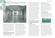
Electro Static Dissipative<br />
(<strong>ESD</strong>) floorcoverings<br />
The <strong>Polyflor</strong> <strong>ESD</strong> family <strong>of</strong> vinyl floorcoverings<br />
consists <strong>of</strong> products which are designed to<br />
meet specific resistance requirements.<br />
The terminology used to describe the various<br />
categories was changed in 1999, as the IEC<br />
brought together the various electronics<br />
industries to ensure that the same terminology<br />
is used by all parties.<br />
Antistatic<br />
These products do not accumulate static charges<br />
above 2.0 KV and are classified as ‘Antistatic’<br />
when tested to EN1815. For specialist application<br />
where there is a requirement to dissipate the<br />
charge, see <strong>Polyflor</strong> <strong>ESD</strong> product ranges.<br />
Static Dissipative (SD)<br />
These products when tested to the test methods<br />
identified in our literature have a resistance to<br />
earth between 1 x 10⁶ and 1 x 10⁹ ohms.<br />
Electrostatic Conductive (EC)<br />
These products when tested to the test methods<br />
identified in our literature have a resistance to<br />
earth between 5 x 10⁴ and 1 x 10⁶ ohms.<br />
<strong>Polyflor</strong> Royal Ordnance Factory (ROF)<br />
These products when tested to the test methods<br />
identified in our literature have a resistance to<br />
earth between zero and 5 x 10⁴ ohms.<br />
8.1 SPECIFYING THE CORRECT PRODUCT<br />
The <strong>Polyflor</strong> <strong>ESD</strong> family <strong>of</strong> products is designed<br />
to minimise or eliminate the risk <strong>of</strong> Electro<br />
Static Discharge (<strong>ESD</strong>) and it is essential that<br />
the correct product be selected for the intended<br />
application. An electrical performance<br />
specification must be identified at the outset.<br />
This will not only stipulate the maximum and<br />
minimum electrical resistance requirements <strong>of</strong><br />
the installed floor, but will also identify the<br />
method <strong>of</strong> test, the electrodes to be used, the<br />
method <strong>of</strong> measurement and the testing<br />
environment.<br />
From this information, the correct <strong>Polyflor</strong> <strong>ESD</strong><br />
product can be identified, taking into account<br />
both the electrical performance and the<br />
method <strong>of</strong> installation. Whenever specifying a<br />
<strong>Polyflor</strong> <strong>ESD</strong> vinyl floorcovering, <strong>Polyflor</strong><br />
strongly recommends that you discuss your<br />
requirements with our Customer Technical<br />
Services Department. They will advise on which<br />
products are best suited for the particular<br />
application, and where no specifıcation has<br />
been identified, will advise on the specifications<br />
used in similar installations/industries.<br />
8.2 ISOLATION OF SUBFLOOR<br />
The electrical conductivity <strong>of</strong> a solid subfloor<br />
can vary greatly, and as a result the installed<br />
floor may have resistances lower than the<br />
minimum stated in the specification.<br />
Cementicious underlayments provide an<br />
isolating barrier <strong>of</strong> known resistance beneath<br />
the vinyl floorcovering.<br />
<strong>Polyflor</strong> recommends that all solid subfloors<br />
should be covered with a cementicious<br />
underlayment which must be at least 3mm<br />
thick. The choice <strong>of</strong> underlayment is dependent<br />
upon the end use location, and consideration<br />
should be given to such properties as point load<br />
resistance and protein content.<br />
The underlayment should be allowed to dry<br />
prior to the application <strong>of</strong> the floorcovering.<br />
<strong>Polyflor</strong> accepts no responsibility for<br />
non-conformance due to the resistance <strong>of</strong> the<br />
installed floor being below the minimum<br />
specified, if an isolating barrier has not<br />
been used.<br />
Note: Suspended timber subfloors are not<br />
conductive and do not require an isolating<br />
barrier.<br />
8.3 CONDUCTIVE ADHESIVES<br />
<strong>Polyflor</strong> recommends the use <strong>of</strong> <strong>Polyflor</strong><br />
conductive adhesive for all Static Control<br />
floorcoverings and <strong>Polyflor</strong> contact adhesive<br />
for earthing strips. If alternative adhesives are<br />
used, they must be recommended by the<br />
adhesive manufacturer and approved by<br />
<strong>Polyflor</strong>.<br />
Note: Access panels vary from manufacturer to<br />
manufacturer, both in design, materials used<br />
and electrical performance specification.<br />
We recommend in these instances that you<br />
discuss your individual requirements with your<br />
panel supplier or alternatively with our<br />
Customer Technical Services Department.<br />
8.4 CONDUCTANCE TO EARTH<br />
Installing an earthing system is a prerequisite<br />
for <strong>ESD</strong> floors. This gives the end user the<br />
option to test to earth should there be a<br />
requirement at a later stage. Secondly,<br />
it improves the conductance <strong>of</strong> the installed<br />
floor to a known earth via a controlled path.<br />
The choice <strong>of</strong> material used for the earthing
system can be brass, copper or stainless steel<br />
and should be nominally 50mm wide and 0.1mm<br />
thick. However, the width is only important for<br />
the “Conductive” floorcovering.<br />
When an earthing system is installed, <strong>Polyflor</strong><br />
recommends the use <strong>of</strong> at least two connections<br />
to earth, the second as a security back-up<br />
should the first be disconnected or damaged.<br />
Connection <strong>of</strong> the earthing system to the<br />
building earth is normally carried out by a<br />
qualified electrician and not the flooring<br />
contractor.<br />
8.4.1 <strong>Polyflor</strong> Static Dissipative (SD)<br />
<strong>Floorcoverings</strong><br />
The earth strip is laid 150mm from one side <strong>of</strong><br />
the room, in the same direction as the vinyl<br />
sheets are to be laid. This strip is connected to<br />
a known earth (Figure 22).<br />
Figure 22 Earthing strip layout<br />
A second strip is laid at 90º to the first, 150mm<br />
from the edge and running across the full width<br />
<strong>of</strong> the room. Further strips are laid at 20 metre<br />
intervals as determined by the size <strong>of</strong> the room.<br />
8.4.2 <strong>Polyflor</strong> Electrostatic Conductive (EC)<br />
<strong>Floorcoverings</strong><br />
A length <strong>of</strong> earth strip is adhered to the<br />
isolating underlayment and connected to a<br />
known earth. The strip need only extend along<br />
the floor for 150mm (Figure 23).<br />
Figure 23 Earth connection<br />
8.4.3 <strong>Polyflor</strong> Conductive <strong>Floorcoverings</strong><br />
With this type <strong>of</strong> flooring, an earthing grid <strong>of</strong><br />
the correct size strip (50mm wide, 0.1mm thick)<br />
is essential. The strips should be laid to form<br />
600mm2 grids across the floor, the perimeter<br />
strips being 150mm from the wall (Figure 24).<br />
At an appropriate point the strip should be<br />
connected to a known earth. It is important that<br />
the layout <strong>of</strong> the grid is confirmed with the end<br />
user as there are variations in the requirement<br />
for some military specifications.<br />
Figure 24 Earthing strip layout<br />
8.5 INSTALLATION METHODS<br />
The basic techniques for installation <strong>of</strong> <strong>Polyflor</strong><br />
<strong>ESD</strong> floorcoverings are the same as described<br />
for standard vinyl sheet and tile in Sections 3<br />
and 4 respectively. However, there are a<br />
number <strong>of</strong> important differences:<br />
8.5.1 <strong>ESD</strong> Vinyl Sheet<br />
<strong>Polyflor</strong> <strong>ESD</strong> vinyl sheet should be installed by<br />
the double drop method. This is because the<br />
conductive adhesive contains carbon, which<br />
results in low tack.<br />
Once the adhesive has been spread, the vinyl<br />
sheet is laid into it and pressed all over to<br />
ensure an even transfer <strong>of</strong> adhesive. The vinyl<br />
sheet is then folded back and left until the<br />
adhesive becomes tacky. When the adhesive is<br />
tacky, the vinyl sheet should be accurately<br />
re-laid, ensuring it does not twist or trap air<br />
bubbles. Seams must be without gaps and any<br />
excess adhesive should be removed as work<br />
proceeds. The vinyl sheet is then rolled with a<br />
68kg articulated floor roller in the short<br />
direction fırst, then the long, and the rolling<br />
repeated between one and four hours later.<br />
8.5.2 <strong>ESD</strong> Vinyl Tiles<br />
<strong>Polyflor</strong> <strong>ESD</strong> vinyl tiles are installed by the<br />
same method as standard vinyl tiles – the single<br />
stick method. The grid layout for static control<br />
tiles is the same as for sheet vinyl, as described<br />
previously.<br />
Note: <strong>ESD</strong> vinyl tiles must always be heat<br />
welded. See Section 11.<br />
8.6 SPECIAL PRECAUTIONS<br />
Special precautions must be taken with the<br />
following products:<br />
8.6.1 Electrostatic Conductive (EC)<br />
<strong>Floorcoverings</strong><br />
Pipes or metal projections (e.g. metal gullies,<br />
door spring plates etc.) must be insulated from<br />
the EC floorcovering and free from conductive<br />
adhesive. The following method <strong>of</strong> installation<br />
is recommended.<br />
The EC floorcovering should be cut 50mm<br />
short <strong>of</strong> any pipe or metal fixture. This infill<br />
area should be laid with a suitably coloured<br />
standard <strong>Polyflor</strong> sheet vinyl, adhered with a<br />
non-conductive adhesive. This infill piece<br />
should then be welded to the <strong>ESD</strong> floorcovering<br />
with a standard weld rod.<br />
8.6.2 Conductive Floorcovering<br />
<strong>Polyflor</strong> Conductive does not provide<br />
protection from a short circuit on a 240/250<br />
volt mains. Where this material is installed, all<br />
electrical equipment and switches must be<br />
located outside the building. No portable<br />
electrical tools should be used inside, unless<br />
earth leakage circuit breakers are fitted to the<br />
switchgear.<br />
8.7 HEAT WELDING<br />
All <strong>Polyflor</strong> <strong>ESD</strong> floorcovering installations<br />
(excluding access panels) must be heat welded.<br />
Ideally, the floor should be left for a minimum<br />
<strong>of</strong> 24 hours before welding the joints. This will<br />
prevent adhesive bubbling up into the seams<br />
when heat is applied. For details <strong>of</strong> heat<br />
welding, see Section 11.<br />
Note: Conductive welding rod is not a<br />
requirement with <strong>Polyflor</strong> <strong>ESD</strong> floorcoverings.<br />
8.8 TEST METHODS<br />
Worldwide, there are a great many test methods<br />
for electrical grade floorcoverings and, with<br />
rapid developments in the electrical and<br />
electronic industries, standards are constantly<br />
being reviewed. To ensure that the floor is<br />
tested to the latest specification, it is suggested<br />
that the architect or specifier should obtain a<br />
copy <strong>of</strong> the test method and requirements from<br />
the local <strong>of</strong>fice <strong>of</strong> the National Standards<br />
Authority. It should then be attached to the<br />
specification prior to the ordering <strong>of</strong> materials<br />
and installation <strong>of</strong> the floor. If a test method is<br />
not specified, the following procedure is
Figure 25 Test electrode<br />
recommended and approved by <strong>Polyflor</strong>.<br />
8.8.1 Test Procedure (BS 61340 -4-1)<br />
The electrical testing <strong>of</strong> the floor must be<br />
carried out with an insulation tester, operating<br />
at 100 volts D.C.<br />
8.8.2 Test Electrodes (BS 61340 -4-1)<br />
The electrode consists <strong>of</strong> a brass cylinder 65mm<br />
in diameter, weighing approximately 2.5 kg.<br />
A screw connector attaches the test lead to the<br />
top surface <strong>of</strong> the cylinder. On the underside is<br />
attached a round rubber pad – <strong>of</strong> 5mm thickness<br />
and 65 mm in diameter – which has been<br />
covered with thin metal foil (Figure 25).<br />
8.8.3 Test Conditioning<br />
It is essential to condition the floor prior to<br />
testing. The floor should be cleaned (see<br />
Section 18.10) at least 24 hours before testing,<br />
and then conditioned for 24 hours at 40-60%<br />
RH and 20-25°C.<br />
Note: The relative humidity and temperature<br />
are only critical for <strong>Polyflor</strong> Static Dissipative<br />
floorcoverings.<br />
8.8.4 Test Method (BS 61340 -4-1)<br />
One electrode should be placed on the floor.<br />
The second connection should be made to the<br />
earth point, the resistance being measured<br />
between the electrode and a known earth.<br />
One test should be made for every 2 square<br />
metres <strong>of</strong> flooring. The test may not be reliable<br />
if made within 24 hours <strong>of</strong> the flooring being<br />
laid or cleaned.<br />
8.8.5 Testing to a Grid<br />
The procedure <strong>of</strong> always testing the same<br />
points “on a grid” is not recommended.<br />
The whole floor should meet the specifıcation,<br />
not just selected points. To ensure continual<br />
performance <strong>of</strong> the whole floor, it should be<br />
periodically tested at random points.<br />
8.8.6 Test Results<br />
<strong>Polyflor</strong> <strong>ESD</strong> floorcoverings are manufactured<br />
to specific levels <strong>of</strong> conductance and are tested,<br />
prior to despatch, in laboratory conditions.<br />
On-site testing not only takes into account the<br />
floorcovering but also the adhesive, the subfloor<br />
and the environment. When installed and tested<br />
in accordance with the instructions laid down<br />
by <strong>Polyflor</strong> and detailed in this manual, the<br />
electrical resistance should be as follows:<br />
MINIMUM AVERAGE MAXIMUM AVERAGE<br />
Static Dissipative 1 x 10⁶ ohms 1 x 10⁹ ohms<br />
Electrostatic Conductive 5 x 10⁴ ohms 1 x 10⁶ ohms<br />
Conductive ROF Zero ohms 5 x 10⁴ ohms<br />
The Customer Technical Services Department<br />
<strong>of</strong>fers, for a fee, a finished installation testing<br />
service – to ensure that the whole installation<br />
meets the specification requirements.<br />
A Certificate <strong>of</strong> Conformance is issued on<br />
completion. We recommend that you discuss<br />
your testing requirements with our Customer<br />
Technical Services team, to ascertain staff<br />
availability etc.<br />
8.9 STATIC CONTROL SYSTEMS<br />
In many instances, a <strong>Polyflor</strong> <strong>ESD</strong> floorcovering<br />
is sufficient to give the necessary control,<br />
but in highly static-sensitive areas, additional<br />
precautions may be necessary.<br />
These include:<br />
Dissipative clothing and footwear<br />
Wrist and heel straps<br />
Special work stations<br />
Dissipative packaging and sealing<br />
Ionisers and humidity controllers<br />
EARTH TEST RESULTS