Principles of Digital Radiography with Large-Area, Electronically ...
Principles of Digital Radiography with Large-Area, Electronically ...
Principles of Digital Radiography with Large-Area, Electronically ...

You also want an ePaper? Increase the reach of your titles
YUMPU automatically turns print PDFs into web optimized ePapers that Google loves.
Harrell G. Chotas, MS<br />
James T. Dobbins III, PhD<br />
Carl E. Ravin, MD<br />
Index terms:<br />
<strong>Radiography</strong>, digital, * .121 2<br />
<strong>Radiography</strong>, direction conversion<br />
<strong>Radiography</strong>, indirect conversion<br />
<strong>Radiography</strong>, selenium detector,<br />
* .121<br />
<strong>Radiography</strong>, technology<br />
Radiology 1999; 210:595–599<br />
Abbreviation:<br />
CCD charged-coupled device<br />
1 From the Departments <strong>of</strong> Radiology,<br />
<strong>Digital</strong> Imaging Research Division<br />
(H.G.C., J.T.D., C.E.R.), and Biomedical<br />
Engineering (J.T.D.), Duke University<br />
Medical Center, Box 3302, Rm 139,<br />
Bryan Research Bldg, Research Dr,<br />
Durham, NC 27710. Received February<br />
24, 1998; revision requested April<br />
2; final revision received July 7; accepted<br />
September 11. Address reprint<br />
requests to H.G.C.<br />
2<br />
* . Multiple body systems<br />
RSNA, 1999<br />
Review<br />
<strong>Principles</strong> <strong>of</strong> <strong>Digital</strong><br />
<strong>Radiography</strong> <strong>with</strong> <strong>Large</strong>-<strong>Area</strong>,<br />
<strong>Electronically</strong> Readable<br />
Detectors: A Review <strong>of</strong><br />
the Basics 1<br />
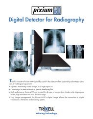
The practice <strong>of</strong> digital radiographic imaging is poised to undergo dramatic change in the<br />
very near future owing to a rapid proliferation <strong>of</strong> electronically readable x-ray detectors.<br />
Although self-scanning, direct-readout digital detectors have been in use since the<br />
introduction <strong>of</strong> the charged-coupled device (CCD) almost 30 years ago, recent advances in<br />
manufacturing technology have made possible a new generation <strong>of</strong> large-area, flat-panel<br />
detectors <strong>with</strong> integrated, thin-film transistor readout mechanisms. The excitement<br />
surrounding this new technology is based on two factors—the promise <strong>of</strong> very rapid access<br />
to digital images wherever radiography <strong>with</strong> stationary x-ray equipment is performed and<br />
the anticipation <strong>of</strong> image quality that exceeds that <strong>of</strong> both screen-film receptors and<br />
photostimulable storage phosphor computed radiographic systems because <strong>of</strong> improvements<br />
in x-ray detector technology.<br />
As digital radiography continues this rapid evolution, it is likely that radiologists will be<br />
inundated <strong>with</strong> information concerning a wide variety <strong>of</strong> large-area, flat-panel electronic<br />
detectors. Unfortunately, it is also likely that there will be a tendency to think <strong>of</strong> these<br />
devices as equivalent, interchangeable commodities because they will be similar in physical<br />
size, appearance, and targeted applications. It must be emphasized, however, that<br />
important differences exist among these detectors, and differences in digital image quality<br />
among the various systems are inevitable and may be quite large. To minimize confusion,<br />
therefore, it is important that radiologists have a working understanding <strong>of</strong> this emerging<br />
technology.<br />
In this report, we provide an overview <strong>of</strong> digital electronic x-ray detectors, including two<br />
broad classes <strong>of</strong> detectors based on thin-film transistor arrays and the older, CCD-based<br />
designs. Computed radiographic systems based on photostimulable storage phosphors are<br />
omitted from this report because they do not contain integrated readout mechanisms (1).<br />
Our goal is to provide a brief review <strong>of</strong> the basic methods, designs, and materials used in<br />
direct-readout radiographic systems and to emphasize important characteristics that may<br />
affect system performance and image quality. The advantages and disadvantages <strong>of</strong> the<br />
different detectors, as well as the important factors that should be considered when<br />
performing a critical analysis <strong>of</strong> these new digital imaging systems, are discussed.<br />
DIRECT VERSUS INDIRECT CONVERSION<br />
Electronic x-ray detectors can be divided into two classes—those in which direct methods<br />
are used to convert x rays into an electric charge and those in which indirect methods are<br />
used (Fig 1). (‘‘Direct conversion’’ should not be confused <strong>with</strong> ‘‘direct readout,’’ which is a<br />
capability <strong>of</strong> all electronic detectors.) Direct-conversion detectors have an x-ray photoconductor,<br />
such as amorphous selenium, that directly converts x-ray photons into an electric<br />
charge. Indirect-conversion detectors, on the other hand, have a two-step process for x-ray<br />
detection; a scintillator is the primary material for x-ray interaction. When x rays strike the<br />
scintillator, the x-ray energy is converted into visible light, and that light is then converted<br />
into an electric charge by means <strong>of</strong> photodetectors such as amorphous silicon photodiode<br />
arrays or CCDs. In both direct- and indirect-conversion detectors, the electric charge<br />
pattern that remains after x-ray exposure is sensed by an electronic readout mechanism,<br />
and analog-to-digital conversion is performed to produce the digital image.<br />
595
LARGE-AREA, THIN-FILM<br />
TRANSISTOR ARRAYS<br />
Recent advances in photolithography and<br />
electronic micr<strong>of</strong>abrication techniques<br />
have enabled the development <strong>of</strong> largearea<br />
x-ray detectors <strong>with</strong> integrated readout<br />
mechanisms based on arrays <strong>of</strong> thinfilm<br />
transistors. Unlike older, CCD-based<br />
detectors that require optical coupling<br />
and image demagnification (discussed<br />
later), thin-film transistor–based, flatpanel<br />
systems are constructed such that<br />
the pixel charge collection and readout<br />
electronics for each pixel are immediately<br />
adjacent to the site <strong>of</strong> the x-ray interactions.<br />
Several investigators (2,3) have<br />
reported prototypic thin-film transistor–<br />
based systems <strong>with</strong> x-ray–sensitive elements<br />
that achieve detective quantum<br />
efficiencies <strong>of</strong> 65% or more; this greatly<br />
exceeds the performance <strong>of</strong> photostimulable<br />
storage phosphor systems, which<br />
have efficiencies <strong>of</strong> 20%–35% (4), and<br />
<strong>of</strong> screen-film systems for chest radiography,<br />
which have nominal efficiencies<br />
<strong>of</strong> 25% (5), and is comparable to the<br />
performance <strong>of</strong> a commercial seleniumdrum<br />
digital chest radiographic system<br />
(6).<br />
Thin-film transistor arrays are used as<br />
the active electronic elements in both<br />
indirect- and direct-conversion, flat-panel<br />
detectors. Thin-film transistor arrays are<br />
typically deposited onto a glass substrate<br />
in multiple layers, beginning <strong>with</strong> readout<br />
electronics at the lowest level and<br />
followed by charge collector arrays at<br />
higher levels. Then, depending on the<br />
type <strong>of</strong> detector being constructed, x-ray<br />
elements, light-sensitive elements, or<br />
both, are deposited to form the top layer<br />
<strong>of</strong> this ‘‘electronic sandwich,’’ and the<br />
entire assembly is encased in a protective<br />
enclosure <strong>with</strong> external cabling for computer<br />
connection.<br />
THIN-FILM TRANSISTOR-DIRECT<br />
CONVERSION<br />
Direct-conversion systems based on thinfilm<br />
transistor arrays are constructed by<br />
adding an x-ray photoconductor as the<br />
top layer <strong>of</strong> the electronic thin-film transistor<br />
sandwich (Fig 2). Typically, amorphous<br />
selenium is used as the photoconductor<br />
material because <strong>of</strong> its excellent<br />
x-ray detection properties (6–8) and extremely<br />
high intrinsic spatial resolution<br />
( 20 line pairs per millimeter [lp/mm] at<br />
100 keV) (9). Before exposure, an electric<br />
field is applied across the amorphous<br />
Figure 1. Direct-readout electronic x-ray detectors use either a direct technique or an indirect<br />
technique for converting x rays into an electric charge. Direct-conversion detectors have an x-ray<br />
photoconductor, such as amorphous selenium, that converts x-ray photons into an electric charge<br />
directly, <strong>with</strong> no intermediate stage. Indirect-conversion devices have a scintillator that first<br />
converts x rays into visible light. That light is then converted into an electric charge by using an<br />
amorphous silicon photodiode array or a CCD. Thin-film transistor (TFT) arrays may be used in<br />
both direct- and indirect-conversion detectors.<br />
Figure 2. Direct-conversion thin-film transistor detectors use a uniform layer <strong>of</strong> evaporated<br />
amorphous selenium to convert x rays into electron-hole pairs. Electric fields that are established<br />
<strong>with</strong>in the selenium by means <strong>of</strong> bias voltages channel the charge to the nearest collector,<br />
which preserves spatial resolution. Very high fill factors are achievable <strong>with</strong> appropriate electrode<br />
design.<br />
selenium layer through a bias electrode<br />
on the top surface <strong>of</strong> the selenium. As x<br />
rays are absorbed in the detector, electrons<br />
and holes are released <strong>with</strong>in the<br />
selenium, and owing to the electric field<br />
<strong>with</strong>in the selenium, electric charges are<br />
drawn directly to the charge-collecting<br />
electrodes. Pixels are effectively separated<br />
by means <strong>of</strong> field shaping <strong>with</strong>in the<br />
selenium layer, and the entire selenium<br />
surface is available for x-ray charge conversion.<br />
Thus, <strong>with</strong> properly designed charge-<br />
collection electrodes, effective fill factors approaching<br />
100% are achievable (3,10).<br />
Amorphous selenium is well developed<br />
technologically; it has been used for decades<br />
as a photoconductor in photocopiers<br />
and in an x-ray imaging technique<br />
known as xeroradiography (11,12).<br />
Because selenium is used in its amorphous<br />
form, selenium plates can be<br />
made by means <strong>of</strong> evaporation and thus<br />
can be made relatively easily and inexpensively.<br />
596 • Radiology • March 1999 Chotas et al
Figure 3. In indirect-conversion detectors, the x-ray scintillator can be structured or unstructured.<br />
Structured scintillators, which typically are crystalline cesium iodide, reduce the spread <strong>of</strong><br />
visible light; this improves spatial resolution and permits the use <strong>of</strong> thicker scintillator materials<br />
for improved quantum detection.<br />
THIN-FILM<br />
TRANSISTOR-INDIRECT<br />
CONVERSION<br />
Indirect-conversion systems based on<br />
thin-film transistor arrays are constructed<br />
by adding amorphous silicon photodiode<br />
circuitry and a scintillator as the top<br />
layers <strong>of</strong> the thin-film transistor sandwich.<br />
These layers replace the x-ray photoconductor<br />
layer that is used in directconversion<br />
devices. When x rays strike<br />
the scintillator, visible light is emitted<br />
proportional to the incident x-ray energy.<br />
Visible light photons are then converted<br />
into an electric charge by the photodiode<br />
array, and the charge collected at each<br />
photodiode is converted into a digital<br />
value by using the underlying readout<br />
electronics.<br />
The scintillators used in indirect-conversion<br />
detectors can be either structured<br />
or unstructured (Fig 3). With an unstructured<br />
scintillator, such as conventional<br />
fluorescent screens, visible light that is<br />
emitted in the material can spread to<br />
adjacent pixels and thereby reduce spatial<br />
resolution. To reduce this problem, some<br />
manufacturers now use a structured scintillator<br />
that consists <strong>of</strong> cesium iodide<br />
crystals that are grown on the detector.<br />
The crystalline structure, which consists<br />
<strong>of</strong> discrete and parallel ‘‘needles’’ approximately<br />
5–10 µm wide, behaves similar to<br />
a bundle <strong>of</strong> light pipes and channels most<br />
<strong>of</strong> the signal directly to the photodiode<br />
layer. Because light spreading is greatly<br />
reduced in a structured scintillator, thicker<br />
layers <strong>of</strong> this material can be used in the<br />
detector; this increases the number <strong>of</strong><br />
x-ray photon interactions and thus the<br />
available visible light. Although there are<br />
trade-<strong>of</strong>fs and practical limitations to this<br />
approach (13), use <strong>of</strong> thicker layers <strong>of</strong><br />
structured scintillators greatly increases<br />
the potential detective quantum efficiency<br />
that is achievable by using the<br />
detector, especially at higher imaging frequencies.<br />
For this reason and because <strong>of</strong><br />
its high x-ray absorption efficiency, most<br />
manufacturers <strong>of</strong> indirect detector systems<br />
appear to be moving toward the use<br />
<strong>of</strong> structured cesium iodide scintillator<br />
materials.<br />
CHARGED-COUPLED DEVICES<br />
The basic CCD consists <strong>of</strong> a series <strong>of</strong><br />
metal-oxide-semiconductor capacitors<br />
that are fabricated very close together on<br />
a semiconductor surface. Originally invented<br />
by Bell Laboratories in 1969 in an<br />
effort to create new computer memory<br />
devices, CCDs were quickly adapted for<br />
use as photodetectors when their sensitivity<br />
to visible light was recognized. Today,<br />
CCDs are used in a wide variety <strong>of</strong> indirect-conversion<br />
x-ray imaging devices, including<br />
large-area radiographic imaging<br />
systems and the familiar image-intensifier<br />
television system that is used in fluoroscopy.<br />
The single most salient characteristic <strong>of</strong><br />
CCDs <strong>with</strong> regard to digital radiography<br />
is that they are physically small—typically<br />
2–4 cm 2 , which is much smaller<br />
than typical projected x-ray areas. Because<br />
<strong>of</strong> this, cost-effective CCD-based<br />
radiographic systems must include some<br />
means <strong>of</strong> optical coupling to reduce the<br />
size <strong>of</strong> the projected visible light image<br />
and transfer the image to the face <strong>of</strong> one<br />
or more CCDs. Some CCD-based systems<br />
have an image intensifier that reduces the<br />
large x-ray field to the size <strong>of</strong> one CCD.<br />
Other systems are based on an array <strong>of</strong><br />
CCD cameras, each <strong>of</strong> which is coupled to<br />
a scintillator by a lens or a fiberoptic<br />
taper. The lens system substantially reduces<br />
the number <strong>of</strong> photons that reach<br />
the CCD; this increases the appearance <strong>of</strong><br />
image noise (ie, quantum mottle) and<br />
degrades image quality. In addition, optical<br />
coupling <strong>with</strong> lenses can introduce<br />
geometric distortions, optical scatter, and<br />
reduced spatial resolution. Fiberoptic<br />
tapers can be used in place <strong>of</strong> optical lens<br />
systems to mitigate light loss and optical<br />
scatter problems to some degree, but imperfections<br />
in the optical fiber bundles<br />
can introduce structure artifacts on the<br />
image. Finally, thermal noise <strong>with</strong>in the<br />
CCD itself also can degrade image quality,<br />
although this is less <strong>of</strong> a factor <strong>with</strong><br />
modern, cooled CCDs.<br />
SYSTEM CONSIDERATIONS<br />
If recent pr<strong>of</strong>essional radiology conferences<br />
are any indication, numerous digital<br />
radiographic systems based on directreadout,<br />
flat-panel x-ray detectors will<br />
soon be available commercially. Because<br />
all <strong>of</strong> these detectors are compact, electronically<br />
readable devices that <strong>of</strong>fer rapid<br />
image capture and direct connection to<br />
computers in an imaging network, it may<br />
appear to many radiologists that they are<br />
equivalent, interchangeable commodities.<br />
As indicated previously, this is not<br />
the case.<br />
Generally speaking, it is our opinion<br />
that digital radiographic systems based<br />
on thin-film transistor arrays will ultimately<br />
provide superior image quality<br />
relative to CCD-based detectors, particularly<br />
when large-area detectors are required.<br />
This is owing principally to the<br />
requirement <strong>of</strong> CCD systems for either<br />
image demagnification or a more costly<br />
design <strong>with</strong> many tiled CCDs. In comparing<br />
systems based on thin-film transistor<br />
arrays, however, it is not yet clear whether<br />
direct-conversion or indirect-conversion<br />
designs will ultimately provide the preferred<br />
solution. It may well be that optimum<br />
system selection will depend on the<br />
intended application (eg, static imaging<br />
or fluoroscopy), although it is premature<br />
to make such a determination at this<br />
time.<br />
Evaluation and selection <strong>of</strong> a digital<br />
radiographic system should involve a<br />
thorough analysis <strong>of</strong> the complete imaging<br />
system, including the x-ray detector<br />
itself and the environment in which the<br />
Volume 210 • Number 3 Review <strong>of</strong> <strong>Principles</strong> <strong>of</strong> <strong>Digital</strong> <strong>Radiography</strong> • 597
system will be used. The following considerations<br />
are <strong>of</strong>fered to facilitate the evaluation<br />
<strong>of</strong> electronic digital radiographic<br />
systems.<br />
Detector Size<br />
The physical dimensions <strong>of</strong> the x-ray<br />
detector have an obvious influence on<br />
the radiographic examinations performed,<br />
and it is critical that the detector<br />
be both sufficiently large to capture the<br />
desired anatomic views and sufficiently<br />
compact for the desired applications. Electronic<br />
detectors for standing radiographic<br />
examinations, for example, would ideally<br />
have an active detector that is at least<br />
43 43 cm (ie, 17 17 inches) in size to<br />
allow both vertical (35 43-cm) and<br />
horizontal (43 35-cm) imaging orientations<br />
<strong>with</strong>out detector rotation. With<br />
good mechanical design, a rectangular<br />
35 43-cm (ie, 14 17-inch) detector<br />
that can be easily rotated may perform as<br />
well as a larger detector.<br />
Spatial Resolution<br />
Image spatial resolution, <strong>of</strong>ten expressed<br />
as the modulation transfer function,<br />
can vary substantially, depending<br />
on physical detector characteristics. The<br />
intrinsic spatial resolution <strong>of</strong> amorphous<br />
selenium (<strong>with</strong> direct conversion) and <strong>of</strong><br />
structured cesium iodide (<strong>with</strong> indirect<br />
conversion) is higher than that <strong>of</strong> unstructured<br />
scintillators, and the intrinsic resolution<br />
<strong>of</strong> selenium is much higher. <strong>Digital</strong><br />
images can be processed to alter apparent<br />
image sharpness; however, excessive processing<br />
can lead to an increase in perceived<br />
noise. Thus, the inherent detector<br />
modulation transfer function, when expressed<br />
as a function <strong>of</strong> spatial frequency,<br />
is not as useful as a measure <strong>of</strong> overall<br />
system performance as is the detective<br />
quantum efficiency. (See the Image Quality<br />
section that follows.)<br />
Image Quality<br />
Although observer studies are the most<br />
conclusive methods <strong>of</strong> determining overall<br />
system performance, the difficulty in<br />
performing such studies for all clinical<br />
detection tasks makes it desirable to find<br />
a more suitable physical measurement<br />
that gives an indication <strong>of</strong> overall system<br />
performance. Although there is no physical<br />
measurement that correlates perfectly<br />
<strong>with</strong> perceived diagnostic quality, and<br />
there are unique difficulties associated<br />
<strong>with</strong> physical image assessment in digital<br />
systems (14), detective quantum efficiency<br />
is generally accepted as the best<br />
single objective indicator <strong>of</strong> image fidelity.<br />
Detective quantum efficiency combines<br />
spatial resolution (ie, modulation<br />
transfer function) and image noise (ie,<br />
noise power spectrum) to provide a measure<br />
<strong>of</strong> the signal-to-noise ratio <strong>of</strong> the<br />
various frequency components <strong>of</strong> the image.<br />
Higher detective quantum efficiency<br />
values suggest greater image quality, and<br />
the results should be evaluated at all<br />
frequencies to estimate the ability <strong>of</strong> the<br />
image to depict both small and large<br />
image structures.<br />
Pixel Size and Matrix Size<br />
The maximum spatial resolution on an<br />
image is defined by pixel size and spacing<br />
(ie, pitch). It should be emphasized, however,<br />
that more pixels do not always<br />
mean higher spatial resolution, because<br />
image blurring can result from x-ray scatter,<br />
light scatter, or both, in the detector.<br />
For chest radiography, some investigators<br />
(15,16) have concluded that 0.2-mm pixel<br />
spacing (2.5 lp/mm, approximately 2,000<br />
pixels per row) is adequate for most diagnostic<br />
tasks, and in one commercial selenium-drum<br />
digital chest radiographic system,<br />
these 2K images have been reported<br />
to <strong>of</strong>fer superior depiction <strong>of</strong> anatomic<br />
structures and an image appearance that<br />
is preferred over that <strong>of</strong> conventional<br />
screen-film radiographs. For mammography,<br />
smaller pixel sizes—probably in the<br />
range <strong>of</strong> 50–100 µm per pixel—are required.<br />
Although some detectors that <strong>of</strong>fer<br />
substantially higher pixel pitch will<br />
soon be available, it should be remembered<br />
that the advantages that may be<br />
gained by using larger image matrices<br />
also have implications in practical implementation,<br />
including increased network<br />
traffic, increased archiving requirements,<br />
and the likely need for image reduction<br />
when images are displayed on video<br />
monitors.<br />
Monolithic Panels versus Tiled<br />
Arrays<br />
Because fabrication <strong>of</strong> full-size thinfilm<br />
transistor detector panels is technically<br />
challenging and can have relatively<br />
low yields, many manufacturers seek to<br />
reduce costs by constructing detectors<br />
that consist <strong>of</strong> two or more smaller panels<br />
in a tiled configuration. In these detectors,<br />
digital image processing is used to<br />
‘‘stitch together’’ the image sections to<br />
eliminate the appearance <strong>of</strong> the tile junc-<br />
tions. Although attractive in concept, this<br />
approach can be problematic in that it is<br />
difficult to seamlessly reconstruct a complete<br />
image <strong>with</strong>out compromising image<br />
quality (17). In addition, the effects <strong>of</strong><br />
physical and thermal stress on the longterm<br />
structural integrity <strong>of</strong> tiled detectors<br />
has not yet been determined.<br />
Bad Pixels and Rows<br />
Perfect thin-section transistor arrays are<br />
difficult to make, so practical limits <strong>with</strong><br />
regard to the number <strong>of</strong> defects allowed<br />
in these devices must be established by<br />
each manufacturer. Defects may manifest<br />
as individual bad pixels or entire bad<br />
pixel columns or rows. Image corrections<br />
made by using system calibration masks<br />
and additional image processing can ameliorate<br />
some <strong>of</strong> these defects; however, as<br />
<strong>with</strong> detector tiling, one must exercise<br />
caution so that the image processing does<br />
not alter the image in ways that adversely<br />
affect the diagnosis.<br />
Image Acquisition Time and Rate<br />
The image quality <strong>with</strong> electronic detectors<br />
is influenced by the details <strong>of</strong> circuit<br />
design for charge collection, the charge<br />
measurement technique, the analog-todigital<br />
conversion rates during readout,<br />
and in some detectors, the device recharging<br />
between exposures. Generally, electronic<br />
noise is the predominant noise<br />
source in these detectors and the factor<br />
that limits image quality, particularly at<br />
the low-dose rates associated <strong>with</strong> fluoroscopy.<br />
Whether one is performing fluoroscopy<br />
or static radiographic imaging, the<br />
precision <strong>of</strong> a pixel value (ie, the number<br />
<strong>of</strong> gray levels) is related to the readout<br />
time, <strong>with</strong> longer times generally resulting<br />
in more precise image values. Because<br />
image readout involves the active flow <strong>of</strong><br />
the current to and from each pixel element,<br />
an incomplete charge transfer can<br />
lead to inaccurate pixel values later if a<br />
subsequent exposure is used <strong>with</strong>out taking<br />
the residual charge into account; the<br />
result is an electronic memory artifact.<br />
Similarly, rapid image acquisition can also<br />
lead to image artifacts owing to x-ray–<br />
induced charge trapping (18,19); however,<br />
compensation for this effect may be<br />
designed into the readout electronics <strong>of</strong><br />
the detector (20,21). For these reasons,<br />
not all thin-film transistor system designs<br />
are practical for use where high exposure<br />
levels or high-speed image acquisition is<br />
required (eg, in fluoroscopy); this factor<br />
should be considered when selecting a<br />
digital detector and how it will be used.<br />
598 • Radiology • March 1999 Chotas et al
Dynamic Range<br />
One <strong>of</strong> the principal advantages <strong>of</strong><br />
digital radiography is that image acquisition<br />
and image display are decoupled;<br />
this allows the detector to have a wide<br />
dynamic range and linear response to<br />
x-ray exposure. Radiologists should be<br />
aware, however, that for a given analog-todigital<br />
converter (ie, a given pixel depth),<br />
there can be a trade-<strong>of</strong>f between the detector’s<br />
sensitivity range (ie, latitude) and<br />
contrast resolution (ie, bits per pixel), and<br />
some manufacturers may choose to limit<br />
the dynamic range <strong>of</strong> the detector to<br />
maximize the number <strong>of</strong> gray values on<br />
the digital image. If used <strong>with</strong> an automatic<br />
exposure control mechanism (ie,<br />
phototimer), however, even detector<br />
systems <strong>with</strong> limited latitude (ie, two<br />
to three decades) should have no operational<br />
problems in clinical use, because<br />
the photodetector will ensure that the<br />
exposure is appropriate for the available<br />
dynamic range. If no phototimer is incorporated<br />
into the system, it is recommended<br />
that the detector have a minimum <strong>of</strong> four<br />
decades <strong>of</strong> latitude, equivalent to the latitude<br />
<strong>of</strong> photostimulable storage phosphor<br />
systems, to avoid data loss owing to<br />
overexposure or underexposure.<br />
Antiscatter Grid<br />
Any digital imaging system that includes<br />
an antiscatter grid has the potential<br />
for interaction between the grid lines<br />
(ie, lead septa) and the rows <strong>of</strong> pixels that<br />
constitute the digital image. For example,<br />
grid line artifacts <strong>of</strong>ten manifest in a<br />
‘‘corduroy pattern’’ <strong>of</strong> lines on the image<br />
owing to image aliasing; however, some<br />
high-strip-count grids do not leave apparent<br />
grid lines on digital images. Artifacts<br />
that can be produced by grid interaction<br />
are not always obvious and can degrade<br />
image quality, so caution and proper selection<br />
<strong>of</strong> the grid is advised.<br />
CONCLUSION<br />
<strong>Electronically</strong> readable, large-area x-ray<br />
detectors that promise rapid access to the<br />
image for diagnosis, improved image quality<br />
relative to that <strong>of</strong> screen-film and<br />
storage phosphor–based radiography, reduced<br />
patient examination time, a reduction<br />
<strong>of</strong> consumable agents, and possibilities<br />
for reduced patient exposure will<br />
soon be commercially available for digital<br />
radiography. While these devices will certainly<br />
create many new opportunities in<br />
diagnostic imaging, it is critical that radiologists<br />
recognize that these new selfscanning<br />
digital radiographic systems are<br />
not interchangeable commodities and<br />
can, in fact, produce images <strong>with</strong> very<br />
different image quality.<br />
References<br />
1. Sonoda M, Takano M, Miyahara J, Kato H.<br />
Computed radiography utilizing scanning<br />
laser stimulated luminescence. Radiology<br />
1983; 148:833–838.<br />
2. Siewerdsen JH, Antonuk LE, el-Mohri Y, et<br />
al. Empirical and theoretical investigation<br />
<strong>of</strong> the noise performance <strong>of</strong> indirect detection,<br />
active matrix flat-panel imagers (AM-<br />
FPIs) for diagnostic radiology. Med Phys<br />
1997; 24:71–89.<br />
3. Zhao W, Rowlands JA. <strong>Digital</strong> radiology<br />
using active matrix readout <strong>of</strong> amorphous<br />
selenium: theoretical analysis <strong>of</strong> detective<br />
quantum efficiency. Med Phys 1997; 24:<br />
1819–1833.<br />
4. Dobbins JT, Ergun DL, Rutz L, Hinshaw<br />
DA, Blume H, Clark DC. DQE(f) <strong>of</strong> four<br />
generations <strong>of</strong> computed radiography acquisition<br />
devices. Med Phys 1995; 22:<br />
1581–1593.<br />
5. Bunch PC. Performance characteristics <strong>of</strong><br />
asymmetric zero-crossover screen-film systems.<br />
Proc SPIE 1992; 1653:46–65.<br />
6. Neitzel U, Maack I, Gunther-Kohfahl S.<br />
Image quality <strong>of</strong> a digital chest radiography<br />
system based on a selenium detector.<br />
Med Phys 1994; 21:509–516.<br />
7. Papin PJ, Huang HK. A prototype amorphous<br />
selenium imaging plate system for<br />
digital radiography. Med Phys 1987; 14:<br />
322–329.<br />
8. Fahrig R, Rowlands JA, Yaffe MJ. X-ray<br />
imaging <strong>with</strong> amorphous selenium: detec-<br />
tive quantum efficiency <strong>of</strong> photoconductive<br />
receptors for digital mammography.<br />
Med Phys 1995; 22:153–160.<br />
9. Que W, Rowlands JA. X-ray imaging using<br />
amorphous selenium: inherent spatial<br />
resolution. Med Phys 1995; 22:365–74.<br />
10. Rowlands JA, Zhao W, Blevis I, Pang G, Ji<br />
WG, Germann S. Flat panel detector for<br />
digital radiology using active matrix readout<br />
<strong>of</strong> amorphous selenium. Proc SPIE<br />
1997; 3032:97–108.<br />
11. Boag JW. Xeroradiography. Phys Med Biol<br />
1973; 18:3–37.<br />
12. Paulus DD. Xeroradiography: an in-depth<br />
review. Crit Rev Diagn Imaging 1980;<br />
12:309–384.<br />
13. Chabbal J, Chaussat C, Ducourant T, et al.<br />
Amorphous silicon x-ray image sensor.<br />
Proc SPIE 1996; 2708:499–510.<br />
14. Dobbins JT. Effects <strong>of</strong> undersampling on<br />
the proper interpretation <strong>of</strong> modulation<br />
transfer function, noise power spectra,<br />
and noise equivalent quanta <strong>of</strong> digital<br />
imaging systems. Med Phys 1995; 22:171–<br />
181.<br />
15. Floyd C Jr, Baker JA, Chotas HG, Delong<br />
DM, Ravin CE. Selenium-based digital<br />
radiography <strong>of</strong> the chest: radiologists’ preference<br />
compared <strong>with</strong> film-screen radiographs.<br />
AJR 1995; 165:1353–1358.<br />
16. Woodard PK, Slone RM, Gierada DS, Reiker<br />
GG, Pilgram TK, Jost RG. Chest radiography:<br />
depiction <strong>of</strong> normal anatomy<br />
and pathologic structures <strong>with</strong> seleniumbased<br />
digital radiography versus conventional<br />
screen-film radiography. Radiology<br />
1997; 203:197–201.<br />
17. Slump CH, van Dijk PW, Laanstra G, et al.<br />
Real-time diagnostic imaging <strong>with</strong> a novel<br />
x-ray detector <strong>with</strong> multiple screen-CCD<br />
sensors. Proc SPIE 1999; 3336:418–429.<br />
18. Chotas HG, Floyd C Jr, Ravin CE. Memory<br />
artifact related to selenium-based digital<br />
radiography systems. Radiology 1997; 203:<br />
881–883.<br />
19. Kasap SO, Aiyah V. X-ray induced hole<br />
trapping in electroradiographic plates. J<br />
Appl Phys 1991; 69:7087–7096.<br />
20. Zhao W, Blevis I, Germann S, Rowlands<br />
JA, Waechter D, Huang Z. <strong>Digital</strong> radiology<br />
using active matrix readout <strong>of</strong> amorphous<br />
selenium: construction and evaluation<br />
<strong>of</strong> a prototype real-time detector.<br />
Med Phys 1997; 24:1834–1843.<br />
21. Tsukamoto A, Yamada S, Tomisaki T, et al.<br />
Development <strong>of</strong> a selenium-based flatpanel<br />
detector for real-time radiography<br />
and fluoroscopy. Proc SPIE 1999; 3336:<br />
388–395.<br />
Volume 210 • Number 3 Review <strong>of</strong> <strong>Principles</strong> <strong>of</strong> <strong>Digital</strong> <strong>Radiography</strong> • 599