- Page 1:
UNIVERSITE DE LIMOGES ECOLE DOCTORA
- Page 5 and 6:
Acknowledgments En préambule à ce
- Page 7 and 8:
Summary ACKNOWLEDGMENTS ...........
- Page 9 and 10:
V. A PERSPECTIVE FOR FUTURE DEVELOP
- Page 11 and 12:
French Introduction Les signaux TV
- Page 13 and 14:
I. Introduction to TV tuners and to
- Page 15 and 16:
I.1.b.ii Digital modulations In dig
- Page 17 and 18:
makes the covering of a large terri
- Page 19 and 20:
I.1.c.iii Terrestrial spectrum Firs
- Page 21 and 22:
I.1.e Broadband Reception Systems F
- Page 23 and 24:
I.2.b TV Tuner High Performance Spe
- Page 25 and 26:
I.2.b.ii High linearity Although co
- Page 27 and 28:
I.3 RF Filter Specifications I.3.a
- Page 29 and 30:
27. This leads to the downconversio
- Page 31 and 32:
These adjacent channel rejection re
- Page 33 and 34:
Above 870MHz, there are no more ter
- Page 35 and 36:
Newest silicon tuners generations,
- Page 37 and 38:
I.6 References [I.1] B. Razavi, RF
- Page 39 and 40:
II. Challenges of RF Selectivity Fo
- Page 41 and 42:
Figure 39. H3 and N+5 rejections of
- Page 43 and 44:
Figure 43. Second order Low-pass Fi
- Page 45 and 46:
Figure 46 illustrates the transfer
- Page 47 and 48: H HPF s ( s) = s 1 + ω This corres
- Page 49 and 50: Topologies comparison for a same Q-
- Page 51 and 52: Figure 56. Low-pass to Notch Transf
- Page 53 and 54: II.2 Passive LC Second Order Bandpa
- Page 55 and 56: A possible solution is to split the
- Page 57 and 58: II.2.c Second Order Bandpass Filter
- Page 59 and 60: Figure 69. Band Switching Figure 70
- Page 61 and 62: Another paper [II.7] provides a FOM
- Page 63 and 64: A parallel self resonating circuit
- Page 65 and 66: This gives the following values for
- Page 67 and 68: Vb - 63 - M1 M2 Zin Figure 76. Anot
- Page 69 and 70: when given, reported noise figures
- Page 71 and 72: In all publications dedicated to Gm
- Page 73 and 74: II.4.c Second Order Bandpass Filter
- Page 75 and 76: Figure 87. Biquad Schematic The Gm-
- Page 77 and 78: Vin Rm - 73 - C Vout Figure 89. Der
- Page 79 and 80: Figure 93 depicts the RF performanc
- Page 81 and 82: A second advantage of advanced BiCM
- Page 83 and 84: II.7 Conclusion As a conclusion, th
- Page 85 and 86: [II.13] C. Andriesei, L. Goras, and
- Page 87 and 88: III.I Theoretical Study III. Gm-C F
- Page 89 and 90: g V m3 in III.1.b Linearity Conside
- Page 91 and 92: Assuming an ideal input transconduc
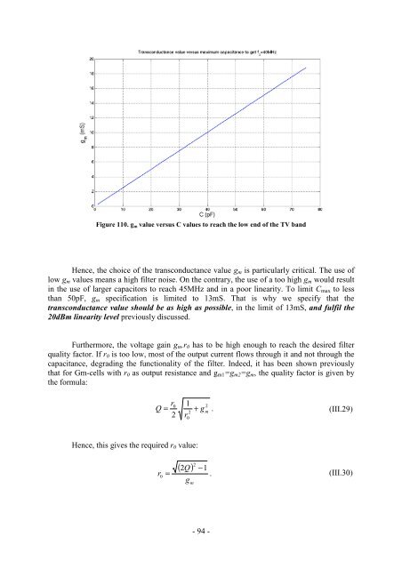
- Page 93 and 94: Figure 102. Linearity of the filter
- Page 95 and 96: Furthermore, a Gm-C circuit is not
- Page 97: In terms of noise, the Flicker nois
- Page 101 and 102: Idiff (A) levels reached with this
- Page 103 and 104: III.2.e Unbalanced Differential Pai
- Page 105 and 106: Hence, the combination of the expon
- Page 107 and 108: Technique Current Increase Source D
- Page 109 and 110: Using this structure and considerin
- Page 111 and 112: The dimensioning of the transistors
- Page 113 and 114: III.3.c Gm-cells with MGTR III.3.c.
- Page 115 and 116: Furthermore, the high sensitivity t
- Page 117 and 118: Figure 136. Filter in-band IIP3 ver
- Page 119 and 120: III.4 Comparison of the filters III
- Page 121 and 122: III.5 Conclusion Once the Gm-C seco
- Page 123 and 124: IV. Rauch Filtering IV.1 Sallen-Key
- Page 125 and 126: Thus, an equation linking Q and Gai
- Page 127 and 128: IV.1.c.ii Proposed positive feedbac
- Page 129 and 130: For both Rauch and Sallen-Key filte
- Page 131 and 132: The high sensitivity to passive com
- Page 133 and 134: Furthermore, it should also be take
- Page 135 and 136: IV.2.b Innovative Implementation of
- Page 137 and 138: esulting gain K, constituted of the
- Page 139 and 140: Table 25. Sum-up of the OA specific
- Page 141 and 142: Figure 153. OA voltage gain versus
- Page 143 and 144: Filtering in the mirror, by means o
- Page 145 and 146: However, this feedback makes the fi
- Page 147 and 148: Figure 160. OA Gain and phase versu
- Page 149 and 150:
IV.3.c Implemented Filter and Test
- Page 151 and 152:
Figure 165 depicts the layout of th
- Page 153 and 154:
Figure 169. PVT variations of the f
- Page 155 and 156:
IV.4 Rauch Filter Performances: Mea
- Page 157 and 158:
Figure 178. IIP3 versus input power
- Page 159 and 160:
IV.4.c Performances Sum-up The filt
- Page 161 and 162:
Table 30. Frequency Limitations of
- Page 163 and 164:
IV.7 References [IV.1] Y. Tsividis
- Page 165 and 166:
V. A Perspective for Future Develop
- Page 167 and 168:
V.2 4-path Filter Simulations V.2.a
- Page 169 and 170:
The frequency tunability is ensured
- Page 171 and 172:
V.3 State-of-the-Art V.3.a 4-path F
- Page 173 and 174:
V.4 Conclusion In this chapter, it
- Page 175 and 176:
IEEE International, 2009, pp. 222-2
- Page 177 and 178:
RF selectivity challenges In this t
- Page 179 and 180:
The positive feedback Rauch filter
- Page 181 and 182:
It is worth highlighting that FOM1
- Page 183 and 184:
étudiée. Il s’avère que la lin
- Page 185 and 186:
It is worth noticing that S0 only d
- Page 187 and 188:
A.3 Signal-to-Noise Ratio These dif
- Page 189 and 190:
A.5 Friis’ Formula In case of mul
- Page 191 and 192:
A.7 References [A.1] Friis, H.T., N
- Page 193 and 194:
To estimate the influence of the di
- Page 195 and 196:
Now, let’s have a look to the cub
- Page 197 and 198:
Figure 200. Third order intercept p
- Page 199 and 200:
B.2 RF Filter Linearity Measurement
- Page 201 and 202:
B.2.c IIP2 measurement To measure t
- Page 203 and 204:
- 199 -
- Page 205 and 206:
C.1 Gyrator-C filtering year Ref. f
- Page 207 and 208:
C.2 Gm-C Filtering year Ref. f0 (MH
- Page 209 and 210:
year C.3 Rm-C filtering Ref. f0 (MH
- Page 211 and 212:
C.5 References C.5.a Gyrator-C filt
- Page 213 and 214:
[C.23] J. De Lima and C. Dualibe,
- Page 215 and 216:
- 211 -
- Page 217 and 218:
this gives: I I I md d1 d 2 = I I =
- Page 219 and 220:
D.2 MOS Degenerated Common-Source C
- Page 221 and 222:
⎛ I s ⎞ Vout = Vin + U T ln ⎜
- Page 223 and 224:
Computing, this leads to: V out + v
- Page 225 and 226:
- 221 -
- Page 227 and 228:
- 223 -
- Page 229 and 230:
FIGURE 54. H3 AND N+5 REJECTIONS AC
- Page 231 and 232:
FIGURE 168. PVT VARIATIONS OF THE F
- Page 233 and 234:
- 229 -