III. Gm-C Filtering - Epublications - Université de Limoges
III. Gm-C Filtering - Epublications - Université de Limoges
III. Gm-C Filtering - Epublications - Université de Limoges
You also want an ePaper? Increase the reach of your titles
YUMPU automatically turns print PDFs into web optimized ePapers that Google loves.
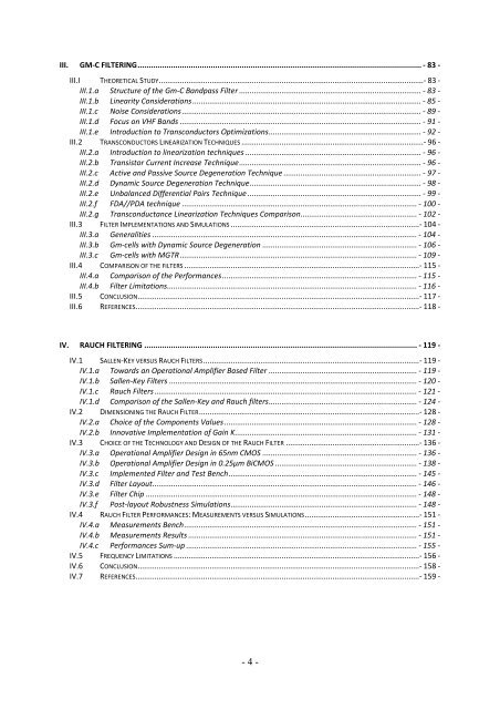
<strong>III</strong>. GM-C FILTERING................................................................................................................................ - 83 -<br />
<strong>III</strong>.I THEORETICAL STUDY.............................................................................................................................- 83 -<br />
<strong>III</strong>.1.a Structure of the <strong>Gm</strong>-C Bandpass Filter ...................................................................................... - 83 -<br />
<strong>III</strong>.1.b Linearity Consi<strong>de</strong>rations ............................................................................................................ - 85 -<br />
<strong>III</strong>.1.c Noise Consi<strong>de</strong>rations................................................................................................................. - 89 -<br />
<strong>III</strong>.1.d Focus on VHF Bands .................................................................................................................. - 91 -<br />
<strong>III</strong>.1.e Introduction to Transconductors Optimizations........................................................................ - 92 -<br />
<strong>III</strong>.2 TRANSCONDUCTORS LINEARIZATION TECHNIQUES ......................................................................................- 96 -<br />
<strong>III</strong>.2.a Introduction to linearization techniques ................................................................................... - 96 -<br />
<strong>III</strong>.2.b Transistor Current Increase Technique...................................................................................... - 96 -<br />
<strong>III</strong>.2.c Active and Passive Source Degeneration Technique ................................................................. - 97 -<br />
<strong>III</strong>.2.d Dynamic Source Degeneration Technique................................................................................. - 98 -<br />
<strong>III</strong>.2.e Unbalanced Differential Pairs Technique .................................................................................. - 99 -<br />
<strong>III</strong>.2.f FDA//PDA technique ............................................................................................................... - 100 -<br />
<strong>III</strong>.2.g Transconductance Linearization Techniques Comparison....................................................... - 102 -<br />
<strong>III</strong>.3 FILTER IMPLEMENTATIONS AND SIMULATIONS .........................................................................................- 104 -<br />
<strong>III</strong>.3.a Generalities ............................................................................................................................. - 104 -<br />
<strong>III</strong>.3.b <strong>Gm</strong>-cells with Dynamic Source Degeneration ......................................................................... - 106 -<br />
<strong>III</strong>.3.c <strong>Gm</strong>-cells with MGTR................................................................................................................ - 109 -<br />
<strong>III</strong>.4 COMPARISON OF THE FILTERS ...............................................................................................................- 115 -<br />
<strong>III</strong>.4.a Comparison of the Performances............................................................................................ - 115 -<br />
<strong>III</strong>.4.b Filter Limitations...................................................................................................................... - 116 -<br />
<strong>III</strong>.5 CONCLUSION.....................................................................................................................................- 117 -<br />
<strong>III</strong>.6 REFERENCES......................................................................................................................................- 118 -<br />
IV. RAUCH FILTERING ........................................................................................................................... - 119 -<br />
IV.1 SALLEN-KEY VERSUS RAUCH FILTERS......................................................................................................- 119 -<br />
IV.1.a Towards an Operational Amplifier Based Filter ...................................................................... - 119 -<br />
IV.1.b Sallen-Key Filters ..................................................................................................................... - 120 -<br />
IV.1.c Rauch Filters ............................................................................................................................ - 121 -<br />
IV.1.d Comparison of the Sallen-Key and Rauch filters...................................................................... - 124 -<br />
IV.2 DIMENSIONING THE RAUCH FILTER........................................................................................................- 128 -<br />
IV.2.a Choice of the Components Values ........................................................................................... - 128 -<br />
IV.2.b Innovative Implementation of Gain K...................................................................................... - 131 -<br />
IV.3 CHOICE OF THE TECHNOLOGY AND DESIGN OF THE RAUCH FILTER ...............................................................- 136 -<br />
IV.3.a Operational Amplifier Design in 65nm CMOS ......................................................................... - 136 -<br />
IV.3.b Operational Amplifier Design in 0.25µm BiCMOS ................................................................... - 138 -<br />
IV.3.c Implemented Filter and Test Bench......................................................................................... - 145 -<br />
IV.3.d Filter Layout............................................................................................................................. - 146 -<br />
IV.3.e Filter Chip ................................................................................................................................ - 148 -<br />
IV.3.f Post-layout Robustness Simulations........................................................................................ - 148 -<br />
IV.4 RAUCH FILTER PERFORMANCES: MEASUREMENTS VERSUS SIMULATIONS......................................................- 151 -<br />
IV.4.a Measurements Bench.............................................................................................................. - 151 -<br />
IV.4.b Measurements Results ............................................................................................................ - 151 -<br />
IV.4.c Performances Sum-up ............................................................................................................. - 155 -<br />
IV.5 FREQUENCY LIMITATIONS ....................................................................................................................- 156 -<br />
IV.6 CONCLUSION.....................................................................................................................................- 158 -<br />
IV.7 REFERENCES......................................................................................................................................- 159 -<br />
- 4 -


