

III. Gm-C Filtering - Epublications - Université de Limoges
III. Gm-C Filtering - Epublications - Université de Limoges
III. Gm-C Filtering - Epublications - Université de Limoges

You also want an ePaper? Increase the reach of your titles
YUMPU automatically turns print PDFs into web optimized ePapers that Google loves.
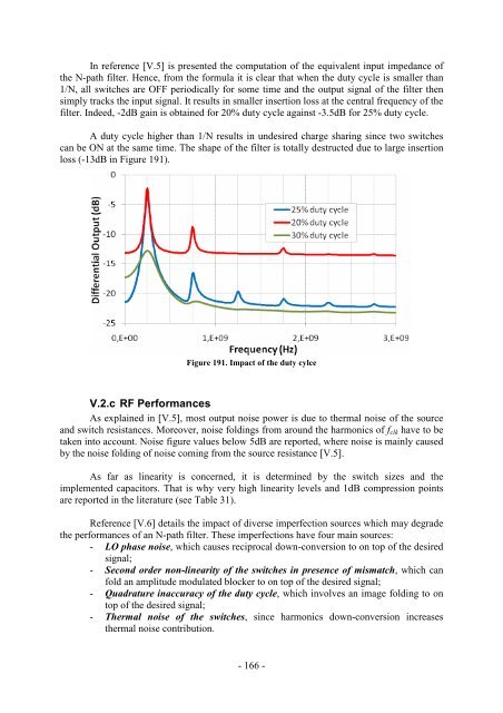
In reference [V.5] is presented the computation of the equivalent input impedance of<br />
the N-path filter. Hence, from the formula it is clear that when the duty cycle is smaller than<br />
1/N, all switches are OFF periodically for some time and the output signal of the filter then<br />
simply tracks the input signal. It results in smaller insertion loss at the central frequency of the<br />
filter. In<strong>de</strong>ed, -2dB gain is obtained for 20% duty cycle against -3.5dB for 25% duty cycle.<br />
A duty cycle higher than 1/N results in un<strong>de</strong>sired charge sharing since two switches<br />
can be ON at the same time. The shape of the filter is totally <strong>de</strong>structed due to large insertion<br />
loss (-13dB in Figure 191).<br />
Figure 191. Impact of the duty cylce<br />
V.2.c RF Performances<br />
As explained in [V.5], most output noise power is due to thermal noise of the source<br />
and switch resistances. Moreover, noise foldings from around the harmonics of fclk have to be<br />
taken into account. Noise figure values below 5dB are reported, where noise is mainly caused<br />
by the noise folding of noise coming from the source resistance [V.5].<br />
As far as linearity is concerned, it is <strong>de</strong>termined by the switch sizes and the<br />
implemented capacitors. That is why very high linearity levels and 1dB compression points<br />
are reported in the literature (see Table 31).<br />
Reference [V.6] <strong>de</strong>tails the impact of diverse imperfection sources which may <strong>de</strong>gra<strong>de</strong><br />
the performances of an N-path filter. These imperfections have four main sources:<br />
- LO phase noise, which causes reciprocal down-conversion to on top of the <strong>de</strong>sired<br />
signal;<br />
- Second or<strong>de</strong>r non-linearity of the switches in presence of mismatch, which can<br />
fold an amplitu<strong>de</strong> modulated blocker to on top of the <strong>de</strong>sired signal;<br />
- Quadrature inaccuracy of the duty cycle, which involves an image folding to on<br />
top of the <strong>de</strong>sired signal;<br />
- Thermal noise of the switches, since harmonics down-conversion increases<br />
thermal noise contribution.<br />
- 166 -


