

III. Gm-C Filtering - Epublications - Université de Limoges
III. Gm-C Filtering - Epublications - Université de Limoges
III. Gm-C Filtering - Epublications - Université de Limoges

You also want an ePaper? Increase the reach of your titles
YUMPU automatically turns print PDFs into web optimized ePapers that Google loves.
V. A Perspective for Future Developments<br />
V.1 N-path <strong>Filtering</strong> Principle<br />
N-path filtering is a method, already <strong>de</strong>scribed in the sixties and in the eighties [V.1<br />
and V.2], which uses the lack of reverse isolation of passive mixers to perform impedance<br />
transforms. A revival of interest for this technique occurs in 2010-2011 and exhibits<br />
promising results for the full integration of RF filtering.<br />
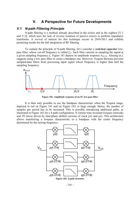
To explain the principle of N-path filtering, let’s consi<strong>de</strong>r a switched capacitor lowpass<br />
filter, whose cut-off frequency is called fLP. Such filter consists in sampling the signal at<br />
a given sampling frequency fc. Figure 181 <strong>de</strong>picts its amplitu<strong>de</strong> response ASCLP. Aliasing at fc<br />
suggests using a low pass filter to create a bandpass one. However, Nyquist theorem prevents<br />
sampled-data filters from processing input signal whose frequency is higher than half the<br />
sampling frequency.<br />
Figure 181. Amplitu<strong>de</strong> response of an SC low-pass filter<br />
It is then only possible to use the bandpass characteristic when the Nyquist range,<br />
<strong>de</strong>picted in red on Figure 181 and on Figure 183, is large enough. Hence, the number of<br />
samples per period has to be increased. This is possible introducing additional paths, as<br />
illustrated in Figure 182 for a 4-path configuration. N similar time invariant lowpass networks<br />
and 2N mixer driven by time/phase shifted versions of clock p(t) and q(t). This architecture<br />
allows transferring a lowpass characteristic to a bandpass with the center frequency<br />
<strong>de</strong>termined by the mixing frequency.<br />
Vin<br />
p(t) q(t)<br />
p(t-T/4) q(t-T/4)<br />
p(t-2T/4) q(t-2T/4)<br />
p(t-3T/4) q(t-3T/4)<br />
Figure 182. 4-path structure<br />
- 161 -<br />
Vout


