

III. Gm-C Filtering - Epublications - Université de Limoges
III. Gm-C Filtering - Epublications - Université de Limoges
III. Gm-C Filtering - Epublications - Université de Limoges

You also want an ePaper? Increase the reach of your titles
YUMPU automatically turns print PDFs into web optimized ePapers that Google loves.
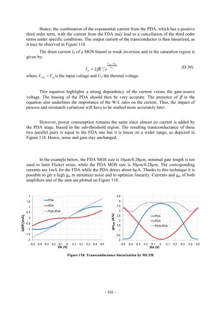
Hence, the combination of the exponential current from the PDA, which has a positive<br />
third or<strong>de</strong>r term, with the current from the FDA may lead to a cancellation of the third or<strong>de</strong>r<br />
terms un<strong>de</strong>r specific conditions. The output current of the transconductor is then linearized, as<br />
it may be observed in Figure 118.<br />
The drain current Id of a MOS biased in weak inversion and in the saturation region is<br />
given by:<br />
d<br />
≈ 2β U<br />
where VGS − Vth<br />
is the input voltage and UT the thermal voltage.<br />
I<br />
2<br />
T<br />
e<br />
V<br />
GS<br />
U<br />
−V<br />
T<br />
th<br />
- 101 -<br />
(D.39)<br />
This equation highlights a strong <strong>de</strong>pen<strong>de</strong>ncy of the current versus the gate-source<br />
voltage. The biasing of the PDA should then be very accurate. The presence of β in the<br />
equation also un<strong>de</strong>rlines the importance of the W/L ratio on the current. Thus, the impact of<br />
process and mismatch variations will have to be studied more accurately later.<br />
However, power consumption remains the same since almost no current is ad<strong>de</strong>d by<br />
the PDA stage, biased in the sub-threshold region. The resulting transconductance of these<br />
two parallel pairs is equal to the FDA one but it is linear on a wi<strong>de</strong>r range, as <strong>de</strong>picted in<br />
Figure 118. Hence, noise and gain stay unchanged.<br />
In the example below, the FDA MOS size is 16µm/0.28µm, minimal gate length is not<br />
used to limit Flicker noise, while the PDA MOS size is 50µm/0.28µm. The corresponding<br />
currents are 1mA for the FDA while the PDA draws about 6µA. Thanks to this technique it is<br />
possible to get a high gm to minimize noise and to optimize linearity. Currents and gm of both<br />
amplifiers and of the sum are plotted on Figure 118.<br />
Figure 118. Transconductance linearization by MGTR


