Aerodynamic Modeling and System Identification from Flight Data ...
Aerodynamic Modeling and System Identification from Flight Data ...
Aerodynamic Modeling and System Identification from Flight Data ...

You also want an ePaper? Increase the reach of your titles
YUMPU automatically turns print PDFs into web optimized ePapers that Google loves.
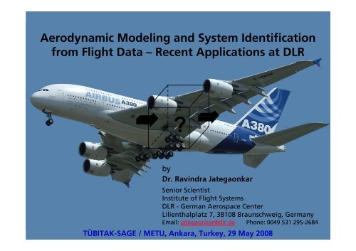
<strong>Aerodynamic</strong> <strong>Modeling</strong> <strong>and</strong> <strong>System</strong> <strong>Identification</strong><br />
<strong>from</strong> <strong>Flight</strong> <strong>Data</strong> – Recent Applications at DLR<br />
?<br />
by<br />
Dr. Ravindra Jategaonkar<br />
Senior Scientist<br />
Institute of <strong>Flight</strong> <strong>System</strong>s<br />
DLR - German Aerospace Center<br />
Lilienthalplatz 7, 38108 Braunschweig, Germany<br />
Email: jategaonkar@dlr.de Phone: 0049 531 295-2684<br />
TÜBITAK-SAGE / METU, Ankara, Turkey, 29 May 2008<br />
Dr. Ravindra Jategaonkar RTO Mission at Tübitak-SAGE, Ankara, Turkey, 26-29 May 2008 pp. 1
Contents<br />
Introduction<br />
Overview: Why <strong>and</strong> what is system identification<br />
Unified approach<br />
Quad-M basics (Maneuvers, Measurements, Methods, Models)<br />
Estimation methods<br />
Examples of <strong>Aerodynamic</strong> <strong>Modeling</strong><br />
- C-160 <strong>Aerodynamic</strong> <strong>Data</strong> Base:<br />
<strong>Data</strong> consistency checking<br />
Nonlinear control surface effectiveness<br />
Separation of pitch damping derivatives<br />
Stall hysteresis<br />
<strong>Modeling</strong> of l<strong>and</strong>ing gear effects<br />
- <strong>Data</strong>base validation<br />
- Wake Vortex Aircraft Encounter Model<br />
- EC-135 Helicopter<br />
6 DOF <strong>and</strong> extended models <strong>and</strong> Rotor wake modeling<br />
- Phoenix: Reusable orbiter glider,<br />
- UAV: Automatic Envelope Expansion through Adaptive <strong>Flight</strong> Control<br />
Concluding remarks<br />
Dr. Ravindra Jategaonkar RTO Mission at Tübitak-SAGE, Ankara, Turkey, 26-29 May 2008 pp. 2
Aircraft mass<br />
characteristics<br />
What is <strong>System</strong> <strong>Identification</strong>? (1)<br />
u z<br />
Dynamic <strong>System</strong><br />
Process noise<br />
(turbulence)<br />
State Equations x<br />
Measurement Eq.<br />
Inputs x &(<br />
t)<br />
= f ( x(<br />
t),<br />
u(<br />
t),<br />
ϕ)<br />
States y(<br />
t)<br />
= g(<br />
x(<br />
t),<br />
u(<br />
t),<br />
Θ)<br />
<strong>Aerodynamic</strong>s<br />
(unknown<br />
parameters)<br />
Sensor<br />
locations<br />
Measurement<br />
noise<br />
Outputs<br />
Sensor model<br />
(calibration factors,<br />
bias errors)<br />
AIM: To determine unknown model parameters Θ such that the model<br />
response y matches well with the measured system response z.<br />
Dr. Ravindra Jategaonkar RTO Mission at Tübitak-SAGE, Ankara, Turkey, 26-29 May 2008 pp. 3<br />
y
What is <strong>System</strong> <strong>Identification</strong>? (2)<br />
Inputs Outputs<br />
State<br />
.<br />
Equations<br />
u x = f (x, u, θ) x<br />
Simulation: given u <strong>and</strong> f, find x<br />
Control: given x <strong>and</strong> f, find u<br />
<strong>Identification</strong>: given u <strong>and</strong> x, find f<br />
?<br />
SysID: an Inverse Problem<br />
Given the answer, what are the questions,<br />
i.e., look at the results <strong>and</strong> try to figure<br />
out what situation caused those results.<br />
Classification<br />
Parameter<br />
estimation <strong>System</strong><br />
identification<br />
Simulation<br />
(1) <strong>System</strong> <strong>Identification</strong><br />
Concerned with the mathematical<br />
structure of a flight vehicle model<br />
(2) Parameter Estimation<br />
Quantifying of parameters for a<br />
selected flight vehicle model<br />
Is the commonly used terminology<br />
PID appropriate?<br />
Dr. Ravindra Jategaonkar RTO Mission at Tübitak-SAGE, Ankara, Turkey, 26-29 May 2008 pp. 4
Why <strong>System</strong> <strong>Identification</strong>?<br />
Need <strong>and</strong> quest to better underst<strong>and</strong> the system<br />
- Cause-effect relationship purported to underlie the physical phenomenon<br />
Mathematical models required for:<br />
- Investigation of system performance <strong>and</strong> characteristics<br />
- <strong>Aerodynamic</strong> databases valid over operational envelope for flight simulators<br />
- High-fidelity / high-b<strong>and</strong>width models for in-flight simulators<br />
- <strong>Flight</strong> control law design<br />
- Analysis of h<strong>and</strong>ling qualities compliance<br />
<strong>Aerodynamic</strong> databases <strong>from</strong> flight data<br />
- Analytical estimates: validity <strong>and</strong> inadequate theory !<br />
- Wind-tunnel predictions: model scaling, Reynold's number,<br />
dynamic derivatives, cross coupling, aero-servo-elastic effects !!<br />
Dr. Ravindra Jategaonkar RTO Mission at Tübitak-SAGE, Ankara, Turkey, 26-29 May 2008 pp. 5
Classical Approach<br />
1919 - mid 1960's<br />
Classical<br />
Methods<br />
- Deterministic<br />
-Graphical<br />
(Paper & Pencil)<br />
- Frequency domain<br />
- Analog computation<br />
Transition Phase<br />
Late 1960's<br />
Dinosauric<br />
Digital<br />
Computation<br />
Modern Era<br />
1966 - 2008<br />
Advanced<br />
Methods<br />
- Statistical analysis<br />
- Time domain<br />
- Frequency domain<br />
- Digital computation<br />
Dr. Ravindra Jategaonkar RTO Mission at Tübitak-SAGE, Ankara, Turkey, 26-29 May 2008 pp. 6
Unified Approach to<br />
<strong>Flight</strong> Vehicle <strong>System</strong> <strong>Identification</strong><br />
Maneuver<br />
Optimized<br />
Input<br />
A Priori Values,<br />
lower/upper<br />
bounds<br />
Model<br />
Structure<br />
Input<br />
Complementary<br />
<strong>Flight</strong> <strong>Data</strong><br />
Quad-M Basics<br />
<strong>Flight</strong> Vehicle<br />
M<br />
Estimation<br />
Algorithm /<br />
Optimization<br />
Actual<br />
Response<br />
Parameter<br />
odels Adjustments<br />
Mathematical<br />
Model /<br />
Simulation<br />
M<br />
ethods<br />
Model<br />
Validation<br />
Measurements<br />
<strong>Data</strong> Collection<br />
& Compatibility<br />
Parameter Estimation<br />
<strong>Identification</strong><br />
Criteria<br />
Response<br />
Error<br />
Model Response<br />
<strong>Identification</strong> Phase<br />
Validation Phase<br />
Dr. Ravindra Jategaonkar RTO Mission at Tübitak-SAGE, Ankara, Turkey, 26-29 May 2008 pp. 7<br />
+<br />
-
Aircraft Parameter Estimation Methods<br />
Types <strong>and</strong> Classification<br />
Stable <strong>System</strong>s<br />
Regression Analysis<br />
- Linear modeling<br />
- <strong>Data</strong> compatibility required<br />
- <strong>Data</strong> partitioning<br />
Output Error Method<br />
- Accounts for measurement noise<br />
- Time <strong>and</strong> frequency domain<br />
Filter Error Method<br />
Accounts for both process noise<br />
(turbulence) <strong>and</strong> measurement noise<br />
Most general <strong>and</strong> most complex<br />
Neural Networks<br />
- Recurrent neural network<br />
- Feed forward neural network<br />
- Local model network<br />
Pilot<br />
inputs<br />
<strong>Flight</strong><br />
Control<br />
Unstable <strong>System</strong>s<br />
Surface<br />
Deflections<br />
Methods:<br />
- Regression Analysis<br />
- Filter Error Method<br />
- Extended Kalman Filter<br />
- Output Error Method with<br />
artificial stabilization<br />
Unstable<br />
Aircraft<br />
Motion<br />
Difficulties:<br />
- Open loop plant identification: basic aircraft<br />
is unstable (due to the aerodynamic design)<br />
- States <strong>and</strong> controls are highly correlated<br />
(due to the design of flight control laws)<br />
- Aircraft may be excited by process noise<br />
(e.g., induced by forebody vortices)<br />
Dr. Ravindra Jategaonkar RTO Mission at Tübitak-SAGE, Ankara, Turkey, 26-29 May 2008 pp. 8
C nβ<br />
C nβ<br />
0.22<br />
0.20<br />
0.18<br />
0.16<br />
0.22<br />
0.20<br />
0.18<br />
Parameter Estimation Accounting for<br />
Atmospheric Turbulence<br />
Weathercock stability (yaw stiffness) Rudder effectiveness<br />
<strong>Flight</strong><br />
No.<br />
209<br />
112<br />
214<br />
219<br />
221<br />
216<br />
222<br />
223<br />
Output Error Method<br />
Filter Error Method<br />
0.16 -3 3 9<br />
Angle of Attack, deg<br />
flight in in<br />
turbulence<br />
15<br />
Output Error Method<br />
-0.36<br />
0.15 0.25 0.35<br />
Mach Number<br />
0.45 0.55<br />
Dr. Ravindra Jategaonkar RTO Mission at Tübitak-SAGE, Ankara, Turkey, 26-29 May 2008 pp. 9<br />
C nζ<br />
C nζ<br />
-0.18<br />
-0.24<br />
-0.30<br />
-0.36<br />
-0.18<br />
-0.24<br />
-0.30<br />
Filter Error Method
A340-600, 2001<br />
EC-135, 2001<br />
N250-PA1, 1999<br />
A318-121, 2002<br />
Dornier 328, 1995-96<br />
X-31A, 1992-94<br />
A Retrospective<br />
Application Spectrum:<br />
<strong>Flight</strong> Vehicles<br />
Software Tools:<br />
ESTIMA<br />
FITLAB<br />
Dyn. Simulation in WT,1982<br />
Beaver DHC-2, 1983<br />
XV-15, 1990-91<br />
Transall C-160, 1992-93<br />
HFB-320, 1985<br />
ATTAS, 1989-90<br />
Dr. Ravindra Jategaonkar RTO Mission at Tübitak-SAGE, Ankara, Turkey, 26-29 May 2008 pp. 10
High speed<br />
regime<br />
Stall approach<br />
<strong>and</strong> stall<br />
Single<br />
engine<br />
Take-off<br />
l<strong>and</strong>ing<br />
General Concept of <strong>Aerodynamic</strong><br />
Model <strong>Identification</strong><br />
Ground<br />
h<strong>and</strong>ling<br />
Normal <strong>Flight</strong><br />
regime<br />
Engine<br />
L<strong>and</strong>ing<br />
gear<br />
Ramp door<br />
Airdrop<br />
Ground<br />
effect<br />
Dr. Ravindra Jategaonkar RTO Mission at Tübitak-SAGE, Ankara, Turkey, 26-29 May 2008 pp. 11
Altitude<br />
FL 300<br />
FL 260<br />
FL 160<br />
FL 80<br />
FL 20<br />
Elevator 3-2-1-1<br />
Short Period<br />
Typical <strong>Flight</strong> Test Program for<br />
<strong>System</strong> <strong>Identification</strong><br />
Test Case: C-160 Transall<br />
0.2 0.3 0.4 0.5 Mach No.<br />
80 KCAS<br />
100 KCAS<br />
120 KCAS<br />
160 KCAS<br />
100 150 200 250 300 True Airspeed (Kts)<br />
Elevator pulse<br />
Phugoid<br />
140 KCAS<br />
Bank angle<br />
Level Turn Maneuver<br />
Dr. Ravindra Jategaonkar RTO Mission at Tübitak-SAGE, Ankara, Turkey, 26-29 May 2008 pp. 12<br />
195 KCAS<br />
Aileron/Spoiler<br />
Bank to Bank<br />
Maneuver<br />
230 KCAS<br />
Rudder Doublet<br />
Dutch Roll<br />
277 KCAS<br />
Thrust Doublet
Kinematic Consistency Checking of<br />
Recorded <strong>Data</strong><br />
General Approach, sensor model <strong>and</strong> estimation algorithm<br />
-To ensure that the measurements are<br />
consistent <strong>and</strong> error free.<br />
- Inertial measurements (accelerations <strong>and</strong><br />
angular rates are highly accurate.<br />
- Kinematic equations with no uncertainties;<br />
Accurate information about aircraft state;<br />
- Means to calibrate parameters with lower<br />
accuracy (angle of attack & sideslip).<br />
Kinematic Equations<br />
Linear Accelerations<br />
Velocity components<br />
Rotational rates<br />
∫<br />
(u, v, w)<br />
ax, ay, az, p, q, r Attitude angles<br />
Initial conditions: u 0, v 0, w 0, p 0, q 0, r 0<br />
Scale factors: K p, K q, K r<br />
Bias: Δa x, Δa y, Δa z, Δp, Δq, Δr<br />
Sensor calibration model<br />
Scale factor <strong>and</strong> bias<br />
Time delay<br />
p<br />
dα<br />
m<br />
= Kα<br />
p<br />
dyn<br />
α<br />
nb<br />
+ Δ p<br />
dα<br />
p<br />
dβ<br />
m<br />
= K<br />
β<br />
p<br />
dyn<br />
β<br />
nb<br />
+ Δ p<br />
dβ<br />
α α τ α τα<br />
Δ<br />
dα<br />
p ) t (<br />
p<br />
d m<br />
( t ) = K p<br />
dyn<br />
( t − q )<br />
nb<br />
− +<br />
Parameter estimation<br />
- Output error method for nonlinear systems<br />
- Bounded-Variable Gauss-Newton algorithm<br />
- Multiple experiment evaluation<br />
Kα , Δ p<br />
dα<br />
, Kβ<br />
, Δ p<br />
dβ<br />
, τα<br />
, τ<br />
β , τ<br />
q<br />
Dr. Ravindra Jategaonkar RTO Mission at Tübitak-SAGE, Ankara, Turkey, 26-29 May 2008 pp. 13
Noseboom Mounted 5 Hole Probe<br />
<strong>Flight</strong> Validation ATTAS VFW-614<br />
K<br />
0.08<br />
0.06<br />
0.04<br />
0.02<br />
0 0.4 0.6 1.0 2.0<br />
Mach number<br />
<strong>Flight</strong> estimates Kα<br />
Calibration factors independent of configuration<br />
0.063<br />
0<br />
<strong>Flight</strong> Validation C-160<br />
20 40<br />
Flap<br />
deg 60<br />
Calibration factors configuration dependent<br />
Dr. Ravindra Jategaonkar RTO Mission at Tübitak-SAGE, Ankara, Turkey, 26-29 May 2008 pp. 14<br />
Scale<br />
factor<br />
0.084<br />
0.077<br />
0.070<br />
ATTAS<br />
Kα<br />
K β
C-160: High-Fidelity Simulator <strong>Data</strong> Base<br />
<strong>Aerodynamic</strong> data base valid over<br />
the entire operational envelope<br />
- Nonlinear aerodynamics<br />
- Interference <strong>and</strong> coupling effects<br />
<strong>Identification</strong> of C-160 specific<br />
operational characteristics<br />
- Ramp door interference,<br />
- air drop, etc.<br />
<strong>Identification</strong> of dynamic stall<br />
- Unsteady flow separation<br />
<strong>Identification</strong> of<br />
- Ground effect<br />
- L<strong>and</strong>ing <strong>and</strong> Take-off<br />
- Failure states<br />
Validation of flight estimated database<br />
- FAA Level-D<br />
<strong>Flight</strong> estimate of dihedral effect<br />
Point ID: Single trim points<br />
Multi-Point ID: Several trim conditions<br />
Dr. Ravindra Jategaonkar RTO Mission at Tübitak-SAGE, Ankara, Turkey, 26-29 May 2008 pp. 15<br />
-0.12<br />
C lβ<br />
-0.18<br />
η = 40°<br />
K<br />
η = 30°<br />
K<br />
L<strong>and</strong>ing<br />
Flap<br />
Point <strong>Identification</strong><br />
Multi-point <strong>Identification</strong><br />
-0.24<br />
η = 20°<br />
K η = 0° K<br />
-6 0 6 deg 12<br />
Angle of Attack
elevator<br />
deflection<br />
<strong>Identification</strong> of Elevator Control Effectiveness<br />
Test Case: Transall C-160<br />
2<br />
deg<br />
-18<br />
0 10 20 s 30<br />
time<br />
-6<br />
m/s2<br />
Vertical<br />
acceleration<br />
pitchrate<br />
angle of<br />
attack<br />
-12<br />
8<br />
deg/s<br />
0<br />
-8<br />
18<br />
deg<br />
6<br />
Linear model<br />
Accounting for nonlinearity<br />
Dr. Ravindra Jategaonkar RTO Mission at Tübitak-SAGE, Ankara, Turkey, 26-29 May 2008 pp. 16<br />
-6<br />
m/s2<br />
Vertical<br />
acceleration<br />
pitch rate<br />
angle of<br />
attack<br />
-12<br />
8<br />
deg/s<br />
0<br />
18<br />
deg<br />
6<br />
Effectiveness<br />
Deflection
<strong>Aerodynamic</strong> <strong>Modeling</strong>: Complex Models<br />
Linear models (e.g. Rolling moment coefficient)<br />
C<br />
l<br />
= C + C<br />
l0<br />
l<br />
β<br />
β + C<br />
l<br />
p<br />
+ C r + C<br />
l r l<br />
Nonlinear models (e.g. Tail lift coefficient)<br />
Unsteady aerodynamics (e.g. Stall hysteresis)<br />
p<br />
ξ<br />
ξ + C ζ<br />
lζ<br />
Lη 2 α 2 α T CLη 3 η 2<br />
T L Lη α C = C α + C η + C T + C + η<br />
L T<br />
L T α<br />
α<br />
Unsteady <strong>Aerodynamic</strong> Model<br />
Lift coefficient<br />
C L (α, x) = C Lα<br />
Flow Separation Point<br />
x<br />
1 + x<br />
Dr. Ravindra Jategaonkar RTO Mission at Tübitak-SAGE, Ankara, Turkey, 26-29 May 2008 pp. 17<br />
α<br />
x = 0<br />
CL( α,<br />
x)<br />
x = 1<br />
2<br />
2<br />
α
α<br />
a Z<br />
θ<br />
V<br />
δ e<br />
25<br />
deg<br />
-10<br />
0.0<br />
g<br />
-1.2<br />
20<br />
deg<br />
-40<br />
140<br />
kt<br />
80<br />
20<br />
deg<br />
Time Responses<br />
-30<br />
0 20 40<br />
Time, sec<br />
Unsteady <strong>Aerodynamic</strong>s<br />
60<br />
Lift Coefficient<br />
0.0<br />
-8 0 8 16 24<br />
Angle of Attack α , deg<br />
Dr. Ravindra Jategaonkar RTO Mission at Tübitak-SAGE, Ankara, Turkey, 26-29 May 2008 pp. 18<br />
C L<br />
3.0<br />
2.0<br />
1.0<br />
DO 328<br />
<strong>Flight</strong> measured<br />
Model identified
<strong>Modeling</strong> of L<strong>and</strong>ing Gear Effects (1)<br />
<strong>Modeling</strong> <strong>and</strong> Experimental Aspects<br />
Important for simulation of<br />
take-offs <strong>and</strong> l<strong>and</strong>ings<br />
Longitudinal <strong>and</strong> lateral-directional<br />
maneuvers with gear down<br />
8000 ft <strong>and</strong> 16000 ft<br />
120, 140 <strong>and</strong> 160 kts<br />
Test Case: Transall C-160<br />
Basic aerodynamic model:<br />
Discernible deviations in<br />
- longitudinal motion<br />
- lateral-directional motion variables<br />
Neglecting L<strong>and</strong>ing Gear Effects<br />
Dr. Ravindra Jategaonkar RTO Mission at Tübitak-SAGE, Ankara, Turkey, 26-29 May 2008 pp. 19<br />
a<br />
r<br />
θ<br />
α<br />
β<br />
x<br />
m/s 2<br />
1.2<br />
.0<br />
10<br />
deg/s<br />
0<br />
-8<br />
13<br />
deg<br />
0<br />
-7<br />
5<br />
deg<br />
0<br />
8<br />
deg<br />
0<br />
-8<br />
0 20 40 s<br />
60<br />
Time<br />
<strong>Flight</strong> measurement (C-160 Transall)<br />
Model identification
<strong>Modeling</strong> of L<strong>and</strong>ing Gear Effects (2)<br />
<strong>Modeling</strong> of <strong>Aerodynamic</strong> Effects due to LG<br />
Incremental aerodynamic modeling<br />
Longitudinal motion:<br />
Lift, drag <strong>and</strong> pitching moment coeff.<br />
ΔC LLG , ΔC DLG , ΔC mLG<br />
Lateral-Directional motion:<br />
- Increased weathercock stability ΔC nβLG<br />
- Sideforce due to sideslip ΔC YβLG<br />
Test Case: Transall C-160<br />
Accounting for L<strong>and</strong>ing Gear Effects<br />
-8<br />
0 20 Time 40 s 60<br />
<strong>Flight</strong> measurement (C-160 Transall)<br />
Model identification<br />
Dr. Ravindra Jategaonkar RTO Mission at Tübitak-SAGE, Ankara, Turkey, 26-29 May 2008 pp. 20<br />
a<br />
r<br />
θ<br />
α<br />
β<br />
x<br />
1.2<br />
m/s 2<br />
.0<br />
10<br />
deg/s<br />
0<br />
-8<br />
13<br />
deg<br />
0<br />
-7<br />
5<br />
deg<br />
0<br />
8<br />
deg<br />
0
Verticalacceleration<br />
Pitch<br />
rate<br />
Pitch<br />
attitude<br />
Pitch<br />
acceleration<br />
CGlocation<br />
-8<br />
m/s 2<br />
-13<br />
-13<br />
5<br />
5<br />
deg/s deg/s<br />
-5<br />
8<br />
deg<br />
2<br />
deg/s<br />
-2<br />
8<br />
20<br />
Measurement<br />
Simulation<br />
C-160: Load Drop (4.6 t)<br />
Neglecing Variations in Aircraft Mass<br />
Characteristics<br />
Dr. Ravindra Jategaonkar RTO Mission at Tübitak-SAGE, Ankara, Turkey, 26-29 May 2008 pp. 21<br />
-8<br />
m/s 2<br />
-5<br />
6<br />
deg<br />
2<br />
deg/s<br />
-16<br />
-16<br />
50<br />
50<br />
% %<br />
0 5 10 15<br />
Time (sec)<br />
2<br />
8<br />
20<br />
Accounting for Variations in the<br />
Aircraft Mass Characteristics<br />
0 5 10<br />
Time (sec)<br />
15
How do you know that you got the<br />
right answer?<br />
1.<br />
2.<br />
3.<br />
4.<br />
5.<br />
St<strong>and</strong>ard derivations<br />
Correlation among the estimates<br />
Goodness of fit<br />
Plausibility of estimates<br />
(WT data base)<br />
Model predictive capability<br />
"ACID TEST"<br />
Simulation <strong>and</strong> comparison with<br />
flight data not used in identification<br />
<strong>Data</strong> Base Validation (1)<br />
-12<br />
10<br />
deg/sec<br />
-7<br />
0 2 Time, sec 4 6<br />
10<br />
dB<br />
0<br />
Magn.<br />
-10<br />
q model<br />
qmeasured<br />
model<br />
90<br />
deg<br />
0<br />
Phase<br />
q model<br />
qmeasured<br />
-90<br />
0.1 1.0<br />
10 100<br />
Frequency, rad/sec<br />
Dr. Ravindra Jategaonkar RTO Mission at Tübitak-SAGE, Ankara, Turkey, 26-29 May 2008 pp. 22<br />
q<br />
9<br />
deg<br />
δ e<br />
C-160 Pitch Response<br />
q model
C nβ<br />
0.3<br />
1/rad<br />
0.2<br />
Weathercock stability<br />
WT/analytical<br />
prediction<br />
flight estimates<br />
δ f = 30°<br />
δ f = 0°<br />
0.1<br />
-10 0<br />
angle of attack<br />
deg 15<br />
Tolerances:<br />
Frequency: +- 0.5 s or 10%<br />
Damping: +- 0.02<br />
<strong>Data</strong> Base Validation (2)<br />
yaw<br />
rate<br />
-8<br />
0 5 time 10 15 s 20<br />
Dr. Ravindra Jategaonkar RTO Mission at Tübitak-SAGE, Ankara, Turkey, 26-29 May 2008 pp. 23<br />
10<br />
deg/s<br />
0<br />
-10<br />
8<br />
deg<br />
angle<br />
0<br />
of<br />
sideslip<br />
-8<br />
8<br />
deg<br />
rudder<br />
0<br />
<strong>Flight</strong> measured<br />
Dutch roll dynamics<br />
WT database prediction<br />
SysID database prediction<br />
WT-Predictions: 4.18 s 0.207<br />
<strong>Flight</strong> estimated <strong>Data</strong>base: 5.04 s 0.202<br />
<strong>Flight</strong> recorded responses: 5.12 s 0.198
Do-328: St<strong>and</strong>-alone versus Integrated Models<br />
Aircraft<br />
Motion<br />
Variables<br />
Pilot Input<br />
Forces<br />
Pilot<br />
Input<br />
Forces<br />
<strong>Data</strong> Base Validation (3)<br />
Reversible<br />
<strong>Flight</strong> Control<br />
Dynamics<br />
Control<br />
Surface<br />
Deflect.<br />
<strong>Flight</strong> controls st<strong>and</strong>-alone<br />
Reversible<br />
<strong>Flight</strong> Control<br />
Dynamics<br />
Control<br />
Surface<br />
Deflect.<br />
Control<br />
Surface<br />
Deflect.<br />
Integrated model<br />
measured data simulated data<br />
Rigid Body<br />
Dynamics<br />
Rigid Body<br />
Dynamics<br />
Aircraft<br />
Motion<br />
Variables<br />
Rigid-body st<strong>and</strong>-alone<br />
Aircraft<br />
Motion<br />
Variables<br />
Dr. Ravindra Jategaonkar RTO Mission at Tübitak-SAGE, Ankara, Turkey, 26-29 May 2008 pp. 24
V<br />
h<br />
θ<br />
φ<br />
δ e<br />
<strong>Data</strong> Base Validation (4)<br />
DO-328:Normal L<strong>and</strong>ing<br />
130<br />
kt<br />
90<br />
250<br />
ft<br />
0<br />
10<br />
deg<br />
-5<br />
5<br />
deg<br />
-10<br />
20<br />
deg<br />
-10<br />
10<br />
deg<br />
δr Complete L<strong>and</strong>ing Phase<br />
3 kt<br />
10 ft<br />
1.5 deg<br />
2 deg<br />
-5<br />
0 10 Time (sec)<br />
20<br />
0<br />
8<br />
deg<br />
θ<br />
2<br />
5<br />
deg<br />
φ<br />
<strong>Flight</strong> measured (DO 328)<br />
Model identified<br />
FAA AC 120-40C tolerances<br />
Dr. Ravindra Jategaonkar RTO Mission at Tübitak-SAGE, Ankara, Turkey, 26-29 May 2008 pp. 25<br />
h<br />
δ e<br />
60<br />
ft<br />
-5<br />
0<br />
deg<br />
-10<br />
Exp<strong>and</strong>ed View (Touch down)<br />
10 ft<br />
1.5 deg<br />
2 deg<br />
14 16<br />
Time (sec)<br />
18
Validation Example 3:<br />
Critical Engine Failure (DO 328)<br />
Engine failure during the critical<br />
phase of takeoff<br />
Response to rudder <strong>and</strong><br />
aileron important<br />
Complete sequence as a single time<br />
segment (st<strong>and</strong>-still, acceleration,<br />
Rotation, <strong>and</strong> climb to 200 ft)<br />
No closed-loop controller<br />
Tolerances: 3 kt on airspeed<br />
20 ft on altitude<br />
1.5 deg on pitch attitude<br />
2.0 deg on bank<br />
<strong>Data</strong> Base Validation (5)<br />
<strong>Flight</strong> measured<br />
Model identified<br />
Dr. Ravindra Jategaonkar RTO Mission at Tübitak-SAGE, Ankara, Turkey, 26-29 May 2008 pp. 26<br />
V<br />
h<br />
θ<br />
φ<br />
δ e<br />
δ r<br />
150<br />
kt<br />
0<br />
-50<br />
300<br />
ft<br />
0<br />
-100<br />
15<br />
deg<br />
0<br />
-5<br />
10<br />
deg<br />
0<br />
-5<br />
30<br />
deg<br />
0<br />
-15<br />
10<br />
deg<br />
0<br />
-20<br />
4000<br />
daN<br />
FL , FR 0<br />
-2000<br />
left engine shut off<br />
0 10 20 30 s<br />
time
Wake Vortex Aircraft Encounter Model (1)<br />
Full Scale <strong>Flight</strong> tests: <strong>Data</strong> Gathering<br />
Wake vortex encounters:<br />
- Aircraft reaction dominantly affected<br />
- Critical situation during<br />
safety-critical flight phases<br />
(l<strong>and</strong>ing, vicinity of airport)<br />
Full scale flight tests with ATTAS<br />
followed by Do-128 or Cessna Citation<br />
Separation class medium<br />
wake<br />
generation<br />
100 encounters under steady atmospheric conditions.<br />
smoke trace<br />
0.5 nm<br />
Dr. Ravindra Jategaonkar RTO Mission at Tübitak-SAGE, Ankara, Turkey, 26-29 May 2008 pp. 27<br />
1 nm<br />
1.5 nm<br />
Reaction of follower Aircraft:<br />
- Up to 80° bank angle; typical 30-40°; Bump; Uncomfortable; usually does not<br />
lead to loss of control (banking motion is averaged out)<br />
- More important: lateral acceleration; may lead to injury to crew or Passenger
Wake Vortex Aircraft Encounter Model (2)<br />
Schematic of Two Step Procedure for Vortex Model <strong>Identification</strong><br />
measured<br />
flight test test<br />
data<br />
data<br />
pilot’s<br />
control<br />
inputs<br />
flow measurements<br />
accel.,<br />
rates, flight flight<br />
attitude, path path<br />
altitude, reconstruction<br />
reconstruction<br />
velocity (FPR) (FPR)<br />
basic basic<br />
A/C A/C aero aero<br />
model model<br />
aerodynamic<br />
interaction<br />
model model<br />
Vortex model<br />
forces,<br />
moments<br />
+ 6-DOF 6-DOF<br />
A/C<br />
+ A/C<br />
simulation<br />
Δ forces,<br />
Δ moments<br />
wake vortex<br />
characteristics<br />
accelerations, rates,<br />
attitude, altitude, velocity<br />
-<br />
outputs<br />
step 1:<br />
“Flow field<br />
characterization”<br />
step 2:<br />
“Encounter model<br />
validation”<br />
Dr. Ravindra Jategaonkar RTO Mission at Tübitak-SAGE, Ankara, Turkey, 26-29 May 2008 pp. 28<br />
+<br />
model<br />
accuracy
Wake Vortex Aircraft Encounter Model (3)<br />
Analytical Model<br />
The model consists of two idealized,<br />
superimposed counter-rotating single<br />
Vortices. Model parameters:<br />
- vortex circulation Γ,<br />
- core radius r C,<br />
- lateral vortex separation b V,<br />
- vortex location in space.<br />
The tangential velocity of one vortex<br />
as a function of the distance <strong>from</strong> the<br />
core, V t(r), is described in terms of the<br />
circulation Γ <strong>and</strong> the core radius r C:<br />
Lamb − Oseen :<br />
V<br />
t<br />
( r)<br />
=<br />
Γ<br />
2π<br />
r<br />
⎜<br />
⎛1− e<br />
⎝<br />
−1.<br />
2544r<br />
2 /<br />
r<br />
2<br />
c<br />
⎟<br />
⎞<br />
⎠<br />
Dr. Ravindra Jategaonkar RTO Mission at Tübitak-SAGE, Ankara, Turkey, 26-29 May 2008 pp. 29<br />
V t,max<br />
r C<br />
left<br />
vortex<br />
V<br />
t<br />
b v<br />
V t<br />
Burnham<br />
( r)<br />
=<br />
−<br />
r C<br />
right<br />
vortex<br />
Hallock<br />
Γ r<br />
2π<br />
r<br />
2<br />
r<br />
2<br />
c<br />
+<br />
:<br />
y
Wake Vortex Aircraft Encounter Model (4)<br />
Wake velocity components during lateral encounter<br />
horizontal velocity vertical velocity<br />
Noseboom<br />
Right wing<br />
Left wing<br />
15<br />
m/s<br />
-20<br />
10<br />
m/s<br />
-15<br />
10<br />
m/s<br />
-15<br />
0 2<br />
time<br />
4 S 6<br />
Dr. Ravindra Jategaonkar RTO Mission at Tübitak-SAGE, Ankara, Turkey, 26-29 May 2008 pp. 30<br />
10<br />
m/s<br />
-15<br />
6<br />
m/s<br />
-8<br />
6<br />
m/s<br />
-8<br />
0 2 4 S<br />
time<br />
6
Wake Vortex Aircraft Encounter Model (5)<br />
<strong>Flight</strong> estimated vortex model parameters<br />
Identified core radius r C<br />
<strong>and</strong> circulation Γ of the<br />
Burham-Hallock model<br />
for do-128 encounters<br />
<strong>from</strong> three flights.<br />
Conformance with Theory:<br />
- Expected decay of circulation<br />
- Increase of core radius<br />
- Initial core radius ~ 0.75 m,<br />
(roughly 3.5% of the wake<br />
Generating wing span which<br />
Is somewhat smaller than<br />
Commonly stated value of 5%)<br />
circulation, m 2 /s<br />
core radius, m<br />
200<br />
160<br />
80<br />
0<br />
3.0<br />
2.0<br />
1.0<br />
0.0<br />
<strong>Flight</strong> 1, 14.08.2001<br />
<strong>Flight</strong> 2, 15.08.2001<br />
<strong>Flight</strong> 3, 22.03.2002<br />
0 1 2 3 4 5<br />
normalized time t*=t/t 0<br />
Dr. Ravindra Jategaonkar RTO Mission at Tübitak-SAGE, Ankara, Turkey, 26-29 May 2008 pp. 31
EC-135 Flying Helicopter Simulator (1)<br />
Model Predictive Capability<br />
Forward speed 60 kts:<br />
Two flight maneuvers (Lateral <strong>and</strong><br />
pedal inputs)<br />
6-DOF Rigid-Body model:<br />
- Angle of attack dependent lateraldirectional<br />
derivatives<br />
- Nonlinear aerodynamics; Weathercock<br />
stability for +ve <strong>and</strong> -ve sideslip angles<br />
0 10 20<br />
time<br />
30 s 40<br />
Dr. Ravindra Jategaonkar RTO Mission at Tübitak-SAGE, Ankara, Turkey, 26-29 May 2008 pp. 32<br />
p<br />
q<br />
r<br />
0.3<br />
rad/s<br />
0<br />
-0.5<br />
0.3<br />
rad/s<br />
0<br />
-0.3<br />
0.3<br />
rad/s<br />
α<br />
β<br />
0<br />
-0.3<br />
0.2<br />
rad<br />
0<br />
-0.2<br />
0.3<br />
rad<br />
0<br />
-0.3<br />
75<br />
%<br />
δ lat,<br />
δ ped<br />
35
EC-135 Flying Helicopter Simulator (2)<br />
Rotor Wake <strong>Modeling</strong><br />
Roll <strong>and</strong> pitch in hover <strong>and</strong> at low speeds:<br />
unsymmetrical vortex compression <strong>and</strong><br />
dilatation act on the induced velocity field<br />
in the proximity of the main rotor.<br />
Effective AoA at the blade sections changed.<br />
<strong>Aerodynamic</strong> rotor loads directly affected.<br />
Rotor gyroscopic behavior due to the blade<br />
flapping dynamics forced by these loads<br />
leads to strong cross coupling effects of the<br />
helicopter due to the wake distortion.<br />
Current research topic:<br />
Suitable flight dynamic models describing<br />
this phenomenon to obtain improved<br />
simulation fidelity in off-axis response<br />
Pure Hover<br />
Pitching motion in Hover<br />
Dr. Ravindra Jategaonkar RTO Mission at Tübitak-SAGE, Ankara, Turkey, 26-29 May 2008 pp. 33
EC-135 Flying Helicopter Simulator (3)<br />
Dynamic Wake Model: Parametric extension of Pitt <strong>and</strong> Peters:<br />
⎡ ⎤<br />
⎢<br />
0<br />
−<br />
−1<br />
⎥<br />
λ + λ = + L ⎢K<br />
−β<br />
⎥<br />
Ω ⎢<br />
p<br />
( p<br />
s<br />
)<br />
⎥<br />
⎢K<br />
( q −β<br />
) ⎥<br />
⎣ q c ⎦<br />
ˆ<br />
1 1<br />
L c ˆ M &<br />
&<br />
&<br />
M: Apparent mass matrix associated with the<br />
acceleration terms <strong>from</strong> momentum theory<br />
L: gain matrix, λ (= [λ 0 , λ s , λ c ] T ) the inflow ratio<br />
describing the first harmonic terms<br />
c (= [c T , c 1 , c m ] T ): rotor load coefficients wrt rotor<br />
thrust <strong>and</strong> aerodynamic pitch <strong>and</strong> roll moment,<br />
Ω: main rotor rotation speed<br />
K p <strong>and</strong> K q: Wake distortion parameters for<br />
longitudinal <strong>and</strong> lateral distribution of the<br />
induced velocity.<br />
Last term on RHS: Parametric term that feeds<br />
back the roll <strong>and</strong> pitch rates of the rotor tip<br />
path plane wrt to the surrounding air to the<br />
induced velocity distribution over the rotor disk<br />
Estimate Kp <strong>and</strong> Kq Theoretical estimates of<br />
Wake distortion parameters<br />
From flight tests applying<br />
SysId methods:<br />
Kq = 1.6; Kp = 2.5 (μ = 0)<br />
μ= V H /ΩR; V H : forward speed<br />
m/s; Ω: main rotor rotation<br />
speed rad/s; R: rotor radius in m.<br />
Dr. Ravindra Jategaonkar RTO Mission at Tübitak-SAGE, Ankara, Turkey, 26-29 May 2008 pp. 34
Dynamic Wake Model: Parametric extension of Pitt <strong>and</strong> Peters:<br />
Simulation fidelity at Hover<br />
20<br />
Inflow Dynamics<br />
Roll Rate Pitch Rate deg/s<br />
Lateral Input Longitudinal<br />
Input<br />
20<br />
0<br />
-20<br />
-30<br />
30<br />
20<br />
deg/s<br />
0<br />
-20<br />
2<br />
deg<br />
0<br />
-3<br />
4<br />
deg<br />
2<br />
0<br />
EC-135 Flying Helicopter Simulator (4)<br />
<strong>Flight</strong> case #1 <strong>Flight</strong> case #2<br />
with theoretical<br />
WD-parameters<br />
with flight<br />
identified WD<br />
parameters<br />
-1<br />
20 25<br />
time<br />
30 s 35<br />
Pitch<br />
Rate<br />
Dr. Ravindra Jategaonkar RTO Mission at Tübitak-SAGE, Ankara, Turkey, 26-29 May 2008 pp. 35<br />
deg/s<br />
10<br />
0<br />
-10<br />
-20<br />
20<br />
60 64 Distortion s 68<br />
deg/s<br />
10<br />
0<br />
-10<br />
-20<br />
Inflow <strong>and</strong> Wake<br />
time<br />
<strong>Flight</strong> <strong>Data</strong><br />
Simulation<br />
60 64 s 68<br />
time
EC-135 Flying Helicopter Simulator (5)<br />
Dynamic Wake Model: Parametric extension of Pitt <strong>and</strong> Peters:<br />
Forward speed 40 m/s<br />
μ= V H /ΩR = 0.18<br />
Theoretical estimate = 0<br />
From flight tests applying<br />
SysId methods:<br />
Kq = 1.6; Kp = 1.1 Good match<br />
But, estimates do not conform to<br />
The wake distortion theory.<br />
Anomaly: Parameters do not<br />
Represent wake distortion which<br />
occurs at hover. They account for<br />
Other unmodeled effects (rigid /<br />
elastic blade formulation).<br />
without PWD<br />
with PWD<br />
0<br />
0 2 4 6 8 s 10<br />
time<br />
Dr. Ravindra Jategaonkar RTO Mission at Tübitak-SAGE, Ankara, Turkey, 26-29 May 2008 pp. 36<br />
Roll Rate Pitch Rate<br />
Lateral Input Longitudinal<br />
Input<br />
15<br />
deg/s<br />
0<br />
-10<br />
20<br />
deg/s<br />
0<br />
-20<br />
-40<br />
-1<br />
deg<br />
-3<br />
-5<br />
4<br />
deg<br />
2<br />
<strong>Flight</strong> case #1 <strong>Flight</strong> case #2
Phoenix: Reusable orbital glider (1)<br />
Wind-tunnel testing in August 2003<br />
Pre-flight checks: April 2004<br />
calibration of flow angles:<br />
p p<br />
d<br />
d<br />
α = α<br />
β<br />
+ korrβ<br />
+ α<br />
K q q<br />
α<br />
c<br />
offset<br />
α-error nonlinear:<br />
quadratic or piecewise linear<br />
Accuracy:<br />
AoA <strong>and</strong> AoS: < 0.5°<br />
Horizontal velocity: 0.5 m/s<br />
c<br />
-0.6<br />
-10 -5 0 5 10 15 20 deg 25<br />
Dr. Ravindra Jategaonkar RTO Mission at Tübitak-SAGE, Ankara, Turkey, 26-29 May 2008 pp. 37<br />
Alpha-error<br />
after linear calibration<br />
0.8<br />
deg<br />
0.6<br />
0.4<br />
0.2<br />
0<br />
-0.2<br />
-0.4<br />
40 m/s<br />
70 m/s<br />
100 m/s<br />
alpha
<strong>Flight</strong> phases<br />
upon release:<br />
1) Acquisition<br />
2) Approach<br />
3) Flare<br />
4) Alignment<br />
5) Derotation<br />
6) Rollout<br />
Phoenix: Reusable orbital glider (2)<br />
Reference Mission:<br />
Towed to establish<br />
initial conditions<br />
touch<br />
down<br />
lift-off<br />
altitude<br />
510m<br />
Launch at<br />
40m/s EAS<br />
RLV<br />
approach<br />
path -23o RLV<br />
approach<br />
path -23o acquisition<br />
dive<br />
6.6km<br />
118m/s<br />
release Phoenix<br />
<strong>from</strong> helicopter<br />
ground track<br />
flare<br />
2.65km<br />
Phoenix free<br />
flight profile<br />
touch down<br />
71m/s<br />
runway<br />
45m x 2100m<br />
Dr. Ravindra Jategaonkar RTO Mission at Tübitak-SAGE, Ankara, Turkey, 26-29 May 2008 pp. 38
Free flights:<br />
Maiden flight on 8-May-2004<br />
Repeat flight on 13-May-2004<br />
3rd flight with Offset on 16-May-2004<br />
Configuration:<br />
Delta Wing, relatively low wing span<br />
3 controls (flaperons <strong>and</strong> rudder)<br />
Body flap <strong>and</strong> speed brake<br />
1200 Kg<br />
7m long<br />
3,48 m span<br />
Highly dynamic behavior<br />
High b<strong>and</strong>width control loops<br />
Video<br />
<strong>Flight</strong> 1 <strong>and</strong> <strong>Flight</strong> 3<br />
Phoenix: Reusable orbital glider (3)<br />
Dr. Ravindra Jategaonkar RTO Mission at Tübitak-SAGE, Ankara, Turkey, 26-29 May 2008 pp. 39
<strong>Aerodynamic</strong> <strong>Data</strong>base:<br />
Verification <strong>and</strong> Update -- Principle<br />
Measured<br />
AX, AY, AZ,<br />
p, q, r,<br />
pdyn<br />
Measured<br />
dero, delo,<br />
dari, deli,<br />
dr, dbf, dsb,<br />
p, q, r,<br />
al, be<br />
Phoenix: Reusable orbital glider (4)<br />
p_dot, q_dot, r_dot<br />
AX_cg, AY_cg, AZ_cg<br />
X, Y, Z, L_cg, M_cg, N_cg<br />
X, Y, Z, L_ac, M_ac, N_ac<br />
Windtunnel <strong>Data</strong>base<br />
(aerodataV31)<br />
SysID<br />
Corrections<br />
<strong>Flight</strong> derived<br />
CX, CY, CZ<br />
CLX, CMY, CNZ<br />
WT-Predictions<br />
CX, CY, CZ<br />
CLX, CMY, CNZ<br />
Dr. Ravindra Jategaonkar RTO Mission at Tübitak-SAGE, Ankara, Turkey, 26-29 May 2008 pp. 40<br />
Δs
Total CZ<br />
0<br />
-0.05<br />
-0.1<br />
-0.15<br />
-0.2<br />
-0.25<br />
-0.3<br />
-0.35<br />
-0.4<br />
-0.45<br />
Phoenix: Reusable orbital glider (5)<br />
<strong>Flight</strong> derived <strong>and</strong> WT predicted vertical force coefficient<br />
<strong>Flight</strong>-derived<br />
ff-n1 flight measurements<br />
ff-n2 flight measurements<br />
ff-n3 flight measurements<br />
ff-n1 wind-tunnel<br />
ff-n2 wind-tunnel<br />
ff-n3 wind-tunnel<br />
Pre-flight ADB<br />
-0.5<br />
0 0.05 0.1 0.15 0.2 0.25<br />
Angle of attack (rad)<br />
Rough order of<br />
discrepancies:<br />
CZ: 9-10%<br />
Cm: < 3%<br />
CD: ~10% Nonlinear<br />
Dr. Ravindra Jategaonkar RTO Mission at Tübitak-SAGE, Ankara, Turkey, 26-29 May 2008 pp. 41
Phoenix: Reusable orbital glider (6)<br />
Aero model update (In-Air)<br />
q<br />
CZ = CZ + CZ<br />
δ<br />
Δ 0<br />
q<br />
CX = CX + CX<br />
δ<br />
Δ 0<br />
Δ 0<br />
α α + CZ q + CZδ<br />
bf<br />
Lref<br />
V<br />
α α + CX q + CX δ sb<br />
Lref<br />
V<br />
CMY = CM + CM<br />
δ<br />
α α + CM δ e δ e + CM δ sb<br />
12 Parameters CZ (), CX () <strong>and</strong> Cm () are estimated to<br />
reduce the deviations between flight measurements <strong>and</strong><br />
WT-predictions.<br />
Dr. Ravindra Jategaonkar RTO Mission at Tübitak-SAGE, Ankara, Turkey, 26-29 May 2008 pp. 42<br />
bf<br />
sb<br />
sb
Delta CZ<br />
0.03<br />
0.02<br />
0.01<br />
0<br />
-0.01<br />
-0.02<br />
-0.03<br />
-0.04<br />
-0.05<br />
Phoenix: Reusable orbital glider (7)<br />
<strong>Flight</strong> derived <strong>and</strong> Updated database<br />
-0.06<br />
0 0.05 0.1 0.15 0.2 0.25<br />
Angle of attack (rad)<br />
Important Inferences:<br />
- lift generated in flight is higher<br />
ff-n1<br />
ff-n2<br />
ff-n3<br />
- component due to pitch rate in lift <strong>and</strong><br />
drag is not adequately accounted for.<br />
- basic longitudinal force coefficient for<br />
clean configuration underestimated,<br />
- impact of speedbrakes overestimated.<br />
Delta CZ versus AoA<br />
without <strong>and</strong> with update<br />
-0.06<br />
0 0.05 0.1 0.15 0.2 0.25<br />
Angle of attack (rad)<br />
Dr. Ravindra Jategaonkar RTO Mission at Tübitak-SAGE, Ankara, Turkey, 26-29 May 2008 pp. 43<br />
Delta CZ<br />
0.03<br />
0.02<br />
0.01<br />
0<br />
-0.01<br />
-0.02<br />
-0.03<br />
-0.04<br />
-0.05<br />
ff-n1<br />
ff-n2<br />
ff-n3
Automatic Envelope Expansion through<br />
Adaptive <strong>Flight</strong> Control (1)<br />
Expansion to flight<br />
regimes not<br />
accounted for during<br />
the controller design<br />
(Design based on<br />
linear Hover model)<br />
<strong>Flight</strong> demonstration<br />
of adaptive flight<br />
control<br />
Reference Model<br />
Limitations<br />
Reference Dynamics<br />
Reference States<br />
Déjà-vu: Modules of adaptive control system<br />
Nonlinear Compensator<br />
Input<br />
Feed Forward<br />
Coupling<br />
Known Disturbances<br />
Nonlinear Effects<br />
Feedback<br />
Hidden<br />
Stability<br />
Output<br />
layer<br />
Error Compensation<br />
Error Response Dynamics<br />
Dr. Ravindra Jategaonkar RTO Mission at Tübitak-SAGE, Ankara, Turkey, 26-29 May 2008 pp. 44<br />
Σ
| Velocity Control Error | in m/s<br />
1.8<br />
1.6<br />
1.4<br />
1.2<br />
1<br />
0.8<br />
0.6<br />
0.4<br />
0.2<br />
0<br />
0<br />
Automatic Envelope Expansion through<br />
Adaptive <strong>Flight</strong> Control (2)<br />
<strong>Flight</strong> test results: Forward flight (>10m/s) with midiARTIS<br />
without adaptive Element<br />
mean error<br />
with adaptive Element<br />
mean error<br />
Significant reduction in<br />
error coom<strong>and</strong>ed speed<br />
Reduction in the mean<br />
error by factor of 10<br />
50 100 150 200 250<br />
Time in s<br />
Dr. Ravindra Jategaonkar RTO Mission at Tübitak-SAGE, Ankara, Turkey, 26-29 May 2008 pp. 45
The Future<br />
Prime areas of applications:<br />
<strong>Aerodynamic</strong> database generations<br />
<strong>Modeling</strong> of nonlinear aerodynamics<br />
Unstable aircraft<br />
New measuring techniques for air data<br />
Flush air data sensors<br />
optical sensors<br />
Real-Time parameter estimation is re-emerging (after seventies)<br />
Full flexible aircraft models (integration of flight mechanics <strong>and</strong> structural<br />
models) -- distributed mass models<br />
<strong>Modeling</strong> <strong>and</strong> identification of UAVs, mAVs<br />
Integrating <strong>System</strong> <strong>Identification</strong> <strong>and</strong> Computational Fluid Dynamics<br />
methodologies<br />
Dr. Ravindra Jategaonkar RTO Mission at Tübitak-SAGE, Ankara, Turkey, 26-29 May 2008 pp. 46
Concluding Remarks<br />
Unified approach based on Quad-M basics <strong>and</strong> various aircraft parameter<br />
estimation methods<br />
Various examples covering global aerodynamic database, nonlinear effects,<br />
stall hysteresis, l<strong>and</strong>ing gear effects, load drop<br />
<strong>Modeling</strong> of wake vortex encounter<br />
<strong>Modeling</strong> of rigid-body <strong>and</strong> extended models for EC-135 helicopter<br />
<strong>Modeling</strong> of Reusable orbital glider<br />
Different aspects <strong>and</strong> examples of validation of identified models<br />
Summary:<br />
SysID methods provide a well proven <strong>and</strong> highly sophisticated tool<br />
for aerodynamic modeling <strong>from</strong> flight data.<br />
Experience, engineering judgement <strong>and</strong> skill to interpret the modeling<br />
discrepancies <strong>and</strong> formulate them mathematically mainly limits the scope<br />
of applications.<br />
Dr. Ravindra Jategaonkar RTO Mission at Tübitak-SAGE, Ankara, Turkey, 26-29 May 2008 pp. 47