DECONTAMINATION OF MMH- AND NTO/MON –PROPELLANT ...
DECONTAMINATION OF MMH- AND NTO/MON –PROPELLANT ...
DECONTAMINATION OF MMH- AND NTO/MON –PROPELLANT ...

Create successful ePaper yourself
Turn your PDF publications into a flip-book with our unique Google optimized e-Paper software.
<strong>DECONTAMINATION</strong> <strong>OF</strong> <strong>MMH</strong>- <strong>AND</strong> <strong>NTO</strong>/<strong>MON</strong> <strong>–PROPELLANT</strong> TANKS<br />
K. Jokela (1) , I. Kälsch (2)<br />
(1) European Space Agency, Materials Physics and Chemistry Section, Postbus 299, 2200 AG Noordwijk ZH, The<br />
Netherlands, Kristiina.Jokela@esa.int<br />
(2) European Space Agency, Propulsion Engineering Section, Postbus 299, 2200 AG Noordwijk ZH, The Netherlands,<br />
Ingo.Kaelsch@esa.int<br />
ABSTRACT<br />
Decontamination of liquid propellant tanks, namely<br />
<strong>MMH</strong> and <strong>NTO</strong>/<strong>MON</strong> tanks, due to emergency offloading<br />
of a spacecraft can cause damage to the<br />
propellant tank material if safety precautions are not<br />
taken into account. <strong>MMH</strong> (Mono-Methyl Hydrazine)<br />
reacts with water with an exothermic reaction that<br />
causes temperature rise and hydrous reaction product<br />
formation. <strong>NTO</strong> and <strong>MON</strong> (Nitrogen Tetroxide<br />
Oxidiser / Mixed Oxides of Nitrogen) react with water<br />
forming nitrous and nitric acid, which may cause<br />
corrosion and enhance Stress Corrosion Cracking<br />
(SCC) in the titanium tank material. To avoid these<br />
problems, a new procedure with a numerical prediction<br />
tool for decontamination of <strong>MMH</strong> tank has been<br />
developed, used and assessed to decontaminate the<br />
<strong>MMH</strong> tank of the ESA Rosetta spacecraft successfully.<br />
The ESA proposed procedure for <strong>MON</strong> oxidiser tank<br />
emergency off-loading and decontamination is also<br />
presented.<br />
1. INTRODUCTION<br />
This paper presents the hazards of existing<br />
decontamination procedures [2, 3] to the reaction<br />
control system, namely to <strong>MMH</strong> and <strong>MON</strong> tanks, and<br />
gives a proposal to decontaminate <strong>MMH</strong> and <strong>MON</strong><br />
tanks safely.<br />
2. <strong>MMH</strong> TANK <strong>DECONTAMINATION</strong><br />
2.1 Hazards of <strong>MMH</strong> Tank Decontamination with<br />
Water and Isopropyl Alcohol<br />
According to the decontamination procedure [2, 3]<br />
after off-loading the <strong>MMH</strong> liquid propellant, the<br />
propellant tank is filled and off-loaded with water,<br />
thereafter the tank is filled and off-loaded with IPA and<br />
finally dried with nitrogen gas purges.<br />
<strong>MMH</strong> reacts with water similarly to hydrazine forming<br />
a hydrate compound. The standard heat of formation<br />
for an equimolar mixture of <strong>MMH</strong> and water is<br />
∆Hº(298K) = -239.7 kJ/mol [1]. Assuming a<br />
completely stokiometrically reacting mixture<br />
(containing 72 weight-% <strong>MMH</strong> and 28 weight-% H2O)<br />
and the heat capacity of the reacting mixture as weight<br />
average of the reacting compounds, the temperature<br />
would rise 55K by adiabatic process.<br />
At the end of water insertion, the liquid in the<br />
propellant tank will be a weak aqueous solution of<br />
<strong>MMH</strong> hydrate.<br />
After off-loading the liquid water that contains <strong>MMH</strong><br />
in hydrous solution, Isopropyl Alcohol (IPA) is<br />
introduced to the tank. By chemical similarity, the<br />
aqueous solution of <strong>MMH</strong> hydrate dissolves in liquid<br />
IPA. Neither a vigorous reaction nor a temperature rise<br />
can be predicted to occur in this case.<br />
According to [3, 2] the decontamination is completed<br />
with the IPA off-loading and nitrogen gas purge<br />
cycling is performed in order vaporise and reduce IPA<br />
and water residuals to an acceptable level. It is<br />
uncertain whether the hydrous reaction products will<br />
be vaporised and expelled with the IPA and water<br />
during the gas purges or whether residuals can remain<br />
in the tank.<br />
The identified hazards of the procedure [2] are 1)<br />
temperature rise can be harmful for the system and 2)<br />
uncertainty of cleanliness level after removal of water<br />
and IPA by gas purging due to reaction product<br />
formation.<br />
2.2 <strong>MMH</strong> Tank Decontamination with Nitrogen<br />
Gas Purges - Modelling<br />
In order to avoid the hazards of water and IPA<br />
insertion in the <strong>MMH</strong> tank, it has been investigated<br />
whether liquid <strong>MMH</strong> propellant residuals can be<br />
removed from the tank effectively with nitrogen gas<br />
purges only. <strong>MMH</strong> is not known to dissociate and it<br />
has a high enough vapour pressure to allow for this<br />
procedure to be effective.<br />
Simple and partly experimental equations were<br />
developed to simulate <strong>MMH</strong> removal efficiency with<br />
gas purges. The removed propellant pressure from the
tank volume with one gas purge can be computed with<br />
the equation 1:<br />
Phigh<br />
− Plow<br />
= Pprop,<br />
⋅ k (1)<br />
P<br />
Pprop, rem<br />
tank<br />
high<br />
Where Pprop,rem = pressure of the removed propellant<br />
[bar], Phigh = high purge pressure (created with nitrogen<br />
pressurisation) [bar], Plow = low purge pressure (after<br />
depressurisation) [bar], Pprop,tank = pressure of the<br />
propellant remaining in the tank [bar] and k = removal<br />
efficiency constant [-].<br />
As long as there is liquid propellant it the tank Pprop,tank<br />
equals to the vapour pressure of the propellant. The<br />
removed mass of propellant can be calculated from the<br />
removed pressure in the tank volume. The residual<br />
propellant mass is then calculated by deducting the<br />
removed propellant masses from the known or<br />
assumed initial residuals.<br />
The formulation of equation 1 is based on the<br />
assumption that the removed propellant vapour is<br />
relative to the ratio of pressure drop in the tank and to a<br />
removal efficiency k. The removal efficiency is<br />
assumed to be constant. In this paper k is derived from<br />
the ROSETTA’s IPA drying curve [4] and equals<br />
k=0.7. The value is also in accordance with the<br />
measurement from the <strong>MMH</strong> tank drying with nitrogen<br />
gas purges of the ESA Artemis spacecraft [5]. It should<br />
be noted that since k has been evaluated based on two<br />
cases only, the model is approximate.<br />
2.3 <strong>MMH</strong> Tank Decontamination with Nitrogen<br />
Gas Purges – Application to ROSETTA<br />
The removal of liquid and gaseous <strong>MMH</strong> from the<br />
ROSETTA propellant tank has been evaluated with<br />
equation 1 with following parameters: high purging<br />
pressure Phigh = 3.5 bar, low purging pressure Plow = 1.5<br />
bar, tank volume V=1.108 m 3 , liquid propellant<br />
residual 0.13dm 3 and temperature T =295K. It was<br />
considered that four gas purges could be done per day.<br />
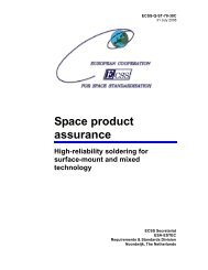
Figure 1 presents the results computed with equation 1<br />
for modelling propellant pressure in the tank in<br />
function of number of gas purges and time.<br />
According to the computation (Fig.1) the liquid<br />
propellant residual is all in vapour form after three gas<br />
purge cycles and it would take a total of 28 gas purge<br />
cycles to reach a <strong>MMH</strong> concentration of 0.1 ppm [6,<br />
6].<br />
The ROSETTA <strong>MMH</strong> tank was decontaminated with<br />
nitrogen and helium gas purges [8], Fig 1. After 27<br />
nitrogen gas purge cycles the measured <strong>MMH</strong> level<br />
was between 0.5 and 3 ppm, which is well in<br />
accordance with the prediction. It was then decided to<br />
change nitrogen gas to helium gas in order to achieve a<br />
high concentration of helium at the end of<br />
decontamination process. Yet, the measurements made<br />
on samples taken after a total of 28 and 30 gas cycles<br />
were indicating <strong>MMH</strong> concentrations between 4 and<br />
13 ppm, which was confusing. Later it became obvious<br />
that the Dräger tubes that were used to determine the<br />
<strong>MMH</strong> level, gave a higher response with helium than<br />
with nitrogen.<br />
Pressure fraction [ppm]<br />
1.E+05<br />
1.E+04<br />
1.E+03<br />
1.E+02<br />
1.E+01<br />
1.E+00<br />
1.E-01<br />
1.E-02<br />
1st GAS PURGE<br />
Fraction of <strong>MMH</strong> in the nitrogen purging gas:<br />
Predicted and Measured in function of number of gas purges<br />
0 1 2 3<br />
Time [days]<br />
4 5 6 7 8 9<br />
5th GAS PURGE<br />
9th GAS PURGE<br />
Pressure ratio of <strong>MMH</strong> in nitrogen purging gas, 3.5 bar<br />
Pressure ratio of <strong>MMH</strong> in nitrogen purging gas, 1.5 bar<br />
Measured average<br />
13th GAS PURGE<br />
Figure 1: Pressure ratio of <strong>MMH</strong> vapour in nitrogen<br />
purging gas: predicted and measured. Predicted: The<br />
partial pressure ratio of the <strong>MMH</strong> propellant in the<br />
tanks is assumed to be constant during one purge<br />
operation, but since the purging pressure varies<br />
between 1.5 bar and 3.5 bar, the pressure ratio of<br />
<strong>MMH</strong> in the purging gas actually varies: when the<br />
purging pressure is high the ratio of <strong>MMH</strong> vapour<br />
pressure is low. Measured: The “x” signs on the graph<br />
indicate the measured values in ppm in 1 bar, the<br />
yellow triangle is the average of the measured values.<br />
Although the finally measured <strong>MMH</strong> concentrations in<br />
helium gas (2.5, 0.8, 0.8 ppm) were higher than<br />
expected, the <strong>MMH</strong> concentration level was<br />
considered acceptable and the tank was pressurized to<br />
blanket pressure.<br />
17th GAS PURGE<br />
21st GAS PURGE<br />
<br />
29th GAS PURGE<br />
33rd GAS PURGE<br />
37th GAS PURGE<br />
1.E+05<br />
1.E+04<br />
1.E+03<br />
1.E+02<br />
1.E+01<br />
1.E+00<br />
1.E-01<br />
1.E-02
Lessons learned [8]:<br />
o <strong>MMH</strong> tank decontamination with nitrogen gas<br />
cycling is feasible and results are in good<br />
agreement with predictions (efficiency factor k)<br />
provided that tank internal configuration is not<br />
too complicated and strict discipline is adhered<br />
to.<br />
o S/C heaters for tank and connected piping may<br />
not be needed provided that the ambient<br />
temperature in the facility can be raised to 24-<br />
25ºC<br />
o The Dräger tube readings were different when<br />
using helium gas as compared to readings with<br />
nitrogen gas. It is therefore advisable to<br />
complete the decontamination process with<br />
nitrogen gas before any gas exchange to helium.<br />
o It is recommended to use a “virgin” ground half<br />
coupling and a (very) short adaptor pipe for<br />
sampling once a low level of contamination, say<br />
better 10 ppm, has been achieved. The ground<br />
half coupling and connections on the Ground<br />
Support Equipment (GSE) include filters and<br />
soft seal material that – during off-loading – can<br />
become soaked with or locally retain higher<br />
concentration of propellant that may negatively<br />
affect the sampling results.<br />
3. <strong>NTO</strong>/<strong>MON</strong> TANK <strong>DECONTAMINATION</strong><br />
3.1 Hazards of <strong>MON</strong> Tank Decontamination with<br />
Water<br />
The oxidiser used on Rosetta is Nitrogen Tetroxide<br />
(<strong>NTO</strong>, N2O4) containing one percent Nitrogen<br />
Monoxide (NO), therefore the oxidiser is called Mixed<br />
Oxides of Nitrogen <strong>MON</strong>-1.<br />
<strong>NTO</strong>, which is the major part of <strong>MON</strong>-1 reacts with<br />
water in large excess and forms nitric acid (HNO3) and<br />
nitrous acid (HNO2) according to equation 2: [10]<br />
N2O4 + n H2O => HNO3 + HNO2 + n H2O (2)<br />
Nitrous acid may undergo decomposition according to<br />
equation 3.<br />
3HNO2 => HNO3 + 2 NO + H2O (3)<br />
It has been reported on several occasions that nitric<br />
acid HNO3 and in particular Red Fuming Nitric Acid<br />
(RFNA) causes Stress Corrosion Cracking (SCC) in<br />
titanium alloys [10], [11], and [12]. RFNA is nitric acid<br />
that contains 0.5-20% dinitrogen oxide NO2 and 2-3 %<br />
free water.<br />
3.2 Hazards of <strong>NTO</strong>/<strong>MON</strong> Tank Decontamination<br />
with Nitrogen Gas Purges<br />
Because of the high liquid vapour pressure of <strong>MON</strong>-1<br />
(1.12 bar @ 22 ºC), most of the <strong>MON</strong>-1 propellant can<br />
be removed by vaporisation with nitrogen gas purge<br />
cycles similarly to <strong>MMH</strong>.<br />
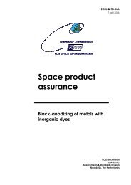
The <strong>MON</strong>-1 pressure decay can be predicted applying<br />
<strong>MON</strong>-1 liquid vapour pressure in equation 1 and<br />
having the low and high purging pressures as<br />
previously (from 1.5 bar to 3.5 bar), see figure 2. It had<br />
been assumed that <strong>MON</strong>-1 off-loading leaves 0.13dm 3<br />
liquid residual with its vapour pressure in the tank;<br />
hence the total mass of <strong>MON</strong>-1 residuals is 4.8 kg.<br />
Since the nitrogen purging gas contains 11ppmv water<br />
as impurity, nitric acid formation is possible in gas<br />
phase. In Fig. 2 the nitric acid (NHO3) level had been<br />
computed as a worst-case of nitric acid formation,<br />
assuming that all the available water and nitrogen<br />
tetroxide form NHO3.<br />
Pressure fraction [ppm]<br />
1.E+06<br />
1.E+05<br />
1.E+04<br />
1.E+03<br />
1.E+02<br />
1.E+01<br />
1.E+00<br />
1.E-01<br />
1.E-02<br />
1.E-03<br />
1.E-04<br />
1.E-05<br />
1.E-06<br />
1st GAS PURGE<br />
Fraction of <strong>MON</strong>-1 residuals in outlet purging gas<br />
6th GAS PURGE<br />
11th GAS PURGE<br />
16th GAS PURGE<br />
21st GAS PURGE<br />
26th GAS PURGE<br />
<strong>MON</strong>-1 in nitrogen purging gas in 3.5 bar<br />
HNO3 originated from wet nitrogen purging gas, assuming that all the water<br />
reacts with <strong>MON</strong>-1<br />
HNO3 from water equivalent of the propellant residuals, assumed being<br />
removed similarly to the propellant, in 3.5 bar<br />
WATER in the outlet purging gas<br />
Figure 2: Decontamination of ROSETTA <strong>MON</strong>-1 tank<br />
with nitrogen gas purges.<br />
As modelled in Fig. 2, after 20 gas purges the <strong>MON</strong>-1<br />
vapour concentration is in the same order of magnitude<br />
as that of water. At this point, although the gas<br />
concentrations are weak, it may be possible to have a<br />
situation where the majority of the nitrogen tetroxide<br />
reacts with water and forms nitric acid, in other words<br />
the situation is approaching red fuming nitric acid<br />
(RFNA) conditions. Then the condition may become<br />
31st GAS PURGE<br />
36th GAS PURGE<br />
41st GAS PURGE<br />
46th GAS PURGE
favourable for SCC in the micro crevices of the<br />
propellant tank, which were formed during<br />
manufacturing of the tank and widened during its<br />
pressurization.<br />
Since nitric acid enhances SCC in titanium alloys and<br />
insertion of water (liquid or vapour) in the <strong>MON</strong>-tank<br />
forms nitric acid, a decontamination procedure that<br />
minimises nitric acid formation and hence reduces<br />
SCC risk to the Reaction Control System (RCS) is<br />
introduced.<br />
3.3 <strong>NTO</strong>/<strong>MON</strong> Tank Decontamination with Water<br />
and Isopropylalcohol (IPA)<br />
As a precaution against having favourable conditions<br />
for SCC, a decontamination procedure with gaseous<br />
nitrogen, liquid water and liquid IPA purges is<br />
proposed to avoid the identified risks.<br />
The <strong>MON</strong>-tank emergency Off-loading and<br />
Decontamination procedure proposed for ROSETTA<br />
consists of the following activities 1 to 8:<br />
1. Liquid oxidant off –load: Depressurisation of the<br />
<strong>MON</strong>-1 tank from flight level (about 14.4 bar) to about<br />
9 bar, off-loading of the liquid <strong>MON</strong>-1 oxidant and<br />
further reduction in tank pressure to 1.5 bar. This will<br />
leave about 0.13dm 3 liquid <strong>MON</strong>-1 and <strong>MON</strong>-1<br />
vapour in the tank.<br />
2. Four nitrogen gas exchange cycles: As modelled in<br />
Figure 2, most of the residual oxidant can be removed<br />
with nitrogen gas purge cycles. The assumed 0.13dm 3<br />
liquid residual can be removed with one gas purge<br />
cycle (pressurising the tank to 3.5 bar and<br />
depressurising it to 1.5 bar). Four nitrogen gas purge<br />
cycles are proposed in order to remove all the liquid<br />
propellant and to minimise the remaining propellant in<br />
vapour form before inserting liquid water to the tank.<br />
With four gas purge cycles there is no danger of RFNA<br />
conditions.<br />
3. Tank loading with water: Loading of the tank with<br />
water to 97 % fill level. Any possible liquid residuals<br />
on the tank inner surfaces are being taken up and<br />
diluted by the water. It had been reported [13] that the<br />
reactions 2 and 3 are slow in vapour phase. Therefore,<br />
the remaining <strong>MON</strong>-1 vapours most likely reside on<br />
the top of the liquid water in the ullage volume and are<br />
expelled through the tank gas port on top as liquid<br />
water is being introduced to the tank through the liquid<br />
port at the bottom. This way the <strong>MON</strong>-1 content in the<br />
tank is reduced to about 3% of the value at the start of<br />
the water loading.<br />
4. Nitrogen gas exchange cycles in the ullage: The<br />
small ullage volume on top of the liquid water is<br />
purged with 11 nitrogen gas purge cycles in order to<br />
further reduce the propellant vapour concentration on<br />
top of the water and to minimise the total amount of<br />
oxidant residuals (and nitrous and nitric acid).<br />
5. Water off-load: Water is off-loaded from the tank<br />
leaving 0.13dm 3 liquid residual.<br />
6. Tank loading with IPA: Because water has a low<br />
vapour pressure at room temperature, it would be a<br />
lengthy process to remove water (and nitric acid)<br />
residuals with nitrogen gas purges. Therefore, after<br />
liquid water removal the tank is filled with IPA to 97<br />
% fill level. It is assumed that all the liquid water<br />
residuals containing <strong>MON</strong> oxidant residuals in the<br />
form of NHO3 become dissolved and diluted in IPA.<br />
7. IPA off-load: IPA is off-loaded, leaving 0.13dm 3<br />
liquid residual in the tank. This IPA residual contains a<br />
fraction of water residual and a (very) small fraction of<br />
oxidant residuals.<br />
8. Nitrogen gas purge cycles: According to [6] CSG<br />
require tank decontamination to 3 ppm <strong>MON</strong> before<br />
permission can be given for the transfer of the<br />
spacecraft to building S1. This level would be achieved<br />
after IPA off-loading. The maximum permitted values<br />
for IPA is 25 ppm and for water 10 ppm.<br />
Approximately 20-25 gas cycles will be needed in<br />
order to achieve required cleanliness level [9].<br />
Pressure fraction [ppm]<br />
1.E+06<br />
1.E+05<br />
1.E+04<br />
1.E+03<br />
1.E+02<br />
1.E+01<br />
1.E+00<br />
1.E-01<br />
1.E-02<br />
1.E-03<br />
1.E-04<br />
1.E-05<br />
Beginning<br />
4th GAS PURGE<br />
Pressure fraction of residuals in <strong>MON</strong> tank<br />
After liquid water<br />
removal<br />
4th GAS PURGE<br />
After IPA removal<br />
0 1 2 3 4 5 6 7 8 9<br />
time [days]<br />
4th GAS PURGE<br />
8th GAS PURGE<br />
12th GAS PURGE<br />
16th GAS PURGE<br />
20th GAS PURGE<br />
1.E+06<br />
Pressure fraction of <strong>MON</strong> in<br />
3.5 bar purging gas [ppm]<br />
1.E+05<br />
1.E+04Pressure<br />
fraction of HNO3 in<br />
3.5 bar purging gas,<br />
1.E+03assuming<br />
that all <strong>MON</strong><br />
reacts to form nitric acid<br />
1.E+02<br />
[ppm]<br />
Pressure fraction of IPA in<br />
purging gas [ppm]<br />
1.E+01<br />
1.E+00<br />
Pressure fraction of water in<br />
purging gas [ppm]<br />
1.E-01<br />
1.E-02<br />
Pressure fraction of water in<br />
1.E-03purging<br />
gas containing no<br />
water [ppm]<br />
1.E-04<br />
1.E-05<br />
Figure 3 Pressure fraction of oxidant, water and IPA<br />
residuals in function of decontamination operations.<br />
HNO3 level is as worst case, assuming all available<br />
water and oxidant react to form HNO3.
Figure 3 presents the residuals levels in the oxidant<br />
tank in function of decontamination operations and<br />
time. As a worst-case approximation, is assumed that<br />
all the oxidant vapour residuals are dissolved in water<br />
during water fill-up (action no 3.). In practise, the<br />
majority of the oxidant residuals will be removed with<br />
nitrogen gas purge cycles in the ullage on top of liquid<br />
water. It is assumed that IPA residuals can be removed<br />
with gaseous nitrogen purge cycles according to the<br />
equation 1 and that the water residuals in IPA<br />
(containing oxidant residuals) are removed at the same<br />
rate as IPA.<br />
4. CONCLUSIONS<br />
A procedure for the decontamination of the <strong>MMH</strong> tank<br />
with nitrogen gas cycles has been developed and<br />
assessed to decontaminate the ROSETTA <strong>MMH</strong> tank<br />
successfully. The number of nitrogen gas cycles<br />
needed to reach the required cleanliness level can be<br />
approximated with the equation presented.<br />
A new procedure for <strong>MON</strong> tank decontamination has<br />
been developed and proposed in order to minimize tank<br />
damage potential, since water and nitrogen tetroxide<br />
react to form nitrous and nitric acid, which can cause<br />
stress corrosion cracking in titanium alloys. The<br />
proposed procedure suggests removing most of the<br />
oxidant with nitrogen gas exchange cycles before<br />
inserting liquid water and performing gas exchange<br />
cycles in the small ullage volume on top of the water.<br />
Water residuals will then be dissolved, diluted and<br />
removed with IPA. Final drying of the tank will then<br />
be performed with nitrogen gas cycles.<br />
The lessons learned during the <strong>MMH</strong> tank<br />
decontamination shall be taken into account and<br />
incorporated in future decontamination procedures.<br />
5. REFERENCES<br />
1. Eckart Schmidt, Hydrazine and its derivatives, 2 nd<br />
edition, Wiley Interscience, 2001<br />
2. Inter Office Memorandum, Chemical Aspects of<br />
Purging Rosetta Propellant Tanks of Propellants<br />
with Water and IPA, MPC/2182/KJ, K. Jokela,<br />
Jan. 2003<br />
3. Inter-office communication I. Kälsch / K. Jokela<br />
4. Astrium, Rosetta FM RCS Simulant Offload and<br />
Post Mechanical Test Report, RO-MMB-TR-<br />
3123, Issue 1, p. 13<br />
5. Alenia, Artemis <strong>MMH</strong> Off-Loading, NCR ART<br />
2345, ALS<br />
6. Astrium, Rosetta Propellant Off-Load Working<br />
Meeting, RO-MMB-MN-3974, 23 & 24 Jan 2003<br />
7. Inter Office Memorandum, ROSETTA Propellant<br />
Tank Post Off-Load Decontamination,<br />
MPC/2190/KJ, K. Jokela, Apr 2003.<br />
8. Minutes of Meeting, Rosetta Project, Post <strong>MMH</strong><br />
Off-Loading Results Review, RO-ESK-MN-1026,<br />
14. May 2003, I. Kälsch<br />
9. Inter Office memorandum, ROSETTA – <strong>MON</strong><br />
Tank Emergency Off-Load, Expected<br />
Contamination Levels of Tank and Effluent<br />
Liquids, IK/ROS/11-05-03, I. Kälsch, May 2003.<br />
10. USAF Propellant Handbooks, Nitric<br />
Acid/Nitrogen Tetroxide Oxidisers, Vol II, Martin<br />
Marietta Corporation, 1977<br />
11. L. L. Gilbert and C. W. Funk, Explosions of<br />
Titanium and Fuming Nitric Acid Mixtures, Metal<br />
Progress, Nov 1956, pages 93-96<br />
12. R. H. Jones, Stress-Corrosion Cracking, ASM<br />
International, 1992<br />
13. A. Dadieu, Raketentreibstoffe, Springer-Verlag,<br />
1968