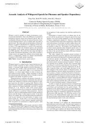
A New Delayless Subband Adaptive Filtering Algorithm for Active ...
A New Delayless Subband Adaptive Filtering Algorithm for Active ...
A New Delayless Subband Adaptive Filtering Algorithm for Active ...

You also want an ePaper? Increase the reach of your titles
YUMPU automatically turns print PDFs into web optimized ePapers that Google loves.
1038 IEEE TRANSACTIONS ON AUDIO, SPEECH, AND LANGUAGE PROCESSING, VOL. 17, NO. 5, JULY 2009<br />
A <strong>New</strong> <strong>Delayless</strong> <strong>Subband</strong> <strong>Adaptive</strong> <strong>Filtering</strong><br />
<strong>Algorithm</strong> <strong>for</strong> <strong>Active</strong> Noise Control Systems<br />
Ali A. Milani, Student Member, IEEE, Issa M. S. Panahi, Senior Member, IEEE, and<br />
Philipos C. Loizou, Senior Member, IEEE<br />
Abstract—<strong>Subband</strong> adaptive filtering (SAF) techniques play a<br />
prominent role in designing active noise control (ANC) systems.<br />
They reduce the computational complexity of ANC algorithms,<br />
particularly, when the acoustic noise is a broadband signal and the<br />
system models have long impulse responses. In the commonly used<br />
uni<strong>for</strong>m-discrete Fourier trans<strong>for</strong>m (DFT) -modulated (UDFTM)<br />
filter banks, increasing the number of subbands decreases the<br />
computational burden but can introduce excessive distortion,<br />
degrading per<strong>for</strong>mance of the ANC system. In this paper, we propose<br />
a new UDFTM-based adaptive subband filtering method that<br />
alleviates the degrading effects of the delay and side-lobe distortion<br />
introduced by the prototype filter on the system per<strong>for</strong>mance.<br />
The delay in filter bank is reduced by prototype filter design and<br />
the side-lobe distortion is compensated <strong>for</strong> by oversampling and<br />
appropriate stacking of subband weights. Experimental results<br />
show the improvement of per<strong>for</strong>mance and computational complexity<br />
of the proposed method in comparison to two commonly<br />
used subband and block adaptive filtering algorithms.<br />
Index Terms—<strong>Active</strong> noise control (ANC), discrete Fourier<br />
trans<strong>for</strong>m (DFT), filter bank, subband adaptive filter.<br />
I. INTRODUCTION<br />
ACTIVE noise control (ANC) is a method of cancelling<br />
a noise signal in an acoustic cavity by generating an<br />
appropriate anti-noise signal via canceling loudspeakers. Due<br />
to recent advances in wireless technology, new applications of<br />
ANC have emerged, e.g., incorporating ANC in cell phones,<br />
Bluetooth headphones, and MP3 players, to mitigate the environmental<br />
acoustic noise and there<strong>for</strong>e improve the speech<br />
and music quality. For practical purposes, ANC as a real-time<br />
adaptive signal processing method should meet the following<br />
requirements: 1) minimum computational complexity (lower<br />
computational delay and power consumption), 2) stability and<br />
robustness to input noise dynamics, and 3) maximum noise<br />
attenuation.<br />
Manuscript received August 13, 2008; revised January 12, 2009. Current version<br />
published June 10, 2009. This work was supported in part by a subcontract<br />
from UT Southwestern Medical Center at Dallas, funded by the Department<br />
of Veterans Affairs through VA IDIQ contract number VA549-P-0027 awarded<br />
and administered by the Dallas, TX, VA Medical Center. The content of this<br />
paper does not necessarily reflect the position or the policy of the Veterans Administration<br />
or the Federal government, and no official endorsement should be<br />
inferred. The associate editor coordinating the review of this manuscript and<br />
approving it <strong>for</strong> publication was Prof. Stephen J. Elliott.<br />
The authors are with the Department of Electrical Engineering, University<br />
of Texas at Dallas, Richardson, TX 75080 USA (e-mail: ali.a.milani@student.<br />
utdallas.edu; issa.panahi@utdallas.edu; loizou@utdallas.edu).<br />
Digital Object Identifier 10.1109/TASL.2009.2015691<br />
1558-7916/$25.00 © 2009 IEEE<br />
Fig. 1. Feed-<strong>for</strong>ward FxNLMS algorithm, where ” ƒ@A is an estimate of ƒ@A.<br />
Acoustical and electrical signal transmission path models<br />
such as those encountered in realistic ANC applications, e.g.,<br />
the primary path and the secondary path (see Fig. 1),<br />
usually have long impulse responses [1], [2]. Consequently,<br />
noise cancellation algorithms require long adaptive filters, resulting<br />
in significant computational burden. The computational<br />
complexity can be reduced by using frequency-domain filtering<br />
techniques based on decomposition, processing, and reconstructing<br />
the signals using filter banks such as subband adaptive<br />
filtering (SAF) and block adaptive filtering (BAF) techniques.<br />
SAF techniques have been used in other audio applications<br />
such as speech enhancement and hearing aids [3]–[5]. Among<br />
the SAF methods [1], [6], [7], the delayless SAF introduced by<br />
Morgan and Thi (MT) in [1] provides a better approach to meet<br />
the a<strong>for</strong>ementioned requirements <strong>for</strong> ANC system. Merched<br />
and Sayed [2] introduced a BAF algorithm named discrete<br />
Fourier trans<strong>for</strong>m multidelay adaptive filter (DFT-MDF). This<br />
algorithm exploits the properties of circulant matrices to implement<br />
a high-per<strong>for</strong>mance block adaptive processing algorithm.<br />
DFT-MDF (as it will be shown later) per<strong>for</strong>ms well with a<br />
small block lengths (or small number of subbands).<br />
Zhou et al. [8] proposed an ANC system that requires no<br />
secondary path identification, whereby to cancel a single tone<br />
at frequency , the adaptive filter, denoted by (see<br />
Fig. 1), needs to estimate the ratio of not<br />
and individually, and the phase is set to either 0 or 180<br />
by trial and error. Expanding on this concept, [8] shows that a<br />
non-tonal noise signal can be canceled by decomposing it into<br />
very narrow subbands and treating each subband like a tonal<br />
component. According to [8], the narrower the subbands are,<br />
i.e., the higher the number of subbands, the better should be the<br />
per<strong>for</strong>mance of the system. Hence, an appropriate SAF technique<br />
with a large number of subbands may be used to avoid secondary<br />
path identification. The BAF algorithms are not suitable<br />
<strong>for</strong> this purpose since the adaptive filters within do not directly<br />
operate in subbands; they are used when a good estimate of the
MILANI et al.: NEW DELAYLESS SUBBAND ADAPTIVE FILTERING ALGORITHM FOR ANC SYSTEMS 1039<br />
secondary path is available. As we will show, the per<strong>for</strong>mance<br />
of BAF techniques deteriorates <strong>for</strong> a large number of subbands.<br />
Consequently, not only is a good estimate of the secondary path<br />
required, but the reduction of computational complexity is also<br />
limited by the small number of subbands.<br />
In general, the SAF methods offer a good alternative approach<br />
to meet ANC system requirements, due to their inherent spectral<br />
decomposition and downsampling operations. Since the spectral<br />
dynamic range and eigenvalue spread of the covariance matrix<br />
of noise signal decrease in each subband, the per<strong>for</strong>mance, i.e.,<br />
convergence rate, noise attenuation level, and stability of the<br />
ANC system, improves using SAF techniques [9]. Hence, one<br />
expects that increasing the number of subbands (or block length)<br />
should improve the per<strong>for</strong>mance.<br />
The delayless SAF scheme in an ANC system involves the<br />
decomposition of input noise (i.e., the reference signal) and<br />
error signals into subbands using analysis filter banks, and combining<br />
the subband weights into a full-band noise canceling<br />
filter by a synthesis filter bank called weight stacking. Typically,<br />
a linear-phase finite-impulse response (FIR) low-pass filter (i.e.,<br />
prototype filter) is designed and modulated <strong>for</strong> the design of<br />
such filter banks [10]. The filter must be designed so that the<br />
side-lobe effect and spectral leakage are minimized. The latter<br />
requires a high-order FIR filter, introducing a long delay, which<br />
increases with as the bandwidth shrinks. The long delay and<br />
side-lobe interference introduced by the prototype filter degrade<br />
the per<strong>for</strong>mance of SAF algorithms <strong>for</strong> large , limiting the<br />
computational saving that can be obtained by increasing the<br />
number of subbands [2]. Improving the system per<strong>for</strong>mance<br />
and reducing the computational burden by increasing has inspired<br />
the work presented herein.<br />
In this paper, we first demonstrate that the increased delay<br />
degrades the system per<strong>for</strong>mance more than that of the spectral<br />
leakage (or side-lobe effects) in a uni<strong>for</strong>m subband filtering<br />
method. It is shown how the spectral leakage can be reduced<br />
by choosing a proper decimation factor and weight stacking<br />
methodology. We then present a new SAF algorithm that reduces<br />
computational complexity by increasing the number of<br />
subbands without degrading the per<strong>for</strong>mance of the ANC<br />
system. The per<strong>for</strong>mance of the proposed method is compared<br />
with those of MT and DFT-MDF methods in [1] and [2]. The<br />
results show that the maximum noise attenuation level (NAL) of<br />
the proposed method is higher than that of MT and comparable<br />
to that of the DFT-MDF method. However, the new method<br />
achieves the maximum NAL with much lower computational<br />
complexity and higher robustness than the other two methods.<br />
This paper is organized as follows. Section II defines the notation<br />
and definitions used in the paper. The general structure<br />
of delayless subband adaptive filtering algorithm and the per<strong>for</strong>mance<br />
limiting factors of the MT algorithm are discussed in<br />
Section III. In Section IV, we present the new subband adaptive<br />
filtering method. Per<strong>for</strong>mance comparison and experimental results<br />
are presented in Section V. Concluding remarks are in<br />
Section VI.<br />
II. NOTATION AND DEFINITIONS<br />
A block diagram of a feed-<strong>for</strong>ward filtered-input normalized<br />
least mean square (FxNLMS) ANC system is shown in Fig. 1,<br />
where is the acoustic noise signal measured by a reference<br />
microphone and is called the reference signal. Noise cancellation<br />
is achieved acoustically around an error microphone<br />
whose output is . is the transfer function modeling<br />
the primary path. The noise signal after passing through is<br />
called which is the noise signal to be canceled. The ANC<br />
adaptive algorithm determines the noise canceling filter ,<br />
whose output is . The output of the secondary path is<br />
. Filter is an estimate of , which we assume errorless,<br />
i.e., . The following notation is used in the<br />
paper.<br />
NAL Noise attenuation level.<br />
Time (sample) index.<br />
Number of subbands.<br />
<strong>Subband</strong> index, .<br />
Decimation factor used in analysis<br />
Length of the prototype low-pass filter.<br />
Weight vector (coefficients) of the FIR noise<br />
canceling filter .<br />
Length of .<br />
Weight vector <strong>for</strong> the th subband filter.<br />
Length of each subband adaptive filter.<br />
z-trans<strong>for</strong>m of .<br />
z-trans<strong>for</strong>m of .<br />
Modulo- operation.<br />
Bold lower case and bold upper case letters denote vectors<br />
and matrices respectively.<br />
III. DELAYLESS SUBBAND ANC METHODS<br />
A delayless subband adaptive filtering technique involves the<br />
following.[1]<br />
1) A full-band filter that filters the input signal.<br />
2) Decomposition of input and error signals into subbands.<br />
3) Decimation in subbands.<br />
4) <strong>Adaptive</strong> filters working in subbands.<br />
5) A weight stacking method to combine all subbands weights<br />
into a full-band filter.<br />
Signal decomposition is done by analysis filter banks. The<br />
adaptive filters operate in subbands and all subband weights<br />
are stacked together to make the full-band noise canceling filter<br />
. Stacking in general is done by passing the subband weights<br />
through a synthesis filter bank. The analysis and synthesis filter<br />
banks must be designed such that they make a perfect reconstruction<br />
pair [10]. Fig. 2 shows the delayless subband adaptive<br />
filtering scheme used in the ANC FxNLMS algorithm [1]. In this<br />
method, is filtered by , generating . and<br />
are then filtered into subbands named and<br />
using the analysis filter bank with a decimation factor .<br />
Filter is given by<br />
(1)
1040 IEEE TRANSACTIONS ON AUDIO, SPEECH, AND LANGUAGE PROCESSING, VOL. 17, NO. 5, JULY 2009<br />
Fig. 2. Feed-<strong>for</strong>ward delayless subband FxNLMS structure.<br />
where, is the transfer function of the th analysis bandpass<br />
filter with linear phase and length . In each subband,<br />
weights denoted by are computed using an adaptive algorithm<br />
such as NLMS, i.e.,<br />
where is the complex conjugation operation, is the step size,<br />
is a small positive value, and<br />
(2)<br />
(3)<br />
(4)<br />
All s are then stacked together to construct by employing<br />
weight stacking methods. This architecture is delayless<br />
since is not explicitly <strong>for</strong>med as a combination of subband<br />
adaptive filters outputs. The analysis filter banks developed<br />
so far have been mainly based on uni<strong>for</strong>m DFT modulated<br />
(UDFTM) filter banks [1] and tree structured filter banks like the<br />
Hadamard trans<strong>for</strong>m [6]. Several methods, such as fast Fourier<br />
trans<strong>for</strong>m (FFT)-1 [1], FFT-2 [11], DFT-FIR [11], and linear<br />
weight trans<strong>for</strong>m [12], have been suggested <strong>for</strong> weight stacking.<br />
UDFTM filter banks are composed of a set of bandpass filters<br />
created by modulating a linear phase lowpass (prototype)<br />
filter. The low-pass filter has a bandwidth of and the central<br />
frequencies of the bandpass filters are at , <strong>for</strong><br />
. To exploit the computational advantage of<br />
the FFT algorithm, usually and the length of the low-pass<br />
filter are chosen to be powers of 2. The spectral leakage (inband-aliasing)<br />
in the analysis filter banks is minimized when the<br />
prototype low-pass filter has a very low stop-band energy [10]<br />
and a linear phase with an even-symmetric impulse response<br />
[13]. To reduce the stop-band energy <strong>for</strong> a bandwidth of ,<br />
the filter order should increase. Fig. 3 compares the frequency<br />
responses of such low-pass filters designed <strong>for</strong> lengths of ,<br />
, and <strong>for</strong> using the Remez algorithm. As shown<br />
<strong>for</strong> a bandwith of , a low-pass filter of length is needed<br />
[1]. Since the low-pass filter should have linear phase, its inherent<br />
delay increases with , deteriorating the per<strong>for</strong>mance<br />
Fig. 3. Low-pass filters designed by Remez algorithm with length w, Pw, and<br />
Rw (thin lines), compared with the frequency response of the proposed filter<br />
(bold line) <strong>for</strong> w aIT.<br />
of the SAF algorithm [2], [14]. The effect of delay is more pronounced<br />
when the length of is increased <strong>for</strong> primary and<br />
secondary paths with long impulse responses. Since long requires<br />
a lower step size, the adaptive system becomes more sensitive<br />
to distortions caused by spectral leakage and delay [14].<br />
The prototype filter design is an optimization problem that<br />
jointly minimizes the delay and stop-band energy. These two<br />
phenomena are inversely related, i.e., increasing the length of<br />
the low-pass filter reduces the spectral leakage and increases the<br />
delay and vice versa. The methods used to design such prototype<br />
filters are based on quadrature optimization [13], minmax optimization<br />
[15], [16], least square[17], and homomorphic filtering<br />
[18], [19]. Although, both spectral leakage and delay have direct<br />
impact on the delayless SAF per<strong>for</strong>mance, our experiments<br />
show that the effect of delay is more prominent. Hence, one can<br />
tradeoff the spectral leakage <strong>for</strong> the reduced delay with no per<strong>for</strong>mance<br />
degradation.<br />
In the next section, a new SAF algorithm based on UDFTM<br />
filter banks is presented. The proposed lowpass (prototype) filter<br />
in the UDFTM filter banks is of length and delay ,<br />
and hence, introduces less delay and side-lobe attenuation than<br />
other cases, as shown in Fig. 3. As will be shown, the side-lobe<br />
interference is compensated <strong>for</strong> by oversampling in subbands<br />
and proper weight stacking of the subband weights. Unlike existing<br />
SAF and BAF algorithms, the proposed SAF algorithm<br />
improves the system per<strong>for</strong>mance and reduces the computational<br />
complexity as increases.<br />
IV. PROPOSED SAF METHOD<br />
In the proposed SAF method, the analysis stage is a UDFTM<br />
filter bank. The decimation factor in the filter bank is . The<br />
bandwidth of the linear-phase low-pass prototype FIR filter is<br />
. The prototype filter has the length of introducing a<br />
delay of in the filter banks. This delay is less than<br />
the delay presented in the methods of [1] and [6] resulting in the<br />
improved per<strong>for</strong>mance in our algorithm. The description of the<br />
new method is as follows.
MILANI et al.: NEW DELAYLESS SUBBAND ADAPTIVE FILTERING ALGORITHM FOR ANC SYSTEMS 1041<br />
A. Proposed Uni<strong>for</strong>m DFT Modulated Filter Bank<br />
Using the UDFTM structure, we propose the following lowpass<br />
prototype FIR filter <strong>for</strong> the filter banks<br />
The resulting filter bank is the simplest FIR perfect reconstruction<br />
filter bank [10] which is made by<br />
with a frequency response of<br />
otherwise<br />
The magnitude response of has been plotted in Fig. 3<br />
<strong>for</strong> . The attenuation of its first side-lobe is about 13 dB<br />
relative to its main lobe. The first zero-crossing of is<br />
at giving a bandwidth of about . Hence, the decimation<br />
factor should not exceed in order to avoid spectral<br />
aliasing. For the proposed UDFTM filter banks, is defined<br />
by<br />
where is the DFT matrix of order . The central frequencies<br />
of the bandpass filters , are located at <strong>for</strong><br />
, which is shown in Fig. 4(a). An important<br />
advantage of this UDFTM filter bank is that it can be realized<br />
using a tapped delay line of length followed by an inverse<br />
FFT block.<br />
The in (5) has linear phase with a delay of .<br />
By choosing (5), the delay in UDFTM filter bank and attenuation<br />
of side-lobes are less than those given in [1], [6]. To alleviate<br />
the interference of the side-lobes on the system per<strong>for</strong>mance,<br />
we choose an appropriate decimation factor and per<strong>for</strong>m<br />
the weight stacking as follows. We note that oversampling in<br />
subbands helps to mitigate the spectral aliasing caused by the<br />
side-lobes during the decimation operation. In our approach,<br />
the decimation factor is chosen to be . After decimation<br />
by a factor of , only the side-lobes in intervals of<br />
(<strong>for</strong> , see Fig. 3) interfere with the<br />
main-lobe over the interval [0, ]. Since these side-lobes are<br />
attenuated by more than 20 dB, the interference in the main-lobe<br />
reduces more than 7 dB (compared to 13 dB from the first sidelobe).<br />
As a direct result of using a decimation factor of ,<br />
the bandpass filters with the same values of will have<br />
the same spectra. Hence, there are four types of output spectra<br />
which are used to design an appropriate weight stacking method.<br />
The concept is illustrated in Fig. 4(b)–(e), where a triangular<br />
spectrum is used to symbolically represent the spectrum of each<br />
bandpass filter given by (6).<br />
.<br />
.<br />
(5)<br />
(6)<br />
(7)<br />
(8)<br />
Fig. 4. Symbolic representation of spectra. (a) Frequency response of UDFT<br />
filter bank. After decimation by h a waR, the spectral shapes change according<br />
to the subband index , i.e., (b) @@AA a H, (c) @@AA a I, (d)<br />
@@AA aP, (e) @@AA aQ.<br />
B. Proposed Weight Stacking Method<br />
Among the synthesis filter banks commonly used <strong>for</strong> weight<br />
stacking are the computationally efficient delayless methods of<br />
FFT-1 [1] and FFT-2 [11]. In these methods, the DFT bins of<br />
, denoted by , are divided equally among subbands.<br />
Since the DFT bins of of length , are uni<strong>for</strong>mly distributed<br />
in , i.e. <strong>for</strong> , each subband contributes<br />
to bins of . The bins of in the th subband<br />
are selected from the DFT bins of the th subband weight,<br />
denoted by , and is reconstructed by computing the<br />
inverse DFT of . Bin selection is done based on the relation<br />
between the frequency response of and .<br />
As shown in Fig. 4(a), the central frequencies of the UDFTM<br />
bandpass filters are located at . The corresponding<br />
has the bandwidth of and <strong>for</strong> and<br />
, respectively, and the adjacent bandpass filters share a<br />
bandwidth of . After decimation by , the spectral<br />
shapes of and resemble those shown in
1042 IEEE TRANSACTIONS ON AUDIO, SPEECH, AND LANGUAGE PROCESSING, VOL. 17, NO. 5, JULY 2009<br />
Fig. 4(b)–(e), depending on the value of . The resultant<br />
follows the same spectral pattern too.<br />
As illustrated in Fig. 4(a)–(e), the bins of are selected as<br />
follows.<br />
1) For the interval , they are equal to the bins of<br />
in the interval .<br />
2) For the interval and<br />
, they are equal to the bins of in the interval<br />
and .<br />
3) For the interval and<br />
, they are equal to the bins of in the interval<br />
.<br />
4) For the interval and<br />
, they are equal to the bins of in the interval<br />
.<br />
5) For the interval and<br />
, they are equal to the bins of in the interval<br />
.<br />
6) For the interval , they are equal to the bins<br />
of in the interval .<br />
The bin selection is based on the spectral shapes exemplified in<br />
Fig. 4(a)–(e), and the fact that the bins are distributed among the<br />
subbands proportional to their bandwidths. Mathematically, the<br />
proposed DFT bin selection and stacking methods are expressed<br />
as follows.<br />
Proposed FFT-1 weight stacking method (PFFT-1)<br />
Proposed FFT-2 weight stacking method (PFFT-2)<br />
(9)<br />
(10)<br />
The PFFT-2 method uses twice as many DFT points than that<br />
of PFFT-1, which results in reduced weight stacking distortion<br />
[20]. Furthermore, unlike the original methods of FFT-1 [1] and<br />
FFT-2 [11], the frequency responses of PFFT-1 and PFFT-2 do<br />
not have nulls at , resulting in improved per<strong>for</strong>mance of<br />
the ANC system. In the proposed methods, the length of each<br />
subband adaptive filter should be at least <strong>for</strong><br />
PFFT-1 and <strong>for</strong> PFFT-2, since only one fourth<br />
of the total DFT bins in each subband are trans<strong>for</strong>med. The<br />
PFFT-2 uses zero-padding to compute a DFT of size .<br />
V. COMPUTATIONAL COMPLEXITY<br />
The computational complexity of the proposed subband filtering<br />
technique is calculated by counting the number of real<br />
multiplications required <strong>for</strong> the following operations.<br />
1) Decimation by the factor .<br />
2) Calculation of the filter bank outputs. Only<br />
subbands are considered since is real.<br />
3) Weight update operation <strong>for</strong> calculating adaptive<br />
filters.<br />
4) Weight stacking and calculation of which includes<br />
FFT operations to compute s and an<br />
IFFT operation to compute .<br />
TABLE I<br />
COMPUTATIONAL COMPLEXITY FOR THE PROPOSED METHOD IN TERMS OF<br />
NUMBER OF REAL MULTIPLICATIONS PER INPUT SAMPLE<br />
Fig. 5. Comparison of computational complexity per input sample versus<br />
number of subbands @wA, <strong>for</strong> x aIHPR. MT diverges <strong>for</strong> w bIPV.<br />
Table I summarizes the computational complexity per input<br />
sample <strong>for</strong> the operations listed above. The total complexity is<br />
plotted in Fig. 5 versus the number of subbands . The plot<br />
is <strong>for</strong> the PFFT-2 method with , as it results<br />
in better per<strong>for</strong>mance than that of PFFT-1. For comparison<br />
purposes, we have included the computational complexity of<br />
the MT [1] and DFT-MDF [2] algorithms in Fig. 5. As shown,<br />
the computational complexities of all methods reduce almost<br />
exponentially with . The proposed technique compared to the<br />
other methods <strong>for</strong> small values of has higher computational<br />
complexity. However, as it will be discussed in Section V,<br />
the new technique works very well with a larger number of<br />
subbands, improving the system per<strong>for</strong>mance and attaining<br />
lower complexity, whereas the MT method fails to converge<br />
and the per<strong>for</strong>mance of the DFT-MDF method deteriorates.<br />
VI. EXPERIMENTAL RESULTS<br />
For the system shown in Fig. 2, the noise attenuation level is<br />
calculated by<br />
(11)<br />
where is the frame length, and is the ratio of the norms of<br />
the noise and the error at the canceling point after the<br />
ANC adaptive algorithm has converged. Since white noise is not
MILANI et al.: NEW DELAYLESS SUBBAND ADAPTIVE FILTERING ALGORITHM FOR ANC SYSTEMS 1043<br />
Fig. 6. Test bed used to measure € @A and ƒ@A. The targeted application is<br />
active noise cancelation of the acoustic noise in MRI machines.<br />
Fig. 7. Measured actual impulse responses (a) Primary path € @A. (b) Secondary<br />
path ƒ@A.<br />
predictable, it is usually used as a worst case test of ANC systems.<br />
The per<strong>for</strong>mance of the proposed algorithm is evaluated<br />
and compared to those of the MT and DFT-MDF algorithms<br />
using a zero-mean unit-variance white noise as the input signal.<br />
A series of simulations were conducted to evaluate the per<strong>for</strong>mance<br />
of an ANC system using the proposed subband filtering<br />
technique. For this purpose, transfer functions of the primary<br />
and secondary paths were measured <strong>for</strong> a test bed using the large<br />
half-cylindrical tube shown in Fig. 6. Fig. 7 shows the measured<br />
impulse responses of the primary and secondary paths. The experiment<br />
was to run the ANC system in Fig. 2 with the measured<br />
TABLE II<br />
MAXIMUM ATTAINABLE VALUE OF NAL AND ITS CORRESPONDING VALUE OF<br />
w FOR DIFFERENT ADAPTIVE FILTERING ALGORITHMS. x a IHPR<br />
Fig. 8. MSE decay versus time sample <strong>for</strong> the MT, DFT-MDF, and the proposed<br />
methods <strong>for</strong> the best operating conditions given in Table II.<br />
Fig. 9. NAL versus step size ", <strong>for</strong> the MT, DFT-MDF, and the proposed<br />
methods, using the best operating conditions given in Table II.<br />
and <strong>for</strong> samples of white input noise and measure<br />
the output NALs and MSE curves <strong>for</strong> each algorithm. The<br />
experiment was repeated <strong>for</strong> different values of , , and step<br />
size . The final results were calculated by averaging over 100<br />
independent runs. The value resulted in the highest<br />
NAL value. The maximum obtainable value of NAL and corresponding<br />
value of were chosen as the best operating condition<br />
<strong>for</strong> each algorithm in our experiments. The results are<br />
shown in Table II. The proposed method achieves 17.92 dB of<br />
noise reduction with subbands resulting in much<br />
lower complexity than the other two methods.<br />
As shown in Fig. 8, the convergence rate of the proposed algorithm<br />
with PFFT-2 is faster than that of the MT algorithm.<br />
The DFT-MDF has an initial fast convergence rate that slows
1044 IEEE TRANSACTIONS ON AUDIO, SPEECH, AND LANGUAGE PROCESSING, VOL. 17, NO. 5, JULY 2009<br />
Fig. 10. Comparing NAL versus step size " of (a) proposed method, (b) and DFT-MDF, <strong>for</strong> different numbers of subbands @w A.<br />
down after some time. The proposed method compared to the<br />
DFT-MDF method has slower convergence but they both reach<br />
steady state values almost simultaneously. The fast initial convergence<br />
rate of DFT-MDF method is due to the fact that its<br />
UDFTM filter bank is the eigenmatrix of the blocks processed<br />
by the DFT-MDF algorithm [2].<br />
Fig. 9 shows the maximum achievable NAL values versus<br />
<strong>for</strong> the proposed, MT, and DFT-MDF algorithms. The plots<br />
are <strong>for</strong> the values of given in Table II. As shown, the MT<br />
method is very sensitive to the step-size value: a small change<br />
in reduces the maximum achievable value of NAL. The MT<br />
method diverges <strong>for</strong> in our experiments. Conversely,<br />
the proposed and the DFT-MDF algorithms show significant<br />
robustness to variations of . Fig. 10 compares the NAL variation<br />
of the proposed and DFT-MDF methods <strong>for</strong> different numbers<br />
of subbands. As shown, the robustness of the proposed algorithm<br />
increases with , while the DFT-MDF algorithm becomes<br />
more sensitive to variations of . The proposed method<br />
works very well <strong>for</strong> a large number of subbands. It achieves its<br />
maximum per<strong>for</strong>mance (i.e., maximum NAL value) at<br />
, reducing the computational complexity drastically. However,<br />
The MT algorithm diverges <strong>for</strong> . Although the<br />
DFT-MDF works with a large number of subbands, but it becomes<br />
more sensitive to , as shown in Fig. 10(b), and a small<br />
change in degrades its per<strong>for</strong>mance significantly.<br />
VII. CONCLUSION<br />
Acoustic paths such as those encountered in ANC application<br />
usually have long impulse responses, which require longer<br />
adaptive filters <strong>for</strong> noise cancellation. <strong>Subband</strong> adaptive filters<br />
working with a large number of subbands has been shown to be a<br />
good solution to this problem. The focus of this paper was to design<br />
such a high-per<strong>for</strong>mance SAF algorithm. The per<strong>for</strong>mance<br />
limiting factors of existing SAF structures were found to be due<br />
to the inherent delay and side-lobes of the prototype filter in the<br />
analysis filter banks. Hence, the analysis filter banks were modified<br />
to reduce the inherent delay. A new weight stacking trans<strong>for</strong>m<br />
was designed to alleviate the interference introduced by the<br />
side-lobes. The modifications resulted in a new subband method<br />
that, unlike existing methods, improves the per<strong>for</strong>mance and reduces<br />
the computational complexity <strong>for</strong> a large number of subbands.<br />
Experimental results showed that the proposed method<br />
outper<strong>for</strong>med the two commonly used SAF and BAF methods.<br />
REFERENCES<br />
[1] D. R. Morgan and J. C. Thi, “A delayless subband adaptive filter architecture,”<br />
IEEE Trans. Signal Process., vol. 43, no. 8, pp. 1819–1830,<br />
Aug. 1995.<br />
[2] R. Merched and A. H. Sayed, “An embedding approach to frequencydomain<br />
and subband adaptive filtering,” IEEE Trans. Signal Process.,<br />
vol. 48, no. 9, pp. 2607–2619, Sep. 2000.<br />
[3] P. Loizou, Speech Enhancement: Theory and Practice. Boca Raton,<br />
FL: CRC, 2007.<br />
[4] V. R. Ramachandran, G. Kannan, A. A. Milani, and I. M. S. Panahi,<br />
“Speech enhancement in functional MRI environment using adaptive<br />
sub-band algorithms,” in Proc. ICASSP’07, 2007, pp. II-341–II-344.<br />
[5] P. Loizou and K. Kokkinakis, “<strong>Subband</strong>-based blind signal processing<br />
<strong>for</strong> source separation in convolutive mixtures of speech,” in Proc.<br />
ICASSP’07, 2007, pp. IV-917–IV-920.<br />
[6] N. Hirayamaa, H. Sakai, and S. Miyagi, “<strong>Delayless</strong> subband adaptive<br />
filtering using the hadamard trans<strong>for</strong>m,” IEEE Trans. Acoust., Speech,<br />
Signal Process., vol. 47, pp. 1731–1734, Jun. 1999.<br />
[7] P. Eneroth, “Joint filterbanks <strong>for</strong> echo cancellation and audio coding,”<br />
IEEE Trans. Speech Audio Process., vol. 11, no. 4, pp. 342–354, Jul.<br />
2003.<br />
[8] D. Zhou and V. DeBrunner, “A new active noise control algorithm that<br />
requires no secondary path identification based on the SPR property,”<br />
IEEE Trans. Signal Process., vol. 55, no. 5, pp. 1719–1729, May 2007.<br />
[9] J. Shynk, “Frequency-domain and multirate adaptive filtering,” IEEE<br />
Signal Process. Mag., vol. 9, no. 1, pp. 14–37, Jan. 1992.<br />
[10] P. Vaidyanathan, Multirate Systems and Filter Banks. Englewood<br />
Cliffs, NJ: Prentice-Hall, 1993.<br />
[11] J. Huo, S. Nordholm, and Z. Zang, “<strong>New</strong> weight trans<strong>for</strong>m schemes <strong>for</strong><br />
delayless subband adaptive filtering,” in Proc. GLOBECOM’01, <strong>New</strong><br />
York, Nov. 2001, pp. 197–201.<br />
[12] L. Larson, J. de Haan, and I. Claesson, “A new subband weight trans<strong>for</strong>m<br />
<strong>for</strong> delayless subband adaptive filtering structures,” in Proc. Digital<br />
Signal Process. Workshop, Aug. 2002, pp. 201–206.<br />
[13] J. M. de Haan, N. Grbic, I. Claesson, and S. E. Nordholm, “Filter bank<br />
design <strong>for</strong> subband adaptive microphone arrays,” IEEE Trans. Speech<br />
Audio Process., vol. 11, no. 1, pp. 14–23, Jan. 2003.<br />
[14] A. H. Sayed, Fundamentals of <strong>Adaptive</strong> <strong>Filtering</strong>. <strong>New</strong> York: Wiley,<br />
2003.<br />
[15] Z. Lin and Y. Liu, “Design of complex fir filters with reduced group<br />
delay error using semidefinite programming,” IEEE Trans. Signal<br />
Process., vol. 13, no. 9, pp. 529–532, Sep. 2006.<br />
[16] R. Venkataramani and Y. Bresler, “Filter design <strong>for</strong> MIMO sampling<br />
and reconstruction,” IEEE Trans. Signal Process., vol. 51, no. 12, pp.<br />
3164–3167, Dec. 2003.
MILANI et al.: NEW DELAYLESS SUBBAND ADAPTIVE FILTERING ALGORITHM FOR ANC SYSTEMS 1045<br />
[17] Y. C. Lim, J. Lee, C. K. Chen, and R. Yang, “A weighted least squares<br />
algorithm <strong>for</strong> quasi-equiripple FIR and IIR digital filter design,” IEEE<br />
Trans. Signal Process., vol. 40, no. 3, pp. 551–558, Mar. 1992.<br />
[18] H. Gustafsson, S. E. Nordholm, and I. Claesson, “Spectral subtraction<br />
using reduced delay convolution and adaptive averaging,” IEEE Trans.<br />
Speech Audio Process., vol. 9, no. 8, pp. 799–807, Nov. 2001.<br />
[19] A. V. Oppenheim and R. W. Schafer, Discrete-Time Signal Processing,<br />
2nd ed. Englewood Cliffs, NJ: Prentice-Hall, 1999.<br />
[20] A. A. Milani, G. Kannan, I. Panahi, R. Briggs, and K. Gopinath,<br />
“Weight stacking analysis of delayless subband adaptive algorithms<br />
<strong>for</strong> fMRI active noise cancellation,” in Proc. IEEE Dallas EMBS<br />
Workshop, Dallas, Nov. 2007, pp. 134–137.<br />
Ali A. Milani received the B.S. degree in electrical<br />
engineering from the Sharif University of Technology,<br />
Tehran, Iran, in 2001 and the M.S. degree<br />
from the School of Electrical Engineering and<br />
Computer Science, University of Texas at Dallas,<br />
Richardson, in 2007, where he is currently pursuing<br />
the Ph.D. degree.<br />
His research interests are audio, speech and multimedia<br />
signal processing, and embedded multimedia<br />
systems. Since 2005, as a member of the Statistical<br />
Signal Processing Research Lab, he has been<br />
working on adaptive noise cancellation, speech enhancement, and microphone<br />
arrays.<br />
Mr. Milani is the recipient of the outstanding paper awards from the Acoustical<br />
Society of America and Analog Devices, Inc.<br />
Issa M. S. Panahi (S’84–M’88–SM’07) received the<br />
Ph.D. degree in electrical engineering from the University<br />
of Colorado at Boulder in 1988.<br />
He joined the faculty of the University of Texas at<br />
Dallas (UTD), Richardson, after working in industry<br />
<strong>for</strong> several years, and he is now an Assistant Professor<br />
in the Department of Electrical Engineering.<br />
He is a Director of the Statistical Signal Processing<br />
and Acoustic Research Laboratories at UTD. His research<br />
areas of interest include MIMO digital signal<br />
processing, source separation, signal estimation,<br />
system identification, noise cancellation, speech enhancement, and embedded<br />
DSP systems. He was a Research Scientist in the Geophysical Signal Processing<br />
Group at Bellaire Research Lab, Shell Oil Development, Houston, TX<br />
(1988-1991), and a DSP Chief Architect, Worldwide Applications Manager,<br />
Senior Member Of The Technical Staff, Chief Technology Officer, and Advance<br />
Systems Development Manager in the embedded DSP systems business unit<br />
at Texas Instruments, Inc., in Houston, (1991- 2000). He was an Application<br />
Manager with the Wireless/OMAP Group, Texas Instruments, Dallas, be<strong>for</strong>e<br />
joining UTD in 2001. He holds one US patent. He is author/coauthor of several<br />
Texas Instruments books, and has published numerous conference, journal, and<br />
technical papers.<br />
Dr. Panahi cofounded the IEEE-Dallas Chapter of Engineering in Medicine<br />
and Biology Society (EMBS) in 2006. He has been Vice-Chair of the IEEE-<br />
Dallas Chapters of the EMBS and Signal Processing (SP) Societies since 2006.<br />
He was the Secretary and Treasurer (2004), and Program Chair (2005) of the<br />
IEEE Signal Processing chapter in Dallas. He was recipient of the “2005 Outstanding<br />
Service Award” from the Dallas Section of the IEEE.<br />
Philipos C. Loizou received the B.S., M.S., and<br />
Ph.D. degrees, all in electrical engineering, from<br />
Arizona State University (ASU), Tempe, in 1989,<br />
1991, and 1995, respectively.<br />
From 1995 to 1996, he was a Postdoctoral Fellow<br />
in the Department of Speech and Hearing Science<br />
at ASU, working on research related to cochlear implants.<br />
He was an Assistant Professor at the University<br />
of Arkansas at Little Rock from 1996 to 1999.<br />
He is now a Professor and holder of the Cecil and<br />
Ida Green Chair in the Department of Electrical Engineering,<br />
University of Texas at Dallas, Richardson. His research interests are<br />
in the areas of signal processing, speech processing, and cochlear implants. He<br />
is author of the book Speech Enhancement: Theory and Practice (CRC, 2007).<br />
Dr. Loizou is currently an Associate Editor of the IEEE TRANSACTIONS<br />
ON BIOMEDICAL ENGINEERING and the International Journal Of Audiology.<br />
He was an Associate Editor of the IEEE TRANSACTIONS ON SPEECH AND<br />
AUDIO PROCESSING (1999-2002) and the IEEE SIGNAL PROCESSING LETTERS<br />
(2006-2008). He is currently a member of the Speech Technical Committee of<br />
the IEEE Signal Processing Society.