SAC Clutch tool set SAC KupplungswerkzeugSatz Outil de ... - Unior
SAC Clutch tool set SAC KupplungswerkzeugSatz Outil de ... - Unior SAC Clutch tool set SAC KupplungswerkzeugSatz Outil de ... - Unior
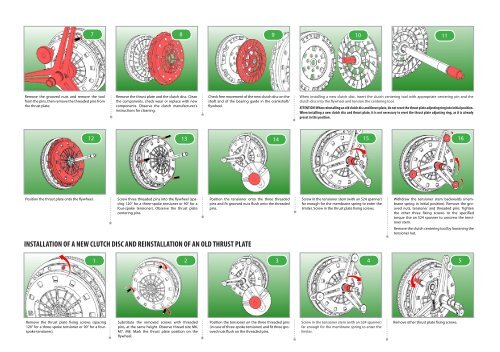
Remove the grooved nuts and remove the tool from the pins, then remove the threaded pins from the thrust plate. Position the thrust plate onto the flywheel. 7 8 9 10 11 12 Remove the thrust plate and the clutch disc. Clean the components, check wear or replace with new components. Observe the clutch manufacturer's instructions for cleaning. Screw three threaded pins into the flywheel (spacing 120° for a three-spoke tensioner or 90° for a four-spoke tensioner). Observe the thrust plate centering pins. Check free movement of the new clutch disc on the shaft and of the bearing guide in the crankshaft/ flywheel. Position the tensioner onto the three threaded pins and fit grooved nuts flush onto the threaded pins. INSTALLATION OF A NEW CLUTCH DISC AND REINSTALLATION OF AN OLD THRUST PLATE Remove the thrust plate fixing screws (spacing 120° for a three-spoke tensioner or 90° for a fourspoke tensioner). Substitute the removed screws with threaded pins, at the same height. Observe thread size M6, M7, M8. Mark the thrust plate position on the flywheel. Position the tensioner on the three threaded pins (in case of three-spoke tensioner) and fit three grooved nuts flush on the threaded pins. When installing a new clutch disc, insert the clutch centering tool with appropriate centering pin and the clutch disc into the flywheel and tension the centering tool. ATTENTION! When reinstalling an old clutch disc and thrust plate, do not reset the thrust plate adjusting ring into initial position. When installing a new clutch disc and thrust plate, it is not necessary to reset the thrust plate adjusting ring, as it is already preset in this position. 13 14 15 16 Screw in the tensioner stem (with an S24 spanner) far enough for the membrane spring to enter the limiter. Screw in the thrust plate fixing screws. 1 2 3 4 Screw in the tensioner stem (with an S24 spanner) far enough for the membrane spring to enter the limiter. Withdraw the tensioner stem backwards (membrane spring in initial position). Remove the grooved nuts, tensioner and threaded pins. Tighten the other three fixing screws to the specified torque Use an S24 spanner to unscrew the tensioner stem. Remove the clutch centering tool by loosening the tensioner nut. Remove other thrust plate fixing screws. 5
Withdraw the tensioner stem fully backwards (membrane spring in initial position). Use an S24 spanner. 11 Position the tensioner on the three threaded pins (in case of three-spoke tensioner) and fit three grooved nuts flush on the threaded pins. Screw in the threaded pins (spacing 120° for a three-spoke tensioner or 90° for a four-spoke tensioner). Observe the thrust plate centering pins. 6 7 8 9 10 Remove other thrust plate fixing screws. Remove the thrust plate and the clutch disc. Clean Check free movement of the new clutch disc on the the components, check wear or replace with new shaft and of the bearing guide in the crankshaft/ components. Observe the clutch manufacturer's instructions for cleaning. flywheel. 12 Screw in the stem until the thrust plate adjusting ring begins to turn clockwise, to the right, on its own. This is noticed both visually as well as through a rattling sound. Caution: With the membrane spring fully loose or fully tightened, the adjusting ring is blocked. In such a case, apply withdrawal tools. Position the tensioner onto the three threaded pins and fit grooved nuts flush onto the threaded pins. Clamp the return tool into the thrust plate opening next to the return spring, then turn the adjusting ring backwards by opening the return tool into the initial position, counterclockwise. Remove the tensioner stem and dismount the tensioner. Remove the return tool from the thrust plate and remove the thrust plate. Caution: Do not apply pressure on the return tool through the original stem, to avoid bending of return arms. Screw the tensioner stem (with an S24 spanner) enough for the membrane spring to enter the limiter. Screw thrust plate fixing screws. Withdraw the tensioner stem backwards (with an S24 spanner) (membrane spring in initial position). Mount the old thrust plate onto the flywheel, by means of three threaded pins. Do not insert the clutch disc. Observe the mounting mark made. 13 14 15 Insert the clutch centering tool with appropriate centering pin and the clutch into the flywheel and tension the centering tool. 16 17 18 19 Position the thrust plate onto the flywheel. 20 Remove the grooved nuts, tensioner and threaded pins. Tighten the other fixing screws to the specified moment. Remove the clutch centering tool by loosening the tensioner nut.
Remove the grooved nuts and remove the <strong>tool</strong><br />
from the pins, then remove the threa<strong>de</strong>d pins from<br />
the thrust plate.<br />
Position the thrust plate onto the flywheel.<br />
7 8 9<br />
10<br />
11<br />
12<br />
Remove the thrust plate and the clutch disc. Clean<br />
the components, check wear or replace with new<br />
components. Observe the clutch manufacturer's<br />
instructions for cleaning.<br />
Screw three threa<strong>de</strong>d pins into the flywheel (spacing<br />
120° for a three-spoke tensioner or 90° for a<br />
four-spoke tensioner). Observe the thrust plate<br />
centering pins.<br />
Check free movement of the new clutch disc on the<br />
shaft and of the bearing gui<strong>de</strong> in the crankshaft/<br />
flywheel.<br />
Position the tensioner onto the three threa<strong>de</strong>d<br />
pins and fit grooved nuts flush onto the threa<strong>de</strong>d<br />
pins.<br />
INSTALLATION OF A NEW CLUTCH DISC AND REINSTALLATION OF AN OLD THRUST PLATE<br />
Remove the thrust plate fixing screws (spacing<br />
120° for a three-spoke tensioner or 90° for a fourspoke<br />
tensioner).<br />
Substitute the removed screws with threa<strong>de</strong>d<br />
pins, at the same height. Observe thread size M6,<br />
M7, M8. Mark the thrust plate position on the<br />
flywheel.<br />
Position the tensioner on the three threa<strong>de</strong>d pins<br />
(in case of three-spoke tensioner) and fit three grooved<br />
nuts flush on the threa<strong>de</strong>d pins.<br />
When installing a new clutch disc, insert the clutch centering <strong>tool</strong> with appropriate centering pin and the<br />
clutch disc into the flywheel and tension the centering <strong>tool</strong>.<br />
ATTENTION! When reinstalling an old clutch disc and thrust plate, do not re<strong>set</strong> the thrust plate adjusting ring into initial position.<br />
When installing a new clutch disc and thrust plate, it is not necessary to re<strong>set</strong> the thrust plate adjusting ring, as it is already<br />
pre<strong>set</strong> in this position.<br />
13 14 15 16<br />
Screw in the tensioner stem (with an S24 spanner)<br />
far enough for the membrane spring to enter the<br />
limiter. Screw in the thrust plate fixing screws.<br />
1 2 3 4<br />
Screw in the tensioner stem (with an S24 spanner)<br />
far enough for the membrane spring to enter the<br />
limiter.<br />
Withdraw the tensioner stem backwards (membrane<br />
spring in initial position). Remove the grooved<br />
nuts, tensioner and threa<strong>de</strong>d pins. Tighten<br />
the other three fixing screws to the specified<br />
torque Use an S24 spanner to unscrew the tensioner<br />
stem.<br />
Remove the clutch centering <strong>tool</strong> by loosening the<br />
tensioner nut.<br />
Remove other thrust plate fixing screws.<br />
5


