MCP23008/MCP23S08 - Microchip
MCP23008/MCP23S08 - Microchip
MCP23008/MCP23S08 - Microchip

You also want an ePaper? Increase the reach of your titles
YUMPU automatically turns print PDFs into web optimized ePapers that Google loves.
<strong>MCP23008</strong>/<strong>MCP23S08</strong><br />
1.2 Power-on Reset (POR)<br />
The on-chip POR circuit holds the device in reset until<br />
VDD has reached a high enough voltage to deactivate<br />
the POR circuit (i.e., release the device from Reset).<br />
The maximum VDD rise time is specified in Section 2.0<br />
“Electrical Characteristics”.<br />
When the device exits the POR condition (releases<br />
reset), device operating parameters (i.e., voltage,<br />
temperature, serial bus frequency, etc.) must be met to<br />
ensure proper operation.<br />
1.3 Serial Interface<br />
This block handles the functionality of the I 2 C<br />
(<strong>MCP23008</strong>) or SPI (<strong>MCP23S08</strong>) interface protocol.<br />
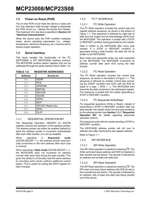
The MCP23X08 contains eleven registers that can be<br />
addressed through the serial interface block (Table 1-2):<br />
TABLE 1-2: REGISTER ADDRESSES<br />
Address Access to:<br />
00h IODIR<br />
01h IPOL<br />
02h GPINTEN<br />
03h DEFVAL<br />
04h INTCON<br />
05h IOCON<br />
06h GPPU<br />
07h INTF<br />
08h INTCAP (Read-only)<br />
09h GPIO<br />
0Ah OLAT<br />
1.3.1 SEQUENTIAL OPERATION BIT<br />
The Sequential Operation (SEQOP) bit (IOCON<br />
register) controls the operation of the address pointer.<br />
The address pointer can either be enabled (default) to<br />
allow the address pointer to increment automatically<br />
after each data transfer, or it can be disabled.<br />
When operating in Sequential mode<br />
(IOCON.SEQOP = 0), the address pointer automatically<br />
increments to the next address after each byte<br />
is clocked.<br />
When operating in Byte mode (IOCON.SEQOP = 1),<br />
the MCP23X08 does not increment its address<br />
counter after each byte during the data transfer. This<br />
gives the ability to continually read the same address<br />
by providing extra clocks (without additional control<br />
bytes). This is useful for polling the GPIO register for<br />
data changes.<br />
1.3.2 I 2 C INTERFACE<br />
1.3.2.1 I 2 C Write Operation<br />
The I 2 C Write operation includes the control byte and<br />
register address sequence, as shown in the bottom of<br />
Figure 1-1. This sequence is followed by eight bits of<br />
data from the master and an Acknowledge (ACK) from<br />
the <strong>MCP23008</strong>. The operation is ended with a STOP<br />
or RESTART condition being generated by the master.<br />
Data is written to the <strong>MCP23008</strong> after every byte<br />
transfer. If a STOP or RESTART condition is<br />
generated during a data transfer, the data will not be<br />
written to the <strong>MCP23008</strong>.<br />
Byte writes and sequential writes are both supported<br />
by the <strong>MCP23008</strong>. The <strong>MCP23008</strong> increments its<br />
address counter after each ACK during the data<br />
transfer.<br />
1.3.2.2 I 2 C Read Operation<br />
The I 2 C Read operation includes the control byte<br />
sequence, as shown in the bottom of Figure 1-1. This<br />
sequence is followed by another control byte (including<br />
the START condition and ACK) with the R/W bit<br />
equal to a logic 1 (R/W = 1). The <strong>MCP23008</strong> then<br />
transmits the data contained in the addressed register.<br />
The sequence is ended with the master generating a<br />
STOP or RESTART condition.<br />
1.3.2.3 I 2 C Sequential Write/Read<br />
For sequential operations (Write or Read), instead of<br />
transmitting a STOP or RESTART condition after the<br />
data transfer, the master clocks the next byte pointed to<br />
by the address pointer (see Section 1.3.1 “Sequential<br />
Operation Bit” for details regarding sequential<br />
operation control).<br />
The sequence ends with the master sending a STOP or<br />
RESTART condition.<br />
The <strong>MCP23008</strong> address pointer will roll over to<br />
address zero after reaching the last register address.<br />
Refer to Figure 1-1.<br />
1.3.3 SPI INTERFACE<br />
1.3.3.1 SPI Write Operation<br />
The SPI Write operation is started by lowering CS. The<br />
Write command (slave address with R/W bit cleared) is<br />
then clocked into the device. The opcode is followed by<br />
an address and at least one data byte.<br />
1.3.3.2 SPI Read Operation<br />
The SPI Read operation is started by lowering CS. The<br />
SPI read command (slave address with R/W bit set) is<br />
then clocked into the device. The opcode is followed by<br />
an address, with at least one data byte being clocked<br />
out of the device.<br />
DS21919E-page 6 © 2007 <strong>Microchip</strong> Technology Inc.