Optoelectronics with Carbon Nanotubes
Optoelectronics with Carbon Nanotubes
Optoelectronics with Carbon Nanotubes

Create successful ePaper yourself
Turn your PDF publications into a flip-book with our unique Google optimized e-Paper software.
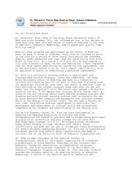
(a) (b)<br />
Figure IV-3. Electroluminescence spectra. (a) EL spectrum of a CNT diode recorded<br />
at different drain-source currents IDS between 30 and 230 nA. Gate biases of VGS1 = -<br />
9 V and VGS2 = +9 V were applied. The data can be fitted well <strong>with</strong> two Gaussians<br />
and, at low currents, we extract widths of ~45 meV (FWHM) for the individual<br />
contributions. Besides the strong exciton emission (labeled X), a weaker satellite<br />
peak at lower energy is observed (LX). It is attributed to localized exciton emission.<br />
(b) Comparison between EL spectra at two different gate biases (normalized). Solid<br />
green line: VGS1 = -7 V, VGS2 = +7 V; dashed grey line: VGS1 = -9 V, VGS2 = +9 V.<br />
The spectral width of the -/+ 7 V measurement is only ~35 meV (FWHM). (c) Red<br />
symbols: The free exciton emission (X) shows an approximately linear increase <strong>with</strong><br />
current. Green symbols: Localized exciton emission (LX). The EL saturates as the<br />
current exceeds 100 nA. The EL versus current dependence shows no threshold<br />
behavior (see also Figure IV-2 (b)). The dashed lines are guides to the eye. (d) Same<br />
as (c), but for a different device. After Ref. 11.<br />
Figure IV-3 (c) depicts the current dependence of the X and LX emission intensity as<br />
extracted from Figure IV-3 (a). The free exciton emission X shows a linear increase <strong>with</strong> current<br />
74<br />
(c) (d)