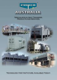
Layout 1 (Page 3) - Tasman Cooling Towers
Layout 1 (Page 3) - Tasman Cooling Towers
Layout 1 (Page 3) - Tasman Cooling Towers

You also want an ePaper? Increase the reach of your titles
YUMPU automatically turns print PDFs into web optimized ePapers that Google loves.
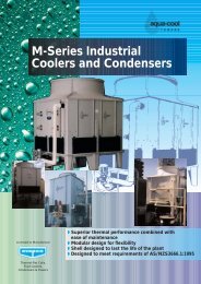
Member <strong>Cooling</strong> Technology Institute<br />
AFT - A Series <strong>Cooling</strong> <strong>Towers</strong><br />
With Exclusive:<br />
> Aqua-Seal and Aqua-Clean technology<br />
> 10 Year Warranty on FRP components<br />
> 3 Year Warranty on motors<br />
Designed and built in Australia to conform with the<br />
requirements of AS/NZS 3666
Advanced Technology Design<br />
Aqua-Cool <strong>Towers</strong> and Evapco are dedicated to applying<br />
their experience and resources to the advancement of<br />
cooling tower technology. The AFT-A Series range of<br />
cooling towers is a reflection of this commitment.<br />
Applying Aqua-Cool <strong>Towers</strong> proven thermal design<br />
capabilities and unique engineering and production skills in<br />
composite construction has lead to the development of the<br />
AFT-A Series range of cooling towers. The AFT includes the<br />
smaller direct drive units from 177 kW to 830 kW and the<br />
larger belt drive units from 745 kW to 2700 kW.<br />
The AFT-A Series is a heavy-duty cooling tower which saves<br />
space, blends easily with architectural designs and offers<br />
low operating costs. The AFT-A Series incorporates durable<br />
construction with an ease of serviceability not before seen in<br />
cooling tower design. This has been made possible with the<br />
exclusive Aqua-Seal panel design system and Aqua-<br />
Clean basin design both developed in house by Aqua-Cool<br />
<strong>Towers</strong> Pty Ltd.<br />
AFT-A units utilise an induced draft, counterflow design:<br />
making these the most efficient design cooling towers with<br />
minimum footprint. All major components, axial fans, inlet<br />
louvres, motors and wet deck fill have been selected to<br />
ensure maximum efficiency with low energy consumption.<br />
The AFT-A is designed for air conditioning and industrial<br />
water cooling applications. All components and materials<br />
were selected and tested for demanding industrial service,<br />
thus assuring the cooling tower user of long equipment life.<br />
Features And Benefits<br />
> Rigid panels with lighter weight makes site assembly<br />
The water distribution<br />
system is made of Class E<br />
PVC pipe and ABS plastic<br />
water diffusers.<br />
faster and easier. Less assembly time means lower<br />
installed costs.<br />
> The unique panel design helps prevent water leakage<br />
between the panels and makes temporary removal and<br />
replacement of access panels a simple process. This ease<br />
of removal and replacement of the access panels further<br />
reduces maintenance costs.<br />
> The smooth moulded interior presents an exceptionally<br />
easy-to-clean surface. Gel coated surfaces have been<br />
approved by the FDA for contact with food. Aqua-Cool<br />
<strong>Towers</strong> believes that the use of flow coated interior<br />
surfaces increases the risk of biological contamination by<br />
providing a relatively “rough” surface which allows slime<br />
and other biofilms to adhere more easily than on the gel<br />
coated finish.<br />
> Glass reinforcements used in the construction of the AFT<br />
A Series towers comply with ISO 2797 or DIN 61855.<br />
Resins comply with ISO 2559. Having certification to both<br />
Lloyds and Det Norski Veritas ensures the quality and<br />
life of our cooling towers’ long equipment life and reliable<br />
operation.<br />
The thermal performance of each unit is backed by a full<br />
written guarantee.<br />
These features allow us at Aqua-Cool <strong>Towers</strong> to offer a 10<br />
year warranty on FRP components and a three year warranty<br />
on the motors.<br />
2<br />
The fill is specially<br />
designed to induce<br />
highly turbulent mixing<br />
of air and water for<br />
superior heat transfer.<br />
The Aqua-Clean basin and smaller plan<br />
area requirements allow less water to be<br />
held in the unit during normal operation
Engineering Data<br />
AFT 4-66A to 8-918A<br />
AFT Shipping Operating Fan Height Length Length Inlet Outlet Drain Overflow Makep<br />
Model Weight Weight Motor Overall Overall, L1 L2 NB NB NB NB Size<br />
kg kg kW mm mm mm mm mm mm mm mm<br />
4-66A 345 855 2.2 2721 2030 1650 100 100 50 50 25<br />
4-76A 375 885 2.2 3136 2030 1650 100 100 50 50 25<br />
4-86A 357 862 4 2721 2030 1650 100 100 50 50 25<br />
4-96A 387 897 4 3136 2030 1650 100 100 50 50 25<br />
4-59A 513 1248 (2)1.5 2721 2945 2565 100 100 50 50 25<br />
4-69A 543 1278 (2)1.5 3136 2945 2565 100 100 50 50 25<br />
4-79A 555 1295 (2)2.2 2721 2945 2565 100 100 50 50 25<br />
4-89A 555 1295 (2)2.2 3136 2945 2565 100 100 50 50 25<br />
4-99A 585 1325 (2)2.2 3136 2945 2565 100 100 50 50 25<br />
4-612A 678 1648 (2)2.2 2721 3935 3555 150 150 50 50 25<br />
4-712A 705 1675 (2)2.2 3136 3935 3555 150 150 50 50 25<br />
4-812A 717 1692 (2)4 3136 3935 3555 150 150 50 50 25<br />
4-912A 744 1719 (2)4 3136 3935 3555 150 150 50 50 25<br />
8-49A 978 2193 7.5 3800 2963 2543 200 200 50 50 25<br />
8-59A 999 2214 7.5 3800 2963 2543 200 200 50 50 25<br />
8-69A 990 2205 11 3800 2963 2543 200 200 50 50 25<br />
8-79A 1014 2234 11 3800 2963 2543 200 200 50 50 25<br />
8-89A 1137 2532 11 3800 2963 2543 200 200 50 50 25<br />
8-99A 1143 2358 15 3800 2963 2543 200 200 50 50 25<br />
8-412A 1353 3043 11 3800 3878 3458 200 200 50 50 25<br />
8-512A 1218 2853 15 3800 3878 3458 200 200 50 50 25<br />
8-612A 1395 3085 11 3800 3878 3458 200 200 50 50 25<br />
8-712A 1411 3100 15 3800 3878 3458 200 200 50 50 25<br />
8-812A 1434 3125 15 3800 3878 3458 200 200 50 50 25<br />
8-912A 1450 3250 18.5 3800 3878 3458 200 200 50 50 25<br />
8-318A 1803 4283 (2)5.5 3800 5730 - 250 250 50 50 40<br />
8-418A 1734 4214 (2)7.5 3800 5730 - 250 250 50 50 40<br />
8-518A 1818 4298 (2)7.5 3800 5730 - 250 250 50 50 40<br />
8-618A 1866 4351 (2)7.5 3800 5730 - 250 250 50 50 40<br />
8-718A 1848 4328 (2)11 3800 5730 - 250 250 50 50 40<br />
8-818A 1908 4388 (2)15 3800 5730 - 250 250 50 50 40<br />
8-918A 2121 4601 (2)15 3800 5730 - 250 250 50 50 40<br />
Engineering Dimensions<br />
Dimensions shown are for use as a guide only. Certified drawings are available if required for use in<br />
construction. Plinth height of 300 mm is recommended but this will depend on relative height of the pump suction to<br />
tower outlet.<br />
3
Engineering Dimensions<br />
Sound Sensitive Applications Solutions<br />
AFT-A Series cooling towers are available with four equipment<br />
options to reduce the overall sound generated from the side or top<br />
of the tower. Each option provides various levels of sound reduction<br />
and can be used in combination to provide the lowest sound level.<br />
Consult your Aqua Cool <strong>Towers</strong>’ representative for more details.<br />
Super Low Sound Fan<br />
9 –15 dB(A) Reduction versus Standard Fan. The Aqua-Cool<br />
Super Low Sound Fan utilises a very wide chord blade design<br />
available for sound sensitive applications where the lowest sound<br />
levels are desired. The fan is a hollow core heavy duty FRP<br />
construction utilising a forward swept blade design. The Super Low<br />
Sound is capable of reducing the unit sound pressure levels 9 dB(A)<br />
to 15 dB(A), depending on specific unit selection and measurement<br />
location. The fans are high efficiency axial propeller type, developed<br />
specifically for Aqua Cool <strong>Towers</strong> Pty Ltd.<br />
Note: the Super Low Noise Fan is available on 2.4 M wide AFT-A<br />
cooling towers, AFTW closed circuit coolers and AFTC evaporative<br />
condensers.<br />
Low Sound Fan<br />
4 – 7 dB(A) reduction. The Low Sound Fan offered by Aqua Cool<br />
<strong>Towers</strong> is available as a wide chord aluminium or FRP blade design<br />
4<br />
Dimensions shown are for use as a<br />
guide only. Certified drawings are<br />
available if required for use in<br />
construction. Plinth height of 300<br />
mm is recommended but this will<br />
depend on relative height of the<br />
pump suction to tower outlet.<br />
available for sound sensitive applications where low sound levels<br />
are required. The Low Sound Fan is capable of reducing the unit<br />
sound pressure levels 4 dB(A) to 7dB(A), depending on specific unit<br />
selection and measurement locations. The fans are high efficiency<br />
axial propeller type and designed specifically for Aqua Cool <strong>Towers</strong><br />
Pty Ltd.<br />
AFT Fan Discharge Sound Attenuation<br />
Up to 10 dB(A) reduction. The AFT-A Discharge Attenuation<br />
offered by Aqua-Cool <strong>Towers</strong> is an additional option available to<br />
further reduce the sound level of the unit. The attenuator can be<br />
used with the standard AFT-A fan or in combination with the Low<br />
Sound Fan option.<br />
The discharge attenuator is a factory assembled straight sided<br />
discharge hood design to reduce the overall discharge sound levels<br />
at full fan speed 5 dB(A) to 10 dB(A), depending on specific unit<br />
and measurement locations. It is constructed of Z600 galvanised<br />
steel as standard (option available for type 304 S/S) and includes<br />
insulated walls and a low pressure drop baffling system that is<br />
acoustically lined with high density fibreglass. The discharge<br />
attenuation is self supported by the unit and is shipped loose to be<br />
mounted in the field. The discharge attenuators will have a minimal<br />
impact on thermal performance (0% - 2% derate depending on<br />
specific unit selection).
Sound Sensitive Applications Solutions<br />
Cont’d. from page 4...<br />
AFT Water Silencer<br />
Up to 7 dB(A) reduction. The water silencer option is available for<br />
all AFT-A models and is located in the falling water area of the cold<br />
water basin. The water silencer will reduce the high frequency sound<br />
associated with falling water and is capable of reducing overall sound<br />
levels 4 dB(A) to 7 dB(A) measured at 1.5 metres from the side or ends<br />
of the units. The water silencers reduce overall sound levels 9 dB(A) to<br />
<strong>Cooling</strong> Tower Selection Data<br />
Temperature<br />
12 dB(A) (depending on water loadings and louvre height) measured<br />
1.5 metres from the side or end of the unit when water is circulated<br />
with fans off.<br />
The water silencers are constructed of lightweight PVC sections and<br />
can be easily removed for access to the basin area.<br />
Hot Water ˚C 35.0 35.0 35.0 35.0 35.0 35.0 35.0 35.0 35.0 35.0 35.0 35.0 35.0 35.0 35.0 38.0 38.0 38.0 38.0 38.0 Fan<br />
Cold Water ˚C 29.5 29.5 29.5 29.5 29.5 29.5 29.5 29.5 29.5 29.5 29.5 29.5 29.5 29.5 29.5 30.0 31.0 32.0 33.0 33.0 Motor<br />
Wet Bulb ˚C 19.0 19.5 20.0 20.5 21.0 21.5 22.0 22.5 23.0 23.5 24.0 24.5 25.0 25.5 26.0 27.0 27.0 27.0 27.0 28.0 kW<br />
Flow Rate l/s<br />
AFT4-66A 20.9 20.3 19.7 19.1 18.5 17.8 17.2 16.5 15.8 15.1 14.4 13.6 12.8 12.0 11.2 8.6 11.2 14.3 18.5 16.6 2.2<br />
AFT4-76A 21.8 21.2 20.6 20.1 19.5 18.8 18.2 17.5 16.8 16.1 15.4 14.6 13.9 13.1 12.2 9.6 12.2 15.4 19.5 17.7 2.2<br />
AFT4-86A 24.0 23.3 22.6 21.9 21.2 20.5 19.7 19.0 18.1 17.3 16.5 15.6 14.7 13.8 12.8 9.9 12.8 16.4 21.2 19.0 4.0<br />
AFT4-96A 25.5 24.8 24.2 23.5 22.8 22.0 21.3 20.5 19.7 18.9 18.0 17.1 16.2 15.2 14.2 11.2 14.3 18.0 22.9 20.7 4.0<br />
AFT4-59A 30.6 29.9 29.0 28.1 27.2 26.3 25.3 24.3 23.3 22.3 21.2 20.1 18.9 17.7 16.5 12.7 16.5 21.1 27.2 24.5 (2)1.5<br />
AFT4-69A 31.3 30.5 29.7 28.9 28.0 27.1 26.2 25.2 24.2 23.2 22.2 21.1 20.0 18.8 17.5 13.9 17.6 22.2 28.1 25.5 (2)1.5<br />
AFT4-79A 34.5 33.6 32.6 31.6 30.6 29.5 28.4 27.3 26.2 25.0 23.8 22.5 21.2 19.9 18.5 14.3 18.5 23.7 30.5 27.5 (2)2.2<br />
AFT4-89A 35.3 34.4 33.4 32.4 31.5 30.4 29.3 28.2 27.1 25.9 24.7 23.5 22.2 20.8 19.4 15.1 19.4 24.7 31.5 28.5 (2)2.2<br />
AFT4-99A 35.9 35.0 34.0 33.1 32.1 31.0 30.0 28.9 27.8 26.6 25.4 24.2 22.8 21.5 20.1 15.8 20.2 25.4 32.2 29.2 (2)2.2<br />
AFT4-612A 41.8 40.7 39.5 38.3 37.1 35.8 34.4 33.1 31.7 30.3 28.8 27.3 25.7 24.1 22.4 17.3 22.4 28.8 37.0 33.4 (2)2.2<br />
AFT4-712A 43.9 42.8 41.6 40.5 39.2 37.9 36.6 35.3 33.9 32.5 31.0 29.5 27.9 26.3 24.5 19.3 24.6 31.0 39.4 35.7 (2)2.2<br />
AFT4-812A 50.3 48.9 47.5 46.0 44.5 42.9 41.3 39.8 38.0 36.3 34.5 32.7 30.8 28.8 26.8 20.6 26.8 34.4 44.4 39.9 (2)4<br />
AFT4-912A 50.3 48.9 47.6 46.2 44.8 43.3 41.9 40.3 38.7 37.1 35.4 33.6 31.8 29.9 27.9 22.0 28.1 35.4 45.0 40.8 (2)4<br />
AFT8-49A 66.0 64.3 62.5 60.7 58.8 56.9 54.9 52.9 50.8 48.6 46.3 44.0 41.5 39.1 36.4 28.4 36.5 46.3 58.8 53.3 7.5<br />
AFT8-59A 66.9 65.2 63.5 61.7 59.9 57.9 56.0 54.0 51.9 49.8 47.6 45.2 42.8 40.3 37.7 29.7 37.8 47.6 60.1 54.6 7.5<br />
AFT8-69A 73.9 71.9 70.0 67.9 65.8 63.7 61.4 59.1 56.8 54.3 51.8 49.2 46.5 43.7 40.7 31.7 40.7 51.7 65.8 59.6 11.0<br />
AFT8-79A 75.0 73.1 71.2 69.1 67.1 64.9 62.7 60.5 58.1 55.7 53.2 50.6 47.9 45.1 42.1 33.2 42.3 53.2 67.4 61.1 11.0<br />
AFT8-89A 75.6 73.8 72.0 70.0 68.0 65.9 63.9 61.6 59.4 57.1 54.6 52.1 49.4 46.7 43.7 35.1 44.1 54.8 68.5 62.6 11.0<br />
AFT8-99A 83.1 81.0 79.0 76.9 74.7 72.4 70.1 67.7 65.2 62.6 59.9 57.1 54.2 51.2 48.0 38.4 48.3 60.1 75.2 68.7 15.0<br />
AFT8-412A 88.5 86.2 83.9 81.5 79.1 76.5 73.8 71.3 68.4 65.6 62.6 59.5 56.3 53.1 49.6 39.1 49.8 62.6 79.4 72.1 11.0<br />
AFT8-512A 92.2 89.6 87.1 84.4 81.6 78.9 75.9 73.0 69.9 66.8 63.5 60.2 56.7 53.1 49.3 38.0 49.3 63.3 81.5 73.4 15.0<br />
AFT8-612A 89.6 87.4 85.2 82.9 80.5 78.0 75.6 72.9 70.2 67.5 64.6 61.5 58.4 55.2 51.7 41.5 52.1 64.7 81.1 74.0 11.0<br />
AFT8-712A 97.0 94.5 92.0 89.3 86.7 83.9 81.0 78.1 75.0 71.8 68.6 65.2 61.7 58.0 54.1 42.6 54.3 68.6 86.9 78.9 15.0<br />
AFT8-812A 98.4 96.0 93.6 91.0 88.4 85.7 83.0 80.0 77.1 74.0 70.9 67.5 64.1 60.5 56.7 45.4 57.1 71.1 89.0 81.3 15.0<br />
AFT8-912A 104.8 102.3 99.7 97.0 94.2 91.3 88.3 85.3 82.1 78.9 75.5 71.9 68.2 64.4 60.3 48.3 60.7 75.7 94.9 86.5 18.5<br />
AFT8-318A 120.1 117.1 113.9 110.7 107.4 103.9 100.4 96.9 93.1 89.3 85.2 81.0 76.7 72.3 67.6 53.4 67.9 85.2 107.9 97.9 (2)5.5<br />
AFT8-418A 125.9 122.4 119.0 115.4 111.6 107.9 103.9 99.8 95.7 91.4 87.0 82.5 77.7 72.8 67.7 52.3 67.7 86.8 111.4 100.4 (2)7.5<br />
AFT8-518A 129.6 126.3 122.7 119.1 115.4 111.7 107.7 103.8 99.6 95.3 90.8 86.2 81.5 76.6 71.3 55.8 71.5 90.8 115.6 104.6 (2)7.5<br />
AFT8-618A 131.7 128.4 124.9 121.3 117.8 113.9 110.0 106.2 102.0 97.8 93.4 88.8 84.0 79.1 73.9 58.4 74.3 93.4 118.3 107.4 (2)7.5<br />
AFT8-718A 145.2 141.4 137.6 133.4 129.2 125.1 120.5 116.0 111.4 106.6 101.6 96.4 91.1 85.6 79.7 62.2 79.8 101.6 129.4 117.0 (2)11.0<br />
AFT8-818A 162.1 157.9 153.6 149.2 144.8 140.0 135.2 130.5 125.3 120.1 114.6 108.9 103.0 97.0 90.5 71.2 90.9 114.6 145.1 131.7 (2)15.0<br />
AFT8-918A 163.9 159.9 155.8 151.7 147.3 142.8 138.2 133.5 128.4 123.4 118.0 112.5 106.8 100.8 94.4 75.6 95.1 118.4 148.4 135.3 (2)15.0<br />
5
<strong>Cooling</strong> Tower Specifications<br />
A. GENERAL: <strong>Cooling</strong> Tower Specification<br />
Furnish and install as shown on plans ____ off Aqua-Cool<br />
<strong>Towers</strong>’ AFT A Series Model ______ <strong>Cooling</strong> Tower. Each<br />
unit shall have a capacity of ____ kW Total Heat Rejection,<br />
operating at ____ l/sec water flow each from an entering<br />
water temperature at ____ °C at an entering wet bulb<br />
temperature of ____ °C.<br />
B. UNIT CONSTRUCTION<br />
The unit shall be manufactured from fibreglass reinforced<br />
polyester, with all interior surfaces, including fan cylinder,<br />
basin and casing having a moulded gel coat finish to ensure<br />
ease of cleaning.<br />
All glass reinforcements used in the construction of the<br />
cooling towers will comply with ISO 2797 or DIN 61855 and<br />
ISO 2559 and must have both Lloyds and Det Norski Veritas<br />
certification. The laminating resins will have been tested by<br />
a local authority, for certification by Lloyds.<br />
The cold water basin will have been designed specifically for<br />
use with sidestream filtration system and have dedicated<br />
points for fitment of sweeper jets. The basin shall be graded<br />
to the drain as per the requirements of AS/NZS 3666.1.<br />
The casing panel design will provide quick and easy access<br />
for maintenance.<br />
All water connections shall be fibreglass or PVC. Exterior<br />
surface only will have surfaces flow coated with UVstabilised<br />
material.<br />
The tower will be supported on legs moulded from<br />
fibreglass without the need for metal fittings or<br />
supports.The fill shall be of cross-fluted design to provide<br />
maximum surface area and minimal air pressure drop. The<br />
fill shall be in glued packs to allow easy removal. The PVC<br />
material must comply with the <strong>Cooling</strong> Tower Institute (CTI)<br />
STD 136.<br />
C. HEAT TRANSFER SECTION<br />
Water Distribution System: Each inlet shall deliver water to<br />
the distribution systems by means of a transverse header<br />
Aqua-Cool <strong>Towers</strong> Pty Ltd<br />
ABN 76 099 969 605<br />
Administration and Factory:<br />
34-42 Melbourne Road, Riverstone NSW 2765 Australia<br />
P.O. Box 436, Riverstone NSW 2765 Australia<br />
Tel: (61 2) 9627 3322 Fax: (61 2) 9627 1715<br />
Email: sales@aquacooltowers.com.au<br />
www.aquacooltowers.com.au<br />
Sydney, Melbourne, Brisbane, Adelaide, Perth, Auckland<br />
6<br />
pipe with longitudinal pipe laterals and low pressure plastic<br />
spray nozzles.<br />
Drift Eliminators: Drift Eliminators shall be designed utilising<br />
a series of sinusoidal-shaped blades. Eliminators shall be<br />
installed in easy to clean and handle modules limiting drift<br />
to less than 0.002% in compliance with AS4180.1.<br />
Eliminator blades shall be secured in end-caps to help<br />
prevent distortion and located in a horizontal position.<br />
D. MECHANICAL EQUIPMENT<br />
Fan: Fans shall be multi-blade axial flow with variable or<br />
fixed pitch manufactured from aluminium, fibreglass or<br />
polypropylene. Fan shall be direct or belt driven.<br />
Mechanical Support: The mechanical support equipment<br />
shall be of heavy gauge steel construction and shall be hot<br />
dipped galvanised, after fabrication and designed to<br />
maintain alignment of rotating parts.<br />
The mechanical support shall be installed at top of the fan<br />
cylinder. Easily removable fan guards shall be fitted and<br />
shall be a minimum of 4 mm mesh.<br />
Motor: Electric motor shall be to IP56 D Standard totally<br />
enclosed, tropic-proofed construction, designed specifically<br />
for cooling tower application.<br />
E. INLET LOUVRES<br />
Inlet louvres shall be vacuum formed from PVC to CTI STD<br />
136, designed to prevent splash-out and help inhibit<br />
sunlight entry to the unit interior. Air-inlet louvres shall be of<br />
two pass configuration installed at 90 degrees, removable<br />
and be located in PVC or optional stainless steel frames.<br />
F. TOWER CONFIGURATION<br />
Tower shall be a counter flow design so as to minimise<br />
sunlight entry into interior wetted area. Access to the water<br />
basin will be available from all four sides.<br />
G. ACCESSORIES<br />
Access ladders and platforms shall be to AS1657, supplied<br />
to suit installation.<br />
Distributed By:<br />
The manufacturer reserves the right to alter performance,<br />
specifications and design without notice.<br />
ACT.cpr/0505/2k © Aqua-Cool <strong>Towers</strong> Pty Ltd, 2005