Instruction Manual - Magnetrol International
Instruction Manual - Magnetrol International
Instruction Manual - Magnetrol International

Create successful ePaper yourself
Turn your PDF publications into a flip-book with our unique Google optimized e-Paper software.
Installation and Operating <strong>Manual</strong><br />
Model R82<br />
Pulse Burst Radar<br />
Level Transmitter<br />
software v2.0x
Read this <strong>Manual</strong> Before Installing<br />
This manual provides information on the R82 Radar transmitter. It is<br />
important that all instructions are read carefully and followed in<br />
sequence. The QuickStart Installation instructions are a brief guide to<br />
the sequence of steps for experienced technicians to follow when<br />
installing the equipment. Detailed instructions are included in the<br />
Complete Installation section of this manual.<br />
Conventions Used in this <strong>Manual</strong><br />
Certain conventions are used in this manual to convey specific types of<br />
information. General technical material, support data, and safety<br />
information are presented in narrative form. The following styles are<br />
used for notes, cautions, and warnings.<br />
NOTES<br />
Notes contain information that augments or clarifies an operating<br />
step. Notes do not normally contain actions. They follow the procedural<br />
steps to which they refer.<br />
Cautions<br />
Cautions alert the technician to special conditions that could injure<br />
personnel, damage equipment, or reduce a component’s mechanical<br />
integrity. Cautions are also used to alert the technician to unsafe<br />
practices or the need for special protective equipment or specific<br />
materials. In this manual, a caution box indicates a potentially hazardous<br />
situation which, if not avoided, may result in minor or<br />
moderate injury.<br />
WARNINGS<br />
Warnings identify potentially dangerous situations or serious<br />
hazards. In this manual, a warning indicates an imminently hazardous<br />
situation which, if not avoided, could result in serious<br />
injury or death.<br />
Safety Messages<br />
The Through-Air Radar system is designed for use in Category II,<br />
Pollution Degree 2 installations. Follow all standard industry procedures<br />
for servicing electrical and computer equipment when working<br />
with or around high voltage. Always shut off the power supply before<br />
touching any components. Although high voltage is not present in this<br />
system, it may be present in other systems.<br />
Electrical components are sensitive to electrostatic discharge. To prevent<br />
equipment damage, observe safety procedures when working with<br />
electrostatic sensitive components.<br />
Low Voltage Directive<br />
For use in Installations Category II, Pollution Degree 2. If equipment<br />
is used in a manner not specified by the manufacturer, protection provided<br />
by equipment may be impaired.<br />
NOTE: This equipment has been tested and found to comply with<br />
the limits for a Class B digital device, pursuant to Part 15 of the<br />
FCC Rules. These limits are designed to provide reasonable protection<br />
against harmful interference in a residential installation. This<br />
equipment generates, uses and can radiate radio frequency energy<br />
and, if not installed and used in accordance with the instructions,<br />
may cause harmful interference to radio communications. However,<br />
there is no guarantee that interference will not occur in a particular<br />
installation. If this equipment does cause harmful interference to the<br />
radio or television reception, which can be determined by turning<br />
the equipment off and on, the use is encouraged to try to correct the<br />
interference by one or more of the following measures:<br />
• Reorient or relocate the receiving antenna.<br />
• Increase the separation between the equipment and receiver.<br />
• Connect the equipment into an outlet on a circuit different from<br />
that to which the receiver is connected.<br />
• Consult the dealer or an experienced radio/TV technician<br />
for help.<br />
Any unauthorized changes or modifications not expressly approved by<br />
<strong>Magnetrol</strong> ® <strong>International</strong>, Incorporated could void user’s authority to<br />
operate this equipment.<br />
WARNING! Explosion hazard. Do not connect or disconnect designs<br />
rated Explosion-proof or Non-incendive unless power has been<br />
switched off and/or the area is known to be non-hazardous<br />
Notice of Copyright and Limitations<br />
MAGNETROL & MAGNETROL logotype are registered trademarks<br />
of MAGNETROL INTERNATIONAL.<br />
Copyright © 2011 MAGNETROL INTERNATIONAL,<br />
INCORPORATED<br />
All rights reserved.<br />
Performance specifications are effective with date of issue and are subject<br />
to change without notice. MAGNETROL reserves the right to<br />
make changes to the product described in this manual at any time<br />
without notice. MAGNETROL makes no warranty with respect to the<br />
accuracy of the information in this manual.<br />
Warranty<br />
All MAGNETROL electronic level and flow controls are warranted<br />
free of defects in materials or workmanship for one full year from the<br />
date of original factory shipment.<br />
If returned within the warranty period; and, upon factory inspection of<br />
the control, the cause of the claim is determined to be covered under<br />
the warranty; then, MAGNETROL will repair or replace the control<br />
at no cost to the purchaser (or owner) other than transportation.<br />
MAGNETROL shall not be liable for misapplication, labor claims,<br />
direct or consequential damage or expense arising from the installation<br />
or use of equipment. There are no other warranties expressed or<br />
implied, except special written warranties covering some<br />
MAGNETROL products.<br />
Quality Assurance<br />
The quality assurance system in place at MAGNETROL guarantees<br />
the highest level of quality throughout the company. MAGNETROL<br />
is committed to providing full customer satisfaction both in quality<br />
products and quality service.<br />
The MAGNETROL quality assurance system is<br />
registered to ISO 9001 affirming its commitment<br />
to known international quality standards<br />
providing the strongest assurance of<br />
product/service quality available.<br />
58-610 Model R82 Radar Transmitter
Model R82 Pulse Burst Radar Level Transmitter<br />
Table of Contents<br />
1.0 QuickStart Installation<br />
1.1 Getting Started..........................................................4<br />
1.1.1 Equipment and Tools .....................................4<br />
1.1.2 Configuration Information.............................5<br />
1.2 QuickStart Mounting................................................6<br />
1.2.1 Transmitter/Antenna ......................................6<br />
1.3 QuickStart Wiring ....................................................6<br />
1.4 QuickStart Configuration .........................................7<br />
2.0 Complete Installation<br />
2.1 Unpacking ................................................................9<br />
2.2 Electronic Discharge (ESD) Handling Procedure......9<br />
2.3 Before You Begin.....................................................10<br />
2.3.1 Site Preparation ............................................10<br />
2.3.2 Equipment and Tools ...................................10<br />
2.3.3 Operational Considerations..........................10<br />
2.3.3.1 Maximum Distance...............................10<br />
2.3.3.2 Minimum Distance...............................10<br />
2.3.3.3 Problematic Applications;<br />
GWR Alternative ..................................11<br />
2.4 Mounting................................................................12<br />
2.4.1 Installing the Transmitter .............................12<br />
2.4.1.1 Location................................................12<br />
2.4.1.2 Beam Angle...........................................12<br />
2.4.1.3 Obstructions .........................................13<br />
2.4.1.4 Nozzles..................................................13<br />
2.4.1.5 Stillwells................................................14<br />
2.4.1.6 Open Channel Flow Measurement........14<br />
2.4.2 Installing the Transmitter .............................15<br />
2.4.2.1 Orientation ...........................................15<br />
2.4.2.2 Launcher Orientation—<br />
Level Application ..................................15<br />
2.4.2.3 Launcher Orientation in<br />
Flow Application...................................16<br />
2.4.2.4 Poor Echo Strength ...............................16<br />
2.5 Wiring ....................................................................17<br />
2.5.1 General Purpose or Non-Incendive ..............17<br />
2.5.2 Intrinsically Safe ...........................................17<br />
2.6 Configuring the Transmitter....................................18<br />
2.6.1 Operating Parameters ...................................18<br />
2.6.2 Setting Up for Shop Configuration ..............18<br />
2.6.3 Transmitter Display and Keypad ..................18<br />
2.6.4 Menu Traversal and Data Entry....................19<br />
2.6.4.1 Navigating Menu.....................................19<br />
2.6.4.2 Data Selection .........................................19<br />
58-610 Model R82 Radar Transmitter<br />
2.6.4.3 Entering Numeric Data Using<br />
Digit Entry..............................................19<br />
2.6.4.4 Entering Numeric Data Using<br />
Increment/Decrement .............................20<br />
2.6.4.5 Entering Character Data .........................20<br />
2.6.5 Password Protection (Default = 0)................21<br />
2.6.6 Menu: Step-By-Step Procedure.....................21<br />
2.6.6.1 Radar Transmitter User Menu—<br />
Level Measurement Only ......................22<br />
2.6.6.2 Radar Transmitter User Menu—<br />
Volume and Level .................................26<br />
2.6.6.3 Radar Transmitter User Menu—<br />
Flow and Level......................................32<br />
2.6.6.4 Radar Transmitter Factory Menu ..........40<br />
2.7 Configuration Using HART ® ..................................41<br />
2.7.1 Connections .................................................41<br />
2.7.2 Display Menu...............................................41<br />
2.7.3 Model R82 HART Revision Table ...............41<br />
2.7.4 HART Menu – Level Only ..........................42<br />
2.7.5 HART Menu – Volume & Level and<br />
Flow & Level................................................44<br />
3.0 Reference Information<br />
3.1 Description .............................................................46<br />
3.2 Theory of Operation...............................................46<br />
3.2.1 Pulse Burst Radar .........................................46<br />
3.2.2 Equivalent Time Sampling ...........................47<br />
3.3 Troubleshooting ......................................................48<br />
3.3.1 Troubleshooting System Problems................48<br />
3.3.2 Error Messages .............................................49<br />
3.4 Agency Approvals....................................................52<br />
3.5 Replacement Parts...................................................53<br />
3.6 Specifications ..........................................................54<br />
3.6.1 Functional – Transmitter ..............................54<br />
3.6.2 Performance .................................................55<br />
3.6.3 Functional ....................................................56<br />
3.6.4 Antenna Pressure/Temperature Ratings ........56<br />
3.6.5 Physical ........................................................57<br />
3.7 Model Numbers......................................................58<br />
3.7.1 Model R82 Radar Transmitter......................58<br />
Model R82 Configuration Data Sheet ..........................59
4<br />
1.0 QuickStart Installation<br />
The QuickStart Installation procedures provide the key<br />
steps for mounting, wiring, and configuring the R82 radar<br />
level transmitter. These procedures are intended for experienced<br />
installers of electronic level measurement instruments.<br />
See Complete Installation, Section 2.0, for detailed installation<br />
instructions.<br />
1.1 Getting Started<br />
Before beginning the QuickStart Installation procedures,<br />
have the right equipment, tools, and information available.<br />
1.1.1 Equipment and Tools<br />
No special tools are needed. The following items are<br />
recommended:<br />
• Threaded antenna and transmitter . . . . . . 50 mm (2")<br />
• Flat-blade screwdriver<br />
• Digital multimeter or volt/ammeter . . . . . Optional<br />
• 24 VDC (23 mA) power supply. . . . . . . . Optional<br />
58-610 Model R82 Radar Transmitter
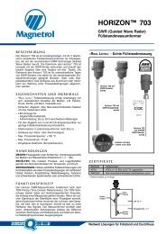
1.1.2 Configuration Information<br />
Units<br />
Sensor Offset<br />
Some key information is needed to configure the R82 radar transmitter. Complete the following<br />
operating parameters table before beginning configuration. Refer to Section 2.4.1.6 for Open Channel<br />
Flow applications.<br />
Display Question Answer<br />
Sensor Offset + Tank Height =<br />
Distance from process<br />
connection to tank bottom<br />
58-610 Model R82 Radar Transmitter<br />
What units of measurement will be used?<br />
Will the unit measure in Level or Volume?<br />
What are the Volume units?<br />
What is the relationship between Level and Volume? (Enter up to 20 points)<br />
What is the distance from the top (100%) of the tank and the Sensor Reference point?<br />
(bottom of NPT thread, top of BSP thread, or face of flange?)<br />
Tank Top Is the Tank Top: Flat, Horizontal Cylinder, Dome, Irregular or Other (non-metallic)?<br />
Tank Height<br />
Blocking Distance<br />
Level Offset<br />
What is the tank height?<br />
NOTE: Sensor Offset + Tank Height = Distance from process connection to tank bottom.<br />
Default of 380 mm (15") is the minimum distance from the process connection to the<br />
maximum level. Extend this value when necessary to block reflections from objects<br />
close to the antenna.<br />
Is there a region at the very bottom of the vessel that cannot be measured due to heating<br />
coils, angle tank bottom, etc.?<br />
Dielectric What is the dielectric of the process medium?<br />
Turbulence Is turbulence a consideration?<br />
Foam Will there be foam on the surface?<br />
Rate of Change What is the maximum rate the level will rise or fall?<br />
4.0 mA Setpoint What is the 0% reference point for the 4.0 mA value?<br />
20.0 mA Setpoint What is the 100% reference point for the 20.0 mA value?<br />
Lowest<br />
Measurable<br />
Value<br />
Level Offset<br />
Highest<br />
Measureable<br />
Value<br />
Sensor Reference Point<br />
Blocking<br />
Distance<br />
Safe Zone<br />
Figure 1<br />
Distance<br />
Media<br />
Level<br />
Tank<br />
Height<br />
Sensor Offset (+)<br />
4 mA<br />
20 mA<br />
5
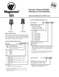
6<br />
Ground<br />
Launcher Adjustment<br />
in #11 Position (Default)<br />
Figure 2<br />
Polarization pattern when launcher<br />
is in the #11 Position (default)<br />
Tangent Line<br />
Figure 3<br />
Polarization shown parallel to tangent<br />
line; either orientation is acceptable<br />
1.2 QuickStart Mounting<br />
1.2.1 Transmitter/Antenna<br />
1. The device is manufactured as one unit that includes the<br />
transmitter and antenna.<br />
2. Remove any protective material from the antenna before<br />
installing.<br />
3. Install the transmitter/antenna into the process connection.<br />
If threaded, tighten securely by hand using the housing for<br />
grip. Ensure there is no cross-threading and do not over<br />
tighten as this may cause damage to the plastic threads.<br />
4. Adjust the beam position by turning the internal launcher<br />
adjustment (Figure 2). The internal launcher adjustment is<br />
numbered 1-18 that equates to 10-180 degrees of adjustment;<br />
9 is the midpoint. The polarization pattern is parallel<br />
to the transmitter display when the adjustment mechanism<br />
is in the #11 position (factory default). Each index number<br />
represents 10 degrees of rotation. After positioning the<br />
transmitter display, the launcher should be adjusted so the<br />
polarization pattern is parallel to a line tangent to the nearest<br />
tank wall (Figure 3). Do not optimize the Echo Strength<br />
at one level in the vessel.<br />
• Do not place insulating material around any part of the<br />
Radar transmitter including the antenna process connection.<br />
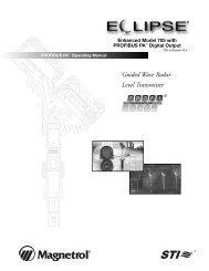
1.3 QuickStart Wiring<br />
NOTE: Make sure the electrical wiring to the R82 radar transmitter is<br />
complete and in compliance with all regulations and codes.<br />
1. Remove the cover of the wiring compartment.<br />
2. Attach a conduit fitting and mount the conduit plug in the<br />
spare opening. Pull the power supply wire through the conduit<br />
fitting.<br />
3. Connect shield to an earth ground at power supply and<br />
leave floating at the transmitter.<br />
4. Connect the positive supply wire to the (+) terminal and the<br />
negative supply wire to the (-) terminal.<br />
5. Seal conduit to prevent ingress of moisture.<br />
6. Replace cover of the transmitter.<br />
58-610 Model R82 Radar Transmitter
(+)<br />
(-)<br />
Ground<br />
Figure 4<br />
Figure 5<br />
58-610 Model R82 Radar Transmitter<br />
Launcher<br />
Adjustment<br />
1.4 QuickStart Configuration<br />
The Radar transmitter comes factory-calibrated and can be<br />
configured in minutes for specific applications. Bench configuration<br />
provides a convenient and efficient way to set up<br />
the transmitter before going to the tank site to complete the<br />
installation. The minimum configuration instructions follow.<br />
Use the information from the operating parameters<br />
table before beginning configuration. See Configuration<br />
Information, Section 1.1.2.<br />
1. Power-up the transmitter.<br />
During normal operation the display changes every 2 seconds<br />
to show one of the various measured values that can be<br />
chosen for display: Level, Volume, Distance, Echo Strength,<br />
%Output, Loop Current and Local Tag.<br />
2. Remove the cover of the electronic compartment.<br />
3. The push buttons offer multiple forms of functionality for<br />
menu navigation and data entry. (See Section 2.6.3 for<br />
complete explanation)<br />
UP arrow moves up through menu or increases<br />
displayed value<br />
DOWN arrow moves down through menu or decreases<br />
displayed value<br />
BACK arrow exits a branch of the menu or exits without<br />
accepting entered value<br />
ENTER arrow enters a branch of the menu or accepts<br />
entered value<br />
If a PASSWORD is requested, enter it now. The Default=0<br />
(no password necessary).<br />
7
1<br />
2<br />
3<br />
4<br />
5<br />
6<br />
7<br />
Measure<br />
Type<br />
Level Units<br />
(select)<br />
Sensor Offset<br />
xxxx<br />
Tank Top<br />
(select)<br />
Tank Height<br />
xxxx<br />
Blocking Dist<br />
xxxx<br />
Level Offset<br />
xxx.x<br />
The following configuration entries are the minimum required for<br />
configuration. The default password is 0 (no password necessary).<br />
Blocking<br />
Distance<br />
7<br />
6<br />
Level<br />
Offset<br />
4<br />
9<br />
Select if Level or Level & Volume<br />
Select the Units of measure for the<br />
display (cm, inches, meters, feet).<br />
Enter the Sensor Offset value; the<br />
distance from the top of the vessel to<br />
the Sensor Reference point (bottom<br />
of an NPT thread, top of a BSP<br />
thread, face of a flange).<br />
Select the type of Tank Top; choices<br />
are Flat, Horizontal cylinder, Dome,<br />
Irregular, or Other (nonmetallic).<br />
Enter the exact Tank Height; inaccurate<br />
values will create inaccurate<br />
level readings.<br />
Enter the Blocking Distance; the<br />
distance close to the antenna where<br />
measurement is unreliable. Minimum<br />
value = 375 mm (15") as measured<br />
from the process connection.<br />
Enter the Level Offset; the distance<br />
at the bottom of the vessel where<br />
measurement may be unreliable due<br />
to heating coils, irregular bottom, etc.<br />
8<br />
10<br />
1<br />
12<br />
Figure 6<br />
11<br />
3<br />
Sensor Offset<br />
14<br />
Tank Height<br />
Dielectric<br />
(select)<br />
Turbulence<br />
(select)<br />
Foam<br />
(select)<br />
Rate of Change<br />
(select)<br />
Echo Profile<br />
Set 4mA<br />
xx.x<br />
Set 20mA<br />
xx.x<br />
Select the proper Dielectric range for<br />
the process medium.<br />
Select the value of Turbulence that<br />
corresponds to the application.<br />
Select the Foam value that corresponds<br />
to the application.<br />
Select the Rate of Change value that<br />
corresponds to the maximum rate the<br />
level will rise or fall.<br />
Examine the list of reflections detected<br />
by the transmitter to ensure the<br />
actual level reflection is present. It<br />
may be necessary to rotate the<br />
launcher for optimal performance.<br />
Run the Echo Rejection routine by<br />
choosing the correct LEVEL thereby<br />
cancelling all false reflections in the<br />
vessel; ideally with tank empty.<br />
Enter the minimum level value (0%)<br />
for the 4 mA point.<br />
Enter the maximum level (100%) for<br />
the 20 mA point.<br />
8 58-610 Model R82 Radar Transmitter<br />
13<br />
8<br />
9<br />
10<br />
11<br />
12<br />
13<br />
14<br />
5<br />
2
58-610 Model R82 Radar Transmitter<br />
2.0 Complete Installation<br />
This section provides detailed procedures for properly<br />
installing, configuring, and, as needed, troubleshooting the<br />
R82 Radar Level Transmitter.<br />
2.1 Unpacking<br />
Unpack the instrument carefully. Make sure all components<br />
have been removed from the packing material. Check all the<br />
contents against the packing slip and report any discrepancies<br />
to the factory.<br />
Before proceeding with the installation, do the following:<br />
• Inspect all components for damage. Report any damage to<br />
the carrier within 24 hours.<br />
• Make sure the nameplate model number on the transmitter<br />
agree with the packing slip and purchase order.<br />
• Record the model and serial numbers for future reference<br />
when ordering parts.<br />
2.2 Electrostatic Discharge (ESD)<br />
Handling Procedure<br />
The MAGNETROL electronic instruments are manufactured<br />
to the highest quality standards. These instruments<br />
use electronic components that may be damaged by static<br />
electricity present in most work environments.<br />
The following steps are recommended to reduce the risk of<br />
component failure due to electrostatic discharge.<br />
• Ship and store circuit boards in anti-static bags. If an antistatic<br />
bag is not available, wrap the board in aluminum foil.<br />
Do not place boards on foam packing materials.<br />
• Use a grounding wrist strap when installing and removing<br />
circuit boards. A grounded workstation is recommended.<br />
• Handle circuit boards only by the edges. Do not touch<br />
components or connector pins.<br />
• Make sure that all electrical connections are completely<br />
made and none are partial or floating. Ground all equipment<br />
to a good, earth ground.<br />
9
MAXIMUM DISTANCE meters (feet)<br />
Sensor Offset<br />
+ Tank Height =<br />
Distance from<br />
process connection<br />
to tank bottom<br />
Lowest<br />
Measurable<br />
Value<br />
10<br />
Dielectric Turbulence R82<br />
1.7-3.0<br />
3.0-10.0<br />
10.0-100<br />
Level Offset<br />
None<br />
Light, < 0.5"<br />
Moderate, < 1.0"<br />
Heavy, > 1.0"<br />
None<br />
Light, < 0.5"<br />
Moderate, < 1.0"<br />
Heavy, > 1.0"<br />
None<br />
Light, < 0.5"<br />
Moderate, < 1.0"<br />
Heavy, > 1.0"<br />
Highest<br />
Measureable<br />
Value<br />
Figure 7<br />
Sensor Reference Point<br />
Blocking<br />
Distance<br />
Safe Zone<br />
Distance<br />
Media<br />
Level<br />
7.9 (26)<br />
6.4 (21)<br />
4.3 (14)<br />
2.1 (7)<br />
10.1 (33)<br />
7.9 (26)<br />
5.8 (19)<br />
3.7 (12)<br />
12 (40)<br />
9.8 (32)<br />
7.3 (24)<br />
5.2 (17)<br />
2.3 Before You Begin<br />
Tank<br />
Height<br />
2.3.1 Site Preparation<br />
Each R82 Radar transmitter is built to match the physical<br />
specifications of the required installation. Make sure the<br />
antenna connection is correct for the threaded or flanged<br />
mounting on the vessel or tank where the transmitter will<br />
be placed. See Mounting, Section 2.4.<br />
Make sure that the wiring between the power supply and<br />
Radar transmitter are complete and correct for the type<br />
of installation.<br />
When installing the Radar transmitter in a general purpose<br />
or hazardous area, all local, state, and federal regulations and<br />
guidelines must be observed. See Wiring, Section 2.5.<br />
2.3.2 Equipment and Tools<br />
No special tools are needed. The following items<br />
are recommended:<br />
• Threaded antenna and transmitter . . . . . . 50 mm (2")<br />
• Flat-blade screwdriver<br />
• Digital multimeter or volt/ammeter . . . . . Optional<br />
• 24 VDC (23 mA) power supply. . . . . . . . Optional<br />
2.3.3 Operational Considerations<br />
Radar applications are characterized by three basic conditions;<br />
Dielectric, Distance (measuring range) and Disturbances<br />
(turbulence, foam, false targets, multiple reflections and rate<br />
of change).<br />
Sensor Offset (+)<br />
4 mA<br />
20 mA<br />
2.3.3.1 Maximum Distance<br />
Figure 7 at left shows the maximum measuring range<br />
(Distance) based on fundamental conditions of<br />
Dielectric, Distance and Turbulence. Maximum distance<br />
is calculated as Tank Height + Sensor Offset. It<br />
is measured from the Sensor Reference Point (bottom<br />
of NPT thread, top of BSP thread or face of a flange).<br />
2.3.3.2 Minimum Distance<br />
If the liquid level is allowed onto the antenna, noise<br />
and media build-up drastically decrease reliable measurement.<br />
Liquid should not be allowed closer than<br />
380 mm (15"), BSP: 405 mm (16") from the bottom<br />
of the antenna mounting threads (or face of hygienic<br />
flange). The distance from the end of the antenna<br />
varies depending on antenna chosen. See Figure 8.<br />
58-610 Model R82 Radar Transmitter
380 mm (15"),<br />
BSP: 405 mm (16")<br />
minimum<br />
(measured from bottom<br />
of threads or flange<br />
58-610 Model R82 Radar Transmitter<br />
50 mm (2") Antenna<br />
330 mm<br />
(13")<br />
50 mm (2")<br />
Figure 8<br />
Minimum distance to end of antenna varies<br />
depending on antenna used<br />
100 mm (4")<br />
m<br />
d d<br />
380 mm (15")<br />
BSP: 405 mm (16")<br />
230 mm (9")<br />
Maximum<br />
liquid level<br />
200 mm (8") Antenna<br />
face) 178 mm<br />
(7")<br />
Maximum recess (m) is 2 x nozzle diameter (d) (schedule 40 maximum)<br />
(example: 2" diameter nozzle)<br />
50 mm (2") Antenna<br />
200 mm (8") Antenna<br />
205 mm (8")<br />
100 mm (4")<br />
75 mm (3")<br />
Maximum<br />
liquid level<br />
Figure 9<br />
Using nozzle height to maximize useable tank space<br />
380 mm (15")<br />
BSP: 405 mm (16")<br />
2.3.3.3 Problematic Applications; GWR Alternative<br />
Some application concerns can be problematic for Radar.<br />
For these, Guided Wave Radar is recommended:<br />
• Extremely low dielectric media (ε r
25 cm<br />
(10")<br />
1/2<br />
Radius<br />
Figure 10<br />
W<br />
Distance Beam Spread<br />
Meters Feet Meters Feet<br />
3 10 0.74 2.5<br />
6 20 1.47 4.9<br />
9 30 2.21 7.4<br />
12 40 2.95 9.8<br />
Figure 11<br />
• Foam can either absorb or reflect the microwave energy<br />
depending upon the depth, dielectric, density and wall<br />
thickness of the bubbles. Due to typical variations in the<br />
amount (depth) of foam, it is impossible to quantify performance.<br />
It may be possible to receive most, some or<br />
none of the transmitted energy.<br />
• Extremely high liquid levels (Overflow) conditions when<br />
liquid very near the antenna (above the Blocking Distance)<br />
can cause erroneous readings and measurement failure.<br />
2.4 Mounting<br />
The R82 Radar transmitter can be mounted to a vessel<br />
using a variety of process connections. Generally, either a<br />
threaded or flanged connection is used.<br />
2.4.1 Installing the Transmitter<br />
Before installing, make sure:<br />
• Process temperature, pressure, dielectric, turbulence and<br />
distance are within the antenna specifications for the<br />
installation.<br />
• End of antenna is protected from bending or breaking.<br />
• Insulating material is not placed around any part of the<br />
Radar transmitter including the antenna flange.<br />
• Transmitter is being mounted in the optimal location. See<br />
following sections: Location, Beam Angle, Obstructions,<br />
Nozzles, Stillwells, and Open Channel Flow for specific<br />
information.<br />
2.4.1.1 Location<br />
Ideally, the Radar transmitter should be mounted providing<br />
an unobstructed signal path to the liquid surface where<br />
it should illuminate (with microwave energy) the largest,<br />
possible surface area. See Section 2.4.1.2, Beam Angle.<br />
Unavoidable obstacles will produce reflections that must<br />
be minimized during field configuration. Mount in a<br />
location equal to 1 ⁄2 the radius of tank top. Do not mount<br />
in center of vessel nor closer than 25 cm (10") from the<br />
tank wall.<br />
2.4.1.2 Beam Angle<br />
Ideally, the beam pattern should illuminate the maximum<br />
liquid surface with a minimum striking other objects in<br />
the vessel including the tank wall.<br />
12 58-610 Model R82 Radar Transmitter
Figure 12<br />
Avoiding Obstructions<br />
50 mm (2")<br />
58-610 Model R82 Radar Transmitter<br />
2.4.1.3 Obstructions<br />
Almost any object that falls within the beam pattern will<br />
cause reflections that may be misinterpreted as a false liquid<br />
level. Although Model R82 has a powerful Echo Rejection<br />
routine, all possible precautions should be taken to minimize<br />
false target reflections with proper installation and<br />
orientation. See Figure 12.<br />
2.4.1.4 Nozzles<br />
100 mm (4")<br />
m<br />
d d<br />
Improper installation in a nozzle creates “ringing” which<br />
will adversely affect measurement. Two Antenna extension<br />
lengths are offered to allow the R82 transmitter to work<br />
reliably in a variety of nozzles.<br />
The Minimum Blocking Distance of 380 mm (15") is<br />
always measured from the bottom of the threads or face of<br />
the flange. The related distance as measured from the end of<br />
the antenna varies depending on the antenna extension<br />
chosen. See Figure 13.<br />
The narrow beam width of the 26 GHz, R82 does allow<br />
mounting so that the antenna can be recessed inside the<br />
nozzle. Optimally, the recessed dimension should never<br />
exceed 2× the nozzle diameter (Schedule 40 maximum).<br />
See Figure 13.<br />
NOTE: If the antenna is recessed in a nozzle it is mandatory that Echo<br />
Rejection is run to eliminate any possibility of false reflections.<br />
Maximum recess (m) is 2 x nozzle diameter (d) (schedule 40 maximum)<br />
(example: 2" diameter nozzle)<br />
50 mm (2") Antenna<br />
380 mm (15")<br />
BSP: 405 mm (16")<br />
230 mm (9")<br />
Maximum<br />
liquid level<br />
200 mm (8") Antenna<br />
205 mm (8")<br />
100 mm (4")<br />
75 mm (3")<br />
Maximum<br />
liquid level<br />
Figure 13<br />
Using nozzle height to maximize useable tank space<br />
380 mm (15")<br />
BSP: 405 mm (16")<br />
13
Figure 14<br />
R82 Mounted in Stillwell (Bridle)<br />
Parshall<br />
Flume<br />
Figure 15<br />
Open Channel Flow Mounting<br />
NOTE:<br />
Proper position of the Model R82<br />
should be per the recommendation of<br />
the flume or weir manufacturer and<br />
meeting minimum height recommendations.<br />
Mounting at least 75 cm (30")<br />
above the top of the element will yield<br />
best accuracy.<br />
Model R82<br />
2.4.1.5 Stillwells<br />
The R82 can be mounted in a stillwell but certain considerations<br />
should be given:<br />
• Metal stillwells only: 50 mm (2") Sched 40 max.<br />
• Diameter must be consistent throughout length; no reducers.<br />
• Stillwell length must cover complete range of measurement<br />
(i.e., liquid must be in stillwell).<br />
• Welds should be smooth.<br />
• Vents: holes < 3 mm (0.125") diameter, slots < 3 mm<br />
(0.125") width.<br />
• If an isolation valve is used, it must be a full port ball valve<br />
with an I.D. equal to the pipe diameter.<br />
• Bridles/Bypass Installations: The launcher should be rotated<br />
90° from process connections.<br />
• Configuration must include an entry for Stillwell I.D.<br />
See Section 2.6.6.2, Item 34- Stillwell I.D.<br />
2.4.1.6 Open Channel Flow Measurement<br />
For optimal accuracy, mount the transmitter a minimum of<br />
75 cm (30") above the flow element (this is dependent on<br />
type and size of the flow element). Consult factory for assistance<br />
on this dimension.<br />
Flow<br />
Install the Model R82 on the inflow side of the flume throat<br />
or weir crest in the location defined by the manufacturer of<br />
the primary measuring device. The unit should also be<br />
aligned with the longitudinal axis of the flume or weir.<br />
Open channel flow is performed by using the R82 to measure<br />
the level (Head) in a hydraulic structure. The hydraulic<br />
structure is the primary measuring element, of which the<br />
two most common types are weirs and flumes. Since the<br />
primary element has a defined shape and dimensions, the<br />
rate of flow through the flume or over the weir is related to<br />
the liquid level (Head) at a specified measurement location.<br />
The Model R82 is the secondary measuring device which<br />
measures the height (Head) of the liquid in the flume or<br />
weir. Open channel flow equations stored in the R82<br />
firmware convert the measured Head into units of flow<br />
(volume/time).<br />
14 58-610 Model R82 Radar Transmitter
Ground<br />
Launcher Adjustment<br />
in #11 Position (Default)<br />
Figure 16<br />
Launcher Adjustment in<br />
#11 Position (default)<br />
Tangent Line<br />
Figure 17<br />
Polarization Pattern<br />
30 degrees: Rotate Launcher<br />
Mechanism Clockwise (CW) 3 notches<br />
Tangent Line<br />
∠30°<br />
90 degrees: Rotate Launcher<br />
Mechanism CW 9 notches<br />
∠90°<br />
Figure 18<br />
Examples of Launcher<br />
Orientation Adjustments<br />
58-610 Model R82 Radar Transmitter<br />
2.4.2 Installing the Transmitter<br />
Install the Transmitter with its integral antenna by threading<br />
into the vessel. DO NOT OVERTIGHTEN as this may<br />
cause damage to the plastic threads.<br />
• Do not place insulating material around any part of the<br />
radar transmitter including the antenna flange.<br />
2.4.2.1 Orientation<br />
The R82 transmitter utilizes a linearly polarized, microwave<br />
beam that can be rotated to improve its performance.<br />
Proper orientation can minimize unwanted reflections,<br />
decrease sidewall reflections (multipath) and maximize<br />
direct reflections from the liquid surface.<br />
The internal launcher mechanism can be turned to optimize<br />
performance. The launcher has index marks numbered<br />
1–18 (representing 10–180 degrees). The polarization<br />
pattern is parallel to the transmitter display when the<br />
adjustment mechanism is in the #11 position (factory<br />
default). Each index number represents 10 degrees of rotation.<br />
See Figures 16 and 17.<br />
2.4.2.2 Launcher Orientation—Level Application<br />
Ideally, the transmitter should be mounted half the radius<br />
from the tank wall. In a typical vertical tank, the Launcher<br />
should be adjusted so the polarization pattern is parallel to a<br />
line tangent to the nearest tank wall. See Figure 17.<br />
Rotate the internal Launcher adjustment to achieve the<br />
correct Polarization position. Remember each notch on the<br />
adjustment wheel is 10 degrees of rotation. See Figure 18.<br />
For horizontal cylindrical vessels, aim beam down the long<br />
axis of the vessel. Do not optimize the Echo Strength at one<br />
level in the vessel.<br />
A transmitter mounted within 25 cm (10") of a tank wall<br />
may demand orientation adjustments to limit multipath<br />
and optimize performance. See Section 2.4.2.4,<br />
Poor Echo Strength.<br />
15
16<br />
(+)<br />
(-)<br />
Ground<br />
Figure 19<br />
Internal Launcher Adjustment<br />
Figure 20<br />
Mounting Over Flume<br />
Launcher<br />
Adjustment<br />
2.4.2.3 Launcher Orientation — Flow Application<br />
Orient the R82 transmitter so the Polarization pattern is<br />
aimed directly down the throat of the flume or weir.<br />
If conduit connections are oriented 90° to the flow, set the<br />
Launcher Adjustment to #2.<br />
2.4.2.4 Poor Echo Strength<br />
Poor Echo Strength has many potential causes. Following<br />
are two initial areas for investigation.<br />
Launcher Orientation: Initial launcher orientation is always<br />
parallel to tangent of the tank circumference (see Sections<br />
2.4.2.1 & 2.4.2.2). In tall vessels and when antenna is<br />
mounted close to the tank wall, improvement in Echo<br />
Strength may be attained by rotating the launcher to<br />
90 degrees.<br />
Signal Loss: If the Level signal is lost repeatedly at a specific<br />
point in the vessel, it is usually a symptom that multipath<br />
(side-wall reflections) are causing cancellation by returning<br />
to the transmitter exactly 180° out of phase with the Level<br />
signal. Utilize the following procedure:<br />
• Go to transmitter screen #5 which shows both Level and<br />
Echo Strength.<br />
• Bring the Level up (or down) to the exact point where the<br />
signal is repeatedly lost. Monitor the Echo Strength this<br />
point is being approached. The Echo Strength will degrade<br />
to a low point before it begins to increase.<br />
• At the poorest Echo Strength slowly rotate the launcher<br />
1–2 notches. Allow the unit to stabilize for approximately<br />
one minute. Repeat this process until the Echo Strength<br />
is optimized.<br />
58-610 Model R82 Radar Transmitter
(+)<br />
(-)<br />
Ground<br />
Figure 21<br />
Wiring the Transmitter<br />
Caution: The R82 Radar transmitter<br />
operates at voltages of 16–36 VDC (GP)<br />
and 16-28.6 VDC (IS). Higher voltage will<br />
damage the transmitter.<br />
NOTES:<br />
• If sufficient supply voltage is suspect,<br />
use the R82 Low Voltage check<br />
(Section 2.6.6.1, #33: Test 4-20 Loop).<br />
58-610 Model R82 Radar Transmitter<br />
2.5 Wiring<br />
Wiring between the power supply and the Radar transmitter<br />
should be made using 18–22 AWG shielded twisted pair<br />
instrument cable. Within the transmitter enclosure, connections<br />
are made to the terminal strip and the ground connections.<br />
Trim excess wiring to minimize clutter, noise issues and<br />
allow access to Launcher adjustment. See Figure 21. The<br />
directions for wiring the Radar transmitter depend on the<br />
application:<br />
• General Purpose or Non-incendive (Cl I, Div. 2)<br />
• Intrinsically Safe<br />
2.5.1 General Purpose or Non-incendive (Cl I, Div. 2)<br />
A general purpose installation does not have flammable<br />
media present. Areas rated non-incendive (Cl I, Div. 2) have<br />
flammable media present only under abnormal conditions.<br />
No special electrical connections are required. If flammable<br />
media is contained in the vessel, the transmitter must be<br />
installed per Cl I, Div. 1 standards of area classification.<br />
To install General Purpose or Non-incendive wiring:<br />
1. Remove the cover to the wiring compartment of the transmitter.<br />
Install the conduit plug in the unused opening.<br />
2. Install a conduit fitting and pull the supply wires.<br />
3. Connect shield to an earth ground at power supply and<br />
leave floating at the transmitter.<br />
4. Connect an earth ground wire to the nearest green ground<br />
screw per local electrical code (not shown in illustration).<br />
5. Connect the positive supply wire to the (+) terminal and the<br />
negative supply wire to the (-) terminal.<br />
6. Seal conduit to prevent ingress of moisture.<br />
7. Replace cover of the transmiter.<br />
2.5.2 Intrinsically Safe<br />
An intrinsically safe (IS) installation potentially has flammable<br />
media present. An approved IS barrier must be installed<br />
in the non-hazardous (safe) area.<br />
To install Intrinsically Safe wiring:<br />
1. Make sure the IS barrier is properly installed in the safe area<br />
(refer to local plant or facility procedures). Complete the<br />
wiring from the barrier to the Radar transmitter.<br />
2. Remove the cover of the transmitter. Install the conduit<br />
plug in the unused opening.<br />
3. Install a conduit fitting and pull the supply wires.<br />
4. Connect shield to an earth ground at power supply and<br />
leave floating at the transmitter.<br />
17
(+)<br />
(-)<br />
18<br />
Ground<br />
Figure 22<br />
Display and Keypad<br />
Launcher<br />
Adjustment<br />
5. Connect an earth ground wire to the nearest green ground<br />
screw (not shown in illustration).<br />
6. Connect the positive supply wire to the (+) terminal and the<br />
negative supply wire to the (-) terminal.<br />
7. Replace the cover of the transmitter.<br />
2.6 Configuring the Transmitter<br />
The Radar transmitter comes factory-calibrated and can be<br />
configured in minutes for specific applications.<br />
Before configuring the transmitter, collect the operating<br />
parameters information. Then, power-up the transmitter on<br />
the bench and follow through the step-by-step procedures<br />
for the menu-driven transmitter display. Information on<br />
configuring the transmitter using a HART communicator is<br />
given in Configuration Using HART (Section 2.7).<br />
2.6.1 Operating Parameters<br />
Some key information is needed to configure the Radar<br />
transmitter. If necessary, complete the configuration information<br />
table in Section 1.1.2.<br />
2.6.2 Setting Up for Shop Configuration<br />
The Radar transmitter can be configured at a test bench by<br />
connecting a 24 VDC power supply directly to the transmitter<br />
terminals. The connections are illustrated in the<br />
accompanying diagrams. An optional digital multimeter is<br />
shown if current measurements are desired.<br />
When using a HART communicator for configuration, a<br />
minimum 250 Ω line load resistance is required. See the<br />
HART communicator manual for more information.<br />
2.6.3 Transmitter Display and Keypad<br />
The R82 transmitter has a local user interface consisting of<br />
a 2-line × 16-character liquid-crystal display (LCD) and<br />
4-push-button keypad. All transmitter measurement data<br />
and configuration information is shown in the LCD.<br />
The transmitter default display is the measurement screen.<br />
It cycles every 2 seconds to display *STATUS*, *LEVEL*,<br />
*ECHO STRENGTH*, *%OUTPUT*, *LOOP CUR-<br />
RENT* and *LOCAL TAG* information. The transmitter<br />
defaults to this display after 5 minutes if no keystrokes are<br />
sensed. You can also access each of these screens individually.<br />
The display will not return to the default screen if left in<br />
one of these screens. For example, the device can be left to<br />
display only LEVEL indefinitely if left in this screen.<br />
58-610 Model R82 Radar Transmitter
Figure 23<br />
Figure 24<br />
NOTES: All numeric values are left-justified, and<br />
new values are entered from left to right. A decimal<br />
point can be entered after the first digit is<br />
entered, such that .9 is entered as 0.9.<br />
Some configuration items can have a negative<br />
value. In this case, the leftmost position is<br />
reversed for the sign (either “-” for a negative<br />
value, or “+” for a postive value).<br />
58-610 Model R82 Radar Transmitter<br />
2.6.4 Menu Traversal and Data Entry<br />
The four push buttons offer various forms of functionality<br />
for navigation and data entry (i.e., Navigation, Data<br />
Selection, etc.).<br />
2.6.4.1 Navigating Menu<br />
Push button Keystroke Action<br />
Up Moves to the previous item in the menu branch<br />
Down Moves to the next item in the menu branch<br />
Back<br />
Enter<br />
2.6.4.2 Data Selection<br />
Moves back one level to the previous higher<br />
branch item<br />
Enters into the lower level branch or switches to<br />
the entry mode<br />
Use this method for selecting configuration data from a<br />
specific list. An arrow will appear when in the Data<br />
Selection mode. See Figure 23.<br />
Use the following procedure:<br />
• UP an DOWN arrows to navigate the main menu<br />
• ENTER arrow to allow modification of selection<br />
• UP an DOWN arrows to choose new selection<br />
• ENTER arrow to confirm selection<br />
• Use BACK (Escape) key at any time to abort the procedure<br />
and escape to previous branch item.<br />
2.6.4.3 Entering Numeric Data Using Digit Entry<br />
Use this method to input numeric data, e.g.,<br />
Sensor Offset.<br />
Push button Keystroke Action<br />
Up<br />
Down<br />
Back<br />
Enter<br />
Moves up to the next highest digit (0,1,2,3,....,9).<br />
If held down the digits scroll until the push button<br />
is released.<br />
Moves down to the next lowest digit<br />
(9,8,7,6,….,0). If held down the digits scroll until<br />
the push button is released.<br />
Moves the cursor to the left and deletes a digit. If<br />
the cursor is already at the leftmost position,<br />
then the screen is exited without changing the<br />
previously saved value.<br />
Moves the cursor to the right. If the cursor is<br />
located at a blank character position, the new<br />
value is saved.<br />
19
Figure 25<br />
Figure 26<br />
2.6.4.4 Entering Numeric Data Using Increment/Decrement<br />
Use this method to input the following data: Damping,<br />
Echo Loss Delay, Trim Level, Trim 4 mA, Trim 20 mA,<br />
Test 4-20 Loop and HART Poll Addr.<br />
Push button Keystroke Action<br />
2.6.4.5 Entering Character Data<br />
This method is used for entering alphanumeric characters,<br />
e.g., Input Local Tag.<br />
Push button Keystroke Action<br />
20 58-610 Model R82 Radar Transmitter<br />
Up<br />
Down<br />
Back<br />
Enter<br />
Up<br />
Down<br />
Back<br />
Enter<br />
Increments the displayed value. If held down the<br />
digits scroll until the push button is released.<br />
Depending on which screen is being revised, the<br />
increment amount may increase by a factor of 10<br />
after the value has been incremented 10 times.<br />
Decrements the displayed value. If held down the<br />
digits scroll until the push button is released.<br />
Depending on which screen is being revised, the<br />
decrement amount may increase by a factor of 10<br />
after the value has been decremented 10 times.<br />
Returns to the previous menu without changing<br />
the original value, which is immediately redisplayed.<br />
Accepts the displayed value and returns to the<br />
previous menu.<br />
Moves to the previous character (Z,Y,X,W). If held<br />
down the characters scroll until the push button<br />
is released.<br />
Moves to the next item character (A,B,C,D). If<br />
held down the characters scroll until the push<br />
button is released.<br />
Moves the cursor back to the left. If the cursor<br />
is already at the leftmost position, then the<br />
screen is exited without changing the original<br />
tag characters.<br />
Moves the cursor forward to the right. If the<br />
cursor is at the rightmost position, then the<br />
new tag is saved.
Sensor Offset<br />
+ Tank Height =<br />
Distance from<br />
process connection<br />
to tank bottom<br />
Lowest<br />
Measurable<br />
Value<br />
Level Offset<br />
Highest<br />
Measureable<br />
Value<br />
58-610 Model R82 Radar Transmitter<br />
Sensor Reference Point<br />
Blocking<br />
Distance<br />
Safe Zone<br />
Figure 27<br />
Distance<br />
Media<br />
Level<br />
2.6.5 Password Protection (Default = 0)<br />
The Radar transmitter is password protected to restrict<br />
access to certain portions of the menu structure that affect<br />
the operation of the system. The password can be changed<br />
to any numerical value up to 255. The password is required<br />
whenever configuration values are changed.<br />
The default password installed in the transmitter at the<br />
factory is 0 (password disabled). The last step in the configuration<br />
menu provides the option to enter a new password.<br />
If 0 is entered as a password, the transmitter is no longer<br />
password protected and any value in the menu can be<br />
altered (except diagnostic values) without entering a confirming<br />
password.<br />
NOTE: If the password is not known, the menu item New Password<br />
(Section 2.6.6.1 Level Measurement Only, item #35; Section<br />
2.6.6.2 Volume and Level, item #39; Section 2.6.6.3 Flow and<br />
Level, item #41) displays an encrypted value representing the<br />
present password. Call the factory with this encrypted value to<br />
determine the actual password.<br />
2.6.6 Menu: Step-By-Step Procedure<br />
The following tables provide a complete explanation of the<br />
software menus displayed by the Radar transmitter. Use these<br />
tables as a step-by-step guide to configure the transmitter.<br />
The first column presents the menus shown on the transmitter<br />
display. The displays are in the order they would<br />
appear if the arrow keys were used to scroll through the<br />
menu. The numbers are not shown<br />
on the display. They are provided as a<br />
Sensor Offset (+) reference only.<br />
20 mA The second column provides the<br />
actions to take when configuring the<br />
transmitter. Additional information or<br />
an explanation of an action is given in<br />
the third column.<br />
Tank<br />
Height<br />
4 mA<br />
Figure 27 provides reference to the<br />
configuration procedure.<br />
Use of the included PACTware PC<br />
program is highly recommended and<br />
invaluable for troubleshooting and<br />
advanced calibration. A HART RS232<br />
or USB modem (purchased separately)<br />
is required. See MAGNETROL<br />
PACTware bulletin 59-101.<br />
21
2.6.6.1 Radar Transmitter User Menu—Level Measurement Only<br />
Note: Press UP arrow 5 times to reach screen where menu language can be chosen.<br />
1<br />
2<br />
3<br />
4<br />
5<br />
6<br />
7<br />
8<br />
9<br />
10<br />
11<br />
12<br />
Display Action Comment<br />
*Status*<br />
*Level*<br />
*Volume*<br />
*Distance*<br />
*Echo Str xx*<br />
*%Output*<br />
*Loop Current*<br />
*Local Tag*<br />
Level<br />
xxx.x units<br />
Distance<br />
xxx.x units<br />
Echo Strength xx<br />
xxx.x units<br />
% Output<br />
xx.x%<br />
Loop Current<br />
xx.xx mA<br />
Local Tag<br />
xxxxxxxxxxxx<br />
Measure Type<br />
(select)<br />
Level Units<br />
(select)<br />
Sensor Offset<br />
xx.x units<br />
Tank Top<br />
(select)<br />
Tank Height<br />
xxx.xx units<br />
Transmitter Display<br />
Transmitter Display<br />
Transmitter Display<br />
Transmitter Display<br />
Transmitter Display<br />
Transmitter Display<br />
Transmitter Display<br />
Select Type of Measurement<br />
Select Units of measure<br />
Enter the Sensor Offset value<br />
Enter the shape/type<br />
of tank top<br />
Enter the Tank Height<br />
Transmitter default display: Status, Level, Distance,<br />
Echo Strength, % Output, Loop Current and Local Tag values<br />
advance every 2 seconds. All screens (except 2-8) default to this<br />
screen after 5 minutes of no keystrokes or if a Fault or Warning<br />
message is displayed.<br />
Default display will also show the highest priority Fault or<br />
Warning. If more than one Fault or Warning exists they will be<br />
displayed in the History screen (Item #2, Section 2.6.6.4 Radar<br />
Transmtter Factory Menu on Page 40) in chronological order.<br />
To Add/Remove what information is shown in default display:<br />
• Go to specific parameter in question (screens 2-8)<br />
• Press Enter<br />
• Choose On or Off<br />
• Press Enter to confirm<br />
Transmitter displays Level measurement in chosen unit of<br />
measure.<br />
Transmitter displays Distance measurement in chosen unit of<br />
measure; measurement includes Sensor Offset value. This value<br />
may not represent reciprocal of Level if the liquid level is<br />
within the Blocking Distance or Level Offset where the Level<br />
value is clamped.<br />
Transmitter display showing Level and Echo Strength of signal<br />
reflection. Good values are 20-99.<br />
Transmitter displays % Output measurement derived from<br />
20 mA span.<br />
Transmitter displays Loop Current value (mA).<br />
Transmitter displays Local Tag information.<br />
Select Level Only or Flow & Level, Volume & Level, Flow,<br />
Flow Units, Volume, Volume Units, Loop Control, and<br />
Strapping Table screens appear when necessary. Note that<br />
the Flow or Volume screens are selected for rotation when<br />
Measure Type is set to Flow & Level or Volume & Level and is<br />
deselected when Measure Type is set to Level Only.<br />
See Section 2.6.6.2 for the complete Volume and Level menu or<br />
2.6.6.3 for the complete Flow and Level menu.<br />
Select cm (xxxx), meters (xx.xx), inches (xxx.x), or feet (xx.xx).<br />
Allowable decimal position is controlled; four characters is<br />
maximum reading. Decimal position is controlled by Units<br />
and Tank Height.<br />
Sensor Offset is the distance (+ or -) from the Sensor reference<br />
point (bottom of NPT thread or flange face, top of BSP thread)<br />
to the top of the tank.<br />
Select the metallic tank top structure Flat, Horizontal Cylinder,<br />
Dome, Irregular, or Other (non-metallic).<br />
Tank Height is distance from the bottom to the top of the tank.<br />
22 58-610 Model R82 Radar Transmitter
2.6.6.1 Radar Transmitter User Menu—Level Measurement Only (cont.)<br />
Note: Press UP arrow 5 times to reach screen where menu language can be chosen.<br />
13<br />
14<br />
15<br />
16<br />
17<br />
18<br />
Display Action Comment<br />
Blocking Distance<br />
(xxx.x)<br />
Level Offset<br />
(xxx.x units)<br />
Dielectric<br />
(select)<br />
Turbulence<br />
(select)<br />
Foam<br />
(select)<br />
Rate of Change<br />
(select)<br />
19 Echo Profile<br />
58-610 Model R82 Radar Transmitter<br />
Enter the Blocking Distance<br />
Enter the Level Offset<br />
Enter the Dielectric range value<br />
Select amount of<br />
Turbulence of the liquid<br />
Select amount of Foam<br />
Select Rate of Change of the liquid<br />
Press Enter to<br />
- Review all Echoes<br />
- Run a new Echo Rejection Profile<br />
Blocking Distance defines an area near the antenna<br />
where reflections can not be measured effectively due<br />
to antenna ringing. It is measured from the Sensor<br />
Reference point. Default of 380 mm (15") minimum distance<br />
from the process connection to the maximum level.<br />
Extend this value when necessary to block reflections<br />
from objects close to the antenna. Output will be held<br />
at value corresponding to Blocking Distance. Do not<br />
allow liquid into the Blocking Distance as false readings<br />
can result.<br />
Level Offset defines an area at the bottom of the vessel<br />
where reflections can not be measured effectively due to<br />
angled bottoms, heating coils, reflections from flat metal<br />
tank bottoms in low dielectric applications, etc. It is the<br />
distance from the bottom of the tank to the lowest valid<br />
level reading. Level reading will never be lower than<br />
Level Offset value.<br />
1.7-3.0; 3.0-10.0; 10.0-100.0<br />
None, Light, Medium, Heavy. Increase selection if Echo<br />
is often lost or Echo Strength is
2.6.6.1 Radar Transmitter User Menu—Level Measurement Only (cont.)<br />
Note: Press UP arrow 5 times to reach screen where menu language can be chosen.<br />
19<br />
20<br />
21<br />
22<br />
23<br />
24<br />
25<br />
26<br />
27<br />
28<br />
29<br />
30<br />
Display Action Comment<br />
Echo Profile<br />
(cont.)<br />
4 mA Set Point<br />
(xxx.x units)<br />
20 mA Set Point<br />
(xxx.x units)<br />
Damping<br />
(xx sec)<br />
- Review an existing Echo<br />
Rejection Profile<br />
Enter the value for the<br />
4 mA point<br />
Enter the value for the<br />
20 mA point<br />
Enter the Damping factor<br />
System Fault<br />
(select) Select the System Fault value<br />
Echo Loss Fault<br />
(select)<br />
Echo Loss Delay<br />
(xxx sec)<br />
Safe Zone Fault<br />
(select)<br />
Safe Zone Height<br />
(xx.x units)<br />
Safe Zone Alarm<br />
(Reset)<br />
Trim Level<br />
(xxx.x units)<br />
Stillwell I.D.<br />
(xx.x units)<br />
Select the Echo Loss<br />
Fault value<br />
Enter the value for the Echo<br />
Loss Delay<br />
Select the Safe Zone Fault<br />
Enter a Safe Zone Distance<br />
Clear Safe Zone Alarm<br />
Enter a Trim Level value<br />
Enter Pipe I.D.<br />
31 Trim 4 mA Fine tune the 4mA point<br />
continued from previous page<br />
4.) Enter Level- use this entry to manually enter the<br />
correct level value<br />
Error messages:<br />
“Echo too Close” indicates the liquid is too close to the<br />
antenna. Liquid should not be closer than 750 mm (30").<br />
“Echo too Strong” indicates an echo being rejected is<br />
too strong.<br />
a.) Ensure it is not the actual liquid level<br />
b.) Rotate the Launcher to minimize the echo<br />
5.) Saved Echo Rejection Profilea.)<br />
Enable or Disable an existing profile<br />
b.) Review Echoes from an existing profile<br />
c.) Review Level value where existing profile was run<br />
During normal operation, mA value will clamp at boundary<br />
defined by the Level Offset value (refer to #14).<br />
During normal operation, mA value will clamp at boundary<br />
defined by the Blocking Distance value (refer to #13).<br />
A damping factor (0-45) may be added to smooth a noisy<br />
display and/or output due to turbulence.<br />
Select 3.6 mA, 22 mA or HOLD (last value).<br />
Select 3.6 mA, 22 mA or HOLD (last value).<br />
Select a value 0-1000; 30 is default.<br />
Safe Zone is a user-defined area just below the Blocking<br />
Distance. Set this Fault if it necessary to ensure safe, reliable<br />
high-level readings in critical applications. Choices are None,<br />
3.6 mA, 22 mA, Latch 3.6 or Latch 22. If Latch 3.6 or Latch 22 is<br />
chosen, the loop current will remain in alarm until it it cleared by<br />
customer in SZ Alarm below (refer to #28)<br />
Enter a distance value that develops a zone just below the<br />
Blocking Distance. At this point the unit will report a Safety<br />
Zone Fault (refer to #26) if the level rises into this area.<br />
Clear a latched Safe Zone alarm.<br />
Trim Level is an offset value to be used to force the transmitter<br />
to output the proper Level. This should only be used after Tank<br />
Height and Sensor Offset have been confirmed as correct.<br />
-61 to +61 cm (-24 to +24 inches).<br />
For measuring in a stillwell. Enter a value for inside diameter<br />
of the pipe (presently only 50 mm (2") is acceptable). Range<br />
of values 0, 40-500 mm (0, 3-20 inches). Value must be left as 0<br />
if no standpipe/stillwell is present.<br />
Attach a mA meter to the output. If the output does not equal<br />
4.00 mA, adjust the value on the display until meter reads<br />
4.00 mA. This is not for setting the 4mA point (refer to #20).<br />
24 58-610 Model R82 Radar Transmitter
2.6.6.1 Radar Transmitter User Menu—Level Measurement Only (cont.)<br />
Note: Press UP arrow 5 times to reach screen where menu language can be chosen.<br />
Display Action Comment<br />
32 Trim 20 mA Fine tune the 20mA point<br />
33<br />
34<br />
35<br />
36<br />
37<br />
38<br />
Test 4–20 Loop<br />
(xx.xx mA)<br />
Hart Poll Addr<br />
(xx)<br />
New Password<br />
(enter)<br />
Configuration<br />
Reset<br />
Language<br />
(select)<br />
Input Local Tag<br />
(enter)<br />
58-610 Model R82 Radar Transmitter<br />
Enter a mA Output value<br />
Select HART Poll Address<br />
number<br />
Enter new Password<br />
Enter to Reset Parameters<br />
Select Language<br />
Enter Local Tag<br />
39 <strong>Magnetrol</strong> S/N Transmitter Display<br />
40 Model R82 version Transmitter Display<br />
41 Factory Params<br />
Enter to display Factory<br />
Parameters<br />
Attach a mA meter to the output. If the output does not equal<br />
20.00 mA, adjust the value on the display until meter reads<br />
20.00 mA. This is not for setting the 20mA point (refer to #21).<br />
This screen serves two functions:<br />
1.) Calibrate Loop: Enter mA output value to send a constant<br />
current. Present current will be returned upon exiting screen<br />
2.) Check for sufficient loop voltage @20mA:<br />
a.) Drive current value to 4.00mA<br />
b.) Drive current value to >10mA<br />
c.) Press ENT; top line of display will show<br />
- (????) if done incorrectly<br />
- (OK) if sufficient VDC is calculated<br />
- (Low) if insufficient VDC is calculated<br />
d.) Bottom line of display will show calculated loop voltage<br />
at 20mA<br />
Select HART Poll Address number. Select a HART Poll Address<br />
(0-15). Enter 0 for a single transmitter installation; enter 1-15 for<br />
multi-drop HART network.<br />
Enter the desired Password value between 0 and 255; O = No<br />
Password. During normal operation an encrypted password is<br />
shown. Consult factory to decrypt this value, if necessary.<br />
Reset configuration parameters to factory default values.<br />
Select Language that will be displayed on the transmitter<br />
screen. English, Espanol, Deutsch and Francais.<br />
Local Tag can be a maximum of 12 characters.<br />
Shows MAGNETROL Serial Number for reference.<br />
Base Model Number with Communication type (HT = HART)<br />
Firmware Version and Date.<br />
Enter to display Factory Parameters. This section displays<br />
twenty-nine screens. The History screens are of particular<br />
importance to the user as they show a listing of chronological,<br />
diagnostic events, most recent first.<br />
25
2.6.6.2 Radar Transmitter User Menu—Volume and Level<br />
Note: Press UP arrow 5 times to reach screen where menu language can be chosen.<br />
1<br />
2<br />
3<br />
4<br />
5<br />
6<br />
7<br />
8<br />
9<br />
10<br />
11<br />
12<br />
13<br />
Display Action Comment<br />
*Status*<br />
*Level*<br />
*Volume*<br />
*Distance*<br />
*Echo Str xx*<br />
*%Output*<br />
*Loop Current*<br />
*Local Tag*<br />
Level<br />
xxx.x units<br />
Volume<br />
xxx.x units<br />
Distance<br />
xxx.x units<br />
Echo Strength xx<br />
xxx.x units<br />
% Output<br />
xx.x%<br />
Loop Current<br />
xx.xx mA<br />
Local Tag<br />
xxxxxxxxxxxx<br />
Measure Type<br />
(select)<br />
Level Units<br />
(select)<br />
Sensor Offset<br />
xx.x units<br />
Tank Top<br />
(select)<br />
Tank Height<br />
xxx.xx units<br />
Transmitter Display<br />
Transmitter Display<br />
Transmitter Display<br />
Transmitter Display<br />
Transmitter Display<br />
Transmitter Display<br />
Transmitter Display<br />
Transmitter Display<br />
Select Type of Measurement<br />
Select Units of measure<br />
Enter the Sensor Offset value<br />
Enter the shape/type<br />
of tank top<br />
Enter the Tank Height<br />
Transmitter default display: Status, Level, Distance,<br />
Echo Strength, % Output, Loop Current and Local Tag values<br />
advance every 2 seconds. All screens (except 2-8) default to this<br />
screen after 5 minutes of no keystrokes or if a Fault or Warning<br />
message is displayed.<br />
Default display will also show the highest priority Fault or<br />
Warning. If more than one Fault or Warning exists they will be<br />
displayed in the History screen (Item #2, Section 2.6.6.4 Radar<br />
Transmtter Factory Menu on Page 40) in chronological order.<br />
To Add/Remove what information is shown in default display:<br />
• Go to specific parameter in question (screens 2-8)<br />
• Press Enter<br />
• Choose On or Off<br />
• Press Enter to confirm<br />
Transmitter displays Level measurement in chosen unit of<br />
measure.<br />
Transmitter displays Volume measurement in chosen unit of<br />
measure.<br />
Transmitter displays Distance measurement in chosen unit of<br />
measure; measurement includes Sensor Offset value. This value<br />
may not represent reciprocal of Level if the liquid level is<br />
within the Blocking Distance or Level Offset where the Level<br />
value is clamped.<br />
Transmitter display showing Level and Echo Strength of signal<br />
reflection. Good values are 20-99.<br />
Transmitter displays % Output measurement derived from<br />
20 mA span.<br />
Transmitter displays Loop Current value (mA).<br />
Transmitter displays Local Tag information.<br />
Select Level Only or Flow & Level, Volume & Level, Flow,<br />
Flow Units, Volume, Volume Units, Loop Control, and<br />
Strapping Table screens appear when necessary. Note that<br />
the Flow or Volume screens are selected for rotation when<br />
Measure Type is set to Flow & Level or Volume & Level and is<br />
deselected when Measure Type is set to Level Only.<br />
See Section 2.6.6.1 for the complete Level menu or 2.6.6.3 for<br />
the complete Flow and Level menu.<br />
Select cm (xxxx), meters (xx.xx), inches (xxx.x), or feet (xx.xx).<br />
Allowable decimal position is controlled; four characters is<br />
maximum reading. Decimal position is controlled by Units<br />
and Tank Height.<br />
Sensor Offset is the distance (+ or -) from the Sensor reference<br />
point (bottom of NPT thread or flange face, top of BSP thread)<br />
to the top of the tank.<br />
Select the metallic tank top structure Flat, Horizontal Cylinder,<br />
Dome, Irregular, or Other (non-metallic).<br />
Tank Height is distance from the bottom to the top of the tank.<br />
26 58-610 Model R82 Radar Transmitter
2.6.6.2 Radar Transmitter User Menu—Volume and Level (cont.)<br />
Note: Press UP arrow 5 times to reach screen where menu language can be chosen.<br />
14<br />
15<br />
16<br />
Display Action Comment<br />
Blocking Distance<br />
(xxx.x)<br />
Level Offset<br />
(xxx.x units)<br />
Volume Setup<br />
(continued on<br />
next page)<br />
58-610 Model R82 Radar Transmitter<br />
Enter the Blocking Distance<br />
Enter the Level Offset<br />
Enter the Volume Information<br />
Blocking Distance defines an area near the antenna<br />
where reflections can not be measured effectively due<br />
to antenna ringing. It is measured from the Sensor<br />
Reference point. Default of 380 mm (15") minimum distance<br />
from the process connection to the maximum level.<br />
Extend this value when necessary to block reflections<br />
from objects close to the antenna. Output will be held<br />
at value corresponding to Blocking Distance. Do not<br />
allow liquid into the Blocking Distance as false readings<br />
can result.<br />
Level Offset defines an area at the bottom of the vessel<br />
where reflections can not be measured effectively due to<br />
angled bottoms, heating coils, reflections from flat metal<br />
tank bottoms in low dielectric applications, etc. It is the<br />
distance from the bottom of the tank to the lowest valid<br />
level reading. Level reading will never be lower than<br />
Level Offset value.<br />
The following table provides an explanation of each of<br />
the System Configuration parameters for volume applications<br />
that use one of the nine Vessel Types. See below<br />
for reference information on all nine Vessel Types.<br />
Ellipse Height<br />
Width<br />
Rad<br />
Side View<br />
Length<br />
Rad<br />
Side View<br />
HORIZONTAL/SPHERICAL<br />
Rad<br />
VERTICAL/ELLIPTICAL<br />
Length<br />
Length<br />
RECTANGULAR<br />
Length<br />
HORIZONTAL/FLAT<br />
Side View<br />
Rad<br />
Side View<br />
HORIZONTAL/ELLIPTICAL<br />
Rad<br />
Conical Height<br />
SPHERICAL<br />
Rad<br />
VERTICAL/SPHERICAL<br />
VERTICAL/FLAT<br />
Side View<br />
Rad<br />
Top View<br />
Rad<br />
VERTICAL/CONICAL<br />
Top View<br />
27
2.6.6.2 Radar Transmitter User Menu—Volume and Level (cont.)<br />
Note: Press UP arrow 5 times to reach screen where menu language can be chosen.<br />
16<br />
17<br />
Display Action Comment<br />
Volume Setup<br />
(continued from<br />
previous page)<br />
Volume<br />
Custom Table<br />
Volume Units<br />
Vessel Type<br />
Vessel Dims<br />
Enter information for Custom Table<br />
Cust Table Type<br />
Cust Table Values<br />
A selection of Gallons (factory default Volume Unit),<br />
Milliteters, Liters, Cubic Feet, or Cubic Inches, is<br />
provided. Should some other units of volume be desired,<br />
the Custon Unit feature can be used in the Advanced<br />
Configuration Menu.<br />
Select either Vertical/Flat (factory default Vessel Type),<br />
Vertical/Ellip., Vertical/Sphere, Vertical/Conical,<br />
Custom Table, Rectangular, Horizontal/Flat, Horiz./Ellip.,<br />
Horiz./Sphere, Spherical or Custom Table (See Item #17).<br />
Depending on which Vessel Type was selected, the next<br />
few screens will allow entry of the vessel dimensions.<br />
Radius is used for all Vessel Types with the exception of<br />
Rectangular vessels.<br />
Ellipse Height is only used for Vertical/Ellip vessels.<br />
Conical Height is only used for Vertical/Conical vessels.<br />
Width is only used for Rectangular vessels.<br />
Length is only used for Rectangular and the three<br />
Horizontal vessels.<br />
Ellipse End is only used for Horiz/Ellip vessels.<br />
The Custom Table points can be a Linear (straight line<br />
between adjacent points) or Spline (can be a curved line<br />
between points) relationship.<br />
The Custom Table points can be a Linear (straight line<br />
between adjacent points) Spline (can be a curved line<br />
between points) relationship.<br />
A maximum of 20 points can be used in building the<br />
Custom Table. Each pair of values will have a level<br />
(height) in the units chosen in the Level Units screen,<br />
and the associated volume for that level point. The values<br />
must be monotonic, i.e., each pair of values must be<br />
greater than the previous level/volume pair. The last pair<br />
of values should have the highest level value (usually the<br />
Range value) and the volume associated with that level<br />
in the vessel.<br />
LINEAR<br />
28 58-610 Model R82 Radar Transmitter<br />
P2<br />
P1<br />
Transition<br />
point<br />
P1 P2 P3<br />
SPLINE<br />
P4<br />
P5<br />
P6<br />
P7<br />
P8<br />
P9<br />
Use where walls are not perpendicular to base.<br />
Concentrate at least two points at beginning<br />
(P1) and end (P9); and three points at either<br />
side of transition points.
2.6.6.2 Radar Transmitter User Menu—Volume and Level (cont.)<br />
Note: Press UP arrow 5 times to reach screen where menu language can be chosen.<br />
18<br />
19<br />
20<br />
21<br />
Display Action Comment<br />
Dielectric<br />
(select)<br />
Enter the Dielectric range value<br />
1.7-3.0; 3.0-10.0; 10.0-100.0<br />
Turbulence<br />
(select)<br />
Foam<br />
(select)<br />
Rate of Change<br />
(select)<br />
22 Echo Profile<br />
23<br />
24<br />
25<br />
Loop Control<br />
(select)<br />
4 mA Set Point<br />
(xxx.x units)<br />
20 mA Set Point<br />
(xxx.x units)<br />
58-610 Model R82 Radar Transmitter<br />
Select amount of<br />
Turbulence of the liquid<br />
Select amount of Foam<br />
Select Rate of Change of the liquid<br />
Press Enter to<br />
- Review all Echoes<br />
- Run a new Echo Rejection Profile<br />
- Review an existing Echo Rejection<br />
Profile<br />
Select mode for Loop Control<br />
Enter the value for the<br />
4 mA point<br />
Enter the value for the<br />
20 mA point<br />
None, Light, Medium, Heavy. Increase selection if Echo<br />
is often lost or Echo Strength is
2.6.6.2 Radar Transmitter User Menu—Volume and Level (cont.)<br />
Note: Press UP arrow 5 times to reach screen where menu language can be chosen.<br />
26<br />
27<br />
28<br />
29<br />
30<br />
31<br />
32<br />
33<br />
34<br />
Display Action Comment<br />
Damping<br />
(xx sec)<br />
System Fault<br />
(select)<br />
Echo Loss Fault<br />
(select)<br />
Echo Loss Delay<br />
(xxx sec)<br />
Safe Zone Fault<br />
(select)<br />
Safe Zone Height<br />
(xx.x units)<br />
Safe Zone Alarm<br />
(Reset)<br />
Trim Level<br />
(xxx.x units)<br />
Stillwell I.D.<br />
(xx.x units)<br />
35 Trim 4 mA<br />
36 Trim 20 mA<br />
37<br />
38<br />
39<br />
40<br />
Test 4–20 Loop<br />
(xx.xx mA)<br />
Hart Poll Addr<br />
(xx)<br />
New Password<br />
(enter)<br />
Configuration<br />
Reset<br />
Enter the Damping factor A damping factor (0-45) may be added to smooth a noisy<br />
display and/or output due to turbulence.<br />
Select the System Fault value Select 3.6 mA, 22 mA or HOLD (last value).<br />
Select the Echo Loss<br />
Fault value<br />
Enter the value for the Echo<br />
Loss Delay<br />
Select 3.6 mA, 22 mA or HOLD (last value).<br />
Select a value 0-1000; 30 is default<br />
Select the Safe Zone Fault Safe Zone is a user-defined area just below the Blocking<br />
Distance. Set this Fault if it necessary to ensure safe, reliable<br />
high-level readings in critical applications. Choices are None,<br />
3.6 mA, 22 mA, Latch 3.6 or Latch 22. If Latch 3.6 or Latch 22<br />
is chosen, the loop current will remain in alarm until it it cleared<br />
by customer in SZ Latch below (refer to #32).<br />
Enter a Safe Zone Distance Enter a distance value that develops a zone just below the<br />
Blocking Distance. At this point the unit will report a Safety<br />
Zone Fault (refer to #30) if the level rises into this area.<br />
Clear Safe Zone Alarm Clear a latched Safe Zone alarm.<br />
Enter a Trim Level value Trim Level is an offset value to be used to force the transmitter<br />
to output the proper Level. This should only be used after Tank<br />
Height and Sensor Offset have been confirmed as correct.<br />
-61 to +61 cm (-24 to +24 inches).<br />
Enter Pipe I.D. For measuring in a stillwell. Enter a value for inside diameter<br />
of the pipe (presently only 50 mm (2") is acceptable). Range<br />
of values 0, 3-20 inches (0, 40-500 mm). Value must be left as 0<br />
if no standpipe/stillwell is present.<br />
Fine tune the 4mA point Attach a mA meter to the output. If the output does not equal<br />
4.00 mA, adjust the value on the display until meter reads<br />
4.00 mA. This is not for setting the 4mA point (refer to #24).<br />
Fine tune the 20mA point Attach a mA meter to the output. If the output does not equal<br />
20.00 mA, adjust the value on the display until meter reads<br />
20.00 mA. This is not for setting the 20mA point (refer to #25).<br />
Enter a mA Output value This screen serves two functions:<br />
1.) Calibrate Loop: Enter mA output value to send a constant<br />
current. Present current will be returned upon exiting screen<br />
2.) Check for sufficient loop voltage @20mA:<br />
a.) Drive current value to 4.00mA<br />
b.) Drive current value to >10mA<br />
c.) Press ENT; top line of display will show<br />
- (????) if done incorrectly<br />
- (OK) if sufficient VDC is calculated<br />
- (Low) if insufficient VDC is calculated<br />
d.) Bottom line of display will show calculated loop voltage<br />
at 20mA<br />
Select HART Poll Address<br />
number<br />
Select HART Poll Address number.Select a HART Poll Address<br />
(0-15). Enter 0 for a single transmitter installation; enter 1-15<br />
for multi-drop HART network.<br />
Enter new Password Enter the desired Password value between 0 and 255; O = No<br />
Password. During normal operation an encrypted password is<br />
shown. Consult factory to decrypt this value, if necessary.<br />
Enter to Reset Parameters Reset configuration parameters to factory default values.<br />
30 58-610 Model R82 Radar Transmitter
2.6.6.2 Radar Transmitter User Menu—Volume and Level (cont.)<br />
Note: Press UP arrow 5 times to reach screen where menu language can be chosen.<br />
41<br />
42<br />
Display Action Comment<br />
Language<br />
(select)<br />
Input Local Tag<br />
(enter)<br />
58-610 Model R82 Radar Transmitter<br />
Select Language<br />
Enter Local Tag<br />
43 <strong>Magnetrol</strong> S/N Transmitter Display<br />
44 Model R82 version Transmitter Display<br />
45 Factory Params<br />
Enter to display Factory<br />
Parameters<br />
Select Language that will be displayed on the transmitter<br />
screen. English, Espanol, Deutsch and Français.<br />
Local Tag can be a maximum of 12 characters.<br />
Shows MAGNETROL Serial Number for reference.<br />
Base Model Number with Communication type (HT = HART)<br />
Firmware Version and Date.<br />
Enter to display Factory Parameters. This section displays<br />
twenty-nine screens. The History screens are of particular<br />
importance to the user as they show a listing of chronological,<br />
diagnostic events, most recent first.<br />
31
2.6.6.3 Radar Transmitter User Menu—Flow and Level<br />
Note: Press UP arrow 5 times to reach screen where menu language can be chosen.<br />
1<br />
2<br />
3<br />
4<br />
5<br />
6<br />
7<br />
8<br />
9<br />
10<br />
11<br />
12<br />
13<br />
Display Action Comment<br />
*Status*<br />
*Level*<br />
*Flow*<br />
*Head*<br />
*Distance*<br />
*Echo Str xx*<br />
*%Output*<br />
*Loop Current*<br />
*Local Tag*<br />
*Totalizer R*<br />
*Totalizer NR*<br />
Level<br />
xxx.x units<br />
Flow<br />
xxx.x units<br />
Head<br />
xxx.x units<br />
Distance<br />
xxx.x units<br />
Echo Strength xx<br />
xxx.x units<br />
% Output<br />
xx.x%<br />
Loop Current<br />
xx.xx mA<br />
Local Tag<br />
xxxxxxxxxxxx<br />
Totalizer<br />
(Resettable)<br />
Totalizer<br />
(Non-Resettable)<br />
Measure Type<br />
(select)<br />
Level Units<br />
(select)<br />
Transmitter Display<br />
Transmitter Display<br />
Transmitter Display<br />
Transmitter Display<br />
Transmitter Display<br />
Transmitter Display<br />
Transmitter Display<br />
Transmitter Display<br />
Transmitter Display<br />
Transmitter Display<br />
Transmitter Display<br />
Select Type of Measurement<br />
Select Units of measure<br />
14 Range Enter the Range value<br />
Transmitter default display: Status, Level, Flow, Head, Distance,<br />
Echo Strength, % Output, Loop Current, Local Tag, and Totalizer<br />
values advance every 2 seconds. All screens (except 2-11)<br />
default to this screen after 5 minutes of no keystrokes or if a<br />
Fault or Warning message is displayed.<br />
Default display will also show the highest priority Fault or<br />
Warning. If more than one Fault or Warning exists they will be<br />
displayed in the History screen (Item #2, Section 2.6.6.4 Radar<br />
Transmtter Factory Menu on Page 40) in chronological order.<br />
To Add/Remove what information is shown in default display:<br />
• Go to specific parameter in question (screens 2-11)<br />
• Press Enter<br />
• Choose On or Off<br />
• Press Enter to confirm<br />
Transmitter displays Level measurement in chosen unit of<br />
measure.<br />
Transmitter displays Flow measurement in chosen unit of<br />
measure.<br />
Head is defined as the measurement between Zero flow and<br />
Maximum flow. It is shown in user-selected Level Units.<br />
Transmitter displays Distance measurement in chosen unit of<br />
measure; measurement includes Sensor Offset value. This value<br />
may not represent reciprocal of Level if the liquid level is<br />
within the Blocking Distance or Level Offset where the Level<br />
value is clamped.<br />
Transmitter display showing Level and Echo Strength of signal<br />
reflection. Good values are 20-99.<br />
Transmitter displays % Output measurement derived from<br />
20 mA span.<br />
Transmitter displays Loop Current value (mA).<br />
Transmitter displays Local Tag information.<br />
Transmitter displays current value of the Resettable Totalizer.<br />
Transmitter displays current value of the Non-Resettable<br />
Totalizer.<br />
Select Level Only or Flow & Level, Volume & Level, Flow,<br />
Flow Units, Volume, Volume Units, Loop Control, and<br />
Strapping Table screens appear when necessary. Note that<br />
the Flow or Volume screens are selected for rotation when<br />
Measure Type is set to Flow & Level or Volume & Level and is<br />
deselected when Measure Type is set to Level Only.<br />
See Section 2.6.6.1 for the complete Level menu or 2.6.6.2 for<br />
the complete Volume and Level menu.<br />
Select cm (xxxx), meters (xx.xx), inches (xxx.x), or feet (xx.xx).<br />
Allowable decimal position is controlled; four characters is<br />
maximum reading. Decimal position is controlled by Units<br />
and Tank Height.<br />
Range is measured from the bottom of the antenna threads to<br />
the bottom of the flow element.<br />
32 58-610 Model R82 Radar Transmitter
2.6.6.3 Radar Transmitter User Menu—Flow and Level (cont.)<br />
Note: Press UP arrow 5 times to reach screen where menu language can be chosen.<br />
15<br />
16<br />
17<br />
Display Action Comment<br />
Blocking Distance<br />
(xxx.x)<br />
Level Offset<br />
(xxx.x units)<br />
Flow Setup<br />
(continued on<br />
next page)<br />
58-610 Model R82 Radar Transmitter<br />
Enter the Blocking Distance<br />
Enter the Level Offset<br />
Flume (side view)<br />
Range<br />
Weir<br />
(side view)<br />
Reference<br />
distance<br />
Range<br />
Enter the Flow Information<br />
Flow Units<br />
Blocking distance<br />
380 mm (15") min.<br />
Reference<br />
distance<br />
Head<br />
Blocking<br />
distance<br />
380 mm (15")<br />
min.<br />
Blocking Distance defines an area near the antenna<br />
where reflections can not be measured effectively due<br />
to antenna ringing. It is measured from the Sensor<br />
Reference point. Default of 380 mm (15") minimum distance<br />
from the process connection to the maximum level.<br />
Extend this value when necessary to block reflections<br />
from objects close to the antenna. Output will be held<br />
at value corresponding to Blocking Distance. Do not<br />
allow liquid into the Blocking Distance as false readings<br />
can result.<br />
Level Offset defines an area at the bottom of the vessel<br />
where reflections can not be measured effectively due to<br />
angled bottoms, heating coils, reflections from flat metal<br />
tank bottoms in low dielectric applications, etc. It is the<br />
distance from the bottom of the tank to the lowest valid<br />
level reading. Level reading will never be lower than<br />
Level Offset value.<br />
Model R82<br />
Water surface<br />
Head<br />
Model R82<br />
Water surface<br />
Throat section<br />
Flow<br />
Crest<br />
Weir Plate<br />
Channel Floor<br />
The following table provides an explanation of each of<br />
the System Configuration parameters for open channel<br />
flow applications using one of the Flow Elements that are<br />
stored in the firmware. See below and Pgs. 9–11 for<br />
dimensional information on the flumes and weirs.<br />
A selection of Gallons/Minute (factory default Flow Unit),<br />
Gallons/Hour, Mil Gallons/Day, Liters/Second,<br />
Liters/Minute, Liters/Hour, Cubic Meter/Hour,<br />
Cubic Ft/Second, Cubic Ft/Minute, and Cubic Ft/Hour<br />
are provided. Should some other units of flow be desired,<br />
the Custom Unit feature can be used in the Advanced<br />
Configuration Menu.<br />
33
2.6.6.3 Radar Transmitter User Menu—Flow and Level (cont.)<br />
Note: Press UP arrow 5 times to reach screen where menu language can be chosen.<br />
17<br />
Display Action Comment<br />
Flow Setup<br />
(continued from<br />
previous page)<br />
(continued on<br />
next page)<br />
Flow Element<br />
Crest Length<br />
Reference Dist<br />
Maximum Head<br />
Maximum Flow<br />
Low Flow Cutoff<br />
Totalizers: Units<br />
Totalizers: Total NR Mult<br />
Totalizers: Totalizer NR<br />
Totalizers: Total NR Time<br />
Select one of the following primary Flow Elements that<br />
are stored in the firmware:<br />
Parshall flume sizes of 1", 2", 3", 6", 9", 12", 18", 24",<br />
36", 48", 60", 72", 96", 120" and 144". Palmer-Bwls<br />
(Palmer-Bowlus) flume sizes of 4", 6", 8", 10", 12", 15",<br />
18", 21", 24", 27" and 30". V-notch weir sizes of 22.5°,<br />
30°, 45°, 60°, 90° and 120°. Rect with Ends (Rectangular<br />
Weir with End Contractions), Rect w/o Ends (Rectangular<br />
Weir without End Contractions), and Cipoletti weir.<br />
The Crest Length screen only appears when the chosen<br />
Flow Element is Cipoletti or one of the Rectangular weirs.<br />
Input this length in the user-selected level units.<br />
The Reference Distance is measured from the bottom of<br />
the antenna threads to the point of zero flow in the weir<br />
or flume. This must be measured very accurately in the<br />
userselected level units. For some Flow Elements, such<br />
as Parshall flumes, the Reference Dist is the same as the<br />
Range value. Weirs and some other Flow Elements will<br />
have a Reference Distance that is shorter than the Range<br />
value.<br />
Maximum Head is the highest liquid level (Head) value in<br />
the flume or weir before the flow equation is no longer<br />
valid. The Maximum Head is expressed in the user<br />
selected Level Units. The R82 will default to the largest<br />
Maximum Head value that is allowed for any given flume<br />
or weir. The Maximum Head value can be revised<br />
depending on the value of the Reference Distance, or for<br />
end user preference.<br />
Maximum Flow is a read-only value that represents the<br />
flow value corresponding to the Maximum Head value for<br />
the flume or weir.<br />
The Low Flow Cutoff (in user-selected level units) will<br />
force the calculated flow value to zero whenever the<br />
Head is below this point. This parameter will have a<br />
default and minimum value of zero.<br />
The Totalizer Units screen is for selection of the units for<br />
both the resettable and non-resettable totalizers. Select<br />
Gallons (factory default unit), Mil Gallons, Liters,<br />
Mil Liters, Cubic Meters, or Cubic Feet.<br />
The Total NR Mult screen allows selection of the multiplier<br />
to be used for the non-resettable totalizer. The function<br />
of the totalizer multiplier is such that if the chosen units<br />
are gallons and the multiplier is 100, the totalizer value<br />
will increment one whole unit for each 100 gallons. Select<br />
1, 10, 100, 1,000 (default), 10,000 or 100,000.<br />
This is a read only screen that displays the present value<br />
of the non-resettable totalizer.<br />
This is a read only screen that displays the time that has<br />
elapsed since the non-resettable totalizer has been totalizing<br />
flow.<br />
34 58-610 Model R82 Radar Transmitter
2.6.6.3 Radar Transmitter User Menu—Flow and Level (cont.)<br />
Note: Press UP arrow 5 times to reach screen where menu language can be chosen.<br />
17<br />
18<br />
Display Action Comment<br />
Flow Setup<br />
(continued from<br />
previous page)<br />
Flow<br />
Generic Equation<br />
58-610 Model R82 Radar Transmitter<br />
Totalizers: Total R Mode<br />
Totalizers: Total R Mult<br />
Totalizers: Totalizer R<br />
Totalizers: Totalizer R Time<br />
Totalizers: Totalizer R<br />
Enter Flow Information<br />
Using Generic Equation<br />
Q = K(L-CH)H n<br />
Total R Mode allows the user to enable and disable the<br />
resettable totalizer. The default mode is disabled.<br />
The Total R Mult screen allows selection of the multiplier<br />
to be used for the resettable totalizer. The function of the<br />
totalizer multiplier is such that if the chosen units are gallons<br />
and the multiplier is 100, the totalizer value will<br />
increment one whole unit for each 100 gallons. Select 1,<br />
10, 100, 1,000 (default), 10,000 or 100,000.<br />
This is a read-only screen that displays the present value<br />
of the resettable totalizer.<br />
This is a read-only screen that displays the time that has<br />
elapsed since the resettable totalizer has been totalizing flow.<br />
The Totalizer R Reset screen allows the user to reset the<br />
total flow and elapsed time of Totalizer R to zero<br />
(Totalizer NR is non-resettable). Since this action will<br />
permanently lose this data, a second chance is provided<br />
with an “Are you sure?” screen.<br />
Generic Eqn Factors Generic Equation is a discharge<br />
flow equation in the form of Q = K(L-CH)Hn, where Q =<br />
flow (Cu Ft/Second), H = Head (Feet), K = a constant,<br />
and L, C and n are user input factors that depend on<br />
which Flow Element is being used. Make sure the flow<br />
equation is in the form of Q = K(L-CH)Hn, and proceed to<br />
enter the values of K,L,C,H and n.<br />
Generic Equation Example (using equation for an 8' rectangular weir w/ end contractions)<br />
Q = Cubic Ft/Second flow rate L = 8' (weir crest length in feet) H = Head value<br />
K = 3.33 for Cubic Ft/Second units C = 0.2 (constant) n = 1.5 as an exponent<br />
Using the factors above, the equation becomes:<br />
Q = 3.33 (8-0.2H) H1.5 The discharge flow value for a Head value of 3 feet becomes 128.04 Cubic Ft/Second. If<br />
GPM was selected for the Flow Units, the R82 Measured Values screen would display this<br />
value converted to 57,490 GPM.<br />
35
19<br />
Display Action Comment<br />
The following table provides an explanation of each of<br />
the System Configuration parameters for open channel<br />
flow applications using the Custom Table.<br />
Flow<br />
Custom Table<br />
Custom Table Type<br />
Custom Table Values<br />
Concentrate points along curve<br />
Transition<br />
point<br />
SPLINE OR LINEAR<br />
Concentrate points as follows:<br />
A. At least two points at beginning (P1 and P2);<br />
B. At least two points at end (P9 and P10);<br />
C. Three points at approximate average flow rate (for<br />
example, P3, P4, P5); and at transition point (P7)<br />
and points on either side (P6, P8).<br />
36 58-610 Model R82 Radar Transmitter<br />
P6<br />
P7<br />
P1<br />
P2<br />
P5<br />
P4 Average flow rate<br />
P3<br />
P2<br />
P1<br />
The Custom Table points can be a Linear (straight line<br />
between adjacent points) or Spline (can be a curved line<br />
between points) relationship.<br />
A maximum of 20 points can be used in building the<br />
Custom Table. Each pair of values will have a Head<br />
(height) in the units chosen in the Level Units screen, and<br />
the associated flow for that Head value. The values must<br />
be monotonic (i.e., each pair of values must be greater<br />
than the previous Head/flow pair). The last pair of values<br />
should have the highest Head value (usually the<br />
Maximum Head value) and the flow associated with that<br />
Head value.<br />
P5<br />
P4<br />
P3<br />
P10<br />
P9<br />
P8
2.6.6.3 Radar Transmitter User Menu—Flow and Level (cont.)<br />
Note: Press UP arrow 5 times to reach screen where menu language can be chosen.<br />
20<br />
21<br />
22<br />
23<br />
Display Action Comment<br />
Dielectric<br />
(select)<br />
Enter the Dielectric range value<br />
1.7-3.0; 3.0-10.0; 10.0-100.0<br />
Turbulence<br />
(select)<br />
Foam<br />
(select)<br />
Rate of Change<br />
(select)<br />
24 Echo Profile<br />
58-610 Model R82 Radar Transmitter<br />
Select amount of<br />
Turbulence of the liquid<br />
Select amount of Foam<br />
Select Rate of Change of the liquid<br />
Press Enter to<br />
- Review all Echoes<br />
- Run a new Echo Rejection Profile<br />
- Review an existing Echo Rejection<br />
Profile<br />
None, Light, Medium, Heavy. Increase selection if Echo<br />
is often lost or Echo Strength is
2.6.6.3 Radar Transmitter User Menu—Flow and Level (cont.)<br />
Note: Press UP arrow 5 times to reach screen where menu language can be chosen.<br />
25<br />
26<br />
27<br />
28<br />
29<br />
30<br />
31<br />
32<br />
33<br />
34<br />
35<br />
36<br />
Display Action Comment<br />
Loop Control<br />
(select) Select mode for Loop Control<br />
Select Level or Flow.<br />
4 mA Set Point<br />
(xxx.x units)<br />
20 mA Set Point<br />
(xxx.x units)<br />
Damping<br />
(xx sec)<br />
Enter the value for the<br />
4 mA point<br />
Enter the value for the<br />
20 mA point<br />
Enter the Damping factor<br />
System Fault<br />
(select) Select the System Fault value<br />
Echo Loss Fault<br />
(select)<br />
Echo Loss Delay<br />
(xxx sec)<br />
Safe Zone Fault<br />
(select)<br />
Safe Zone Height<br />
(xx.x units)<br />
Safe Zone Alarm<br />
(Reset)<br />
Trim Level<br />
(xxx.x units)<br />
Stillwell I.D.<br />
(xx.x units)<br />
Select the Echo Loss<br />
Fault value<br />
Enter the value for the Echo<br />
Loss Delay<br />
Select the Safe Zone Fault<br />
Enter a Safe Zone Distance<br />
Clear Safe Zone Alarm<br />
Enter a Trim Level value<br />
Enter Pipe I.D.<br />
37 Trim 4 mA Fine tune the 4mA point<br />
During normal operation, mA value will clamp at boundary<br />
defined by the Level Offset value (refer to #16).<br />
During normal operation, mA value will clamp at boundary<br />
defined by the Blocking Distance value (refer to #15).<br />
A damping factor (0-45) may be added to smooth a noisy<br />
display and/or output due to turbulence.<br />
Select 3.6 mA, 22 mA or HOLD (last value).<br />
Select 3.6 mA, 22 mA or HOLD (last value).<br />
Select a value 0-1000; 30 is default.<br />
Safe Zone is a user-defined area just below the Blocking<br />
Distance. Set this Fault if it necessary to ensure safe, reliable<br />
high-level readings in critical applications. Choices are None,<br />
3.6 mA, 22 mA, Latch 3.6 or Latch 22. If Latch 3.6 or Latch 22 is<br />
chosen, the loop current will remain in alarm until it it cleared by<br />
customer in SZ Latch below (refer to #34).<br />
Enter a distance value that develops a zone just below the<br />
Blocking Distance. At this point the unit will report a Safety Zone<br />
Fault (refer to #32) if the level rises into this area.<br />
Clear a latched Safe Zone alarm.<br />
Trim Level is an offset value to be used to force the transmitter<br />
to output the proper Level. This should only be used after Tank<br />
Height and Sensor Offset have been confirmed as correct.<br />
-61 to +61 cm (-24 to +24 inches).<br />
For measuring in a stillwell. Enter a value for inside diameter<br />
of the pipe (presently only 50 mm (2") is acceptable). Range<br />
of values 0, 40-500 mm (0, 3-20 inches). Value must be left as 0<br />
if no standpipe/stillwell is present.<br />
Attach a mA meter to the output. If the output does not equal<br />
4.00 mA, adjust the value on the display until meter reads<br />
4.00 mA. This is not for setting the 4mA point (refer to #26).<br />
38 58-610 Model R82 Radar Transmitter
2.6.6.3 Radar Transmitter User Menu—Flow and Level (cont.)<br />
Note: Press UP arrow 5 times to reach screen where menu language can be chosen.<br />
Display Action Comment<br />
38 Trim 20 mA Fine tune the 20mA point<br />
39<br />
40<br />
41<br />
42<br />
43<br />
44<br />
Test 4–20 Loop<br />
(xx.xx mA)<br />
Hart Poll Addr<br />
(xx)<br />
New Password<br />
(enter)<br />
Configuration<br />
Reset<br />
Language<br />
(select)<br />
Input Local Tag<br />
(enter)<br />
58-610 Model R82 Radar Transmitter<br />
Enter a mA Output value<br />
Select HART Poll Address<br />
number<br />
Enter new Password<br />
Enter to Reset Parameters<br />
Select Language<br />
Enter Local Tag<br />
45 <strong>Magnetrol</strong> S/N Transmitter Display<br />
46 Model R82 version Transmitter Display<br />
47 Factory Params<br />
Enter to display Factory<br />
Parameters<br />
Attach a mA meter to the output. If the output does not equal<br />
20.00 mA, adjust the value on the display until meter reads<br />
20.00 mA. This is not for setting the 20mA point (refer to #27).<br />
This screen serves two functions:<br />
1.) Calibrate Loop: Enter mA output value to send a constant<br />
current. Present current will be returned upon exiting screen<br />
2.) Check for sufficient loop voltage @20mA:<br />
a.) Drive current value to 4.00mA<br />
b.) Drive current value to >10mA<br />
c.) Press ENT; top line of display will show<br />
- (????) if done incorrectly<br />
- (OK) if sufficient VDC is calculated<br />
- (Low) if insufficient VDC is calculated<br />
d.) Bottom line of display will show calculated loop voltage<br />
at 20mA<br />
Select HART Poll Address number. Select a HART Poll Address<br />
(0-15). Enter 0 for a single transmitter installation; enter 1-15 for<br />
multi-drop HART network.<br />
Enter the desired Password value between 0 and 255; O = No<br />
Password. During normal operation an encrypted password is<br />
shown. Consult factory to decrypt this value, if necessary.<br />
Reset configuration parameters to factory default values.<br />
Select Language that will be displayed on the transmitter<br />
screen. English, Espanol, Deutsch and Francais.<br />
Local Tag can be a maximum of 12 characters.<br />
Shows MAGNETROL Serial Number for reference.<br />
Base Model Number with Communication type (HT = HART)<br />
Firmware Version and Date.<br />
Enter to display Factory Parameters. This section displays<br />
twenty-nine screens. The History screens are of particular<br />
importance to the user as they show a listing of chronological,<br />
diagnostic events, most recent first.<br />
39
2.6.6.4 Radar Transmitter Factory Menu<br />
Display Action Comment<br />
1 Factory Params<br />
2 History<br />
Select Enter to reveal Factory<br />
Parameters; Back to escape.<br />
Review Factory parameters<br />
Displays history of diagnostic information<br />
- Main screen displays active message<br />
- Press Enter to display chronological listing of diagnostic events<br />
- Use Up/Down arrows to view list of events<br />
- Press Enter when viewing an event to see its timing information<br />
- Press Up/Down arrows to view Occured or Duration<br />
NOTE: Times are measured from moment of power-up, displayed<br />
in seconds or tenths of an hour<br />
- Press Back to exit<br />
3 Run Time Display Run Time Displays elapsed time since most recent power-up.<br />
4 History Reset Reset History<br />
Press Enter to clear diagnostic information in History and reset<br />
Run Time to zero.<br />
5 System Code Displays System Code errors Diagnostic, factory setting<br />
6 Elec Temperature Display Electrical Temperature Displays current temperature on circuit board.<br />
7 Max Temperature Display Max Temperature Displays maximum temperature recorded for circuit board.<br />
8 Min Temperature Display Min Temperature Displays minimum temperature recorded for circuit board.<br />
9 VDC Chk Midpoint None, do not adjust Diagnostic factory setting<br />
10 Antenna Mount None, do not adjust Diagnostic factory setting<br />
11 Echo Profile None, do not adjust Diagnostic factory setting<br />
12 Target Algorithm None, do not adjust Diagnostic factory setting<br />
13 TVG Minimum None, do not adjust Diagnostic factory setting<br />
14 TVG Maximum None, do not adjust Diagnostic factory setting<br />
15 Peak Detect Ref None, do not adjust Diagnostic factory setting<br />
16 Peak Detect Thresh None, do not adjust Diagnostic factory setting<br />
17 Min Threshold None, do not adjust Diagnostic factory setting<br />
18 # Run Average None, do not adjust Diagnostic factory setting<br />
19 # Adap Average None, do not adjust Diagnostic factory setting<br />
20 Scatter HiLimit None, do not adjust Diagnostic factory setting<br />
21 Rate HiLimit None, do not adjust Diagnostic factory setting<br />
22 Scatter Rate None, do not adjust Diagnostic factory setting<br />
23 Lvl ROC Per Min None, do not adjust Diagnostic factory setting<br />
24 Max ROC Per Min None, do not adjust Diagnostic factory setting<br />
25 Max Distance Jump None, do not adjust Diagnostic factory setting<br />
26 Boundary State None, do not adjust Diagnostic factory setting<br />
27 EmptyState Delay None, do not adjust Diagnostic factory setting<br />
28 NSPValue None, do not adjust Diagnostic factory setting<br />
29 HART Device ID None, do not adjust Diagnostic factory setting<br />
30 Factory Calib None, do not adjust Diagnostic factory setting<br />
31 Window None, do not adjust Diagnostic factory setting<br />
32 Target Distance None, do not adjust Diagnostic factory setting<br />
33 Conversion Factor None, do not adjust Diagnostic factory setting<br />
34 Scale Offset None, do not adjust Diagnostic factory setting<br />
35 System Gain None, do not adjust Diagnostic factory setting<br />
40 58-610 Model R82 Radar Transmitter
Control<br />
Room<br />
Display<br />
Current<br />
Meter<br />
Junction<br />
R L > 250 Ω<br />
Power<br />
Supply<br />
Figure 28<br />
HART Configuration<br />
58-610 Model R82 Radar Transmitter<br />
-<br />
+<br />
2.7 Configuration Using HART ®<br />
A HART ® (Highway Addressable Remote Transducer)<br />
remote unit, such as a HART communicator, can be used to<br />
provide a communication link to the Model R82 transmitter.<br />
When connected to the control loop, the same system measurement<br />
readings shown on the transmitter are shown on<br />
the communicator. In addition, the communicator can be<br />
used to configure the transmitter.<br />
To confirm HART hand-held communications, attach unit<br />
per Section 2.7.1. If communicator reads GENERIC on<br />
first two lines, the HART hand-held does not contain the<br />
current DDs (device description) for the Model R82 Radar<br />
transmitter. Contact your local HART Service Center and<br />
specify a MAGNETROL Model R82 device descriptor.<br />
See HART Revision Table, Section 2.7.3.<br />
2.7.1 Connections<br />
A HART communicator can be operated from a remote<br />
location by connecting it to a remote junction or by connecting<br />
it directly to the terminal block in the electronics<br />
housing of the ModelR82 transmitter.<br />
HART uses the Bell 202 frequency shift key technique of<br />
high-frequency digital signals. It operates on the 4–20 mA<br />
loop and requires 250 Ω load resistance. A typical connection<br />
between a communicator and the Model R82 transmitter<br />
is illustrated.<br />
2.7.2 Display Menu<br />
A typical communicator display is an 8-line by 21-character<br />
LCD. When connected, the top line of each menu displays<br />
the model (Model R82) and its tag number or address.<br />
Usually the bottom line of each menu is reserved for software-defined<br />
function keys (F1–F4). For detailed operating<br />
information, refer to the instruction manual provided with<br />
the HART communicator.<br />
The Model R82 transmitter online menu trees are shown in<br />
the following illustration. Open the menu by pressing the<br />
alphanumeric key 1, Device Setup, to display the secondlevel<br />
menu.<br />
2.7.3 Model R82 HART Revision Table<br />
HART Version HCF Release Date Compatible with R82 Software<br />
Dev V2, DD V2 April 2009 Version 1.0a-1.1a<br />
Dev V3, DD V1 December 2010 Version 2.0a and later<br />
41
2.7.4 HART Menu – Level Only<br />
1 Device Setup<br />
2 PV<br />
3 Level<br />
4 Volume<br />
5 Distance<br />
6 Echo Strength<br />
7 PV % Output<br />
8 PV Loop<br />
9 Diagnostics<br />
10 Local Tag<br />
1 Basic<br />
Configuration<br />
2 Advanced<br />
Configuration<br />
3 Device<br />
Description<br />
1 Measurement Type<br />
2 Level Units<br />
3 Volume Units<br />
4 Strapping Table<br />
5 Sensor Offset<br />
6 Tank Top<br />
7 Tank Height<br />
8 Blocking Distance<br />
9 Level Offset<br />
10 Dielectric<br />
11 Turbulence<br />
12 Foam<br />
13 Rate of Change<br />
14 Echo Profile<br />
15 PV is<br />
16 4–20mA Setpoints<br />
17 Variable Selection<br />
18 Damping<br />
19 System Fault<br />
20 Echo Loss Fault<br />
21 Echo Loss Delay<br />
22 Safe Zone Fault<br />
23 Safe Zone Height<br />
24 Trim Level<br />
25 Pipe ID<br />
1 Trim Loop Current<br />
2 Local Tag<br />
3 New User Password<br />
4 Antenna Mount<br />
5 Factory Parameters<br />
1 Tag<br />
2 Descriptor<br />
3 Date<br />
4 Message<br />
5 Poll Address<br />
6 <strong>Magnetrol</strong> S/N<br />
7 Device ID<br />
8 Final asmbly num<br />
1 Echo List Mode<br />
2 Echo 1 Location<br />
3 Echo 1 Strength<br />
18 Echo 9 Location<br />
19 Echo 9 Strength<br />
20 Enter Distance<br />
21 SavedEchoRejPrfl<br />
1 4mA Set Point<br />
2 20ma Set Point<br />
1 SV is<br />
2 TV is<br />
3 4V is<br />
1 Enter Password<br />
2 Reset Temperatures<br />
3 Echo Profile<br />
4 Target Algorithm<br />
5 TVG Minimum<br />
6 TVG Maximum<br />
7 Peak Detect Ref<br />
8 Peak Detect Thresh<br />
9 Min Threshold<br />
10 # Run Average<br />
11 # Adaptive Average<br />
12 Scatter High Limit<br />
13 Rate High Limit<br />
14 Scatter<br />
15 Filter Level Rate<br />
16 Level Velocity<br />
17 Max Rate<br />
18 Max ROC per Min<br />
19 Max Distance Jump<br />
20 Boundary Condition<br />
State<br />
21 Empty State Delay<br />
22 FactPar1<br />
23 FactPar 2<br />
24 NSPValue<br />
25 Factory Calibration<br />
1 Table Type‐ Linear<br />
2 Table Length<br />
3 Point 01 Level<br />
4 Point 01 Volume<br />
5 Point 20 Level<br />
6 Point 20 Volume<br />
1 Echo Rejection<br />
2 Echo 1 Location<br />
3 Echo 1 Strength<br />
18 Echo 9 Location<br />
19 Echo 9 Strength<br />
20 Saved Distance @<br />
1 Refresh Echo List<br />
2 Location Mode<br />
3 Signal Units<br />
2 Echo 1 Location<br />
3 Echo 1 Strength<br />
18 Echo 9 Location<br />
19 Echo 9 Strength<br />
1 Enter Password<br />
2 Window<br />
3 Target Distance<br />
4 Conversion Factor<br />
5 Scale Offset<br />
6 System Gain<br />
42 58-610 Model R82 Radar Transmitter
2.7.4 HART Menu – Level Only<br />
1 Device Setup<br />
2 Level<br />
3 Volume<br />
4 Distance<br />
5 Echo Strength<br />
6 % Output<br />
7 Loop Current<br />
8 Diagnostics<br />
9 Local Tag<br />
58-610 Model R82 Radar Transmitter<br />
1 Basic<br />
Configuration<br />
2 Advanced<br />
Configuration<br />
3 Device<br />
Description<br />
4 Review<br />
5 Date/Time/Initials<br />
1 Present Status<br />
2 History<br />
3 Extended Diagnostics<br />
4 Trend Chart<br />
5 Echo Graph<br />
1 Model<br />
2 Manufacturer<br />
3 <strong>Magnetrol</strong> S/N<br />
4 Firmware Version<br />
5 Tag<br />
6 Descriptor<br />
7 Date<br />
8 Message<br />
9 Final asmbly num<br />
10 Poll Address<br />
11 Local Tag<br />
12 Device ID<br />
13 Date/Time/Initials<br />
14 Universal rev<br />
15 Fld dev rev<br />
16 Sofware rev<br />
17 Num req preams<br />
18 Measurement Type<br />
19 Level Units<br />
20 Volume Units<br />
21 Sensor Offset<br />
1 Device Status<br />
2 Faults<br />
3 Warnings<br />
1 View History<br />
2 Reset History<br />
1 Loop Test<br />
2 <strong>Manual</strong> Low VDC Check<br />
3 Low VDC Check State<br />
4 Low VDC Check Voltage<br />
5 VDC Check Midpoint<br />
6 Electronics Temperature<br />
7 Max Temperature<br />
8 Min Temperature<br />
9 Reset Safe Zone Alarm<br />
10 Firmware Version<br />
22 Tank Top<br />
23 Tank Height<br />
24 Blocking Distance<br />
25 Level Offset<br />
26 Dielectric<br />
27 Turbulence<br />
28 Foam<br />
29 Rate of Change<br />
30 PV is<br />
31 SV is<br />
32 TV is<br />
33 4V is<br />
34 4 mA Set Point<br />
35 20 mA Set Point<br />
36 Damping<br />
37 System Fault<br />
38 Echo Loss Fault<br />
39 Echo Loss Delay<br />
40 Safety Zone Fault<br />
41 Safety Zone Height<br />
42 Trim Level<br />
1 DfltParmFact<br />
2 DfltParm Sys<br />
3 DfltParm Adv<br />
4 DfltParm I/O<br />
5 DfltParmHART<br />
6 DfltStrapTbl<br />
7 Fault 4<br />
8 CnfgConflict<br />
9 RFBrdFailure<br />
10 Loop Failure<br />
11 Fault 3<br />
12 SafeZoneAlrm<br />
13 Echo Lost<br />
14 Fault 2<br />
15 HiVolumeAlrm<br />
16 Fault 1<br />
1 Initializing<br />
2 Warning 4<br />
3 LowVDC@20mA<br />
4 Warning 3<br />
5 NoEchoRej<br />
6 EchoRejCrpt<br />
7 EchoRejInvl<br />
8 EchoRejDisable<br />
9 Warning 2<br />
10 ElecTemp Hi<br />
11 Elec Temp Low<br />
12 Rate Of Change<br />
13 Warning 1<br />
14 System Code<br />
43 Pipe ID<br />
44 4mA Trim Value<br />
45 20mA Trim Value<br />
46 Target Algorithm<br />
47 TVG Type<br />
48 TVG Maximum<br />
49 Peak Detect Ref<br />
50 Peak Detect Thresh<br />
51 Min Threshold<br />
52 # Run Average<br />
53 # Adapt Average<br />
54 Scatter High Limit<br />
55 Rate High Limit<br />
56 Max Rate<br />
57 Max Distance Jump<br />
58 Empty State Delay<br />
59 Window<br />
60 Target Distance<br />
61 Conversion Factor<br />
62 Scale Offset<br />
63 System Gain<br />
1 Primary variable out of limits<br />
2 Non‐primary variable out of limits<br />
3 Primary variable analog output saturated<br />
4 Primary variable analog output fixed<br />
5 More status available<br />
6 Cold start<br />
7 Configuration changed<br />
8 Field device malfunction<br />
43
2.7.5 HART Menu – Volume & Level and Volume & Flow<br />
1 Device Setup<br />
2 PV<br />
3 Level<br />
4 Volume<br />
5 Distance<br />
6 Echo Strength<br />
7 PV % Output<br />
8 PV Loop<br />
9 Diagnostics<br />
10 Local Tag<br />
1 Basic<br />
Configuration<br />
2 Advanced<br />
Configuration<br />
3 Device<br />
Description<br />
1 Measurement Type<br />
2 Level Units<br />
3 Sensor Offset<br />
4 Tank Top<br />
5 Tank Height<br />
6 Blocking Distance<br />
7 Level Offset<br />
8 Dielectric<br />
9 Turbulence<br />
10a Volume Setup<br />
10b Flow Setup<br />
11 Foam<br />
12 Rate of Change<br />
13 Echo Profile<br />
14 Loop Control<br />
15 4–20mA Setpoints<br />
16 Variable Selection<br />
17 Damping<br />
18 System Fault<br />
19 Echo Loss Fault<br />
20 Echo Loss Delay<br />
21 Safe Zone Fault<br />
22 Safe Zone Height<br />
23 Trim Level<br />
24 Pipe ID<br />
1 Trim Loop Current<br />
2 Local Tag<br />
3 New User Password<br />
4 Antenna Mount<br />
5 Factory Parameters<br />
1 Tag<br />
2 Descriptor<br />
3 Date<br />
4 Message<br />
5 Poll Address<br />
6 <strong>Magnetrol</strong> S/N<br />
7 Device ID<br />
8 Final asmbly num<br />
1 Level Only<br />
2 Volume & Level<br />
3 Flow & Level<br />
1 Volume Units<br />
2 Vessel Type<br />
3 Cust Table Type<br />
4 Strapping Table<br />
1 Flow Units<br />
2 Flow Element<br />
3 Reference Dist<br />
4 Maximum Head<br />
5 Maximum Flow<br />
6 Low Flow Cutoff<br />
7 Totalizers 1 Totalizer Units<br />
2 Total NR Mult<br />
1 Echo List Mode<br />
2 Echo 1 Location<br />
3 Echo 1 Strength<br />
18 Echo 9 Location<br />
19 Echo 9 Strength<br />
20 Enter Distance<br />
21 SavedEchoRejPrfl<br />
1 Level<br />
2 Volume<br />
3 Flow<br />
1 4mA Set Point<br />
2 20mA Set Point<br />
1 SV is<br />
2 TV is<br />
3 4V is<br />
1 Enter Password<br />
2 Reset Temperatures<br />
3 Echo Profile<br />
4 Target Algorithm<br />
5 TVG Minimum<br />
6 TVG Maximum<br />
7 Peak Detect Ref<br />
8 Peak Detect Thresh<br />
9 Min Threshold<br />
10 # Run Average<br />
11 # Adaptive Average<br />
12 Scatter High Limit<br />
13 Rate High Limit<br />
14 Scatter<br />
15 Filter Level Rate<br />
16 Level Velocity<br />
17 Max Rate<br />
18 Max ROC per Min<br />
19 Max Distance Jump<br />
20 Boundary Condition<br />
State<br />
21 Empty State Delay<br />
22 FactPar1<br />
23 FactPar 2<br />
24 NSPValue<br />
25 Factory Calibration<br />
3 Totalizer NR<br />
4 Total NR Time<br />
5 Total R Mode<br />
6 Total R Mult<br />
7 Totalizer R<br />
8 Total R Time<br />
9 Total R Reset<br />
1 Echo Rejection<br />
2 Echo 1 Location<br />
3 Echo 1 Strength<br />
18 Echo 9 Location<br />
19 Echo 9 Strength<br />
20 Saved Distance @<br />
1 Refresh Echo List<br />
2 Location Mode<br />
3 Signal Units<br />
2 Echo 1 Location<br />
3 Echo 1 Strength<br />
18 Echo 9 Location<br />
19 Echo 9 Strength<br />
1 Enter Password<br />
2 Window<br />
3 Target Distance<br />
4 Conversion Factor<br />
5 Scale Offset<br />
6 System Gain<br />
44 58-610 Model R82 Radar Transmitter
2.7.5 HART Menu – Volume & Level and Volume & Flow<br />
1 Device Setup<br />
2 Level<br />
3 Volume<br />
4 Distance<br />
5 Echo Strength<br />
6 % Output<br />
7 Loop Current<br />
8 Diagnostics<br />
9 Local Tag<br />
58-610 Model R82 Radar Transmitter<br />
1 Basic<br />
Configuration<br />
2 Advanced<br />
Configuration<br />
3 Device<br />
Description<br />
4 Review<br />
5 Date/Time/Initials<br />
1 Present Status<br />
2 History<br />
3 Extended Diagnostics<br />
4 Trend Chart<br />
5 Echo Graph<br />
1 Model<br />
2 Manufacturer<br />
3 <strong>Magnetrol</strong> S/N<br />
4 Firmware Version<br />
5 Tag<br />
6 Descriptor<br />
7 Date<br />
8 Message<br />
9 Final asmbly num<br />
10 Poll Address<br />
11 Local Tag<br />
12 Device ID<br />
13 Date/Time/Initials<br />
14 Universal rev<br />
15 Fld dev rev<br />
16 Sofware rev<br />
17 Num req preams<br />
18 Measurement Type<br />
19 Level Units<br />
20 Volume Units<br />
21 Sensor Offset<br />
1 Device Status<br />
2 Faults<br />
3 Warnings<br />
1 View History<br />
2 Reset History<br />
1 Loop Test<br />
2 <strong>Manual</strong> Low VDC Check<br />
3 Low VDC Check State<br />
4 Low VDC Check Voltage<br />
5 VDC Check Midpoint<br />
6 Electronics Temperature<br />
7 Max Temperature<br />
8 Min Temperature<br />
9 Reset Safe Zone Alarm<br />
10 Firmware Version<br />
22 Tank Top<br />
23 Tank Height<br />
24 Blocking Distance<br />
25 Level Offset<br />
26 Dielectric<br />
27 Turbulence<br />
28 Foam<br />
29 Rate of Change<br />
30 PV is<br />
31 SV is<br />
32 TV is<br />
33 4V is<br />
34 4 mA Set Point<br />
35 20 mA Set Point<br />
36 Damping<br />
37 System Fault<br />
38 Echo Loss Fault<br />
39 Echo Loss Delay<br />
40 Safety Zone Fault<br />
41 Safety Zone Height<br />
42 Trim Level<br />
1 DfltParmFact<br />
2 DfltParm Sys<br />
3 DfltParm Adv<br />
4 DfltParm I/O<br />
5 DfltParmHART<br />
6 DfltStrapTbl<br />
7 Fault 4<br />
8 CnfgConflict<br />
9 RFBrdFailure<br />
10 Loop Failure<br />
11 Fault 3<br />
12 SafeZoneAlrm<br />
13 Echo Lost<br />
14 Fault 2<br />
15 HiVolumeAlrm<br />
16 Fault 1<br />
1 Initializing<br />
2 Warning 4<br />
3 LowVDC@20mA<br />
4 Warning 3<br />
5 NoEchoRej<br />
6 EchoRejCrpt<br />
7 EchoRejInvl<br />
8 EchoRejDisable<br />
9 Warning 2<br />
10 ElecTemp Hi<br />
11 Elec Temp Low<br />
12 Rate Of Change<br />
13 Warning 1<br />
14 System Code<br />
43 Pipe ID<br />
44 4mA Trim Value<br />
45 20mA Trim Value<br />
46 Target Algorithm<br />
47 TVG Type<br />
48 TVG Maximum<br />
49 Peak Detect Ref<br />
50 Peak Detect Thresh<br />
51 Min Threshold<br />
52 # Run Average<br />
53 # Adapt Average<br />
54 Scatter High Limit<br />
55 Rate High Limit<br />
56 Max Rate<br />
57 Max Distance Jump<br />
58 Empty State Delay<br />
59 Window<br />
60 Target Distance<br />
61 Conversion Factor<br />
62 Scale Offset<br />
63 System Gain<br />
1 Primary variable out of limits<br />
2 Non‐primary variable out of limits<br />
3 Primary variable analog output saturated<br />
4 Primary variable analog output fixed<br />
5 More status available<br />
6 Cold start<br />
7 Configuration changed<br />
8 Field device malfunction<br />
45
1 ns<br />
Distance = c × (time ÷ 2)<br />
Pulse<br />
Pulse Burst<br />
500 ns<br />
Figure 29<br />
3.0 Reference Information<br />
This section presents an overview of the operation of the<br />
Model R82 Radar Level Transmitter, information on troubleshooting,<br />
common problems, listings of agency<br />
approvals, lists of replacement and recommended spare<br />
parts, and detailed physical, functional and performance<br />
specifications.<br />
3.1 Description<br />
The Model R82 is a two-wire, 24 VDC level transmitter<br />
based on the concept of pulse burst radar operating at<br />
26 GHz. The electronics are mounted in a metal or plastic<br />
housing with an innovative, internal launcher orientation<br />
mechanism.<br />
3.2 Theory of Operation<br />
3.2.1 Pulse Burst Radar<br />
The Model R82 is a top-mounted, downward-looking pulse<br />
burst radar operating at 26 GHz. Unlike true pulse devices<br />
that transmit a single, sharp (fast rise-time) waveform of<br />
wide-band energy, the R82 emits short bursts of 26 GHz<br />
energy and measures the transit time of the signal reflected<br />
off the liquid surface. Distance is calculated utilizing the<br />
equation Distance = C × Transit time/2, then developing<br />
the Level value by factoring in Tank Height and Sensor<br />
Offset information. The exact reference point for distance<br />
and level calculations is the Sensor Reference Point—bottom<br />
of an NPT thread, top of a BSP thread or face of a flange.<br />
NPT<br />
Process<br />
Connection<br />
BSP<br />
Process<br />
Connection<br />
Figure 30<br />
Sensor Reference Point<br />
46 58-610 Model R82 Radar Transmitter<br />
Hygienic
Sensor Offset + Tank Height =<br />
Distance from process<br />
connection to tank bottom<br />
58-610 Model R82 Radar Transmitter<br />
Lowest<br />
Measurable<br />
Value<br />
Level Offset<br />
Highest<br />
Measureable<br />
Value<br />
The exact level measurement is extracted from false echo<br />
reflections and other background noise via the use of sophisticated<br />
signal processing. The new R82 circuitry is extremely<br />
energy efficient so no duty cycling is necessary to accomplish<br />
effective measurement. For this reason, the R82 can<br />
track high rates of change that were heretofore impossible<br />
with existing loop-powered radar transmitters.<br />
Sensor Reference Point<br />
Blocking<br />
Distance<br />
Safe Zone<br />
Figure 31<br />
Distance<br />
Media<br />
Level<br />
3.2.2 Equivalent Time Sampling<br />
Tank<br />
Height<br />
Sensor Offset (+)<br />
4 mA<br />
20 mA<br />
ETS, or Equivalent Time Sampling, is used to measure the<br />
high speed, low power EM (electromagnetic) energy. ETS is<br />
a critical key in the application of Radar to vessel level<br />
measurement technology. The high speed electromagnetic<br />
energy (1 ft/nS) is difficult to measure over short distances<br />
and at the resolution required in the process industry. ETS<br />
captures the EM signals in real time (nanoseconds) and<br />
reconstructs them in equivalent time (milliseconds), which<br />
is much easier to measure with today’s technology.<br />
ETS is accomplished by scanning the tank to collect thousands<br />
of samples. The round-trip event on a 12.3 m<br />
(40-foot) tank takes only 82 nanoseconds in real time. After<br />
it is reconstructed in equivalent time it measures 135 milliseconds.<br />
47
3.3.1 Troubleshooting System Problems<br />
3.3 Troubleshooting<br />
The Model R82 transmitter is designed and engineered for<br />
trouble-free operation over a wide range of operating<br />
conditions. Common transmitter problems are discussed<br />
in terms of their symptoms and recommended corrective<br />
actions.<br />
WARNING! Explosion hazard. Do not remove covers unless power<br />
has been switched off or the area is known to be nonhazardous.<br />
Use of the included PACTware PC program is highly<br />
recommended and invaluable for troubleshooting and<br />
advanced calibration. A HART RS232 or USB modem<br />
(purchased separately) is required. See MAGNETROL<br />
PACTware bulletin 59-101.<br />
Symptom Problem Solution<br />
Level reading drops out at a<br />
repeatable position in the<br />
vessel<br />
Level reading locked onto a<br />
value that is not correct<br />
LEVEL, % Output and LOOP<br />
values are all inaccurate<br />
LEVEL readings are repeatable<br />
but consistently high<br />
(or low) from actual by a<br />
fixed amount<br />
LEVEL reading on Display is<br />
correct but LOOP is stuck at<br />
4 mA<br />
LEVEL reading on Display<br />
stuck at value related to<br />
Blocking Distance<br />
Multipath is cancelling good<br />
level signal<br />
Measurement engine finding<br />
a reflection it believes is<br />
level signal<br />
Basic configuration data<br />
questionable<br />
Configuration data does not<br />
accurately match tank<br />
dimensions<br />
HART Poll Address set a<br />
value of 1-15<br />
Device believes antenna is<br />
flooded (level very near or<br />
on antenna)<br />
Orient launcher to reduce multipath; turn launcher 10–20 degrees (1–2 index<br />
marks) at a time until multipath at this point disappears. Refer to Section 2.4.2.3<br />
1. Is high dielectric (ε>10) foam present?<br />
2. Run Echo Rejection routine with Level below this point (or with Empty tank) to<br />
eliminate false echoes<br />
1. Check validity of all configuration data<br />
2. Check DISTANCE value of device against manually measured distance<br />
1. Ensure proper values for Tank Height and Sensor Offset<br />
2. Check vessel for present liquid level. Trim Level can be used to ensure<br />
exact measurement<br />
3. Reconfigure LOOP values if necessary<br />
Set HART Poll Address to 0<br />
Check actual level. If antenna is not flooded, power down, then power up<br />
transmitter with the level well below the antenna.<br />
48 58-610 Model R82 Radar Transmitter
58-610 Model R82 Radar Transmitter<br />
3.3.2 Error Messages<br />
The Model R82 Radar transmitter utilizes a 3-section<br />
hierarchy for reporting diagnostic conditions: FAULTS,<br />
WARNINGS, and INFORMATION. FAULTS and<br />
WARNINGS will be shown in the Home screen when the<br />
message is active. A chronological listing of messages can be<br />
viewed in the HISTORY screen.<br />
FAULT: The highest level in the hierarchy of diagnostics<br />
annunciating a defect or failure in circuitry or software<br />
that precludes reliable measurement. The current (mA)<br />
value unit defaults to 3.6, 22, or HOLD and the Home<br />
screen will freeze showing the highest priority Fault.<br />
A chronological listing of messages can be viewed in the<br />
HISTORY screen.<br />
WARNING (MESSAGE): The second level in the hierarchy<br />
of Diagnostics annunciating conditions that are not<br />
fatal but may affect measurement. The highest priority<br />
Warning will be placed on the main (rotating) screen when<br />
a Warning is detected but will not affect output current.<br />
A chronological listing of messages can be viewed in the<br />
HISTORY screen.<br />
INFORMATION (MESSAGE): The lowest level in the<br />
hierarchy of diagnostic conditions providing operational<br />
factors that are not critical to measurement. A chronological<br />
listing of messages can be viewed in the HISTORY screen.<br />
EFFECTS OF EACH DIAGNOSTIC MESSAGE<br />
mA Loop Display Message History Screen ➀<br />
Fault 3.6/22/HOLD Yes Yes<br />
Warning No Effect Yes Yes<br />
Information No Effect No Yes<br />
➀ Also listed in History screen are changes of “state.” For example, “BC Level” which<br />
means Boundary Condition Level. This is an expression of the transmitter’s internal logic.<br />
49
DIAGNOSTIC MESSAGES<br />
Faults<br />
Symptom Condition(s) Solution(s)<br />
DfltParmFact<br />
DfltParmFact: Consult Factory<br />
DfltParm Sys<br />
DfltParm Adv<br />
Non-volatile memory corrupted<br />
DfltParm Sys:<br />
DfltParm Adv:<br />
LEVEL UNITS<br />
DAMPING<br />
DfltParm I/O In each instance, modify the one parameter DfltParm I/O: 4 mA SET POINT<br />
DfltParmHART<br />
DfltStrapTbl<br />
related to the error message (right), then reset<br />
back to original value.<br />
DfltParmHART:<br />
DfltStrap Tbl:<br />
HART POLL ADDR<br />
1 Level Point in Strapping<br />
Dflt Param Total Dflt Param Total: 1 point in Totalizer<br />
RFBrdFailure Ramp interval out of tolerance<br />
The actual current generated in the 4-20 mA loop<br />
• Check for loose connection between boards<br />
• Consult Factory<br />
Loop Failure<br />
differs significantly (> 1 mA) from the intended<br />
loop current.<br />
Consult Factory<br />
SafeZoneAlrm<br />
Echo Lost<br />
HiVolumeAlrm<br />
HighFlowAlrm<br />
Level has risen to within SZ Height of Blocking<br />
Distance point.<br />
SZ Alarm notification choices:<br />
i) 22 mA: loop driven to 22 mA while detected<br />
level remains within SZ Height of Blocking<br />
Distance point<br />
ii) 3.6 mA: loop driven to 3.6 mA while detected<br />
level remains within SZ Height of Deadband<br />
iii) Latch 22 mA: loop held at 22 mA until<br />
manually reset<br />
iv) Latch 3.6 mA: loop held at 3.6 mA until<br />
manually reset<br />
v) None: safety zone not enabled. (default Safety<br />
Zone Alarm state)<br />
No valid echo from the liquid surface has been<br />
received for a period exceeding the Echo Loss<br />
Delay.<br />
The measured level exceeds the strapping table<br />
SPAN by more than 5%.<br />
The calculated flow exceeds maximum flow by<br />
more than 5%.<br />
• Normal operation<br />
• Change parameters to modify transmitter<br />
actions<br />
• Keep liquid from entering this area<br />
• Increase Turbulence setting<br />
• Decrease Dielectric setting<br />
• Increase Foam setting<br />
• Increase ROC setting<br />
• Increase LOE Delay<br />
• Increase the maximum Level/Volume capability<br />
of the table<br />
• Prevent liquid from reaching this level<br />
Modify flow calculations or prevent liquid from<br />
reaching this level.<br />
continued on next page<br />
50 58-610 Model R82 Radar Transmitter
DIAGNOSTIC MESSAGES (cont.)<br />
Warnings<br />
Informational<br />
58-610 Model R82 Radar Transmitter<br />
Symptom Condition(s) Solution(s)<br />
Initializing Instrument is warming up Normal operation<br />
LowVDC@20mA<br />
Test_Power reading is so low that brownout may<br />
occur at high current values.<br />
• Reduce resistance in loop<br />
• Increase power supply voltage<br />
No EchoRej No Echo Rejection Profile has been saved<br />
• Run new Echo Rejection Profile<br />
• Turn OFF Echo Rejection warning<br />
EchoRej Crpt<br />
Non-volatile memory exception in Echo Rejection<br />
Profile partition<br />
A stored Echo Rejection Profile has been invali-<br />
• Re-run Echo Rejection Profile<br />
• Consult Factory<br />
EchoRej Invl<br />
dated; typically because a key configuration<br />
parameter was changed.<br />
Re-run Echo Rejection Profile<br />
EchoRej Dsbl Echo Rejection has been disabled<br />
• Enable Echo Rejection<br />
• Turn OFF Echo Rejection warning<br />
EchoRej Insf Echo Rejection Curve ended within a partial Echo<br />
Re-run Echo Rejection Profile at a higher or lower<br />
Level to avoid capturing a partial echo<br />
Elec Temp Hi Electronics temperature presently above 80°C<br />
Elec Temp Lo Electronics temperature presently below -40°C<br />
RateOfChange<br />
System Code<br />
BC Initial<br />
BC Level<br />
BC Empty<br />
BC Full<br />
BC EchoMiss<br />
BC EchoLost<br />
BC Restart<br />
NoTargetFound<br />
Dist Jump<br />
Target??<br />
Rate of level change has exceeded user setting<br />
for ROC.<br />
Unexpected but non-fatal software condition<br />
has occurred<br />
Reduce exposure of transmitter to high temperature<br />
to avoid damage<br />
Reduce exposure of transmitter to low temperature<br />
to avoid damage<br />
Increase Rate of Change setting<br />
Consult Factory<br />
Boundary Condition State Normal operation<br />
Echo processing module detected no echoes<br />
above threshold<br />
Echo processing module detected actual or<br />
impending discontinuity in distance measurement<br />
Target distance uncertain due to abnormal shape<br />
or location<br />
• Ensure proper installation<br />
• Ensure proper configuration-specifically<br />
Dielectric, Turbulence, Foam<br />
• Ensure proper application for radar<br />
• Consult Factory<br />
Transmitter detecting echoes other than valid<br />
liquid level and may jump to erroneous level<br />
Consult Factory<br />
History Defaulted Information in History file has been reset Consult Factory<br />
51
3.4 Agency Approvals<br />
AGENCY MODEL PROTECTION METHOD AREA CLASSIFICATION<br />
United States R82-52XA-0XX Intrinsically Safe Class I, Div. 1; Groups A, B, C, & D<br />
T4 @80°C; Type 4X, IP66/67 ➀<br />
Entity<br />
R82-51XA-0XX Non-Incendive ➁ Class I, Div. 2; Groups A, B, C, & D<br />
Type 4X, IP66/67 ➀<br />
Canada R82-52XA-0XX Intrinsically Safe Class I, Div. 1; Groups A, B, C, & D<br />
T4 @80°C; Type 4X, IP66/67 ➀<br />
Entity<br />
R82-51XA-0XX Non-Incendive ➁ Class I, Div. 2; Groups A, B, C, & D<br />
T4 @80°C; Type 4X, IP66/67 ➀<br />
ATEX/IEC R82-5BXA-0XX Intrinsically Safe ➂➃ II 1G Ex ia IIC T4 @70°C<br />
EN60079-0: 2006/IEC 60079-0: 2007 Ambient Temp: -40° to +70° C<br />
EN60079-11: 2007/IEC 60079-11: 2006<br />
EN60079-26: 2007 standards applied/<br />
IEC 60079-26: 2006<br />
Ex ia IIC T4 Ga<br />
BRAZIL R82-5BXA-0XX Intrinsically Safe ➂➃ BR-Ex ia IIC T4, IP66/IP67 ➀<br />
ABNT NBR IEC 60079-0: 2006 ABNT NBR IEC 60079-0: 2006<br />
ABNT NBR IEC 60079-11: 2009 Ambient Temp: -40° to +70° C<br />
INMETRO/TÜV<br />
ABNT NBR IEC 60529: 2005 AEX-12645-X<br />
➀ Type 4X rating applies to aluminum housing only;<br />
IP67 rating applies to polycarbonate housing only.<br />
➁ For Division 2 the measured media inside the vessel must be non-flammable<br />
only. The transmitter must be connected to an inherently limited<br />
Class 2 power source (as defined in the NEC Table 11), or as a low<br />
energy Class 2 power source (as defined in the CEC Section 16).<br />
Special conditions for safe use (ATEX/IEC Ex i)<br />
➂ Materials marked as Category 1 equipment and mounted in hazardous<br />
areas requiring this Category shall be installed in such a way that, even<br />
in the event of rare incidents, the aluminum enclosure cannot be an<br />
ignition source due to impact or friction.<br />
➃ The transmitter shall be installed so that electrostatic discharges on<br />
plastic parts are prevented.<br />
SIL<br />
Model R82<br />
SIL 1 as 1oo1<br />
Instrument Type B<br />
SFF 89.1%<br />
PFDavg 3.34E-04<br />
FITS Annual<br />
Fail Dangerous Undetected 68 5.96E-04<br />
Fail Dangerous Detected 388 3.40E-03<br />
Safe 169 1.48E-03<br />
These units have been tested to ETSI EN 302 372-1<br />
and ETSI EN 301 489-1 and are in compliance with the<br />
RTTE Directive 1999/5/EC. In addition these units were<br />
tested to EN 61326 and are in compliance with the<br />
EMC Directive 2004/106/EC.<br />
IEC/ATEX Entity Parameters<br />
COMMUNICATIONS APPROVALS<br />
Region Agency Frequency<br />
US FCC<br />
Canada IC<br />
Europe RTTE<br />
Ui 28.4 VDC 28 VDC<br />
li 94 mA 120 mA<br />
Pi 0.67 w 0.84 w<br />
Ci 5.5 nF<br />
Li 370 µH<br />
26 GHz<br />
52 58-610 Model R82 Radar Transmitter
3.5 Replacement Parts<br />
Partn°: Serial n°:<br />
Digit in partn°:<br />
58-610 Model R82 Radar Transmitter<br />
X 1 2 3 4 5 6 7 8 9 10<br />
X = product with a specific customer requirement<br />
Figure 32<br />
3<br />
2<br />
1<br />
See nameplate, always provide complete partn° and<br />
serial n° when ordering spares.<br />
(1) Housing cover<br />
Digit 6 Replacement part<br />
0 or 1 036-4410-010<br />
6 or 7 003-1226-003<br />
(2) Electronic module<br />
Digit 6 Replacement part<br />
0 or 1 089-9124-001<br />
6 or 7 089-9124-002<br />
(3) "O"-ring<br />
Digit 6 Replacement part<br />
0 or 1 012-2201-237<br />
6 or 7 012-2616-237<br />
53
3.6 Specifications<br />
3.6.1 Functional – Transmitter<br />
System Design<br />
Measurement Principle<br />
Input<br />
Pulse burst radar @ 26 GHz ➀<br />
Measured Variable Level, determined by the time-of-flight of a radar pulse from<br />
transmitter to product surface and back<br />
Span<br />
Output<br />
380 mm (15") to 12 m (40') - depending process conditions and measured from thread<br />
Type Analog 4 to 20 mA with optional HART digital signal<br />
Range Analog 3.8 to 20.5 mA useable (Namur NE43)<br />
Digital 0 to 9999 cm (0 to 999")<br />
Resolution Analog 0.01 mA<br />
Digital 0.1"<br />
Loop Resistance GP/IS - 400 Ω @ 24 VDC/20 mA, 350 Ω @ 24 VDC/22 mA<br />
Diagnostic Alarm Adjustable 3.6 mA, 22 mA, HOLD<br />
Damping Adjustable 0-45<br />
Output at Antenna<br />
User Interface<br />
< .01 mW (avg), < 2 mW (max)<br />
Keypad 4-button menu-driven data entry and system security<br />
Indication 2-line × 16-character display<br />
Digital Communication ➀ HART Version 5 compatible<br />
Power (Measured at instrument terminals)<br />
General Purpose/Intrinsically Safe 16 to 36 VDC<br />
➀ RTTE: European approval, FCC & IC: North American approval<br />
Ω<br />
1200<br />
1000<br />
800<br />
600<br />
400<br />
200<br />
400 Ω @ 20 mA<br />
(350 Ω @ 22 mA)<br />
0<br />
0 10 16 20 24 30 40<br />
VDC<br />
Weatherproof<br />
36 V<br />
1000 Ω<br />
Figure 33<br />
0<br />
0 10 16 20 24 30 40<br />
VDC<br />
Intrinsically safe<br />
54 58-610 Model R82 Radar Transmitter<br />
Ω<br />
1200<br />
1000<br />
800<br />
600<br />
400<br />
200<br />
400 Ω @ 20 mA<br />
(350 Ω @ 22 mA)<br />
28,4 V<br />
620 Ω
3.6.1 Functional – Transmitter (cont.)<br />
Housing<br />
Material: Polycarbonate base and cover<br />
Cast aluminum A356T6 ( 2.54 m (100")<br />
Process Dielectric Effect < 8 mm (0.3 inch) within selected range<br />
Maximum Rate of Change 450 cm (180 inches)/minute<br />
Minimum Dielectric: 1.7<br />
58-610 Model R82 Radar Transmitter<br />
55
3.6.3 Functional – Encapsulated Horn Antenna<br />
Antenna Polypropylene ETFE<br />
Process Connection<br />
Maximum Process<br />
Temperature<br />
Maximum Process<br />
Pressure<br />
Minimum Dielectric<br />
(application dependent)<br />
2" NPT/BSP hygienic flanges<br />
-40 ° to +93 °C @ atmos<br />
(-40 ° to +200 °F @ atmos)<br />
-1 to 13.8 bar @ +20 °C<br />
(Vacuum to 200 psig @ +70 °F)<br />
3.6.4 Antenna Pressure / Temperature Ratings<br />
Pressure bar (psig)<br />
21 (300)<br />
14 (200)<br />
7 (100)<br />
0<br />
-46<br />
(-50)<br />
56 58-610 Model R82 Radar Transmitter<br />
-18<br />
(0)<br />
10<br />
(50)<br />
38<br />
(100)<br />
1.7<br />
66<br />
(150)<br />
93<br />
(200)<br />
Temperature °C (°F)<br />
121<br />
(250)<br />
149<br />
(300)<br />
Maximum Pressure ratings for CRN are derated<br />
to 130psig (-1 to +9 bar) @70° F (20° C)
3.6.5 Physical – mm (inches)<br />
Ø 102<br />
(4.00)<br />
Aluminium housing<br />
Top view<br />
58-610 Model R82 Radar Transmitter<br />
Ø 102<br />
(4.00)<br />
84<br />
(3.31) 103<br />
(4.06)<br />
148<br />
(5.82)<br />
Aluminium housing<br />
Side view<br />
76<br />
(2.98)<br />
228<br />
(8.98)<br />
Ø 114<br />
(4.50)<br />
58<br />
(2.27)<br />
Polycarbonate housing<br />
Top view<br />
Polycarbonate housing<br />
Side view<br />
Ø 96<br />
(3.78)<br />
83<br />
(3.25)<br />
128<br />
(5.04)<br />
2.98<br />
(76)<br />
228<br />
(8.98)<br />
57
3.7 Model Numbers<br />
3.7.1 Model R82 Radar Transmitter<br />
BASIC MODEL NUMBER<br />
R 8 2 - 5 24 V DC 2-wire loop powered non contact radar transmitter with HART ®<br />
MOUNTING / APPROVAL<br />
A Integral mount, Weatherproof<br />
B Integral mount, ATEX/IEC Ex intrinsically safe<br />
HOUSING / CABLE ENTRY<br />
0 IP 66, cast aluminium, 3/4" NPT cable entry (2 entries - 1 plugged)<br />
1 IP 66, cast aluminium, M20 x 1,5 cable entry (2 entries - 1 plugged)<br />
6 IP 67, polycarbonate plastic, 3/4" NPT cable entry (2 entries - 1 plugged)<br />
7 IP 67, polycarbonate plastic, M20 x 1,5 cable entry (single entry)<br />
ACCESSORIES<br />
A Digital display and keypad<br />
ANTENNA TYPE<br />
0 1 Polypropylene antenna with 50 mm (2") extension<br />
0 2 Polypropylene antenna with 200 mm (8") extension<br />
0 3 ETFE antenna with 50 mm (2") extension<br />
0 4 ETFE antenna with 200 mm (8") extension<br />
PROCESS CONNECTION – SIZE/TYPE<br />
1 Threaded 2" NPT – Schedule 40 maximum<br />
2 Threaded 2" BSP (G 2") – Schedule 40 maximum<br />
R 8 2 5 A 0 complete code for Model R82 Radar Transmitter<br />
X = product with a specific customer requirement<br />
58 58-610 Model R82 Radar Transmitter
R82 Radar Transmitter<br />
Configuration Data Sheet<br />
Copy blank page and store calibration data for future reference and troubleshooting.<br />
Item Value Value<br />
Device Status Run Time<br />
Vessel Name<br />
History<br />
Vessel # Occurred Duration<br />
Media Event 19<br />
Media Dielectric 18<br />
Tag # 17<br />
Level 16<br />
Measurement Type 15<br />
Units 14<br />
Sensor Offset 13<br />
Tank Top 12<br />
Tank Height 11<br />
Blocking Distance 10<br />
Level Offset 9<br />
Dielectric 8<br />
Turbulence 7<br />
Foam 6<br />
Rate of Change 5<br />
Echo List Mode 4<br />
Echoes #1 3<br />
#2 2<br />
#3<br />
#4<br />
1<br />
#5 Item (factory defaults) Value Value<br />
Echo Rejection Run Time<br />
Loop Control System Code<br />
4 mA point Electronics Temp<br />
20 mA point Max. Temperature<br />
Damping Min. Temperature<br />
System Fault VDC Check Midpoint<br />
LOE Fault Antenna Mount<br />
LOE Delay Target Algorithm<br />
SZ Fault TVG Minimum<br />
SZ Height TVG Maximum<br />
SZ Alarm Reset Peak Detect Reference<br />
Trim Level Peak Detect Threshold<br />
Pipe I.D. Min Thresold<br />
Trim 4 mA # Run Average<br />
Trim 20 mA # Adapt Average<br />
Test 4-20 Loop Scatter High Limit<br />
HART Poll Address Rate High Limit<br />
New Password Scatter Rate<br />
Language Lvl ROC per Min<br />
Serial Number Max ROC per Min<br />
Model R82 VerX.XXX Max Distance Jump<br />
Boundary State<br />
Empty State Delay<br />
NSP Value<br />
HART Device ID<br />
58-610 Model R82 Radar Transmitter<br />
Company<br />
Date<br />
59
IMPORTANT<br />
SERVICE POLICY<br />
Owners of <strong>Magnetrol</strong> products may request the return of a control; or, any part of a control for complete rebuilding or<br />
replacement. They will be rebuilt or replaced promptly. <strong>Magnetrol</strong> <strong>International</strong> will repair or replace the control, at no cost to<br />
the purchaser, (or owner) other than transportation cost if:<br />
a. Returned within the warranty period; and,<br />
b. The factory inspection finds the cause of the malfunction to be defective material or workmanship.<br />
If the trouble is the result of conditions beyond our control; or, is NOT covered by the warranty, there will be charges for labour<br />
and the parts required to rebuild or replace the equipment.<br />
In some cases, it may be expedient to ship replacement parts; or, in extreme cases a complete new control, to replace the<br />
original equipment before it is returned. If this is desired, notify the factory of both the model and serial numbers of the<br />
control to be replaced. In such cases, credit for the materials returned, will be determined on the basis of the applicability of<br />
our warranty.<br />
No claims for misapplication, labour, direct or consequential damage will be allowed.<br />
RETURNED MATERIAL PROCEDURE<br />
So that we may efficiently process any materials that are returned, it is essential that a “Return Material Authorisation” (RMA)<br />
form will be obtained from the factory. It is mandatory that this form will be attached to each material returned. This form is<br />
available through <strong>Magnetrol</strong>ʼs local representative or by contacting the factory. Please supply the following information:<br />
1. Purchaser Name<br />
2. Description of Material<br />
3. Serial Number and Ref Number<br />
4. Desired Action<br />
5. Reason for Return<br />
6. Process details<br />
Any unit that was used in a process must be properly cleaned in accordance with the proper health and safety standards<br />
applicable by the owner, before it is returned to the factory.<br />
A material Safety Data Sheet (MSDS) must be attached at the outside of the transport crate or box.<br />
All shipments returned to the factory must be by prepaid transportation. <strong>Magnetrol</strong> will not accept collect shipments.<br />
All replacements will be shipped Ex Works.<br />
UNDER RESERVE OF MODIFICATIONS<br />
www.magnetrol.com<br />
BULLETIN N°: BE 58-610.2<br />
EFFECTIVE: AUGUST 2012<br />
SUPERSEDES: September 2010<br />
BENELUX Heikensstraat 6, 9240 Zele, België -Belgique<br />
FRANCE Tel. +32 (0)52.45.11.11 • Fax. +32 (0)52.45.09.93 • E-Mail: info@magnetrol.be<br />
DEUTSCHLAND Alte Ziegelei 2-4, D-51491 Overath<br />
Tel. +49 (0)2204 / 9536-0 • Fax. +49 (0)2204 / 9536-53 • E-Mail: vertrieb@magnetrol.de<br />
INDIA C-20 Community Centre, Janakpuri, New Delhi - 110 058<br />
Tel. +91 (11) 41661840 • Fax +91 (11) 41661843 • E-Mail: info@magnetrolindia.com<br />
ITALIA Via Arese 12, I-20159 Milano<br />
Tel. +39 02 607.22.98 • Fax. +39 02 668.66.52 • E-Mail: mit.gen@magnetrol.it<br />
RUSSIA 198095 Saint-Petersburg, Marshala Govorova street, house 35A, office 532<br />
Tel. +7-812.702.70.87 • E-Mail: info@magnetrol.ru<br />
U.A.E. DAFZA Office 5EA 722 • PO Box 293671 • Dubai<br />
Tel. +971-4-6091735 • Fax +971-4-6091736 • E-Mail: info@magnetrol.ae<br />
UNITED Unit 1 Regent Business Centre, Jubilee Road Burgess Hill West Sussex RH 15 9TL<br />
KINGDOM Tel. +44 (0)1444 871313 • Fax +44 (0)1444 871317 • E-Mail: sales@magnetrol.co.uk