Thermatel TA2 Instruction Manual BE54-630 - Magnetrol International
Thermatel TA2 Instruction Manual BE54-630 - Magnetrol International
Thermatel TA2 Instruction Manual BE54-630 - Magnetrol International

You also want an ePaper? Increase the reach of your titles
YUMPU automatically turns print PDFs into web optimized ePapers that Google loves.
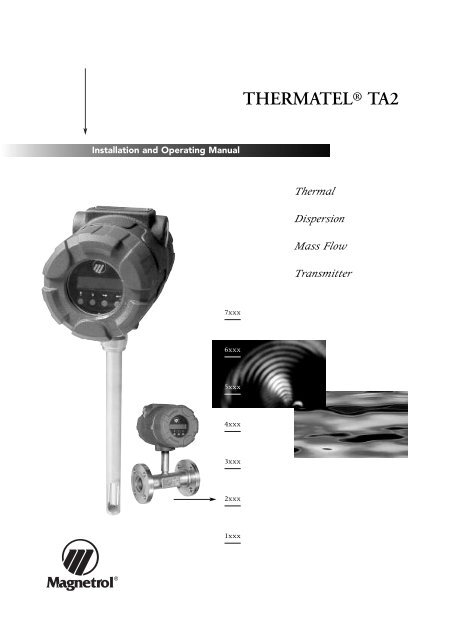
Installation and Operating <strong>Manual</strong><br />
®<br />
7xxx<br />
6xxx<br />
5xxx<br />
4xxx<br />
3xxx<br />
2xxx<br />
1xxx<br />
THERMATEL ® <strong>TA2</strong><br />
Thermal<br />
Dispersion<br />
Mass Flow<br />
Transmitter
2<br />
UNPACKING<br />
Unpack the instrument carefully. Make sure all components<br />
have been removed from the foam protection. Inspect all<br />
components for damage. Report any concealed damage to<br />
the carrier within 24 hours. Check the contents of the carton/crates<br />
against the packing slip and report any discrepancies<br />
to <strong>Magnetrol</strong>. Check the nameplate model number<br />
(Model number/approvals as per inserted separate sheet) to<br />
be sure it agrees with the packing slip and purchase order.<br />
Check and record the serial number for future reference<br />
when ordering parts.<br />
MOUNTING<br />
Pipe<br />
centerline<br />
Flow profiles<br />
Ideal sensor location<br />
is in centre of the pipe<br />
0038<br />
0344<br />
These units are in conformity with the<br />
provisions of:<br />
1. The EMC Directive: 89/336/EEC.<br />
The units have been tested to EN<br />
61000-6-4/2001 and EN 61000-6-<br />
2/2001.<br />
2. Directive 94/9/EC for Equipment or protective system for<br />
use in potentially explosive atmospheres. EC-type examination<br />
certificate number ISSeP02ATEX021X (EEx d<br />
units).<br />
3. The PED directive 97/23/EC (pressure equipment directive).<br />
Safety accessories per category IV module H1.<br />
Pressure ratings of the compression fitting:<br />
Stainless steel ferrules:<br />
70 bar @ + 20 °C (1000 psi @ + 70 °F)<br />
35 bar @ + 200 °C (500 psi @ + 400 °F)<br />
Teflon ferrules:<br />
7 bar (100 psi)<br />
25 mm (1")<br />
Flow is “0”<br />
Flow is 20 % higher than<br />
average velocity, but is<br />
relatively flat in profile<br />
A double elbow further<br />
complicates the flow<br />
profile<br />
Nameplate:<br />
- partnumber<br />
- amplifier<br />
- serial n°<br />
- tag n°<br />
Serial number<br />
probe<br />
CAUTION: When loosening a compression fitting –<br />
beware of the pressure in the pipe. The probe may<br />
blow out of the pipe causing injury and/or damage.<br />
NOTE: Do not install the probe in locations where condensed<br />
moisture can be present. The unit may cause a<br />
false high flow indication. In some cases heat tracing or<br />
insulation of the pipe must be considered to avoid<br />
moisture condensation.<br />
45° 45°<br />
Install the <strong>TA2</strong> in<br />
straight run locations<br />
Turbulent flow profile Flow profile following single elbow<br />
45°<br />
45°<br />
Install the <strong>TA2</strong> sensor at a<br />
45° angle to minimize<br />
moisture drip. Use of different<br />
<strong>TA2</strong>’s as shown at<br />
left is recommended to<br />
optimize the accuracy in a<br />
larger pipe dia.<br />
Gas velocity on the outside of the<br />
elbow is higher<br />
A double elbow further<br />
complicates the flow<br />
profile
Flow profiles<br />
FLOW<br />
FLOW<br />
FLOW<br />
Gas flows around an elbow and creates a swirl<br />
Install the <strong>TA2</strong> further away, the flow profile will redevelop<br />
Mounting recommendations<br />
Display<br />
ø x 15<br />
ø x 20 ø x 3<br />
ø x 35<br />
Connects to J3 on the logic board<br />
The <strong>TA2</strong> has a plug in display (ordered with<br />
the unit or seperately). The display resists<br />
-40 °C (-40 °F), lower temperature will cause<br />
permanent damage to the display. The display<br />
will go blank below -20 °C (-4 °F) but will<br />
recover again once above -20 °C (-4 °F)<br />
Swirl patterns in a pipe Probe in a duct<br />
downstream of elbow<br />
90° elbow<br />
Two 90° elbows in plane<br />
FLOW<br />
ø x 3 ø x 15 ø x 3<br />
ø x 3<br />
Two 90° elbows out of plane<br />
CAUTION: Switch power off<br />
when connecting/disconnecting<br />
the display<br />
<strong>TA2</strong> installed in a large duct<br />
for combustion air control: Probe<br />
is located a short distance from a 90° bend,<br />
providing a repeatable flow measurement that<br />
allows to optimize the operation of the boiler<br />
FLOW<br />
reduction<br />
ø x 15<br />
expansion<br />
FLOW<br />
Not Reccommended<br />
control valve<br />
ø x 3<br />
The display can be rotated in 90° increments.<br />
Remove both mounting screws and reposition<br />
at desired position.<br />
3
4<br />
WIRING<br />
CAUTION: In harzardous area, do NOT power the unit until the cable gland is sealed and the housing<br />
cover of the wiring compartment is screwed down securely / housing locking screw is fastened – disabling<br />
the removal of the cover.<br />
Integral electronics<br />
- + L1 L2/N<br />
TB1<br />
Supply power<br />
Remote electronics<br />
Orange<br />
Brown<br />
Black<br />
Blue<br />
White<br />
Remote probe wiring<br />
5<br />
4<br />
3<br />
2<br />
1<br />
8<br />
7<br />
6<br />
5<br />
4<br />
3<br />
2<br />
1<br />
Shielded twisted<br />
pair cable<br />
A– A+<br />
P– P+<br />
TB2<br />
4 - 20 mA output<br />
Supply power: 24 V DC or 240 / 120 V AC<br />
Output<br />
Shield to ground<br />
Active or Passive output<br />
Ex Non Ex<br />
A- / A+ = active output: power supplied by <strong>TA2</strong><br />
P- / P+ = passive output: power supplied by<br />
external 24 V DC source<br />
Ex Non Ex<br />
8-wire shielded cable –<br />
see MODEL IDENTIFICATION<br />
Shield<br />
White/Orange + Orange/White<br />
White/Brown<br />
Brown/White<br />
White/Blue<br />
Blue/White<br />
White/Green<br />
Green/White<br />
NOTE: Explosion proof cable is labelled<br />
as per terminal number<br />
TB3<br />
Supply power: 24 V DC or 240 / 120 V AC<br />
Output<br />
Shield to ground<br />
1 2 3 4 5 6 7 8<br />
Main electronics wiring<br />
J1<br />
Terminal board on main<br />
electronics
CONFIGURATION<br />
PASSWORD<br />
IMPORTANT: <strong>TA2</strong> units are pre-configured from factory (as per order specifications). Only modify configuration<br />
settings in case needed.<br />
NOTE: When power is first applied to the <strong>TA2</strong> there is an initialization period for the sensor to reach stabilization.<br />
During this time the <strong>TA2</strong> will output a 4 mA signal and the display (if provided) will read «Initializing <strong>TA2</strong>». Only after the<br />
sensor has stabilized and a valid flow measurement is obtained will the display show a flow measurement, the output<br />
signal will be active and the totalizer will begin counting.<br />
Keys Comment<br />
2 line - 16 characters LCD.<br />
Default display cycles every 1,5 s through<br />
FLOW / MASS / TEMPERATURE / TOTALIZED FLOW / mA OUTPUT<br />
UP / DOWN / DELETE and ENTER pushbuttons<br />
(Up) Scroll to the previous selection in the list or<br />
increase a value (behind decimal / negative values show “-”) or<br />
scroll forward through graphical characters.<br />
Hold the key for 1,5 s and the display will scroll faster.<br />
(Down) Scroll to the next selection in the list or<br />
decrease a value (behind decimal / negative values show “-”) or<br />
scroll backward through graphical characters.<br />
Hold the key for 1,5 s and the display will scroll faster.<br />
(Delete) Exit the current item/menu level without changes or<br />
moves the cursor to the left to delete an entry<br />
(Enter) Enter the next menu eg. «System Config» or<br />
enter information for the present selection eg. «Volume Flow» or<br />
Moves the cursor to the right to quit/save a selection (cursor must be in a blank position)<br />
Acces Menu<br />
When attempting to enter a selection setting, the unit will display:<br />
«Usr Passwd Req’d»<br />
«Prb Passwd Req’d»<br />
Display Item Action<br />
User password required<br />
Probe password required*<br />
* only needed when original probe was replaced – factory default is “2200”<br />
Select a new Password<br />
Move to «Adv Config» menu-selection<br />
«Change Password»<br />
to select<br />
Unit shows an encrypted value. Enter<br />
“200” (factory default password or any<br />
modified user password (001 - 999)<br />
Display Item Action<br />
Add new Password for probe replacement<br />
Move to «Factory Config» menu-selection<br />
«Probe Params»<br />
to select<br />
Change password<br />
Enter old password «Enter old password»<br />
Enter new password «Enter new password»<br />
(any value between 001 - 999)<br />
Display Item Action<br />
Probe parameters<br />
Scroll through entries (factors are provided<br />
with the new probe)<br />
Password forgotten/lost – consult factory for assistance, your password can be recooped via the encrypted value displayed<br />
when the Password is asked for (see Acces Menu.)<br />
5
6<br />
CONFIGURATION<br />
Main Menu<br />
The main menu is used to access the various subroutines. From the Run mode, press any key to enter the Main Menu. The<br />
following chart defines the various selections available.<br />
Display Item Action if is pressed<br />
«Measured Value» Measured value Enter Measured Values menu<br />
«System Config» System configuration Enter System Configuration menu<br />
«I/O Config» I/O configuration Enter Input/Output Configuration menu<br />
«Adv Config» Advanced configuration Enter Advanced Configuration menu<br />
«Diagnostics» Diagnostics Enter Diagnostic menu<br />
«Factory Config» Factory configuration Enter Factory Configuration menu<br />
«Run Mode» Run mode Return to Run Mode
CONFIGURATION<br />
Measured Values<br />
The Measured Values menu is used to display the current values measured by the <strong>TA2</strong> and determine which parameters will<br />
be shown on the display during run mode. Enter this section by pressing when «Measured Values » is displayed from the<br />
Main Menu.<br />
Display Item Action Comments<br />
«Volume Flow»<br />
xxxx units<br />
«Mass Flow»<br />
xxxx units<br />
«Temperature»<br />
xxxx units<br />
«Loop Current»<br />
xxxx units<br />
«Totalized Flow»<br />
xxxx units<br />
«Previous Menu»<br />
to select<br />
Volume Flow<br />
Mass Flow<br />
Temperature<br />
Loop Current<br />
Totalized Flow<br />
Previous Menu<br />
Press or to cycle between On main<br />
display «On Main Display» and Off Main<br />
Display «Off Main Display»; press<br />
Press or to cycle between On main<br />
display «On Main Display» and Off Main<br />
Display «Off Main Display»; press<br />
Press or to cycle between On main<br />
display «On Main Display» and Off Main<br />
Display «Off Main Display»; press<br />
Press or to cycle between On main<br />
display «On Main Display» and Off Main<br />
Display «Off Main Display»; press<br />
Press or to cycle between On main<br />
display «On Main Display» and Off Main<br />
Display «Off Main Display»; press<br />
Temperature measurements<br />
are not accurate at velocity<br />
below 0,25 Nm/s<br />
Returns to previous menu<br />
or cycle through measured<br />
values<br />
7
8<br />
CONFIGURATION<br />
System Configuration Menu<br />
The System Configuration menu is used to select the display units and enter specific information for the application. Access<br />
this section by pushing when System Config is displayed from the Main Menu.<br />
To calculate the flow or mass, it is necessary to accurately enter the area of the pipe or duct. If the pipe or duct is circular, simply<br />
enter the value of the inside diameter; the cross sectional area of the pipe is automatically calculated. If the duct is rectangular,<br />
skip over the entry of diameter, and directly enter the cross sectional area in the area section. The instrument will then<br />
back calculate an equivalent diameter.<br />
Display Item Action Comments<br />
«Flow Units<br />
Nm3/h»<br />
«Mass Units<br />
kg/h»<br />
«Temp Units<br />
Celsius»<br />
«Density Units<br />
kg/m3»<br />
«Diameter Units<br />
mm»<br />
«Area Units<br />
m2»<br />
«Flow Area»<br />
to select<br />
Previous Menu<br />
to select<br />
Flow Units Press or to scroll between<br />
selections; press<br />
Mass Units Press or to scroll between<br />
selections; press<br />
Temperature Units Press or to scroll between<br />
selections; press<br />
Density Units Press or to scroll between<br />
selections; press<br />
Diameter Units Press or to scroll between<br />
selections; press<br />
Area Units Press or to scroll between<br />
selections; press<br />
Flow Area Press or to scroll between<br />
selections; press<br />
Diameter «Diameter»<br />
xxx units<br />
Area «Area»<br />
xxx units<br />
Choice of standard cubic feet<br />
per minute «SCFM», standard<br />
cubic feet per hour «SCFH»,<br />
normal cubic meters per hour<br />
«Nm3/h», normal liters per hour<br />
«Nl/h»<br />
Choice of pounds per minute ,<br />
«lbs/M» pounds per hour «lbs/H»,<br />
kilograms per minute «kg/m»,<br />
kilograms per hour «kg/h»<br />
Choice of «Fahrenheit», «Celsius»<br />
Choice of pounds per cubic foot<br />
«lb/ft3», kilograms per liter<br />
«kg/l», kilograms per cubic<br />
meter «kg/m3»<br />
Choice of inches «inches»,<br />
feet «feet», meters «meters»,<br />
millimeters «mm»<br />
Choice of square inches «in2»,<br />
square feet «ft2», meters squared<br />
«m2», millimeters squared «mm2»<br />
Enter the cross sectional area of<br />
the pipe or duct, or the inside<br />
diameter<br />
Enter the inside diameter (if circular),<br />
press to accept or<br />
press or<br />
The cross sectional area is calculated<br />
based on the diameter. If<br />
rectangular enter the flow area<br />
Returns to previous menu or<br />
cycle through System<br />
Configuration
CONFIGURATION<br />
Measured Values<br />
System Config<br />
I/O Config<br />
Adv Config<br />
Diagnostics<br />
Factory Config<br />
Run Mode<br />
Flow Units<br />
Mass Units<br />
Temp Units<br />
Density Units<br />
Diameter Units<br />
Area Units<br />
Flow Area<br />
SCFH<br />
SCFM<br />
Nm3/h<br />
Nl/h<br />
lbs/H<br />
lbs/M<br />
kg/h<br />
kg/m<br />
Fahrenheit<br />
Celsius<br />
lb/ft3<br />
kg/m3<br />
kg/l<br />
inches<br />
feet<br />
meters<br />
mm<br />
in2<br />
ft2<br />
m2<br />
mm2<br />
Diameter<br />
Area<br />
OR<br />
decimal entry in<br />
selected units<br />
Flow Body ID size is entered<br />
from factory<br />
9
10<br />
CONFIGURATION<br />
I/O Configuration Menu<br />
The I/O Configuration menu is used to set up the operations of 4–20 mA output, the totalizer, and the HART Poll Address.<br />
Access this section by pushing when «I/O Config » is displayed.<br />
4-20 mA<br />
To access the 4-20 mA signal, scroll or until the display shows «4-20 mA Config », press .<br />
Display Item Action Comments<br />
«Controlled by<br />
Flow»<br />
«4 mA Set Point<br />
xxxxx units»<br />
«20 mA Set Point<br />
xxxx units»<br />
«Fault Mode<br />
xx mA»<br />
«Previous Menu»<br />
to select<br />
Controlled by flow Press or to cycle between<br />
options<br />
4 mA set point<br />
xxxxx units<br />
20 mA set point<br />
xxxxx units<br />
Fault mode<br />
xx mA<br />
Choice is Flow «Flow»<br />
or Mass «Mass»<br />
Set mA point using keypad Enter value for 4 mA point. Units<br />
are based upon selection<br />
«Controlled by»<br />
Set mA point using keypad Enter value for 20 mA point<br />
Press or to cycle between<br />
«22 mA», «3.6 mA» or «Hold»<br />
Select status of 4-20 mA loop in<br />
event of fault<br />
Previous menu Returns to previous menu or<br />
cycle through 4-20 mA<br />
Totalizer<br />
The totalizer maintains a continuous, running total of the flow in selectable units. It also provides elapsed time since the last<br />
totalizer reset. The totalizer utilizes eeprom memory, eliminating the need for a battery backup. The totalizer can be reset to<br />
zero via the software configuration menu or by the HART communication. When power is interrupted, the totalizer will restore<br />
to its last saved value.<br />
To configure the Totalizer operation, scroll or until the display shows «Totalizer », press .<br />
Display Item Action Comments<br />
«Totalizer Mode<br />
Disable»<br />
«Totalizer Units<br />
xxxxx units»<br />
«Totalized Flow<br />
xxxxx units»<br />
«Elapsed Time<br />
xx.x hours»<br />
«Rst Total to 0»<br />
to select<br />
«Previous Menu»<br />
to select<br />
Totalizer mode disabled Press or to cycle through<br />
options<br />
Totalizer units<br />
xxxxx units<br />
Totalizer flow<br />
xxxxx units<br />
Elapsed time<br />
xx.x hours<br />
Press or to cycle through<br />
options<br />
Enables or disables totalizer<br />
operation<br />
Cycles between «SCF», «Nm3»,<br />
«Nl», «lbs», «kg»<br />
Displays the totalized flow since<br />
last reset<br />
Displays the elapsed time since<br />
the totalizer was last reset<br />
Reset total to 0 Press to reset or to return Resets the totalizer to «0000»<br />
Previous menu Returns to previous menu or<br />
cycle through Totalizer operation<br />
HART Configuration<br />
To configure the HART address, scroll or until the display shows «HART I/O config », press . Note that this menu selection<br />
will appear even on units that are not equipped with HART. If HART communication is desired, ensure that the correct<br />
model is ordered.<br />
NOTE: A non-zero polling address should only be used for multipoint network configuration. In this situation, loop current is<br />
held at 4 mA regardless of the flow rate.<br />
Display Item Action Comments<br />
«HART Poll Addr<br />
0»<br />
«Input HART Tag»<br />
to select<br />
«Previous Menu»<br />
to select<br />
HART poll address Enter value of 0-15 using<br />
keypad<br />
Input HART tag Enter alphanumeric entry for<br />
HART display title<br />
See section “CONFIGURATION” -<br />
page 5 for information on<br />
alphanumeric entry<br />
Previous menu Returns to previous menu or<br />
cycle through HART<br />
Configuration selection
CONFIGURATION<br />
Measured Values<br />
System Config<br />
I/O Config<br />
Adv Config<br />
Diagnostics<br />
Factory Config<br />
Run Mode<br />
4-20 mA Config<br />
Totalizer<br />
HART I/O Config<br />
Controlled by<br />
4 mA Set Point<br />
20 mA Set Point<br />
Fault Mode<br />
Totalizer Mode<br />
Totalizer Units<br />
Totalized Flow<br />
xxxx units<br />
Elapsed Time<br />
xxxx.x hrs<br />
Rst Total to 0<br />
HART Poll Addr<br />
Input HART Tag<br />
Flow<br />
Mass<br />
decimal entry in<br />
selected units<br />
decimal entry in<br />
selected units<br />
22 mA<br />
3.6 mA<br />
Hold<br />
Disabled<br />
Enabled<br />
SCF<br />
Nm3<br />
Nl<br />
lbs<br />
kg<br />
No<br />
Yes<br />
enter 0-15<br />
alphanumeric<br />
entry<br />
(8 characters)<br />
11
12<br />
CONFIGURATION<br />
Advanced Configuration<br />
The Advanced configuration menu sets advance parameters not normally used in the operation of the instrument. To access<br />
Advanced Configuration, scroll or until the display shows «Adv Config », press .<br />
Display Item Action Comments<br />
«Change Password» Change password Enter Old Password<br />
Change the instrument password<br />
to select<br />
Enter New Password<br />
«Damping (0-15) Damping<br />
Using the key pad, enter new Damping factor is given in time<br />
0.0 secs»<br />
0,0 seconds<br />
Damping value 0.0 to 15.0 sec. constants<br />
«STP Conditions» Standard temperature Enter value for Standard Permits user to change STP<br />
to select and pressure conditions Temperature and select<br />
(Standard Temperature and<br />
Standard Pressure value Pressure) conditions<br />
«Install Factors» Install factors Enter new values for A, B & C Permits user to adjust flow mea-<br />
to select<br />
surement. *<br />
«Low Flow Cutoff» Low dropout Enter new low flow dropout The <strong>TA2</strong> will ignore flow readings<br />
value in selected units of below this value;<br />
measurement<br />
See Section “MAINTENANCE” -<br />
Troubleshooting -<br />
Hardware/Application<br />
«Adj Loop Curr»<br />
to select<br />
Adjustment loop current<br />
«4 mA Offset» Use or to adjust loop output<br />
until 4 mA is exact<br />
«20 mA Offset» Use or to adjust loop out-<br />
«Home Menu Title» Home menu title Press then or to cycle<br />
put until 20 mA is exact<br />
The display will show either a<br />
to select<br />
between local tag and HART tag. local tag or the HART tag.<br />
Press to input «Local Tag» See section “CONFIGURATION”<br />
- page 5 for information on<br />
alphanumeric entry.<br />
«Previous Menu» Previous menu Returns to previous menu or cycle<br />
to select<br />
through Advanced Configuration<br />
* Installation factor: Changes in flow profile will affect the measurements of the <strong>TA2</strong>. Advanced users have the ability to adjust the<br />
measurements for changes in flow profile using a polynomial relationship in the form of:<br />
Corrected flow = A+Bv+Cv 2<br />
v = velocity in SFPM (Standard feet/min.). Contact <strong>Magnetrol</strong> for calculations to determine these factors.<br />
The default is B = 1; and A and C = 0. To use the correction factor, develop a relationship between the flow measured by the <strong>TA2</strong> and<br />
the flow measured by a second flowmeter. Curve fit the second order polynomial (above) using the output of the <strong>TA2</strong> and the output of<br />
the second flowmeter for corrected flow. Then enter the appropriate values in the Advanced Configuration menu.
CONFIGURATION<br />
Measured Values<br />
System Config<br />
I/O Config<br />
Adv Config<br />
Diagnostics<br />
Factory Config<br />
Run Mode<br />
Change Password<br />
Damping<br />
STP Conditions<br />
Install Factors<br />
Low Flow Cutoff<br />
Adj Loop Curr<br />
Old Password New Password<br />
Integer Entry Integer Entry<br />
Integer Entry in<br />
Seconds<br />
Temperature<br />
Pressure<br />
A+Bv+Cv 2, A=<br />
A+Bv+Cv 2, B=<br />
A+Bv+Cv 2, C=<br />
Decimal Entry in<br />
Chosen Units<br />
4 mA Offset<br />
inc/dec value<br />
Home Menu Title Title Choice<br />
Local Tag<br />
Input Local Tag<br />
<strong>Magnetrol</strong> <strong>TA2</strong><br />
Decimal Entry in<br />
Chosen Units<br />
1 Atm<br />
1 Bar<br />
Decimal Entry<br />
Decimal Entry<br />
Decimal Entry<br />
20 mA Offset<br />
inc/dec value<br />
Local Tag<br />
HART Tag<br />
13
14<br />
CONFIGURATION<br />
Diagnostics Menu<br />
The Diagnostics menu provides a method of testing the instrument’s functionality. It also has useful information for troubleshooting.<br />
To access Diagnostics, scroll or until the display shows «Diagnostics », press .<br />
Display Item Action Comments<br />
«<strong>TA2</strong> Firmware Ver<br />
x.x mmddyy»<br />
«Test 4-20 Loop»<br />
to select<br />
«Signal Value»<br />
to select<br />
«Calib Check»<br />
to select<br />
«Probe Status»<br />
to select<br />
«Delta Temp<br />
nn.mm»<br />
«Heater Setting<br />
aaaa»<br />
«Exception Code<br />
0»<br />
«Previous Menu»<br />
to select<br />
<strong>TA2</strong> firmware version<br />
x.x month/day/year<br />
Display firmware version number<br />
and date<br />
Test 4-20 loop Enter desired current output Allows user to output desired<br />
4-20 mA signal. Press when<br />
complete to return to normal<br />
operation.<br />
Signal value Displays Sensor signal strength<br />
and corresponding flow rate.<br />
or permits user to change<br />
signal strength and view<br />
calculated flow rate<br />
Calibration check Displays various A/D values.<br />
Press to view Heater Current,<br />
press to exit<br />
Probe status Press or to cycle between<br />
the temperature sensor, flow<br />
sensor and heater<br />
Delta temperature<br />
nn.mm<br />
Heater setting<br />
AAAA<br />
Allows user to vary signal strength<br />
and view flow rate. Press any<br />
button when complete to return<br />
to normal operation. Compare<br />
readings with original calibration<br />
certificate.<br />
This is used with the Probe<br />
Simulation Module.<br />
Displays status of the sensors and<br />
the heater. Status will be either<br />
«OK», «Shorted», or «Open».<br />
Consult <strong>Magnetrol</strong> if a problem is<br />
noted.<br />
Displays the measured temperature<br />
difference between the reference<br />
and heated sensor.<br />
Displays the heater setting used<br />
to obtain the desired temperature<br />
difference. Ranges between 0<br />
and 4095.<br />
Exception code <strong>Magnetrol</strong> use only. Advise<br />
<strong>Magnetrol</strong> if other than 0.<br />
Previous menu Returns to previous menu or<br />
cycle through Diagnostics Menu.
CONFIGURATION<br />
Measured Values<br />
System Config<br />
I/O Config<br />
Adv Config<br />
Diagnostics<br />
Factory Config<br />
Run Mode<br />
<strong>TA2</strong> Firmware Ver<br />
1.0A:mmddyy<br />
Test 4-20 Loop Loop Test Value Loop=xx.xx mA<br />
Decimal Entry Decimal Entry<br />
Signal Values Signal xxx.x mW<br />
xxxx.xx units<br />
Calib Check T RTD=xxxxx<br />
F RTD=xxxxx<br />
Probe Status<br />
Delta Temp<br />
xx.xx<br />
Heater Setting<br />
xxxx<br />
Exception code<br />
0<br />
Temp Sensor<br />
OK<br />
Flow Sensor<br />
OK<br />
Probe Heater<br />
OK<br />
Fxd Sgnl xxx mW<br />
xxxx.xx units<br />
Fixed Htr Curr<br />
xxx mA<br />
Check probe wiring or<br />
consult factory if “shorted”<br />
or “open” is displayed<br />
15
16<br />
CONFIGURATION<br />
Factory Configuration<br />
The Factory Configuration is used during initial calibration of the instrument; access to this section is generally only required<br />
for review of the information.<br />
Replacement of either the probe or the logic circuit board will require re-entry of calibration data. This is accomplished using<br />
the probe password of 2200. A replacement probe will be accompanied with a new calibration certificate which will provide the<br />
new calibration information. Replacement of the logic circuit board will require re-entry of the original calibration data from the<br />
initial calibration certificate. Data under Probe Params, Gas Params, and Ctrl Params will need to be verified or re-entered. See<br />
Section 3.6.<br />
To access Factory Configurations, scroll or until the display shows «Factory Config », press .<br />
Display Item Action Comments<br />
«Probe Params»<br />
to select<br />
«Gas Parameters<br />
to select<br />
«Ctrl Parameters»<br />
to select<br />
«Module Params»<br />
to select<br />
«Temp Calibrate»<br />
xxx.xx»<br />
«Previous menu»<br />
to select<br />
Probe parameters Scroll through entries These factors will require<br />
changing if probe is replaced.<br />
Gas parameters Scroll through entries and compare<br />
against data on the calibration<br />
certificate<br />
Control parameters Scroll through entries and compare<br />
against data on Calibration<br />
Certificate<br />
These factors will require<br />
changing if probe is replaced.<br />
«Gas Calib» mode is used during<br />
factory calibration.<br />
These factors will require<br />
changing if probe is replaced.<br />
Module parameters Scroll through entries These are factory set values and<br />
should not be changed.<br />
Temperature calibrate<br />
xxx.xx<br />
Used by <strong>Magnetrol</strong> during initial<br />
calibration<br />
This value should not be<br />
changed in field.<br />
Previous menu Returns to previous menu or<br />
cycle through Factory<br />
Configuration.
CONFIGURATION<br />
Measured Values<br />
System Config<br />
I/O Config<br />
Adv Config<br />
Diagnostics<br />
Factory Config<br />
Run Mode<br />
Probe Params<br />
Requires Probe<br />
Password<br />
Gas Parameters Temp Corr TCC-A<br />
Requires Probe<br />
Password<br />
Temp Corr TCC-B<br />
Ctrl Parameters Coeff Ratio<br />
Requires Probe<br />
Password<br />
Set Point<br />
Factory password<br />
required – do not<br />
change in field<br />
Temp Calibrate<br />
Factory password<br />
required – do not<br />
change in field<br />
Sensor Type Insertion Probe<br />
Cal Coeffs<br />
R0<br />
F0<br />
Slope<br />
Decimal Entry<br />
Flow Body<br />
Cal Coeff A<br />
Cal Coeff B<br />
Cal Coeff C<br />
Integer Entry<br />
Decimal Entry<br />
Upr Xducer Lmt Decimal Entry<br />
Lwr Xducer Lmt Decimal Entry<br />
Zero Flow Sgnl Decimal Entry<br />
Gas Density<br />
Module Parameters Module Calib<br />
Decimal Entry<br />
Decimal Entry<br />
Decimal Entry<br />
in chosen units<br />
Gas Coeff Ag Decimal Entry<br />
Gas Coeff Bg Decimal Entry<br />
Gas Coeff Cg Decimal Entry<br />
Gas Coeff Dg Decimal Entry<br />
Gas Coeff Eg Decimal Entry<br />
Gas Calib Mode Enable<br />
Disable<br />
Decimal Entry<br />
Decimal Entry<br />
Decimal Entry<br />
Power Predictor Decimal Entry<br />
<strong>Magnetrol</strong> S/N<br />
HART Device ID<br />
Decimal Entry<br />
Decimal Entry<br />
Decimal Entry<br />
Htr Lo Pt Calib<br />
Htr Hi Pt Calib<br />
A-D Lo Pt Calib<br />
Integer Entry A-D Hi Pt Calib<br />
Integer Entry<br />
Final Ass’y Num Integer Entry<br />
17
18<br />
CONFIGURATION USING HART ®<br />
TB1 TB2<br />
Control<br />
Room<br />
Display<br />
Current<br />
Meter<br />
Junction<br />
A– A+<br />
P– P+<br />
TB2<br />
4 - 20 mA output<br />
250 Ω < RL < 1000 Ω<br />
- +<br />
Power<br />
Supply<br />
Wiring<br />
compartment<br />
CONNECTIONS<br />
Connection of your Hart communicator:<br />
• at TB2 terminals (A+) and (A-) in wiring compartment<br />
• at first junction box between unit and control room.<br />
IMPORTANT: The digital HART ® communication is superimposed on the<br />
4-20 mA output and requires a min. load resistance of 250 Ω and a max load<br />
resistance of 1000 Ω.<br />
CHECK HART ®<br />
Before starting the HART ® configuration procedure – check if your HART ® communicator<br />
is equipped with the proper <strong>TA2</strong> Device Descriptors (DD’s).<br />
I/O start up the communicator<br />
Select NO: go offline<br />
Select 4: utility<br />
Select 5: simulation<br />
Check manufacturer: <strong>Magnetrol</strong><br />
HFC Release date Hart Version Compatible with software<br />
July 2002 Dev V1 DD V2 Version 1.0B and earlier<br />
September 2002 Dev V2 DD V1 Version 1.1A<br />
June 2004 Dev V3 DD V1 Version 1.2 and later<br />
See «Configuration» in diagnostics menu for the <strong>TA2</strong> firmware version. When the proper<br />
HART ® software version of the HHU is not found, consult your local HART ®<br />
Service Center to load the correct <strong>TA2</strong> DD’s.<br />
When the proper software version is not found, consult your local HART ® Service<br />
Center to load the correct <strong>Thermatel</strong> <strong>TA2</strong> DD’s.<br />
HART MENU<br />
I/O Start up the device<br />
1 Enter DEVICE SET UP<br />
Press one of the following alphanumeric keys (if no key is sensed after 5 s, the<br />
unit will automatically jump to RUN mode and alternatively show Level/% Output<br />
and Loop signal<br />
1 for entering the Basic Setup «Basic Setup»<br />
2 for entering Advanced Setup «Advanced Setup»<br />
3 for entering Diagnostics «Diagnostics»<br />
4 for entering Device Description «Device Description»<br />
5 for entering Review «Review»<br />
6 for entering Calibration Factors «Cal Factors»
CONFIGURATION USING HART ®<br />
Display Menu<br />
Device Setup<br />
Flow<br />
Mass<br />
Gas Temp<br />
PV Loop<br />
Total<br />
Velocity<br />
1. Basic Setup<br />
2. Advanced Setup<br />
3. Diagnostics<br />
4. Device Description<br />
5. Review see next page<br />
6. Cal Factors<br />
1. System Units<br />
2. Flow Area<br />
3. PV is<br />
4. Variable Selection<br />
5. 4 mA Set Point<br />
6. 20 mA Set Point<br />
7. Fault State<br />
8. Damping<br />
9. Totalizer<br />
10. Date/Time/Initials<br />
1. Low Flow Cutoff<br />
2. Install Factors<br />
3. Adjust Loop Curren<br />
4. STP Conditions<br />
5. Change Password<br />
1. Loop Test<br />
2. Signal/PV<br />
3. Error/Warnings<br />
4. Firmware Version<br />
5. Probe Status<br />
6. Delta T<br />
7. Heater Setting<br />
8. Exception Code<br />
1. Tag<br />
2. Model<br />
3. Manufacturer<br />
4. <strong>Magnetrol</strong> S/N<br />
5. Descriptor<br />
6. Date<br />
7. Message<br />
8. Final Assembly Num<br />
9. Device ID<br />
10. Poll Address<br />
Flow<br />
Mass<br />
3.6 mA<br />
22 mA<br />
Hold<br />
4 mA<br />
20 mA<br />
Other<br />
End<br />
1. Pipe ID<br />
2. Flow Area<br />
1. SV is<br />
2. TV is<br />
3. 4V is<br />
1. Mode<br />
2. Units<br />
3. Total<br />
4. Elapsed Time<br />
5. Reset Total<br />
1. A<br />
2. B<br />
3. C<br />
1. STP Temperature<br />
2. STP Pressure<br />
1. Temp Sensor<br />
2. Flow Sensor<br />
3. Probe Heater<br />
see next page<br />
SCF<br />
Nl<br />
lbs<br />
kg<br />
see next page<br />
Flow<br />
Mass<br />
Gas Temp<br />
Total<br />
1 Atmosphere<br />
1 Bar<br />
19
20<br />
CONFIGURATION USING HART ®<br />
1. Basic Setup<br />
1. System Units<br />
6. Cal Factors<br />
1. Flow<br />
2. Mass<br />
3. Temperature<br />
4. Density<br />
5. Totalized Flow<br />
6. Diameter<br />
7. Area<br />
8. Velocity<br />
1. Enter Password<br />
2. Probe Parameters<br />
3. Gas Parameters<br />
4. Control Parameters<br />
SCFM<br />
Nm3/h<br />
Nl/h<br />
lbs/hr<br />
lbs/m<br />
kg/h<br />
kg/m<br />
C<br />
F<br />
lb/ft3<br />
kg/m3<br />
kg/l<br />
SCF<br />
Nm3<br />
Nl<br />
lbs<br />
kg<br />
inches<br />
feet<br />
meters<br />
mm<br />
in2<br />
ft2<br />
m2<br />
mm2<br />
SF/M<br />
SF/S<br />
Nm/s<br />
1. Sensor Type<br />
2. Ro<br />
3. Fo<br />
5. Review<br />
4. Calibration Coeff<br />
5. Lower Xducer Limit<br />
6. Upper Xducer Limit<br />
7. Zero Flow Signal<br />
1. TCC – A<br />
2. TCC – B<br />
3. Density<br />
4. Gas Coefficients<br />
5. Gas Calibrate Mode<br />
1. Coeff Ratio<br />
2. Set Point<br />
3. Slope<br />
4. Power Predictor<br />
1. Model<br />
2. Manufacturer<br />
3. <strong>Magnetrol</strong> S/N<br />
4. Firmware Version<br />
5. Tag<br />
6. Descriptor<br />
7. Date<br />
8. Message<br />
9. Final Assembly Num<br />
10. Device ID<br />
11. Poll address<br />
12. Flow Units<br />
13. Mass Units<br />
14. Temperature Units<br />
15. Density Units<br />
16. Totalizer Units<br />
17. Diameter Units<br />
18. Area Units<br />
19. Sensor Type<br />
20. Pipe ID<br />
21. Flow Area<br />
22. PV is<br />
23. SV is<br />
24. TV is<br />
25. 4V is<br />
26. 4 mA Set Point<br />
27. 20 mA Set Point<br />
28. Fault State<br />
29. Damping<br />
30. Totalizer Mode<br />
31. Date/Time/Initials<br />
32. Low Flow cutoff<br />
Insertion Probe<br />
Flow Body<br />
1. A<br />
2. B<br />
3. C<br />
1. Ag<br />
2. Bg<br />
3. Cg<br />
4. Dg<br />
5. Eg<br />
33. Install Factor – A<br />
34. Install Factor – B<br />
35. Install Factor – C<br />
36. STP Pressure<br />
37. STP Temperature<br />
38. Ro<br />
39. Fo<br />
40. Cal Coeff – A<br />
41. Cal Coeff – B<br />
42. Cal Coeff – C<br />
43. Lower Xducer Limit<br />
44. Upper Xducer Limit<br />
45. Zero Flow Signal<br />
46. TCC – A<br />
47. TCC – B<br />
48. Density<br />
49. Gas Coeff – Ag<br />
50. Gas Coeff – Bg<br />
51. Gas Coeff – Cg<br />
52. Gas Coeff – Dg<br />
53. Gas Coeff – Eg<br />
54. Gas Calibrate Mode<br />
55. Coeff Ratio<br />
56. Set Point<br />
57. Slope<br />
58. Power Predictor<br />
59. 4 mA Trim Value<br />
60. 20 mA Trim Value<br />
61. Universal rev<br />
62. Field dev rev<br />
63. Software rev<br />
64. Num req preams
MAINTENANCE<br />
Error Messages<br />
Message Action<br />
User password required «Usr Passwd Req’d»<br />
Probe password required «Prb Passwd Req’d»<br />
Re-enter data and correct password<br />
Contact <strong>Magnetrol</strong> Technical Support for assistance<br />
Error new pasword failed «Err New Pwd Failed» When changing the password, the second entry of the new password<br />
does not match the first entry<br />
Error:max «Error:max» Entry of numeric data is outside the acceptable range. Maximum<br />
allowed value is displayed<br />
Error:min «Error:min» Entry of numeric data is outside the acceptable range. Minimum<br />
allowed value is displayed<br />
Factory password required «Fct Passwd Req’d» You are attempting to access Factory Calibration data. This requires the<br />
Factory Password. This data should not be changed in the field.<br />
The <strong>TA2</strong> has continuous self diagnostics which detect many specific faults. In the unlikely event of a fault, one or more of the<br />
following messages may appear on the display. If there is more than one error message, the messages will rotate. During the<br />
time a fault is detected, the loop current is held at the fault level (selected under I/O Configuration) and the totalizer does not<br />
accumulate.<br />
Message Action<br />
No Probe Signals «No Probe Signals» Check Probe Status section of Diagnostics to determine cause of problem.<br />
Probe Hardware Fault «Probe Hdwr Fault» Check probe wiring<br />
The following displays will occur on re-initialization or in the event of non-volatile memory error. The instrument may need to be<br />
reconfigured following the procedure in System Configuration Menu – see page 7 & 8.<br />
Message Action<br />
Probe Parameters Reset «Prb Params Reset» Re-enter the probe calibration data using the probe password<br />
User Parameters Reset «Usr Params Reset» Reconfigure the instrument for flow area and 4-20 mA setup<br />
Initializing <strong>TA2</strong> «Initializing <strong>TA2</strong>» The <strong>TA2</strong> is going through initialization. Flow measurement will begin<br />
after completion of the initialization.<br />
Module Calibration Required «Module Cal Req’d» The <strong>TA2</strong> electronics require re-calibration. The instrument<br />
continues to operate at reduced accuracy, contact <strong>Magnetrol</strong> Technical<br />
Support.<br />
21
22<br />
MAINTENANCE<br />
Troubleshooting - Hardware/Application<br />
Symptom Problem Solution<br />
No output signal<br />
No display<br />
Troubleshooting Guide - Firmware<br />
No input power Verify that LED D6 on the wiring board is on.<br />
Check connection TB1 on input wiring board.<br />
Check wiring connection to J1 on power supply board.<br />
No output signal 4-20 mA not operational Verify 4-20 mA connections are made to the active terminals<br />
– see wiring page 4<br />
Flow Rate too high<br />
or too low<br />
Instrument configuration<br />
does not match<br />
customer set up<br />
Flow Rate too high Flow Profile<br />
Considerations<br />
Check value entered for Flow Area under System Configuration<br />
Check STP conditions under Advanced Configuration<br />
User can correct for variations in flow profile using the “Install<br />
Factors” under Advanced Configuration – See page 12.<br />
Moisture in the Gas Condensed moisture will cool the sensor more than gas flow.<br />
This will temporarily indicate a higher than expected flow<br />
rate. Relocate the probe to another location.<br />
Flow rate too low Probe incorrectly oriented Check orientation of the probe in the pipe. Flow arrow on<br />
probe must be pointed in the direction of flow<br />
Flow is measured<br />
under a no flow<br />
condition<br />
Sensor is dirty Build up on the sensor will reduce heat transfer and produce<br />
lower than expected signal. Clean the sensor<br />
Increased heat transfer<br />
(can occur under no flow<br />
and high pressure<br />
conditions)<br />
Symptom Problem Solution<br />
Password Invalid User changed password,<br />
but does not remember<br />
new password<br />
Increase the Low Flow Cutoff «Low Flow Cutoff» to a value > the<br />
displayed flow rate. The <strong>TA2</strong> will ignore flow readings below<br />
this value.<br />
Go to Change Password «Change Password» under Advanced<br />
configuration «Advanced Configuration». Press .<br />
Enter any value under Enter old password “Enter Old Passw”<br />
and press . The display will give an encrypted number.<br />
Notify <strong>Magnetrol</strong> of the encrypted number. We can then convert<br />
the encrypted number to the password which the user<br />
previously selected.<br />
Totalizer not operating Totalizer not Enabled Insure that the totalizer operation is enabled under the<br />
Totalizer section of the I/O Configuration Menu – See page 10<br />
Flow measurement<br />
on display is correct<br />
but Output signal<br />
always 4 mA<br />
HART devices only:<br />
handheld will only<br />
read Universal<br />
Commands<br />
HART Poll Address<br />
is not 0<br />
The most current Device<br />
Descriptions (DDs) are not<br />
installed in the handheld.<br />
Change HART Poll Address to 0. – See page 10.<br />
Contact local HART service center for the latest DDs.
MAINTENANCE<br />
Resistance Values - Integral electronics<br />
The resistance values for the probe can be checked using J6 on the logic board. To check resistances, turn off power and open<br />
the enclosure. Remove the plug in display board if provided. The following table gives the expected resistances. Refer to Figure<br />
for pin locations.<br />
Pin Function Expected Resistance<br />
1-9 Reference PT1000 1000 to 1770 Ω*<br />
3-9 Reference PT1000 1000 to 1770 Ω*<br />
5-9 Heated PT1000 1000 to 1770 Ω*<br />
7-9 Heated PT1000 1000 to 1770 Ω*<br />
13-9 Heater 20 Ω<br />
* The resistance can be calculated using the formula<br />
R = 1000 x (1 + 0.00385 x Temperature)<br />
Temperature is in °C. Resistance on the other pins will be dependent upon wire length but will be less than 3 Ω.<br />
C1<br />
C10<br />
J6 Terminal Block Pin Location<br />
Resistance Values - Remote electronics<br />
The table below shows the expected resistance values in case remote electronics are used.<br />
5<br />
4<br />
3<br />
2<br />
1<br />
8<br />
7<br />
6<br />
5<br />
4<br />
3<br />
2<br />
1<br />
C26<br />
C25<br />
C4<br />
R21 R10 R35<br />
R11<br />
R49<br />
R47<br />
U3<br />
R42<br />
R46<br />
R50<br />
C29<br />
R43<br />
R2<br />
R3<br />
R5<br />
U5<br />
R45<br />
U7<br />
R48<br />
C28<br />
2<br />
R22<br />
1<br />
X1<br />
D3<br />
R6<br />
J3<br />
R51<br />
D7<br />
R7<br />
R23<br />
C2<br />
U1<br />
C7<br />
R17<br />
C30<br />
R52<br />
R53<br />
R8<br />
Pin Function Expected Resistance<br />
1-3 Reference RTD 1000 to 1770 Ω<br />
2-3 Heated RTD 1000 to 1770 Ω<br />
4-5 Heater 20 Ω<br />
C9<br />
R16<br />
R19<br />
C11<br />
R18<br />
R15<br />
C8<br />
R12<br />
R13<br />
R14<br />
R4<br />
R54<br />
R9<br />
R20<br />
R58<br />
R1<br />
R57<br />
R29<br />
R60<br />
1<br />
P5<br />
P7<br />
U2<br />
R61<br />
C14<br />
D1<br />
C23<br />
C12<br />
R31<br />
C13<br />
C15<br />
C17<br />
R40<br />
C3<br />
C18<br />
R36<br />
C19<br />
13 11 9 7 5 3 1<br />
Heater Power<br />
Measuring the voltage between pins 13 and 9 can approximate the power to the heated sensor. The power can be estimated<br />
by the following formula:<br />
Power = Voltage 2 (Volt 2) / 20 (Ω)<br />
This value can be compared against the Signal Strength measured in the Diagnostics menu. – See section “CONFIGURA-<br />
TION”.<br />
23
24<br />
PROBE SIMULATION MODULE<br />
The <strong>Magnetrol</strong> Probe Simulation Module (089-5220-001) can be used with the <strong>TA2</strong> Thermal Dispersion Mass Flow Meter to<br />
compare the readings of the transmitter against a reference.<br />
Using the Probe Simulation Module requires the use of the Display in the <strong>TA2</strong>.<br />
Connecting the probe simulation module<br />
1. Unscrew cover and remove the screws attaching the<br />
display. Do not disconnect the display from the circuit<br />
board.<br />
2. Remove the jumper from J6. See figure below.<br />
3. Plug in the cable from the probe simulation module<br />
into J6. This removes the probe from the circuit and<br />
readings are now from the module (<strong>TA2</strong> display will<br />
read «Probe Hdwe Fault»).<br />
4. Put the switch to the High position.<br />
5. Using the <strong>TA2</strong> display, move to Diagnostics/Calib<br />
Check and record the values of T RTD and F RTD<br />
below.<br />
6. Put the switch to the Low position and record the values<br />
of T RTD and F RTD below.<br />
NOTE: If there is little change between readings in the<br />
High and Low position, turn the plug in J6 over and try<br />
again.<br />
<strong>TA2</strong> probe simulation module<br />
C26<br />
C25<br />
C4<br />
R21 R10 R35<br />
R11<br />
R49<br />
R47<br />
U3<br />
R42<br />
R46<br />
R50<br />
C29<br />
R43<br />
R2<br />
R3<br />
R5<br />
U5<br />
R45<br />
U7<br />
R48<br />
C28<br />
2<br />
R22<br />
1<br />
X1<br />
D3<br />
R6<br />
J3<br />
R51<br />
D7<br />
R7<br />
R23<br />
C2<br />
C1<br />
U1<br />
C7<br />
R17<br />
C30<br />
7. Press Enter and the display will read:<br />
«Fixed Htr Curr<br />
Xxx mA»<br />
Record these values below.<br />
T RTD<br />
F TRD<br />
Fixed Htr Curr<br />
Voltage<br />
High Low<br />
8. Measure and record the voltage between the two pins<br />
on the probe simulation module.<br />
9. At a future date compare the readings with the values<br />
recorded above.<br />
R52<br />
R53<br />
R8<br />
C9<br />
R16<br />
C10<br />
R19<br />
C11<br />
R18<br />
R15<br />
C8<br />
R12<br />
R13<br />
R14<br />
R4<br />
R54<br />
R9<br />
R20<br />
R58<br />
R1<br />
R57<br />
R29<br />
R60<br />
1<br />
P5<br />
P7<br />
U2<br />
R61<br />
C14<br />
D1<br />
C23<br />
C12<br />
R31<br />
C13<br />
C15<br />
C17<br />
R40<br />
C3<br />
C18<br />
R36<br />
C19<br />
J6 terminal block pin location<br />
13 11 9 7 5 3 1
PROBE REPLACEMENT<br />
The probe and the electronics are calibrated together to form a matched set. However, if a probe needs to be replaced,<br />
<strong>Magnetrol</strong> can provide a replacement probe and probe calibration information which the user can configure into the instrument.<br />
Each probe has a serial number; when originally provided with the electronics, the electronics and the probe will have the same<br />
serial number; if the probe is later replaced, it will have a different serial number than the electronics.<br />
NOTE: When replacing the probe in the field, the accuracy may be slightly effected.<br />
Integral Electronics<br />
1. Make sure the power source is turned off.<br />
2. Remove and unplug the display module if provided.<br />
3. Remove the board set consisting of the logic board and<br />
the power supply board.<br />
4. Probe wiring connections are made on the back side of<br />
the logic board at TB3. – See wiring section, page 4.<br />
5. Disconnect the electrical wires at J1.<br />
6. Disconnect the wires at TB3.<br />
7. Disconnect the probe from the enclosure.<br />
8. Reinstall the new probe making sure that the flow arrow<br />
is in the direction of flow.<br />
9. Re-connect the probe wiring to the terminal block using<br />
the following connections:<br />
Wire Color Terminal<br />
White 1<br />
Blue 3<br />
Black 5<br />
Brown 6<br />
Orange 7<br />
Remote Electronics<br />
1. Make sure the power source is turned off.<br />
2. Remove the wires connecting the probe to the five<br />
position sensor terminal block.<br />
3. Remove the probe from the enclosure and carefully pull<br />
out the wires from the bottom of the enclosure.<br />
Optionally, it may be easier to temporarily remove the<br />
terminal block from the enclosure by removing the two<br />
attachment screws.<br />
4. Install new probe and make probe connections as<br />
shown in “WIRING” section.<br />
10. Reconnect the electrical wires at J1.<br />
11. Reinstall the circuit boards in the enclosure and the display<br />
module if provided.<br />
12. Apply power.<br />
13. Proceed to Programming.<br />
Electronic<br />
Section<br />
Wiring Color Code<br />
Wire Terminal Sensor<br />
White Sensor 1 Temp Sensor<br />
Blue Sensor 2 Flow Sensor<br />
Black Sensor 3 Ground<br />
Brown Sensor 4 Heater Ground<br />
Orange Sensor 5 Heater<br />
Remote Probe Wiring Connection<br />
25
26<br />
PROBE REPLACEMENT<br />
Programming<br />
At this point, the <strong>TA2</strong> needs to be reconfigured with the new<br />
probe calibration information; this can be done with either<br />
the display module or via HART.<br />
Before reprogramming the <strong>TA2</strong>, first record the value for<br />
Zero Flow Signal. This is obtainable from either the original<br />
calibration certificate or from the value presently stored in<br />
the instrument under «Factory Config» / «Probe Params» / «Zero<br />
Flow Sgnl». If using HART, this value is found under «Device<br />
Setup» / «Cal Factors» / «Probe Parameters»/ «Zero Flow Signal».<br />
Display Module<br />
1. Press until the display shows «Factory Config »,<br />
press .<br />
2. Press until the display shows «Probe Params »,<br />
press .<br />
3. Press and enter the information under Probe<br />
4.<br />
Params listed in Table 1. This information is provided<br />
on the Probe Calibration Certificate which is included<br />
with the replacement probe. The password is 2200; it<br />
is also specified on the Probe Calibration Certificate.<br />
This password cannot be changed.<br />
Repeat for entry of data for «Gas Parameters» and «Ctrl<br />
Parameters» shown in Table 1.<br />
NOTE: For more information on firmware menu, see<br />
Diagnostics Menu – section “CONFIGURA-<br />
TION”.<br />
5. Skip to “Complete the programming”.<br />
«Probe Params» «Gas Parameters» «Ctrl Parameters»<br />
«Cal Coeffs A, B, C»<br />
«R0»<br />
«F0»<br />
«Upr Xducer»<br />
«Lwr Xducer Lmt»<br />
«Zero Flow Sgnl»<br />
«TCC–A»<br />
«TCC–B»<br />
«Gas Density»<br />
«Gas Coeff Ag, Bg,<br />
Cg»<br />
Table 1<br />
LOGIC BOARD REPLACEMENT<br />
«Coeff Ratio»<br />
«Set Point»<br />
«Slope»<br />
«Power Predictor»<br />
HART<br />
Using the HART handheld, from the Main Menu go to<br />
«Device Setup» / «Cal Factors». Then enter the probe password<br />
of 2200. Then enter the new calibration data from the<br />
Calibration Certificate into the appropriate sections of<br />
Probe Parameters «Probe Parameters», Gas Parameters<br />
«Gas Parameters», and Control Parameters «Control<br />
Parameters» / Zero Flow Signal «Zero Flow Signal». See Table<br />
1 for list of new parameters.<br />
Complete the Programming<br />
To complete the reconfiguration, a new set point must be<br />
calculated.<br />
1. Place the probe in ambient temperature air where<br />
there is no flow across the sensor. This can be accomplished<br />
by wrapping the sensor tip with a piece of<br />
paper.<br />
2. Display Module – Go to «Diagnostics» / «Signal value».<br />
HART – Go to the «Device» / «Setup» / «Diagnostics» /<br />
«Signal PV». Allow time for the signal to stabilize to within<br />
±1 mW. Record the signal.<br />
3. Calculate a new Set Point value by using the following<br />
formula:<br />
«New Set Point» = Set Point *(Zero Flow Signal/Signal)<br />
• The «Set Point» is the value on the new cal cert<br />
• «Zero Flow Signal» is the original value obtained in<br />
Display Menu – page 19/20.<br />
• Signal is the value measured under step 2.<br />
NOTE: If the <strong>TA2</strong> is calibrated for a gas other than air,<br />
there are two ZFS (Zero Flow Signal) values on<br />
the certificate. One is ZFS-air and the second is<br />
ZFS-gas. Use the ZFS-air value when making<br />
an adjustment in air.<br />
4. Enter this New set point value «New Set Point Value»<br />
(instead of the value on the calibration certificate) into<br />
the <strong>TA2</strong> under «Factory Config» / «Ctrl Parameters» or if<br />
using HART at «Device Setup» / «Cal Factors» / «Control<br />
Parameters» / «Set Point».<br />
5. Return to the Signal value as shown in step 2 ensuring<br />
that there is no flow over the sensor. The signal value<br />
«Signal Value» should now agree with the original Zero<br />
Flow Signal within 1%. If desired, steps 2 through 5 can<br />
be repeated.<br />
Replacement of the Logic circuit board also requires re-entry of the calibration data from the original calibration certificate.<br />
Follow the procedure as described in programming (see above).
REPLACEMENT PARTS<br />
NOTE: Replacement of the Logic Circuit Board or the Probe requires entry of configuration data from the Calibration<br />
Certificate.<br />
CAUTION: EXPLOSION HAZARD<br />
Do not disconnect equipment unless power has been switched off or the area is known to be<br />
non-hazardous<br />
Item Description Part Number<br />
1 Power Supply Board Integral electronics Z30-2226-001<br />
Remote electronics Z30-2226-003<br />
2 Logic Board English Version Z30-2227-001<br />
German Version Z30-2227-002<br />
French Version Z30-2227-003<br />
3 Display Module Z30-2228-001<br />
4 Input Wiring Board 120 VAC Z30-2230-001<br />
240 VAC Z30-2230-002<br />
24 VDC Z30-2230-003<br />
5 Feed Through 037-3312-001<br />
6 Enclosure O-ring 012-2201-240<br />
7 Enclosure Base 004-9207-XXX<br />
8 Short Enclosure Cover * 004-9197-005<br />
9 Tall Enclosure Cover 004-9206-008<br />
10 Enclosure Cover with Window ** 036-4411-001<br />
11 Probe Enclosure Base 004-9104-001<br />
12 Probe Enclosure Cover 004-9105-001<br />
13 Probe Enclosure O-ring 012-2101-345<br />
14 Remote PC Board 030-2231-001<br />
15 Probe See Probe / Flow body<br />
Model Number<br />
* Short enclosure cover used with units without display<br />
** Enclosure cover with window used with units with display<br />
13<br />
12<br />
11<br />
14<br />
10<br />
3<br />
8<br />
2<br />
6<br />
1<br />
1<br />
5<br />
7<br />
6<br />
15<br />
9<br />
8<br />
4<br />
27
28<br />
SPECIFICATIONS<br />
Functional/physical<br />
Description Specification<br />
19 – 29 V DC<br />
Power supply<br />
204 – 260 V AC, 50-60 Hz<br />
102 – 132 V AC, 50-60 Hz<br />
Power consumption 6 W – 9 V A<br />
Signal Output<br />
Active<br />
Passive<br />
4-20 mA isolated (3,8 – 20,5 mA useable as per NAMUR NE 43) -<br />
max 1000 Ω loop resistance<br />
4-20 mA isolated (3,8 – 20,5 mA useable as per NAMUR NE 43) -<br />
max loop resistance depending power supply<br />
Resolution<br />
Analog<br />
Display<br />
0,01 mA<br />
0,01 Nm/s<br />
Calibration Pre-calibrated from factory - NIST traceable<br />
Damping Adjustable 0-15 s time constant<br />
Diagnostic Alarm Adjustable 3,6 mA, 22 mA or Hold<br />
User Interface 4-button keypad and/or HART ® communicator<br />
Display 2-line x 16-character LCD<br />
Displayed values<br />
Flow (eg. Nm3/h, Nl/h) and/or mass flow (eg. kg/h) and/or temperature (°C/°F)<br />
and/or loop current (mA) and/or totalized flow (eg. Nm3/h, Nl/h)<br />
Menu Language English, French or German<br />
Housing Material IP 66, Aluminium A 356 (< 0,2 % copper) dual compartment<br />
ATEX II 2G EEx d IIC T6, explosion proof<br />
Approvals<br />
FM, explosion proof (Groups B, C and D) and non incendive<br />
CSA, explosion proof (Groups B, C and D)<br />
RosTechnadzor/GOST-R, Russian authorisation standards<br />
SIL (Safety Integrity Level)<br />
Functional safety to SIL1/SIL2 in accordance to IEC 61508 – SFF: 69 %.<br />
Full FMEDA report and declaration sheets available at request.<br />
Net and gross weight 3,3 kg (7.3 lbs) net; 4,0 kg (8.8 lbs) gross (amplifier with 25 cm threaded probe)<br />
Performance<br />
Description Specification<br />
Turn down ratio 100:1 typical (depending upon calibration)<br />
Flow range<br />
Max<br />
Min<br />
0,13 - 200 Nm/s (25 - 40,000 SFPM) reference of air at STP conditions<br />
0,13 - 2,5 Nm/s (25 - 500 SFPM) reference of air at STP conditions<br />
Linearity Included in flow accuracy<br />
Accuracy<br />
Flow<br />
Temperature<br />
± 1 % of reading + 0,5 % of calibrated full scale<br />
± 1 °C (2 °F)<br />
Repeatability ± 0,5 % of reading<br />
Response time Time constant of 1 to 2 s<br />
Remote electronics Max 15 m (50') away from probe - for longer lengths, consult factory<br />
Ambient temperature -40 °C up to +70 °C (-40 °F up to +160 °F) – display not readable below -20 °C (-4 °F)<br />
Operating temp. effect ± 0,04 % per °C<br />
Humidity 99 %, non-condensing<br />
Electromagnetic Compatibility<br />
Meets CE requirements (EN-61000-6-4, EN 61000-6-2) and are in compliance with<br />
EMC directive 89/336/EEC<br />
Probe specifications<br />
Description Insertion probe Sensor with flow body<br />
Materials – wetted parts 316/316L (1.4401/1.4404) or Hastelloy C (2.4819)<br />
Sensor: 316/316L (1.4401/1.4404)<br />
Flow body: stainless steel or carbon steel<br />
Mounting<br />
Threaded, compression fitting, ANSI-DIN flanged<br />
or with Retractable probe assembly<br />
Threaded or flanged<br />
Probe length From 70 mm up to 2530 mm (2.6" up to 100") Flow body sizes from 1/2" up to 4"<br />
Integral electronics: -45 °C up to +120 °C<br />
Max. process temperature<br />
Remote electronics:<br />
-45 °C up to +200 °C with 100 mm (4")<br />
longer probe serving as heat extension<br />
-45 °C up to +200 °C<br />
Max pressure rating<br />
103 bar (1500 psi) @ +20 °C (+70 °F)<br />
95 bar (1375 psi) @ +200 °C (+400 °F) – direct insertion<br />
75 bar (1100 psi) @ +200 °C (+400 °F) – with flow body
MODEL IDENTIFICATION<br />
A complete measuring system consists of:<br />
1. <strong>Thermatel</strong> ® <strong>TA2</strong> mass flow electronics.<br />
<strong>Thermatel</strong> ® <strong>TA2</strong> mass flow transmitters require an application report for performing pre-calibration from factory. Ask<br />
your magnetrol ® contact for assistance when specifying a device.<br />
2. <strong>Thermatel</strong> ® <strong>TA2</strong> mass flow insertion probe or <strong>Thermatel</strong> ® <strong>TA2</strong> mass flow sensor with flow body.<br />
3. Connecting cable for remote mount <strong>Thermatel</strong> ® <strong>TA2</strong> mass flow transmitters<br />
4. Options:<br />
- portable display module – order number: 089-5219-001<br />
- probe simulation module – order number: 089-5220-001 (for more details see page 24)<br />
- retractable probe assembly (RPA) – (for order code see page 32)<br />
- valve and compression fitting – order number: 089-5218-001 (for more details see page 32)<br />
- duct mounting bracket – order number: 089-7247-001 (for more details see page 33)<br />
- compression fittings – (for order code see page 33).<br />
1. Code for <strong>Thermatel</strong> ® <strong>TA2</strong> Mass Flow transmitter<br />
T A 2 <strong>Thermatel</strong> ® BASIC MODEL NUMBER<br />
<strong>TA2</strong> Mass Flow transmitter<br />
INPUT VOLTAGE<br />
2 24 V DC<br />
1 240 V AC<br />
0 120 V AC<br />
SIGNAL OUTPUT<br />
1 4-20 mA with HART communication<br />
ACCESSORIES<br />
0 Blind transmitter (can receive the plug in display as future option)<br />
B Plug in digital display and keypad<br />
MENU LANGUAGE (HART communication is only available in English language)<br />
1 English<br />
3 French<br />
4 German<br />
ACTUAL GAS CALIBRATION<br />
For <strong>TA2</strong> with insertion probe<br />
0 Special. Specify medium separately<br />
1 Air<br />
2 Nitrogen or Oxygen<br />
3 Hydrogen<br />
For <strong>TA2</strong> with sensor with flow body<br />
A Special. Specify medium separately<br />
B Air<br />
C Nitrogen or Oxygen<br />
D Hydrogen<br />
4 Natural gas<br />
5 Methane<br />
6 Digester gas<br />
7 Propane<br />
E Natural gas<br />
F Methane<br />
G Digester gas<br />
H Propane<br />
AIR EQUIVALENCY CALIBRATION<br />
Air equivalency values are available for various gases, consult factory for gases and<br />
flow rates.<br />
9 For <strong>TA2</strong> with insertion probe<br />
K For <strong>TA2</strong> with sensor with flow body<br />
MOUNTING/CLASSIFICATION (Consult factory for FM/CSA approvals)<br />
3 Integral, General Purpose (FM/CSA explosion proof)<br />
4 Remote, General Purpose (FM/CSA explosion proof)*<br />
C Integral, ATEX II 2G EEx d II C T6, explosion proof<br />
D Remote, ATEX II 2G EEx d II C T6, explosion proof*<br />
* Bracket for electronics and probe housing included<br />
HOUSING MATERIAL / CABLE ENTRY<br />
1 IP 66, Cast aluminium - M20 x 1,5 cable entry (2 entries - one plugged)<br />
0 IP 66, Cast aluminium - 3/4" NPT cable entry (2 entries - one plugged)<br />
T A 2 1<br />
complete code for <strong>Thermatel</strong> ® <strong>TA2</strong> Mass Flow transmitter<br />
29
30<br />
MODEL IDENTIFICATION<br />
2. Code for <strong>Thermatel</strong> ® <strong>TA2</strong> Mass Flow probe<br />
T M R <strong>Thermatel</strong> ® <strong>TA2</strong> Mass Flow probe<br />
MATERIALS OF CONSTRUCTION<br />
A 316/316L (1.4401/14404) stainless steel<br />
B Hastelloy C (2.4819) - not available with compression fitting<br />
PROCESS CONNECTION<br />
0 0 0 Compression fitting - min 11 cm insertion length (compression fittings are not included,<br />
for proper order numbers – see page 6). Only available with 316/316L (1.4401/1.4404).<br />
Consult factory for Hastelloy C (2.4819)<br />
Threaded<br />
1 1 0 3/4" NPT - default selection in combination with a retractable probe assembly (RPA) see page 32<br />
2 1 0 1" NPT<br />
2 2 0 1" BSP (G1)<br />
ANSI flanges<br />
2 3 0 1" 150 lbs - RF flange<br />
2 4 0 1" 300 lbs - RF flange<br />
3 3 0 1 1/2" 150 lbs - RF flange<br />
3 4 0 1 1/2" 300 lbs - RF flange<br />
4 3 0 2" 150 lbs - RF flange<br />
4 4 0 2" 300 lbs - RF flange<br />
EN/DIN flanges<br />
B A 0 DN 25 PN 16 EN 1092-1 Type A<br />
B B 0 DN 25 PN 25/40 EN 1092-1 Type A<br />
C A 0 DN 40 PN 16 EN 1092-1 Type A<br />
C B 0 DN 40 PN 25/40 EN 1092-1 Type A<br />
D A 0 DN 50 PN 16 EN 1092-1 Type A<br />
D B 0 DN 50 PN 25/40 EN 1092-1 Type A<br />
INSERTION LENGTH - consider process connections<br />
Min probe length<br />
0 0 7 7 cm (2,6") fix length - for NPT threaded<br />
0 0 9 9 cm (3,5") fix length - for BSP threaded<br />
Selectable probe length - specify per 1 cm (0,39") increments<br />
0 0 9 min. 9 cm (3,5") - for NPT threaded and flanged<br />
0 1 1 min. 11 cm (4,5") - for BSP threaded and compression fitting<br />
0 2 5 min. 25 cm (10") - for use with RPA (Retractable Probe Assembly)<br />
2 5 3 max. 253 cm (99,9") - for all probe connections<br />
T M R 0<br />
complete code for <strong>Thermatel</strong> ® <strong>TA2</strong> mass flow insertion probe
MODEL IDENTIFICATION<br />
2. Code for <strong>Thermatel</strong> ® <strong>TA2</strong> sensor with flow body<br />
T F T <strong>Thermatel</strong> ® BASIC MODEL NUMBER<br />
<strong>TA2</strong> sensor with mass flow body<br />
MATERIALS OF CONSTRUCTION<br />
A 316/316L (1.4401/1.4404) stainless steel body and sensor<br />
1 Carbon steel body / stainless steel sensor<br />
THREADED FLOW BODY - ø size and connection<br />
0 1 1/2" NPT<br />
1 1 3/4" NPT<br />
2 1 1" NPT<br />
3 1 1 1/2" NPT<br />
4 1 2" NPT<br />
FLANGED FLOW BODY - ø size and connection<br />
0 3 1/2" 150 lbs RF flange<br />
1 3 3/4" 150 lbs RF flange<br />
2 3 1" 150 lbs RF flange<br />
3 3 1 1/2" 150 lbs RF flange<br />
4 3 2" 150 lbs RF flange<br />
5 3 3" 150 lbs RF flange<br />
6 3 4" 150 lbs RF flange<br />
Accessoires<br />
0 None<br />
1 Stainless steel flow conditioning plate - for flow body sizes ≥ 11/2" T F T 0 0 0 complete code for <strong>Thermatel</strong> ® <strong>TA2</strong> sensor with flow body<br />
3. Code for connecting cable remote mount <strong>Thermatel</strong> ® <strong>TA2</strong> Mass Flow transmitter<br />
0 3 7 – 3 3 1 4 General purpose connecting cable - 8 wire shielded instrument cable<br />
0 0 9 – 8 2 7 0 ATEX explosion proof connecting cable - 8 wire shielded instrument cable<br />
CABLE LENGTH - specify per 1 cm (0,39") increments<br />
0 0 3 min 3 m (10') length<br />
0 1 5 max 15 m (50') length<br />
0 complete code for connecting cable<br />
31
32<br />
MODEL IDENTIFICATION<br />
4. Code for retractable probe assembly<br />
BASIC MODEL NUMBER<br />
R P A Retractable probe assembly<br />
DESIGN TYPE<br />
E Low pressure - up to 5,5 bar (80 psi)<br />
F High pressure - up to 300 lbs / service<br />
MATERIALS OF CONSTRUCTION<br />
1 Carbon steel with 316 SST (1.4401) seal gland<br />
4 316 SST (1.4401)<br />
PROCESS CONNECTION<br />
0 1 1/2" NPT – not available for RPA-E1<br />
1 1 1/2" - 150 lbs RF flange<br />
2 1 1/2" - 300 lbs RF flange<br />
0<br />
BALL VALVE<br />
No ball valve supplied<br />
1 Carbon steel ball valve – select material code 1<br />
2 Stainless steel ball valve – select material code 4<br />
PROBE LENGTH<br />
0 2 5 min 25 cm (10")<br />
2 5 3 max 253 cm (99,9")<br />
R P A complete code for retractable probe assembly<br />
DIMENSIONS IN mm (inches)<br />
Adjustment<br />
rods<br />
Adjustment<br />
nuts<br />
Ball valve<br />
Vessel wall<br />
V<br />
Retaining bar<br />
Seal nut<br />
Customer<br />
connection<br />
Hot tap<br />
Model RPA-FX12-XXX<br />
minimum probe length: T = 2 (X + Y)<br />
X<br />
Y<br />
T<br />
Seal nut<br />
1 1/2" NPT<br />
Ball valve<br />
Vessel wall<br />
Safety cable<br />
V<br />
Customer<br />
connection<br />
Hot tap<br />
Model RPA-E402-XXX<br />
minimum probe length: S + X + Y<br />
S<br />
X<br />
Y<br />
S Dimension<br />
Threaded connection 102 (4.00)<br />
Flanged connection 127 (5.00)<br />
Ball Valve Dimensions*<br />
Size V<br />
1 1 ⁄2" NPT 112 (4.4)<br />
11 ⁄2" 150# flange 165 (6.5)<br />
11 ⁄2" 300# flange 190 (7.5)<br />
*Dimension of ball valve if supplied by the factory.<br />
200 (8)<br />
Typical<br />
1" NPT<br />
customer<br />
supplied<br />
Valve with compression fitting<br />
(089-5218-001)
DIMENSIONS IN mm (inches)<br />
Integral Mount <strong>TA2</strong><br />
165<br />
(6.49)<br />
Typical height<br />
when compression<br />
fitting is used with<br />
half coupling or<br />
threadolet<br />
Process<br />
Conn. Size<br />
A<br />
114 (4.49)<br />
Pipe<br />
centerline 25 mm (1)<br />
Remote Mount <strong>TA2</strong><br />
3/4" NPT or M20<br />
(2 entries - one plugged)<br />
2 holes<br />
Ø 10<br />
(0.38)<br />
51<br />
(2.00)<br />
70<br />
(2.75)<br />
89<br />
(3.50)<br />
Duct mounting bracket<br />
Ø 152,4<br />
(6.00)<br />
Height<br />
A<br />
1" NPT 79 (3.1)<br />
3⁄4" NPT 66 (2.6)<br />
160<br />
(6.30)<br />
76<br />
(3.00)<br />
3/4" NPT<br />
connection<br />
Optional<br />
compression<br />
fitting<br />
95<br />
(3.75)<br />
3/4" NPT or M20<br />
connection<br />
(2 entries - one<br />
plugged)<br />
3/4" or 1" NPT<br />
recommended<br />
114 (4.49)<br />
Duct mounting bracket with 3⁄4" NPT<br />
part number 089-7247-001 or<br />
089-7247-002 (includes hardware)<br />
3/4" NPT<br />
or M20<br />
transducer<br />
cable connector<br />
Compression fitting<br />
3/4" NPT<br />
or M20<br />
70<br />
(2.75)<br />
82<br />
(3.23)<br />
Insertion<br />
length<br />
NPT thread<br />
Dimension A:<br />
85 (3.33) without display<br />
99 (3.88) with display<br />
Teflon ferrules Stainless steel ferrules<br />
011-4719-009<br />
(6,90 bar maximum)<br />
011-4719-008<br />
(6,90 bar maximum)<br />
011-4719-007<br />
(69 bar maximum)<br />
011-4719-006<br />
(69 bar maximum)<br />
118 (4.63)<br />
3/4"<br />
Insertion length<br />
BSP thread /<br />
compression fitting<br />
Insertion<br />
length<br />
flanged<br />
A<br />
85 (3.33)<br />
5.18<br />
(132)<br />
33
34<br />
DIMENSIONS IN mm (inches)<br />
Code Size<br />
L1<br />
L<br />
With Flow<br />
Conditioning<br />
mm (inches)<br />
A<br />
Length (L) L1 Height to<br />
Without Flow<br />
Conditioning<br />
mm (inches)<br />
With Flow<br />
Conditioning<br />
mm (inches)<br />
B<br />
Without Flow<br />
Conditioning<br />
mm (inches)<br />
L1<br />
L<br />
Centerline<br />
(A)<br />
mm (inches)<br />
A<br />
Overall Height (B)<br />
NPT-F<br />
mm (inches)<br />
B<br />
Flange<br />
mm (inches)<br />
0 1/2" 203 (8) ➀ — 127 (5) ➀ — 203 (8.0) 221 (8.7) 248 (9.75)<br />
1 3/4" 286 (11.25) ➀ — 190 (7.5) ➀ — 203 (8.0) 221 (8.7) 251 (9.9)<br />
2 1" 381 (15) ➀ — 254 (10) ➀ — 203 (8.0) 221 (8.7) 257 (10.1)<br />
3 1 1/2" 495 (19.5) 191 (7.5) 305 (12) 95 (3.75) 212 (8.35) 236 (9.3) 276 (10.85)<br />
4 2" 660 (26) 191 (7.5) 406 (16) 95 (3.75) 235 (9.25) 264 (10.4) 311 (12.25)<br />
5 3" 991 (39) 254 (10) 610 (24) 127 (5) 235 (9.25) N/A 330 (13.0)<br />
6 4" 1321 (52) 305 (12) 914 (36) 152 (6) 235 (9.25) N/A 349 (13.75)<br />
Code Size<br />
0<br />
1<br />
1 ⁄2"<br />
3 ⁄4"<br />
2 1"<br />
3 1 1 ⁄2"<br />
4 2"<br />
5 3"<br />
6 4"<br />
Flanged flow body Threaded flow body<br />
➀ The upstream length in pipe sizes < 1 1/2" dia. is sufficient to create the flow conditioning effect without need for a flow conditioning plate.<br />
Flow body sizing<br />
The following table is a general guide on flow sizing. Contact your <strong>Magnetrol</strong> contact for specific application information.<br />
Air, N2, O2<br />
110 NM 3/h<br />
65 SCFM<br />
204 NM3/h 120 SCFM<br />
340 NM3/h 200 SCFM<br />
833 NM 3/h<br />
490 SCFM<br />
1220 NM3/h 715 SCFM<br />
3000 NM3/h 1765 SCFM<br />
5490 NM3/h 3230 SCFM<br />
Natural Gas,<br />
Methane<br />
76 NM3/h 45 SCFM<br />
140 NM3/h 85 SCFM<br />
238 NM3/h 140 SCFM<br />
580 NM3/h 340 SCFM<br />
855 NM3/h 505 SCFM<br />
2110 NM3/h 1240 SCFM<br />
3845 NM3/h 2260 SCFM<br />
Max flow rate<br />
Digester<br />
Gas<br />
Propane Hydrogen CO2, Argon<br />
42 NM3/h 51 NM<br />
25 SCFM<br />
3/h 27 NM<br />
30 SCFM<br />
3/h 105 NM<br />
15 SCFM<br />
3/h<br />
60 SCFM<br />
76 NM3/h 93 NM<br />
45 SCFM<br />
3/h 52 NM<br />
55 SCFM<br />
3/h 190 NM<br />
30 SCFM<br />
3/h<br />
110 SCFM<br />
127 NM3/h 161 NM<br />
75 SCFM<br />
3/h 85 NM<br />
95 SCFM<br />
3/h 320 NM<br />
50 SCFM<br />
3/h<br />
190 SCFM<br />
310 NM3/h 395 NM<br />
180 SCFM<br />
3/h 208 NM<br />
230 SCFM<br />
3/h 790 NM<br />
120 SCFM<br />
3/h<br />
465 SCFM<br />
480 NM3/h 600 NM<br />
280 SCFM<br />
3/h 332 NM<br />
350 SCFM<br />
3/h 1155 NM<br />
195 SCFM<br />
3/h<br />
680 SCFM<br />
1180 NM3/h 1470 NM<br />
695 SCFM<br />
3/h 812 NM<br />
860 SCFM<br />
3/h 2855 NM<br />
475 SCFM<br />
3/h<br />
1680 SCFM<br />
2145 NM3/h 2675 NM<br />
1265 SCFM<br />
3/h 1478 NM<br />
1575 SCFM<br />
3/h 5210 NM<br />
865 SCFM<br />
3/h<br />
3060 SCFM
Flow Reference<br />
Gas Type<br />
Tag Number<br />
Electronics Serial #<br />
Probe Serial #<br />
Flow Units<br />
Mass Units<br />
Temp Units<br />
Density Units<br />
Diameter Units<br />
Area Units<br />
Diameter<br />
Area<br />
4-20 Controlled by<br />
4 mA Set Point<br />
20 mA Set Point<br />
Fault State<br />
Totalizer Mode<br />
Totalizer Units<br />
Totalized Flow<br />
Elapsed Time<br />
HART Poll Address<br />
HART Tag<br />
Damping<br />
STP Temperature<br />
STP Pressure<br />
Install Factor A<br />
Install Factor B<br />
Install Factor C<br />
Low Vel Dropout<br />
4mA offset<br />
®<br />
<strong>Thermatel</strong> Model <strong>TA2</strong><br />
Thermal Dispersion Mass Flow Transmitter<br />
Configuration Data Sheet<br />
20 mA offset<br />
Local Tag<br />
Firmware Version<br />
Signal Value<br />
Temperature Sensor<br />
Flow Sensor<br />
Probe Heater<br />
Delta Temp<br />
Heater Setting<br />
Exception code<br />
Sensor Type<br />
Cal Coeff A<br />
Cal Coeff B<br />
Cal Coeff C<br />
Ro<br />
Fo<br />
Upr Xducer Lmt<br />
Lwr Xducer Lmt<br />
Zero Flow Signal<br />
TCC-A<br />
TCC-B<br />
Gas Density<br />
Gas Coeff Ag<br />
Gas Coeff Bg<br />
Gas Coeff Cg<br />
Gas Coeff Dg<br />
Gas Coeff Eg<br />
Gas Calibrate Mode<br />
Coeff Ratio<br />
Set Point<br />
Slope<br />
Power Predictor<br />
35
IMPORTANT<br />
SERVICE POLICY<br />
Owners of <strong>Magnetrol</strong> products may request the return of a control; or, any part of a control for complete rebuilding or<br />
replacement. They will be rebuilt or replaced promptly. <strong>Magnetrol</strong> <strong>International</strong> will repair or replace the control, at no cost to<br />
the purchaser, (or owner) other than transportation cost if:<br />
a. Returned within the warranty period; and,<br />
b. The factory inspection finds the cause of the malfunction to be defective material or workmanship.<br />
If the trouble is the result of conditions beyond our control; or, is NOT covered by the warranty, there will be charges for labour<br />
and the parts required to rebuild or replace the equipment.<br />
In some cases, it may be expedient to ship replacement parts; or, in extreme cases a complete new control, to replace the<br />
original equipment before it is returned. If this is desired, notify the factory of both the model and serial numbers of the<br />
control to be replaced. In such cases, credit for the materials returned, will be determined on the basis of the applicability of<br />
our warranty.<br />
No claims for misapplication, labour, direct or consequential damage will be allowed.<br />
RETURNED MATERIAL PROCEDURE<br />
So that we may efficiently process any materials that are returned, it is essential that a “Return Material Authorisation” (RMA)<br />
form will be obtained from the factory. It is mandatory that this form will be attached to each material returned. This form is<br />
available through <strong>Magnetrol</strong>’s local representative or by contacting the factory. Please supply the following information:<br />
1. Purchaser Name<br />
2. Description of Material<br />
3. Serial Number and Ref Number<br />
4. Desired Action<br />
5. Reason for Return<br />
6. Process details<br />
All shipments returned to the factory must be by prepaid transportation. <strong>Magnetrol</strong> will not accept collect shipments.<br />
All replacements will be shipped FOB factory.<br />
UNDER RESERVE OF MODIFICATIONS<br />
®<br />
www.magnetrol.com<br />
BULLETIN N°: BE 54-<strong>630</strong>.3<br />
EFFECTIVE: JULY 2006<br />
SUPERSEDES: November 2004<br />
BENELUX Heikensstraat 6, 9240 Zele, België<br />
Tel. +32 (0)52.45.11.11 • Fax. +32 (0)52.45.09.93 • E-Mail: info@magnetrol.be<br />
DEUTSCHLAND Alte Ziegelei 2-4, D-51491 Overath<br />
Tel. 02204 / 9536-0 • Fax. 02204 / 9536-53 • E-Mail: vertrieb@magnetrol.de<br />
FRANCE 40 - 42, rue Gabriel Péri, 95130 Le Plessis Bouchard<br />
Tél. 01.34.44.26.10 • Fax. 01.34.44.26.06 • E-Mail: magnetrolfrance@magnetrol.fr<br />
ITALIA ViaArese 12, I-20159 Milano<br />
Tel. (02) 607.22.98 (R.A.) • Fax. (02) 668.66.52 • E-Mail: mit.gen@magnetrol.it<br />
UNITED Unit 1 Regent Business Centre, Jubilee Road Burgess Hill West Sussex RH 15 9TL<br />
KINGDOM Tel. (01444) 871313 • Fax (01444) 871317 • E-Mail: sales@magnetrol.co.uk<br />
INDIA E-22, Anand Niketan, New Delhi - 110 021<br />
Tel. 91 (11) 41661840 • Fax 91 (11) 41661843 • E-Mail: info@magnetrolindia.com