Instruction Manual - Magnetrol International
Instruction Manual - Magnetrol International
Instruction Manual - Magnetrol International

Create successful ePaper yourself
Turn your PDF publications into a flip-book with our unique Google optimized e-Paper software.
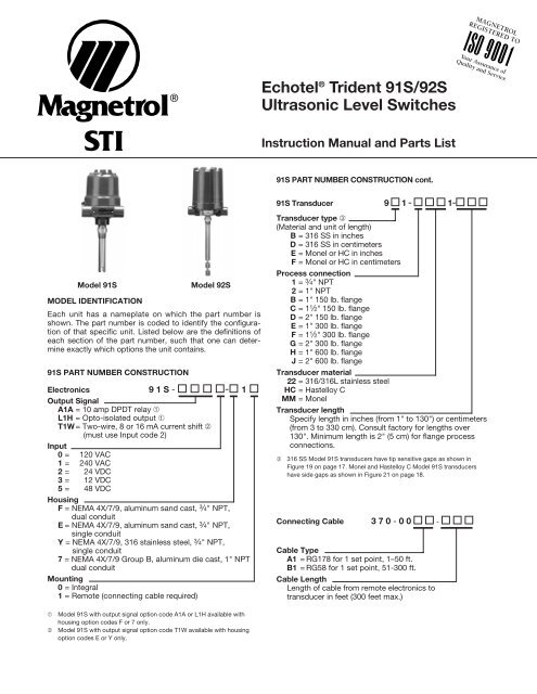
Model 91S Model 92S<br />
MODEL IDENTIFICATION<br />
Each unit has a nameplate on which the part number is<br />
shown. The part number is coded to identify the configuration<br />
of that specific unit. Listed below are the definitions of<br />
each section of the part number, such that one can determine<br />
exactly which options the unit contains.<br />
®<br />
91S PART NUMBER CONSTRUCTION<br />
Electronics 9 1 S - - 1<br />
Output Signal<br />
A1A = 10 amp DPDT relay ➀<br />
L1H = Opto-isolated output ➀<br />
T1W= Two-wire, 8 or 16 mA current shift ➁<br />
(must use Input code 2)<br />
Input<br />
0 = 120 VAC<br />
1 = 240 VAC<br />
2 = 24 VDC<br />
3 = 12 VDC<br />
5 = 48 VDC<br />
Housing<br />
F = NEMA 4X/7/9, aluminum sand cast, 3 ⁄4" NPT,<br />
dual conduit<br />
E = NEMA 4X/7/9, aluminum sand cast, 3 ⁄4" NPT,<br />
single conduit<br />
Y = NEMA 4X/7/9, 316 stainless steel, 3 ⁄4" NPT,<br />
single conduit<br />
7 = NEMA 4X/7/9 Group B, aluminum die cast, 1" NPT<br />
dual conduit<br />
Mounting<br />
0 = Integral<br />
1 = Remote (connecting cable required)<br />
➀ Model 91S with output signal option code A1A or L1H available with<br />
housing option codes F or 7 only.<br />
➁ Model 91S with output signal option code T1W available with housing<br />
option codes E or Y only.<br />
Echotel ® Trident 91S/92S<br />
Ultrasonic Level Switches<br />
<strong>Instruction</strong> <strong>Manual</strong> and Parts List<br />
91S PART NUMBER CONSTRUCTION cont.<br />
91S Transducer 9 1 - 1-<br />
Transducer type ➂<br />
(Material and unit of length)<br />
B = 316 SS in inches<br />
D = 316 SS in centimeters<br />
E = Monel or HC in inches<br />
F = Monel or HC in centimeters<br />
Process connection<br />
1 = 3 ⁄4" NPT<br />
2 = 1" NPT<br />
B = 1" 150 lb. flange<br />
C = 1 1 ⁄2" 150 lb. flange<br />
D = 2" 150 lb. flange<br />
E = 1" 300 lb. flange<br />
F = 1 1 ⁄2" 300 lb. flange<br />
G = 2" 300 lb. flange<br />
H = 1" 600 lb. flange<br />
J = 2" 600 lb. flange<br />
Transducer material<br />
22 = 316/316L stainless steel<br />
HC = Hastelloy C<br />
MM = Monel<br />
Transducer length<br />
Specify length in inches (from 1" to 130") or centimeters<br />
(from 3 to 330 cm). Consult factory for lengths over<br />
130". Minimum length is 2" (5 cm) for flange process<br />
connections.<br />
➂ 316 SS Model 91S transducers have tip sensitive gaps as shown in<br />
Figure 19 on page 17. Monel and Hastelloy C Model 91S transducers<br />
have side gaps as shown in Figure 21 on page 18.<br />
Connecting Cable 3 7 0 - 0 0 -<br />
Cable Type<br />
A1 = RG178 for 1 set point, 1–50 ft.<br />
B1 = RG58 for 1 set point, 51-300 ft.<br />
Cable Length<br />
Length of cable from remote electronics to<br />
transducer in feet (300 feet max.)
92S PART NUMBER CONSTRUCTION<br />
Electronics 9 2 S - - 1<br />
Output Signal<br />
A1A = 10 amp DPDT relay ➃<br />
L1H = Opto-isolated output ➃<br />
T1W= Two-wire, 8 or 16 mA current shift ➄<br />
(must use Input code 2)<br />
Input<br />
0 = 120 VAC<br />
1 = 240 VAC<br />
2 = 24 VDC<br />
3 = 12 VDC<br />
5 = 48 VDC<br />
Housing<br />
E = NEMA 4X/7/9, aluminum sand cast, 3 ⁄4" NPT,<br />
single conduit<br />
Y = NEMA 4X/7/9, 316 stainless steel, 3 ⁄4" NPT,<br />
single conduit<br />
7 = NEMA 4X/7/9 Group B, aluminum die cast, 1" NPT<br />
dual conduit<br />
Mounting<br />
0 = Integral<br />
1 = Remote (connecting cable required)<br />
➃ Model 92S with output signal option code A1A or L1H available with<br />
housing option code 7 only.<br />
➄ Model 92S with output signal option code T1W available with housing<br />
option codes E, Y, and 7.<br />
2<br />
92S PART NUMBER CONSTRUCTION cont.<br />
92S Transducer 9 2 - 1-<br />
Transducer type ➅<br />
(Unit of length)<br />
B = Inches<br />
D = Centimeters<br />
Process connection<br />
1 = 3 ⁄4" NPT<br />
2 = 1" NPT<br />
B = 1" 150 lb. flange<br />
C = 1 1 ⁄2" 150 lb. flange<br />
D = 2" 150 lb. flange<br />
E = 1" 300 lb. flange<br />
F = 1 1 ⁄2" 300 lb. flange<br />
G = 2" 300 lb. flange<br />
H = 1" 600 lb. flange<br />
J = 2" 600 lb. flange<br />
Transducer material<br />
22 = 316/316L stainless steel<br />
HC = Hastelloy C<br />
MM = Monel<br />
Transducer length<br />
Specify “A” dimension (see Figure XX) in inches (from 1"<br />
to 130") or centimeters (from 3 to 330 cm). Consult factory<br />
for lengths over 130". Minimum length is 2" (5 cm)<br />
for flange process connections.<br />
➅ All Model 92S transducers (316 SS, HC, and Monel) have dual side gaps,<br />
as shown in Figure 17 on page 17<br />
Connecting Cable 3 7 0 - 0 0 -<br />
Cable Type<br />
A2 = RG178 for 2 set point, 1–50 ft.<br />
B2 = RG58 for 2 set point, 51-300 ft.<br />
Cable Length<br />
Length of cable from remote electronics to<br />
transducer in feet (300 feet max.)
PRINCIPLE OF OPERATION<br />
The Trident Model 91S/92S operates on a two crystal<br />
pulsed or “transmit-receive” principle which applies a high<br />
frequency electronic burst to the transmit crystal. The signal<br />
is then converted into ultrasonic sound energy and transmitted<br />
across the sensing gap toward the receive crystal. When<br />
air is in the gap, the high frequency sound energy will be<br />
attenuated, thereby not allowing the energy to be received.<br />
When there is liquid in the gap, the sound energy will propagate<br />
across the gap and the relay control or current shift<br />
output will indicate such a reception of the signal.<br />
Self testing is accomplished without any additional crystals<br />
and a minimum of additional circuitry. The electronics detection<br />
circuit looks for low amplitude signals that pass between<br />
CAUTION: Phono jack plugs are fragile. Do not pull<br />
plugs from PC board by pulling coaxial cable.<br />
1. See appropriate wiring for Four-Wire/Two-Wire and single<br />
point/dual point models (pages 4–10) and wire unit.<br />
2. Fill a suitable container with water.<br />
3. Place transducer gap in the liquid.<br />
NOTE: THE AMPLIFIER BOARD AND POWER SUPPLY<br />
BOARD WILL BE DISCUSSED THROUGHOUT THIS MAN-<br />
UAL. THE POWER SUPPLY BOARD IS SHOWN IN FIG-<br />
URES 4, 5, 6, AND 7, DEPENDING ON THE VERSION. THE<br />
AMPLIFIER BOARD IS SHOWN IN FIGURES 9, 11, AND 12.<br />
Single point (91S) models<br />
Relay Versions: Once the liquid fills the gap, there<br />
should be an audible click as the relay changes state.<br />
Also, the red LED marked LED1 (WET) on the amplifier<br />
board will illuminate. Depending on how the unit is configured,<br />
the red LED marked DS1 on the power supply<br />
board may also illuminate. For the purposes of this preliminary<br />
check, only the LEDs on the amplifier board are<br />
pertinent.<br />
Current Shift Versions: Once the liquid fills the gap, the<br />
current output value should change from 8 mA to 16 mA,<br />
and LED1 (WET) on the amplifier board will illuminate.<br />
Dual point (92S) models<br />
Relay Versions: Place the lower transducer gap in the<br />
liquid. There will be an audible click as the relay changes<br />
state. The red LED marked LED1 (WET) on the bottom<br />
amplifier board will illuminate. Continue to immerse the<br />
transducer until the top gap is filled with liquid. Once<br />
MOUNTING POSITION AND LOCATION<br />
Unit may be mounted in any position or orientation. Refer to<br />
Figures 1 and 2.<br />
Direction of<br />
Level Movement<br />
Figure 1<br />
Horizontal Mounting<br />
(91S only)<br />
GENERAL INFORMATION<br />
PRELIMINARY OPERATIONAL CHECK<br />
MOUNTING POSITION AND LOCATION<br />
Figure 2 – Vertical Mounting<br />
PRINCIPLE OF OPERATION cont.<br />
the crystals through the frame of the sensor. This allows the<br />
entire sensor, including the bond between the crystals and<br />
the sensor face, to be tested along with the electronics.<br />
UNPACKING/SPECIAL HANDLING CONSIDERATIONS<br />
Before unpacking the unit, please familiarize yourself with<br />
the procedures and cautions regarding the handling of<br />
Electrostatic Discharge (ESD) sensitive equipment.<br />
CAUTION: Trident Model 91S/92S units are Electrostatic<br />
Discharge (ESD) sensitive instruments. Follow ESD handling<br />
procedures on page 4 when servicing this equipment<br />
to avoid circuit damage.<br />
Dual point (92S) models cont.<br />
again, there will be an audible click as the relay changes<br />
state and the red LED marked LED1 (WET) on the top<br />
board will illuminate.<br />
Current Shift Versions: Once liquid fills the lower gap,<br />
the current output value should change from 8 mA to 16<br />
mA, and the red LED marked LED1 (WET) on the bottom<br />
amplifier board will illuminate. Continue to immerse the<br />
transducer until the top gap is filled with liquid. Once<br />
again, the current output value will change from 8 mA to<br />
16 mA and the red LED marked LED1 (WET) on the top<br />
amplifier board will illuminate.<br />
4. Remove transducer from the liquid. The control output<br />
must deactuate or current shift value return to 8 mA* and<br />
the green LED marked LED2 (DRY) will illuminate. In case<br />
of malfunction consult the Troubleshooting section on<br />
page 15.<br />
MANUAL SELF-TEST<br />
Wet Self Test: With power applied to the instrument and no<br />
liquid in the sensor gap, press switch S2 marked WET<br />
TEST on the amplifier board. Red LED1 (WET) on the<br />
amplifier and DS1 power supply board will illuminate, and<br />
green LED marked LED2 (DRY) on the amplifier board will<br />
extinguish.<br />
<strong>Manual</strong> Self Test: Press switch S1 marked MALF TEST on<br />
the amplifier board. With P2 jumper on the amplifier board<br />
in (HIGH) position both LEDs on the amplifier board will illuminate.<br />
With P2 jumper in (LOW) position, both LEDs will<br />
extinguish. Output current should be 19 mA or 5 mA<br />
respectively.*<br />
* Two wire (current shift) models only.<br />
MOUNTING POSITION AND LOCATION cont.<br />
When installed in a nozzle or pipe, the transducer gap must<br />
extend into the tank beyond the inside tank wall. Refer to<br />
Figure 3.<br />
Figure 3 – Horizontal Mounting in Nozzle<br />
All wiring, conduit and electrical fittings must conform to<br />
local electrical codes for the location selected.<br />
3
91S SINGLE POINT WIRING<br />
CAUTION: Never tighten unit to the tank connection by<br />
turning the housing. Use a wrench on the transducer<br />
mounting nut flats. Use thread tape or suitable pipe compound<br />
on threads. Do not over tighten.<br />
1. Screw transducer into the vessel opening using pipe<br />
compound or thread tape. If flanged, bolt unit to mating<br />
flange with proper gasket.<br />
2. Remove housing cover.<br />
3. No. 14 AWG wire size is recommended for power and<br />
relay wiring.<br />
4. Route wires into housing. Prevent moisture seepage into<br />
the enclosure by installing approved seal-drain fittings in<br />
the conduit run leading to the unit.<br />
NOTE: FOR 91S 120/240 VAC W/OPTO-ISOLATED OUT-<br />
PUT, REFER TO FIGURE 5 ON PAGE 5. FOR 91S 24 VDC<br />
W/OPTO-ISOLATED OUTPUT, REFER TO FIGURE 6 ON<br />
PAGE 5.<br />
4<br />
TB1<br />
ELECTROSTATIC DISCHARGE (ESD) HANDLING PROCEDURE<br />
<strong>Magnetrol</strong>’s electronic instruments are manufactured to the<br />
highest quality standards. These instruments utilize electronic<br />
components which may be damaged by static electricity<br />
present in most work environments. The following<br />
steps are recommended to reduce the risk of component<br />
failure due to electrostatic discharge:<br />
1. Ship and store circuit boards in anti-static bags. If an<br />
anti-static bag is not available, wrap board in aluminum<br />
foil. Do not place boards on foam packing materials.<br />
Power<br />
Wiring<br />
Alarm Relay<br />
Terminal Block<br />
Malfunction<br />
Relay Terminals<br />
(+) L1<br />
(–) N<br />
NC<br />
CO<br />
NO<br />
TB2<br />
NO1 NC1 CO2<br />
CO1 NO2 NC2<br />
Figure 4<br />
91S Relay Output, 120/240 VAC Power Supply Board<br />
2. Use a grounding wrist strap when installing and removing<br />
circuit boards. A grounded workstation is also recommended.<br />
3. Handle printed circuit boards only by the edges. Do not<br />
touch components or connector pins.<br />
4. Ensure that all electrical connections are completely<br />
made and none are partial or floating. Ground all<br />
equipment to a good, earth ground.<br />
FOUR-WIRE MODELS (RELAY or OPTO-ISOLATED VERSIONS)<br />
INSTALLATION/WIRING<br />
91S SINGLE POINT WIRING cont.<br />
5. Attach power leads to power terminal block TB1 on left<br />
side of power supply PC board. Power to properly marked<br />
terminals ([+]L1 and [–]N). Run ground wire to green screw<br />
on bracket. Refer to Figure 4 for 120/240 VAC version.<br />
6. Run alarm relay wiring to terminal block TB2.<br />
7. Dress wiring to ensure no interference or contact with<br />
cover or circuit board components.<br />
OBSERVE ALL APPLICABLE ELECTRICAL CODES AND<br />
PROPER WIRING PROCEDURES.<br />
NOTE: IF REMOTE SELF-TEST IS USED, FOLLOW<br />
INSTRUCTIONS ON PAGE 6.<br />
8. If using the malfunction relay, run wiring to lower portion<br />
of TB1 as shown in Figure 4.<br />
9. Replace housing cover.<br />
CAUTION: In hazardous areas, do not power the unit<br />
until the conduit is sealed and enclosure cover is<br />
screwed down securely.<br />
Malf. Test<br />
Wet Test<br />
Common<br />
Remote Self Test<br />
Terminal Block (TB3)<br />
Alarm-Malfunction<br />
Relay Action (P2)<br />
High/Low Level<br />
Failsafe Selection (P1)
TB1<br />
TB1<br />
Power Wiring<br />
Malfunction<br />
Relay<br />
Terminals<br />
Power Wiring<br />
Malfunction<br />
Relay<br />
Terminals<br />
FOUR-WIRE MODELS (RELAY/OPTO-ISOLATED)<br />
INSTALLATION/WIRING cont.<br />
Alarm Relay<br />
Terminal Block<br />
(+) L1<br />
(–) N<br />
NC<br />
CO<br />
NO<br />
Alarm Relay<br />
Terminal Block<br />
TB2<br />
NO1 CO1 NC1 NO2 CO2 NC2<br />
Figure 5<br />
91S Opto-Isolated Output, 120/240 VAC Power Supply Board<br />
(+) L1<br />
(–) N<br />
NC<br />
CO<br />
NO<br />
TB2<br />
NO1 CO1 NC1 NO2 CO2 NC2<br />
Figure 6<br />
91S Opto-Isolated Output, 24 VDC Power Supply Board<br />
Malf. Test<br />
Wet Test<br />
Common<br />
Alarm-Malfunction<br />
Relay Action (P2)<br />
Remote Self Test<br />
Terminal Block (TB3)<br />
High/Low Level<br />
Failsafe Selection (P1)<br />
Malf. Test<br />
Wet Test<br />
Common<br />
Alarm-Malfunction<br />
Relay Action (P2)<br />
High/Low Level<br />
Failsafe Selection (P1)<br />
Remote Self Test<br />
Terminal Block (TB3)<br />
5
92S DUAL POINT WIRING<br />
1. Run power leads to power terminal block TB1 on the<br />
lower left side of the power supply board. Refer to<br />
Figure 7.<br />
2. Run alarm relay wiring for upper (top) level point to TB2<br />
and lower (bottom) level point to TB3.<br />
3. If using malfunction relay, run wiring to upper terminals<br />
marked TB1. Remember, only one malfunction relay is<br />
present for both boards.<br />
4. Auto fill or auto empty can be accomplished with the<br />
use of one control relay.<br />
TB1<br />
6<br />
Power<br />
Wiring<br />
High/Low Level<br />
Failsafe Switch (S1)<br />
Top<br />
Point Relay<br />
Terminal<br />
Block (TB2)<br />
Malfunction<br />
Relay<br />
Terminals<br />
FOUR-WIRE MODELS (RELAY/OPTO-ISOLATED)<br />
INSTALLATION/WIRING cont.<br />
NC2<br />
CM2<br />
NO2<br />
NC1<br />
CM1<br />
NO1<br />
NO<br />
CM<br />
NC<br />
N (–)<br />
L1 (+)<br />
Top Point Relay LED (DS2)<br />
Figure 7<br />
92S Dual Point Relay Output 120/240 VAC Power Supply Board<br />
REMOTE MANUAL SELF-TEST WIRING (91S/92S)<br />
Remote self test is accomplished by connecting remote<br />
test switches to terminal block TB3 for 91S. For 92S, connect<br />
remote test switches to TB4 and TB5.<br />
NOTE: The remote manual self test terminal block is not<br />
available on the two-wire loop-powered single and dual<br />
point versions.<br />
1. Use single twisted pair 18-22 AWG wire to connect to<br />
TB3 on single point power supply board, or TB4 and<br />
TB5 for dual point.<br />
2. Determine whether a manual test on a wet condition or<br />
malfunction is desirable. (See page 15.)<br />
DO NOT WIRE SEPARATE 12 VDC POWER SOURCE TO<br />
GENERATE POWER FOR REMOTE PUSH BUTTON SELF<br />
TEST. POWER IS ALREADY AT THE TERMINALS.<br />
3. Run one wire of the twisted pair to the W (wet) or<br />
M (malfunction) position. Run the second wire of the pair<br />
to the blank terminal position marked C (common).<br />
Bottom Point Relay Terminal Block (TB3)<br />
NO1 CM1 NC1 N02 CM2 NC2<br />
Malfunction Relay LED (DS1)<br />
Bottom Point<br />
Relay LED (DS3)<br />
Control Functions<br />
Switch (S2)<br />
Malf. Test<br />
Wet Test<br />
Common<br />
Malf. Test<br />
Wet Test<br />
Common<br />
Top Point Remote<br />
Self Test Terminal<br />
Block (TB4)<br />
Auto Fill/Auto Empty<br />
Selection (P1)<br />
Alarm-Malfunction<br />
Relay Action (P2)<br />
Bottom Point Remote<br />
Self Test Terminal<br />
Block (TB5)
REMOTE ELECTRONICS INSTALLATION<br />
Remote mounting must be used where high process temperatures<br />
prohibit integral mounting of the electronics.<br />
A remote electronics also allows more convenient servicing<br />
when the transducer is mounted at an inconvenient<br />
location.<br />
1. Install electronics housing using the mounting bracket<br />
provided with order. Provide adequate clearance to<br />
remove housing cover.<br />
2. Remove housing cover.<br />
Transducer<br />
Housing<br />
Remote<br />
Electronics<br />
Mounting<br />
Bracket<br />
Figure 8<br />
Remote Installation<br />
Process<br />
Vessel<br />
Coaxial<br />
Cable<br />
3. No. 14 AWG wire size is recommended for power and<br />
relay wiring.<br />
4. Route power and relay wiring through side housing connection.<br />
5. Run power leads to power terminal strip (TB1) on left<br />
side of the power supply board. Refer to Figure 4 on<br />
page 4.<br />
6. Run relay leads to terminal block TB2. If an opto-isolated<br />
device is available, wire to the same contacts desired.<br />
7. Run coaxial cable from transducer housing termination<br />
board through the bottom housing connection, as shown<br />
in Figure 8 above.<br />
8. Plug coaxial cable into electronics as follows:<br />
Cables from OUT1 and OUT2 on transducer termination<br />
board (Figure 9) plug into J1 and J2 on the bottom<br />
amplifier board in any order. If this is a dual point<br />
design, cables from OUT1 and OUT2 on the transducer<br />
termination board plug into J1 and J2 (in any order) on<br />
amplifier board marked A. The cables from OUT3 and<br />
OUT4 plug into J1 and J2 (in any order), on amplifier<br />
board marked B.<br />
FOUR-WIRE MODELS<br />
INSTALLATION/WIRING cont.<br />
REMOTE ELECTRONICS INSTALLATION cont.<br />
CAUTION: Do not interchange transducer connection<br />
cables (OUT1 & OUT2 with OUT3 & OUT4).<br />
9. Dress wiring to ensure no interference or contact with<br />
cover or circuit board components.<br />
OBSERVE ALL APPLICABLE ELECTRICAL CODES AND<br />
PROPER WIRING PROCEDURES.<br />
10.Prevent moisture seepage into the enclosure by<br />
installing approved seal-drain fittings in the conduit run<br />
leading into the unit.<br />
11.Replace housing cover.<br />
CAUTION: In hazardous areas, do not power the unit<br />
until the conduit is sealed and the enclosure cover is<br />
screwed down securely.<br />
REMOTE TRANSDUCER INSTALLATION<br />
1. Screw transducer into tank opening using pipe compound<br />
or thread tape. If flanged, bolt unit to mating<br />
flange with proper gasket.<br />
NOTE: Refer to Coaxial Cable Installation section below<br />
before installing cables.<br />
2. To prevent cable damage, DO NOT remove transducer<br />
from tank with coaxial cable connected to the amplifier.<br />
CAUTION: Never tighten transducer to tank connection<br />
by turning housing. Use wrench on transducer mounting<br />
nut flats. Use thread tape or suitable pipe compound on<br />
threads. Do not over tighten.<br />
7
COAXIAL CABLE INSTALLATION<br />
All 91S/92S remote units are equipped with a transducer<br />
housing, as shown in Figure 8.<br />
The coaxial cables from the transducer will terminate inside<br />
the transducer housing in phono jacks. Connect phono jacks<br />
OUT1 and OUT2 on the remote terminal board to J1 and J2<br />
on the main amplifier board. The dual point 92S will have an<br />
additional pair of cables terminating in OUT3 and OUT4<br />
(Coaxial cable extensions must be run in conduit.) Refer to<br />
Figure 9 below.<br />
CAUTION: To retain explosion proof/vapor proof rating,<br />
coaxial cable must be run in properly sealed conduit.<br />
Transducer<br />
Termination Board<br />
Phono Cables to Transducer<br />
IN1<br />
IN2<br />
FAULT<br />
CURRENT<br />
OUT2<br />
OUT1<br />
P2<br />
LOW HIGH<br />
J2<br />
FALLING<br />
Figure 9<br />
TB1<br />
P1<br />
S2<br />
WET<br />
TEST<br />
RISING<br />
V+ COM<br />
DIRECTION<br />
MALF<br />
TEST<br />
S1<br />
TIME<br />
DELAY<br />
J1<br />
FOUR-WIRE MODELS<br />
INSTALLATION/WIRING cont.<br />
Remote Electronics<br />
Amplifier Board<br />
P4<br />
TIME<br />
DELAY<br />
DRY WET<br />
R31<br />
LED2 LED1<br />
DUAL POINT MODELS<br />
HIGH LOW<br />
DUAL POINT TRANSDUCER<br />
UPPER POINT<br />
(“B” Gap)<br />
To IN3, IN4<br />
LOWER POINT<br />
(“A” Gap)<br />
To IN1, IN2<br />
Figure 10<br />
For integral mount units, cable pair tagged LOW is plugged<br />
into J1 and J2 on lower amplifier board. Pair tagged HIGH is<br />
plugged into J1 and J2 on upper amplifier board. For remote<br />
mount models, cables from OUT1 and OUT2 are plugged into<br />
J1 and J2 on lower amplifier board, and cables from OUT3<br />
and OUT4 are plugged into upper amplifier board. Refer to<br />
Figure 10.<br />
FOR USER SELECTIONS AND OPERATIONAL TESTING, TURN TO PAGE 11.<br />
8
Power Wiring<br />
(TB1)<br />
ELECTROSTATIC DISCHARGE (ESD) HANDLING PROCEDURE<br />
<strong>Magnetrol</strong>’s electronic instruments are manufactured to the<br />
highest quality standards. These instruments utilize electronic<br />
components which may be damaged by static electricity<br />
present in most work environments. The following<br />
steps are recommended to reduce the risk of component<br />
failure due to electrostatic discharge:<br />
1. Ship and store circuit boards in anti-static bags. If an<br />
anti-static bag is not available, wrap board in aluminum<br />
foil. Do not place boards on foam packing materials.<br />
All power and output connections are made at the two<br />
position terminal strip (TB1) on the amplifier board. 16-24<br />
AWG twisted shielded pair wire is recommended.<br />
CAUTION: Never tighten unit to the tank connection by<br />
turning the housing. Use a wrench on the transducer<br />
mounting nut flats. Use thread tape or suitable pipe compound<br />
on threads. Do not over tighten.<br />
OBSERVE ALL LOCAL ELECTRICAL CODES AND<br />
PROPER WIRING PROCEDURES.<br />
1. Make sure the power source is turned off.<br />
2. Unscrew and remove housing cover.<br />
3. Pull power supply and control wires through conduit<br />
connection.<br />
4. Connect power leads to proper terminals of TB1 on<br />
amplifier PC board as shown in Figure 11.<br />
Dry LED<br />
(LED2–Green)<br />
Wet LED<br />
(LED1–Red)<br />
V+<br />
COM<br />
Time Delay on<br />
Rising and/or<br />
Falling Jumper (P1)<br />
High/Low<br />
Level Failsafe (P2)<br />
V+ COM<br />
TB1<br />
TWO-WIRE MODELS<br />
INSTALLATION/WIRING<br />
LED2 LED1<br />
DRY WET<br />
TIME<br />
DELAY<br />
DIRECTION<br />
RISING<br />
P1<br />
FALLING<br />
LOW HIGH<br />
P2<br />
FAULT<br />
CURRENT<br />
P4<br />
S2<br />
WET<br />
TEST<br />
TIME<br />
DELAY<br />
Figure 11<br />
Two-Wire 91S Amplifier Board<br />
2. Use a grounding wrist strap when installing and removing<br />
circuit boards. A grounded workstation is also recommended.<br />
3. Handle printed circuit boards only by the edges. Do not<br />
touch components or connector pins.<br />
4. Ensure that all electrical connections are completely<br />
made and none are partial or floating. Ground all<br />
equipment to a good, earth ground.<br />
5. Select High/Low failsafe setting by placing jumper (P2) in<br />
desired position. For low level failsafe, position jumper<br />
between the middle pin and the pin next to the LOW<br />
mark on P2. For high level failsafe, position jumper<br />
between the middle pin and the pin next to the HIGH<br />
mark on P2. Refer to Figure 11.<br />
6. For dual point 92S units, power each amplifier board<br />
from a separate power supply.<br />
7. Dress wiring to guard against interference or contact<br />
with cover or circuit board components.<br />
8. Prevent moisture seepage into housing by installing an<br />
approved seal-drain fitting in the conduit run leading to<br />
the unit.<br />
9. Installation is complete. Replace housing cover.<br />
J1<br />
J2<br />
R31<br />
S1<br />
MALF<br />
TEST<br />
Time Delay<br />
Potentiometer (R31)<br />
Sensor<br />
Connection (J1)<br />
<strong>Manual</strong> Malfunction<br />
Test (S1)<br />
Sensor<br />
Connection (J2)<br />
<strong>Manual</strong><br />
Wet Test (S2)<br />
9<br />
TWO-WIRE MODELS
TWO-WIRE MODELS<br />
LED2 LED1<br />
LED2 LED1<br />
REMOTE ELECTRONICS INSTALLATION<br />
Remote electronics must be used where high process temperatures<br />
prohibit integral mounting of the electronics. A<br />
remote electronics also allows more convenient servicing<br />
when the transducer is mounted at an inconvenient location.<br />
10<br />
DRY WET<br />
TIME<br />
DELAY<br />
R31 J1 J2<br />
DRY WET<br />
P4<br />
TIME<br />
DELAY<br />
Z1<br />
S1<br />
V+ COM<br />
MALF<br />
TEST<br />
WET<br />
TEST<br />
S2<br />
TIME<br />
DELAY<br />
DIRECTION<br />
RISING<br />
P1<br />
FALLING<br />
TB1<br />
R31 J1 J2<br />
P4<br />
Z1<br />
S1<br />
MALF<br />
TEST<br />
WET<br />
TEST<br />
S2<br />
TIME<br />
DELAY<br />
DIRECTION<br />
RISING<br />
P1<br />
FALLING<br />
V+ COM<br />
TB1<br />
Transducer<br />
Housing<br />
Remote<br />
Electronics<br />
Mounting<br />
Bracket<br />
LOW HIGH<br />
TOP POINT<br />
LOW HIGH<br />
P2<br />
P2<br />
FAULT<br />
CURRENT<br />
BOTTOM POINT<br />
FAULT<br />
CURRENT<br />
Figure 12<br />
Dual Point 92S Amplifier Boards<br />
Figure 13<br />
Remote Installation<br />
TWO-WIRE MODELS<br />
INSTALLATION/WIRING cont.<br />
Process<br />
Vessel<br />
Coaxial<br />
Cable<br />
REMOTE ELECTRONICS INSTALLATION cont.<br />
1. Install electronics housing using mounting bracket.<br />
Provide adequate clearance to remove housing cover.<br />
2. Remove housing cover.<br />
3. No. 14 AWG wire size is recommended for power and<br />
control circuit wiring.<br />
4. Route power and control circuit through side housing<br />
connection.<br />
5. Run power leads to power terminal strip on left side of<br />
PC board. Refer to Figure 11 on page 9.<br />
6. Run control circuit leads to terminal block TB1.<br />
7. Run coaxial cable from transducer or remote transducer<br />
termination board through the bottom housing<br />
connection, as shown in Figure 13 below.<br />
8. Plug coaxial cable into amplifier board as follows (for 91S):<br />
Cables from OUT1 and OUT2 on remote transducer termination<br />
board plug into J1 and J2 on the amplifier<br />
board in any order.<br />
9. Dress wiring to ensure no interference or contact with<br />
cover or circuit board components.<br />
OBSERVE ALL APPLICABLE ELECTRICAL CODES AND<br />
PROPER WIRING PROCEDURES.<br />
CAUTION: In hazardous areas, do not power the unit<br />
until the conduit is sealed and the enclosure cover is<br />
screwed down securely.<br />
10.Prevent moisture seepage into the enclosure by<br />
installing approved seal-drain fittings in the conduit run<br />
leading into the unit.<br />
11.Replace housing cover.<br />
REMOTE TRANSDUCER INSTALLATION<br />
1. Screw transducer into tank opening using pipe compound<br />
or thread tape. If flanged, bolt unit to mating<br />
flange with proper gasket.<br />
NOTE: Refer to Coaxial Cable Installation section below<br />
before installing cables.<br />
2. To prevent cable damage, DO NOT remove transducer<br />
from tank with coaxial cable connected to the amplifier.<br />
CAUTION: Never tighten transducer to tank connection<br />
by turning housing. Use wrench on transducer mounting<br />
nut flats. Use thread tape or suitable pipe compound on<br />
threads. Do not over tighten.<br />
COAXIAL CABLE INSTALLATION<br />
Transducers are furnished with dual coaxial cables, which<br />
must be run in conduit to the electronics.<br />
The coaxial cables from the transducer are terminated<br />
inside the remote housing. The transducer cable will terminate<br />
in the remote housing at IN1 and IN2. The remote<br />
cable will connect at OUT1 and OUT2 in the remote housing<br />
and terminate at J1 and J2 on main electronics. (Coaxial<br />
cable extensions must be run in conduit.) Refer to Figure 9<br />
on page 8.<br />
CAUTION: To retain explosion proof/vapor proof rating,<br />
coaxial cable must be run in properly sealed conduit.
AMPLIFIER BOARD<br />
USER SELECTION DESIGNATIONS<br />
WET LED (LED1)<br />
An LED which illuminates red when liquid fills the sensor tip<br />
or gap.<br />
DRY LED (LED2)<br />
An LED which illuminates green when air is in the sensor tip<br />
or gap.<br />
Time Delay Potentiometer (R31)<br />
The adjustable time delay (R31) can be variable from 0.5 to<br />
30 seconds. This can be used under turbulent conditions to<br />
reduce relay chattering.<br />
High/Low Level Failsafe (P2 Jumper)<br />
The term failsafe denotes the position the relay contacts<br />
assume when power to the unit is lost. To set a high level<br />
failsafe (relay energized dry), place jumper between middle<br />
pin and (HIGH) pin on P2. To set low level failsafe (relay energized<br />
wet), place jumper between middle pin and (LOW) pin.<br />
Time Delay on Rising and/or Falling Jumper (P1)<br />
The jumper (P1) can be set to delay on rising or to delay<br />
falling level. Setting in the (RISING) position adjusts the<br />
delay on a dry to wet transition with a fixed 0.5 second<br />
delay on a wet to dry transition. Set in the (FALLING) position<br />
adjusts the delay on a wet to dry transition with a fixed<br />
0.5 second delay on a dry to wet transition. Totally removing<br />
jumper provides delay on rising and falling level.<br />
POWER SUPPLY BOARD USER SELECTIONS<br />
RELAY WIRING<br />
Model 91S/92S units have a number of different relay wiring<br />
options. The table below lists relay contact positions for all<br />
possible combinations of power failure, state of the transducer<br />
gap and failsafe switch position. Each user must<br />
decide, from consideration of the overall system, which<br />
combinations of the above constitutes failsafe and alarm<br />
conditions; and, select the appropriate relay wiring and failsafe<br />
positions.<br />
Relay Wiring Chart—91S only<br />
Failsafe Failsafe<br />
Sensor Jumper Jumper<br />
Gap on on Power<br />
Condition Amplifier* Supply*<br />
(P2) (P1)<br />
Alarm Malfunction<br />
Relay Relay<br />
Wet L L Energized Energized<br />
Dry L L De-Energized Energized<br />
Malfunction L L De-Energized De-Energized<br />
Wet H H De-Energized Energized<br />
Dry H H Energized Energized<br />
Malfunction H H De-Energized De-Energized<br />
* Failsafe jumper on amplifier should be kept in low position if it<br />
is a relay 91S.<br />
POWER SUPPLY BOARD<br />
USER SELECTION DESIGNATIONS<br />
Auto Fill/Auto Empty Selection (P1–Dual point)<br />
A jumper which allows the selection of an automatic fill or<br />
automatic empty function.<br />
Control–Malfunction Relay Action (P2–Dual point)<br />
A jumper which allows joint or independent actuation of the<br />
control and malfunction relay. Independent (IND) allows<br />
separate action of each relay while joint (JOINT) ties the<br />
control with malfunction together if either changes state.<br />
Top Point Relay LED (DS2)<br />
An LED on the 92S power supply board which illuminates<br />
red when control relay tied to top point changes state.<br />
Bottom Point Relay LED (DS3)<br />
An LED on the 92S power supply board which illuminates<br />
red when the control relay tied to the bottom point energizes.<br />
Malfunction Relay LED (91S–DS2, 92S–DS1)<br />
An LED on the power supply illuminates red when the malfunction<br />
relay is energized, indicating a normal condition. In<br />
case of a failure, light will go off.<br />
Control Function Switch (92S–S2)<br />
A three position switch which allows the user to select the<br />
control function of the dual point unit. Select from simple<br />
Bottom Point–Top Point operation, Control<br />
Function–Bottom Point, or Control Function–Top Point.<br />
Selector switch definitions on power supply<br />
board—91S only<br />
Designation Function Action<br />
Allows energized state of<br />
High (H) or alarm relay to set for wet or<br />
P1 Low (L) level dry condition.<br />
failsafe H = de-energized when wet<br />
L = de-energized when dry<br />
J = alarm relay will always<br />
de-energize with a malfunction.<br />
Joint (J) or I = with a malfunction &<br />
P2* Independent (I)<br />
Malfunction<br />
failsafe jumper (P1) in<br />
(H) position, alarm relay will<br />
energize (or remain energized<br />
if sensor was dry when<br />
malfunction was detected)<br />
* The malfunction relay always de-energizes on a fault detection.<br />
TIME DELAY<br />
All Model 91S/92S units are provided with an adjustable<br />
time delay of approximately 0.5 to 30 seconds. The time<br />
delay potentiometer is on the upper right corner of the<br />
amplifier PC board and marked TIME DELAY. There is a<br />
jumper selector marked P1 on the amplifier board. This is<br />
the wet and/or dry time delay. The time delay can be made<br />
on rising and/or falling level. When the jumper is placed in<br />
the (RISING) position, there will be an adjustable delay on a<br />
dry to wet transition, with a fixed 0.5 second delay on wet<br />
to dry transition. When the jumper is set in the (FALLING)<br />
position, the delay will be on a wet to dry transition with a<br />
fixed delay of 0.5 seconds on a dry to wet transition. If no<br />
jumper is placed on the pins, the delay will be in both directions.<br />
Minimum time delay occurs with potentiometer<br />
adjustment fully counterclockwise. Increase time delay by<br />
turning clockwise. Refer to Figure 9 on page 8.<br />
11
REFER TO FIGURE 12 ON PAGE 10 FOR THE<br />
FOLLOWING CHARTS.<br />
LED INDICATION (TWO-WIRE/AMPLIFIER BOARD)<br />
12<br />
Function Action<br />
LED1 WET LED Illuminates red when wet (16 mA)<br />
LED2 DRY LED Illuminates green when dry (8 mA)<br />
Time delay (RISING) wet delay=adj. delay on a dry<br />
P1<br />
(0.5-30 sec.)<br />
for rising and/or<br />
to wet transition<br />
(FALLING) dry delay=adj. delay on a wet<br />
falling level to dry transition<br />
P2*<br />
High or low level (HIGH) = 19 mA<br />
malfunction mode (LOW) = 5 mA<br />
* Disabled when used with relay/opto-isolated outputs.<br />
SELECTOR SWITCH DEFINITIONS FOR AMPLIFIER<br />
PC BOARD (RELAY OR TWO-WIRE UNIT)<br />
Function Action<br />
S1 Malfunction Forces a malfunction x<br />
(MALF TEST) test switch condition when pressed<br />
S2<br />
(WET TEST)<br />
Wet test switch<br />
Forces a wet condition when<br />
pressed (sensor must be in<br />
dry gap state)<br />
J1 Sensor connection 1 Provides connection to sensor<br />
J2 Sensor connection 2 Provides connection to sensor<br />
REFER TO FIGURE 4 ON PAGE 4 FOR THE<br />
FOLLOWING CHARTS.<br />
SINGLE POINT DESIGN<br />
POWER SUPPLY PC BOARD DESIGNATIONS<br />
DS1 Alarm relay LED<br />
Function Action<br />
DS2 Malfunction relay LED<br />
TB3<br />
Remote manual<br />
self test<br />
Illuminates red when relay<br />
is energized<br />
Illuminates red when relay<br />
is energized<br />
USER SELECTIONS cont.<br />
Allows a remote normally open<br />
test switch to be wired externally<br />
for manual self testing of unit<br />
DUAL POINT DESIGN<br />
The 92S is a dual point design that can be used for simple<br />
two point alarming functions, auto fill or auto empty capability.<br />
Additionally, with the auto fill or auto empty function,<br />
a separate high or low level alarm contact closure can be<br />
obtained. Review the chart below for switch selections and<br />
jumper positioning.<br />
INDEPENDENT/JOINT RELAY OPERATION<br />
Jumper at ‘P2’ Function<br />
Independent Relays K2 and K3 operate<br />
(IND) independently of malfunction relay<br />
Joint Relays K2 and K3 de-energize when<br />
(JOINT) any malfunction occurs<br />
CF* = Control Function LL = Low Level<br />
TP = Top Point NO = Normally Open<br />
BP = Bottom Point NC = Normally Close<br />
HL = High Level CM = Common<br />
* CF = Either Auto Fill or Auto Empty functions<br />
AUTOMATIC FUNCTION<br />
Jumper at ‘P1’ Function<br />
Fill Auto fill function between two points<br />
Empty Auto empty function between two points<br />
See page 15 for more information<br />
DUAL POINT, POWER SUPPLY BOARD DESIGNATIONS<br />
Function Action<br />
TB1<br />
terminal block for line power & malfunction<br />
voltage & malfunction relay connection<br />
TB2<br />
terminal block for top point<br />
alarm connection<br />
or control function<br />
TB3<br />
terminal block for top or<br />
bottom point<br />
alarm connection<br />
TB4 & TB5 remote push to test<br />
(top)(bottom) for manual self test<br />
external test switch<br />
P1 auto fill–auto empty<br />
designation of control<br />
function<br />
P2 independent or joint<br />
independent or joint alarm<br />
with malfunction relays<br />
power & malfunction<br />
S1<br />
High (H) or<br />
Low (L) level failsafe<br />
indication<br />
H - de-energize wet<br />
L - de-energize dry<br />
BP-TP<br />
S2* control function switch BP-CF<br />
TP-CF<br />
DS1 malfunction alarm LED<br />
DS2 top point alarm LED<br />
DS3 bottom point LED alarm<br />
* See corresponding chart<br />
illuminates red<br />
when energized
BOTTOM POINT/TOP POINT<br />
(S1) LLFS — (P1) AUTO EMPTY — (S2) BP/TP<br />
Function TB2 TB3<br />
Both gaps dry off off<br />
bottom gap wet off on<br />
top gap wet on on<br />
top gap dry off on<br />
bottom gap dry off off<br />
(S1) LLFS — (P1) AUTO FILL — (S2) BP/TP<br />
Function TB2 TB3<br />
Both gaps dry off off<br />
bottom gap wet off on<br />
top gap wet on on<br />
top gap dry off on<br />
bottom gap dry off off<br />
BOTTOM POINT/CONTROL FUNCTION<br />
(S1) HLFS — (P1) AUTO EMPTY — (S2) BP/CF<br />
Function TB2 TB3<br />
Both gaps dry off off<br />
bottom gap wet off on<br />
top gap wet on on<br />
top gap dry on on<br />
bottom gap dry off off<br />
(S1) LLFS — (P1) AUTO FILL — (S2) BP/CF<br />
Function TB2 TB3<br />
Both gaps dry on off<br />
bottom gap wet on on<br />
top gap wet off on<br />
top gap dry off on<br />
bottom gap dry on off<br />
TOP POINT/CONTROL FUNCTION<br />
(S1) LLFS — (P1) AUTO EMPTY — (S2) TP/CF<br />
Function TB2 TB3<br />
Both gaps dry off off<br />
bottom gap wet off off<br />
top gap wet on on<br />
top gap dry on off<br />
bottom gap dry off off<br />
(S1) LLFS — (P1) AUTO FILL — (S2) TP/CF<br />
Function TB2 TB3<br />
Both gaps dry on off<br />
bottom gap wet on off<br />
top gap wet off on<br />
top gap dry off off<br />
bottom gap dry on off<br />
USER SELECTIONS cont.<br />
SELECTION DESCRIPTION<br />
The following tables illustrate the various control schemes available depending on the positions of the Failsafe switch (S1),<br />
Control Function switch (S2), and Auto Fill/Auto Empty jumper (P1).<br />
(S1) HLFS — (P1) AUTO EMPTY — (S2) BP/TP<br />
Function TB2 TB3<br />
Both gaps dry on on<br />
bottom gap wet on off<br />
top gap wet off off<br />
top gap dry on off<br />
bottom gap dry on on<br />
(S1) HLFS — (P1) AUTO FILL — (S2) BP/TP<br />
Function TB2 TB3<br />
Both gaps dry on on<br />
bottom gap wet on off<br />
top gap wet off off<br />
top gap dry on off<br />
bottom gap dry on on<br />
(S1) HLFS — (P1) AUTO EMPTY — (S2) BP/CF<br />
Function TB2 TB3<br />
Both gaps dry off on<br />
bottom gap wet off off<br />
top gap wet on off<br />
top gap dry on off<br />
bottom gap dry off on<br />
(S1) HLFS — (P1) AUTO FILL — (S2) BP/CF<br />
Function TB2 TB3<br />
Both gaps dry on on<br />
bottom gap wet on off<br />
top gap wet off off<br />
top gap dry off off<br />
bottom gap dry on on<br />
(S1) HLFS — (P1) AUTO EMPTY — (S2) TP/CF<br />
Function TB2 TB3<br />
Both gaps dry off on<br />
bottom gap wet off on<br />
top gap wet on off<br />
top gap dry on on<br />
bottom gap dry off on<br />
(S1) HLFS — (P1) AUTO FILL — (S2) TP/CF<br />
Function TB2 TB3<br />
Both gaps dry on on<br />
bottom gap wet on on<br />
top gap wet off off<br />
top gap dry off on<br />
bottom gap dry on on<br />
13
14<br />
ON DEMAND SELF-TEST (Integral or Remote Units)<br />
SELF-TEST<br />
With the transducer properly connected to the electronics,<br />
check to ensure all cable connections are correct.<br />
By pressing and holding the Wet Test Switch when the sensor<br />
is dry, a wet sensor condition will be simulated. This<br />
allows a manual self test of the system and a convenient<br />
method of verifying the time delay settings.<br />
The Malfunction Test Switch immediately forces a malfunction<br />
condition when it is pressed. This is true whether the sensor is<br />
wet or dry. When the switch is released, the true condition will<br />
be indicated (if any dry to wet delay has been set, there will be<br />
a delay before a wet sensor will be indicated).<br />
Setting the High/Low Malfunction current jumper (P2) on the<br />
amplifier board of two-wire units to the LOW position will<br />
cause a malfunction to force a loop current of 5 mA and<br />
extinguish both LEDs if a malfunction is detected. If this<br />
jumper is set to the HIGH position, both LEDs will illuminate<br />
and the loop current will be forced to 19 mA if a malfunction<br />
occurs.<br />
NOTE: If this board is part of a relay output model 91S, this<br />
jumper must be placed in the L position for proper operation.<br />
REMOTE MANUAL SELF-TESTING<br />
Self testing is accomplished automatically and continuously<br />
on the 91S/92S. Additionally, a manual self test operation<br />
can be performed on the amplifier board with S1 (malfunction)<br />
or S2 (wet) or can be wired into the terminal block of<br />
the power supply board (TB3) for 91S, or (TB4 & TB5) for<br />
92S. An external push button switch may be connected to<br />
TB3 on the single point power supply board (refer to Figure<br />
4) using a twisted pair to actuate a remote wet test or a malfunction<br />
test. The power source for this push button test is<br />
internal to the 91S/92S.<br />
NOTE: Remote manual self-testing is available on all fourwire<br />
models. It is not offered on the two-wire models.<br />
OPTO-ISOLATED OUTPUT<br />
An opto-isolator consists of a Light Emitting Diode (LED)<br />
and a phototransistor (refer to Figure 14). The phototransistor<br />
contains a light sensitive base that allows the transistor<br />
to conduct current only when it is exposed to light. The phototransistor<br />
provides a clean digital pulse, and since it is not<br />
directly connected (wired) to the LED, complete electrical<br />
isolation is achieved between the input and the output of<br />
the opto-isolator.<br />
The opto-isolator is encased in a plastic/epoxy case, to prevent<br />
“stray” light from affecting the output. The output is<br />
floating, meaning that it can be referenced to anything (preventing<br />
ground potential differences). It is polarity sensitive<br />
and has limits on voltage and current like any other electronic<br />
component.<br />
LED<br />
Field<br />
Instrument<br />
I.C. Package<br />
Light<br />
Figure 14<br />
Phototransistor<br />
Digital<br />
Controller<br />
OPTO-ISOLATED OUTPUT cont.<br />
The opto-isolator will not eliminate the need for relay outputs.<br />
The relay is still the best electrical method for switching<br />
high current loads. The opto-isolator however, is a better<br />
solution for use with digital controllers.<br />
The following illustrations depict methods for connecting the<br />
opto-isolator to a digital controller.<br />
Figure 15 shows a configuration that allows for a “currentshift”<br />
output. The states are: 8 mA when the phototransistor<br />
is “open” and 16 mA when the phototransistor is closed.<br />
Figure 15<br />
750 Ohms<br />
12Vdc<br />
750 Ohms<br />
Figure 16 shows a configuration that allows for a “voltageshift”<br />
output. The states are: 0 Vdc when the phototransistor<br />
is “open” and 5 Vdc when the phototransistor is closed. The<br />
output is taken across the 2.7K Ohm resistor.<br />
2.7K Ohms<br />
Figure 16<br />
5Vdc
Sensor wetted, unit powered, but control relay does not<br />
energize.<br />
1. Check terminals for loose connection.<br />
2. Check coaxial cable jack plugs for improper seating or<br />
central wire rolled loose from pin.<br />
3. Check coaxial cable for breaks, or signal wire shorted to<br />
ground shield.<br />
4. Check the time delay—it should be fully counter-clockwise.<br />
Control output will not deactivate<br />
1. Check transducer for plugged gap.<br />
2. Make sure manual self test wiring is deactivated.<br />
3. Check for dense foam or liquid in gap.<br />
No change in signal with level change.<br />
1. Verify that the power wiring is properly connected and<br />
the correct voltage is applied. A minimum of 10 VDC is<br />
required at TB1 for loop powered two-wire units.<br />
2. Check the control circuit wiring on models with relay or<br />
opto-isolator outputs.<br />
3. Both the four-wire models and the two-wire models have<br />
status LEDs on the amplifier board. If only the green LED<br />
(LED2) is illuminated, a dry condition is indicated, while<br />
the red LED (LED1) alone indicates a wet condition.<br />
TROUBLESHOOTING<br />
CAUTION: In hazardous areas, do not remove housing until power is disconnected and atmosphere is determined to be safe.<br />
The ‘WET’ and ‘MALFUNCTION’ conditions may be simulated<br />
by pressing the associated test switches on<br />
the amplifier board. Set the time delay to its minimum<br />
(counterclockwise) value to facilitate testing.<br />
4. If this model is other than a two-wire version, the power<br />
supply/relay board has LEDs that illuminate to indicate<br />
when the relays are energized. DS1 illuminates when the<br />
alarm relay is energized and DS2 on the power supply<br />
board illuminates when the malfunction relay is energized.<br />
Refer to the failsafe jumper table and verify that<br />
the relay action is correct.<br />
5. If the manual self-test operations indicate that the system<br />
is operating properly but the output does not change<br />
when the liquid level passes the sensing point, check the<br />
sensor gap for any condition that may prevent liquid from<br />
contacting the sensor faces on rising level, or from draining<br />
from the gap on falling level.<br />
6. Disconnect the control wiring and use a milliammeter to<br />
perform the following tests. Get a power supply to generate<br />
1.5 to 8 Vdc; a 1.5 Vdc battery will suffice. Use Ohm’s<br />
Law (R = E/I) to calculate the resistance value necessary to<br />
limit the current to 15 mA with the voltage you are supplying.<br />
For example, if you supply a 9 Vdc battery, the resistance<br />
value would be 600 Ohms (9V/0.015 A = 600 Ohms).<br />
Build a series circuit with the power supply, the resistor,<br />
and the milliammeter. For the control opto-isolator, connect<br />
the circuit to the NO1 and CO1 terminals of TB2. For<br />
the malfunction opto-isolator, connect the circuit to terminals<br />
NO and CO of TB1; this has created a circuit loop.<br />
With the sensor in the liquid and the HLFS/LLFS switch in<br />
the HLFS position, the milliammeter should read 15 mA.<br />
Remove the sensing element from the liquid. The milliammeter<br />
should read approximately 0 mA.<br />
Optionally, you can substitute a LED for the milliammeter.<br />
With the sensor in the liquid the LED will turn on.<br />
15
ELECTRICAL SPECIFICATIONS<br />
Two-Wire 91S/92S<br />
AGENCY APPROVALS<br />
16<br />
SPECIFICATIONS & AGENCY APPROVALS<br />
Description Specification<br />
Supply voltage 10-35 VDC<br />
Current loop loads<br />
650 Ohms with 24 VDC power source<br />
1200 Ohms with 35 VDC power source<br />
Analog output<br />
8 mA (dry) or 16 mA (wet) –<br />
5 mA or 19 mA for fault conditions<br />
Continuous: Verifies operation of<br />
Self-test electronics, transducer, and crystal<br />
(Automatic and <strong>Manual</strong>) bond integrity. Also, a local on-demand<br />
self-test to force a malfunction condition.<br />
Time delay<br />
Variable potentiometer 0.5-30 seconds<br />
on rising and/or falling level<br />
Failsafe Field selectable–high or low level<br />
Repeatability ±0.078" (1.98 mm)<br />
Power consumption 1 watt maximum<br />
Electronics temperature –40° F to +160° F (–40° C to +71° C)<br />
Transducer temperature –40° F to +325° F (–40° C to +163° C)<br />
Pressure (operational)<br />
1500 PSIG @ –40° F to +325° F<br />
(103 BAR @ –40° C to +163° C)<br />
Agency Model Approval<br />
9XS-X1XX-E1X<br />
-F1X<br />
-Y1X<br />
with<br />
9XX-XXX1-XXX<br />
Explosion Proof<br />
Class I, Div. 1, Groups C & D<br />
Class II, Div. 1, Groups E, F, & G<br />
Class III, NEMA 4X, IP65<br />
FM<br />
9XS-X1XX-71X<br />
with<br />
9XX-XXX1-XXX<br />
Explosion Proof<br />
Class I, Div. 1, Groups B, C, & D<br />
Class II, Div. 1, Groups E, F, & G<br />
Class III, NEMA 4X, IP65<br />
9XS-XXXX-X1X Non-Incendive<br />
with Class I, Div. 2, Groups A, B, C & D<br />
9XX-XXX1-XXX NEMA 4X<br />
9XS-X1XX-E1X<br />
-F1X<br />
-Y1X<br />
with<br />
9XX-XXX1-XXX<br />
Explosion Proof<br />
Class I, Div.1, Groups C & D<br />
Class II, Div. 1, Groups E, F, & G<br />
Class III, Type 4X<br />
CSA 9XS-X1XX-71X<br />
with<br />
9XX-XXX1-XXX<br />
Explosion Proof<br />
Class I, Div. 1, Groups B, C, & D*<br />
Class II, Div. 1, Groups E, F, & G<br />
Class III, Type 4X<br />
9XS-XXXX-X1X<br />
with<br />
9XX-XXX1-XXX<br />
91S-X1XX-X1X<br />
Non-Incendive<br />
Class I, Div.2, Groups A, B, C & D<br />
Class II, Div. 2, Groups F, & G<br />
Class III, Type 4X<br />
CENELEC with<br />
9XX-XXX1-XXX<br />
EEx d II C T6<br />
* For CSA – remote probe only approved for<br />
Class I, Div.1, Groups C & D<br />
These units have been tested to EN 50081-2 and EN 50082-2 and<br />
are in compliance with the EMC Directive 89/336/EEC.<br />
Four-wire 91S/92S<br />
Description Specification<br />
Supply voltage<br />
12 or 24 VDC<br />
120 or 240 VAC, 50/60 Hz<br />
Two relay outputs. One or two control<br />
alarm relay(s)* rated at 10 Amp DPDT<br />
Outputs<br />
gold flash contacts and one malfunction<br />
or self-test fault relay rated at 10 Amp<br />
SPDT. Independent or joint interaction<br />
on the two relays via a field selectable<br />
jumper.<br />
Continuous: Verifies operation of<br />
Self-test electronics, transducer, and crystal<br />
(Automatic and <strong>Manual</strong>) bond integrity. Also, a local on-demand<br />
self-test to force a malfunction condition.<br />
Time delay<br />
PRESSURE AND TEMPERATURE RATINGS<br />
Transducer<br />
316 SS/<br />
316 SS Ti<br />
Operating/ Non-Operating<br />
Pressure<br />
PSIG BAR<br />
1500 103<br />
Hastelloy C 1500 103<br />
Monel 1500 103<br />
Variable potentiometer 0.5-30 seconds<br />
on rising and/or falling level<br />
Failsafe Field selectable–High or Low level<br />
Repeatability ±0.078" (1.98 mm)<br />
Power consumption 2.50 VA nominal<br />
Electronics temperature –40° F to +160° F (–40° C to +71° C)<br />
Transducer temperature –40° F to +325° F (–40° C to +163° C)<br />
Pressure (operational)<br />
* One control = single point<br />
Two control = dual point<br />
1500 PSIG @ –40° F to +325° F<br />
(103 BAR @ –40° C to +163° C)<br />
Temperature<br />
–40° F to +325° F<br />
(–40° C to +163° C)<br />
–40° F to +325° F<br />
(–40° C to +163° C)<br />
–40° F to +325° F<br />
(–40° C to +163° C)
DIMENSIONAL SPECIFICATIONS inches (mm)<br />
Welded<br />
flange<br />
process<br />
connection<br />
1.70<br />
(43)<br />
8.34<br />
(212)<br />
Insertion<br />
length<br />
.87 (22) Dia.<br />
4.29<br />
(108)<br />
1.00 (25) Min.<br />
Actuation<br />
1" NPT<br />
Conduit<br />
connection<br />
3.62 (92)<br />
Min. Actuation<br />
Figure 17<br />
Integral Group B NEMA 4X/7/9 Housing<br />
(9XS-XXXX-710 Models)<br />
6.87<br />
(175)<br />
1.12<br />
(28)<br />
Insertion<br />
length<br />
3.00<br />
(76)<br />
NPT Process<br />
connection<br />
.87 (22) Dia.<br />
Figure 19<br />
91S-XXXX-F10 Models<br />
(w/ Tip Sensitive 316 SS Transducer)<br />
SPECIFICATIONS<br />
3/4" NPT<br />
Conduit<br />
connection<br />
3.00<br />
(76)<br />
8.34<br />
(212)<br />
9.88<br />
(251)<br />
3.00<br />
(76)<br />
1.70<br />
(43)<br />
3.75<br />
(95)<br />
4.29<br />
(108)<br />
3.00<br />
(76)<br />
Figure 18<br />
Remote Group B, NEMA 4X/7/9,<br />
(9XS-XXXX-711 Models)<br />
3.75<br />
(95)<br />
3.00<br />
(76)<br />
Figure 20<br />
(91S-XXXX-F11 Models)<br />
1" NPT<br />
Conduit<br />
connection<br />
1/2" NPT (std.)<br />
3/4" NPT (opt.)<br />
Transducer/<br />
amplifier cable<br />
connection<br />
3/4" NPT<br />
Conduit<br />
connection<br />
1/2" NPT (std.)<br />
3/4" NPT (opt.)<br />
Transducer/<br />
amplifier cable<br />
connection<br />
17
18<br />
6.87<br />
(175)<br />
1.12<br />
(28)<br />
1.62 (41)<br />
3.00<br />
(76)<br />
NPT Process<br />
connection<br />
Actuation<br />
Length<br />
.87 (22) Dia.<br />
SPECIFICATIONS cont.<br />
3/4" NPT<br />
Conduit<br />
connection<br />
Actuation<br />
Figure 21<br />
91S-XXXX-F10 (w/ Side Gap Monel or HC Transducers)<br />
6.87<br />
(175)<br />
1.12<br />
(28)<br />
1.62 (41)<br />
3.00<br />
(76)<br />
NPT Process<br />
connection<br />
Actuation<br />
Length<br />
.87 (22) Dia.<br />
3/4" NPT<br />
Conduit<br />
connection<br />
Actuation<br />
Figure 23<br />
91S-XXXX-E10 (w/ Side Gap Monel or HC Transducers)<br />
Figure 22<br />
91S-XXXX-E10 Models<br />
(w/ Tip Sensitive 316 SS Transducer)<br />
9.88<br />
(251)<br />
3.00<br />
(76)<br />
6.87<br />
(175)<br />
1.12<br />
(28)<br />
Insertion<br />
length<br />
3.75<br />
(95)<br />
Figure 24<br />
(91S-XXXX-E11 Models)<br />
4.63<br />
(118) Dia.<br />
3.00<br />
(76)<br />
3.00<br />
(76)<br />
NPT Process<br />
connection<br />
.87 (22) Dia.<br />
Figure 25<br />
Remote Transducer Housing<br />
3.00 Rotation<br />
(76) clearance<br />
2.75<br />
(70)<br />
3/4" NPT<br />
Conduit<br />
connection<br />
3/4" NPT<br />
Conduit<br />
connection<br />
1/2" NPT (std.)<br />
3/4" NPT (opt.)<br />
Transducer/<br />
amplifier cable<br />
connection<br />
3⁄4'' NPT<br />
Conduit<br />
connection
No. Description<br />
REPLACEMENT PARTS<br />
Part Number<br />
120 VAC 240 VAC 24VDC 12VDC<br />
Single Pt. Relay 030-2184-003<br />
1* Amplifier Board Dual Pt. Relay<br />
Master (Top)<br />
Slave (Bottom)<br />
030-2184-003<br />
030-2184-004<br />
Single—two-wire 030-2184-001<br />
Dual—two-wire<br />
Master (Top)<br />
Slave (Bottom)<br />
030-2184-001<br />
030-2184-002<br />
2*<br />
Single Point Power Supply<br />
PC Board<br />
10 Amp DPDT<br />
Opto-Isolated<br />
030-2445-001<br />
030-2445-002<br />
030-2445-003<br />
030-2445-004<br />
030-2445-007<br />
030-2445-008<br />
030-2445-005<br />
030-2445-006<br />
3*<br />
Dual Point<br />
Power Supply PC Board<br />
10 Amp DPDT<br />
Opto-Isolated<br />
030-2446-001<br />
030-2446-006<br />
030-2446-002<br />
030-2446-007<br />
030-2446-004<br />
030-2446-008<br />
030-2446-003<br />
030-2446-009<br />
NEMA 4X/7/9, Aluminum sand cast 002-6204-600<br />
4 Housing Cover NEMA 4X/7/9, Aluminum die cast Group B 004-9174-007<br />
NEMA 4X/7/9, 316 Stainless steel 002-6204-605<br />
5 Cover Seal O-Ring 012-2101-345<br />
NEMA 4X/7/9, Aluminum sand<br />
cast, Single conduit (<br />
004-9104-003<br />
3 ⁄4" NPT)<br />
NEMA 4X/7/9, Aluminum sand<br />
cast, Double conduit ( 004-9182-003<br />
3 6 Housing Base<br />
⁄4" NPT)<br />
Aluminum die cast, Double<br />
conduit, (1" NPT)<br />
004-9173-008<br />
NEMA 4X/7/9, 316 Stainless steel<br />
Single conduit, (<br />
004-9140-002<br />
3 ⁄4" NPT)<br />
7 Remote Transducer Housing<br />
Aluminum sand or die cast<br />
316 Stainless steel<br />
004-9105-001<br />
004-9142-001<br />
8 Remote Cover Seal O-Ring 012-2101-345<br />
9 Remote Transducer Base<br />
Aluminum sand cast, Single<br />
conduit, (<br />
004-9104-001<br />
3 ⁄4" NPT)<br />
316 Stainless steel, Single<br />
conduit, (<br />
004-9140-001<br />
3 ⁄4" NPT)<br />
10 Remote Transducer Termination<br />
Mounting bracket<br />
Board Bracket<br />
005-6634-001<br />
11* Transducer Termination Board Remote PCB 030-2172-001<br />
12 Remote Electronics<br />
Mounting bracket ( 1 Mounting Bracket<br />
⁄2" NPT) 036-3805-001<br />
13 Coaxial Cable**<br />
RG 178 (1 to 50 feet)<br />
RG 58 (51 to 300 feet)<br />
037-3155-XXX<br />
037-3156-XXX<br />
* Refer to ESD Handling Procedure on page 4.<br />
** Two pairs for dual point.<br />
WARNING: Explosion hazard — Substitution of components<br />
may impair suitability for hazardous locations.<br />
5<br />
4<br />
,,,,,,,,,,<br />
,,,,,,,,,,<br />
,,,,,,,,,,<br />
,,,,,,,,,, 6<br />
13<br />
Figure 26<br />
3<br />
1<br />
2<br />
12<br />
WARNING: Explosion hazard — Do not disconnect<br />
equipment unless power has been switched off, or the<br />
area is known to be nonhazardous.<br />
10<br />
9<br />
Transducer replacement parts<br />
1a. Order the 9X1 Transducer model<br />
number from the unit’s nameplate.<br />
1b. Construct part number from<br />
Transducer Part Number section<br />
under Model Identification from<br />
pages 1 or 2.<br />
11<br />
Figure 27<br />
7<br />
8<br />
Figure 28<br />
19
PRODUCT WARRANTY<br />
All <strong>Magnetrol</strong>/STI electronic and ultrasonic level and flow<br />
controls are warranted free of defects in materials or workmanship<br />
for one full year from the date of original factory<br />
shipment.<br />
If returned within the warranty period; and, upon factory<br />
inspection of the control, the cause of the claim is determined<br />
to be covered under the warranty; then,<br />
<strong>Magnetrol</strong>/STI will repair or replace the control at no cost to<br />
the purchaser (or owner) other than transportation.<br />
<strong>Magnetrol</strong>/STI shall not be liable for misapplication, labor<br />
claims, direct or consequential damage or expense arising<br />
from the installation or use of equipment. There are no<br />
other warranties expressed or implied, except special<br />
written warranties covering some <strong>Magnetrol</strong>/STI products.<br />
SERVICE POLICY<br />
Owners of <strong>Magnetrol</strong>/STI controls may request the return of<br />
a control or any part of a control for complete rebuilding or<br />
replacement. They will be rebuilt or replaced promptly.<br />
Controls returned under our service policy must be returned<br />
by Prepaid transportation. <strong>Magnetrol</strong>/STI will repair or<br />
replace the control at no cost to the purchaser (or owner)<br />
other than transportation if:<br />
a. Returned within the warranty period; and<br />
b. The factory inspection finds the cause of the claim to be<br />
covered under the warranty.<br />
If the trouble is the result of conditions beyond our control;<br />
or, is NOT covered by the warranty, there will be charges for<br />
labor and the parts required to rebuild or replace the equipment.<br />
In some cases it may be expedient to ship replacement<br />
parts; or, in extreme cases a complete new control, to<br />
replace the original equipment before it is returned. If this is<br />
desired, notify the factory of both the model and serial numbers<br />
of the control to be replaced. In such cases, credit for<br />
the materials returned will be determined on the basis of the<br />
applicability of our warranty.<br />
No claims for misapplication, labor, direct or consequential<br />
damage will be allowed.<br />
LOW VOLTAGE DIRECTIVE<br />
For use in Category II installations. If equipment is used in a<br />
manner not specified by manufacturer, protection provided<br />
by equipment may be impaired.<br />
®<br />
IMPORTANT<br />
ASSURED QUALITY & SERVICE COST LESS<br />
5300 Belmont Road • Downers Grove, Illinois 60515-4499 • 630-969-4028 • Fax 630-969-9489<br />
QUALITY ASSURANCE<br />
The quality assurance system in place at<br />
<strong>Magnetrol</strong>/STI guarantees the highest level<br />
of quality throughout the company.<br />
<strong>Magnetrol</strong>/STI is committed to providing<br />
full customer satisfaction both in quality<br />
products and quality service.<br />
<strong>Magnetrol</strong>’s quality assurance system is<br />
registered to ISO 9001 and Z299.1 affirming its commitment<br />
to known international quality standards providing<br />
the strongest assurance of product/service quality<br />
available.<br />
RETURN MATERIAL PROCEDURE<br />
So that we may efficiently process any materials that are<br />
returned, it is essential that a “Return Material<br />
Authorization” (RMA) number be obtained from the factory,<br />
prior to the material's return. This is available through<br />
<strong>Magnetrol</strong>/STI's local representative or by contacting the<br />
factory. Please supply the following information:<br />
1. Company Name<br />
2. Description of Material<br />
3. Serial Number<br />
4. Reason for Return<br />
5. Application<br />
Any unit that was used in a process must be properly<br />
cleaned in accordance with OSHA standards, before it is<br />
returned to the factory.<br />
A Material Safety Data Sheet (MSDS) must accompany<br />
material that was used in any media.<br />
All shipments returned to the factory must be by prepaid<br />
transportation.<br />
All replacements will be shipped F.O.B. factory.<br />
Note: Refer to ESD Handling Procedure on page 4.<br />
5300 Belmont Road • Downers Grove, Illinois 60515-4499 • 630-969-4000 • Fax 630-969-9489 • Website http://www.magnetrol.com<br />
6291 Dorman Road • Mississauga, Ontario L4V-1H2 • 905-678-2720 • Fax 905-678-7407<br />
Heikenstraat 6 • B 9240 Zele, Belgium • 052 45.11.11 • Telex 25944 • Fax 052 45.09.93<br />
Regent Business Ctr., Jubilee Rd. • Burgess Hill, Sussex RH15 9TL U.K. • 01444-871313 • Fax 01444-871317<br />
©1998 <strong>Magnetrol</strong> <strong>International</strong>, Incorporated. All rights reserved. Printed in the USA.<br />
<strong>Magnetrol</strong> and <strong>Magnetrol</strong> logotype are registered trademarks of <strong>Magnetrol</strong> <strong>International</strong>.<br />
Performance specifications are effective with date of issue and are subject to change without notice.<br />
The brand and product names contained within this document are trademarks or registered trademarks of their respective holders.<br />
BULLETIN: 51-623.2<br />
EFFECTIVE: May 1998<br />
SUPERSEDES: January 1997