41-640 External Chambers Sealed or Flanged Top - Magnetrol ...
41-640 External Chambers Sealed or Flanged Top - Magnetrol ...
41-640 External Chambers Sealed or Flanged Top - Magnetrol ...

Create successful ePaper yourself
Turn your PDF publications into a flip-book with our unique Google optimized e-Paper software.
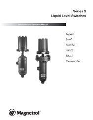
<strong>External</strong> <strong>Chambers</strong><br />
<strong>Sealed</strong> <strong>or</strong> <strong>Flanged</strong> <strong>Top</strong><br />
Technical<br />
Reference<br />
Manual
T A B L E O F C O N T E N T S<br />
Design Construction Comparison...................................................................................................................................2<br />
Dimensional Inf<strong>or</strong>mation<br />
Head Flange Type ....................................................................................................................................................3<br />
Probe Length ...........................................................................................................................................................3<br />
Physical Specifications...................................................................................................................................................4<br />
Model Number............................................................................................................................................................4-5<br />
Dimensional Specifications<br />
Slip-On <strong>Flanged</strong> Chamber Design - Commercial Construction .................................................................................6<br />
Slip-On <strong>Flanged</strong> Chamber Design - ANSI B31.3 Construction..................................................................................7<br />
Slip-On <strong>Flanged</strong> Chamber Design - ANSI B31.1 Construction..................................................................................7<br />
Weldneck <strong>Flanged</strong> Chamber Design - Commercial Construction..............................................................................8<br />
Weldneck <strong>Flanged</strong> Chamber Design - ANSI B31.3 Construction ..............................................................................9<br />
Weldneck <strong>Flanged</strong> Chamber Design - ANSI B31.1 Construction.......................................................................10-11<br />
<strong>Sealed</strong> Chamber Design - Commercial Construction..............................................................................................12<br />
<strong>Sealed</strong> Chamber Design - ANSI B31.3 Construction ..............................................................................................13<br />
<strong>Sealed</strong> Chamber Design - ANSI B31.1 Construction ..............................................................................................14<br />
D E S I G N C O N S T R U C T I O N C O M P A R I S O N<br />
2<br />
Comm B31.3 B31.1 NACE<br />
ASME grade and NACE listed materials • • •<br />
Certificate of Conf<strong>or</strong>mance on materials • • •<br />
Slip-on head and process flanges ➀<br />
• ≤1500# ➁ ≤300# •<br />
Weld neck head and slip-on process flanges ➀<br />
3" 1500#<br />
Weld neck head and process flanges 5000 psi ≥600#<br />
Pipe to pipe branch connections ≤600# ≤600#<br />
Bonney type fittings ≥900# • • ≥900#<br />
ASME Section IX welding procedures •<br />
Welding by ASME qualified welders per ASME Section IX procedures • • •<br />
Full penetration chamber branch welds • •<br />
Full penetration circumferential welds<br />
➂<br />
≥1500# ≥600#<br />
100% visual inspection of circumferential welds f<strong>or</strong> full penetration ≥1500# ➂<br />
≥600#<br />
Hydrostatic test at 1.5 × rated pressure • •<br />
Certified ten minute hydrostatic test at 1.5 × rated pressure • •<br />
Five percent radiographic examination of full penetration circumferential welds •<br />
Post weld heat treatment CS<br />
Annealing, if required f<strong>or</strong> hardness SS<br />
Hardness testing of welds and adjacent heat affected zones •<br />
<strong>Flanged</strong> <strong>or</strong> sealed chambers • • • •<br />
Stress limits per design code • •<br />
➀ Unless weldneck process flanges are specified in model number<br />
➁ Except 3" 1500# cage<br />
➂ Except 2" 1500# cage
D I M E N S I O N A L I N F O R M A T I O N<br />
H E A D F L A N G E T Y P E<br />
Design Standard Chamber Rating<br />
(third digit) (fifth digit)<br />
A<br />
Measuring<br />
Range<br />
150# (A)<br />
300# (B)<br />
Commercial 600# (C)<br />
(1, 5) 900# (D)<br />
1500# (E)<br />
5000 psi (F)<br />
150# (A)<br />
300# (B)<br />
Process Connection Type (seventh digit)<br />
NPT Socket Weld Slip-on RF Weldneck RF Weldneck RTJ<br />
(A, G) (B, H) (D, K) (E, L) (F, M)<br />
Slip-on raised face<br />
ASME B31.3 600# (C) Weldneck raised face<br />
(4, 7) 900# (D)<br />
1500# (E)<br />
*<br />
Weldneck raised face<br />
5000 psi (F) n/a<br />
150# (A)<br />
300# (B)<br />
ASME B31.1 600# (C)<br />
(3) 900# (D)<br />
1500# (E)<br />
5000 psi (F)<br />
Slip-on raised face<br />
Weldneck raised face n/a<br />
* 1500# ASME B31.3 will have a slip-on head flange on 2" cage and weldneck head flange on 3" cage<br />
P R O B E L E N G T H<br />
If utilizing a sealed top chamber, go to pages 13 & 14 f<strong>or</strong> ‘A’ dimension.<br />
To properly size your sensing element when mounting in a flange top chamber, it is necessary to determine the dimension from<br />
the face of the head flange to the centerline of the upper process connection. To determine this dimension:<br />
1. Use the third, fifth & seventh digits of your chamber model number and the above chart to verify the type of head flange on<br />
your chamber.<br />
2. On pages 6–12, locate the ‘A’ dimension of your chamber acc<strong>or</strong>ding to the chamber pressure rating, head flange type, design<br />
standard, chamber size & process connection size.<br />
3. Go to the f<strong>or</strong>mulas on page 4 f<strong>or</strong> probe <strong>or</strong> cable lengths. Using your ‘A’ dimension and measuring range (customer<br />
designated), determine your required probe length.<br />
A<br />
Measuring<br />
Range<br />
1" NPT drain<br />
<strong>Sealed</strong> Chamber Slip-on head flange Weldneck head flange<br />
A<br />
Measuring<br />
Range<br />
1" NPT drain<br />
3
P H Y S I C A L S P E C I F I C A T I O N S<br />
Measuring span length From 12 to 240 inches (30-610 cm)<br />
Eclipse probe length ➀<br />
sealed cage Measuring range ➁ + A + 5 inches (13 cm) (rounded down to nearest inch)<br />
flanged cage<br />
Kotron probe length ➂<br />
Measuring range ➁ + A + 6 inches (15 cm) (rounded down to nearest inch)<br />
sealed cage Measuring range ➁ + A + 3 inches (7 cm) (rounded down to nearest inch)<br />
flanged cage Measuring range ➁ + A + 4 inches (10 cm) (rounded down to nearest inch)<br />
Displacer cable length (min.) ➃➄ Measuring range ➁ + A + 6 inches (15 cm) (rounded up to nearest foot)<br />
Materials of Construction Carbon steel <strong>or</strong> 316 stainless steel<br />
(head flange bolting ASTM A193 GrB7 regardless of chamber material)<br />
Sens<strong>or</strong> Connections<br />
3 ⁄4" <strong>or</strong> 2" NPT, 2" <strong>or</strong> 3" flange from 150# to 2500# ANSI ➅<br />
Process Connection Sizes<br />
3 1 ⁄4", 1", 1 ⁄2" <strong>or</strong> 2"<br />
Process Connection Ratings 150#, 300#,600#, 900#, 1500# <strong>or</strong> 2500# ANSI ➅<br />
Process Connection Types threaded, socketweld, slip-on RF flanges,<br />
weldneck RF flanges, weldneck RTJ flanges<br />
Connection Configurations Side-side, side-bottom<br />
Process Pressures Up to 5000 psi (345 bar)<br />
Process Temperatures Up to +750° F (+399° C)<br />
4<br />
➀ See bulletin 57-101 f<strong>or</strong> Eclipse transmitter and probe part numbers.<br />
➁ Measuring range is last three digits of chamber model number.<br />
➂ See bulletin 50-125 f<strong>or</strong> Kotron probe part numbers.<br />
➃ See bulletin 45-115 f<strong>or</strong> top mounted displacer switch part numbers and allowable high level<br />
dimension with respect to face of mounting flange.<br />
➄ Must be used in 3" flanged cage.<br />
➅ Maximum pressure rating of cage with 2500# flanges is 5000 psi @ 100° F (345 bar @ 38° C).<br />
M O D E L N U M B E R<br />
MOUNTING<br />
S <strong>Sealed</strong> external chamber (NPT sens<strong>or</strong> connection)<br />
F <strong>Flanged</strong> top external chamber<br />
2 2 inch ➆ If sealed chamber, 3 NOMINAL CHAMBER DIAMETER<br />
⁄4" NPT sens<strong>or</strong> connection If flanged chamber, flanged sens<strong>or</strong> connection same size as chamber<br />
3 3 inch If sealed chamber, 2" NPT sens<strong>or</strong> connection If flanged chamber, flanged sens<strong>or</strong> connection same size as chamber<br />
➆ Displacer switches require 3" cage.<br />
DESIGN STANDARD<br />
1 Commercial Construction<br />
3 ASME B31.1 Certified ➇➈<br />
4 ASME B31.3 Certified ➇<br />
5 Commercial Construction and NACE certified ➇<br />
7 ASME B31.3 Certified and NACE certified ➇<br />
➇ Level switch/transmitter must also be specified to required code, if applicable.<br />
➈ ASME B31.1, 5000 psi chambers not available in carbon steel.
M O D E L N U M B E R C O N T I N U E D<br />
MATERIALS OF CONSTRUCTION ➉<br />
1 Carbon Steel, measuring range in inches ➈<br />
4 316/316L Stainless Steel, measuring range in inches<br />
➉ Process connection materials will match chamber materials<br />
CHAMBER RATING 11<br />
A 150# ANSI class<br />
B 300# ANSI class<br />
C 600# ANSI class<br />
D 900# ANSI class<br />
E 1500# ANSI class<br />
F 5000 psi (process flanges will be 2500# ANSI)<br />
11 Process flange, if applicable, will match chamber rating, except as indicated<br />
3 1 ⁄4"<br />
2 1"<br />
3 11 PROCESS CONNECTION SIZE<br />
⁄2"<br />
4 2"<br />
PROCESS CONNECTIONTYPEAND CONFIGURATION 12<br />
Side/Side Configurations Head Flange Type<br />
A NPT<br />
B SW Slip-on <strong>or</strong> weldneck<br />
D Slip-on RF Flange 14<br />
E<br />
F<br />
Weldneck RF Flange<br />
Weldneck RJ Flange<br />
Chamber rating codes A, B & C only<br />
Chamber rating codes C, D, E & F only<br />
Weldneck<br />
G NPT<br />
Side/Bottom Configurations<br />
H SW Slip-on <strong>or</strong> weldneck<br />
K Slip-on RF Flange<br />
L Weldneck RF Flange Chamber rating codes A, B & C only<br />
M Weldneck RJ Flange Chamber rating codes C, D, E & F only<br />
12<br />
13<br />
14<br />
14<br />
Process connection materials will match chamber materials<br />
See page 3 to determine type of head flange<br />
Cannot use slip-on flanges on 2" <strong>or</strong> 3", 5000 psi f<strong>or</strong> B31.3, n<strong>or</strong> on 2" <strong>or</strong> 3", ≥600# f<strong>or</strong> B31.1<br />
MEASURING RANGE<br />
12 to 240 inches<br />
Example: 12 inches = 012<br />
Weldneck<br />
13<br />
13<br />
5
D I M E N S I O N A L S P E C I F I C A T I O N S<br />
S L I P - O N F L A N G E D C H A M B E R D E S I G N<br />
COMMERCIAL CONSTRUCTION,2" CHAMBER (Models F21 and F25)<br />
6<br />
Process Conn. A B C D<br />
Connection Size 150# 300# 600# 900# 1500# 5000 psi All All 150# 300# 600# 900# 1500# 5000 psi<br />
NPT<br />
SW<br />
Slip-on Flg<br />
3 ⁄4" 2.03 2.31 2.31<br />
1"<br />
1<br />
6.00 6.50 8.50<br />
7.32 7.32 2.18 2.56 2.81<br />
1 ⁄2" 2.22 2.63 2.94<br />
2" 7.50 9.50 5.26 5.26 5.26<br />
3 ⁄4" 2.31 2.31 2.31<br />
1"<br />
1<br />
6.00 6.50 8.50<br />
7.32 7.32 2.28 2.56 2.81<br />
1 ⁄2" 2.10 2.63 2.94<br />
2" 7.50 8.12 5.07 5.07 5.07<br />
3 ⁄4" 5.87 5.87 7.25 7.87<br />
1"<br />
1<br />
6.00 6.50 8.50<br />
7.32 9.75 6.00 6.00 7.37 8.12<br />
1 ⁄2" 6.12 6.50 8.00 9.75<br />
2" 7.50 7.00 6.00 7.00 8.50 10.50<br />
COMMERCIAL CONSTRUCTION,3" CHAMBER (Models F31 and F35)<br />
Process Conn. A B C D<br />
Connection Size 150# 300# 600# 900# 1500# 5000 psi All All 150# 300# 600# 900# 1500# 5000 psi<br />
3 ⁄4" 2.69 2.87 2.87<br />
NPT<br />
1"<br />
1<br />
6.00 6.50 8.50 7.32 7.50<br />
2.87 3.12 3.37<br />
1 ⁄2" 2.94 3.19 3.50<br />
2" 2.88 3.31 3.87<br />
SW<br />
Slip-on Flg<br />
3 ⁄4" 2.97 2.87 2.87<br />
1"<br />
1<br />
6.00 6.50 8.50 7.32 7.50<br />
3.00 3.12 3.37<br />
1 ⁄2" 3.00 3.19 3.50<br />
2" 3.10 3.31 3.87 3.87<br />
3 ⁄4" 6.75<br />
1"<br />
1<br />
6.00 6.50 8.50 7.32 9.75<br />
6.81<br />
6.25 6.75 8.00<br />
1 ⁄2" 7.00<br />
2" 7.13<br />
D<br />
A<br />
Measuring<br />
Range<br />
Slip-on flanged chamber<br />
with side/bottom flanged connections<br />
C<br />
D<br />
Slip-on flanged chamber<br />
with side/bottom NPT <strong>or</strong> SW connections<br />
A<br />
Measuring<br />
Range<br />
C<br />
1" NPT drain<br />
D<br />
A<br />
Measuring<br />
Range<br />
Slip-on flanged chamber<br />
with side/side connections<br />
B
D I M E N S I O N A L S P E C I F I C A T I O N S<br />
S L I P - O N F L A N G E D C H A M B E R D E S I G N<br />
ANSI B31.3 CONSTRUCTION,2" CHAMBERS (150 thru 1500# only – Models F24 and F27)<br />
Process Conn. A B C D<br />
Connection Size 150# 300# 600# 900# 1500# All All 150# 300# 600# 900# 1500#<br />
NPT<br />
SW<br />
Slip-on Flg<br />
3 ⁄4" 2.31 2.69<br />
1"<br />
1<br />
6.00 6.50<br />
8.00 8.00 2.56 2.81<br />
1 ⁄2" 2.63 2.94<br />
2" 8.18 9.50 5.26 5.26<br />
3 ⁄4" 2.31 2.69<br />
1"<br />
1<br />
6.00 6.50<br />
8.00 8.00 2.56 2.81<br />
1 ⁄2" 2.63 2.94<br />
2" 8.18 8.12 5.07 5.07<br />
3 ⁄4"<br />
1"<br />
1<br />
6.00 6.50<br />
8.00 10.50<br />
1 ⁄2"<br />
2" 8.18 7.00<br />
ANSI B31.3 CONSTRUCTION,3" CHAMBERS (150 thru 900# only – Models F34 and F37)<br />
5.00 5.25 5.75<br />
Process Conn. A B C D<br />
Connection Size 150# 300# 600# 900# All All 150# 300# 600# 900#<br />
NPT/SW<br />
Slip-on Flg<br />
3 ⁄4" 2.87<br />
1"<br />
1<br />
6.00 8.00 8.18<br />
3.12<br />
1 ⁄2" 3.19<br />
2" 3.31<br />
3 ⁄4"<br />
1"<br />
11 ⁄2"<br />
2"<br />
ANSI B31.1 CONSTRUCTION,2" CHAMBERS (150 and 300# only – Model F23)<br />
Process Conn. A B C D<br />
Connection Size All All All 150# 300#<br />
3 ⁄4" 2.31<br />
NPT<br />
1"<br />
1<br />
6.00<br />
8.00 8.00 2.56<br />
1 ⁄2" 2.63<br />
2" 8.18 9.50 5.26<br />
3 ⁄4" 2.31<br />
SW<br />
1"<br />
1<br />
6.00<br />
8.00 8.00 2.56<br />
1 ⁄2" 2.63<br />
2" 8.18 8.12 5.07<br />
Slip-on Flg<br />
3 ⁄4"<br />
1"<br />
1<br />
6.00<br />
8.00 10.50<br />
1 ⁄2"<br />
2" 8.18 7.00<br />
6.00 8.00 10.50 5.50 6.00 6.25<br />
5.00 5.25<br />
ANSI B31.1 CONSTRUCTION,3" CHAMBERS (150 and 300# only – Model F33)<br />
Process Conn. A B C D<br />
Connection Size All All All 150# 300#<br />
3 ⁄4" 2.87<br />
NPT<br />
1"<br />
1<br />
6.00 8.00 8.00<br />
3.12<br />
1 ⁄2" 3.19<br />
2" 3.31<br />
3 ⁄4" 2.87<br />
SW<br />
1"<br />
1<br />
6.00 8.00 8.00<br />
3.12<br />
1 ⁄2" 3.19<br />
2" 3.31<br />
Slip-on Flg<br />
3 ⁄4"<br />
1"<br />
11 ⁄2"<br />
2"<br />
6.00 8.00 10.50 5.50 6.00<br />
7
D I M E N S I O N A L S P E C I F I C A T I O N S<br />
W E L D N E C K F L A N G E D C H A M B E R D E S I G N<br />
COMMERCIAL CONSTRUCTION,2" CHAMBER (Models F21 and F25)<br />
8<br />
Process Conn. A B<br />
Connection Size 150# 300# 600# 900# 1500# 5000 psi 150# 300# 600# 900# 1500# 5000 psi<br />
Weldneck Flg<br />
3 ⁄4"<br />
1" 6.00 6.50 8.50 7.32<br />
1 1 ⁄2"<br />
2" 7.50 6.50 6.50 9.50 7.50 8.50 7.50<br />
Process Conn. C D<br />
Connection Size 150# 300# 600# 900# 1500# 5000 psi 150# 300# 600# 900# 1500# 5000 psi<br />
Weldneck Flg<br />
3 ⁄4" 5.69 5.88 5.88 4.94 5.31<br />
1" 12.50 13.00 13.50 5.75 6.00 6.00 5.25 6.31<br />
11 ⁄2" 5.81 6.06 6.12 5.81 7.69<br />
2" 9.18 9.56 10.68 11.68 5.06 5.31 5.44 6.56 7.56<br />
COMMERCIAL CONSTRUCTION,3" CHAMBER (Models F31 and F35)<br />
Process Conn. A B<br />
Connection Size 150# 300# 600# 900# 1500# 5000 psi 150# 300# 600# 900# 1500# 5000 psi<br />
Weldneck Flg<br />
3 ⁄4"<br />
1" 6.00<br />
6.50 8.50<br />
11 ⁄2" 7.50 9.50<br />
2" 6.00 7.00 7.50 9.50<br />
Process Conn. C D<br />
Connection Size 150# 300# 600# 900# 1500# 5000 psi 150# 300# 600# 900# 1500# 5000 psi<br />
3 ⁄4" 6.56 6.75 6.75 5.50 5.50 5.87<br />
Weldneck Flg<br />
1"<br />
1<br />
12.50 13.00 13.50<br />
6.56 6.81 6.81 5.81 5.81 6.87<br />
1 ⁄2" 6.69 6.94 7.00 6.37 6.37 8.25<br />
2" 6.76 7.01 7.14 7.37 8.05 9.05<br />
D<br />
A<br />
Measuring<br />
Range<br />
Weldneck flanged chamber with<br />
side/bottom flanged connections<br />
C<br />
D<br />
Weldneck flanged chamber with<br />
side/bottom NPT <strong>or</strong> SW connections<br />
A<br />
Measuring<br />
Range<br />
C<br />
7.32<br />
1" NPT drain<br />
D<br />
A<br />
Measuring<br />
Range<br />
Weldneck flanged chamber with<br />
side/side connections<br />
B
D I M E N S I O N A L S P E C I F I C A T I O N S<br />
W E L D N E C K F L A N G E D C H A M B E R D E S I G N<br />
ASME B31.3 CONSTRUCTION,2" CHAMBER (Models F24 and F27)<br />
Process Conn. A B<br />
Connection Size 150# 300# 600# 900# 1500# 5000 psi 150# 300# 600# 900# 1500# 5000 psi<br />
NPT<br />
SW<br />
Weldneck Flg<br />
3 ⁄4"<br />
1"<br />
1<br />
n/a<br />
8.50<br />
n/a<br />
8.00<br />
1 ⁄2"<br />
2" 9.50 8.18<br />
3 ⁄4"<br />
1"<br />
1<br />
n/a<br />
8.50<br />
n/a<br />
8.00<br />
1 ⁄2"<br />
2" 9.50 8.18<br />
3 ⁄4"<br />
1" 6.00 6.50 8.50 8.00 8.00<br />
1 1 ⁄2"<br />
2" 7.50 6.50 6.50 9.50 8.18 8.18<br />
Process Conn. C D<br />
Connection Size 150# 300# 600# 900# 1500# 5000 psi 150# 300# 600# 900# 1500# 5000 psi<br />
NPT<br />
3 ⁄4" 2.69<br />
1"<br />
1<br />
n/a<br />
8.00<br />
n/a<br />
2.81<br />
1 ⁄2" 2.94<br />
2" 8.50 5.26<br />
3 ⁄4" 2.69<br />
SW<br />
1"<br />
1<br />
n/a<br />
8.00<br />
n/a<br />
2.81<br />
1 ⁄2" 2.94<br />
2" 7.12 5.07<br />
3 ⁄4" 4.25 4.44 4.44 4.94 5.31/4.94 5.68<br />
Weldneck Flg 1" 12.50 13.00 13.50 14.50 4.56 4.81 4.81 5.25 5.69/5.25 6.31<br />
(cs/ss) 11 ⁄2" 5.00 5.25 5.31 5.81 6.56 7.69<br />
2" 9.18 9.56 10.68 11.68 5.06 5.31 5.44 6.56 6.56 7.56<br />
ASME B31.3 CONSTRUCTION,3" CHAMBER (Models F34 and F37)<br />
Process Conn. A B<br />
Connection Size 150# 300# 600# 900# 1500# 5000 psi 150# 300# 600# 900# 1500# 5000 psi<br />
NPT/SW<br />
Slip-on Flg<br />
Weldneck Flg<br />
3 ⁄4"<br />
1"<br />
11 ⁄2"<br />
2"<br />
3 ⁄4"<br />
1"<br />
11 ⁄2"<br />
2"<br />
3 ⁄4"<br />
6.50 8.50<br />
n/a n/a n/a 8.00<br />
7.50 9.50<br />
n/a<br />
1"<br />
1<br />
6.00<br />
1 ⁄2"<br />
2" 6.00 7.00<br />
6.50<br />
7.50<br />
6.50 8.50<br />
7.50 9.50<br />
n/a n/a 8.00 n/a<br />
Process Conn. C D<br />
Connection Size 150# 300# 600# 900# 1500# 5000 psi 150# 300# 600# 900# 1500# 5000 psi<br />
NPT/SW<br />
Slip-on Flg<br />
3 ⁄4" 2.87 3.25<br />
1"<br />
1<br />
n/a 8.00 n/a<br />
3.12 3.37<br />
1 ⁄2" 3.50 3.50<br />
2" 3.87 3.87<br />
3 ⁄4"<br />
1"<br />
11 ⁄2"<br />
2"<br />
n/a 10.50 n/a n/a 6.75 n/a<br />
3 ⁄4" 4.81 5.00 5.00 5.50 5.87/5.50 6.24<br />
Weldneck Flg<br />
(cs/ss)<br />
1"<br />
1<br />
12.50 13.00 13.50 14.50<br />
5.12 5.37 4.37 5.81 6.25/5.88 6.87<br />
1 ⁄2" 5.56 5.81 5.87 6.37 7.12 8.25<br />
2" 5.87 6.12 6.25 8.05/7.37 8.05 9.05<br />
8.00<br />
9
D I M E N S I O N A L S P E C I F I C A T I O N S<br />
W E L D N E C K F L A N G E D C H A M B E R D E S I G N<br />
ASME B31.1 CONSTRUCTION,2" CHAMBER (Model F23)<br />
10<br />
Process Conn. A B<br />
Connection Size 150# 300# 600# 900# 1500# 5000 psi ➀ 150# 300# 600# 900# 1500# 5000 psi ➀<br />
3 ⁄4"<br />
NPT<br />
(cs/ss)<br />
1"<br />
1<br />
n/a<br />
6.00<br />
6.50<br />
8.50<br />
n/a 8.00<br />
1 ⁄2"<br />
2" 7.50 6.50 9.50 8.18<br />
3 ⁄4"<br />
SW<br />
(cs/ss)<br />
1"<br />
1<br />
n/a<br />
6.00<br />
6.50<br />
8.50<br />
n/a<br />
8.00<br />
1 ⁄2"<br />
2" 7.50 6.50 9.50 8.18<br />
3 ⁄4"<br />
Weldneck Flg 1" 6.00 6.50 8.50 8.00<br />
(cs/ss) 1 1 ⁄2"<br />
2" 6.00/7.50 7.50 6.50 6.50 9.50 8.18<br />
Process Conn. C D<br />
Connection Size 150# 300# 600# 900# 1500# 5000 psi ➀ 150# 300# 600# 900# 1500# 5000 psi ➀<br />
3 ⁄4" 2.31 2.69/2.31 2.69<br />
NPT<br />
(cs/ss)<br />
1"<br />
1<br />
n/a<br />
8.00 8.00<br />
n/a<br />
2.56 2.81/2.56 2.81<br />
1 ⁄2" 2.63 2.94 2.94<br />
2" 9.50 8.50 5.26 5.26 5.26<br />
3 ⁄4" 2.31 2.69/2.31 2.69<br />
SW<br />
(cs/ss)<br />
1"<br />
1<br />
n/a<br />
8.00 8.00<br />
n/a<br />
2.56 2.81/2.56 2.81<br />
1 ⁄2" 2.63 2.94 2.94<br />
2" 8.12 7.12 5.07 5.07 5.07<br />
3 ⁄4" 4.25 4.44 4.44 4.94 5.31/4.94 5.68<br />
Weldneck Flg 1" 12.50 13.00 13.50 14.50 4.56 4.81 4.81 5.25 5.69/5.25 6.31<br />
(cs/ss) 11 ⁄2" 5.00 5.25 5.31 5.81 6.56 7.69<br />
2" 9.18 9.56 10.68 11.68 5.06 5.31 5.44 6.56 6.56 7.56<br />
➀ Available in stainless steel construction only.
D I M E N S I O N A L S P E C I F I C A T I O N S<br />
W E L D N E C K F L A N G E D C H A M B E R D E S I G N<br />
ASME B31.1 CONSTRUCTION,3" CHAMBER (Model F33)<br />
Process Conn. A B<br />
Connection Size 150# 300# 600# 900# 1500# 5000 psi ➀ 150# 300# 600# 900# 1500# 5000 psi ➀<br />
NPT<br />
SW<br />
Weldneck Flg<br />
3 ⁄4"<br />
1"<br />
1<br />
n/a<br />
6.00<br />
1 ⁄2"<br />
2" 7.00<br />
3 ⁄4"<br />
1"<br />
1<br />
n/a<br />
6.00<br />
1 ⁄2"<br />
2" 7.00<br />
3 ⁄4"<br />
1"<br />
1<br />
6.00<br />
6.00<br />
1 ⁄2"<br />
2" 7.00<br />
6.50 8.50<br />
7.50 9.50<br />
6.50 8.50<br />
7.50 9.50<br />
6.50 8.50<br />
7.50 9.50<br />
n/a 8.00<br />
n/a 8.00<br />
Process Conn. C D<br />
Connection Size 150# 300# 600# 900# 1500# 5000 psi ➀ 150# 300# 600# 900# 1500# 5000 psi ➀<br />
3 ⁄4" 2.87 2.87 3.25<br />
NPT<br />
1"<br />
1<br />
n/a n/a n/a<br />
3.12 3.12 3.37<br />
1 ⁄2" 3.19 3.19 3.50<br />
2"<br />
3 ⁄4"<br />
3.31<br />
2.87<br />
3.31<br />
2.87<br />
3.87<br />
3.25<br />
SW<br />
1"<br />
1<br />
n/a n/a n/a<br />
3.12 3.12 3.37<br />
1 ⁄2" 3.19 3.19 3.50<br />
2" 3.31 3.87 3.87<br />
3 ⁄4" 4.81 5.00 5.00 5.50 5.87/5.50 6.24<br />
Weldneck Flg<br />
(cs/ss)<br />
1"<br />
1<br />
12.50 13.00 13.50 14.50<br />
5.12 5.37 5.37 5.81 6.25/5.88 6.87<br />
1 8.00<br />
⁄2" 5.56 5.81 5.87 6.37 7.12 8.25<br />
2" 5.87 6.12 6.25 8.05/7.37 8.05 9.05<br />
➀ Available in stainless steel construction only.<br />
D<br />
A<br />
Measuring<br />
Range<br />
Weldneck flanged chamber with<br />
side/bottom flanged connections<br />
C<br />
D<br />
Weldneck flanged chamber with<br />
side/bottom NPT <strong>or</strong> SW connections<br />
A<br />
Measuring<br />
Range<br />
C<br />
8.00<br />
1" NPT drain<br />
D<br />
A<br />
Measuring<br />
Range<br />
Weldneck flanged chamber with<br />
side/side connections<br />
B<br />
11
D I M E N S I O N A L S P E C I F I C A T I O N S<br />
S E A L E D C H A M B E R D E S I G N<br />
COMMERCIAL CONSTRUCTION,2" CHAMBER (Models S21 and S25)<br />
12<br />
Process Conn. A B C D<br />
Connection Size All All 150# 300# 600# 900# 1500# 5000 psi 150# 300# 600# 900# 1500# 5000 psi<br />
NPT<br />
SW<br />
Slip-on Flg<br />
Weldneck Flg<br />
3 ⁄4" 2.03 2.31 2.31<br />
1"<br />
1<br />
7.00 7.50<br />
7.50 2.18 2.56 2.81<br />
1 ⁄2" 2.22 2.63 2.94<br />
2" 9.50 5.26 5.26 5.26<br />
3 ⁄4" 2.31 2.31 2.31<br />
1"<br />
1<br />
7.00 7.50<br />
7.50 2.28 2.56 2.81<br />
1 ⁄2" 2.10 2.63 2.94<br />
2" 8.12 5.07 5.07 5.07<br />
3 ⁄4" 5.88 5.88 7.25 7.87<br />
1"<br />
1<br />
7.00 7.50<br />
9.93 6.00 6.00 7.37 8.12<br />
1 ⁄2" 6.12 6.50 8.00 9.75<br />
2" 7.00 6.00 7.00 8.50 10.50<br />
3 ⁄4" 5.69 5.88 5.88 4.94 5.31<br />
1"<br />
1<br />
7.00 7.50<br />
12.68 13.18 13.68 5.75 6.00 6.00 5.25 6.31<br />
1 ⁄2" 5.81 6.06 6.12 5.81 7.69<br />
2" 9.18 9.43 9.56 10.68 11.68 5.06 5.31 5.44 6.56 7.56<br />
COMMERCIAL CONSTRUCTION,3" CHAMBER (Models S31 and S35)<br />
Process Conn. A B C D<br />
Connection Size All All 150# 300# 600# 900# 1500# 5000 psi 150# 300# 600# 900# 1500# 5000 psi<br />
3 ⁄4" 2.69 2.87 2.87<br />
NPT<br />
1"<br />
1<br />
7.00 7.50 7.50<br />
2.87 3.12 3.37<br />
1 ⁄2" 2.94 3.19 3.50<br />
2" 2.88 3.31 3.87<br />
3 ⁄4" 2.97 2.87 2.87<br />
SW<br />
1"<br />
1<br />
7.00 7.50 7.50<br />
3.00 3.12 3.37<br />
1 ⁄2" 3.00 3.19 3.50<br />
2" 3.10 3.87 3.87<br />
3 ⁄4" 6.75<br />
Slip-on Flg<br />
1"<br />
1<br />
7.00 7.50 9.93<br />
6.81<br />
6.25 6.75 8.00<br />
1 ⁄2" 7.00<br />
2" 7.13<br />
Weldneck Flg<br />
3 ⁄4" 6.56 6.75 6.75 5.50 5.50 5.87<br />
1"<br />
1<br />
7.00 7.50 12.68 13.18 13.68<br />
6.56 6.81 6.81 5.81 5.81 6.87<br />
1 ⁄2" 6.69 6.94 7.00 6.37 6.37 8.25<br />
2" 6.75 7.00 7.13 7.37 8.05 9.05
D I M E N S I O N A L S P E C I F I C A T I O N S<br />
S E A L E D C H A M B E R D E S I G N<br />
ASME B31.3 CONSTRUCTION,2" CHAMBER (Models S24 and S27)<br />
Process Conn. A B C D<br />
Connection Size All All 150# 300# 600# 900# 1500# 5000 psi 150# 300# 600# 900# 1500# 5000 psi<br />
NPT<br />
SW<br />
Slip-on Flg<br />
3 ⁄4" 2.31 2.69<br />
1"<br />
1<br />
7.68 8.18<br />
8.18 2.56 2.81<br />
1 ⁄2" 2.63 2.94<br />
2" 9.50 5.26 5.26<br />
3 ⁄4" 2.31 2.69<br />
1"<br />
1<br />
7.68 8.18 8.18<br />
2.56 2.81<br />
1 ⁄2" 2.63 2.94<br />
2" 5.07 5.07<br />
3 ⁄4"<br />
1"<br />
1<br />
7.68 8.18<br />
9.93<br />
1 ⁄2"<br />
2" 7.00<br />
n/a 5.00 5.25 5.75 n/a<br />
3 ⁄4" 4.25 4.44 4.44 4.94 5.31/4.94 5.68<br />
Weldneck Flg<br />
(cs/ss)<br />
1"<br />
1<br />
7.68 8.18<br />
12.68 13.18 13.68 14.68 4.56 4.81 4.81 5.25 5.69/5.25 6.31<br />
1 ⁄2" 5.00 5.25 5.31 5.81 6.56 7.69<br />
2" 9.18 9.43 9.56 10.68 11.68 5.06 5.31 5.44 6.56 6.56 7.56<br />
ASME B31.3 CONSTRUCTION,3" CHAMBER (Models S34 and S37)<br />
Process Conn. A B C D<br />
Connection Size All All 150# 300# 600# 900# 1500# 5000 psi 150# 300# 600# 900# 1500# 5000 psi<br />
NPT<br />
SW<br />
Slip-on Flg<br />
3 ⁄4" 2.87 2.87 2.87<br />
1"<br />
1<br />
7.68 8.18 8.18<br />
3.12 3.12 3.37<br />
1 ⁄2" 3.19 3.50 3.50<br />
2" 3.31 3.87 3.87<br />
3 ⁄4" 2.87 2.87 2.87<br />
1"<br />
1<br />
7.68 8.18 8.18<br />
3.12 3.12 3.37<br />
1 ⁄2" 3.19 3.50 3.50<br />
2" 3.31 3.87 3.87<br />
3 ⁄4"<br />
1"<br />
11 ⁄2"<br />
2"<br />
7.68 8.18 10.68 n/a 5.50 6.00 6.25 6.75 n/a<br />
3 ⁄4" 4.81 5.00 5.00 5.50 5.87/5.50 6.24<br />
Weldneck Flg<br />
(cs/ss)<br />
1"<br />
1<br />
7.68 8.18 12.68 13.18 13.68 14.68<br />
5.12 5.37 5.37 5.81 6.25/5.88 6.87<br />
1 ⁄2" 5.56 5.81 5.87 6.37 7.12 8.25<br />
2" 5.87 6.12 6.25 8.05/7.37 8.05 9.05<br />
D<br />
A<br />
Measuring<br />
Range<br />
<strong>Sealed</strong> chamber with<br />
side/bottom flanged connections<br />
C<br />
D<br />
<strong>Sealed</strong> chamber with<br />
side/bottom NPT <strong>or</strong> SW connections<br />
A<br />
Measuring<br />
Range<br />
C<br />
1" NPT drain<br />
D<br />
A<br />
Measuring<br />
Range<br />
<strong>Sealed</strong> chamber with<br />
side/side connections<br />
B<br />
13
D I M E N S I O N A L S P E C I F I C A T I O N S<br />
S E A L E D C H A M B E R D E S I G N<br />
ASME B31.1 CONSTRUCTION,2" CHAMBER (Model S23)<br />
Process Conn. A B C D<br />
Connection Size All All 150# 300# 600# 900# 1500# 5000psi➀ 150# 300# 600# 900# 1500# 5000psi➀<br />
14<br />
3 ⁄4" 2.31 2.69/2.31 2.69<br />
NPT<br />
(cs/ss)<br />
1"<br />
1<br />
7.68 8.18<br />
8.18 2.56 2.81/2.56 2.81<br />
1 ⁄2" 2.63 2.94 2.94<br />
2" 9.50 5.26 5.26 5.26<br />
3 ⁄4" 2.31 2.69/2.31 2.69<br />
SW<br />
(cs/ss)<br />
1"<br />
1<br />
7.68 8.18 8.18<br />
2.56 2.81/2.56 2.81<br />
1 ⁄2" 2.63 2.94 2.94<br />
2" 5.07 5.07 5.07<br />
Slip-on Flg<br />
3 ⁄4"<br />
1"<br />
1<br />
7.68 8.18<br />
9.93<br />
1 ⁄2"<br />
2" 7.00<br />
D<br />
A<br />
Measuring<br />
Range<br />
<strong>Sealed</strong> chamber with<br />
side/bottom flanged connections<br />
C<br />
<strong>Sealed</strong> chamber with<br />
side/bottom NPT <strong>or</strong> SW connections<br />
n/a 5.00 5.25 n/a<br />
3 ⁄4" 4.25 4.44 4.44 4.94 5.31/4.94 5.68<br />
Weldneck Flg<br />
(cs/ss)<br />
1"<br />
1<br />
7.68 8.18<br />
12.68 13.18 13.68 4.56 4.81 4.81 5.25 5.69/5.25 6.31<br />
1 ⁄2" 5.00 5.25 5.31 5.81 6.56 7.69<br />
2" 9.18 9.43 9.56 10.68 5.06 5.31 5.44 6.56 6.56 7.56<br />
ASME B31.1 CONSTRUCTION,3" CHAMBER (Model S33)<br />
Process Conn. A B C D<br />
Connection Size All All 150# 300# 600# 900# 1500# 5000psi➀ 150# 300# 600# 900# 1500# 5000psi➀<br />
3 ⁄4" 2.87 2.87 3.25/2.87 3.25<br />
NPT<br />
(cs/ss)<br />
1"<br />
1<br />
7.68 8.18 8.18<br />
3.12 3.12 3.37/3.12 3.37<br />
1 ⁄2" 3.19 3.19 3.50 3.50<br />
2" 3.31 3.31 3.87 3.87<br />
3 ⁄4" 2.87 2.87 3.25/2.87 3.25<br />
SW<br />
(cs/ss)<br />
1"<br />
1<br />
7.68 8.18 8.18<br />
3.12 3.12 3.37/3.12 3.37<br />
1 ⁄2" 3.19 3.19 3.50 3.50<br />
2" 3.31 3.87/3.31 3.87 3.87<br />
Slip-on Flg<br />
3 ⁄4"<br />
1"<br />
11 ⁄2"<br />
2"<br />
7.68 8.18 10.68 n/a 5.50 6.00 n/a<br />
3 ⁄4" 4.81 5.00 5.00 5.50 5.87/5.50 6.24<br />
Weldneck Flg<br />
(cs/ss)<br />
1"<br />
1<br />
7.68 8.18 12.68 13.18 13.68 14.68<br />
5.12 5.37 5.37 5.81 6.25/5.88 6.87<br />
1 ⁄2" 5.56 5.81 5.87 6.37 7.12 8.25<br />
2" 5.87 6.12 6.25 8.05/7.37 8.05 9.05<br />
➀ Available in stainless steel construction only.<br />
D<br />
A<br />
Measuring<br />
Range<br />
C<br />
1" NPT drain<br />
D<br />
A<br />
Measuring<br />
Range<br />
<strong>Sealed</strong> chamber with<br />
side/side connections<br />
B
Warranty<br />
All <strong>Magnetrol</strong> mechanical level equipment is warranted free of<br />
defects in materials <strong>or</strong> w<strong>or</strong>kmanship f<strong>or</strong> five full years from the<br />
date of <strong>or</strong>iginal fact<strong>or</strong>y shipment.<br />
If returned within the warranty period; and, upon fact<strong>or</strong>y<br />
inspection of the equipment, the cause of the claim is<br />
determined to be covered under the warranty; then, <strong>Magnetrol</strong><br />
will repair <strong>or</strong> replace the equipment at no cost to the purchaser<br />
(<strong>or</strong> owner) other than transp<strong>or</strong>tation.<br />
<strong>Magnetrol</strong> shall not be liable f<strong>or</strong> misapplication, lab<strong>or</strong> claims,<br />
direct <strong>or</strong> consequential damage <strong>or</strong> expense arising from the<br />
installation <strong>or</strong> use of equipment. There are no other warranties<br />
expressed <strong>or</strong> implied, except special written warranties covering<br />
some <strong>Magnetrol</strong> products.<br />
Service Policy<br />
Owners of <strong>Magnetrol</strong> controls may request the return of a control<br />
<strong>or</strong> any part of a control f<strong>or</strong> complete rebuilding <strong>or</strong> replacement.<br />
They will be rebuilt <strong>or</strong> replaced promptly. Controls<br />
returned under our service policy must be returned by Prepaid<br />
transp<strong>or</strong>tation. <strong>Magnetrol</strong> will repair <strong>or</strong> replace the control at<br />
no cost to the purchaser (<strong>or</strong> owner) other than transp<strong>or</strong>tation if:<br />
1. Returned within the warranty period; and<br />
2. The fact<strong>or</strong>y inspection finds the cause of the claim to be<br />
covered under the warranty.<br />
If the trouble is the result of conditions beyond our control; <strong>or</strong>,<br />
is NOT covered by the warranty, there will be charges f<strong>or</strong> lab<strong>or</strong><br />
and the parts required to rebuild <strong>or</strong> replace the equipment.<br />
In some cases it may be expedient to ship replacement parts; <strong>or</strong>,<br />
in extreme cases a complete new control, to replace the <strong>or</strong>iginal<br />
equipment bef<strong>or</strong>e it is returned. If this is desired, notify<br />
the fact<strong>or</strong>y of both the model and serial numbers of the control<br />
to be replaced. In such cases, credit f<strong>or</strong> the materials<br />
returned will be determined on the basis of the applicability of<br />
our warranty.<br />
No claims f<strong>or</strong> misapplication, lab<strong>or</strong>, direct <strong>or</strong> consequential<br />
damage will be allowed.<br />
Low Voltage Directive<br />
F<strong>or</strong> use in Categ<strong>or</strong>y II installations. If equipment is used in a<br />
manner not specified by manufacturer, protection provided by<br />
equipment may be impaired.<br />
5300 Belmont Road • Downers Grove, Illinois 60515-4499 • 630-969-4000 • Fax 630-969-9489 • www.magnetrol.com<br />
145 Jardin Drive, Units 1 & 2 • Conc<strong>or</strong>d, Ontario Canada L4K 1X7 • 905-738-9600 • Fax 905-738-1306<br />
Heikensstraat 6 • B 9240 Zele, Belgium • 052 45.11.11 • Fax 052 45.09.93<br />
Regent Business Ctr., Jubilee Rd. • Burgess Hill, Sussex RH15 9TL U.K. • 01444-871313 • Fax 01444-871317<br />
Copyright © 2009 <strong>Magnetrol</strong> International, Inc<strong>or</strong>p<strong>or</strong>ated. All rights reserved. Printed in the USA.<br />
Perf<strong>or</strong>mance specifications are effective with date of issue and are subject to change without notice.<br />
Quality Assurance<br />
The quality assurance system in place at<br />
<strong>Magnetrol</strong> guarantees the highest level<br />
of quality throughout the company.<br />
<strong>Magnetrol</strong> is committed to providing full<br />
customer satisfaction both in quality<br />
products and quality service.<br />
<strong>Magnetrol</strong>’s quality assurance system is registered to ISO 9001<br />
affirming its commitment to known international quality<br />
standards providing the strongest assurance of product/service<br />
quality available.<br />
Return Material Procedure<br />
So that we may efficiently process any materials that are<br />
returned, it is essential that a “Return Material Auth<strong>or</strong>ization”<br />
(RMA) number be obtained from the fact<strong>or</strong>y, pri<strong>or</strong> to the<br />
material's return. This is available through <strong>Magnetrol</strong>’s local<br />
representative <strong>or</strong> by contacting the fact<strong>or</strong>y. Please supply the<br />
following inf<strong>or</strong>mation:<br />
1. Company Name<br />
2. Description of Material<br />
3. Serial Number<br />
4. Reason f<strong>or</strong> Return<br />
5. Application<br />
Any unit that was used in a process must be properly cleaned<br />
in acc<strong>or</strong>dance with OSHA standards, bef<strong>or</strong>e it is returned to<br />
the fact<strong>or</strong>y.<br />
A Material Safety Data Sheet (MSDS) must accompany material<br />
that was used in any media.<br />
All shipments returned to the fact<strong>or</strong>y must be by prepaid<br />
transp<strong>or</strong>tation.<br />
All replacements will be shipped F.O.B. fact<strong>or</strong>y.<br />
Notice of Trademark, Copyright, and Limitations<br />
Eclipse and Kotron are tradenames of <strong>Magnetrol</strong><br />
International, Inc<strong>or</strong>p<strong>or</strong>ated.<br />
© 2009 <strong>Magnetrol</strong> International, Inc<strong>or</strong>p<strong>or</strong>ated.<br />
All rights reserved.<br />
<strong>Magnetrol</strong> reserves the right to make changes to the<br />
product described in this manual at any time without notice.<br />
<strong>Magnetrol</strong> makes no warranty with respect to the accuracy of<br />
the inf<strong>or</strong>mation in this manual.<br />
BULLETIN: <strong>41</strong>-<strong>640</strong>.2<br />
EFFECTIVE: July 2003<br />
SUPERSEDES: October 2001