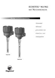
Instruction Manual - Magnetrol International
Instruction Manual - Magnetrol International
Instruction Manual - Magnetrol International

Create successful ePaper yourself
Turn your PDF publications into a flip-book with our unique Google optimized e-Paper software.
MODEL IDENTIFICATION<br />
A complete measuring system consists of:<br />
1. Code for side mounted models (each unit can be factory calibrated when specific level differentials are specified separately).<br />
2. Code for modified models or adders: put an "X" in front of the closest matching order code and specify the modifications/<br />
adders separately<br />
eg. XT62-AG3A-AAP X = with material certification EN 10204 / DIN 50049-3.1.B<br />
3. OPTION: External cage: consult factory for model description.<br />
1. Code for T62/T67 side mounted float level switch<br />
BASIC MODEL NUMBER1<br />
– Single switch model<br />
2<br />
T 6 2 down to S.G. 0,50 up to 34,5 bar (500 psi)<br />
– Dual switch model<br />
T 6 7 down to S.G. 0,50 up to 34,5 bar (500 psi)<br />
MATERIALS OF CONSTRUCTION<br />
Code<br />
A<br />
B<br />
PROCESS CONNECTION<br />
– threaded<br />
F 2 3" NPT<br />
– ANSI flanges<br />
G 3 3" 150 lbs ANSI RF<br />
G 4 3" 300 lbs ANSI RF<br />
H 3 4" 150 lbs ANSI RF<br />
H 4 4" 300 lbs ANSI RF<br />
.– DIN flanges<br />
7 F DN 80, PN 16 DIN 2527 form C<br />
7 G DN 80, PN 25/40 DIN 2527 form C<br />
8 F DN 100, PN 16 DIN 2527 form C<br />
8 G DN 100, PN 25/40 DIN 2527 form C<br />
➀ All floats can be screwed to float stem from inside of vessel in case the float cannot pass through the nozzle.<br />
SWITCH MECHANISM & ENCLOSURE - for T62 units (see page 3)<br />
- for T67 units (see page 4)<br />
- for pneumatic switch mechanisms (see table below)<br />
T 6 complete code for T62/T67 side mounted float level switch<br />
Select pneumatic switch mechanism & enclosure - for T62/T64 models<br />
Pneumatic switch type<br />
Series J<br />
(open air)<br />
Series K<br />
(closed circuit)<br />
Cage & process<br />
connection material<br />
Carbon steel<br />
D 316/316L (1.4401/1.4404)<br />
Max supply pressure<br />
bar (psi)<br />
Max liquid temperature<br />
°C (°F)<br />
Float and trim Magnetic sleeve<br />
316 SST (1.4401)<br />
Bleed orifice Ø<br />
mm (inches)<br />
400 series SST<br />
316 SST (1.4401)<br />
FLOAT AND STEM LENGTH<br />
Stem length versus min S.G.<br />
Float size<br />
mm (inches) ➀<br />
203 mm 305 mm 457 mm 660 mm<br />
(8") (12") (18") (26")<br />
Max pressure bar (psi)<br />
@ 40 °C @ 400 °C<br />
(100 °F) (750 °F)<br />
A 0,80 B 0,80 C 0,90 D 0,90 ø 64 (2.50) 24,1 (350) 13,8 (200)<br />
E 0,52 F 0,55 G 0,60 H 0,66 ø 64 x 102 (2.50 x 4.00) 6,9 (100) 4,1 (60)<br />
J 0,55 K 0,55 L 0,60 M 0,60 ø 76 (3.00) 17,2 (250) 10,3 (150)<br />
N 0,50 P 0,50 Q 0,55 R 0,55 ø 89 (3.50) 27,6 (400) 15,5 (225)<br />
S 0,65 T 0,65 V 0,70 W 0,70 ø 76 x 127 (3.00 x 5.00) 34,5 (500) 20,7 (300)<br />
NEMA 3R (IP 53)<br />
material code A material codes B & D<br />
6,9 (100) 200 (400) 1,60 (0.063) JDE JDE<br />
4,1 (60) 200 (400) 2,39 (0.094) JEE JEE<br />
4,1 (60) 370 (700) 1,40 (0.055) JFE JFE<br />
6,9 (100) 200 (400) – – KOE<br />
2,8 (40) 200 (400) – KOG –