Instruction Manual - Magnetrol International
Instruction Manual - Magnetrol International
Instruction Manual - Magnetrol International

You also want an ePaper? Increase the reach of your titles
YUMPU automatically turns print PDFs into web optimized ePapers that Google loves.
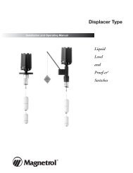
DESCRIPTION<br />
®<br />
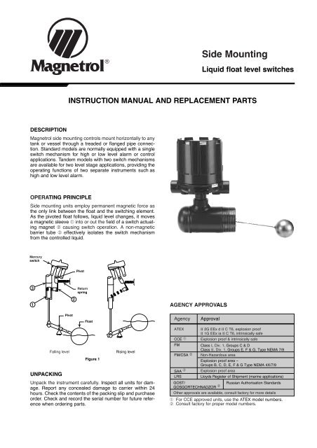
Side Mounting<br />
Liquid float level switches<br />
INSTRUCTION MANUAL AND REPLACEMENT PARTS<br />
<strong>Magnetrol</strong> side mounting controls mount horizontally to any<br />
tank or vessel through a treaded or flanged pipe connection.<br />
Standard models are normally equipped with a single<br />
switch mechanism for high or low level alarm or control<br />
applications. Tandem models with two switch mechanisms<br />
are available for two level stage applications, providing the<br />
operating functions of two separate instruments such as<br />
high and low level alarm.<br />
OPERATING PRINCIPLE<br />
Side mounting units employ permanent magnetic force as<br />
the only link between the float and the switching element.<br />
As the pivoted float follows, liquid level changes, it moves<br />
a magnetic sleeve ➀ into or out the field of a switch actuating<br />
magnet ➁ causing switch operation. A non-magnetic<br />
barrier tube ➂ effectively isolates the switch mechanism<br />
from the controlled liquid.<br />
Mercury<br />
switch<br />
3<br />
1<br />
4 5 6<br />
UNPACKING<br />
Pivot<br />
2<br />
Pivot<br />
Return<br />
spring<br />
Float<br />
4 5 6<br />
Falling level Rising level<br />
Figure 1<br />
Unpack the instrument carefully. Inspect all units for damage.<br />
Report any concealed damage to carrier within 24<br />
hours. Check the contents of the packing slip and purchase<br />
order. Check and record the serial number for future reference<br />
when ordering parts.<br />
AGENCY APPROVALS<br />
Agency Approval<br />
ATEX II 2G EEx d II C T6, explosion proof<br />
II 1G EEx ia II C T6, intrinsically safe<br />
CCE ➀ Explosion proof & intrinsically safe<br />
FM Class I, Div. 1, Groups C & D<br />
Class II, Div. 1, Groups E, F & G, Type NEMA 7/9<br />
FM/CSA ➁ Non-Hazardous area<br />
Explosion proof area –<br />
Groups B, C, D, E, F & G Type NEMA 4X/7/9<br />
SAA ➁ Explosion proof area<br />
LRS Lloyds Register of Shipment (marine applications)<br />
GOST/<br />
GOSGORTECHNADZOR<br />
Russian Authorisation Standards<br />
➁<br />
Other approvals are available, consult factory for more details<br />
➀ For CCE approved units, use the ATEX model numbers.<br />
➁ Consult factory for proper model numbers.
MODEL IDENTIFICATION<br />
A complete measuring system consists of:<br />
1. Code for side mounted models (each unit can be factory calibrated when specific level differentials are specified separately).<br />
2. Code for modified models or adders: put an "X" in front of the closest matching order code and specify the modifications/<br />
adders separately<br />
eg. XT62-AG3A-AAP X = with material certification EN 10204 / DIN 50049-3.1.B<br />
3. OPTION: External cage: consult factory for model description.<br />
1. Code for T62/T67 side mounted float level switch<br />
BASIC MODEL NUMBER1<br />
– Single switch model<br />
2<br />
T 6 2 down to S.G. 0,50 up to 34,5 bar (500 psi)<br />
– Dual switch model<br />
T 6 7 down to S.G. 0,50 up to 34,5 bar (500 psi)<br />
MATERIALS OF CONSTRUCTION<br />
Code<br />
A<br />
B<br />
PROCESS CONNECTION<br />
– threaded<br />
F 2 3" NPT<br />
– ANSI flanges<br />
G 3 3" 150 lbs ANSI RF<br />
G 4 3" 300 lbs ANSI RF<br />
H 3 4" 150 lbs ANSI RF<br />
H 4 4" 300 lbs ANSI RF<br />
.– DIN flanges<br />
7 F DN 80, PN 16 DIN 2527 form C<br />
7 G DN 80, PN 25/40 DIN 2527 form C<br />
8 F DN 100, PN 16 DIN 2527 form C<br />
8 G DN 100, PN 25/40 DIN 2527 form C<br />
➀ All floats can be screwed to float stem from inside of vessel in case the float cannot pass through the nozzle.<br />
SWITCH MECHANISM & ENCLOSURE - for T62 units (see page 3)<br />
- for T67 units (see page 4)<br />
- for pneumatic switch mechanisms (see table below)<br />
T 6 complete code for T62/T67 side mounted float level switch<br />
Select pneumatic switch mechanism & enclosure - for T62/T64 models<br />
Pneumatic switch type<br />
Series J<br />
(open air)<br />
Series K<br />
(closed circuit)<br />
Cage & process<br />
connection material<br />
Carbon steel<br />
D 316/316L (1.4401/1.4404)<br />
Max supply pressure<br />
bar (psi)<br />
Max liquid temperature<br />
°C (°F)<br />
Float and trim Magnetic sleeve<br />
316 SST (1.4401)<br />
Bleed orifice Ø<br />
mm (inches)<br />
400 series SST<br />
316 SST (1.4401)<br />
FLOAT AND STEM LENGTH<br />
Stem length versus min S.G.<br />
Float size<br />
mm (inches) ➀<br />
203 mm 305 mm 457 mm 660 mm<br />
(8") (12") (18") (26")<br />
Max pressure bar (psi)<br />
@ 40 °C @ 400 °C<br />
(100 °F) (750 °F)<br />
A 0,80 B 0,80 C 0,90 D 0,90 ø 64 (2.50) 24,1 (350) 13,8 (200)<br />
E 0,52 F 0,55 G 0,60 H 0,66 ø 64 x 102 (2.50 x 4.00) 6,9 (100) 4,1 (60)<br />
J 0,55 K 0,55 L 0,60 M 0,60 ø 76 (3.00) 17,2 (250) 10,3 (150)<br />
N 0,50 P 0,50 Q 0,55 R 0,55 ø 89 (3.50) 27,6 (400) 15,5 (225)<br />
S 0,65 T 0,65 V 0,70 W 0,70 ø 76 x 127 (3.00 x 5.00) 34,5 (500) 20,7 (300)<br />
NEMA 3R (IP 53)<br />
material code A material codes B & D<br />
6,9 (100) 200 (400) 1,60 (0.063) JDE JDE<br />
4,1 (60) 200 (400) 2,39 (0.094) JEE JEE<br />
4,1 (60) 370 (700) 1,40 (0.055) JFE JFE<br />
6,9 (100) 200 (400) – – KOE<br />
2,8 (40) 200 (400) – KOG –
1. Code for T64 side mounted float level switch<br />
BASIC MODEL NUMBER1<br />
– Single switch model<br />
T 6 4 down to S.G. 0,40 up to 82,7 bar (1200 psi)<br />
MATERIALS OF CONSTRUCTION<br />
Code<br />
Cage & process<br />
connection material<br />
PROCESS CONNECTION<br />
– ANSI flanges<br />
H 3 4" 150 lbs ANSI RF<br />
H 4 4" 300 lbs ANSI RF<br />
H 5 4" 600 lbs ANSI RF<br />
FLOAT AND STEM LENGTH<br />
N Fixed stem length: 203 mm (8")<br />
Min. S.G: 0,40<br />
Float size: ø 89 mm (3.50")<br />
Float rating: 82,7 bar (1200 psi) @ 40 °C (100 °F)<br />
400 °C (750 °F) @ 51,7 bar (750 psi)<br />
Float and trim Magnetic sleeve<br />
A Carbon steel 304 SST (1.4301) / 316 SST (1.4401) 400 series SST<br />
.– DIN flanges<br />
8 F DN 100, PN 16 DIN 2527 form C<br />
8 G DN 100, PN 25/40 DIN 2527 form C<br />
8 H DN 100, PN 64 DIN 2527 form E<br />
8 J DN 100, PN 100 DIN 2527 form E<br />
SWITCH MECHANISM & ENCLOSURE - for electric switch mechanisms (see table below)<br />
- for pneumatic switch mechanisms (see page 2)<br />
T 6 4 A N<br />
complete code for T64 side mounted float level switch<br />
Select electric switch mechanism & enclosure for T62 and T64 models (see page 3 for switch ratings)<br />
A<br />
3<br />
B<br />
C<br />
D<br />
F<br />
HS<br />
U<br />
qty and<br />
switch<br />
type<br />
Weather proof<br />
(IP 66)<br />
All models with material code A All models with material codes B and D<br />
ATEX (IP 66) FM (IP 66) Weather proof<br />
ATEX (IP 66) FM (IP 66)<br />
II 2G EEx d IIC T6 II 1G EEx ia II C T6 II 2G EEx d IIC T6 NEMA 7/9 (IP 66) II 2G EEx d IIC T6 II 1G EEx ia II C T6 II 2G EEx d IIC T6 NEMA 7/9<br />
cast Aluminium cast Aluminium cast Aluminium cast Iron cast Alu. cast Aluminium cast Aluminium cast Aluminium cast Iron cast Alu.<br />
M20 x 1,5 1" NPT M20 x 1,5 1" NPT M20 x 1,5 1" NPT M20 x 1,5 3/4" NPT 1" NPT M20 x 1,5 1" NPT M20 x 1,5 1" NPT M20 x 1,5 1" NPT M20 x 1,5 3/4" NPT 1" NPT<br />
1 x SPDT A2P AAP AHC AAC - - AK7 AU7 AKP A2Q AAQ AH9 AA9 - - AK5 AU5 AKQ<br />
1 x DPDT A8P ADP AJC ABC - - AD7 AW7 ANP A8Q ADQ AJ9 AB9 - - AD5 AW5 ANQ<br />
1 x SPDT 32P 3AP 3HC 3AC - - 3K7 3U7 3KP 32Q 3AQ 3H9 3A9 - - 3K5 3U5 3KQ<br />
1 x DPDT 38P 3DP 3JC 3BC - - 3D7 3W7 3NP 38Q 3DQ 3J9 3B9 - - 3D5 3W5 3NQ<br />
1 x SPDT B2P BAP BHC BAC - - BK7 BU7 BKP B2Q BAQ BH9 BA9 - - BK5 BU5 BKQ<br />
1 x DPDT B8P BDP BJC BBC - - BD7 BW7 BNP B8Q BDQ BJ9 BB9 - - BD5 BW5 BNQ<br />
1 x SPDT C2P CAP CHC CAC C2L CAL CK7 CU7 CKP C2Q CAQ CH9 CA9 C2S CAS CK5 CU5 CKQ<br />
1 x DPDT C8P CDP CJC CBC C8L CDL CD7 CW7 CNP C8Q CDQ CJ9 CB9 C8S CDS CD5 CW5 CNQ<br />
1 x SPDT - - - - - - - - - D2Q DAQ DH9 DA9 - - DK5 DU5 DKQ<br />
1 x DPDT - - - - - - - - - D8Q DDQ DJ9 DB9 - - DD5 DW5 DNQ<br />
1 x SPDT F2P FAP FHC FAC - - FK7 FU7 FKP F2Q FAQ FH9 FA9 - - FK5 FU5 FKQ<br />
1 x DPDT F8P FDP FJC FBC - - FD7 FW7 FNP F8Q FDQ FJ9 FB9 - - FD5 FW5 FNQ<br />
1 x SPDT - - - - - - - - - H7A HM2 HFC HA9 - - HB3 HB4 HM3<br />
1 x DPDT - - - - - - - - - H7C HM6 HGC HB9 - - HB7 HB8 HM7<br />
1 x SPDT U2P UAP UHC UAC U2L UAL UK7 UU7 UKP U2Q UAQ UH9 UA9 U2S UAS UK5 UU5 UKQ<br />
1 x DPDT U8P UDP UJC UBC U8L UDL UD7 UW7 UNP U8Q UDQ UJ9 UB9 U8S UDS UD5 UW5 UNQ<br />
V - - - - - VFS VHS - - - - - - - V5S VBS - - -<br />
W<br />
X<br />
1 x SPDT W2P WAP WHC WAC W2L WAL WK7 WU7 WKP W2Q WAQ WH9 WA9 W2S WAS WK5 WU5 WKQ<br />
1 x DPDT - - - - - - - - - W8Q WDQ WJ9 WB9 W8S WDS WD5 WW5 WNQ<br />
1 x SPDT X2P XAP XHC XAC X2L XAL XK7 XU7 XKP X2Q XAQ XH9 XA9 X2S XAS XK5 XU5 XKQ<br />
1 x DPDT - - - - - - - - - X8Q XDQ XJ9 XB9 X8S XDS XD5 XW5 XNQ<br />
3
4<br />
Select electric switch mechanism & enclosure for T67 models (see page 3 for switch ratings)<br />
A<br />
3<br />
B<br />
C<br />
D<br />
F<br />
U<br />
W<br />
X<br />
qty and<br />
switch<br />
type<br />
Weather proof<br />
(IP 66)<br />
All models with material code A All models with material codes B and D<br />
ATEX (IP 66) FM (IP 66) Weather proof<br />
ATEX (IP 66) FM (IP 66)<br />
II 2G EEx d II C T6 II 1G EEx ia II C T6 II 2G EEx d II C T6 NEMA 7/9 (IP 66) II 2G EEx d II C T6 II 1G EEx ia II C T6 II 2G EEx d II C T6 NEMA 7/9<br />
cast Aluminium cast Aluminium cast Aluminium cast Iron cast Alu. cast Aluminium cast Aluminium cast Aluminium cast Iron cast Alu.<br />
M20 x 1,5 1" NPT M20 x 1,5 1" NPT M20 x 1,5 1" NPT M20 x 1,5 3/4" NPT 1" NPT M20 x 1,5 1" NPT M20 x 1,5 1" NPT M20 x 1,5 1" NPT M20 x 1,5 3/4" NPT 1" NPT<br />
2 x SPDT A4A ABA ALC ADC - - AL7 AV7 ALA A4B ABB AL9 AD9 - - AL5 AV5 ALB<br />
2 x DPDT A1A AEA APC AGC - - AO7 AY7 AOA A1B AEB AP9 AG9 - - AO5 AY5 AOB<br />
2 x SPDT 34E 3BE 39E 3DE - - 3L7 3V7 3LE 34B 3BB 3L9 3D9 - - 3L5 3V5 3LB<br />
2 x DPDT 31A 3EA 3PC 3GC - - 3O7 3Y7 3OA 31B 3EB 3P9 3G9 - - 3O5 3Y5 3OB<br />
2 x SPDT B4A BBA BLC BDC - - BL7 BV7 BLA B4B BBB BL9 BD9 - - BL5 BV5 BLB<br />
2 x DPDT B1A BEA BPC BGC - - BO7 BY7 BOA B1B BEB BP9 BG9 - - BO5 BY5 BOB<br />
2 x SPDT C4A CBA CLC CDC C4X CBX CL7 CV7 CLA C4B CBB CL9 CD9 C4T CBT CL5 CV5 CLB<br />
2 x DPDT C1A CEA CPC CGC C1X CEX CO7 CY7 COA C1B CEB CP9 CG9 C1T CET CO5 CY5 COB<br />
2 x SPDT D4B DBB DL9 DD9 - - DL5 DV5 DLB D4B DBB DL9 DD9 - - DL5 DV5 DLB<br />
2 x DPDT D1B DEB DP9 DG9 - - DO5 DY5 DOB D1B DEB DP9 DG9 - - DO5 DY5 DOB<br />
2 x SPDT FFA FBA FLC FDC - - FL7 FV7 FLA FFB FBB FL9 FD9 - - FL5 FV5 FLB<br />
2 x DPDT FHA FEA FPC FGC - - FO7 FY7 FOA FHB FEB FP9 FG9 - - FO5 FY5 FOB<br />
2 x SPDT U4A UBA ULC UDC U4X UBX UL7 UV7 ULA U4B UBB UL9 UD9 U4T UBT UL5 UV5 ULB<br />
2 x DPDT U1A UEA UPC UGC U1X UEX UO7 UY7 UOA U1B UEB UP9 UG9 U1T UET UO5 UY5 UOB<br />
2 x SPDT W4A WBA WLC WDC W4X WBX WL7 WV7 WLA W4B WBB WL9 WD9 W4T WBT WL5 WV5 WLB<br />
2 x DPDT W1B WEB WP9 WG9 W1T WET WO5 WY5 WOB W1B WEB WP9 WG9 W1T WET WO5 WY5 WOB<br />
2 x SPDT X4A XBA XLC XDC X4X XBX XL7 XV7 XLA X4B XBB XL9 XD9 X4T XBT XL5 XV5 XLB<br />
2 x DPDT X1B XEB XP9 XG9 X1T XET XO5 XY5 XOB X1B XEB XP9 XG9 X1T XET XO5 XY5 XOB
MOUNTING<br />
Before assembling control to tank or vessel, check threaded<br />
or flanged mounting nozzle for the following:<br />
– Nozzle length and inside diameter must be sized correctly<br />
to allow for switch actuation at design levels within the<br />
maximum differential available (see table on page 4).<br />
– Nozzle should be checked for horizontal alignment.<br />
Finished mounting must allow control switch housing to<br />
be within 3° degrees of vertical for proper operation. A<br />
three degree slant is noticeable by eye, but installation<br />
should be checked with a spirit level.<br />
WIRING<br />
Most mechanical control switch housings are designed to<br />
allow 360° positioning of the cable entries by loosening the<br />
set screw(s). See figure 2. On high temperature applications<br />
(above 120° C [250° F]), high temperature wire should<br />
be used between control and first junction box located in a<br />
cooler area.<br />
1. To gain access to switch mechanism(s) remove switch<br />
housing cover.<br />
2. Pull in supply wires (conductors), wrap them around<br />
enclosing tube under the baffle plate and connect to<br />
proper terminals. Be certain that excess wire does not<br />
interfere with "tilt" of switch and that adequate clearance<br />
exists for replacement of switch housing cover.<br />
NOTE: See bulletin on switch mechanism furnished with<br />
your control (as listed below) for proper connections.<br />
3. Connect power supply to control and test switch action<br />
by varying liquid level in tank or vessel.<br />
NOTE: If switch mechanism fails to function properly, check<br />
vertical alignment of control housing and consult installation<br />
instructions in switch mechanism bulletin.<br />
4. Replace switch housing cover and place control into service.<br />
NOTE: If control has been furnished with an explosion proof<br />
(cast) or moisture proof (gasketed) switch housing, check<br />
the following:<br />
– After wiring connections have been completed, housings<br />
must be sealed via the correct cable gland to prevent<br />
entrance of air.<br />
– Check cover to base fit, to be certain gasketed joint is<br />
tight. A positive seal is necessary to prevent infiltration of<br />
moisture laden air or corrosive gases into switch housing.<br />
CAUTION:<br />
In hazardous area, do not power the unit until<br />
the cable gland is sealed and the enclosure<br />
cover is screwed down securely.<br />
Switch mechanism Bulletin Reference series<br />
Mercury switches 42-783 A<br />
Dry contact switches 42-683 B, C, D, U, W, X<br />
Anti-vibration mercury switches E<br />
Anti-vibration dry contact switches 42-684 G, H, I<br />
Bleed type pneumatic valve 42-685 J<br />
Non-bleed type pneumatic valve 42-686 K<br />
INSTALLATION<br />
OBSERVE ALL APPLICABLE ELECTRICAL CODES AND<br />
PROPER WIRING PROCEDURES<br />
NEMA 4x<br />
NEMA 7/9<br />
ATEX<br />
Set screw<br />
Set screw<br />
Locking screw<br />
Set screw<br />
Position<br />
screw<br />
Figure 2<br />
CAUTION:<br />
- DO NOT attempt to reposition NEMA 4 /<br />
NEMA 7/9 housings without loosening the<br />
set screws; ATEX housings MAY NOT BE<br />
REPOSITIONNED. ALWAYS retighten set<br />
screw(s) after repositionning.<br />
- DO NOT attempt to unscrew cover of ATEX<br />
housings before loosening locking screw in<br />
base of housing. ALWAYS retighten locking<br />
screw after replacing cover.<br />
5
The level differential setting of the side mounting controls<br />
can be field adjusted within limits specified in the table at<br />
right by repositioning the jam nuts on the magnetic sleeve<br />
stem.<br />
NOTE: The control need not be removed from tank or vessel<br />
to make differential adjustment.<br />
6<br />
CAUTION: Before attempting any work on the control,<br />
be certain to pull disconnect switch or otherwise<br />
assure that electrical circuit(s) through control is<br />
deactivated. Close operating medium supply valve on<br />
controls equipped with pneumatic switch mechanisms.<br />
1. Disconnect wiring from supply side of switch mechanism<br />
and electrical conduit or operating medium line connections<br />
to switch housing.<br />
2. Perform system shut-down as required to relieve pressure<br />
from tank or vessel and drain off liquid “head”<br />
above control mounting position. Allow unit to cool.<br />
3. Remove switch housing assembly by loosening hex nut<br />
located immediately below housing base.<br />
With switch housing removed, jam nuts and magnetic<br />
sleeve are now accessible, as in Figure 3. Raising the<br />
lower jam nuts or lowering the upper jam nuts will reduce<br />
the differential. Jam nut adjustments in opposite directions<br />
will, of course, increase the differential. As the first step in<br />
any adjustement procedure, the position of the lower jam<br />
nuts (dimension A) should be established.<br />
4. Loosen and remove upper jam nuts, guide washer and<br />
magnetic sleeve. Dimension “A”, as measured from top<br />
of stem to top of lower jam nuts, may now be increased<br />
or decreased as desired.<br />
Tandem model units have two switch mechanisms actuated<br />
by two independent magnetic sleeves. For adjustment<br />
purposes, each sleeve and jam nut set is considered as an<br />
individual unit in conjunction with the switch mechanism it<br />
operates.<br />
NOTE: Be certain to tighten jam nuts securely after adjustment.<br />
5. Replace magnetic sleeve on stem and position upper<br />
jam nuts to desired “B” dimension by measuring from<br />
top of sleeve to bottom of upper jam nuts. Lock upper<br />
jam nuts to guide washer.<br />
6. Reassemble control in reverse of steps 1 through 3, previously<br />
described.<br />
7. Test switch actuation by varying liquid level in tank or<br />
vessel.<br />
CAUTION: After increasing differential adjustment,<br />
be certain to check carefully for proper operation of<br />
switch mechanism. Magnet must “snap” cleanly with<br />
additional float movement available after magnet<br />
snaps.<br />
LEVEL DIFFERENTIAL ADJUSTMENT<br />
lower<br />
jam nuts<br />
magnetic<br />
sleeve<br />
magnetic<br />
sleeve stem<br />
Inches<br />
guide washer<br />
A B<br />
Millimeters<br />
pivot<br />
float stem length<br />
minus approx. 3 /4"<br />
upper jam nuts<br />
pivot<br />
CL<br />
Figure 3<br />
high level<br />
of control – differential –<br />
low level<br />
Differentials Obtainable ➁ ➃ Approx. Jam<br />
Model ➀<br />
Float Stem Length<br />
203 305 457 660<br />
Nut Setting ➂<br />
A B<br />
T62 Min. 32 51 73 102 21 0.8<br />
(Threaded) Max. 148 206 294 409 33 27<br />
T62 Min. 32 41 67 95 16 0.8<br />
(Flanged) Max. 89 130 191 273 28 18<br />
Differentials Obtainable ➁ ➃ Approx. Jam<br />
Model ➀<br />
Float Stem Length<br />
8.00 12.00 18.00 26.00<br />
Nut Setting ➂<br />
A B<br />
T62 Min. 1.25 2.00 2.88 4.00 0.81 0.03<br />
(Threaded) Max. 5.81 8.12 11.56 16.12 1.31 1.06<br />
T62 Min. 1.25 1.62 2.62 3.75 0.62 0.03<br />
(Flanged) Max. 3.50 5.12 7.50 10.75 1.12 0.69<br />
Notes:<br />
➀ All models are factory set at minimum differential unless otherwise<br />
specified.<br />
➁ To maintain maximum differential, nozzle length "L" (Fig. 2) must<br />
not exceed: 64 mm (2.50") model T62 threaded; or 89 mm (3.50")<br />
model T62 flanged.<br />
➂ Dimensions given are approximate and will vary slightly with each<br />
unit.<br />
➃ Consult factory for differentials of models not shown.<br />
float
LEVEL DIFFERENTIAL ADJUSTMENT (cont.)<br />
LEVEL DIFFERENTIAL VS. MOUNTING NOZZLE LENGTH<br />
The tables below may be used to determine the maximum level travel (differential) available between “Switch on” and “Switch<br />
off” actuations with mounting nozzles of different lengths. The differentials given occur with the minimum tank opening<br />
diameter listed for each model and are applicable to standard controls.<br />
Level differential in mm (inches)<br />
All units are factory set at minimum differential unless otherwise specified.<br />
Consult factory for differentials not shown.<br />
CL<br />
Models dim. "D" Differential dim. "L"<br />
T62<br />
threaded<br />
T62<br />
flanged<br />
T64 flanged<br />
T67<br />
threaded<br />
T67<br />
flanged<br />
of control<br />
77,9 mm (3.07")<br />
3" – Sch 40<br />
73,7 mm (2.90")<br />
3" – Sch 80<br />
102,3 mm (4.03")<br />
4" – Sch 40<br />
77,9 mm (3.07")<br />
3" – Sch 40<br />
73,7 mm (2.90")<br />
3" – Sch 80<br />
L<br />
ø D min. nozzle opening<br />
switch actuates<br />
rising level level diff.<br />
switch 1 level<br />
switch actuates<br />
level diff. differential<br />
switch 2<br />
falling level<br />
float<br />
T67 T62<br />
CL<br />
of control<br />
Float stem length versus level differential<br />
203 mm (8") 305 mm (12") 457 mm (18") 660 mm (26")<br />
min Not applicable 32 (1.26) 51 (2.01) 73 (2.87) 102 (4.02)<br />
50 mm (2") 148 (5.83) 206 (8.11) 294 (11.58) 409 (16.10)<br />
100 mm (4") 111 (4.37) 155 (6.10) 221 (8.70) 310 (12.20)<br />
max<br />
150 mm (6")<br />
200 mm (8")<br />
38 (1.50)<br />
-<br />
119 (4.69)<br />
97 (3.82)<br />
170 (6.69)<br />
138 (5.43)<br />
236 (9.29)<br />
192 (7.56)<br />
250 mm (10") - 81 (3.19) 116 (4.57) 162 (6.38)<br />
305 mm (12") - - 100 (3.94) 138 (5.43)<br />
min Not applicable 32 (1.26) 41 (1.61) 67 (2.64) 95 (3.74)<br />
50 mm (2") 89 (3.50) 130 (5.12) 191 (7.52) 273 (10.75)<br />
100 mm (4") 83 (3.27) 121 (4.76) 178 (7.01) 254 (10.00)<br />
max<br />
150 mm (6")<br />
200 mm (8")<br />
-<br />
-<br />
95 (3.74)<br />
76 (2.99)<br />
137 (5.39)<br />
114 (4.49)<br />
197 (7.76)<br />
159 (6.26)<br />
250 mm (10") - 64 (2.52) 95 (3.74) 137 (5.39)<br />
305 mm (12") - - 83 (3.27) 117 (4.61)<br />
fixed max 178 mm (7") 32 (1.26) Not applicable Not applicable Not applicable<br />
min max 57 mm 25 (1.00) 38 (1.50) 54 (2.12) 76 (3.00)<br />
max (2.25") 64 (2.50) 95 (3.75) 140 (5.50) 197 (7.75)<br />
min max 89 mm 25 (1.00) 38 (1.50) 54 (2.12) 76 (3.00)<br />
max (3.50") 48 (1.88) 68 (2.69) 99 (3.88) 140 (5.50)<br />
L<br />
ø D min. nozzle opening<br />
switch actuates<br />
rising level<br />
level diff.<br />
switch 1<br />
level<br />
differential<br />
switch actuates<br />
level diff.<br />
switch 2<br />
falling level<br />
float<br />
T67 T62/T64<br />
7
8<br />
PREVENTIVE MAINTENANCE<br />
Periodic inspections are a necessary means to keep your <strong>Magnetrol</strong> level control in good working order. This control<br />
is, in reality, a safety device to protect the valuable equipment it serves. Therefore, a systematic program of "preventive<br />
maintenance" should be implemented when control is placed into service. If the following sections on "what to<br />
do" and "what to avoid" are observed, your control will provide reliable protection of your capital equipment for many<br />
years.<br />
WHAT TO DO<br />
1. Keep control clean<br />
NEVER leave switch housing cover off the control. This<br />
cover is designed to keep dust and dirt from interfering<br />
with switch mechanism operation. In addition, it protects<br />
against damaging moisture and acts as a safety feature<br />
by keeping bare wires and terminals from being<br />
exposed. Should the housing cover become damaged<br />
or misplaced, order a replacement immediately.<br />
2. Inspect switch mechanisms, terminals and connections<br />
monthly.<br />
– Mercury switches may be visually inspected for short<br />
circuit damage. Check for small cracks in the glass<br />
tube containing the mercury. Such cracks can allow<br />
entrance of air into the tube causing the mercury to<br />
"oxidize". This is noticeable as the mercury will<br />
appear dirty and have a tendency to "string out" like<br />
water, instead of breaking into round pools. If these<br />
conditions exist, replace the mercury switch immediately.<br />
– Dry contact switches should be inspected for excessive<br />
wear on actuating lever or misalignment of<br />
adjusting screw at point of contact between screw<br />
and lever. Such wear can cause false switch actuating<br />
levels. Adjust switch mechanism to compensate<br />
(if possible) or replace switch.<br />
Do NOT operate your control with defective or maladjusted<br />
switch mechanisms (refer to bulletin on switch<br />
mechanism furnished for service instructions).<br />
– <strong>Magnetrol</strong> controls may sometimes be exposed to<br />
excessive heat or moisture. Under such conditions,<br />
insulation on electrical wires may become brittle,<br />
eventually breaking or peeling away. The resulting<br />
"bare" wires can cause short circuits.<br />
Check wiring carefully and replace at first sign of brittle<br />
insulation.<br />
–Vibration may sometimes cause terminal screws to<br />
work loose. Check all terminal connections to be certain<br />
that screws are tight. Air (or gas) operating medium<br />
lines subjected to vibration may eventually crack<br />
or become loose at connections causing leakage.<br />
Check lines and connections carefully and repair or<br />
replace, if necessary.<br />
– On units with pneumatic switches, air (or gas) operating<br />
medium lines subjected to vibration, may eventually<br />
crack or become loose at connections carefully<br />
and repair or replace, if necessary.<br />
NOTE: As a matter of good practice, spare switches should<br />
be kept on hand at all times.<br />
3. Inspect entire unit periodically<br />
Isolate control from vessel. Raise and lower liquid level<br />
to check for switch contact and reset.<br />
WHAT TO AVOID<br />
1. NEVER leave switch housing cover off the control longer<br />
than necessary to make routine inspections.<br />
2. NEVER use lubricants on pivots of switch mechanisms.<br />
A sufficient amount of lubricant has been applied at the<br />
factory to insure a lifetime of service. Further oiling is<br />
unnecessary and will only tend to attract dust and dirt<br />
which can interfere with mechanism operation.<br />
3. NEVER place a jumper wire across terminals to "cutout"<br />
the control. If a "jumper" is necessary for test purposes,<br />
be certain it is removed before placing control<br />
into service.<br />
4. NEVER attempt to make adjustments or replace switches<br />
without reading instructions carefully. Certain adjustments<br />
provided for in <strong>Magnetrol</strong> controls should not be<br />
attempted in the field. When in doubt, consult the factory<br />
or your local <strong>Magnetrol</strong> representative.
Usually the first indication of improper operation is failure of<br />
the controlled equipment to function, i.e.: pump will not start<br />
(or stop), signal lamps fail to light, etc. When these<br />
symptoms occur, whether at time of installation or during<br />
routine service thereafter, check the following potential<br />
external causes first.<br />
— Fuses may be blown.<br />
— Reset button(s) may need resetting.<br />
— Power switch may be open.<br />
— Controlled equipment may be faulty.<br />
— Wiring leading to control may be defective.<br />
If a thorough inspection of these possible conditions fails to<br />
locate the trouble, proceed next to a check of the control’s<br />
switch mechanism.<br />
CHECK SWITCH MECHANISM<br />
1. Pull disconnect switch or otherwise disconnect power to<br />
the control.<br />
2. Remove switch housing cover.<br />
3. Disconnect power wiring from switch assembly.<br />
4. Swing magnet assembly in and out by hand to check<br />
carefully for any sign of binding. Assembly should<br />
require minimal force to move it through its full swing.<br />
5. If binding exists, magnet may be rubbing enclosing<br />
tube. If magnet is rubbing, loosen magnet clamp screw<br />
and shift magnet position. Retighten magnet clamp<br />
screw.<br />
6. If switch magnet assembly swings freely and mechanism<br />
still fails to actuate, check installation of control to be certain<br />
it is within the specified three (3°) degrees of vertical<br />
(Use spirit level on side of enclosing tube in two place, 90°<br />
apart).<br />
7. If mechanism is equipped with a mercury switch,<br />
examine glass mercury tube closely as previously<br />
described in “Preventive Maintenance” section. If<br />
switch is damaged, replace it immediately.<br />
8. If switch mechanism is operating satisfactorily, proceed<br />
to check sensing unit.<br />
CHECK SENSING UNIT<br />
1. Re-connect power supply and carefully actuate switch<br />
mechanism manually (using a non-conductive tool) to<br />
determine whether controlled equipment will operate.<br />
CAUTION:<br />
With electrical power “on”, care should be taken<br />
to avoid contact with switch leads and connections<br />
at terminal block.<br />
TROUBLE SHOOTING<br />
2. If controlled equipment responds to manual actuation<br />
test, trouble may be located in the level sensing portion<br />
of the control (float, stem and magnetic attraction<br />
sleeve[s]).<br />
NOTE: Check first to be certain liquid is entering storage<br />
tank or vessel. A valve may be closed or pipe line plugged.<br />
3. With liquid in tank or vessel, proceed to check level<br />
sensing action by removing switch housing assembly.<br />
4. Inspect magnetic attraction sleeve(s) and inside of<br />
enclosing tube for excessive corrosion or solids buildup<br />
which could restrict movement, preventing sleeve(s)<br />
from reaching field of magnet(s).<br />
5. If differential has been changed in the field, check tightness<br />
and position of the jam nuts.<br />
NOTE: Differential adjustment affects a change in the<br />
amount of level travel between “switch on” and “switch off”<br />
actuations. Do NOT attempt adjustment without first consulting<br />
factory for assistance in computing level differential<br />
change for your control.<br />
6. Check float to be certain it is buoyant in the liquid (tank<br />
or vessel must have adequate liquid level). If float is<br />
determined to be filled with liquid or collapsed, it must<br />
be replaced immediately. Do NOT attempt to repair a<br />
float.<br />
If all the components in the control are in operating condition,<br />
the trouble must be (and should be) located external<br />
to the control. Repeat inspection of external conditions previously<br />
described.<br />
NOTE: When in doubt about the condition or performance<br />
of a <strong>Magnetrol</strong> control, return it to the factory. See “Our<br />
Service Policy” on back page.<br />
9
Z<br />
W<br />
78*<br />
(3.07)<br />
10<br />
X<br />
Y<br />
114 (4.50)<br />
219 (8.62)<br />
model T62/T67 threaded<br />
DIMENSIONAL SPECIFICATIONS in mm (inches)<br />
V<br />
this dimension<br />
equals float,<br />
+ stem length,<br />
minus 66<br />
(2.60)<br />
* Dimensions for all housings, except for cast iron<br />
housing, add for these 76 mm (3")<br />
Housing type Models<br />
Weatherproof-<br />
FM (NEMA 7/9) -<br />
ATEX (Cast Alu)<br />
T62/T64 with HS-switch<br />
and T67<br />
Allow 200 mm (7.87") overhead clearance / All housings are 360 ° rotatable<br />
Z<br />
W<br />
90*<br />
(3.54)<br />
X<br />
Y<br />
V<br />
137 (5.39) 267 (10.50)<br />
267 (10.50)<br />
model T64 flanged<br />
W<br />
Z<br />
78*<br />
(3.07)<br />
min level<br />
differential<br />
32 (1.25)<br />
V W ø X Y<br />
mm inches mm inches mm inches mm inches<br />
257 10.12<br />
T62/T64 excl. HS-switch 202 7.94<br />
42 1.66 151 5.93 109 4.29<br />
ATEX (Cast Iron) All 249 9.80 45 1.77 143 5.63 110 4.33<br />
Pneumatics<br />
Switch Module J<br />
Pneumatics<br />
Switch Module K<br />
(T52 & T57)<br />
T62/T64 165 6.50 39 1.54 118 4.65<br />
REPLACEMENT PARTS<br />
Spacer bracket for tandem<br />
switch mechanisms<br />
Serial no. tag (ref.)<br />
(T63 & T68)<br />
(T62 & T67)<br />
threaded<br />
X<br />
110 4.33<br />
130 5.12<br />
Y<br />
124 (4.88)<br />
229 (9.00)<br />
V<br />
model T62/T67 flanged<br />
Z<br />
this dimension<br />
equals float,<br />
+ stem length,<br />
minus 76<br />
(3.00)<br />
M20 x 1,5 (*) or 1" NPT<br />
(2 entries - 1 plugged)<br />
(*) not for FM (NEMA 7/9)<br />
M20 x 1,5 or 3/4" NPT<br />
(single entry - 2 entries at request)<br />
1/4" NPT<br />
Serial no. tag (ref.)<br />
(T62 & T67)<br />
flanged
Item Description<br />
1 Switch housing cover Housing<br />
2 Switch housing base<br />
kits<br />
REPLACEMENT PARTS<br />
N/R = not required – N/A = not available<br />
① All replacement assemblies listed are for standard base models which use Ref. series A, B, C, D, E and J switch mechanisms<br />
only. Consult local representative for ordering assistance on all special model replacement parts not included in the<br />
above listing.<br />
② Sheathed attraction sleeves are used on models specified for corrosive service. Standard sleeve is type 400 series stainless<br />
steel.<br />
③ Flange gasket used on T62, T64 and T67 units is standard ANSI type, readily available at local supply houses.<br />
④ Sheathed sleeve stem kits are used on models with Material of Construction Codes 2 through 9.<br />
⑤ Above 300 Lb. rating, use 12-1204-001.<br />
⑥ Dimensions in millimeters (inches).<br />
IMPORTANT:<br />
When ordering, please specify:<br />
A. Model and serial number of control.<br />
B. Name and number of replacement assembly.<br />
T62<br />
threaded<br />
Replacement assemblies ➀<br />
T62<br />
flanged<br />
Model<br />
T64<br />
T67<br />
threaded<br />
T67<br />
flanged<br />
See bulletin BE 42-680/BE 42-780 ref. A, B, C, D & E switch housings replacement assemblies.<br />
Consult factory on series G, H, I, J & K.<br />
3 Switch mechanism(s) — See bulletin on switch mechanism(s) furnished, as listed below.<br />
4 Spacer bracket —<br />
05-7542-121<br />
N/R<br />
5 Round head screws (2) — 10-1409-006<br />
6 Attraction sleeve(s)<br />
7 Jam nuts<br />
8 Guide washer<br />
9 Sleeve stem<br />
10 Connecting pin<br />
11 Fulcrum<br />
12 Fulcrum pin<br />
13 Pivot bracket<br />
14 Round head mach. screws<br />
15 Float stem<br />
16 Stem lock nuts<br />
Stem<br />
kits<br />
➁<br />
Kits shown<br />
contain<br />
203 mm (8.08")<br />
stem lengths.<br />
Consult factory<br />
for<br />
longer<br />
stem lengths.<br />
89-5510-001<br />
Standard sleeve<br />
89-5514-001<br />
Sheathed sleeve<br />
④<br />
—<br />
89-5512-001<br />
Standard<br />
sleeve<br />
89-5511-001<br />
Standard<br />
sleeve<br />
ø 64 (2,5") 89-5546-001 89-5546-001<br />
ø 64 x 102<br />
(2,5" x4")<br />
89-5553-001 89-5553-001<br />
ø 76 (3") 89-5551-001 89-5551-001<br />
17 Float ⑥<br />
ø 89 (3,5") 89-5552-001 07-1101-012 89-5552-001<br />
ø 76 x 127<br />
(3" x 5")<br />
89-5554-001<br />
89-5554-001<br />
ø 76 x 152<br />
(3" x 6")<br />
89-5555-001<br />
—<br />
89-5555-001<br />
18 Body — 33-6120-001 33-6124-001 33-6120-001 33-6124-001<br />
19 E-tube gasket — 12-1301-002 ➄<br />
20 Enclosing tube<br />
Materiel<br />
code<br />
1,2<br />
Materiel<br />
code<br />
4<br />
NEMA 4<br />
NEMA 7/9<br />
Pneumatic<br />
housing<br />
32-6302-031 32-6302-033<br />
ATEX 32-6344-002<br />
NEMA 4<br />
NEMA 7/9<br />
Pneumatic<br />
housing<br />
32-6302-036 32-6302-037<br />
ATEX 32-6344-001<br />
21 Flange gasket — N/R N/A ③ N/R N/A ③<br />
11
IMPORTANT<br />
SERVICE POLICY<br />
Owners of <strong>Magnetrol</strong> products may request the return of a control; or, any part of a control for complete rebuilding or<br />
replacement. They will be rebuilt or replaced promptly. <strong>Magnetrol</strong> <strong>International</strong> will repair or replace the control, at no cost to<br />
the purchaser, (or owner) other than transportation cost if:<br />
a. Returned within the warranty period; and,<br />
b. The factory inspection finds the cause of the malfunction to be defective material or workmanship.<br />
If the trouble is the result of conditions beyond our control; or, is NOT covered by the warranty, there will be charges for labour<br />
and the parts required to rebuild or replace the equipment.<br />
In some cases, it may be expedient to ship replacement parts; or, in extreme cases a complete new control, to replace the original<br />
equipment before it is returned. If this is desired, notify the factory of both the model and serial numbers of the<br />
control to be replaced. In such cases, credit for the materials returned, will be determined on the basis of the applicability of our<br />
warranty.<br />
No claims for misapplication, labour, direct or consequential damage will be allowed.<br />
RETURNED MATERIAL PROCEDURE<br />
So that we may efficiently process any materials that are returned, it is essential that a “Return Material Authorisation” (RMA)<br />
form will be obtained from the factory. It is mandatory that this form will be attached to each material returned. This form is available<br />
through <strong>Magnetrol</strong>’s local representative or by contacting the factory. Please supply the following information:<br />
1. Purchaser Name<br />
2. Description of Material<br />
3. Serial Number<br />
4. Desired Action<br />
5. Reason for Return<br />
6. Process details<br />
All shipments returned to the factory must be by prepaid transportation. <strong>Magnetrol</strong> will not accept collect shipments.<br />
All replacements will be shipped FOB factory.<br />
UNDER RESERVE OF MODIFICATIONS<br />
®<br />
www.magnetrol.com<br />
BULLETIN N°: BE 44-602.12<br />
EFFECTIVE: JANUARY 2005<br />
SUPERSEDES: December 1996<br />
BENELUX Heikensstraat 6, 9240 Zele, België<br />
Tel. +32 (0)52.45.11.11 • Fax. +32 (0)52.45.09.93 • E-Mail: info@magnetrol.be<br />
DEUTSCHLAND Alte Ziegelei 2-4, D-51491 Overath<br />
Tel. 02204 / 9536-0 • Fax. 02204 / 9536-53 • E-Mail: vertrieb@magnetrol.de<br />
FRANCE 40 - 42, rue Gabriel Péri, 95130 Le Plessis Bouchard<br />
Tél. 01.34.44.26.10 • Fax. 01.34.44.26.06 • E-Mail: magnetrolfrance@magnetrol.fr<br />
ITALIA Via Arese 12, I-20159 Milano<br />
Tel. (02) 607.22.98 (R.A.) • Fax. (02) 668.66.52 • E-Mail: mit.gen@magnetrol.it<br />
UNITED Unit 1 Regent Business Centre, Jubilee Road Burgess Hill West Sussex RH 15 9TL<br />
KINGDOM Tel. (01444) 871313 • Fax (01444) 871317 • E-Mail: sales@magnetrol.co.uk<br />
INDIA E-22, Anand Niketan, New Delhi - 110 021<br />
Tel. 91 (11) 6186211 • Fax 91 (11) 6186418 • E-Mail: info@magnetrolindia.com