Instruction Manual - Magnetrol International
Instruction Manual - Magnetrol International
Instruction Manual - Magnetrol International

You also want an ePaper? Increase the reach of your titles
YUMPU automatically turns print PDFs into web optimized ePapers that Google loves.
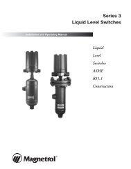
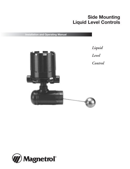
Installation and Operating <strong>Manual</strong><br />
Side Mounting<br />
Liquid Level Controls<br />
Liquid<br />
Level<br />
Control
Read this <strong>Manual</strong> Before Installing<br />
This manual provides information on Side Mounting<br />
Liquid Level Controls. It is important that all instructions<br />
are read carefully and followed in sequence. Detailed<br />
instructions are included in the Installation section of<br />
this manual.<br />
Conventions Used in this <strong>Manual</strong><br />
Certain conventions are used in this manual to convey<br />
specific types of information. General technical material,<br />
support data, and safety information are presented in<br />
narrative form. The following styles are used for notes,<br />
cautions, and warnings.<br />
NOTES<br />
Notes contain information that augments or clarifies<br />
an operating step. Notes do not normally contain<br />
actions. They follow the procedural steps to which<br />
they refer.<br />
Cautions<br />
Cautions alert the technician to special conditions that<br />
could injure personnel, damage equipment, or reduce<br />
a component’s mechanical integrity. Cautions are also<br />
used to alert the technician to unsafe practices or the<br />
need for special protective equipment or specific<br />
materials. In this manual, a caution box indicates a<br />
potentially hazardous situation which, if not avoided,<br />
may result in minor or moderate injury.<br />
WARNINGS<br />
Warnings identify potentially dangerous situations or<br />
serious hazards. In this manual, a warning indicates an<br />
imminently hazardous situation which, if not avoided,<br />
could result in serious injury or death.<br />
Safety Messages<br />
Follow all standard industry procedures for servicing electrical<br />
equipment when working with or around high<br />
voltage. Always shut off the power supply before touching<br />
any components.<br />
Low Voltage Directive<br />
For use in Installation Category II, Pollution Degree 2. If<br />
equipment is used in a manner not specified by the<br />
manufacturer, protection provided by the equipment<br />
may be impaired.<br />
Notice of Trademark, Copyright, and Limitations<br />
<strong>Magnetrol</strong> & <strong>Magnetrol</strong> logotype are registered<br />
trademarks of <strong>Magnetrol</strong> <strong>International</strong>.<br />
Copyright © 2010 <strong>Magnetrol</strong> <strong>International</strong>,<br />
Incorporated. All rights reserved.<br />
Performance specifications are effective with date of issue<br />
and are subject to change without notice. <strong>Magnetrol</strong><br />
reserves the right to make changes to the<br />
product described in this manual at any time without<br />
notice. <strong>Magnetrol</strong> makes no warranty with respect to the<br />
accuracy of the information in this manual.<br />
Warranty<br />
All <strong>Magnetrol</strong> mechanical level and flow controls are<br />
warranted free of defects in materials or workmanship for<br />
five full years from the date of original factory shipment.<br />
Repair parts are warranted free of defects in materials and<br />
workmanship for one year from the date of shipment.<br />
Materials, specifications, and contents are subject to<br />
change without prior written notice.<br />
If returned within the warranty period; and, upon factory<br />
inspection of the control, the cause of the claim is<br />
determined to be covered under the warranty; then,<br />
<strong>Magnetrol</strong> will repair or replace the control at no cost to<br />
the purchaser (or owner) other than transportation.<br />
<strong>Magnetrol</strong> shall not be liable for misapplication, labor<br />
claims, direct or consequential damage or expense arising<br />
from the installation or use of equipment.<br />
There are no other warranties expressed or implied,<br />
except special written warranties covering some<br />
<strong>Magnetrol</strong> products.<br />
Quality Assurance<br />
The quality assurance system in place at <strong>Magnetrol</strong><br />
guarantees the highest level of quality throughout<br />
the company. <strong>Magnetrol</strong> is committed to providing full<br />
customer satisfaction both in quality products and quality<br />
service.<br />
<strong>Magnetrol</strong>’s quality assurance system<br />
is registered to ISO 9001 affirming its<br />
commitment to known international<br />
quality standards providing the<br />
strongest assurance of product/service<br />
quality available.
Table of Contents<br />
1.0 Introduction<br />
1.1 Principle of Operation .............................................4<br />
1.2 Operating Cycle.......................................................4<br />
2.0 Installation .....................................................................4<br />
2.1 Unpacking ...............................................................4<br />
2.2 Mounting.................................................................5<br />
2.3 Wiring .....................................................................6<br />
2.4 Differential Adjustment ...........................................8<br />
2.4.1 Level Differential vs. Mounting Nozzle<br />
Length.........................................................10<br />
3.0 Reference Information<br />
3.1 Preventive Maintenance .........................................11<br />
3.1.1 What To Do................................................11<br />
3.1.2 What To Avoid............................................12<br />
3.2 Troubleshooting.....................................................13<br />
3.2.1 Check Switch Mechanism...........................13<br />
3.2.2 Check Sensing Unit ....................................14<br />
3.2.3 Check Complete Unit.................................14<br />
Side Mounting<br />
Liquid Level Controls<br />
3.3 Agency Approvals...................................................15<br />
3.4 Specifications .........................................................16<br />
3.4.1 Dimensional Specifications .........................16<br />
3.4.2 Actuation Levels..........................................18<br />
3.5 Replacement Parts..................................................19<br />
3.5.1 Replacement Assemblies Parts<br />
Identification...............................................19<br />
3.5.2 Models T52 and T63 ..................................20<br />
3.5.3 Models T62 Threaded, T62 Flanged,<br />
T67 Threaded and T67 Flanged .................21<br />
3.6 Model Numbers.....................................................22<br />
3.6.1 T52, T62, T63, T64 and T67 Models ........22
3<br />
1<br />
Pivot<br />
Figure 1<br />
Pivot<br />
Return<br />
Spring<br />
2<br />
Swing out<br />
position<br />
Figure 2<br />
Pivot<br />
Return<br />
spring<br />
Float<br />
1.0 Introduction<br />
Side mounting controls mount horizontally to any tank<br />
or vessel through a threaded or flanged pipe connection.<br />
Standard models are equipped with a single switch<br />
mechanism for high or low level alarm or control applications.<br />
Tandem models, with two switch mechanisms, are<br />
available for two level stage applications—providing the<br />
operating functions of two separate instruments, such as<br />
high and low level alarm.<br />
1.1 Principle of Operation<br />
Side mounting units employ permanent magnetic force as<br />
the only link between the float and the switching element.<br />
As the pivoted float follows liquid level changes, it moves<br />
a magnetic sleeve (1) into or out of the field of a switch<br />
actuating magnet (2) causing switch operation. A nonmagnetic<br />
barrier tube (3) effectively isolates the switch<br />
mechanism from the controlled liquid.<br />
1.2 Operating Cycle<br />
As the liquid level falls in the vessel, refer to Figure 1, the<br />
float moves the magnetic attraction sleeve up within the<br />
enclosing tube and into the field of the switch mechanism<br />
magnet. As a result, the magnet is drawn in tightly to the<br />
enclosing tube causing the switch to trip, making or breaking<br />
an electrical circuit. As the liquid level rises, the float<br />
moves the attraction sleeve out of the magnetic field,<br />
releasing the switch at a predetermined level. Refer to<br />
Figure 2. The tension spring ensures the return of the<br />
switch in a snap action.<br />
2.0 Installation<br />
Caution: If equipment is used in a manner not specified by the<br />
manufacturer, protection provided by the equipment may<br />
be impaired.<br />
2.1 Unpacking<br />
Unpack the instrument carefully, making sure all components<br />
have been removed from the packing material.<br />
Inspect all components for damage, and report any<br />
concealed damage to the carrier within 24 hours.<br />
4 44-602 Side Mounting Liquid Level Controls
Fulcrum Pin<br />
Fulcrum Bar<br />
Figure 3<br />
Float Stem Assembly<br />
Check the contents of the carton, making sure it agrees<br />
with the packing slip and the purchase order. Verify that<br />
the model number imprinted on the nameplate matches<br />
the number on the packing slip and the purchase order.<br />
Report any discrepancies to the factory. Check and record<br />
the serial number for future reference when ordering parts.<br />
2.2 Mounting<br />
Caution: This instrument is intended for use in Installation Category<br />
II, Pollution Degree 2.<br />
Before assembling control to tank or vessel, check threaded<br />
or flanged mounting nozzle for the following:<br />
• Nozzle length and inside diameter must be sized correctly<br />
to allow for switch actuation at design levels within the<br />
maximum differential available. Refer to the chart on<br />
page 10.<br />
• Nozzle should be checked for horizontal alignment.<br />
Finished mounting must allow control switch housing to<br />
be within 3° of vertical for proper operation. A three<br />
degree slant is noticeable by eye, but installation should<br />
be checked with a spirit level on top and/or sides of<br />
float body.<br />
Caution: Operation of all buoyancy type level devices should be<br />
done in such a way as to minimize the action of dynamic<br />
forces on the float or displacer sensing element. Good<br />
Lock Nut<br />
practice for reducing the likelihood of damage to the con-<br />
Float Stem trol is to equalize pressure across the device very slowly.<br />
• Before installation, assemble float and stem to sensing<br />
unit. See Figure 3.<br />
1. Remove screw from end of fulcrum bar and replace with<br />
float stem.<br />
2. Make sure end of float stem sets completely in groove of<br />
fulcrum pin as shown in Figure 3.<br />
3 Tighten lock nut with wrench. If float stem is properly<br />
located, fulcrum pin can not be pushed out.<br />
44-602 Side Mounting Liquid Level Controls 5
Screw<br />
Set<br />
Screw<br />
Screw<br />
Figure 4<br />
NEMA 4X, NEMA 4X/7/9<br />
NEMA 4X/7/9 Group B<br />
2.3 Wiring<br />
Caution: Level controls are shipped from the factory with the<br />
enclosing tube tightened and the middle set screw, on the<br />
housing base, locked to the enclosing tube. Failure to<br />
loosen the set screw prior to repositioning the conduit<br />
connection may cause the enclosing tube to loosen,<br />
resulting in the possible leakage of the process liquid<br />
or vapor.<br />
Side mounting controls are shipped with the conduit entry<br />
of the switch housing placed 180° opposite to the tank<br />
connections to simplify installation in most cases. If this<br />
configuration is appropriate to the installation, proceed to<br />
Step 4 to begin wiring the unit. If another configuration is<br />
desired, the switch housing can be easily rotated by first<br />
following Steps 1, 2, and 3.<br />
NOTE: A switch or circuit breaker shall be installed in close proximity<br />
to equipment and within easy reach of operator. It shall be<br />
marked as the disconnecting device for the equipment.<br />
1. Loosen set screw(s) at base of switch housing. Refer to<br />
Figure 4.<br />
2. Switch housing may be rotated 360° to allow correct<br />
positioning of conduit outlet.<br />
3. Tighten set screw(s) at base of switch housing.<br />
4. Unscrew and remove switch housing cover. The threads<br />
have been lubricated to facilitate removal.<br />
5. The switch terminals are located next to the conduit outlet<br />
to facilitate wiring. Bring supply wires through conduit<br />
outlet. Route extra wire around enclosing tube under the<br />
baffle plate, and connect them to the proper terminals.<br />
Refer to the wiring diagram in your switch bulletin for<br />
this information. Switch instruction manual numbers are<br />
as indicated in chart on page 7.<br />
6 44-602 Side Mounting Liquid Level Controls
Internal Circuit<br />
(Left) Switch<br />
Load<br />
Close on low level<br />
Common<br />
Close on high level<br />
Load<br />
Line<br />
4<br />
5<br />
6<br />
Figure 5<br />
Wiring diagram for<br />
side-mounted float switch<br />
(except HS)<br />
1<br />
2<br />
3<br />
NOTE: Housing must be grounded via protective ground screw in<br />
base of housing.<br />
Internal Circuit<br />
(Right) Switch<br />
Load<br />
Close on low level<br />
Common<br />
Close on high level<br />
Load<br />
Switch Series<br />
Bulletin<br />
Description<br />
Letter No.<br />
B, C, D Dry Contact Switch 42-683<br />
6. Dress wiring to ensure no interference or contact<br />
with the switch, or replacement of switch housing<br />
cover.<br />
OBSERVE ALL APPLICABLE ELECTRICAL<br />
CODES AND PROPER WIRING<br />
PROCEDURES.<br />
Prevent moisture seepage into the enclosure by<br />
installing approved seal-drain fittings in the<br />
conduit run leading into the unit.<br />
Line Caution: In hazardous areas, do not power the unit until<br />
the conduit is sealed and the enclosure is<br />
screwed down securely.<br />
7. Replace housing cover.<br />
8. If control has been furnished with an explosion<br />
proof or moisture proof (gasketed) switch housing,<br />
it must be sealed at the conduit outlet with<br />
a suitable compound or non-hardening sealant to<br />
prevent entrance of air.<br />
9. Test switch action by varying liquid level in float chamber.<br />
NOTE: If switch mechanism fails to function properly, check vertical<br />
alignment of control housing and consult installation bulletin<br />
on switch mechanism furnished.<br />
10. Check cover to base fit to be certain gasketed joint is tight.<br />
A positive seal is necessary to prevent infiltration of moisture<br />
laden air or corrosive gasses into switch housings.<br />
44-602 Side Mounting Liquid Level Controls 7<br />
G, H, I<br />
Vibration Resistant Dry Contact<br />
Switch, Dual Magnets<br />
42-684<br />
HS Hermetically Sealed Snap Switch 42-694<br />
J Bleed Type Pneumatic Switch 42-685<br />
K Non-Bleed Type Pneumatic Switch 42-686<br />
F, R, 8, 9 High Temperature Dry Contact Switch 42-799<br />
NOTE: For supply connections, use wire with a minimum rating of<br />
+167° F (+75° C) as required by the process conditions. Use<br />
a minimum of 14 AWG wire for power and ground field wires.
B<br />
Guide<br />
washer<br />
Lower<br />
jam nuts<br />
Magnetic<br />
sleeve<br />
Magnetic<br />
sleeve stem<br />
Pivot<br />
Float stem length<br />
minus approx. 3/4"<br />
Upper jam nuts<br />
Pivot<br />
Figure 6<br />
A<br />
CL<br />
of control<br />
2.4 Differential Adjustment<br />
High level<br />
Differential<br />
Low level<br />
Float<br />
The level differential of single switch models may be<br />
adjusted by repositioning the jam nuts on the magnetic<br />
sleeve stem as shown in Figure 6.<br />
Refer to the chart below for the minimum and maximum<br />
levels obtainable.<br />
Inches (millimeters)<br />
Differentials Obtainable ➁➃ Approx. Jam<br />
Model ➀<br />
Float Stem Length<br />
8.00 12.00 18.00 26.00<br />
(230) (305) (457) (660)<br />
Nut Setting ➂<br />
A B<br />
T52<br />
Min.<br />
Max.<br />
1.25<br />
(32)<br />
4.75<br />
(121)<br />
1.75<br />
(44)<br />
7.00<br />
(178)<br />
2.50<br />
(64)<br />
10.25<br />
(260)<br />
3.50<br />
(89)<br />
14.50<br />
(368)<br />
0.81<br />
(21)<br />
1.31<br />
(33)<br />
0.03<br />
(0.8)<br />
1.06<br />
(27)<br />
T63<br />
Min.<br />
Max.<br />
1.00<br />
(25)<br />
2.62<br />
(67)<br />
1.75<br />
(44)<br />
5.00<br />
(127)<br />
2.50<br />
(64)<br />
7.38<br />
(187)<br />
3.50<br />
(89)<br />
10.50<br />
(267)<br />
0.81<br />
(21)<br />
1.31<br />
(33)<br />
0.03<br />
(0.8)<br />
1.06<br />
(27)<br />
T62<br />
Min.<br />
1.25<br />
(32)<br />
2.00<br />
(51)<br />
2.88<br />
(73)<br />
4.00<br />
(102)<br />
0.81<br />
(21)<br />
0.03<br />
(0.8)<br />
(Threaded)<br />
Max.<br />
5.81<br />
(148)<br />
8.12<br />
(206)<br />
11.56<br />
(294)<br />
16.12<br />
(409)<br />
1.31<br />
(33)<br />
1.06<br />
(27)<br />
T62<br />
Min.<br />
1.25<br />
(32)<br />
1.62<br />
(41)<br />
2.62<br />
(67)<br />
3.75<br />
(95)<br />
0.62<br />
(16)<br />
0.03<br />
(0.8)<br />
(Flanged)<br />
Max.<br />
3.50<br />
(89)<br />
5.12<br />
(130)<br />
7.50<br />
(191)<br />
10.75<br />
(273)<br />
1.12<br />
(28)<br />
0.69<br />
(18)<br />
NOTES:<br />
➀ All models are factory set at minimum differential unless otherwise<br />
specified.<br />
➁ To maintain maximum differential, nozzle length "L" (Fig. 3) must<br />
not exceed: 2.38" (60 mm) model T52; 1.19" (30 mm) model T63;<br />
2.50" (64 mm) model T62 threaded; or 3.50" (89 mm) model T62<br />
flanged.<br />
➂ Dimensions given are approximate and will vary slightly with each<br />
unit.<br />
➃ Consult factory for differentials of models not shown.<br />
➄ Tandem models (T67, T68) are not field adjustable.<br />
Caution: Before attempting any work on the control, be certain to<br />
pull disconnect switch or otherwise assure that electrical<br />
circuit(s) through control is deactivated. Close operating<br />
medium supply valve on controls equipped with pneumatic<br />
switch mechanisms.<br />
8 44-602 Side Mounting Liquid Level Controls
1. Disconnect wiring from supply side of switch mechanism<br />
and electrical conduit or operating medium line connections<br />
to switch housing.<br />
2. Perform system shutdown as required to relieve pressure<br />
from tank or vessel and drain off liquid head above<br />
control mounting position. Allow unit to cool.<br />
3. Remove switch housing assembly by loosening hex nut<br />
located immediately below the housing base.<br />
With switch housing removed, jam nuts and magnetic<br />
sleeve are now accessible. Refer to Figure 6. Raising the<br />
lower jam nuts will reduce the differential. Jam nut<br />
adjustments in opposite directions will increase the differential.<br />
As the first step in any adjustment procedure, the<br />
position of the lower jam nuts (Dimension A) should<br />
be established.<br />
4. Loosen and remove upper jam nuts, guide washer and<br />
magnetic sleeve. Dimension A, as measured from the top<br />
of the stem to the top of the lower jam nuts, may now be<br />
increased or decreased as required.<br />
Tandem model controls should not be adjusted in the<br />
field. If differential adjustment is required, consult factory.<br />
NOTE: Be certain to tighten jam nuts securely after adjustment.<br />
5. Replace magnetic sleeve on stem and position upper jam<br />
nuts to desired B dimension by measuring from top of<br />
sleeve to bottom of upper jam nuts to guide washer.<br />
6. Reassemble control.<br />
7. Test switch actuation by varying liquid level in tank or<br />
vessel.<br />
Caution: After increasing differential adjustment, be certain to<br />
check carefully for proper operation of switch mechanism.<br />
Magnet must “snap” cleanly, with additional float<br />
movement available after magnet snaps.<br />
44-602 Side Mounting Liquid Level Controls 9
2.4 Differential Adjustment (cont.)<br />
2.4.1 Level Differential vs. Mounting Nozzle Length<br />
Nozzle<br />
Length<br />
In. (mm)<br />
2.00<br />
(51)<br />
4.00<br />
(102)<br />
6.00<br />
(152)<br />
8.00<br />
(203)<br />
10.00<br />
(254)<br />
12.00<br />
(305)<br />
C of control<br />
L<br />
Inches (millimeters)<br />
L<br />
Figure 7<br />
Model T52 with<br />
3.12" (79 mm)<br />
Diameter Minimum Tank<br />
Nozzle Opening ➁<br />
8.00<br />
(203)<br />
4.75<br />
(121)<br />
4.00<br />
(102)<br />
—<br />
—<br />
—<br />
Minimum nozzle opening<br />
Switch mechanism<br />
actuates on rising level<br />
Switch mechanism<br />
actuates on falling level<br />
Level<br />
differential<br />
The table below may be used to determine the<br />
maximum level travel (differential) available<br />
between “Switch on” and “Switch off” actuations<br />
with mounting nozzles of different lengths. The<br />
differentials given occur with the minimum tank<br />
opening diameter listed for each model and are<br />
applicable to standard controls.<br />
Maximum Level Differential Available with Several Nozzle Lengths ➄<br />
Model T63 with<br />
2.31" (59 mm)<br />
Diameter Minimum Tank<br />
Nozzle Opening ➁<br />
Model T62 Threaded<br />
with 3.06" (78 mm)<br />
Diameter Minimum Tank<br />
Nozzle Opening ➂<br />
Model T62 Flanged<br />
with 2.88" (73 mm)<br />
Diameter Minimum Tank<br />
Nozzle Opening ➃<br />
Float Stem Length Float Stem Length Float Stem Length Float Stem Length<br />
12.00<br />
(305)<br />
7.00<br />
(178)<br />
5.62<br />
(143)<br />
4.25<br />
(108)<br />
3.50<br />
(89)<br />
2.88<br />
(73)<br />
— —<br />
18.00<br />
(457)<br />
10.25<br />
(260)<br />
8.12<br />
(206)<br />
6.25<br />
(159)<br />
5.12<br />
(130)<br />
4.25<br />
(108)<br />
3.62<br />
(92)<br />
26.00<br />
(660)<br />
14.50<br />
(368)<br />
11.62<br />
(295)<br />
8.88<br />
(226)<br />
7.25<br />
(184)<br />
6.00<br />
(152)<br />
5.12<br />
(130)<br />
8.00<br />
(203)<br />
2.62<br />
(67)<br />
1.88<br />
(48)<br />
—<br />
—<br />
—<br />
12.00<br />
(305)<br />
5.00<br />
(127)<br />
3.50<br />
(89)<br />
2.75<br />
(70)<br />
2.38<br />
(60)<br />
2.00<br />
(51)<br />
— —<br />
18.00<br />
(457)<br />
7.38<br />
(187)<br />
5.25<br />
(133)<br />
4.12<br />
(105)<br />
3.38<br />
(86)<br />
2.88<br />
(73)<br />
2.50<br />
(64)<br />
26.00<br />
(660)<br />
10.50<br />
(267)<br />
7.50<br />
(191)<br />
5.88<br />
(149)<br />
4.88<br />
(124)<br />
4.12<br />
(105)<br />
3.50<br />
(89)<br />
NOTES:<br />
➀ Nozzle length is dimension L from end of standard control body to opening in tank having minimum diameter<br />
listed for each model.<br />
➁ Minimum diameter given is I.D. of float switch body.<br />
➂ Minimum diameter given is I.D. of 3" schedule 40 pipe.<br />
➃ Minimum diameter given is I.D. of 3" schedule 80 pipe.<br />
➄ Consult factory for maximum differential available for models T64 and T67.<br />
10 44-602 Side Mounting Liquid Level Controls<br />
8.00<br />
(203)<br />
5.81<br />
(148)<br />
4.38<br />
(111)<br />
1.50<br />
(38)<br />
—<br />
—<br />
12.00<br />
(305)<br />
8.12<br />
(206)<br />
6.12<br />
(155)<br />
4.69<br />
(119)<br />
3.81<br />
(97)<br />
3.19<br />
(81)<br />
— —<br />
18.00<br />
(457)<br />
11.56<br />
(294)<br />
8.69<br />
(221)<br />
6.69<br />
(170)<br />
5.44<br />
(138)<br />
4.56<br />
(116)<br />
3.94<br />
(100)<br />
26.00<br />
(660)<br />
16.12<br />
(409)<br />
12.19<br />
(310)<br />
9.31<br />
(236)<br />
7.56<br />
(192)<br />
6.38<br />
(162)<br />
5.44<br />
(138)<br />
8.00<br />
(203)<br />
3.50<br />
(89)<br />
3.25<br />
(83)<br />
—<br />
—<br />
—<br />
12.00<br />
(305)<br />
5.12<br />
(130)<br />
4.75<br />
(121)<br />
3.75<br />
(95)<br />
3.00<br />
(76)<br />
2.50<br />
(64)<br />
— —<br />
18.00<br />
(457)<br />
7.50<br />
(191)<br />
7.00<br />
(178)<br />
5.38<br />
(137)<br />
4.50<br />
(114)<br />
3.75<br />
(95)<br />
3.25<br />
(83)<br />
26.00<br />
(660)<br />
10.75<br />
(273)<br />
10.00<br />
(254)<br />
7.75<br />
(197)<br />
6.25<br />
(159)<br />
5.38<br />
(137)<br />
4.62<br />
(117)
3.0 Reference Information<br />
3.1 Preventive Maintenance<br />
Periodic inspections are a necessary means to keep your<br />
level control in good working order. This control is a<br />
safety device to protect the valuable equipment it serves.<br />
A systematic program of preventive maintenance must be<br />
implemented when the control is placed into service. If the<br />
following is observed, your control will provide reliable<br />
protection of your capital equipment for many years.<br />
3.1.1 What To Do<br />
1. Keep control clean.<br />
Be sure the switch housing cover is always in place on the<br />
control. This cover is designed to keep dust and dirt from<br />
interfering with switch mechanism operation. In addition,<br />
it protects against damaging moisture and acts as a safety<br />
feature by keeping bare wires and terminals from being<br />
exposed. Should the housing cover or any seals become<br />
damaged or misplaced, obtain a replacement immediately.<br />
2. Inspect switch mechanisms, terminals, and connections<br />
monthly.<br />
a. Dry contact switches should be inspected for excessive<br />
wear on actuating lever or misalignment of adjustment<br />
screw at point of contact between screw and lever. Such<br />
wear can cause false switch actuating levels. Adjust<br />
switch mechanism to compensate (if possible) or<br />
replace switch.<br />
b. DO NOT operate your control with defective or maladjusted<br />
switch mechanisms (refer to bulletin on switch<br />
mechanisms furnished for service instructions.)<br />
c. Side mounting controls may sometimes be exposed to<br />
excessive heat or moisture. Under such conditions,<br />
insulation on electrical wiring may become brittle,<br />
eventually breaking or pealing away. The resulting<br />
“bare” wires can cause short circuits.<br />
Check wiring carefully and replace at the first sign of brittle<br />
insulation.<br />
d. Vibration may sometimes cause terminal screws to<br />
work loose. Check all terminal connections to be certain<br />
that screws are tight.<br />
44-602 Side Mounting Liquid Level Controls 11
e. On units with pneumatic switches, air (or gas) operating<br />
medium lines subjected to vibration, may eventually<br />
crack or become loose at connections causing leakage.<br />
Check lines and connections carefully and repair or<br />
replace, if necessary.<br />
NOTE: As a matter of good practice, spare switches should be kept<br />
on hand at all times.<br />
3. Inspect entire unit periodically.<br />
Isolate control from vessel. Raise and lower liquid level to<br />
check for switch contact and reset.<br />
3.1.2 What To Avoid<br />
1. NEVER leave switch housing cover off the control longer<br />
than necessary to make routine inspections.<br />
2. NEVER place a jumper wire across terminals to cut-out<br />
the control. If a jumper is necessary for test purposes, be<br />
certain it is removed before placing control into service.<br />
3. NEVER attempt to make adjustments or replace switches<br />
without reading instructions carefully. Certain adjustments<br />
provided for in side mounting controls should not be<br />
attempted in the field. When in doubt, consult the factory<br />
or your local representative.<br />
4. NEVER use lubricants on pivots of switch mechanisms. A<br />
sufficient amount of lubricant has been applied at the factory<br />
to ensure a lifetime of service. Further oiling is unnecessary<br />
and will only tend to attract dust and dirt which can<br />
interfere with mechanism operation.<br />
12 44-602 Side Mounting Liquid Level Controls
3.2 Troubleshooting<br />
Usually the first indication of improper operation is failure<br />
of the controlled equipment to function, i.e.: pump will<br />
not start (or stop), signal lamps fail to light, etc. When<br />
these symptoms occur, whether at time of installation or<br />
during routine service thereafter, check the following<br />
potential external causes first.<br />
—Fuses may be blown.<br />
—Reset button(s) may need resetting.<br />
—Power switch may be open.<br />
—Controlled equipment may be faulty.<br />
—Wiring leading to control may be defective.<br />
If a thorough inspection of these possible conditions fails<br />
to locate the trouble, proceed next to a check of the control's<br />
switch mechanism.<br />
3.2.1 Check Switch Mechanism<br />
1. Pull disconnect switch or otherwise disconnect power to<br />
the control.<br />
2. Remove switch housing cover.<br />
3. Disconnect power wiring from switch assembly.<br />
4. Swing magnet assembly in and out by hand to check carefully<br />
for any sign of binding. Assembly should require<br />
minimal force to move it through its full swing.<br />
5. If binding exists, magnet may be rubbing enclosing tube.<br />
If magnet is rubbing, loosen magnet clamp screw and shift<br />
magnet position. Retighten magnet clamp screw.<br />
6. If switch magnet assembly swings freely and mechanism<br />
still fails to actuate, check installation of control to be certain<br />
it is within the specified 3° of vertical. Use spirit level<br />
on side of enclosing tube in two places, 90° apart.<br />
7. Examine the switch closely as previously described in<br />
Preventive Maintenance section. Check continuity of<br />
switch with ohmmeter. If switch does not function<br />
properly, replace it immediately.<br />
8. If switch mechanism is operating satisfactorily, proceed to<br />
check sensing unit.<br />
44-602 Side Mounting Liquid Level Controls 13
3.2.2 Check Sensing Unit<br />
1. Check to be certain liquid is entering float chamber. A<br />
valve may be closed or piping plugged.<br />
2. Proceed to check level sensing action by removing switch<br />
housing assembly, as described in Steps 4 through 7 of the<br />
Switch Differential Adjustment section on pages 8 and 9.<br />
Caution: Unit must be normalized to atmospheric pressure before<br />
removing switch housing assembly.<br />
3. Inspect attraction sleeve(s) and inside of enclosing tube for<br />
excessive corrosion or solids build-up which could restrict<br />
movement, preventing sleeve(s) from reaching field of<br />
magnet(s).<br />
4. If the differential has been changed in the field, check<br />
tightness and position of the jam nuts.<br />
NOTE: Differential adjustment causes a change in the amount of level<br />
travel between switch-on and switch-off actuations. Refer to<br />
pages 8 and 9.<br />
5. Vary liquid level in vessel. Check float to be certain it is<br />
buoyant in the liquid (vessel must have adequate liquid<br />
level). If float is determined to be filled with liquid or<br />
collapsed, float must be replaced. Do not attempt to<br />
repair a float.<br />
3.2.3 Check Complete Unit<br />
Caution: With electrical power on, care should be taken to avoid<br />
contact with switch leads and connections at terminal<br />
block.<br />
Reassemble unit. Reconnect power supply and carefully<br />
actuate switch mechanism manually (using a non-conductive<br />
tool) to determine whether controlled equipment will<br />
operate.<br />
If all components in the control are in operating condition,<br />
the trouble must be (and should be) located external<br />
to the control. Repeat inspection of external conditions<br />
previously described.<br />
NOTE: If difficulties are encountered which cannot be identified, consult<br />
the factory or your local representative for assistance. A<br />
complete description of the trouble should be provided along<br />
with information concerning your piping and mounting<br />
arrangement, plus a description of your operating sequence.<br />
Sketches or photographs showing the installation are also<br />
beneficial.<br />
When communicating about your control, be certain always to<br />
specify the complete Model and Serial numbers.<br />
14 44-602 Side Mounting Liquid Level Controls
3.3 Agency Approvals<br />
AGENCY APPROVED MODEL APPROVAL CLASSES<br />
FM All with an electric switch mechanism and a housing Class I, Div 1, Groups C & D<br />
listed as Type 4X/7/9 Class II, Div 1, Groups E, F & G<br />
All with an electric switch mechanism and a housing Class I, Div 1, Groups B, C & D<br />
listed as Type 4X/7/9 Class I, Div 1, Group B Class II, Div 1, Groups E, F & G<br />
CSA All with a Series HS, H1, F, 8 or 9 electric switch mechanism<br />
and a housing listed as CSA Type 4X<br />
Class I, Div 2, Groups B, C & D<br />
All with an electric switch mechanism and a housing Class I, Div 1, Groups C & D<br />
listed as Type 4X/7/9 Class II, Div 1, Groups E, F & G<br />
All with an electric switch mechanism and a housing Class I, Div 1, Groups B, C & D<br />
listed as Type 4X/7/9 Class I, Div 1, Group B Class II, Div 1, Groups E, F & G<br />
ATEX / IEC Ex ➁ All with an electric switch mechanism and an ATEX II 2 G EEx d IIC T6<br />
ATEX housing➀ 94/9/EC<br />
IEC Ex Ex d IIC T6<br />
IP 66<br />
CE Low Voltage Directives 2006/95/EC Installation Category II<br />
Per Harmonized Standard: Pollution Degree 2<br />
EN 61010-1/1993 & Amendment No. 1<br />
➀ Dual stage units with ‘HS’ switches are not ATEX approved.<br />
➁ IEC Installation <strong>Instruction</strong>s:<br />
The cable entry and closing devices shall be Ex d certified suitable for the conditions of use<br />
and correctly installed.<br />
For ambient temperatures above +55° C or for process temperatures above +150° C, suitable<br />
heat resistant cables shall be used.<br />
Heat extensions (between process connection and housing) shall never be insulated.<br />
Special conditions for safe use:<br />
When the equipment is installed in process temperatures higher than +85° C the temperature<br />
classification must be reduced according to the following table as per IEC60079-0.<br />
Maximum Process<br />
Temperature<br />
Temperature<br />
Classification<br />
< 85° C T6<br />
< 100° C T5<br />
< 135° C T4<br />
< 200° C T3<br />
< 300° C T2<br />
< 450° C T1<br />
These units are in conformity with IECEx KEM 05.0020X<br />
Classification Ex d IIC T6<br />
T ambient -40° C to +70° C<br />
44-602 Side Mounting Liquid Level Controls 15
3.4 Specifications<br />
3.4.1 Dimensional Specifications<br />
Inches (mm)<br />
Single switch models<br />
D<br />
C<br />
2.25<br />
(57)<br />
B<br />
C<br />
L<br />
of control<br />
4.50 (114)<br />
Square flange<br />
Rotation clearance<br />
A 5.25 (133)<br />
B<br />
C<br />
1.94 (49)<br />
A<br />
This dimension equals<br />
stem length plus<br />
float length minus<br />
2.50 (64).<br />
4.50 (114)<br />
plugged<br />
Model T52 with flanged body<br />
D Plugged<br />
CL of control<br />
2 1/2" NPT<br />
L<br />
Figure 8<br />
.93<br />
(23)<br />
Min. nozzle<br />
opening<br />
3.12 (79) dia.<br />
Switch actuates<br />
rising level<br />
W<br />
2<br />
W<br />
Switch actuates<br />
falling level<br />
2.50 (64) dia. float (std)<br />
This dimension equals<br />
float stem length minus<br />
3.38 (86).<br />
L<br />
Thread<br />
Min. nozzle<br />
opening<br />
2.31 (59)<br />
Model T63 with threaded body<br />
Figure 10<br />
Switch actuates<br />
rising level<br />
W<br />
2<br />
W<br />
Switch actuates<br />
falling level<br />
16 44-602 Side Mounting Liquid Level Controls<br />
D<br />
1.75<br />
(44)<br />
Four 1/2" studs extending<br />
1.25 (32) from tank on<br />
4.62 (117) bolt circle.<br />
C<br />
A<br />
B<br />
3.12 (79)<br />
Dia. Hole<br />
45°<br />
45°<br />
This dimension equals<br />
stem length plus<br />
float length minus<br />
2.25 (67).<br />
4.50 (114)<br />
3.00 (76)<br />
Male pipe<br />
thread<br />
plugged<br />
L<br />
Model T62 with threaded body<br />
Figure 9<br />
Min. nozzle opening<br />
3.06 (78) diameter<br />
Switch actuates<br />
rising level<br />
W<br />
2<br />
W<br />
Switch actuates<br />
falling level
D<br />
3.4 Specifications<br />
C<br />
3.4.1 Dimensional Specifications (cont.)<br />
Inches (mm)<br />
Tandem switch models<br />
A<br />
B<br />
This dimension equals<br />
stem length plus<br />
float length minus<br />
2.54 (65).<br />
4.50 (114)<br />
plugged<br />
3.00 Male<br />
pipe threads<br />
Min. Nozzle<br />
Opening<br />
2.31 (59)<br />
Outline Dimensions<br />
T52/T62 T63 T67<br />
Housing A B C<br />
NEMA 4X<br />
NEMA 4X/7/9<br />
GROUP B<br />
3.87<br />
(98)<br />
5.93<br />
(151)<br />
10.69<br />
(272)<br />
10.69<br />
(272)<br />
12.88<br />
(327)<br />
NEMA 1<br />
PNEUMATIC<br />
5.00<br />
(127)<br />
4.69<br />
(119)<br />
9.00<br />
(229)<br />
9.12<br />
(323<br />
—<br />
44-602 Side Mounting Liquid Level Controls<br />
"A" mechanism<br />
actuates on rising level<br />
Y<br />
W<br />
"A" on falling level<br />
"B" on rising level<br />
X<br />
Z<br />
"B" mechanism<br />
actuates on falling level<br />
2.25 Maximum nozzle<br />
(57) length (L) to inside of tank<br />
Model T67 with threaded body<br />
Figure 11<br />
D<br />
C<br />
A<br />
B<br />
Flange bolt holes<br />
straddle vertical C L<br />
4.75(121)<br />
Conduit Connections D<br />
Electrical Switches<br />
NEMA 4X/7/9: 1" NPT<br />
Group B: 1" NPT<br />
Pneumatic Switches<br />
NEMA 1: 1 /4" NPT<br />
This dimension equals<br />
stem length plus<br />
float length minus<br />
2.92 (74).<br />
plugged<br />
"A" mechanism<br />
actuates on rising level<br />
Y<br />
W<br />
"A" on falling level<br />
"B" on rising level<br />
X<br />
Z<br />
"B" mechanism<br />
actuates on falling level<br />
3.50 Maximum nozzle length (L)<br />
(89) to inside of tank<br />
Model T67 with flanged body<br />
Figure 12<br />
NOTE:<br />
Allow 8.00 (203) overhead<br />
clearance for cover removal.<br />
17
3.4 Specifications<br />
3.4.2 Actuation Levels<br />
Inches (mm)<br />
Model T52<br />
Length Differential Levels Maximum Differential (W) with Maximum Nozzle<br />
of Obtainable Nozzle Lengths (L) of Length (L) to<br />
Float W Maintain Maximum<br />
Stem Minimum Maximum 2.00 (51) 4.00 (102) 6.00 (152) 8.00 (203) 10.00 (254) 12.00 (305) Differential<br />
8.00 (203) 1.25 (32) 4.75 (121) 4.00 (102) – – – – –<br />
12.00 (305) 1.75 (44) 7.00 (178) 7.00 (178) 5.62 (143) 4.25 (108) 3.50 (89) 2.88 (73) –<br />
18.00 (457) 2.50 (64) 10.25 (260) 10.25 (260) 8.12 (206) 6.25 (159) 5.12 (130) 4.25 (108) 3.62 (92)<br />
26.00 (660) 3.50 (89) 14.50 (368) 14.50 (368) 11.62 (295) 8.88 (226) 7.25 (184) 6.00 (152) 5.12 (130)<br />
Model T62 with threaded body<br />
Model T63<br />
Model T67<br />
Switch Actuation Levels Obtainable<br />
With Standard Length Float Stems ➀<br />
Length of W & X ➁ Y & Z ➂<br />
Float Stem Minimum Maximum Minimum Maximum<br />
8.00 (203) 2.50 (64) 2.50 (64) 1.00 (25) 2.50 (64)<br />
12.00 (305) 3.75 (95) 3.75 (95) 1.50 (38) 3.75 (95)<br />
18.00 (457) 5.50 (140) 5.50 (140) 2.12 (54) 5.50 (140)<br />
26.00 (660) 7.75 (197) 7.75 (197) 3.00 (76) 7.75 (197)<br />
2.38 (60)<br />
Length Differential Levels Maximum Differential (W) with Maximum Nozzle<br />
of Obtainable Nozzle Lengths (L) of Length (L) to<br />
Float W Maintain Maximum<br />
Stem Minimum Maximum 2.00 (51) 4.00 (102) 6.00 (152) 8.00 (203) 10.00 (254) 12.00 (305) Differential<br />
8.00 (203) 1.25 (32) 5.81 (148) 5.81 (148) 4.38 (111) 1.50 (38) – – –<br />
12.00 (305) 2.00 (51) 8.12 (206) 8.12 (206) 6.12 (155) 4.69 (119) 3.81 (97) 3.19 (81) –<br />
18.00 (457) 2.88 (73) 11.56 (294) 11.56 (294) 8.69 (221) 6.69 (170) 5.44 (138) 4.56 (116) 3.94 (100)<br />
26.00 (660) 4.00 (102) 16.16 (410) 16.16 (410) 12.19 (310) 9.31 (236) 7.56 (192) 6.38 (162) 5.44 (138)<br />
➀ Differential adjustment on tandem units must be done at the factory.<br />
Advise required differentials at time of order placement.<br />
➁ Dimensions W and X set for maximum unless otherwise specified.<br />
➂ Dimensions Y and Z set for maximum unless otherwise specified.<br />
2.50 (64)<br />
Length Differential Levels Maximum Differential (W) with Maximum Nozzle<br />
of Obtainable Nozzle Lengths (L) of Length (L) to<br />
Float W Maintain Maximum<br />
Stem Minimum Maximum 2.00 (51) 4.00 (102) 6.00 (152) 8.00 (203) 10.00 (254) 12.00 (305) Differential<br />
8.00 (203) 1.00 (25) 2.62 (67) 2.62 (67) 1.88 (48) – – – –<br />
12.00 (305) 1.75 (44) 5.00 (127) 5.00 (127) 3.50 (89) 2.75 (70) 2.38 (61) 2.00 (51) –<br />
18.00 (457) 2.50 (64) 7.38 (187) 7.38 (187) 5.25 (133) 4.12 (105) 3.38 (86) 2.88 (73) 2.50 (64)<br />
26.00 (660) 3.50 (89) 10.50 (267) 10.50 (267) 7.50 (190) 5.88 (149) 4.88 (124) 4.12 (105) 3.50 (89)<br />
1.19 (30)<br />
18 44-602 Side Mounting Liquid Level Controls
3.5 Replacement Parts<br />
20<br />
9<br />
19<br />
10<br />
3.5.1 Replacements Assemblies Parts Identification<br />
18<br />
(T52 and T57)<br />
3<br />
8<br />
2<br />
6<br />
19<br />
9<br />
10<br />
12<br />
18<br />
(T62 and T67)<br />
Threaded<br />
11<br />
13<br />
11<br />
Figure 13<br />
12<br />
14<br />
1<br />
7<br />
8<br />
3<br />
6<br />
2<br />
Figure 14<br />
4<br />
Serial No. Tag<br />
(Ref.)<br />
15<br />
Spacer Bracket for<br />
Tandem Switch Mechanisms<br />
20<br />
1<br />
7<br />
21<br />
16<br />
18 (T63)<br />
16<br />
17<br />
Serial No. Tag<br />
(Ref.)<br />
16<br />
5<br />
18 (T62 and T67)<br />
Flanged<br />
21<br />
15<br />
17<br />
Item Description<br />
1 Switch housing cover<br />
2 Switch housing base<br />
3 Switch mechanism<br />
4 Spacer bracket<br />
5 Rd head screws<br />
6 Attraction sleeve(s)<br />
7 Jam nuts<br />
8 Guide washer<br />
9 Sleeve stem<br />
10 Connecting pin<br />
11 Fulcrum<br />
12 Fulcrum pin<br />
13 Pivot bracket<br />
14 Rd head screws<br />
15 Float stem<br />
16 Stem lock nuts<br />
17 Float<br />
18 Body<br />
19 E-tube gasket<br />
20 Enclosing tube<br />
21 Flange gasket<br />
44-602 Side Mounting Liquid Level Controls 19
3.5 Replacement Parts<br />
3.5.2 Models T52 and T63<br />
T52 T63<br />
Switch hsg cover Refer to Bulletin 42-680/42-780 for switch housing cover and base assembly<br />
Switch hsg base Refer to Bulletin 42-680/42-780 for switch housing cover and base assembly<br />
Switch mechanism Refer to bulletin on switch mechanism furnished (refer to chart on page 7)<br />
Spacer bracket Not required<br />
Rd head screws Not required<br />
Standard sleeve assy➀<br />
(includes items 6 through 16) 089-5508-001<br />
Sheathed sleeve assy➀<br />
(includes items 6 through 16) 089-5516-001 089-5517-001<br />
Float 2.50 Z07-1102-001<br />
2.50 x 4.00 Z07-1202-001<br />
3.00 Z07-1202-004 Z07-1102-004<br />
Body Consult Factory<br />
E-tube gasket 012-1301-002<br />
Enclosing tube Z32-6325-001➁<br />
Flange gasket 012-1301-003 Not Required<br />
NOTES:<br />
All replacement assemblies listed are for standard base models which use Series B, C, D, F, 8, 9 and J switch<br />
mechanisms only. Consult your local representative for ordering assistance on all special model replacement parts<br />
not listed above.<br />
➀ Sleeve kits contain 8.00 inch (203 mm) stem lengths. Consult factory for longer stem lengths. Standard sleeve<br />
is type 400 series stainless steel. Sheathed attraction sleeves are used on models specified for corrosive<br />
service. Sheathed sleeve kits are used on models with material of construction codes 2 through 9.<br />
➁ This e-tube is for models with material of construction code 1 only. Consult factory for e-tubes used with<br />
other material of construction codes.<br />
20 44-602 Side Mounting Liquid Level Controls
3.5 Replacement Parts<br />
3.5.3 Models T62 Threaded, T62 Flanged, T67 Threaded and T67 Flanged<br />
T62 Threaded T62 Flanged T67 Threaded T67 Flanged<br />
Switch hsg cover Refer to Bulletin 42-680/42-780 for switch housing cover and base assembly<br />
Switch hsg base Refer to Bulletin 42-680/42-780 for switch housing cover and base assembly<br />
Switch mechanism Refer to bulletin on switch mechanism furnished (refer to chart on page 7)<br />
Spacer bracket Not required 005-7542-121<br />
Rd head screws Not required 010-1409-006<br />
Standard sleeve assy➀<br />
(includes items 6 through 16) 089-5510-001 089-5511-001<br />
Sheathed sleeve assy➀<br />
(includes items 6 through 16) 089-5514-001 N/A N/A<br />
Float 2.50 089-5546-001<br />
2.50 x 4.00 089-5553-001<br />
3.00 089-5551-001<br />
3.50 089-5552-001<br />
3.00 x 5.00 089-5554-001<br />
3.00 x 6.00 089-5555-001<br />
Body Consult Factory<br />
E-tube gasket 012-1301-002<br />
Enclosing tube Z32-6325-001➁ Z32-6325-007<br />
Flange gasket Not Required Not Available ➂ Not Required Not Available ➂<br />
NOTES:<br />
All replacement assemblies listed are for standard base models which use Series B, C, D, F, 8, 9 and J switch<br />
mechanisms only. Consult your local representative for ordering assistance on all special model replacement parts<br />
not listed above.<br />
➀ Sleeve kits contain 8.00 inch (203 mm) stem lengths. Consult factory for longer stem lengths. Standard sleeve<br />
is type 400 series stainless steel. Sheathed attraction sleeves are used on models specified for corrosive<br />
service. Sheathed sleeve kits are used on models with material of construction codes 2 through 9.<br />
➁ This e-tube is for models with material of construction code 1 only. Consult factory for e-tubes used with other<br />
material of construction codes.<br />
➂ Flange gaskets used on models T62 and T67 are standard ANSI type, readily available at local supply houses.<br />
44-602 Side Mounting Liquid Level Controls 21
3.6 Model Numbers<br />
3.6.1 T52, T62, T63, T64 and T67 Models<br />
MODEL NUMBER, MATERIAL OF CONSTRUCTION AND TANK CONNECTION<br />
Model<br />
Set<br />
Points<br />
T52 1<br />
T62 1<br />
Material of Construction Tank Connection Pressure Rating➀<br />
Code Description Code Description<br />
1<br />
2<br />
Cast Iron body, 300 Series SS<br />
trim, 400 Series SS sleeve<br />
Cast Iron body,<br />
316 SS trim and sleeve<br />
Carbon Steel body, 300 series<br />
1<br />
SS trim, 400 Series SS sleeve<br />
Carbon Steel body,<br />
2<br />
316 SS trim and sleeve<br />
304 SS body,<br />
3<br />
300 Series SS trim and sleeve<br />
4 316 SS body, trim and sleeve<br />
E3<br />
4" Cast Iron Square<br />
Flange<br />
(Select from Next Page)<br />
psig @ °F bar @ °C<br />
100 450 750 900 1000 38 232 399 482 538<br />
250 150 n/a n/a n/a 17 10 n/a n/a n/a<br />
F2 3" NPT 500 — 377 353 144 34 — 26 24 23<br />
G3<br />
G4<br />
G5<br />
H3<br />
H4<br />
H5<br />
3" 150 lb. RF Flange<br />
3" 300 lb. RF Flange<br />
3" 600 lb. RF Flange<br />
4" 150 lb. RF Flange<br />
4" 300 lb. RF Flange<br />
4" 600 lb. RF Flange<br />
ANSI RF Flange Ratings<br />
T63 1<br />
1<br />
Cast Iron body, 300 Series SS<br />
trim, 400 Series SS sleeve E2 21 ⁄2" NPT 250 150 n/a n/a n/a 17 10 n/a n/a n/a<br />
4 316 SS body, trim and sleeve<br />
Carbon Steel body, H3 4" 150 lb. RF Flange<br />
T64 1 1 300 Series SS trim, H4 4" 300 lb. RF Flange<br />
ANSI RF Flange Ratings<br />
400 Series SS sleeve H5 4" 600 lb. RF Flange<br />
T67 2 1<br />
Carbon Steel body,<br />
300 Series SS trim,<br />
400 Series SS sleeve<br />
FLOAT AND FLOAT STEM LENGTH<br />
Float Size<br />
All Models<br />
Excluding T64<br />
F2 3" NPT 500 — 377 353 144 34 — 26 24 23<br />
G3<br />
G4<br />
G5<br />
H3<br />
3" 150 lb. RF Flange<br />
3" 300 lb. RF Flange<br />
3" 600 lb. RF Flange<br />
4" 150 lb. RF Flange<br />
ANSI RF Flange Ratings<br />
Float Stem Length and Specific Gravity Rating Pressure/Temperature<br />
Ratings<br />
Inches mm Inches mm Inches mm Inches mm<br />
8.00 203 12.00 305 18.00 457 26.00 660 PSIG @ ° F Bar @ ° C<br />
Inches mm S.G. Code S.G. Code S.G. Code S.G. Code 100 750 900 1000 38 399 482 538<br />
2.50 64 0.80 A 0.80 B 0.90 C 0.90 D 350 282 271 268 24 19 19 18<br />
2.50 × 4.00 64 × 102 0.52 E 0.55 F 0.60 G 0.66 H 100 81 78 77 7 6 5 5<br />
3.00 ➂ 76 ➂ 0.55 J 0.55 K 0.60 L 0.60 M 250 201 194 191 17 14 13 13<br />
3.50 ➁➃ 89 ➁➃ 0.50 N 0.50 P 0.55 Q 0.55 R 400 322 310 306 28 22 21 21<br />
3.00 × 5.00 ➂➃ 76 × 127 ➂➃ 0.65 S 0.65 T 0.70 V 0.70 W 500 377 353 335 34 26 24 23<br />
Model T64 Only<br />
3.50 89 0.40 N — — — — — — 1200 936 876 794 83 65 60 58<br />
➀ Compare with float rating and use lower value for selection.<br />
➁ Float cannot pass through 3" NPT opening.<br />
➂ To pass float, tank nozzle internal bore diameter must not be less than<br />
3.06 (78).<br />
➃ 3.50 (89) diameter and 3.00 x 5.00 (76 x 127) floats not available in<br />
models T52 and T63.<br />
➄ Process temperature based on +100° F (+38° C) ambient.<br />
➅ Dual switches available only with tandem model T67.<br />
➆ CSA approval does not apply to Series HE switches.<br />
➇ On condensing applications, temperature down-rated to +400° F.<br />
➈ Pneumatic switches not available on models T64 or T67.<br />
22 44-602 Side Mounting Liquid Level Controls
3.6 Model Numbers<br />
3.6.1 T52, T62, T63, T64 and T67 Models (cont.)<br />
ELECTRIC SWITCH MECHANISM AND ENCLOSURE<br />
Switch<br />
Description<br />
Series B<br />
Snap Switch<br />
Series C<br />
Snap Switch<br />
Series D DC Current<br />
Snap Switch<br />
Series F<br />
Hermetically Sealed<br />
Snap Switch<br />
Series HS<br />
Hermetically Sealed<br />
5-amp Snap Switch<br />
with Wiring Leads<br />
Series HS<br />
Hermetically Sealed<br />
5-amp Snap Switch<br />
with Terminal Block<br />
Series H1<br />
Hermetically Sealed<br />
1-amp Snap Switch<br />
with Wiring Leads<br />
Series R<br />
High Temperature<br />
Snap Switch<br />
Process ➄<br />
Temperature<br />
Range<br />
°F (°C)<br />
-40 to +250<br />
(-40 to +121)<br />
-40 to +450<br />
(-40 to +232)<br />
-40 to +250<br />
(-40 to +121)<br />
-50 to +750<br />
(-46 to +399)<br />
-50 to +550➇<br />
(-46 to +288)<br />
-50 to +550➇<br />
(-46 to +288)<br />
-50 to +750<br />
(-46 to +399)<br />
-40 to +750<br />
(-40 to +399)<br />
Contacts<br />
Set ➅<br />
Points<br />
All models with Material of<br />
Construction Code 1,<br />
except model T64<br />
PNEUMATIC SWITCH MECHANISM AND ENCLOSURE ➈<br />
All models with Material of<br />
Construction Codes 2, 3 &<br />
4, except model T64<br />
TYPE 4X/7/9 Aluminum Enclosure<br />
Model T64 only<br />
Class I, Div Class I, Div ATEX Class I, Div Class I, Div ATEX Class I, Div Class I, Div ATEX<br />
1 1 Ex II 2 G EEx 1 1 Ex II 2 G EEx 1 1 Ex II 2 G EEx<br />
Groups C&D Group B d IIC T6 Groups C&D Group B d IIC T6 Groups C&D Group B d IIC T6<br />
SPDT<br />
1<br />
2<br />
BKP<br />
BLA<br />
BKT<br />
BLJ<br />
BAC<br />
BDC<br />
BKQ BKS<br />
N/A<br />
BA9 BKA BKJ<br />
N/A<br />
BCC<br />
DPDT<br />
1<br />
2<br />
BNP<br />
BOA<br />
BNT<br />
BOJ<br />
BBC<br />
BGC<br />
BNQ BNS<br />
N/A<br />
BB9 BNA BNJ<br />
N/A<br />
BFC<br />
SPDT<br />
1<br />
2<br />
CKP<br />
CLA<br />
CKT<br />
CLJ<br />
CAC<br />
CDC<br />
CKQ CKS<br />
N/A<br />
CA9 CKA CKJ<br />
N/A<br />
CCC<br />
DPDT<br />
1<br />
2<br />
CNP<br />
COA<br />
CNT<br />
COJ<br />
CBC<br />
CGC<br />
CNQ CNS<br />
N/A<br />
CB9 CNA CNJ<br />
N/A<br />
CFC<br />
SPDT<br />
DPDT<br />
1<br />
1<br />
N/A<br />
DKQ<br />
DNB<br />
DKS<br />
DNK<br />
DA9<br />
DF9<br />
DKB<br />
DNB<br />
DKK<br />
DNK<br />
DC9<br />
DF9<br />
SPDT<br />
1<br />
2<br />
FKP<br />
FLA<br />
FKT<br />
FLJ<br />
FAC<br />
FDC<br />
FKQ FKS<br />
N/A<br />
FA9 FKA FKJ<br />
N/A<br />
FCC<br />
DPDT<br />
1<br />
2<br />
FNP<br />
FOA<br />
FNT<br />
FOJ<br />
FBC<br />
FGC<br />
FNQ FNS<br />
N/A<br />
FB9 FNA FNJ<br />
N/A<br />
FFC<br />
SPDT 1<br />
HMC HEK➆<br />
HMJ HMK<br />
N/A<br />
N/A<br />
DPDT 1 HMF HET➆ HMS HMT<br />
SPDT 1<br />
HM3 HM4 HA9 HM3 HM4 HA9<br />
N/A<br />
DPDT 1 HM7 HM8 HB9 HM7 HM8 HB9<br />
SPDT 1 N/A HKC N/A HKJ HKK N/A<br />
SPDT 1<br />
RKB RKK RC9 RKB RKK RC9<br />
N/A<br />
DPDT 1 RNB RNK RF9 RNB RNK RF9<br />
Series 8<br />
Hermetically Sealed<br />
Snap Switch<br />
-50 to +750<br />
(-46 to +399)<br />
SPDT<br />
DPDT<br />
1<br />
2<br />
1<br />
2<br />
8KP<br />
8LA<br />
8NP<br />
8OA<br />
8KT<br />
8LJ<br />
8NT<br />
8OJ<br />
8AC<br />
8DC<br />
8BC<br />
8GC<br />
8KQ<br />
8NQ<br />
8KS<br />
N/A<br />
8NS<br />
N/A<br />
8A9<br />
8B9<br />
8KA<br />
8NA<br />
8KJ<br />
N/A<br />
8NJ<br />
N/A<br />
8CC<br />
8FC<br />
Series 9<br />
High Temperature -50 to +750<br />
SPDT<br />
1<br />
2<br />
9KP<br />
9LA<br />
9KT<br />
9LJ<br />
9AC<br />
9DC<br />
9KQ 9KS<br />
N/A<br />
9A9 9KA 9KJ<br />
N/A<br />
9CC<br />
Hermetically Sealed<br />
Snap Switch<br />
(-46 to +399)<br />
DPDT<br />
1<br />
2<br />
9NP<br />
9OA<br />
9NT<br />
9OJ<br />
9BC<br />
9GC<br />
9NQ 9NS<br />
N/A<br />
9B9 9NA 9NJ<br />
N/A<br />
9FC<br />
Switch<br />
Description<br />
Process ➄<br />
CS/<br />
CS/<br />
CS/<br />
Cast Iron<br />
Cast Iron<br />
Cast Iron<br />
Temperature<br />
Set ➅ Aluminum<br />
Aluminum<br />
Aluminum<br />
Range<br />
Contacts<br />
Points<br />
Class I, Div 1 Class I, Div 1<br />
Class I, Div 1 Class I, Div 1<br />
Class I, Div 1 Class I, Div 1<br />
NEMA 4X NEMA 4X NEMA 4X<br />
°F (°C)<br />
Groups C&D Group B<br />
Groups C&D Group B<br />
Groups C&D Group B<br />
Series R<br />
High Temperature<br />
Snap Switch<br />
-40 to +1000<br />
(-40 to +538)<br />
SPDT<br />
DPDT<br />
1<br />
2<br />
1<br />
2<br />
N/A<br />
R1M<br />
RDM<br />
RKM<br />
N/A<br />
RNM<br />
N/A<br />
RKW<br />
RNW<br />
R1M<br />
RDM<br />
RKM<br />
N/A<br />
RNM<br />
N/A<br />
RKW<br />
RNW<br />
Series 9<br />
High Temperature -50 to +1000<br />
SPDT<br />
1<br />
2<br />
9AR<br />
9BD<br />
9KR<br />
9LD<br />
9KV<br />
9LV<br />
9AY 9KY<br />
N/A<br />
9KW 9AD 9KD<br />
N/A<br />
9KV<br />
Hermetically Sealed<br />
Snap Switch<br />
(-46 to +538)<br />
DPDT<br />
1<br />
2<br />
9DR<br />
9ED<br />
9NR<br />
9OD<br />
9NV<br />
9OV<br />
9DY 9NY<br />
N/A<br />
9NW 9DD 9ND<br />
N/A<br />
9NV<br />
Maximum Maximum Bleed Orifice All Models with Material All Models w/Material of<br />
Switch Supply Pressure Process Temperature Diameter of Construction Code 1 Construction Codes 2, 3 or 4<br />
Description<br />
PSIG Bar ° F ° C Inches mm NEMA 1 NEMA 1<br />
Series J 100 7 400 204 0.63 1.6 JDE JDE<br />
Bleed Type 60 4 400 204 0.94 2.3 JEE JEE<br />
Series K 100 7 400 204 — — — KOE<br />
Non-Bleed Type 40 3 400 204 — — KOG —<br />
44-602 Side Mounting Liquid Level Controls 23<br />
N/A
Service Policy<br />
Owners of <strong>Magnetrol</strong> controls may request the return of a<br />
control or any part of a control for complete rebuilding or<br />
replacement. They will be rebuilt or replaced promptly.<br />
Controls returned under our service policy must be<br />
returned by Prepaid transportation. <strong>Magnetrol</strong> will repair<br />
or replace the control at no cost to the purchaser (or<br />
owner) other than transportation if:<br />
1. Returned within the warranty period; and<br />
2. The factory inspection finds the cause of the claim<br />
to be covered under the warranty.<br />
If the trouble is the result of conditions beyond our control;<br />
or, is NOT covered by the warranty, there will be<br />
charges for labor and the parts required to rebuild or<br />
replace the equipment.<br />
In some cases it may be expedient to ship replacement<br />
parts; or, in extreme cases a complete new control, to<br />
replace the original equipment before it is returned. If<br />
this is desired, notify the factory of both the model and<br />
serial numbers of the control to be replaced. In such<br />
cases, credit for the materials returned will be determined<br />
on the basis of the applicability of our warranty.<br />
No claims for misapplication, labor, direct or consequential<br />
damage will be allowed.<br />
ASSURED QUALITY & SERVICE COST LESS<br />
5300 Belmont Road • Downers Grove, Illinois 60515-4499 • 630-969-4000 • Fax 630-969-9489 • www.magnetrol.com<br />
145 Jardin Drive, Units 1 & 2 • Concord, Ontario Canada L4K 1X7 • 905-738-9600 • Fax 905-738-1306<br />
Heikensstraat 6 • B 9240 Zele, Belgium • 052 45.11.11 • Fax 052 45.09.93<br />
Regent Business Ctr., Jubilee Rd. • Burgess Hill, Sussex RH15 9TL U.K. • 01444-871313 • Fax 01444-871317<br />
Copyright © 2010 <strong>Magnetrol</strong> <strong>International</strong>, Incorporated. All rights reserved. Printed in the USA.<br />
Performance specifications are effective with date of issue and are subject to change without notice.<br />
<strong>Magnetrol</strong> & <strong>Magnetrol</strong> logotype are registered trademarks of <strong>Magnetrol</strong> <strong>International</strong>.<br />
Return Material Procedure<br />
So that we may efficiently process any materials that are<br />
returned, it is essential that a “Return Material<br />
Authorization” (RMA) number be obtained from the<br />
factory, prior to the material's return. This is available<br />
through <strong>Magnetrol</strong>’s local representative or by contacting<br />
the factory. Please supply the following information:<br />
1. Company Name<br />
2. Description of Material<br />
3. Serial Number<br />
4. Reason for Return<br />
5. Application<br />
Any unit that was used in a process must be properly<br />
cleaned in accordance with OSHA standards, before it is<br />
returned to the factory.<br />
A Material Safety Data Sheet (MSDS) must accompany<br />
material that was used in any media.<br />
All shipments returned to the factory must be by prepaid<br />
transportation.<br />
All replacements will be shipped F.O.B. factory.<br />
BULLETIN: 44-602.20<br />
EFFECTIVE: May 2010<br />
SUPERSEDES: June 2009