Instruction Manual - Magnetrol International
Instruction Manual - Magnetrol International
Instruction Manual - Magnetrol International

You also want an ePaper? Increase the reach of your titles
YUMPU automatically turns print PDFs into web optimized ePapers that Google loves.
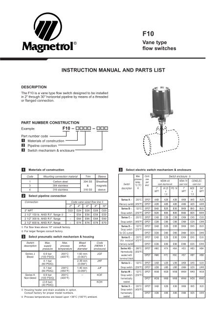
DESCRIPTION<br />
®<br />
F10<br />
Vane type<br />
flow switches<br />
INSTRUCTION MANUAL AND PARTS LIST<br />
The F10 is a vane type flow switch designed to be installed<br />
in 2" through 30" horizontal pipeline by means of a threaded<br />
or flanged connection.<br />
PART NUMBER CONSTRUCTION<br />
Example: F10 – –<br />
Part number code<br />
1 Materials of construction<br />
2 Pipeline connection<br />
3 Switch mechanism & enclosure<br />
1<br />
2<br />
Select pipeline connection<br />
Connection Code vane sized flow line ①<br />
2" 4" 6" 8" 10"<br />
2" NPT D22 D24 D26 D28 D20<br />
2 1/2" 150 lb. ANSI R.F. flange ② – E54 E56 E58 E50<br />
2 1/2" 300 lb. ANSI R.F. flange – E64 E66 E68 E60<br />
2 1/2" 600 lb. ANSI R.F. flange – E74 E76 E78 E70<br />
① For flow lines above 10" consult factory.<br />
② For larger flanges consult factory.<br />
3<br />
Materials of construction<br />
Code Mounting connection material Trim Sleeve<br />
1 Carbon steel 304 SS Sheathed<br />
3 304 stainless & magnetic<br />
4 316 stainless 316 SS sleeve<br />
Select pneumatic switch mechanism & housing<br />
Switch Max. Max. Bleed Code<br />
description supply process orifice (NEMA 1<br />
pressure temperature diameter enclosure)<br />
Series J 6.9 bar 200°C 1.60 mm JGF<br />
Bleed (100 PSIG) (400°F) (0.063")<br />
4.1 bar 2.39 mm JHF<br />
(60 PSIG) (0.094")<br />
4.1 bar 230°C 1.40 mm JJF<br />
(60 PSIG) (450°F) (0.055")<br />
Series K 6.9 bar 200°C – KOF<br />
Non-bleed (100 PSIG) (400°F)<br />
(2.8 bar)<br />
(40 PSIG)<br />
KOH<br />
③ Housing heater and drain available in option.<br />
Consult factory for proper model numbers.<br />
④ Process temperatures are based upon +38°C (100°F) ambient.<br />
3<br />
Select electric switch mechanism & enclosure<br />
Max.<br />
process<br />
temp.<br />
°C (°F)<br />
④<br />
Cont.<br />
one<br />
per<br />
encl.<br />
Switch enclosure ③<br />
NEMA 4X NEMA 7/9 CENELEC<br />
Switch cast aluminium cast iron cast iron<br />
description 1" M 20 PG 16 1" M20 3/4"<br />
NPT x NPT x NPT<br />
: 1.5 1.5<br />
Series A – 230°C SPDT AAB A2B A3B AKM AK5 AU5<br />
Mercury switch (450°F) DPDT ADB A8B A9B ANM AD5 AW5<br />
Series B – 120°C SPDT BAB B2B B3B BKM BK5 BU5<br />
Snap switch (250°F) DPDT BDB B8B B9B BNM BD5 BW5<br />
Series C – 230°C SPDT CAB C2B C3B CKM CK5 CU5<br />
Snap switch (450°F) DPDT CDB C8B C9B CNM CD5 CW5<br />
Series D – 120°C SPDT DAB D2B D3B DKM DK5 DU5<br />
Snap switch (250°F)<br />
for DC current DPDT DDB D8B D9B DNM DD5 DW5<br />
Series E – 230°C SPDT EAB E2B E3B EKM EK5 EU5<br />
Vibr. resistant (450°F)<br />
mercury switch DPDT EDB E8B E9B ENM ED5 EW5<br />
Series HS – 288°C SPDT HM2 H7A H6A HS3 HB3 HB4<br />
Hermetically (550°F)<br />
sealed with<br />
terminal block<br />
DPDT HM6 H7C H6C HS7 HB7 HB8<br />
Series U – 120°C SPDT UAB U2B U3B UKM UK5 UU5<br />
Snap switch (250°F) DPDT UDB U8B U9B UNM UD5 UW5<br />
Series W – 120°C SPDT WAB W2B W3B WKM WK5 WU5<br />
Snap switch (250°F)<br />
hermetically<br />
sealed<br />
DPDT WDB W8B W9B WNM WD5 WW5<br />
Series X – 230°C SPDT XAB X2B X3B XKM XK5 XU5<br />
Snap switch (450°F)<br />
hermetically<br />
sealed<br />
DPDT XDB X8B X9B XNM XD5 XW5
OPERATING PRINCIPLE<br />
The actuating vane is magnetically linked to a pivoted<br />
electric (or pneumatic) switch, which is isolated from the<br />
process by a non-magnetic barrier tube. As the actuating<br />
vane moves with an increase in flow, it drives a magnetic<br />
sleeve ① into the field of a permanent magnet ② located<br />
outside the barrier tube ③ which trips the switch. As flow<br />
decreases, the actuating vane returns to a vertical position,<br />
allowing the magnet and switch assembly to return to the<br />
“No Flow” position.<br />
UNPACKING<br />
Unpack the intrument carefully. Inspect all units for damage.<br />
Report any concealed damage to the carrier within 24 hours.<br />
Check the content of the packing slip and purchase order.<br />
Check and record the serial number for future reference<br />
when ordering parts.<br />
PIPING<br />
The F10 flow switch should be located in a horizontal run<br />
pipe with the arrow on the body bushing or mounting flange<br />
pointing in the direction of flow.<br />
MOUNTING — THREADED CONNECTION<br />
A. Installation of F10 IN LINE<br />
1. Insert a length of pipe in 2" 3,000 Ib. Threadolet fitting.<br />
2. Plumb the vertical center line of the fitting and trace<br />
around the fitting to locate center line of required 67 mm<br />
(2.62") ø hole (Figure 2).<br />
Figure 2<br />
3. Clean-up inside edges of hole and remove any slag on<br />
the bottom of line that could interfere with vane.<br />
4. With fitting concentrically positioned over the 67 mm<br />
(2.62") ø. hole and the vertical center line held plumb (as<br />
shown in Figure 3), tack weld the fitting at 4 equally<br />
space points. After tacking, remove 1.5 mm (0.06") ø<br />
spacer wire (Figure 2).<br />
Figure 3<br />
2<br />
67 ø (2.62")<br />
2" pipe,<br />
±305 mm (12") long<br />
1.5 mm (0.06") ø<br />
spacer wire to<br />
provide root cap<br />
(see note<br />
at right)<br />
Air bubble in<br />
level position<br />
Tack weld<br />
4 places<br />
Air bubble in<br />
level position<br />
Magnet<br />
INSTALLATION<br />
(3000 lb.)<br />
2" threadolet fitting<br />
Marker (note A2)<br />
Vertical centerline<br />
must be plumb<br />
Air bubble in<br />
level position<br />
Vertical centerline<br />
must be plumb<br />
Switch mechanism<br />
NO FLOW<br />
POSITION<br />
Adjusting screw<br />
Magnetic sleeve<br />
Actuating vane<br />
Figure 1<br />
POSITION WITH<br />
ACTUATING FLOW PRESENT<br />
MOUNTING — THREADED CONNECTION<br />
A. Installation of F10 in line (cont.)<br />
NOTE: A hole in the pipeline less than 67 mm (2.62") in<br />
diameter will limit travel of the pivoted vane. If this condition<br />
cannot be avoided, the width of the vane should be reduced<br />
to 38 mm (1.50") maximum.<br />
IMPORTANT: For installation in 2.00" pipe lines, disregard<br />
67 mm (2.62") dimension and use inside of<br />
Threadolet as template.<br />
5. Proper operation of the model F10 depends upon the<br />
vertical center line of the 2" NPT coupling being plumb<br />
within 3°; keep fitting plumb while welding the continuous<br />
passes according to threadolet manufacturers installation<br />
procedure.<br />
B. Positioning vane perpendicular to flow<br />
6. With large and small vanes unassembled, tighten thread<br />
the F10 body bushing into the coupling on the pipeline<br />
until one of the 3 decal flow arrows is pointing parallel<br />
with flow.<br />
7. Mark the bushing thread even with the top of the<br />
threadolet as a reference point for trimming vane to correct<br />
length. Remove 2 arrows not parallel with pipe.<br />
8. Remove F10 from pipeline.<br />
9. Check position of arrow stamped on vane support<br />
bracket. This arrow should be pointing parallel with the<br />
flow arrow on the body bushing (as shown in Figure 4).<br />
If arrows are not parallel, remove the three vane support<br />
bracket mounting screws and rotate bracket until<br />
the stamped arrow is pointing parallel with the flow<br />
arrow; replace mounting screws.<br />
Figure 4<br />
Adjusting screw<br />
safety retainer<br />
Flow arrow must be<br />
pointing parallel<br />
with the line flow<br />
Stamped arrow<br />
located on vane<br />
support bracket<br />
Pivot pin<br />
Small vane<br />
Large vane Flow<br />
1/4"NPT plug<br />
Adjusting screw<br />
Cover<br />
Switch<br />
(SPDT dry contact shown)<br />
Body bushing<br />
Reference mark (note B8)<br />
Vane support bracket with 3 mounting screws<br />
Top of 2" threadolet fitting<br />
*<br />
Electrical outlet<br />
5 (0.19)<br />
Top of pipeline<br />
* 40 ± 0.06 (1.56 ± 2)<br />
Dimension C<br />
Inside bottom of pipeline
MOUNTING — THREADED CONNECTION<br />
C. Trimming vane to fit line size<br />
10. The Model F10 is furnished as standard with vanes<br />
suitable for use on 2" through 30" pipelines. Assemble<br />
vane (or vanes) to F10 and trim according to applicable<br />
line size as follows:<br />
2.00" line (SCH.40) – Use small vane only (no cutting<br />
should be necessary).<br />
2.50" line – Use small vane with large vane trimmed to<br />
38 mm (1.50") wide (same as small vane) and length<br />
trimmed to dimension C less 5 mm (0.19"), as shown in<br />
Figure 5.<br />
3.00" line and larger – Use small vane with large vane<br />
length trimmed to dimension C less 5 mm (0.19"), as<br />
shown in Figure 5. Upon final assembly of trimmed<br />
vanes, firmly tighten 2 screws (item 27, page 7). It is<br />
recommended that the lower retaining screw be peened<br />
over on the threaded end.<br />
Reference mark<br />
(note B8 & D11)<br />
13<br />
(0.50)<br />
6 *<br />
(0.25)<br />
5 (0.19)<br />
(5) min.<br />
Top of threadolet<br />
40 (1.56)<br />
Bottom of pipeline<br />
Figure 5<br />
Dimension C<br />
* 19 (0.75)<br />
Dimension C<br />
D. Final Mounting of F10<br />
11. Apply sealing compound to body bushing threads.<br />
12. Thread F10 into threadolet fitting and tighten body<br />
bushing to the same seal tight position as in note B6, so<br />
that the flow arrow is pointing parallel with the line flow.<br />
13. Connect power lines.<br />
INSTALLATION (cont.)<br />
MOUNTING — FLANGED CONNECTIONS<br />
Figure 6 shows 1 method which may be used to mount the<br />
Model F10 flow switch to 2 1/2" through 30" run pipes.<br />
Before final welding, alignment of mounting flange should<br />
be checked to be certain it is plumb. Finished mounting<br />
must allow control switch housing to be within 3° degrees<br />
of vertical for proper operation. A 3° slant is noticeable by<br />
eye, but installation should be checked with a spirit level.<br />
Flow<br />
①<br />
2 1/2" PS ANSI flange<br />
②<br />
2 1/2" PS pipe nipple<br />
(Sched. 80 max. wall thickness)<br />
2 1/2" 3000 lb.<br />
sockolet fitting<br />
③<br />
Actuating vane<br />
Figure 6<br />
Vertical centerline must be plumb<br />
2 1/2" ANSI<br />
mounting flange<br />
133 (2.25)<br />
④<br />
Top of run pipe<br />
76 (3) ø hole in run pipe<br />
⑤<br />
5 (0.19) min.<br />
Inside bottom<br />
of run pipe<br />
① Electrical outlet may be rotated 360° for wiring<br />
convenience.<br />
② Flange to match flange of F10 flow switch and<br />
positioned with bolt holes straddling center lines.<br />
③ For proper attachment procedure, refer to fitting<br />
manufacturer’s recommendation.<br />
④ Dimension shown is for use with 1.5 mm (0.06") thick<br />
flange gasket. If thicker gasket is used, reduce<br />
dimension amount equal to additional thickness.<br />
⑤ For run pipe sizes over 2 1/2" P.S. only. For installation<br />
on 2 1/2" run pipes, disregard 3" dimension and use<br />
inside of adaptor fitting as template.<br />
⑥ Follow sections B and C of MOUNTING — THREADED<br />
CONNECTION to position the vane perpendicular to<br />
the flow and trim the vane to size.<br />
3
WIRING<br />
NOTE: All Model F10 switch housings are designed to<br />
allow 360° positioning of the electrical outlet(s) for wiring<br />
convenience by loosening the set screw(s) located under<br />
the housing base.<br />
1. On high temperature applications (above 120°C (250°F)<br />
in pipeline), high temperature wire should be used<br />
between <strong>Magnetrol</strong> control and first junction box<br />
located in a cooler area.<br />
2. To gain access to switch mechanism, remove switch<br />
housing cover.<br />
3. Pull in supply wires (conductors), wrap them around<br />
enclosing tube beneath the baffle plate and connect to<br />
proper terminals. Check to be certain that excess wire<br />
does not interfere with “tilt” of switch and that adequate<br />
clearance exists for replacement of switch housing<br />
cover.<br />
4. Connect power supply to control and test switch<br />
actuation by varying flow rate within pipeline.<br />
NOTE: If switch mechanism fails to function properly,<br />
check vertical alignment of control housing and refer to<br />
installation bulletin on mechanism furnished, as listed below.<br />
5. Replace switch housing cover.<br />
NOTE: NEMA 7/9 housings, the housings must be “sealed”<br />
at the electrical outlet with suitable compound to prevent<br />
entrance of air. Check cover to base fit to be certain<br />
gasketed joint is tight. A positive seal is necessary to<br />
prevent infiltration of moisture laden air or corrosive gases<br />
into switch housing.<br />
6. Place flow switch into service.<br />
Switch mechanism Bulletin n° Series ref.<br />
Mercury switches A 42-783<br />
Dry contact switches B, C, D, U, W,X<br />
Anti-vibration mercury switches E<br />
Bleed type pneumatic valve J 42-685<br />
Non-bleed type pneumatic valve K 42-686<br />
4<br />
INSTALLATION (cont.)<br />
SWITCH ACTUATION ADJUSTMENT<br />
The Model F10 flow switch is factory set to actuate at the<br />
minimum flow rate. Actuation flow rate can be increased<br />
while the unit is in service (under pressure) by removing<br />
the 1/4” NPT plug to gain access to the “O” ring sealed<br />
adjusting screw. Each clockwise turn of the adjusting screw<br />
increases the actuating flow rate approximately 10% of the<br />
range of the specific flow vane being used.<br />
CAUTION: The safety retainer above the adjusting<br />
screw is there to help prevent the accidental removal<br />
of the adjusting screw. Do not defeat its purpose by<br />
forcefully backing out the adjustment screw. Be sure<br />
to replace 1/4” NPT plug and tighten firmly.
Line size Dim. X max. Equivalent<br />
max. wall schedule<br />
2" 46 (1.81) 180<br />
2 1/2" 49 (1.94) 160<br />
3" 48 (1.88) 180<br />
3 1/2" 48 (1.88) 180<br />
4" 51 (2.00) 120<br />
5" 52 (2.06) 120<br />
6" 54 (2.12) 120<br />
8" 56 (2.19) 100<br />
over 8" 59 (1.31) 1—<br />
Electrical connections E<br />
Electrical switches:<br />
NEMA 4X: 1" NPT – M20 x 1,5 – PG 16<br />
(2 entries – 1 plugged)<br />
NEMA 7/9: 1" NPT-F entry<br />
CENELEC: M 20 x 1,5 or 3/4"NPT-F entry<br />
Pneumatic switches:<br />
K series: 1/4" NPT-F (2 entries)<br />
J series: 1/4" NPT-F (1 entry)<br />
OUTLINE DIMENSIONS<br />
Housing Threaded mounting<br />
A B C D<br />
NEMA 4X 10⁸ 151 314 48<br />
(4.29) (5.93) (12.38) (1.88)<br />
NEMA 7/9 100 143 336 42<br />
(3.94) (5.63) (13.23) (1.65)<br />
CENELEC 110 143 339 45<br />
(4.33) (5.63) (13.35) (1.77)<br />
Pneum. sw. J 110 118 306 39<br />
(4.33) (4.64) (12.05) (1.53)<br />
Pneum. sw. K 130 118 306 39<br />
(5.12) (4.64) (12.05) (1.53)<br />
Housing Flanged mounting<br />
A B C D<br />
NEMA 4X 10⁸ 151 257 48<br />
(4.29) (5.93) (10.12) (1.88)<br />
NEMA 7/9 100 143 246 42<br />
(3.94) (5.63) (9.68) (1.65)<br />
CENELEC 110 143 249 45<br />
(4.33) (5.63) (9.80) (1.77)<br />
Pneum. sw. J 110 118 216 39<br />
(4.33) (4.64) (8.50) (1.53)<br />
Pneum. sw. K 130 118 216 39<br />
(5.12) (4.64) (8.50) (1.53)<br />
SPECIFICATIONS<br />
Rotation clearance<br />
"X"<br />
E<br />
D<br />
40 ± 2<br />
(1.56 ± 0.06)<br />
Rotation clearance<br />
Pipe line size<br />
(horizontal lines only)<br />
A<br />
E C<br />
A<br />
D<br />
133<br />
(5.25)<br />
187<br />
(7.38)<br />
Model F10 flow switch<br />
with flanged connection<br />
Flow vane<br />
B<br />
FLOW<br />
B<br />
Model F10 flow switch<br />
with threaded connection<br />
62 ø ± 2<br />
(2.56 ø ± 0.06)<br />
C<br />
Vane width<br />
76 ø (3.00)<br />
5 (0.19) min.<br />
44<br />
(1.75)<br />
38<br />
(1.50)<br />
2 1/2" ANSI flange<br />
(to match F10)<br />
2" NPT<br />
2 1/2" ANSI<br />
mounting flange<br />
2" NPT 3000# bonney<br />
threadolet or equal<br />
(supplied by customer)<br />
191 (7.50) – length<br />
furnished unless<br />
otherwise specified<br />
3" pipe and up<br />
2" and 2 1/2" pipe<br />
5
IMPORTANT:<br />
When ordering, please specify:<br />
A. Model and serial number of control.<br />
B. Name and Number of replacement assembly.<br />
NOTE: Consult factory for CENELEC housing.<br />
6<br />
REPLACEMENT PARTS<br />
Item Description Qty. Carbon T304 SS T316 SS Forged T304 SS T316 SS<br />
no. steel mounting mounting mounting steel flange flange flange<br />
1 Switch housing cover 1 See bulletin 42-780 for switch housings, items 2 & 3 only applicable on steel NEMA 4 housing,<br />
4 Switch housing base 1 see bulletin 42-680.<br />
5 1/4-20 set screw 1 (item 2: head screw — item 3: retaining washer)<br />
6 Switch mechanism 1 See appropriate bulletin on switch mechanism (listed on page 4)<br />
7 Baffle plate assembly 1 36-5303-001<br />
8 6-32 round head screw 1 10-1409-005<br />
9 1/4-20 NPT plug 1 E-tube kit E-tube kit E-tube kit E-tube kit E-tube kit E-tube kit<br />
10 Safety retainer 1 89-5912-001 89-5913-001 189-5914-001 189-5928-001 89-5929-001 189-5930-001<br />
11 Washer 1<br />
12 “O” ring 1<br />
13 Adjustment screw 1<br />
14 Enclosing tube 1<br />
15 Enclosing tube gasket 1 12-1204-001<br />
16a Body bushing 1 089-5704-001 089-5705-001 189-5706-001 —<br />
16b Stem. cam 150 lb. 1 — 32-7203-001 32-7204-001 32-7205-001<br />
follower, and 300 lb. 32-7203-002 32-7204-002 32-7205-002<br />
flange assembly 600 lb. 32-7203-003 32-7204-003 32-7205-003<br />
17 Flow arrow 1 05-9822-001 —<br />
18 Upper spring guide 1 Stem Stem Attraction sleeve Attraction<br />
19 Range spring 1 kit kit and sleeve and<br />
20 10-32 hex nut 3 89-5541-001 189-5542-001 spring kit spring kit<br />
21 Lower spring guide 1 189-5544-001 189-5545-001<br />
22 Attraction sleeve 1<br />
23 Drain washer 1<br />
24 Stem assembly 1 —<br />
25 No. 8 lockwasher 3<br />
26 8-32 fil. hd. screw 3<br />
27 8-32 rd. hd. screw 2 Vane kit 89-6703-001<br />
28 Small vane 1 Vanes for pipe runs over 8" are special order items. See important order note below.<br />
29 Large vane<br />
30 <strong>Instruction</strong> tag (not shown) 1 05-9816-001
REPLACEMENT PARTS (cont.)<br />
Threaded mounting Flanged mounting<br />
Serial number<br />
tage<br />
(ref.)<br />
7
AGENCY APPROVALS<br />
Agency Approval<br />
CENELEC EEx d II C T6 (IP 66) explosion proof<br />
EEx ia II C T6 intrinsically safe ①<br />
CSA ➀ Non-hazardous NEMA 4X (IP 65)<br />
Class I, Div. 2, Groups A, B, C & D<br />
Class I, Div. 1, Groups C & D<br />
Class II, Div. 1, Groups E, F & G<br />
Class I, Div. 1, Groups B, C & D<br />
Class II, Div. 1, Groups E, F & G<br />
FM ➀ Non-Hazardous NEMA 4X (IP 65)<br />
Class I, Div. 1, Groups C & D<br />
Class II, Div. 1, Groups E, F & G<br />
Class I, Div. 1, Groups A, B, C & D<br />
Class II, Div. 1, Groups E, F & G<br />
SAA ➀ Ex d II C T6 (IP 65)<br />
① Consult factory for proper model numbers.<br />
IMPORTANT<br />
SERVICE POLICY<br />
Owners of <strong>Magnetrol</strong> products may request the return of a control; or, any part of a control for complete rebuilding or<br />
replacement. They will be rebuilt or replaced promptly. <strong>Magnetrol</strong> <strong>International</strong> will repair or replace the control, at no cost to<br />
the purchaser, (or owner) other than transportation cost if:<br />
a. Returned within the warranty period; and,<br />
b. The factory inspection finds the cause of the malfunction to be defective material or workmanship.<br />
If the trouble is the result of conditions beyond our control; or, is NOT covered by the warranty, there will be charges for labour<br />
and the parts required to rebuild or replace the equipment.<br />
In some cases, it may be expedient to ship replacement parts; or, in extreme cases a complete new control, to replace the<br />
original equipment before it is returned. If this is desired, notify the factory of both the model and serial numbers of the<br />
control to be replaced. In such cases, credit for the materials returned, will be determined on the basis of the applicability of<br />
our warranty.<br />
No claims for misapplication, labour, direct or consequential damage will be allowed.<br />
RETURNED MATERIAL PROCEDURE<br />
So that we may efficiently process any materials that are returned, it is essential that a “Return Material Authorisation” (RMA)<br />
form will be obtained from the factory. It is mandatory that this form will be attached to each material returned. This form is<br />
available through <strong>Magnetrol</strong>’s local representative or by contacting the factory. Please supply the following information:<br />
1. Purchaser Name<br />
2. Description of Material<br />
3. Serial Number<br />
4. Desired Action<br />
5. Reason for Return<br />
6. Process details<br />
All shipments returned to the factory must be by prepaid transportation. <strong>Magnetrol</strong> will not accept collect shipments.<br />
All replacements will be shipped FOB factory.<br />
BULLETIN N°: BE 47-602.14<br />
EFFECTIVE: AUGUST 1995<br />
UNDER RESERVE OF MODIFICATIONS SUPERSEDES: July 1991<br />
®<br />
BELGIUM Heikensstraat 6, 9240 Zele<br />
Tel. (052) 45.11.11 Fax (052) 45.09.93<br />
DEUTSCHLAND Schloßstraße 76, D-51429 Bergisch Gladbach-Bensberg<br />
Tel. (02204) 9536-0 Fax (02204) 9536-53<br />
FRANCE 11, Rue A. Einstein, Espace Descartes, 77420 Champs-sur-Marne<br />
adresse postale: 77436 Marne-la-Vallée Cédex 2<br />
Tel. (0) 164.68.58.28 Fax (0) 164.68.58.27<br />
ITALIA Via Arese 12, I-20159 Milano<br />
Tel. (02) 607.22.98 (R.A.) Fax (02) 668.66.52<br />
UNITED Unit 1 Regent Business Centre<br />
KINGDOM Jubilee Road Burgess Hill West Sussex RH 15 9TL<br />
Tel. (01444) 871313 Fax (01444) 871317<br />
INDIA B4/115 Safdurjung Enclave, New Delhi 110 029<br />
Tel. 91 (11) 6186211 Fax 91 (11) 6186418