Instruction Manual - Magnetrol International
Instruction Manual - Magnetrol International
Instruction Manual - Magnetrol International

You also want an ePaper? Increase the reach of your titles
YUMPU automatically turns print PDFs into web optimized ePapers that Google loves.
DESCRIPTION<br />
®<br />
INSTRUCTION MANUAL AND PARTS LIST<br />
B73 instruments are float operated liquid level controls<br />
designed for external float cage mounting.<br />
These instruments are ideally used for off-on liquid level<br />
control, alarm and safety shut-down service in a wide variety<br />
of applications including large steam-electric generating<br />
stations, oil refineries and chemical processing operations.<br />
The B73 is available with either a carbon steel or stainless<br />
steel float cage and is suitable for service pressure ratings<br />
up to 20.7 bar (300 PSIG) and specific gravity ratings down<br />
to 0.60.<br />
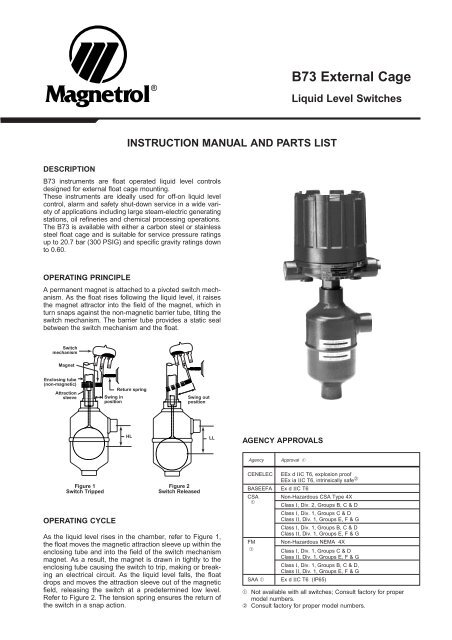
OPERATING PRINCIPLE<br />
A permanent magnet is attached to a pivoted switch mechanism.<br />
As the float rises following the liquid level, it raises<br />
the magnet attractor into the field of the magnet, which in<br />
turn snaps against the non-magnetic barrier tube, tilting the<br />
switch mechanism. The barrier tube provides a static seal<br />
between the switch mechanism and the float.<br />
Switch<br />
mechanism<br />
Magnet<br />
Enclosing tube<br />
(non-magnetic)<br />
Attraction<br />
sleeve<br />
4 5 6<br />
Figure 1<br />
Switch Tripped<br />
OPERATING CYCLE<br />
Return spring<br />
Swing in<br />
position<br />
4 5 6<br />
Swing out<br />
position<br />
HL LL<br />
Figure 2<br />
Switch Released<br />
As the liquid level rises in the chamber, refer to Figure 1,<br />
the float moves the magnetic attraction sleeve up within the<br />
enclosing tube and into the field of the switch mechanism<br />
magnet. As a result, the magnet is drawn in tightly to the<br />
enclosing tube causing the switch to trip, making or breaking<br />
an electrical circuit. As the liquid level falls, the float<br />
drops and moves the attraction sleeve out of the magnetic<br />
field, releasing the switch at a predetermined low level.<br />
Refer to Figure 2. The tension spring ensures the return of<br />
the switch in a snap action.<br />
AGENCY APPROVALS<br />
Agency Approval ➀<br />
B73 External Cage<br />
Liquid Level Switches<br />
CENELEC EEx d IIC T6, explosion proof<br />
EEx ia IIC T6, intrinsically safe ➁<br />
BASEEFA Ex d IIC T6<br />
CSA Non-Hazardous CSA Type 4X<br />
➀<br />
Class I, Div. 2, Groups B, C & D<br />
Class I, Div. 1, Groups C & D<br />
Class II, Div. 1, Groups E, F & G<br />
Class I, Div. 1, Groups B, C & D<br />
Class II, Div. 1, Groups E, F & G<br />
FM Non-Hazardous NEMA 4X<br />
➀ Class I, Div. 1, Groups C & D<br />
Class II, Div. 1, Groups E, F & G<br />
Class I, Div. 1, Groups B, C & D,<br />
Class II, Div. 1, Groups E, F & G<br />
SAA ➀ Ex d IIC T6 (IP65)<br />
➀ Not available with all switches; Consult factory for proper<br />
model numbers.<br />
➁ Consult factory for proper model numbers.
MODEL IDENTIFICATION<br />
A complete B73 switch, consists of 1 code:<br />
2<br />
Pneumatic switch Max. supply pressure Max. liquid temperature Bleed orifice Ø Code (NEMA 3R encl.)<br />
description bar (PSIG) °C (°F) mm (inches) mat'l. code 1 mat'l. code 2, 4<br />
Series J bleed type 6.9 bar (100 PSIG) 200°C (400°F) 1.60 mm (0.063") JDG JDE<br />
4.1 bar (160 PSIG) 200°C (400°F) 2.39 mm (0.094") JEG JEE<br />
4.1 bar (160 PSIG) 230°C (450°F) 1.40 mm (0.055") JFG JFE<br />
Series K non bleed type 6.9 bar (100 PSIG) 200°C (400°F) — — KOE<br />
2.8 bar (140 PSIG) 200°C (400°F) — KOG —<br />
SELECT ELECTRIC SWITCH MECHANISM & ENCLOSURE ➁<br />
Switch<br />
Description<br />
MATERIALS OF CONSTRUCTION<br />
1 Carbon steel cage with 316 SST float and 400 SST magnetic sleeve.<br />
2 Carbon steel cage with 316 SST float, magnetic sleeve with 316 SST jacket.<br />
4 316 SST cage and trim and float.<br />
Max.<br />
process<br />
temp.<br />
°C (°F)<br />
③<br />
SIZE AND TYPE OF PROCESS CONNECTION<br />
B 2 0 1" NPT threaded connection upper side/bottom<br />
B 3 0 1" NPT socket weld connection upper side/bottom<br />
1" ANSI type NW 25 DIN FORM C (DIN 2526) ▼ FLANGE TYPE & SIZE<br />
150 lbs 300 lbs ND 16 (DIN 2533) ND 25 (DIN 2534) ▼ MOUNTING STYLE<br />
N30 N40 1FA 1GA flanged connection upper side/bottom<br />
S30 S40 1FB 1GB flanged connection side/side<br />
Cont.<br />
one<br />
per<br />
encl.<br />
Switch mechanism and enclosure, refer to table below for pneumatic switch mechanisms and for<br />
electric switch mechanisms.<br />
B 7 3 complete code for B73 liquid float level switch<br />
SELECT PNEUMATIC SWITCH MECHANISM & ENCLOSURE<br />
1"<br />
NPT<br />
All models with material of construction code 1 All models with material of construction codes 2 and 4<br />
NEMA 4X NEMA 7/9 BASEEFA CENELEC NEMA 4X NEMA 7/9 BASEEFA CENELEC<br />
cast aluminium cast iron cast iron cast iron cast aluminium cast iron cast iron cast iron<br />
M 20<br />
1"<br />
M20<br />
3/4"<br />
M20<br />
3/4" 1"<br />
M 20<br />
1"<br />
M20<br />
3/4"<br />
M20<br />
x PG 16 x x x PG 16 x x<br />
1.5<br />
NPT<br />
1.5<br />
NPT<br />
1.5<br />
NPT NPT<br />
1.5<br />
NPT<br />
1.5<br />
NPT<br />
1.5<br />
Series A – 230°C SPDT AAP A2P A3P AKR AK8 AU8 AK7 AU7 AAQ A2Q A3Q AKY AK6 AU6 AK5 AU5<br />
Mercury switch (450°F) DPDT ADP A8P A9P ANR AN8 AX8 AD7 AW7 ADQ A8Q A9Q ANY AN6 AX6 AD5 AW5<br />
Series B – 120°C SPDT BAP B2P B3P BKR BK8 BU8 BK7 BU7 BAQ B2Q B3Q BKY BK6 BU6 BK5 BU5<br />
Snap switch (250°F) DPDT BDP B8P B9P BNR BN8 BX8 BD7 BW7 BDQ B8Q B9Q BNY BN6 BX6 BD5 BW5<br />
Series C – 230°C SPDT CAP C2P C3P CKR CK8 CU8 CK7 CU7 CAQ C2Q C3Q CKY CK6 CU6 CK5 CU5<br />
Snap switch (450°F) DPDT CDP C8P C9P CNR CN8 CX8 CD7 CW7 CDQ C8Q C9Q CNY CN6 CX6 CD5 CW5<br />
Series D –<br />
Snap switch<br />
120°C<br />
(250°F)<br />
SPDT – – – – – – – – DAQ D2Q D3Q DKY DK6 DU6 DK5 DU5<br />
for DC<br />
current appl.<br />
DPDT – – – – – – – – DDQ D8Q D9Q DNY DN6 DX6 DD5 DW5<br />
Series E –<br />
Vibration<br />
230°C<br />
(450°F)<br />
SPDT EAP E2P E3P EKR EK8 EU8 EK7 EU7 EAQ E2Q E3Q EKY EK6 EU6 EK5 EU5<br />
resistant<br />
mercury switch<br />
DPDT EDP E8P E9P ENR EN8 EX8 ED7 EW7 EDQ E8Q E9Q ENY EN6 EX6 ED5 EW5<br />
Series F – 230°C<br />
Snap switch (450°F) SPDT FAP F2P F3P FKR FK8 FU8 FK7 FU7 FAQ F2Q F3Q FKY FK6 FU6 FK5 FU5<br />
hermetically<br />
sealed<br />
DPDT FDP F8P F9P FNR FN8 FX8 FD7 FW7 FDQ F8Q F9Q FNY FN6 FX6 FD5 FW5<br />
Series HS –<br />
Snap switch<br />
hermetically<br />
230°C<br />
(450°F)<br />
SPDT – – – – – – – – HM2 H7A H6A HS3 HB1 HB2 HB3 HB4<br />
sealed with<br />
terminal block<br />
DPDT – – – – – – – – HM6 H7C H6C HS7 HB5 HB6 HB7 HB8<br />
Series U – 120°C SPDT UAP U2P U3P UKR UK8 UU8 UK7 UU7 UAQ U2Q U3Q UKY UK6 UU6 UK5 UU5<br />
Snap switch (250°F) DPDT UDP U8P U9P UNR UN8 UX8 UD7 UW7 UDQ U8Q U9Q UNY UN6 UX6 UD5 UW5<br />
Series W –<br />
Snap switch<br />
230°C<br />
(450°F)<br />
SPDT WAP W2P W3P WKR WK8 WU8 WK7 WU7 WAQ W2Q W3Q WKY WK6 WU6 WK5 WU5<br />
hermetically<br />
sealed<br />
DPDT – – – – – – – – WDQ W8Q W9Q WNY WN6 WX6 WD5 WW5<br />
Series X –<br />
Snap switch<br />
230°C<br />
(450°F)<br />
SPDT XAP X2P X3P XKR XK8 XU8 XK7 XU7 XAQ X2Q X3Q XKY XK6 XU6 XK5 XU5<br />
hermetically<br />
sealed<br />
DPDT – – – – – – – – XDQ X8Q X9Q XNY XN6 XX6 XD5 XW5<br />
➁ Housing heater and drain available in option. Consult factory for proper<br />
model numbers.<br />
▼<br />
3/4"<br />
NPT<br />
③ Max. Process temperatures are based on 38°C (100°F) ambient temperature.
CRITICAL ALARM FUNCTION<br />
It is recommended that for critical alarm functions, an additional<br />
level switch be installed as a high-high or low-low<br />
level alarm for maximum protection.<br />
PIPING<br />
Figure 3 shows a typical piping installation of a <strong>Magnetrol</strong><br />
level switch to a pressure vessel. Reference mark on float<br />
chamber should be aligned to correspond with liquid level<br />
in vessel at which switch control is desired.<br />
Use pipe of sufficient strength to support the control. If necessary,<br />
provide a stand or hanger to help support its<br />
weight. All piping should be straight and free of “low spots”<br />
or “pockets” so that lower liquid line will drain towards the<br />
vessel and upper vapor line will drain toward the control.<br />
Shut-off valves are recommended for installation between<br />
the vessel and the control. If control is to be used with a<br />
lower temperature liquid (one which will “boil” in the float<br />
chamber if outside heat is absorbed), the chamber and piping<br />
should be insulated. Such boiling in the chamber will<br />
cause false level indications. DO NOT INSULATE SWITCH<br />
MECHANISM HOUSING.<br />
On controls equipped with pneumatic switch assemblies,<br />
consult bulletin on mechanism furnished for air (or gas) piping<br />
instructions. Refer to chart on this page for bulletin numbers<br />
for pneumatic switches.<br />
Most mechanical control switch housings are designed to<br />
allow 360° positioning of the cable entries by loosening the<br />
set screw(s). See figure 4. On high temperature applications<br />
(above 120° C [250° F]), high temperature wire should<br />
be used between control and first junction box located in a<br />
cooler area.<br />
1. To gain access to switch mechanism(s) remove switch<br />
housing cover. (See CAUTION next page.)<br />
2. Pull in supply wires (conductors), wrap them around<br />
enclosing tube under the baffle plate and connect to<br />
proper terminals. Be certain that excess wire does not<br />
interfere with "tilt" of switch and that adequate clearance<br />
exists for replacement of switch housing cover.<br />
NOTE: See bulletin on switch mechanism furnished with<br />
your control (as listed below) for proper connections.<br />
3. Connect power supply to control and test switch action<br />
by varying liquid level in tank or vessel.<br />
CAUTION:<br />
In hazardous area, do not power the unit until<br />
the cable gland is sealed and the enclosure<br />
cover is screwed down securely.<br />
INSTALLATION<br />
WIRING<br />
MOUNTING<br />
cable entry<br />
Switch<br />
actuating<br />
level<br />
reference<br />
marks<br />
Drain<br />
valve<br />
Shutoff<br />
valve<br />
Max<br />
305 mm<br />
Figure 3<br />
Pressure<br />
vessel<br />
Adjust piping as required to bring control to a vertical position.<br />
<strong>Magnetrol</strong> controls must be mounted within three (3°)<br />
degrees of vertical. A three degree slant is noticeable by<br />
eye, but installation should be checked with a spirit level on<br />
top and/or sides of float chamber.<br />
Controls should be mounted as close to the vessel as possible.<br />
This will result in a more responsive and accurate<br />
level change in the control. Liquid in a long line may be<br />
cooler and more dense than liquid in the vessel causing<br />
lower level indication in the control than actual level in the<br />
vessel.<br />
NOTE: If switch mechanism fails to function properly, check<br />
vertical alignment of control housing and consult installation<br />
instructions in switch mechanism bulletin.<br />
4. Replace switch housing cover and place control into service.<br />
NOTE: If control has been furnished with an explosion proof<br />
(cast) or moisture proof (gasketed) switch housing, check<br />
the following:<br />
– After wiring connections have been completed, housings<br />
must be sealed via the correct cable gland to prevent<br />
entrance of air.<br />
– Check cover to base fit, to be certain gasketed joint is<br />
tight. A positive seal is necessary to prevent infiltration of<br />
moisture laden air or corrosive gases into switch housing.<br />
Switch mechanism Bulletin Reference series<br />
Mercury switches 42-783 A<br />
Dry contact switches 42-683 B, C, D, U, W, X<br />
Anti-vibration mercury switches E<br />
Anti-vibration dry contact switches 42-684 G, H, I<br />
Bleed type pneumatic valve 42-685 J<br />
Non-bleed type pneumatic valve 42-686 K<br />
3
Periodic inspections are a necessary means to keep your <strong>Magnetrol</strong> level control in good working order. This control<br />
is, in reality, a safety device to protect the valuable equipment it serves. Therefore, a systematic program of<br />
“Preventive Maintenance” should be implemented when control is placed into service. If the following sections on<br />
“What to Do” an “What to Avoid” are observed, your control will provide reliable protection of your capital equipment.<br />
WHAT TO DO<br />
1. Keep Control Clean<br />
Be sure the switch housing cover is always in place on<br />
the control. This cover is designed to keep dust and dirt<br />
from interfering with switch mechanism operation. In<br />
addition, it protects against damaging moisture and<br />
acts as a safety feature by keeping bare wires and terminals<br />
from being exposed. Should the housing cover<br />
become damaged or misplaced, order a replacement<br />
immediately.<br />
2. Inspect Switch Mechanisms, Terminals and<br />
Connections Monthly<br />
–Mercury switches may be visually inspected for short<br />
circuit damage. Check for small cracks in the glass<br />
tube containing the mercury. Such cracks can allow<br />
entrance of air into the tube causing the mercury to<br />
“oxidize”. This is noticeable as the mercury will<br />
appear dirty and have a tendency to “string out” like<br />
water, instead of breaking into clean round pools. If<br />
these conditions exist, replace the mercury switch<br />
immediately.<br />
–Dry contact switches should be inspected for excessive<br />
wear on actuating lever or misalignment of<br />
adjusting screw at point of contact between screw<br />
and lever. Such wear can cause false switch actuating<br />
levels. Adjust switch mechanism to compensate<br />
(if possible) or replace switch.<br />
4<br />
WIRING (cont.)<br />
OBSERVE ALL APPLICABLE ELECTRICAL CODES AND PROPER WIRING PROCEDURES<br />
NEMA 4x<br />
NEMA 7/9<br />
Set screw<br />
Set screw<br />
Figure 4a<br />
Set screw<br />
Position<br />
screw<br />
Figure 4b<br />
CENELEC/BASEEFA<br />
Locking screw<br />
PREVENTIVE MAINTENANCE<br />
Figure 4c<br />
CAUTION:<br />
- DO NOT attempt to reposition NEMA 4 /<br />
NEMA 7/9 housings without loosening the<br />
set screws; CENELEC/BASEEFA housings<br />
MAY NOT BE REPOSITIONNED. ALWAYS<br />
retighten set screw(s) after repositionning.<br />
- DO NOT attempt to unscrew cover of CEN-<br />
ELEC/BASEEFA housings before loosening<br />
locking screw in base of housing. ALWAYS<br />
retighten locking screw after replacing cover.<br />
DO NOT operate your control with defective maladjusted<br />
switch mechanisms (refer to bulletin on switch mechanism<br />
furnished for service instructions).<br />
–<strong>Magnetrol</strong> controls may sometimes be exposed to<br />
excessive heat or moisture. Under such conditions,<br />
insulation on electrical wires may become brittle,<br />
eventually breaking or peeling away. The resulting<br />
“bare” wires can cause short circuits. Check wiring<br />
carefully and replace at first sign of brittle insulation.<br />
–Vibration may sometimes cause terminal screws to<br />
work loose. Check all terminal connections to be certain<br />
that screws are tight.<br />
–On units with pneumatic switches, air (or gas) operating<br />
medium lines subjected to vibration, may eventually<br />
crack or become loose at connections causing<br />
leakage. Check lines and connections carefully and<br />
repair or replace, if necessary.<br />
NOTE: As a matter of good practice, spare switches should<br />
be kept on hand at all times.<br />
3. Inspect Entire Unit Periodically<br />
Isolate control from vessel. Raise and lower liquid level<br />
to check for switch contact and reset.
WHAT TO AVOID<br />
PREVENTIVE MAINTENANCE (cont.)<br />
1. NEVER leave switch housing cover off the control<br />
longer than necessary to make routine inspections.<br />
2. NEVER place a jumper wire across terminals to “cutout”<br />
the control. If a “jumper” is necessary for test purposes,<br />
be certain it is removed before placing control<br />
into service.<br />
Usually the first indication of improper operation is failure of<br />
the controlled equipment to function i.e. pump will not start<br />
(or stop); signal lamps fail to light, etc. When these symptoms<br />
occur, whether at time of installation or during routine<br />
service thereafter, check the following potential external<br />
causes first.<br />
– Fuses may be blown.<br />
– Reset button(s) may need resetting.<br />
– Power switch may be open.<br />
– Controlled equipment may be faulty.<br />
– Wiring or medium lines leading to control may be<br />
defective.<br />
If a thorough inspection of these possible conditions fails to<br />
locate the trouble, proceed next to a check of the controls<br />
switch mechanism.<br />
CHECK SWITCH MECHANISM<br />
1. Pull disconnect switch or otherwise assure disconnect<br />
power to the control.<br />
2. Remove switch housing cover.<br />
3. Disconnect power wiring from switch assembly.<br />
4. Swing magnet assembly in and out by hand to check<br />
carefully for any sign of binding. Assembly should<br />
require minimal force to move it through its full swing.<br />
5. If binding exists, magnet may be rubbing enclosing tube.<br />
If magnet is rubbing, loosen magnet clamp screw and<br />
shift magnet position. Retighten magnet clamp screw.<br />
6. If switch magnet assembly swings freely and mechanism<br />
still fails to actuate, check installation of control to be<br />
certain it is within the specified three (3°) degrees of vertical<br />
(use spirit level on side of enclosing tube in two<br />
places, 90° apart).<br />
7. If mechanism is equipped with a mercury switch, examine<br />
glass mercury tube closely as previously described<br />
in “Preventive Maintenance” section. If switch is damaged,<br />
replace it immediately.<br />
8. If switch mechanism is operating satisfactorily, proceed<br />
to check sensing unit.<br />
TROUBLE SHOOTING<br />
3. NEVER attempt to make adjustments or replace switches<br />
without reading instructions carefully. Certain adjustments<br />
provided for in <strong>Magnetrol</strong> controls should not be<br />
attempted in the field. When in doubt, consult the factory<br />
or your local <strong>Magnetrol</strong> representative.<br />
4. NEVER use lubricants on pivots of switch mechanisms.<br />
A sufficient amount of lubricant has been applied at the<br />
factory to ensure a lifetime of service. Further oiling is<br />
unnecessary and will only tend to attract dust and dirt<br />
which can interfere with mechanism operation.<br />
CHECK SENSING UNIT<br />
1. Check to be certain liquid is entering float chamber. A<br />
valve may be closed or piping plugged.<br />
2. Proceed to check level sensing action.<br />
CAUTION: Unit must be normalized to atmospheric<br />
pressure before removing switch housing assembly.<br />
3. Remove the switch housing assembly by loosening the<br />
enclosing tube nut located immediately below the housing<br />
base.<br />
4. Inspect attraction sleeve(s) and inside of enclosing tube<br />
for excessive corrosion or solids build-up which could<br />
restrict movement, preventing sleeve(s) from reaching<br />
field of magnet(s).<br />
5. Fill chamber with liquid at room pressure. Check float(s)<br />
to be certain it is buoyant in the liquid (float chamber<br />
must have adequate liquid level). If float is determined to<br />
be filled with liquid or collapsed, entire float chamber<br />
assembly (sensing unit) should be replaced.<br />
CHECK COMPLETE UNIT<br />
Reassemble the unit. Reconnect the power supply and<br />
carefully actuate the switch mechanism manually (using a<br />
non-conductive tool) to determine whether controlled<br />
equipment will operate.<br />
CAUTION: With electrical power “on”, care should be<br />
taken to avoid contact with switch leads and connections<br />
at terminal block.<br />
If all components in the control are in operating condition,<br />
the trouble must be (and should be) located external to the<br />
control. Repeat inspection of external conditions previously<br />
described.<br />
NOTE: If difficulties are encountered which can not be<br />
identified, consult with the factory or your local representative<br />
for assistance. A complete description of the trouble<br />
should be provided along with information concerning your<br />
piping and mounting arrangement, plus a description of<br />
your operation sequence. Sketches or photographs showing<br />
the installation are also beneficial.<br />
When communicating about your control, be certain always<br />
to specify the complete Model and Serial numbers.<br />
5
➀ Standard construction kit includes attraction sleeve of<br />
type 400 series stainless steel. Stainless steel construction<br />
kit includes sheathed attraction sleeve used on<br />
models for corrosive service.<br />
6<br />
REPLACEMENT PARTS<br />
Item Description<br />
Replacement part number<br />
1 Housing Cover<br />
2 Housing Base<br />
3 Switch Mechanism<br />
4 Jam Nuts<br />
5 Guide Washer<br />
6 Attraction Sleeve<br />
7 Enclosing Tube<br />
8 E-Tube Gasket<br />
9 Chamber Assembly<br />
Housing Kits<br />
Sleeve<br />
Kit ➀<br />
9<br />
2<br />
1<br />
3<br />
Refer to bulletin 42-680/42-780 for Switch Housing Cover and Base Assemblies<br />
Refer to bulletin on Switch Mechanism furnished. (Listed on Page 3.)<br />
89-3409-001 Standard Construction<br />
89-3410-009 Stainless Steel Connection<br />
Models with material code 1 & 2 Models with material code 3 & 4<br />
Nema 4X, Nema 7 & 9,<br />
Pneumatic Switch Housing<br />
32-6302-031 32-6302-036<br />
Baseefa & Cenelec 32-6344-002<br />
12-1301-002<br />
32-6344-001<br />
Chamber assemblies are available as complete sensing units ONLY with all parts listed<br />
under items 4 trough 9 assembled.<br />
IMPORTANT: Many B73 controls are specially tailored<br />
to meet specific customer specifications and therefore<br />
may contain special parts. When ordering specify:<br />
A. Model and Serial Number of Control<br />
B. Replacement Part Number<br />
,,,<br />
,,,<br />
,,,<br />
,,, ,<br />
,,,<br />
,,,<br />
,<br />
8<br />
7<br />
,,<br />
,,<br />
6<br />
4 5
DIMENSIONAL SPECIFICATIONS in mm (inches)<br />
OUTLINE DIMENSIONS IN mm (inches)<br />
Housing A B Entry C max D ➃<br />
IP 65 (NEMA 4x) 151 (5.93) 109 (4.29) 1" NPT, M20 x 1.5 or PG16 (2 entries - 1 plugged) 459 (18.07)<br />
NEMA 7/9 (IP 65) 143 (5.63) 100 (3.94) 1" NPT - 1 entry 453 (17.83)<br />
CENELEC/BASEEFA (IP 66) 143 (5.63) 110 (4.33) 3/4" NPT OR M20 x 1.5 - 2 entries 507 (19.80)<br />
NEMA 3R (IP 53) Pneumatic K 118 (4.64) 130 (5.12) 1/4" NPT - 2 entries 423 (16.65)<br />
NEMA 3R Pneumatic J 118 (4.64) 110 (4.33) 1/4" NPT - 1 entry 423 (16.65)<br />
➃ Allow ± 3 (0.12) tollerances on dimensions and allows 203 (8.00) overhead clearance for cover removal<br />
ACTUATING LEVEL DIMENSIONS VS.<br />
SPECIFIC GRAVITY – mm (inches)<br />
Dimensions Specific gravity<br />
C<br />
LL<br />
HL<br />
B<br />
0.60 0.80 1.00 1.20<br />
HL 30 (1.22) 43 (1.69) 49 (1.93) 54 (2.13)<br />
LL 53 (2.10) 60 (2.36) 65 (2.56) 68 (2.68)<br />
A<br />
83 ± 2<br />
(3.27 ± 0.08)<br />
Threaded & Socket weld<br />
upper side/bottom<br />
C<br />
159 ± 2 (6.26 ± 0.08)<br />
for material code 1 & 2<br />
163 ± 2 (6.42 ± 0.08)<br />
for material code 4<br />
D<br />
C<br />
B<br />
A<br />
160 ± 2<br />
(6.30 ± 0.08)<br />
C<br />
Flanged<br />
upper side/bottom<br />
250 ± 2<br />
(9.84 ± 0.08)<br />
D<br />
C<br />
B<br />
A<br />
160 ± 2<br />
(6.30 ± 0.08)<br />
Flanged<br />
side/side<br />
250 ± 2<br />
(9.84 ± 0.08)<br />
D<br />
7
IMPORTANT<br />
SERVICE POLICY<br />
Owners of <strong>Magnetrol</strong> products may request the return of a control; or, any part of a control for complete rebuilding or<br />
replacement. They will be rebuilt or replaced promptly. <strong>Magnetrol</strong> <strong>International</strong> will repair or replace the control, at no cost to<br />
the purchaser, (or owner) other than transportation cost if:<br />
a. Returned within the warranty period; and,<br />
b. The factory inspection finds the cause of the malfunction to be defective material or workmanship.<br />
If the trouble is the result of conditions beyond our control; or, is NOT covered by the warranty, there will be charges for labour<br />
and the parts required to rebuild or replace the equipment.<br />
In some cases, it may be expedient to ship replacement parts; or, in extreme cases a complete new control, to replace the original<br />
equipment before it is returned. If this is desired, notify the factory of both the model and serial numbers of the<br />
control to be replaced. In such cases, credit for the materials returned, will be determined on the basis of the applicability of our<br />
warranty.<br />
No claims for misapplication, labour, direct or consequential damage will be allowed.<br />
RETURNED MATERIAL PROCEDURE<br />
So that we may efficiently process any materials that are returned, it is essential that a “Return Material Authorisation” (RMA)<br />
form will be obtained from the factory. It is mandatory that this form will be attached to each material returned. This form is available<br />
through <strong>Magnetrol</strong>’s local representative or by contacting the factory. Please supply the following information:<br />
1. Purchaser Name<br />
2. Description of Material<br />
3. Serial Number<br />
4. Desired Action<br />
5. Reason for Return<br />
6. Process details<br />
All shipments returned to the factory must be by prepaid transportation. <strong>Magnetrol</strong> will not accept collect shipments.<br />
All replacements will be shipped FOB factory.<br />
BULLETIN N°: BE 46-621.1<br />
EFFECTIVE: NOVEMBER 1996<br />
UNDER RESERVE OF MODIFICATIONS SUPERSEDES: March 1991<br />
®<br />
BELGIUM Heikensstraat 6, 9240 Zele<br />
Tel. (052) 45.11.11 Fax (052) 45.09.93<br />
DEUTSCHLAND Schloßstraße 76, D-51429 Bergisch Gladbach-Bensberg<br />
Tel. (02204) 9536-0 Fax (02204) 9536-53<br />
FRANCE 11, Rue A. Einstein, Espace Descartes, 77420 Champs-sur-Marne<br />
adresse postale: 77436 Marne-la-Vallée Cédex 2<br />
Tel. (0) 164.68.58.28 Fax (0) 164.68.58.27<br />
ITALIA Via Arese 12, I-20159 Milano<br />
Tel. (02) 607.22.98 (R.A.) Fax (02) 668.66.52<br />
UNITED Unit 1 Regent Business Centre<br />
KINGDOM Jubilee Road Burgess Hill West Sussex RH 15 9TL<br />
Tel. (01444) 871313 Fax (01444) 871317<br />
INDIA B4/115 Safdurjung Enclave, New Delhi 110 029<br />
Tel. 91 (11) 6186211 Fax 91 (11) 6186418