Ultraschall-Sensor Ultrasonic sensor ... - Pepperl+Fuchs
Ultraschall-Sensor Ultrasonic sensor ... - Pepperl+Fuchs
Ultraschall-Sensor Ultrasonic sensor ... - Pepperl+Fuchs

You also want an ePaper? Increase the reach of your titles
YUMPU automatically turns print PDFs into web optimized ePapers that Google loves.
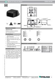
Abmessungen<br />
68<br />
38<br />
28<br />
M30 x 1.5<br />
ø 75<br />
ø 65<br />
ø 64.5<br />
144<br />
0.4 ... 0.5 Nm<br />
0.4 ... 0.5 Nm<br />
2.5 ... 3.75 Nm<br />
0.4 ... 0.5 Nm<br />
Dimensions<br />
Technische Daten Technical data<br />
-<br />
68<br />
38<br />
28<br />
M30 x 1.5<br />
Allgemeine Daten<br />
Erfassungsbereich 60 ... 550 mm<br />
Blindzone 0 ... 60 mm<br />
Normmessplatte 100 mm x 100 mm<br />
Wandlerfrequenz ca. 380 kHz<br />
Ansprechverzug<br />
Anzeigen/Bedienelemente<br />
> 10 s, Relais<br />
< 1 s, LEDs<br />
LED rot LED 1: Überfüllanzeige<br />
LED 4: Unterfüllanzeige<br />
LED grün/gelb LED 2: Überfüllwarnung bzw. Normalbetrieb <br />
LED 3: Normalbetrieb bzw. Unterfüllwarnung<br />
DIP-Schalter<br />
Elektrische Daten<br />
Einstellung der Schaltpunkte/Betriebsmodi<br />
Betriebsspannung UB 10 ... 253 V DC <br />
20 ... 253 V AC , 47 ... 63 Hz<br />
Leerlaufstrom<br />
Ausgang<br />
I0 < 30 mA bei UB = 30 V DC<br />
< 110 mA bei UB = 10 V DC<br />
< 25 mA bei UB = 220 V AC<br />
Ausgangstyp 3 Relaisausgänge, Schließer/Öffner wählbar<br />
Abstandshysterese H 20 mm<br />
Kontaktbelastung 253 V AC/150V DC, 3 A (ohm. Last)<br />
Lebensdauer elektrisch: 105 Schaltspiele bei ohm. Last<br />
(3 A/253 V AC bzw. 3 A/30 V DC)<br />
Mindestkontaktbelastung: 100 A/100 mV DC<br />
mechanisch: 20 x 10 6 Schaltspiele<br />
Temperatureinfluss<br />
Normenkonformität<br />
< 4 %<br />
Normen<br />
Umgebungsbedingungen<br />
EN 60947-5-2<br />
Umgebungstemperatur -20 ... 60 °C (253 ... 333 K)<br />
Lagertemperatur<br />
Mechanische Daten<br />
-40 ... 85 °C (233 ... 358 K)<br />
Schutzart IP65<br />
Anschluss Kabeldose 90° V7, (7-polig) <br />
Aderquerschnitt: 1,5 mm 2 Material<br />
<br />
Kabeldurchmesser Ø7 ... 9 mm<br />
Gehäuse Deckel: PC<br />
Gehäuse: PBT<br />
Gewindeflansch: Edelstahl<br />
Einbaustecker/Kabeldose: PETP<br />
Wandler Epoxidharz/Glashohlkugelgemisch; Schaum Polyurethan<br />
Masse 700 g<br />
Hinweis Im Falle des Verlusts oder der Beschädigung darf die Kabeldose ausschließlich durch eine identische<br />
Kabeldose des Typs V7-W von <strong>Pepperl+Fuchs</strong> ersetzt werden!<br />
<strong>Ultraschall</strong>-<strong>Sensor</strong><br />
<strong>Ultrasonic</strong> <strong>sensor</strong><br />
UC500-D1-3K-V7<br />
Elektrischer Anschluss Kurven/Zusätzliche Informationen Electrical connection Curves/additional information<br />
U<br />
A1<br />
A2<br />
A3<br />
1<br />
2<br />
3<br />
4<br />
5<br />
6<br />
UB<br />
UB<br />
Steckverbinder V7<br />
1 6<br />
5<br />
7<br />
2 3<br />
4<br />
Zubehör<br />
Kabeldose<br />
V7-W<br />
Charakteristische Ansprechkurve<br />
0,0<br />
0,1<br />
0,2<br />
0,3<br />
90 80 70 60 50 40 30<br />
0,4<br />
Abstand [m]<br />
0,5 0,6 0,7 0,8 0,9<br />
Kurve 1: ebene Platte 100 mm x 100 mm<br />
Kurve 2: Rundstab, Ø 25 mm<br />
2<br />
Winkel [Grad]<br />
1<br />
20<br />
-20<br />
10<br />
-0<br />
-10<br />
Anzeigen/Bedienelemente<br />
LED<br />
1 (rot)<br />
2 (grün/gelb)<br />
3 (grün/gelb)<br />
4 (rot)<br />
Einstellung<br />
Schaltausgänge<br />
Überfüllwarnung<br />
Normalbetrieb<br />
1 2 3 4 5<br />
S4 = OFF<br />
voll<br />
hoch<br />
normal<br />
leer<br />
ON<br />
ø 75<br />
ø 65<br />
ø 64.5<br />
S4 = ON<br />
voll<br />
normal<br />
niedrig<br />
leer<br />
Unterfüllwarnung<br />
TEACH-IN<br />
144<br />
0.4 ... 0.5 Nm<br />
0.4 ... 0.5 Nm<br />
2.5 ... 3.75 Nm<br />
0.4 ... 0.5 Nm<br />
General specifications<br />
Sensing range 60 ... 550 mm<br />
Unusable area 0 ... 60 mm<br />
Standard target plate 100 mm x 100 mm<br />
Transducer frequency approx. 380 kHz<br />
Response delay<br />
Indicators/operating means<br />
> 10 s, relay<br />
< 1 s, LEDs<br />
LED red LED 1: overfill indication<br />
LED 4: underfill indication<br />
LED green/yellow LED 2: overfill warning and normal operation <br />
LED 3: normal operation and underfill warning<br />
DIP-switch<br />
Electrical specifications<br />
setting of the switch points/operating modes<br />
Operating voltage UB 10 ... 253 V DC <br />
20 ... 253 V AC , 47 ... 63 Hz<br />
No-load supply current<br />
Output<br />
I0 < 30 mA with UB = 30 V DC<br />
< 110 mA at UB = 10 V DC<br />
< 25 mA at UB = 220 V AC<br />
Output type 3 relay outputs, normally open/closed, selectable<br />
Range hysteresis H 20 mm<br />
Contact loading 253 V AC/150V DC, 3 A (ohm. load)<br />
Lifetime electrical: 105 switching cycles with ohmic load<br />
(3 A/253 V AC or 3 A/30 V DC)<br />
minimum contact load: 100 A/100 mV DC<br />
mechanical: 20 x 106 switching cycles<br />
Temperature influence<br />
Standard conformity<br />
< 4 %<br />
Standards<br />
Ambient conditions<br />
EN 60947-5-2<br />
Ambient temperature -20 ... 60 °C (253 ... 333 K)<br />
Storage temperature<br />
Mechanical specifications<br />
-40 ... 85 °C (233 ... 358 K)<br />
Protection degree IP65<br />
Connection Cable connector 90° V7, (7-pin) <br />
Wire cross section: 1.5 mm 2 Material<br />
<br />
cable diameter Ø7 ... 9 mm<br />
Housing cover: PC <br />
housing: PBT<br />
threaded flange: stainless steel <br />
installation connector/cable socket: PETP<br />
Transducer epoxy resin/hollow glass sphere mixture; polyurethane foam<br />
Mass 700 g<br />
Note In case of loss or damage, the cable socket must be replaced by an identical cable socket (type V7-W) from <strong>Pepperl+Fuchs</strong>!<br />
U<br />
A1<br />
A2<br />
A3<br />
1<br />
2<br />
3<br />
4<br />
5<br />
6<br />
Connector V7<br />
1 6<br />
5<br />
7<br />
2 3<br />
4<br />
Accessories<br />
Cable socket<br />
V7-W<br />
UB<br />
UB<br />
Characteristic response curves<br />
0.0<br />
0.1<br />
0.2<br />
0.3<br />
Angle [degrees]<br />
90 80 70 60 50 40 30<br />
0.4<br />
Distance [m]<br />
0.5 0.6 0.7 0.8 0.9<br />
Curve 1: flat surface 100 mm x 100 mm<br />
Curve 2: round bar, Ø 25 mm<br />
2<br />
45-2887A<br />
212371<br />
Doc. No.:<br />
07/08/2009 DIN A3 -> DIN<br />
Part. No.:<br />
Date:<br />
1<br />
20<br />
-20<br />
10<br />
-0<br />
-10<br />
Indicators/operating means<br />
LED<br />
1 (red)<br />
2 (green/yellow)<br />
3 (green/yellow)<br />
4 (red)<br />
switch output<br />
adjustment<br />
overspill warning<br />
normal operation<br />
1 2 3 4 5<br />
S4 = OFF<br />
full<br />
high<br />
normal<br />
empty<br />
ON<br />
S4 = ON<br />
full<br />
normal<br />
low<br />
empty<br />
run-dry warning<br />
TEACH-IN mode
Hinweise Notes<br />
Sicherheitshinweise:<br />
Der Versorgungskreis ist vom Relaiskreis durch Basisisolierung getrennt.<br />
Der Deckel darf nur von unterwiesenem Fachpersonal geöffnet werden. Bei geöffnetem Deckel ist der<br />
Verschmutzungsgrad 2 zulässig. Der Dichtring am Deckel ist auf einwandfreien Zustand zu prüfen.<br />
Schutzklasse II ist nur bei Verwendung der vorgesehenen Kabeldose gewährleistet. Die Kabeldose darf<br />
nur in spannungslosem Zustand vom Gerät getrennt werden.<br />
Der Anschlussstift 7 des Gerätesteckers ist im <strong>Sensor</strong> nicht belegt. Ein eventuell vorhandener<br />
Erdungsanschluss in der Kabeldose wird somit nicht zum <strong>Sensor</strong> durchgeschleift.<br />
ACHTUNG:<br />
Der <strong>Ultraschall</strong>-<strong>Sensor</strong> UC500-D1-K3-V7 ist kein elektrisches Betriebsmittel für<br />
explosionsgefährdete Bereiche.<br />
Normenkonformität: EN 60947-5-2<br />
Isolation Gehäuse: Schutzklasse II<br />
Verschmutzungsgrad: 4 (Prozessseite)<br />
3 (Gehäuse- und Steckerseite)<br />
Überspannungskategorie: III<br />
Einlernen der Schaltpunkte:<br />
Für jeden der 3 Schaltausgänge kann ein Schaltpunkt eingelernt werden. Dazu muss der <strong>Sensor</strong> durch Schalten des DIP-Schalters 5 auf die<br />
Stellung ON in den Einlernmodus versetzt werden. Der <strong>Sensor</strong> zeigt den Einlernmodus durch zwei leuchtende rote LEDs an. Die grün-gelben<br />
LEDs sind aus.<br />
Anschließend muss ein geeignetes Zielobjekt im gewünschten Schaltabstand vor dem <strong>Sensor</strong> positioniert werden und der dem jeweiligen<br />
Schaltausgang zugeordnete DIP-Schalter (Schalter 1-3) umgelegt werden. Der <strong>Sensor</strong> blinkt jetzt (zusätzlich zu den rot leuchtenden LEDs)<br />
gelb oder grün. Grün blinkend bedeutet, dass der <strong>Sensor</strong> das Zielobjekt erkannt hat, gelb blinkend zeigt an, dass das Zielobjekt nicht erkannt<br />
wurde. Der gemessene Schaltabstand wird ins RAM übernommen, wenn der zugehörige DIP-Schalter bei grün blinkender LED<br />
zurückgeschaltet wird. Anschließend leuchten wieder nur beide roten LEDs. Dadurch wird dem Bediener angezeigt, dass die DIP-Schalter 1-<br />
3 wieder in ihrer ursprünglichen Position stehen. Die anderen Schaltpunkte werden auf die gleiche Weise festgelegt. Der Einlernvorgang wird<br />
abgeschlossen, indem der DIP-Schalter 5 wieder auf die Stellung OFF gestellt wird. Die gemessenen Schaltpunkte werden dann<br />
speicherresident ins EEPROM übernommen.<br />
Normalerweise sollte der Schaltpunkt A1 kleiner als der Schaltpunkt A2 und der Schaltpunkt A2 kleiner als der Schaltpunkt A3 sein. Wenn<br />
dies nicht beachtet wird, tauscht der <strong>Sensor</strong> nach dem Einlernvorgang selbsttätig die Schaltpunkte so aus, dass A1 < A2 < A3 gilt. Damit ist<br />
sichergestellt, dass sich die LEDs korrekt verhalten und der kleinste Schaltabstand Relais 1, der mittlere Schaltabstand Relais 2 und der<br />
größte Schaltabstand Relais 3 zugeordnet ist.<br />
Wenn während des Einlernens DIP-Schalter 4 gewechselt wird, dann wird anstatt eines Zielobjekts der dem Schaltpunkt zugeordnete<br />
Defaultwert eingelernt. Die Defaultwerte der Schaltpunkte betragen 60 mm für A1, 220 mm für A2 und 270 mm für A3.<br />
Anzeige während des Einlernens:<br />
DIP1-3 Ein/mehrere DIP-Schalter gewechselt<br />
Einlernen aktiv<br />
DIP4 Grundzustand<br />
Einlernen Objektabstand<br />
Zustand Objekt erkannt Objekt nicht<br />
erkannt<br />
gewechselt<br />
Defaultparameter<br />
Default aktiv<br />
im Grundzustand<br />
Einlernen abgeschlossen<br />
Grundzustand gewechselt<br />
LED 1, rot leuchtet leuchtet leuchtet leuchtet leuchtet<br />
LED 2, grün/<br />
gelb<br />
blinkt grün aus leuchtet grün aus leuchtet grün<br />
LED 3, grün/<br />
gelb<br />
aus blinkt gelb leuchtet gelb aus leuchtet gelb<br />
LED 4, rot leuchtet leuchtet leuchtet leuchtet leuchtet<br />
Während des Einlernens schalten die Relais in den „Sicheren Zustand“ (alle Relais schalten offen, unabhängig von Schließer/Öffner-Funktion).<br />
Einstellen des Schaltverhaltens:<br />
Im Normalbetrieb (DIP-Schalter 5 auf OFF) kann mit den DIP-Schaltern 1 bis 3 das Schaltverhalten der Schaltausgänge 1 bis 3 eingestellt<br />
werden. Steht der entsprechende DIP-Schalter auf ON, arbeitet der zugehörige Schaltausgang als Schließer, steht der DIP-Schalter auf OFF<br />
zeigt der zugehörige Schaltausgang Öffnerverhalten. Schließerverhalten bedeutet, dass das Relais anzieht, wenn der Objektabstand kleiner<br />
ist als der zugehörige Schaltabstand, Öffnerverhalten bedeutet, dass das Relais anzieht, wenn der Objektabstand größer als der<br />
entsprechende Schaltabstand ist.<br />
Bei Störung geht der <strong>Sensor</strong> in den sicheren Zustand (alle Relais schalten offen, unabhängig von Schließer-/Öffner-Funktion)<br />
Einstellen der Anzeigemodi:<br />
Mit DIP-Schalter 4 kann zwischen 2 Anzeigemodi gewählt werden:<br />
Anzeigemodus 1: DIP-Schalter 4 auf ON, Unterfüllwarnung:<br />
Objektabstand x x < A1 A1 < x < A2 A2 < x < A3 x > A3<br />
LED 1, rot (voll) blinkt aus aus aus<br />
LED 2, grün/gelb (normal) aus leuchtet grün aus aus<br />
LED 3, grün/gelb (niedrig) aus aus blinkt gelb aus<br />
LED 4, rot (leer) aus aus aus blinkt<br />
In diesem Modus dient LED 1 (rot) als Überfüllanzeige, LED 2 (grün) zeigt den Normalzustand an, LED 3 (gelb) dient als Vorwarnsignal, dass<br />
der Behälter fast leer ist und LED 4 (rot) signalisiert den Zustand „Behälter leer“.<br />
Anzeigemodus 2: DIP-Schalter 4 auf OFF, Überfüllwarnung:<br />
Objektabstand x x < A1 A1 < x < A2 A2 < x < A3 x > A3<br />
LED 1, rot (voll) blinkt aus aus aus<br />
LED 2, grün/gelb (hoch) aus blinkt gelb aus aus<br />
LED 3, grün/gelb (normal) aus aus leuchtet grün aus<br />
LED 4, rot (leer) aus aus aus blinkt<br />
In diesem Modus dient LED 1 (rot) als Überfüllanzeige, LED 2 (gelb) dient als Vorwarnsignal, dass der Behälter fast voll ist, LED 3 (grün)<br />
zeigt den Normalzustand an und LED 4 (rot) signalisiert den Zustand „Behälter leer“.<br />
Bei Störung geht der <strong>Sensor</strong> in den sicheren Zustand (alle Relais schalten offen, unabhängig von Schließer-/Öffner-Funktion).<br />
Adressen / Addresses / Adresses / Direcciónes / Indirizzi<br />
Contact <strong>Pepperl+Fuchs</strong> GmbH · 68301 Mannheim · Germany · Tel. +49 621 776-4411 · Fax +49 621 776-27-4411 · E-mail: fa-info@de.pepperl-fuchs.com<br />
Worldwide Headquarters: <strong>Pepperl+Fuchs</strong> GmbH · Mannheim · Germany · E-mail: info@de.pepperl-fuchs.com<br />
USA Headquarters: <strong>Pepperl+Fuchs</strong> Inc. · Twinsburg · USA · E-mail: fa-info@us.pepperl-fuchs.com<br />
Asia Pacific Headquarters: <strong>Pepperl+Fuchs</strong> Pte Ltd · Singapore · E-mail: fa-info@sg.pepperl-fuchs.com · Company Registration No. 199003130E<br />
For more contact-adresses refer to the catalogue or internet: http://www.pepperl-fuchs.com<br />
Safety notes:<br />
The supply circuit is separated from the relay circuit by basic insulation.<br />
The cover may only be opened by specially trained personnel. Pollution degree 2 is permissible when the<br />
cover is open. Ensure that the sealing ring of the cover is in good condition.<br />
<br />
Protection class II is only guaranteed when using the recommended cable box. The cable box may only be<br />
separated from the unit when the power is off.<br />
The connector pin 7 of the connector is not connected to the <strong>sensor</strong>. An eventually present earth connection<br />
in the cable socket therefore will not be looped into the <strong>sensor</strong>.<br />
CAUTION:<br />
The UC500-D1-K3-V7 ultrasonic <strong>sensor</strong> is not suitable for use in environments<br />
subject to explosion hazards.<br />
Conformity: EN 60947-5-2<br />
Housing insulation: Protection class II<br />
Pollution degree: 4 (process face)<br />
3 (housing- and connector side)<br />
Overvoltage category: III<br />
TEACH-IN of switching points:<br />
One switching point can be taught for each of the 3 switch outputs. Set DIP switch 5 to ON to put the <strong>sensor</strong> in TEACH-IN mode. The <strong>sensor</strong><br />
indicates TEACH-IN mode with two lit red LEDs. The green-yellow LEDs are off.<br />
Next, position a suitable target object at the desired switching point in front of the <strong>sensor</strong> and switch the DIP switch associated with the relevant<br />
switch output (switches 1-3). The <strong>sensor</strong> will now be flashing yellow or green in addition to the lit red LEDs. Flashing green indicates that the<br />
target object was detected; flashing yellow signals that it was not detected. The measured switching point will be transferred to RAM when the<br />
associated DIP switch is switched back while the LED is flashing green. Only the red LEDs should now be lit. This signals the user that the<br />
DIP switches 1-3 have been restored to their original positions. The other switching points are set in the same manner. The TEACH-IN<br />
procedure is completed by setting DIP switch 5 back to the OFF position. The measured switching points will then be transferred to the<br />
nonvolatile EEPROM.<br />
Under normal circumstances, switching point A1 should be less than A2, and A2 less than A3. If this is not observed, the <strong>sensor</strong> will<br />
automatically exchange the switching points after the TEACH-IN procedure is complete so that A1 < A2 < A3. This ensures that the LEDs<br />
respond correctly and that the shortest switching point is assigned to relay 1, the middle distance to relay 2 and the longest distance to relay 3.<br />
If DIP switch 4 is switched during TEACH-IN, the default value for the switching point will be set rather than a target object. The default values<br />
for the switching points are 60 mm for A1, 220 mm for A2 and 270 mm for A3.<br />
Display during TEACH-IN:<br />
DIP1-3 one or more DIP switches changed<br />
TEACH-IN active<br />
DIP4 normal state<br />
TEACH-IN of object distance<br />
changed<br />
default parameter<br />
State object detected object not detected default active<br />
in normal state<br />
TEACH-IN complete<br />
normal state changed<br />
LED 1, red lit lit lit lit lit<br />
LED 2, green/yellow flashes green off lit green off lit green<br />
LED 3, green/yellow off flashes yellow lit yellow off lit yellow<br />
LED 4, red lit lit lit lit lit<br />
The relays switch to the "safe state" (all relays open, regardless of close/open function) during TEACH-IN.<br />
Setting the switching behaviour:<br />
In normal mode (DIP switch 5 OFF), the DIP switches 1 to 3 can be used to set the switching behaviour of the switch outputs 1 to 3. If the<br />
associated DIP switch is ON, the associated switch output has a close function; if the switch is set to OFF the output has an open function.<br />
Close function means that the relay trips when the object distance is less than the associated switching point; in the case of open function, the<br />
relay trips when the object distance is greater than the switching point.<br />
The relays switch to the "safe state" (all relays open, regardless of close/open function) in the event of a failure<br />
Setting the display modes:<br />
Two display modes can be selected with DIP switch 4:<br />
Display mode 1: DIP switch 4 ON, underfill warning:<br />
Object distance x x < A1 A1 < x < A2 A2 < x < A3 x > A3<br />
LED 1, red (full) flashes off off off<br />
LED 2, green/yellow (normal) off lit green off off<br />
LED 3, green/yellow (low) off off flashes yellow off<br />
LED 4, red (empty) off off off flashes<br />
In this mode LED 1 (red) serves as the overfilling indicator, LED 2 (green) indicates the normal state, LED 3 (yellow) serves as the preliminary<br />
warning that the container is nearly empty and LED 4 (red) signalises the "container empty" state.<br />
Display mode 2: DIP switch 4 OFF, overfill warning<br />
Object distance x x < A1 A1 < x < A2 A2 < x < A3 x > A3<br />
LED 1, red (full) flashes off off off<br />
LED 2, green/yellow (high) off flashes yellow off off<br />
LED 3, green/yellow (normal) off off lit green off<br />
LED 4, red (empty) off off off flashes<br />
In this mode LED 1 (red) serves as the overfilling indicator, LED 2 (yellow) serves as the preliminary warning that the container is nearly full,<br />
LED 3 (green) indicates the normal state, and LED 4 (red) signalises the "container empty" state.<br />
The relays switch to the "safe state" (all relays open, regardless of close/open function) in the event of a failure.