You also want an ePaper? Increase the reach of your titles
YUMPU automatically turns print PDFs into web optimized ePapers that Google loves.
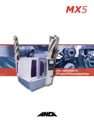
WATCHING THE WHEELS<br />
Zoller’s iCheck system delivers results<br />
BLANKET GRINDING<br />
with ANCA’s innovative TXcell<br />
SEvEN HoT TIpS<br />
for carbide tool production<br />
ANCA GERMANY<br />
celebrates 20 years<br />
ISSUE EIGHT <strong>2011</strong>
NaxoForce:<br />
Cutting Costs<br />
Switzerland<br />
Winterthur Schleiftechnik AG<br />
8411 Winterthur<br />
Phone: +41 (0)52 234 41 41<br />
Fax: +41 (0)52 232 51 01<br />
wst@winterthurtechnology.com<br />
Sweden<br />
SlipNaxos AB<br />
59383 Västervik<br />
Phone: +46 (0) 490 843 00<br />
Fax: +46 (0) 490 146 00<br />
support@winterthurtechnology.se<br />
United Kingdom<br />
Winterthur Technology UK Limited<br />
Sheffield S3 9QX<br />
Phone: +44 (0)114 275 4211<br />
Fax: +44 (0)114 275 4132<br />
info@winterthurtechnology.co.uk<br />
www.winterthurtechnology.com<br />
Germany<br />
WENDT GmbH<br />
40670 Meerbusch<br />
Phone: +49 (0) 2159 67 10<br />
Fax: +49 (0) 2159 80 62 4<br />
sales@winterthurtechnology.de<br />
Winterthur Technology GmbH<br />
72766 Reutlingen<br />
Phone: +49 (0) 7121 93 24 0<br />
Fax: +49 (0) 7121 93 24 24<br />
de.info@winterthurtechnology.com<br />
USA<br />
WENDT USA DUNNINGTON<br />
Royersford, PA 19468<br />
Phone: +1 (610) 495 2850<br />
Fax: +1 (610) 495 2865<br />
info@wdc.wendtgroup.com<br />
Winterthur Corporation<br />
Webster, MA 01570<br />
Phone: +1 (508) 949 1061<br />
Fax: +1 (508) 949 2086<br />
info@winterthurtechnology.us<br />
China<br />
Winterthur Technology (Taicang) Co., Ltd.<br />
215400 Taicang<br />
Phone: +86 512 8161 6800<br />
Fax: +86 512 8161 6822<br />
sales@winterthurtechnology.com.cn<br />
Australia<br />
Winterthur Technology Australia<br />
3198 Seaford<br />
Phone: +61 3 9773 5288<br />
Fax: +61 3 9773 5599<br />
guy@winterthurtechnology.com.au
02<br />
03<br />
04<br />
05<br />
06<br />
10<br />
16<br />
19<br />
20<br />
22<br />
24<br />
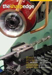
Cover Image: Gear-cutting hob resharpened on an ANCA TX7+ to Grade AAA.<br />
A market on the rise<br />
CEO Grant Anderson looks at the global grinding industry<br />
ANCA Germany - 20 years young<br />
Celebrating the 20th anniversary of ANCA GmbH<br />
ANCA gets GESAC seal of approval<br />
Xiamen Golden Egret tours ANCA factories<br />
Apprentice training centre launched<br />
New initiative at ANCA’s Melbourne plant<br />
Seven hot tips<br />
ANCA provides the good oil on carbide grinding<br />
Cool runnings<br />
Blaser Swisslube’s Rico Pollak on the impact of coolant<br />
TXcell and blanket grinding lead the way<br />
ANCA’s innovative new grinder increases productivity<br />
How to run a grinding test<br />
Winterthur’s Walter Graf with some sage advice<br />
CIM3D version 7<br />
A sneak peak at what you can expect from the new CIM3D<br />
Watching the wheel<br />
Zoller’s iCheck system saves time for Carbro Corp.<br />
Software tips<br />
How to get the most out of your iGrind suite<br />
The Sharp Edge is published by ANCA Pty Ltd. 25 Gatwick Road, Bayswater North, Victoria 3153, Australia. www.anca.com<br />
Executive Editor: Rob Chiarolli Editor: Steve Hitchen<br />
Contributions, Comments, Feedback: Got Some Comments? Ideas for articles? Please send your feedback and enquires to<br />
marketing@anca.com. All contributions are welcome<br />
Know someone who would like their own copy of The Sharp Edge. Please advise us and we’ll send them a copy.<br />
CoNTENTS - THE SHARP EDGE
After the challenging global financial crisis abated 18 months<br />
ago, the tool and cutter grinder market has shown significant<br />
improvement, giving ANCA plenty of reason to be optimistic<br />
about the future.<br />
We have been able to respond to the rapid growth in demand<br />
for our machines by ramping up production at our Bayswater,<br />
Australia and Rayong, Thailand plants. Our manufacturing<br />
output is now three times what it was in the first quarter of the<br />
2010 calendar year. There is no doubt that ANCA machines are<br />
more sought-after by our customers than ever before. Almost<br />
all global regions show improving trends in the order books,<br />
with Asia leading the way.<br />
New investment has added extra capacity to both plants<br />
and enabled us to expand our machine shop, necessitating<br />
an increase in labour across the company. We are now well<br />
positioned to take advantage of the growth in demand<br />
expected in the coming months, giving us the flexibility to<br />
respond quickly to customer requirements.<br />
ANCA Group Growth<br />
ANCA has been a truly global company for many years, but<br />
we continue to expand our reach into developing markets<br />
to ensure our customers get the best possible service in the<br />
quickest possible time. There have been a number of new<br />
facilities added to ANCA in the recent months.<br />
• A new office in Bangalore, India to improve our service to<br />
this important emerging market<br />
• A new engineering centre of ANCA subsidiary ANCA Motion<br />
in Melbourne, Australia<br />
• An expanded facility in Taiwan for ANCA Motion<br />
Manufacturing<br />
• A demonstration centre for ANCA Machine Tools in Taiwan<br />
2 ANCA - <strong>Issue</strong> 8 <strong>2011</strong><br />
A market<br />
on the rise<br />
each of these initiatives will provide ANCA with an increase<br />
in capacity and capability, and our customers can expect the<br />
benefits to flow on to them in the coming months.<br />
The Pursuit of Customer Satisfaction<br />
Our customer focus has developed further with the intent<br />
of providing complete satisfaction in everything we do. This<br />
includes product, quality, delivery and service, whilst adopting a<br />
streamlined approach to doing business.<br />
As part of this goal, we have refined our operations in the<br />
last year in the areas of marketing and product management,<br />
manufacturing management and engineering. We have also<br />
established a dedicated After sales and service division with a<br />
clear focus on service and training.<br />
And we won’t be stopping there. A number of exciting new<br />
projects are being developed and will be launched progressively<br />
in the next 18 months. each one of these is designed to further<br />
enhance our customers’ experience of dealing with ANCA.<br />
I would like to thank our global customers and suppliers for<br />
their business and support over the last 12 months. The strong<br />
relationships we have forged will continue to provide benefits<br />
for all of us well into the future.<br />
Grant Anderson<br />
Chief Executive Officer
ANCA Germany — 20 Years Young<br />
In 1991, ANCA made a critical decision to set<br />
up a new branch office in Germany, and this<br />
year celebrates the 20th anniversary of this<br />
major milestone in the company’s history. This<br />
is the story of ANCA GmbH..<br />
ANCA’s move into Germany in 1991 was not so much a first<br />
step, but rather an expansion; the company had had sales<br />
people on the ground for some time. However, with the release<br />
of the innovative TG7 machine, local tool manufacturers began<br />
to see the potential of the ANCA product, encouraging the<br />
company to commit themselves to a presence in Europe.<br />
ANCA Director and co-founder Pat Boland at the opening of ANCA GmbH in 1991. The<br />
branch has gone on to be one of ANCA’s most important offices.<br />
ANCA - <strong>Issue</strong> 8 <strong>2011</strong><br />
Directors Pat Boland and Pat McCluskey were faced with the<br />
truth that the epicentre of the world-wide grinding machine<br />
industry lay in the heart of europe, and particularly in Germany.<br />
For the Australian company to expand, they had to take on their<br />
competitors in their own backyard, and that was going to take<br />
hard work and determination. No-one has ever accused the<br />
Pats of lacking either of those.<br />
Twenty years later, ANCA GmbH is one of the company’s most<br />
important facilities, servicing a broad customer base right<br />
across the continent. Jan Langfelder, Managing Director ANCA<br />
GmbH was there at the beginning in 1991.<br />
“We actually incorporated the company in January 1991, but<br />
didn’t have the official opening until after eMO in June of that<br />
year. Our first location was part of a factory<br />
in Dusseldorf, where another Australian<br />
machine tool builder, LaserLab, used to reside.<br />
We had customers in Southern Germany<br />
and Switzerland. Mannheim seemed to be<br />
geographically suitable location to settle at.<br />
shortly after the company was incorporated,<br />
the economy faced crises and 1991-1992 were<br />
challenging years, not only for ANCA GmbH.<br />
Regardless, the company was committed to<br />
the European market and was not swayed by<br />
the tough start. It turned out to be a great<br />
decision.<br />
“Europe is the industry technology centre,”<br />
says Langfelder. “It was tough being from a<br />
company so far away, and from a country<br />
3<br />
ANCA NEWS
[Australia] without a strong association with engineering as<br />
such. The break-through came in 1993 when we released the<br />
MG7. With integrated automation and revolutionary software<br />
concept, we started to get some significant orders from major<br />
companies.”<br />
It was a lonely beginning for Langfelder, who was effectively<br />
the only person in the branch at the start, but he has plenty of<br />
friends now as the Mannheim facility houses over 20 staff and<br />
contains a spares store and demonstration centre. However,<br />
ANCA GmbH has outgrown its traditional home, and another<br />
expansion is planned.<br />
Jan Langfelder: “We are on the move again. In the near future<br />
we are planning a purpose-built facility that will cover almost<br />
2,000 m2. It will house a machine configuration and rebuild<br />
centre, the spares store and a state of the art demonstration<br />
centre to accommodate wide portfolio of our CNC grinding<br />
machines.<br />
“It is what we need to do to keep up with growth and make<br />
sure we continue to offer good service and spares delivery to<br />
customers in Europe. When you are on the doorstep of your<br />
major competitors you have make sure your customers are<br />
not disadvantaged by your headquarters being so far away [in<br />
Melbourne].”<br />
ANCA Gets GESAC<br />
Seal of Approval<br />
Chinese company Xiamen Golden Egret<br />
Special Alloy Co. Ltd (GESAC) is one of the<br />
largest-growing tool manufacturers in Asia,<br />
and one of ANCA’s most important partners.<br />
So far, GESAC has ordered 64 ANCA machines, with 43 already<br />
installed. As ANCA’s biggest customer in China, GESAC Director<br />
Mr Wu Gaochao and Vice General Manager Mr Li Lingxiang<br />
were invited to visit ANCA’s Thailand and Australia plants from<br />
24-29 April <strong>2011</strong>.<br />
Before visiting ANCA Thailand, GesAC senior management<br />
was concerned about the assembly quality and employees’<br />
skill level and discipline, in particular, when they learned that<br />
our factory is near the famous resort of Pattaya. However, to<br />
their surprise, they found a very clean, tidy, well organized and<br />
managed factory. Every item in factory was in good order and<br />
the machine fitters were working very efficiently.<br />
Mr Wu and Mr Li have visited a lot of machine tool factories in<br />
Germany, switzerland and usA and they commented that ANCA<br />
Thailand factory is one of the best among all machine tool<br />
factories visited.<br />
After Thailand, the GesAC people moved to the ANCA factory<br />
in Melbourne, inspecting the machine shop, assembly area and<br />
R&D grinding Centre.During the summary meeting of this trip<br />
with ANCA senior management, Mr Wu presented a special gift<br />
to ANCA director Pat McCluskey: a crystal award stating that<br />
4 ANCA - <strong>Issue</strong> 8 <strong>2011</strong><br />
ANCA GmbH has outgrown its Mannheim home and will soon be relocating to a<br />
purpose-built factory with expanded facilities.<br />
Building company-owned premises is a sign of commitment<br />
and confidence in the market. For ANCA, it also represents<br />
encouraging growth and confirmation that the decision to set<br />
up ANCA GmbH 20 years ago was a good call.s<br />
GESAC Director Mr Wu Gaochao presents the crystal award to ANCA<br />
director Pat McCluskey as ANCA CEO Grant Anderson, Regional Sales<br />
Manager james Tang and Branch Manager - Asia Jeff Foregard look on.<br />
ANCA is the best long-term strategic business partner of GESAC.<br />
Mr Wu commented that this partnership will be more and<br />
more important as GesAC cements its place in the cutting tools<br />
industry worldwide, with the aim of becoming the world top<br />
class tool manufacturer.<br />
Mr Wu and Mr Li said that ANCA had a lot of talented<br />
employees and great products, especially the control system<br />
and application software. Most important of all, Mr Wu stressed<br />
that customer orientation and quick action to solution is ANCA’s<br />
leading success factor, citing the new top clamp system as an<br />
example.<br />
GESAC believes ANCA will have a very bright future by<br />
overcoming some small quality issues. Inspired by results of<br />
this trip, Mr Wu suggested that they would come back to ANCA<br />
Melbourne and ANCA Thailand to celebration once they order<br />
place more machine orders on both factories.s
Apprentice<br />
Training Centre<br />
Launched<br />
A state-of-the-art Apprentice<br />
Training Centre has been launched<br />
at the ANCA manufacturing facility<br />
in Melbourne, Australia.<br />
ANCA is a world class innovative technology provider and has<br />
built a rich tradition of training apprentices and trainees over its<br />
37 year history.<br />
After many months of detailed preparation, an initiative of<br />
Pat McCluskey (Joint Managing Director) was launched after<br />
the assistance of many ANCA colleagues and some technical<br />
suppliers. ANCA has opened a new purpose-built Apprentice<br />
training Centre in an ANCA manufacturing facility in Melbourne,<br />
Australia. ANCA has dedicated a large area of previous<br />
production space to the Apprentice Training Centre.<br />
McCluskey, one of the two founders of ANCA, states that “it was<br />
important to me to pass on to others the excellent opportunity<br />
that I received when I underwent my apprenticeship many<br />
years ago. It really can lead as far as you want to take it. We<br />
deal with an exciting area of manufacturing industry at ANCA<br />
and I would like to share that with others. We will be teaching<br />
everything from mechatronics to fitting and turning. Another<br />
reason we launched the Apprentice Training Centre is because<br />
we couldn’t find training centres for trade level machine tool<br />
techniques. So we decided to establish one ourselves where we<br />
could train apprentices in-depth on how to build CNC machines<br />
and all associated skills”.<br />
Included in the brand new equipment sourced from everywhere<br />
from the uK to the us is a Festo Pneumatics training board<br />
and an ITu electrical Controls training panel. Apprentices will<br />
also undertake tasks such as building robot arms and learning<br />
to control them through their computers. Training will be a<br />
combination of ANCA-based training and one day per week at<br />
TAFE.<br />
ANCA will work closely with AiGTS (Australian Industry Group<br />
Training Services), who assists with the employment and<br />
administration of the apprentices, during the four year term<br />
of each apprenticeship. Five new apprentices started in May in<br />
addition to the placement of several apprentices in 2010. These<br />
apprentices will be the first apprentices to pass through the<br />
new training centre, and will help shape the training and skills<br />
development for future apprentices.<br />
The apprentices will spend their first 12 months in the training<br />
centre being taught the fundamentals of fitting and machining<br />
under the careful guidance of the Head of the Apprentice<br />
Training Centre, Roy Tomalin. They will be involved in building<br />
ANCA - <strong>Issue</strong> 8 <strong>2011</strong><br />
scale models of lathes, model robots, and building machines<br />
from the base to completion whilst they develop the important<br />
skills of scraping, grinding and machining before moving to the<br />
various areas in the workshop to further develop their skills.<br />
On the evening of Thursday 12th May ANCA launched the<br />
Apprentice Training Centre with AIGTs, parents, family and<br />
apprentices in attendance along with management and staff<br />
of ANCA. The evening was a huge success with parents noting<br />
what a “clean and modern” facility the ANCA factory is, and<br />
touched with the effort made to ensure their children were<br />
welcomed and were obviously entering a professional training<br />
and career choice. All parents and friends agreed that the<br />
apprentices are in for a fantastic four years of training and their<br />
careers in engineering will ensure they are highly skilled and<br />
sought after in their future endeavours.<br />
each apprentice was presented with an Indenture Certificate<br />
with official red embossed logo which was signed on the<br />
evening by the apprentice, guardian Pat McCluskey and the CeO<br />
Grant Anderson. This ceremony was undertaken to represent<br />
the Indenture ceremonies that represented the beginning<br />
of apprenticeships in the past and to communicate to the<br />
apprentices the importance of what they are undertaking.<br />
These indenture certificates will be held at the centre for<br />
presentation to each apprentice upon their completion of the<br />
apprenticeship.<br />
AiGTS employment consultant Craig Hilton made comment<br />
at the launch that “AiGTs are thrilled and appreciative of the<br />
efforts made by ANCA, and particularly the investment made by<br />
Pat McCluskey, to provide a facility such as this to allow young<br />
people to enter the trade of engineering and be able to learn in<br />
such a great environment”.<br />
ANCA and AiGTs look forward to training apprentices and<br />
to watching young people invest in their own futures by<br />
participating in an apprenticeship. ANCA also look forward to<br />
seeing these apprentices step into integral roles at ANCA in the<br />
future.s<br />
Top: Pat McCluskey (centre) shows new apprentices the finer points<br />
of CNC machine tool engineering.<br />
5<br />
ANCA NEWS
6 ANCA - <strong>Issue</strong> 8 <strong>2011</strong><br />
Seven<br />
Hot Tips<br />
Accelerate Carbide<br />
Tool Production<br />
Are you serious about carbide tool<br />
production? At ANCA, we certainly are! After<br />
24 years designing and building advanced CNC<br />
tool and cutter grinders, we’ve mastered a few<br />
tricks to get the most out of your tool grinder<br />
to produce high quality carbide cutting tools<br />
all day, everyday.<br />
Here’re our 7 hot tips to help you notch up<br />
your production rates and profitability.<br />
1.<br />
Wheels<br />
The wheel is the world’s greatest<br />
invention, make it work overtime<br />
for you<br />
To extract the most from your tool and cutter<br />
grinder for carbide tool production, it’s vital<br />
that you are using the right wheels, that they<br />
are perfectly balanced and qualified and that<br />
you keep them in top condition throughout a<br />
complete batch.<br />
So it all starts with wheel selection. Which wheels you select for<br />
each operation, can have a significant impact on tool quality,<br />
cycle time and the cost of your consumables. So choose your<br />
wheels carefully. Work closely with your wheel supplier to<br />
match wheel technologies to your application.
There are four basic criteria for selecting the perfect wheels for<br />
your application:<br />
• Wheel size and shape<br />
• Grit size<br />
• Grit material<br />
• Grit bonding method<br />
Your wheel’s size and shape will be largely determined by your<br />
application requirements and the physical constraints of your<br />
tool grinder and process.<br />
Choosing a grit size is relatively straight forward. use coarser<br />
grit size for heavier applications such as fluting; a medium grit<br />
size for more general grinding and roughing operations such<br />
as back off grinding, some point grinding, gashing and some<br />
profiling. Select a finer grit wheel for finish grinding, profiling<br />
and smaller tools.<br />
There are three grit materials commonly used in tool grinding.<br />
The hardest of these (Diamond) is the only grit type typically<br />
recommended for carbide grinding. The other common grit<br />
materials used in production grinding are Cubic Boron Nitride<br />
(CBN); which is often recommended for precision grinding of<br />
steels and Aluminium Oxide; which is softer than CBN but is<br />
easily dressed in process.<br />
The three most common grit bonding systems are resin bond,<br />
metal bond and vitrified bond. Each bond has its advantages<br />
and disadvantages. Resin bonds are most common and are also<br />
the most flexible. They can provide a good balance between<br />
form holding and wheel breakdown. Metal bonds tend to be<br />
much harder, making in-process dressing more difficult, and<br />
are best used in profiling operations as they provide the best<br />
wheel shape retention. Vitrified bonds can be a lot softer and<br />
can lose wheel shape much easier, though this type of bond is<br />
the easiest to dress both in and out of process. Recent grinding<br />
wheel technology has produced wheels with hybrid bonds.<br />
These wheels are best used for fluting as they provide much<br />
better wheel shape retention and thrive on deeper cuts with<br />
higher feedrates.<br />
Preparing the wheel for grinding is very important when<br />
manufacturing carbide tools. Most wheels should be dressed<br />
from new once mounted on your wheel arbor. Dressing the<br />
wheel on the arbor you intend to use is best practice. This<br />
ensures concentricity, helps with wheel balance and will be a<br />
contributing factor towards tool finish, wheel life and ultimately<br />
efficient carbide tool production.<br />
Once dressed, the wheel pack should be balanced. A balanced<br />
wheel pack avoids vibration and can contribute not only to<br />
improved tool finish, but also to extended wheel life, ultimately<br />
adding to your bottom line. Make sure you balance the wheel<br />
pack in the state it will be used on the machine. There are many<br />
methods which can be used to balance your wheel packs,<br />
however, the most accurate technique is to utilize balancing<br />
assist software built directly into some advanced tool grinders.<br />
This type of software detects vibration patterns in a spinning<br />
spindle and tells you exactly where to install your balancing<br />
weights.<br />
Conditioning your wheel (also commonly known as white<br />
sticking) clears out accumulated debris built-up between the<br />
grits. White sticking your wheel in-between tools helps to<br />
reduce the load on your wheel. You want to keep your wheel<br />
cutting your tool, not just heating it up. So white sticking helps<br />
ANCA - <strong>Issue</strong> 8 <strong>2011</strong><br />
your wheel stay efficient in-between dressing cycles. This<br />
means that you can run with a higher feedrate and really load<br />
up your wheel, knowing that it is cutting true to form. Keep<br />
an eye on your spindle load meter for several tools so you can<br />
get a feel of how often to white stick your wheel. If your tool<br />
grinder has an automatic white sticking option, make sure you<br />
schedule this into the process periodically to keep your wheel<br />
cutting strong.<br />
Depending on the type of wheel you have chosen, you may<br />
need to dress the wheel again during a batch if it dulls off too<br />
much or starts to lose shape. Advanced tool and cutter grinders<br />
often include in-process dressing abilities and you should<br />
schedule a dressing cycle after an appropriate number of tools<br />
if your wheel is of a dressable design. Ideally, your CNC tool<br />
grinder will automatically compensate for the slight change to<br />
the wheel diameter introduced by the dressing cycle.<br />
Your wheel supplier should be able to give you the correct<br />
wheel speed for your wheel in RPM or surface speed. Feed rates<br />
will vary between different tools and operations. Optimal feed<br />
rate is a balance between wheel wear, spindle load, tool rigidity,<br />
finish, accuracy and cycle time. Your wheel supplier should be<br />
able to give you a starting point but you can gain significant<br />
improvements in cycle time or accuracy by optimizing your<br />
feedrate to suit your specific application.<br />
So to sum up, the wheels you choose for your job, what speeds<br />
and feed you run and how well you setup and maintain your<br />
wheels before and during the job all have a huge impact on<br />
your ability to crank out quality tool after quality tool at a<br />
profitable rate. [901 words]<br />
7<br />
SEvEN HoT TIpS
2.<br />
Coolant<br />
Get your coolant clean and mean<br />
Your coolant has two primary jobs; lubrication and heat dissipation.<br />
The goal in coolant delivery is to inject the coolant as far as<br />
possible into the cut zone so that each wheel grit is lubricated<br />
throughout its entire contact run. This is not as easy as it looks<br />
though. You need to ensure your coolant system has sufficient<br />
pressure to obtain the required velocity needed for the particular<br />
operation at hand. At the same time, having the proper flow<br />
rate and temperature control will help dissipate heat away from<br />
the cut zone. Laminar (also called coherent-jet) nozzles can improve<br />
the effectiveness of both the pressure and flow that the<br />
coolant pump is supplying. Delivery of coolant into the cut zone<br />
as a laminar flow reduces the amount of turbulent air that is induced<br />
into the coolant stream. Air in the cut zone will decrease<br />
the cooling and lubricating efficiency of your coolant so it pays<br />
to get your flow as laminar as possible. Laminar nozzles are also<br />
more forgiving in terms of the distance your grind point can<br />
drift from the nozzle orifice allowing you more flexibility in your<br />
setup. If you also grind HSS, coolant delivery and flow to the cut<br />
zone are even more critical than for carbide grinding.<br />
To keep sufficient coolant flowing into the cut zone, make sure<br />
your coolant nozzles are mounted relative to each wheel pack,<br />
ensuring your coolant nozzles are directed at the cut zone<br />
whilst remembering that the cut zone relative to the wheel can<br />
alter during the course of an operation and can differ for each<br />
operation you perform on the tool.<br />
In some cases, you might find that directing one coolant jet<br />
tangential to the wheel, just in front of the cut zone “drags”<br />
coolant into the zone more effectively than directing the jet<br />
straight at the cut zone.<br />
Keeping these factors in mind can benefit the grinding process<br />
by<br />
• Reducing dressing frequency<br />
• Reducing wheel load<br />
8 ANCA - <strong>Issue</strong> 8 <strong>2011</strong><br />
• Producing less thermal damage to the work piece<br />
• Less coolant jet deflection caused by the vapor barrier<br />
surrounding the wheel<br />
An often overlooked factor is the cleanliness of your coolant.<br />
If your coolant gets contaminated, it adds friction to your<br />
process and you’ll find you need to slow your feedrate down,<br />
the surface finish of your tools will degrade and your wheels<br />
will wear quicker. Dirty coolant cannot efficiently carry grinding<br />
swarf away from the cut zone therefore causing the grinding<br />
wheel to load up sooner than expected.<br />
Micro sized tools are a good example where clean, temperature<br />
controlled coolant delivery are of the utmost importance.<br />
The high surface finish and tolerance requirements typically<br />
demanded in small tool manufacturing require the wheel<br />
to remain very free and sharp in its cutting action to avoid<br />
unwanted tool deflection. A good filtration system will help<br />
maintain your coolant in pristine condition.<br />
In short, you want to keep your coolant injected deep into the<br />
cut zone and whether your grinding process requires heavy<br />
stock removal or the fussiest surface finish, good coolant<br />
filtration is a major contributor to efficient carbide tool<br />
production so keep your coolant clean and mean.
3.<br />
Support<br />
Give your tools the support they<br />
need<br />
When it comes to work-holding for carbide tool production,<br />
you are often faced with the question of whether to include<br />
additional support for the tool or simply rely on the collet<br />
clamping mechanism to provide that support and grind the tool<br />
“free-ended”.<br />
It’s true that a tool support system like a pop-up steady or<br />
a tailstock can, in some cases increase the setup time for<br />
a job, but you need to trade that off against the potential<br />
improvements you can gain in cycle-time. Often thought of as<br />
an aid to tighter tolerances, the humble steady rest can also<br />
be used as a production rate amplifier. By supporting the tool,<br />
you can ramp up the feedrate without suffering tool deflection.<br />
And in the last few tools prior to an automated wheel dress,<br />
a steady rest can help maintain your tolerances and avoid<br />
breakages, even as the wheel starts to dull off.<br />
Since no one support system suits all applications,<br />
manufacturers of modern tool and cutter grinders usually<br />
provide a choice of tool support systems from manually<br />
adjusted steady rests, right through to fully automatic, self<br />
centering, multi-diameter, multi-point clamping supports<br />
and tailstocks on programmable axes that move in perfect<br />
synchronization with the grinding wheel to always provide<br />
support where it is needed most. In the case of an automatic<br />
tailstock, it is even possible with an advanced system, to<br />
program the force that the tailstock will exert on the center,<br />
ANCA - <strong>Issue</strong> 8 <strong>2011</strong><br />
“... perfect<br />
synchronization with<br />
the grinding wheel<br />
to always provide<br />
support where it is<br />
needed most.”<br />
allowing you back it off for some operations like cylindrical<br />
grinding.<br />
As we’ve mentioned, the main reason to support your tool<br />
is to reduce deflection of the tool during grinding. Reduced<br />
deflection will improve your tolerances, run-out and surface<br />
finish. These characteristics feed directly into a higher quality,<br />
longer lasting tool that you should be able to charge a higher<br />
price for. But also, don’t forget to crank up your feedrate once<br />
you start supporting your tools, particularly during fluting,<br />
normally the slowest cycle in the production process. The<br />
increased support will in many cases allow you to chew through<br />
more carbide per minute without sacrificing tool quality<br />
or wheel life, further increasing your efficiency and adding<br />
incremental gains to your profitability.<br />
Even though you might expect to wear out your grinding wheels<br />
faster using a tool support system due to your faster feedrates,<br />
supporting your tool can in some cases actually extend the life<br />
of your wheels. The vibration that can be induced by grinding<br />
an unsupported tool can lead to chipping and wear along the<br />
edge of the wheel which can dramatically shorten the useful<br />
life of your wheel. You can minimize this undesirable effect by<br />
utilizing good tool support.<br />
It also pays to utilize a tool support system because you can in<br />
some cases, reduce the overall length of your tools because<br />
with good tool support, you might need less shank length in the<br />
collet to clamp on which means a shorter blank for the same<br />
uted length, so you get valuable saving on your raw carbide<br />
costs.<br />
So give your tools the support they need, so you can crank up<br />
your profits by increasing your feedrates at the same time that<br />
you are improving the quality of your finished carbide tools.<br />
Continued on Page 12<br />
9<br />
SEvEN HoT TIpS
Blaser Swisslube AG Head of Grinding<br />
Technology Rico pollak shares some thoughts<br />
about grinding fluid in this interview with The<br />
Sharp Edge.<br />
What is the ideal grinding process?<br />
That is a difficult question: I don’t know whether the ideal<br />
grinding process is even possible. Grinding is a very complex<br />
procedure, and after over 25 years of grinding experience,<br />
I think the best process is the one that makes the best<br />
compromise.<br />
The ideal grinding process would remove the maximum amount<br />
of material without any damage by heat, pressure or vibrations,<br />
while complying with surface quality requirements and<br />
tolerances. And if it were truly ideal, it would do all this reliably<br />
over a reasonable time period without blunting or excessively<br />
wearing the grinding disk.<br />
Why is grinding such a complex procedure?<br />
Grinding abrades the material rather than cutting it off as in<br />
most machining processes. And there are various phases before<br />
10 ANCA - <strong>Issue</strong> 8 <strong>2011</strong><br />
Cool<br />
Runnings<br />
How Cutting Fluids Impact the<br />
Grinding Process<br />
Modern cutting fluids have to meet wide-ranging<br />
requirements: technological, ecological, worksafety<br />
and cost-effectiveness.<br />
material removal even starts: first of all only the surface is<br />
chafed, then comes the furrowing phase, followed by gouging,<br />
and finally the actual material removal phase. In all four of<br />
these phases the material is warmed up considerably, so it is<br />
not surprising that 90 % of the energy input is transformed into<br />
heat and only 10 % is used for actually removing material. The<br />
cutting fluid plays an important role here, not only for heat<br />
removal but also for enhancing efficiency in all phases.<br />
What must the cutting fluid do?<br />
Firstly, it must cool – the friction heat developed during grinding<br />
has to be removed in order to prevent grinding burn, microcracks<br />
in the workpiece, or destruction of the grinding grain.<br />
secondly, it must flush the chips out of the grinding zone – to<br />
uphold surface quality and a sharp cutting edge. Thirdly, it must<br />
provide optimal lubrication – to reduce friction and enable<br />
higher grinding speeds and material removal rates. And last<br />
but not least: it must not only be safe for humans and the<br />
environment, but also machine-compatible.<br />
What does optimal lubrication mean?<br />
The primary purpose of lubrication is to reduce friction.<br />
Lower friction reduces heat development and the associated<br />
risk of grinding burn and micro-cracks. However, lubrication<br />
negatively influences the continuous self-sharpening effect on<br />
the grindwheel – but on the other hand it reduces grindwheel<br />
wear thereby. I would therefore define optimal lubrication as<br />
the best compromise between minimum friction and maximum<br />
self-sharpening effect.<br />
How can users take account of this?<br />
While copious lubrication reduces heat development,<br />
it also hinders penetration of the grinding grain, so that<br />
greater pressure is required between the grindwheel and<br />
the workpiece. This can cause grindwheel distortion and<br />
eccentricity with vibrations, leading to chatter marks on<br />
the workpiece. All in all: the deeper the cut, the greater the<br />
lubrication.
How can users select the most suitable<br />
grinding fluid?<br />
Each grinding process must be viewed as a whole. Most<br />
crucially, the grindwheel specification must suit the workpiece<br />
material. Decisive is also the difference between light grinding<br />
(cylindrical and flat grinding with low feed rates) and deep<br />
grinding. Putting it simply, for light grinding I would recommend<br />
a fully synthetic grinding fluid or an emulsion with low oil<br />
content, and for deep grinding with high material removal rates<br />
I would recommend a grinding oil or an emulsion with high<br />
oil content. For grinding hard metals it is better to use a fluid<br />
that prevents cobalt release. As you can see, the most suitable<br />
product depends on the application in question.<br />
How do you take account of the<br />
latest technologies in your product<br />
development?<br />
New materials, innovations in grindwheel technology, and everincreasing<br />
machine performance, also pose new challenges<br />
in grinding fluid development. In high-performance grinding<br />
technology, for example, peripheral speeds of 120 m/s are<br />
quite normal today – more than 400 km/h! Ideally the grinding<br />
fluid should leave the nozzle at the same speed, which is only<br />
possible at high pressure. This places extreme demands not<br />
only on foaming behaviour, but also on the emulsion as a<br />
whole. And the increasingly stringent legal requirements must<br />
also be complied with.<br />
All these trends have to be taken into account in developing<br />
new grinding fluids. Our specialists in various disciplines –<br />
chemistry, tribology, analysis, machining and grinding, safety<br />
– play a dynamic role in our development process. Another<br />
important aspect in staying on the front line of development is<br />
our intensive contact with customers and partners, machinery<br />
and grindwheel manufacturers, as well as universities and<br />
technology institutes.<br />
How feasible would it be to entirely<br />
dispense with grinding fluids?<br />
Minimal lubrication technology can be used today for a number<br />
of machining applications, but not for grinding, because the<br />
chips are much too small for adequate heat removal. For this<br />
reason I am convinced that grinding fluid cannot be dispensed<br />
with.<br />
To what extent does grinding fluid<br />
influence productivity?<br />
Increasing productivity means finishing more workpieces in the<br />
same time, by increasing the feed rate. This is possible with the<br />
right grinding fluid, which can also influence grindwheel wear<br />
and sharpness. Other productivity factors are long grinding fluid<br />
life and good machine compatibility, thereby saving disposal<br />
outlay and minimizing standstill time. sophisticated additives<br />
can enhance these qualities. s
4. optimise<br />
Invest minutes in optimization to save hours<br />
in production<br />
There is an age old saying that’s goes “Do it once. Do it right”.<br />
This holds true for production grinding too. You can save<br />
valuable time and money by taking a few minutes to set up and<br />
tune your carbide tool grinding process. A modern CNC tool<br />
and cutter grinder will have the capability to be finely tuned to<br />
maximize the efficiency of your production runs.<br />
Optimization begins with good setup. We’ve already discussed<br />
the physical aspects of setting up your tool grinder for carbide<br />
tool production; the importance of good wheel selection,<br />
coolant quality and flow, and the benefits of tool support. But<br />
what about the setup of the programs that will run your batch?<br />
A huge time waster can be configuring the software of your<br />
CNC tool grinder to actually grind exactly what you want to<br />
produce. The software installed on the CNC of your modern tool<br />
grinder should have user friendly screens to guide you through<br />
the setup process. If you are grinding very complex or unusual<br />
tools, you might need to ensure your CNC is running high end or<br />
specialist software options that help you to easily configure the<br />
12 ANCA - <strong>Issue</strong> 8 <strong>2011</strong><br />
geometry of these tools or you could waste hours or even days,<br />
trying to setup a tool that the software was never designed to<br />
cater for.<br />
One very effective way to quickly prove out a new tool design<br />
that could save you a big chunk of non-production down-time<br />
on your machine is “Dry Run” mode. When you have entered<br />
all the data describing your tool and the grinding cycles you<br />
want to run, switch on your CNC’s “dry run” mode and give the<br />
cycle a quick run through to check that all the machine motion<br />
looks reasonable. Better yet, perform your dry run using your<br />
CNC’s MPG feed feature if it has one. This ingenious invention<br />
lets you prove out a complete tool program by simply winding<br />
the hand-wheel. This leaves you in complete control at all times<br />
and eliminates any surprises you might otherwise get if you<br />
accidentally put the decimal point in the wrong place for one of<br />
your parameters!<br />
Dry running your program is effective and can save you lots of<br />
time and scrap tools, but by far the best time saving you can get<br />
for program setup is to go “offline”. Invest in a PC loaded with<br />
an identical copy of your CNC’s software and preferably 3D<br />
simulation software for the grinding process. You can then<br />
setup your next tool while the machine is busy producing the<br />
current batch. 3D simulation has revolutionized the CNC tool<br />
grinding industry and if you don’t have it in your shop, you will<br />
be losing out big time to your competitors who are using it.<br />
With 3D simulation, you can see exactly how the tool will look<br />
like and verify and measure the actual geometry, then make<br />
as many design changes you like, all without interrupting your<br />
machine tool from its very important job of making money for<br />
you.<br />
As well as selecting efficient spindle speeds and feedrates, there<br />
are other simple things you can do to maximize your production<br />
rates; some as simple as flicking a switch. The first thing to<br />
do is to switch on adaptive feedrate control on your CNC if it<br />
supports this feature. Adaptive control will alter the feedrate<br />
depending on the spindle load so you can go faster over the<br />
shallow cuts and the CNC will automatically slow the feedrate<br />
down during deep cuts. This translates immediately into faster<br />
grind times and maximum use of your expensive machine.<br />
Before switching on adaptive control, you should check your<br />
wheel specs first. some wheels, such as hybrid bond diamond<br />
wheels, must be loaded up aggressively to keep them sharp.<br />
It also pays to experiment. By monitoring the spindle load<br />
meter, you will sometimes find that you can lower the spindle<br />
speed and increase the feedrate for an aggressive cycle time<br />
improvement.<br />
Remember, the bigger the batch or the more times you<br />
anticipate running the same batch, the more it pays to spend<br />
some time in optimizing your process. You can even get to the<br />
point of optimizing the distance of approach, retract and gap<br />
movements between cycles to reduce cycle times, although<br />
you will find that on current releases of modern tool and cutter<br />
grinder software, that the software is often smart enough to<br />
make these adjustments for you automatically so your machine<br />
spends more time cutting metal and less time unproductively<br />
grinding fresh air.<br />
Remember, each optimization you make can be automatically<br />
reapplied the next time you run the same batch so it’s definitely<br />
time well spent, and when setting up “Do it once. Do it right!”
5. SpC<br />
Deploy your anchor to avoid drift<br />
There’s nothing more frustrating and costly than an unmanned<br />
production batch gone wrong half way through. Your tool<br />
grinder should have a number of features to help you monitor<br />
and control your process from the first tool in the pallet to the<br />
very last.<br />
If you’ve optimized your process properly, machine and tool<br />
accuracy should be very stable throughout an entire batch.<br />
However, due to wheel wear and possibly machine accuracy<br />
changes due to temperature shifts, you might experience slight<br />
inaccuracies creeping into your process during the grinding of a<br />
batch, which, if unmonitored, might result in part of your batch<br />
being ground out of spec.<br />
statistical Process Control (sPC) is a statistical technique for<br />
monitoring and controlling a process to ensure it remains<br />
within desired boundaries. If your CNC includes in-built SPC<br />
software, then you can switch this on and it will use the touch<br />
probe to monitor small samples of tools, usually by measuring<br />
the OD size or flute depth and will then feed adjustments back<br />
to the CNC to ensure the process stays within spec for the<br />
whole batch. Your sPC software will also chart the progress<br />
of your batch and report on your capability index so you<br />
have immediate feedback on the quality of the tools you are<br />
producing.<br />
Although modern tool grinders are built to minimize the<br />
effects that changes in temperature can have on tool accuracy,<br />
today’s tight tolerance requirements mean that in some<br />
cases, you’ll need to make adjustments to the process as the<br />
ambient temperature of the process changes. If you have a<br />
6. Unattended operation<br />
Turn off the lights to save the planet<br />
ANCA - <strong>Issue</strong> 8 <strong>2011</strong><br />
coolant chiller and good ambient air conditioning, this effect<br />
will be minimal, but not everyone has the luxury of a tightly<br />
controlled thermal environment and some people run to such<br />
tight tolerances that even slight changes in temperature can<br />
adversely affect tool quality.<br />
This is where Coolant Temperature Variation (CTV)<br />
Compensation can help. If your tool grinder is equipped with<br />
CTV, then at periodic intervals during a large batch of tools,<br />
the machine can use the touch probe to reference a known<br />
surface, re-calibrating the machine axes on the fly. The sample<br />
frequency can be increased at the start of the batch while the<br />
machine temperature stabilizes. The compensation can be<br />
scheduled at any point in the operating sequence to ensure<br />
the compensation occurs as near as possible to the most<br />
critical grinding operation. CTV can help you achieve very tight<br />
tolerances throughout an entire production run.<br />
so make sure you utilize good process monitoring and control<br />
techniques and take full advantages of your tool grinder’s<br />
automatic measurement and compensation features.<br />
If you’ve followed the previous five tips, your tool and cutter grinder should now be purring away, churning out quality tool after<br />
quality tool. If you grind a tool with an extremely long cycle time or if you’ve got a suitable automatic tool loader on your machine,<br />
you can now ramp up your profits by ramping down your supervision of the machine. switch off the lights in your factory and let the<br />
machine do the work for you, confidently knowing that your machine is well tuned and optimized, with your process under constant<br />
surveillance and control.<br />
Many tool and cutter grinders now include automated wheel pack changers. If your tools require some heavy cutting or ultra-fine<br />
tolerances, particularly if you are not able to dress in cycle, it’s a good idea to include multiple sets of identical wheel packs so you<br />
can schedule wheel pack swaps mid batch to keep your production process accurate and efficient.<br />
In the unlikely event that something does go wrong during grinding, it is possible with some tool grinder CNCs, to have the machine<br />
automatically send you a message via sMs, email or instant messaging, telling you exactly what the problem is. even if no problem<br />
occurs, it can be useful to use the CNC’s messaging feature to let you know your pallet is full of perfectly ground carbide cutting<br />
tools, just waiting for you to unload and turn them into profit.<br />
13<br />
SEvEN HoT TIpS
7. Do it Again<br />
Rinse and repeat<br />
A modern tool grinder gives you incredible flexibility to quickly<br />
design, setup and grind a myriad of complex cutting tools, but<br />
never forget that a repeat order for a batch you’ve already<br />
optimised will be profit straight in your pocket. For your regular<br />
runs, try to keep a set of wheel packs just for that job and make<br />
sure you have a good filing system for your wheel and tool<br />
definition files. This will cut your setup and qualification time<br />
down dramatically and get you moving from batch to batch in<br />
no time at all.<br />
Now, all that’s left is to put your feet up and relax, or head to<br />
the golf course while your machine makes the money for you,<br />
grinding a complete batch of quality carbide cutting tools.<br />
Better yet, why not head back to the office, grab a coffee and<br />
fire up your 3D simulator to work on your next job while the<br />
machine’s busy spitting out carbide swarf.<br />
A 3D simulator is not only good for setting up your next job<br />
offline, but it’s also an invaluable package for new tool design,<br />
optimisation, diagnostics, costing and training. You can also use<br />
it for marketing; just email 3D models of completed tools to<br />
your potential customers to show them quickly what you are<br />
capable of producing.<br />
If you want to branch out into a new market, some tool and<br />
cutter grinder suppliers will let you load a new application<br />
software package onto your simulator for free. You can<br />
then explore the market, become familiar with the software<br />
and produce 3D models of tools to email to your potential<br />
customers for acceptance or simply publish them on your<br />
company’s web page to get your product out there.<br />
Then, when you have secured the order you can commit to<br />
purchase the software for your grinding machine and actually<br />
launch into production of real parts with a high degree of<br />
confidence.<br />
Your 3D simulator is more than a piece of software and can<br />
directly contribute to the efficiency of your carbide tool<br />
production. It’s like a swiss army knife for your grinding<br />
business, with equal parts; 3D simulation, design, optimisation,<br />
diagnostics, training and a marketing tool. use it to its full<br />
potential and watch your business soar! s<br />
14 ANCA - <strong>Issue</strong> 8 <strong>2011</strong><br />
“use it to its full<br />
potential and watch<br />
your business soar!”
Seven Hot Tips Summary<br />
so, when you’re setting up your next batch, remember these 7 hot tips to accelerate your carbide tool production:<br />
Tip 1: The wheel is the world’s greatest invention, make it work overtime for you<br />
� Choose the correct wheel shape and size<br />
� Choose the appropriate grit size for the job<br />
� Choose the appropriate grit bonding method for the job<br />
� Dress the wheel (if applicable) on its arbour<br />
� Balance the wheel<br />
� White stick your wheel regularly during production<br />
� use in-process dressing (if applicable)<br />
Tip 2: Get your coolant clean and mean<br />
� use a high pressure, high flow coolant system<br />
� Mount your coolant nozzles relative to your wheels<br />
� use laminar flow nozzles<br />
� Keep your coolant as clean as possible<br />
Tip 3: Give your tools the support they need<br />
� use automated tool support whenever possible<br />
� Try increasing your feedrates once your tool is supported<br />
� Reduce your clamping length to optimize your blank length<br />
Tip 4: Invest minutes in optimization to save hours in production<br />
� Make sure your software fully supports your tool types<br />
� Monitor spindle power to tune your spindle speed and feedrates<br />
� switch on adaptive feedrate control<br />
� Optimize your approach and retract moves<br />
� use “dry run” mode to prove out your new tool designs<br />
� use MPG feed to improve safety and efficiency of your dry runs<br />
� setup your next job offline on a PC running 3D simulator software<br />
Tip 5: Deploy your anchor to avoid drift<br />
� use statistical Process Control (sPC) software to monitor and control your process<br />
� use Coolant Temperature Variation (CTV) compensation to keep your machine<br />
perfectly calibrated<br />
Tip 6: Turn off the lights to save the planet<br />
� use an automatic tool loader<br />
� use an automatic wheel pack changer<br />
� Switch on process messaging to keep you up to date via SMS<br />
Tip 7: Rinse and repeat<br />
� Keep one or more sets of pre-qualified wheel packs for each regular job<br />
� Organize your part and wheel description files to make batch changeover as smooth<br />
as possible<br />
� use your 3D simulator to prospect for new business<br />
ANCA - <strong>Issue</strong> 8 <strong>2011</strong><br />
15<br />
SEvEN HoT TIpS
TXcell and blanket<br />
grinding lead the way<br />
Demands on grinding machines change rapidly in today’s<br />
dynamic market. Often, just when a dedicated line is beginning<br />
to generate realistic profits, the market shifts, creating the<br />
need to re-tool. And customers are now demanding an everincreasing<br />
range of tools, in smaller batches and of higher<br />
quality, whilst at the same time insisting on cost savings and<br />
quicker deliveries. Tool manufacturers have no choice but to<br />
become more agile and responsive to their customers’ demands<br />
if they want to remain competitive.<br />
Too often, tool manufacturers are frustrated in their attempts to<br />
respond by the lack of flexibility in their tool grinders, making it<br />
hard for them to meet customer requirements. This increased<br />
need for tool makers to become more agile and responsive<br />
was the prime motivation behind ANCA developing the TXcell<br />
concept and a new process known as blanket grinding.<br />
The process and the machine combine to create greater<br />
opportunity to run the grinder without human intervention,<br />
and that means a significant cost saving.<br />
16 ANCA - <strong>Issue</strong> 8 <strong>2011</strong><br />
The machine<br />
The TXcell mates two proven production superstars–the ANCA<br />
TX7+ and the Fanuc M20i/A robot–to create a grinding cell<br />
with new levels of potential in productivity, accuracy and costsavings.<br />
This is achieved by using the flexibility of the Fanuc<br />
robot to load tools, change wheel packs and perform ancillary<br />
operations that previously would have required extra machines.<br />
Now, for the first time, one machine is capable of making a<br />
complete tool from bar stock to finished part.<br />
At the heart of the TXcell is ANCA’s flexible software package,<br />
which has been the industry benchmark for easy-to-use<br />
software for over 30 years. As well as containing the iGrind<br />
suite, the software creates a seamless interface with the Fanuc<br />
robot that enables the two machines to operate as one coordinated<br />
grinding cell that is optimized to reduce cycle time<br />
and increase productivity across the batch.<br />
Further flexibility and economy comes through the machine
configuration, which starts with a simple nine<br />
wheel-station, two-pallet cell, and can be<br />
expanded up to 24-station, four-pallet option.<br />
Manufacturers can select the best TXcell variety<br />
to suit their business model without having to<br />
pay for capability they may never use. Regardless<br />
of the cell size, there are common benefits across<br />
the range.<br />
Operations that once required manual<br />
intervention are reduced or eliminated<br />
completely. With storage for up to 24 wheel<br />
packs, there is minimal need for the machine operators to<br />
handle the wheel packs. This reduces the pack-change time and<br />
increases safety because the operators don’t need physically<br />
place heavy wheel packs into the spindle themselves; the<br />
powerful Fanuc robot does all that for them.<br />
And with the ability to fit up to four wheels per pack, the<br />
cell will store and deploy a large number of wheels, meaning<br />
the right wheel is more likely to available for even the most<br />
innovative of tool design features. John Leppin II, of Garr Tool<br />
in Michigan, usA, recognized the capability of the TXcell almost<br />
immediately.<br />
“We face limitations with the number of machine operators we<br />
can get, so anything that can reduce machine down time is an<br />
advantage,” he observed. “With over 20 wheel packs available<br />
on the TXcell, we would look to have simplified wheel-pack<br />
configurations to avoid interference issues and simplify the setup.<br />
Then if we have repeat sets of those wheel packs, we can<br />
do batch runs of over 1000 tools in a single run.”<br />
One of the largest contributors to machine downtime can be<br />
the time taken to re-tool and tweak the set-up for a new batch.<br />
Even that has been accounted for in the design of the TXcell<br />
with tooling and scheduling software that will reduce the batch<br />
set-up downtime to almost zero.<br />
Blanket grinding<br />
As alluded to in the name, the ANCA-developed process of<br />
blanket grinding covers all the processes needed to go from bar<br />
stock to finished tool, with only one machine and one set-up.<br />
This eliminates the need for the separate sequential machines<br />
and processes that are traditionally needed to manufacture<br />
a complete tool. This makes the process far more efficient<br />
by reducing capital investment costs, factory floor space<br />
requirements, inventory stock and—most importantly—labour<br />
for manual handling and machine set-up.<br />
TXcell is flexible enough to include a variety of pre- and postgrinding<br />
operations directly into the cell. This satisfies the<br />
needs of customers like Duane Gliniecki of Sumitomo Electric<br />
ANCA - <strong>Issue</strong> 8 <strong>2011</strong> 17<br />
GRINDING TECHNoLoGY
Industries, Wisconsin, usA, who comments: “we are continually<br />
under pressure to combine processes. Bringing in a process like<br />
brush honing into this grinding cell is a great possibility”.<br />
Other ancillary processes such as laser etching of tools,<br />
deburring, or quality inspection can be integrated into the<br />
TXcell program. And since the robot handles these operations<br />
while the machine is busy grinding, that’s money saved, straight<br />
to the operator’s bottom line.<br />
Accessories<br />
ANCA’s TX7+ has matured over the years into an established<br />
market leader that lends itself well to customization. Labourand<br />
time-saving accessories such as Cimulator3D, in-process<br />
dressing, white sticking, P-axis steadies and iView camera all<br />
contribute to the target of lower cost and higher quality output.<br />
For tool manufacturers, this all translates to a competitive edge<br />
in the market place.<br />
Ancilliary operations such as camera inspections, seen here on a<br />
TX7+, are done on a TXcell whilst the grinding cycle is in process.<br />
18 ANCA - <strong>Issue</strong> 8 <strong>2011</strong><br />
Installing Cimulator3D on an independent PC further increased<br />
the productivity of the TXcell by enabling the operator to<br />
design and develop new tool shapes without having to use<br />
the tool grinder to experiment and test. This means the TXcell<br />
is available for production for longer periods of time, and<br />
expensive tool material is not wasted on unnecessary trials.<br />
The future<br />
Exactly what will it be? The only thing known for sure is that the<br />
future will not be the same as the present, and that successful<br />
tool manufacturers will need to be ready for whatever shape<br />
the industry will take. ANCA’s TXcell and the blanket grinding<br />
process are the first step in ensuring the operators can adapt<br />
quickly without having the capital expense of changing<br />
sequential production lines to match the new customer<br />
requirements. With that in their pockets, change will bring<br />
opportunity rather than restructure.s<br />
The Fanuc robot is programmed to change both the tool and the<br />
wheel pack, increasing productivity and lowering down-time.
HOW TO RuN A<br />
Grinding Test<br />
Often, the full potential of grinding wheels is not completely<br />
utilised. The recommended systematic approach is structured<br />
into six process steps: objective, preparation, run, evaluate,<br />
record and publish.<br />
Objective<br />
First, be clear what you or others want to achieve. Some<br />
objectives may be in conflict with each other:<br />
• Fixing an existing problem (burning, surface finish,<br />
dimensional stability)<br />
• Better process economy such as longer wheel life<br />
• High material removal rates, i.e. shorter cycle times<br />
• New specification to be tested<br />
• More reproducible results<br />
Preparation<br />
Make yourself familiar with the key issues and record them:<br />
• Material removal rate Q’ w or Q-prime<br />
• Wheel speed v c<br />
• Feed-rate vw • Total amount of grinding allowance and depth of cut ae<br />
and number of cuts<br />
• Dressing parameters such as speed ratio q s , infeed,<br />
synchronous or asynchronous dress<br />
Ask the operator about the main problems that may have been<br />
encountered:<br />
• Does or did the wheel lose form?<br />
• Did you experience burning or chatter?<br />
• Is the process stable?<br />
• How does the coolant supply behave? Is it the same over a<br />
full shift?<br />
• Is the fixturing rigid? Do vibrations occur?<br />
• Can you maintain dimensional stability?<br />
Run<br />
If the existing parameters for a given wheel are reasonable,<br />
repeat those parameters with a new wheel specification and<br />
compare results.<br />
To establish the feed-rate v , use the specific material rate Q’ w w<br />
Q = (a × v )<br />
w e w<br />
60<br />
• Creep-feed grinding hardened steel: 5 to 10 mm/mm/s<br />
• Creep-feed-grinding aerospace nickel alloys: 10 to 20 mm 3 /<br />
mm/s<br />
• Flute grinding of taps with resin bonded wheels: 10 to 20<br />
mm 3 /mm/s<br />
• Flute grinding solid carbide mills: 6 to 12 mm 3 /mm/s<br />
These values depend on the stiffness of the machine tool, the<br />
fixturing of the workpiece, etcetera.<br />
Evaluate<br />
Before making too many changes to any given process, run it<br />
for a while. Good engineering is to change only one parameter<br />
at a time, observe changes, evaluate and then make changes.<br />
Measure components for dimensional accuracy, burr formation<br />
and grinding abuse (burning). Loss of form, for example,<br />
indicates one or several of the following things:<br />
• The wheel is too soft<br />
• Surface speed is too low (increase by steps of 3 to 5 m/s)<br />
• Feed-rates are too high<br />
• Amount of dressing is insufficient<br />
• The grit size is too coarse<br />
EXPERT ADVICE<br />
Walter Graf of Winterthur Technology Group shares some expert advice on the tricky subject of<br />
running grinding tests.<br />
• Did the process result in burning?<br />
Check coolant delivery. Is nozzle in right position? The surface<br />
speed v may be too high; try to reduce it by 3 to 5 m/s. You<br />
c<br />
may increase the feed-rate to increase self-sharpening of wheel<br />
by using 10% steps.<br />
Record<br />
Create your own spread-sheet listing all the main parameters.<br />
publish<br />
Share your results with your colleagues and build a database<br />
that will give you faster results next time you have to run a<br />
similar test.s<br />
Watch for the full version of Walter’s article in an upcoming<br />
edition of ANCA’s E-newsletter The Sharp E.<br />
ANCA - <strong>Issue</strong> 8 <strong>2011</strong> 19<br />
GRINDING TECHNoLoGY
SNEAK pEAK<br />
What’s New in<br />
CIM3D<br />
version 7<br />
ANCA’s Cim3D was the world’s first high<br />
quality 3D tool simulation software system<br />
and it’s fair to say it revolutionised the<br />
industry. Version 7 of this industry benchmark<br />
package is now available with a range of new<br />
features to improve usability, enhance tool<br />
verification abilities, and better analyse the<br />
grinding process.<br />
Cim3D is Now Faster<br />
Version 7 is faster. Optimisation of the 3D calculation engine<br />
has resulted in more than a 30% average speed improvement in<br />
simulation time compared to V6. More dramatic performance<br />
enhancements can be achieved in some cases when using arc<br />
blank sections, which are now supported in version 7. Due to<br />
the reduction of material removed when using a pre-formed<br />
blank compared to a cylindrical blank, calculation time is<br />
reduced. For certain profile blanks, the time savings can<br />
be significant. This has two benefits. Not only can complex<br />
profile tools be simulated in less time, but also the detail of<br />
the simulation can be increased significantly compared to<br />
previous versions to provide a more accurate tool model for<br />
measurement and verification purposes. (The use of arc blank<br />
sections will be supported within the iGrind blank editor in<br />
Toolroom RN31.1-1 onwards.)<br />
20 ANCA - <strong>Issue</strong> 8 <strong>2011</strong><br />
2D overlays for Instant visual verification<br />
The ability to verify geometrical features has been significantly<br />
extended in Cim3D V7 by providing the ability to import DXF<br />
overlays (2D CAD outline curves) into the measurement view.<br />
This can be used to verify various geometrical features of a tool<br />
such as the tool OD or core profile as well as the flute crosssection<br />
geometry. The DXF overlay can be conveniently enabled<br />
or disabled as required, as well as positioned and then locked<br />
with the tool model. The accuracy of the core and cutting<br />
profile display in Cim3D has also been improved in V7 so that<br />
DXF overlays can be accurately compared to these simulated<br />
profiles.<br />
From October <strong>2011</strong>, ANCA’s next release of the Toolroom<br />
software suite will provide the added benefit of automatically<br />
generating and sending the theoretical tool and cross section<br />
profiles to Cim3D, saving you even more time in the verification<br />
process. This will be particularly useful for ball-nose, corner<br />
radius, stepped and profile tools.<br />
Quicker Setup of Tooling and Accessory Models<br />
Machine accessory configuration was potentially a<br />
cumbersome task in previous versions. The new machine<br />
configuration dialog simplifies the task of setting up<br />
machine accessories by providing one convenient interface<br />
to set-up standard machine tooling including tool-holding,<br />
support systems, and dresser configurations. Accurate 3D<br />
representation of the grinding process as well as the machine<br />
set-up allows processes to be optimised and aids in identifying<br />
potentially costly mechanical crashes.<br />
A potential collision point on a grinding machine is the tool<br />
holding. Simulating the grinding process using an accurate<br />
model of the tool holder ensures that any potential collision is<br />
detected offline and is often easily rectified rather than causing<br />
a potentially costly collision. For this reason, DXF files can<br />
now also be imported into Cim3D to model tool holding. Tool<br />
holders can typically accommodate various collet or jaw sizes.<br />
To cater for this, a set of DXF files can be imported with various<br />
collet or jaw sizes to create a tool holding set. Cim3D can then<br />
automatically select the model based on shank diameter.<br />
Apart from importing custom tool-holding geometry, the new<br />
machine configuration dialog features the ability to easily select<br />
Over a wide range of tools, Cim3D V7 is<br />
approximately 30% faster than V6. Support<br />
for arc sections in blanks has also been added<br />
which in most cases speeds up simulation<br />
times further. In the example pictured, the<br />
same tool simulated in in 52% of the time in V7<br />
compared to to V6 in a high detail detail mode. When<br />
the actual radius blank was used, simulation<br />
time was reduced by almost 80%.
from a library of standard tool-holding<br />
options. All tool-holding options in the<br />
library include all available collet sizes<br />
thereby enabling Cim3D to select the<br />
appropriate collet based on shank size.<br />
In total, the standard library consists<br />
of more than 350 collet and adapter<br />
combinations. This feature automates<br />
the selection of the tool-holding model<br />
which results in more reliable collision<br />
detection. This saves set-up time, avoids<br />
mechanical crashes, and enables the<br />
minimum tool protrude length to be<br />
determined for optimal tool stability and<br />
run-out.<br />
Ultra-accurate Cross Section<br />
Measurement in Any plane<br />
Verification of tool geometry often<br />
involves cross-sectional measurement<br />
of geometric features. The “sectioning<br />
plane” feature in Cim3D has historically<br />
been used to slice the tool to inspect<br />
cross-sectional features in any plane<br />
orientation. This feature has been<br />
significantly enhanced in V7 by replacing<br />
the approximate positioning technique<br />
using the mouse with a positioning<br />
dialog allowing precise positioning of<br />
the plane. In keeping with the format<br />
most often used in tool drawings, you<br />
position the plane by specifying a series<br />
of translation and rotation movements<br />
about the plane. This provides the ability<br />
to dissect the tool with surgical precision<br />
along any cross-section specified on a<br />
tool drawing. The cross-section can then<br />
be accurately measured using the 2D<br />
cross-section view. In addition, the steps<br />
taken to position the plane can be saved<br />
and loaded to repeat measurements on<br />
similar tools.<br />
In-Depth Cycle Time Estimation<br />
Analysis of cycle time within the<br />
simulation environment allows<br />
optimisation of grinding moves to<br />
achieve the goal of maximising machine<br />
productivity by producing more tools<br />
per hour. Toolroom RN31 introduced an<br />
auto-approach move enhancement that<br />
automatically optimises all approach<br />
moves between operations so that<br />
cycle time saving can be automatically<br />
achieved by simply using Toolroom RN31.<br />
However, gap minimisation and feedrate<br />
optimization is an important step to<br />
achieve an efficient grinding process.<br />
Cycle time estimation within Cim3D has<br />
been extended in V7 by breaking down<br />
total cycle time into contact time, air<br />
time, gap time and rapid-move time. This<br />
allows improved analysis of the grinding<br />
process and the ability to better evaluate<br />
the effect of feedrate and gap-distance<br />
changes.<br />
Quick Width and Angle<br />
Measurements<br />
Smaller scale software enhancements<br />
affecting common tasks are often the<br />
ones most appreciated by regular users.<br />
An example of such an enhancement<br />
in V7 is the simplification of measuring<br />
between two points in the measurement<br />
view. The measurement view now<br />
features a way to set a reference point.<br />
As the tool is moved in the measurement<br />
view, the distance and angle from the set<br />
reference point is displayed on-screen.<br />
This is useful to precisely measure many<br />
geometric features such as land widths,<br />
radii, web thicknesses, etc.<br />
New Machine and Tooling<br />
Models<br />
Other enhancements in Cim3D include<br />
updates of mechanical models. ANCA’s<br />
new MX7 machine is now fully supported<br />
in V7 as well as related accessories<br />
such as the new MX7 P-Axis. This will<br />
allow collision detection for customers<br />
with MX7 machines. The Arobotech<br />
pad length for the P-Axis is now also<br />
adjustable via the machine configuration<br />
dialog for both TX7 and MX7 machines<br />
as well as the addition of the microadjustable<br />
pop-up steady and shoes.<br />
Tailstock models have been added for the<br />
RX7 and TapX machines.<br />
The release of Cim3D V7 represents<br />
another milestone for this industryleading<br />
software package by providing<br />
a range of productivity enhancements.<br />
Continual improvement of our software<br />
products ensures that our customers<br />
benefit from the competitive advantage<br />
of using ANCA solutions. We encourage<br />
our customers to provide feedback<br />
and improvement suggestions for<br />
consideration into future products. All<br />
feedback is reviewed and can be emailed<br />
to marketing@anca.com.<br />
Contact your local ANCA representative<br />
today to order your copy of Cim3D V7.s<br />
ANCA - <strong>Issue</strong> 8 <strong>2011</strong> 21<br />
SoFTWARE
Watching<br />
the<br />
Wheels<br />
Making precision carbide cutters for the aerospace industry<br />
means that Carbro Corp., Lawndale, CA, must be very responsive<br />
to large and small orders with very high quality, long-life cutting tools—<br />
mills, reamers, routers, countersinks, and more.<br />
The 40-year-old, family-run firm has made<br />
its reputation on producing high quality<br />
tools used by companies like Boeing,<br />
Lockheed and Northrop to machine<br />
aluminum, stainless steel and honeycomb<br />
composite material. The shop runs more<br />
than 40 wheel packs across its 5 ANCA<br />
grinders, mounting whatever pack is<br />
needed by any of the machines to fill an<br />
order in the shortest possible time.<br />
In most shops, that might get confusing<br />
and would be time-consuming.<br />
For example, with grinding and dressing<br />
cycles, the diamond wheels used by an<br />
RX7 one month may not have precisely<br />
the same diameters, face angles, and<br />
radius weeks later when the GX7 is<br />
assigned to produce more of the same<br />
tool.<br />
The solution for Carbro is ANCA iCheck, a<br />
collaboration between ANCA and ZOLLeR<br />
that measures grinding wheels and wheel<br />
packs, stores the actual wheel data,<br />
and transfers the data to the grinding<br />
machines.<br />
The wheel dimensions are checked on<br />
the ZOLLER CNC measuring machine<br />
before use. If required, the wheels are<br />
dressed, and the wheel pack is checked<br />
again. That actual data is uploaded, ready<br />
to use to update tool programs in iGrind<br />
next time the tool is ordered. <strong>Anca</strong> iGrind<br />
takes these measurements and makes<br />
the necessary adjustments to produce<br />
22 ANCA - <strong>Issue</strong> 8 <strong>2011</strong><br />
the programmed tool. The combination<br />
of iGrind simulation software with the<br />
iCheck measuring machine lets Carbro<br />
work out part programs in full detail<br />
offline and ahead of time.<br />
The ANCA machines at Carbro are<br />
networked to the computer storing the<br />
actual data, so when a tool is ordered,<br />
the machine downloads the actual wheel<br />
data for the pack to be used. That way,<br />
the first tool out of the machine is very<br />
close to specifications, according to<br />
Anders Plano, general manager.<br />
“The iCheck has allowed us to reduce<br />
set-up time for each job up to 50%,”<br />
Anders said. “The precise and reliable<br />
measurement of the wheel packs off-line<br />
lets us respond much more quickly to the<br />
smaller order quantities we are seeing<br />
and to run on any of our ANCA’s any of<br />
our thousands of different part numbers.<br />
Customers get exactly what they need,<br />
when they need it.”s<br />
Carbro Corp’s Anders Plano: “The iCheck has allowed us to reduce<br />
set-up time for each job by 50%.”
ANCA - <strong>Issue</strong> 8 <strong>2011</strong><br />
23
SoFTWARE TIpS<br />
Make the Most of Your<br />
iGrind Suite<br />
ANCA is renowned the world over for the flexibility of our tool grinding<br />
software. Here we introduce you to some of our latest software features that<br />
help you grind exactly what you want.<br />
Fixed-point Ballnose<br />
Grinding<br />
RN31 introduces many enhancements to the ballnose OD and<br />
ball finish cycle such as the ability to grind an eccentric OD<br />
and a facet ball in one continuous move. Another important<br />
development is the introduction of a Fixed Grind Point option.<br />
This option performs the ballnose OD grinding move as a 5-axis<br />
move, however it ensures that the same point of the grinding<br />
wheel is used throughout the move. using the same grinding<br />
point on the wheel means that variations in the ball profile do<br />
not occur as a result of using different points about the toroid<br />
radius of the wheel. using the Fixed Point Grinding method,<br />
the wheel will wear in one spot only resulting in simpler<br />
compensations and a more stable grinding process.<br />
A screen shot of the iGrind RN31 software showing the<br />
fixed-point ballnose grinding feature.<br />
24 ANCA - <strong>Issue</strong> 8 <strong>2011</strong><br />
Complex parameters<br />
Toolroom version RN28.1 introduced the concept of complex<br />
parameters and later releases added this ability to additional<br />
parameters. A complex parameter is one that you can optionally<br />
vary along the length it is applied to, instead of being restricted<br />
to just a constant value. Parameters with this ability have a<br />
sigma (Σ) symbol next to their input field as shown below.<br />
Clicking on the Σ symbol displays a dialog box which allows<br />
complex specification of the parameter (similar to using ANCA’s<br />
Variable Helix Wizard). For example, instead of a constant<br />
primary OD land width, this can be specified as:<br />
• A changing width from EOT to shank<br />
• A constant width followed by a transition to a different<br />
width and then constant again<br />
• Arbitrarily as a spline function.<br />
The image below shows the primary land width specified as an<br />
oscillating spline function. The result can be seen on the tool.<br />
This ability is also available for some of the feedrate parameters<br />
in fluting cycles which can be useful when grinding complex<br />
tools.
ANCA’s iGrind suite is a powerful tool, and the more<br />
operators know about its capabilities they more they<br />
can get from their grinding machine.<br />
Comparing Tools in CIM3D<br />
Cim3D has the ability to compare two tools at the same time.<br />
The method to do this is:<br />
1. simulate a tool and then save it as a VRML file. I.e. FILe-<br />
>SAVE-> VRML File (.WRL)<br />
2. Make a change to the tool and simulate again.<br />
3. To compare the old and new tools go to FILE->OPEN and<br />
open the saved VRML file.<br />
The two models should be shown side by side in Cim3D. Double<br />
clicking on the VRML model will display a menu with an “edit<br />
position” option. This can be used to move the position of the<br />
model and can even be used to lay one model on top of the<br />
other to further check for differences. Turning on the Cutting<br />
edges option and changing colour mapping can also help in<br />
comparing differences in models.<br />
Shift a Complete Set of Files<br />
to Another Machine<br />
Creating bundle files in RN31 simplifies the process of<br />
transferring files from one machine or simulator to another.<br />
Bundle files include the iGrind TOM file, wheel packs, dressing<br />
files, and any other file associated with the current tool. The<br />
Create Bundle option can be found under the FILe menu in<br />
RN31 within iGrind. Once transferred to a machine, the files are<br />
easily installed by using the Install Bundle option (from the FILe<br />
menu). To minimize the size of bundle files when transferring<br />
them to other machines or simulators, deselect the option to<br />
include debug files.<br />
Monitor Your productivity<br />
Monitoring machine productivity and utilisation is the first step<br />
towards optimising production. small improvements to set-up<br />
and cycle times can equate to significant long term productivity<br />
gains, allowing your machine to produce more parts per hour.<br />
A simple way to monitor productivity is to use the Production<br />
Data utility. This handy utility can be found under uTIL (F11) on<br />
the ANCA sidebar menu. The Production Data utility provides an<br />
easy way to monitor setup and cycle times which can then be<br />
used to collect information regarding productivity versus batch<br />
sizes.<br />
ANCA - <strong>Issue</strong> 8 <strong>2011</strong> 25<br />
SoFTWARE
Typically, the Production Data utility<br />
would be zeroed upon commencing<br />
set-up for a particular job. The Total Time<br />
counter monitors the time since zeroing,<br />
whereas the Operating Time counter<br />
monitors the time the machine is incycle.<br />
From this information, a machine<br />
utilisation percentage is calculated as<br />
well as the number of tools produced per<br />
hour relative to total and operating time.<br />
Apart from information gathering and<br />
analysis, the utility can be used to set<br />
and monitor daily production goals.<br />
Monitor Your<br />
Spindle Load<br />
Analysing spindle load during grinding<br />
can be used to optimise and improve<br />
various aspects of the process. The<br />
Tool Grind Page (TGP) provides a visual<br />
gauge to view the current spindle load,<br />
however, in many cases it is useful to<br />
chart the history of the spindle load to<br />
see how it changes over time. This can be<br />
easily achieved using the Chart Recorder<br />
application. This utility can be accessed<br />
via the icon on the top right hand corner<br />
of the TGP.<br />
The Chart Recorder application provides<br />
a convenient way to visually monitor<br />
spindle load over time. The update speed<br />
as well as the scale of the graph can be<br />
adjusted and the results logged to a file<br />
for further analysis.<br />
Flute grinding provides a good example<br />
of where spindle load can provide<br />
important feedback regarding process<br />
setup. The figure below shows a fluting<br />
process for a four flute Hss tool with<br />
three passes per flute. In this example it<br />
can be seen in the image on the left that<br />
maximum spindle load is obtained in<br />
the second set of passes. This generally<br />
may not represent an ideal process. The<br />
image on the right shows an optimised<br />
26 ANCA - <strong>Issue</strong> 8 <strong>2011</strong><br />
Constantly monitoring your grinder’s productivity<br />
enables you to make small adjustments that can<br />
equate to more parts per hour.<br />
process with the desired decreasing load<br />
characteristics for this process.<br />
Apart from infeed adjustment, the Chart<br />
Recorder can show if spindle load is<br />
increasing over a batch of tools for a<br />
given tool grinding operation. This may<br />
provide important information regarding<br />
ideal wheel white-sticking or dressing<br />
intervals.<br />
Advanced Tip: The Chart Recorder<br />
monitors spindle load by default.<br />
However, changing the logged variable<br />
from XILF17 to XILF31 in the “configure”<br />
dialog will allow logging of spindle<br />
temperature for machines fitted with this<br />
option.<br />
Monitoring the spindle load during grinding can be used<br />
to optimise and improve the process. iGrind’s Tool Grind<br />
Page (TGP) provides a visual method of seeing how the<br />
load changes over time.
iGrind RN31 contains a simple method of scaling tools to<br />
create the same tool in a different diameter.<br />
Scale your Tools<br />
to Minimise<br />
programming<br />
Time<br />
Cutting tools are typically created as a<br />
series consisting of different diameters.<br />
Geometry between tool diameters in<br />
a given series is generally very similar,<br />
with smaller tools being a scaled-down<br />
version of larger tools.<br />
As of Toolroom RN31, iGrind features<br />
an option to automatically scale tools<br />
to different diameters. For example, a<br />
10mm tool file can be scaled down to<br />
an 8mm tool file very easily using the<br />
Scale Tool feature, found under the<br />
iGrind TOOL menu. Simply click on the<br />
menu option and enter in the new tool<br />
diameter. iGrind will then apply default<br />
behaviour to scale the tool as required.<br />
For custom scaling behaviour, an<br />
advanced feature exists under the<br />
utilities -> scripting -> Write scaled script<br />
from current Tool iGrind menu option.<br />
This option allows a script to be created<br />
where the scaling for each parameter can<br />
be defined in simple scripting language.<br />
Either simple linear scaling or more<br />
complicated behaviour can be specified.<br />
The created script can then later be<br />
executed to create any size diameter<br />
tool.<br />
Advanced Tip: The tool parameters<br />
scaled by the default scaling option<br />
under the Tools menu are specified in<br />
the p:/toolroom/tcg/tga/autoscale.txt<br />
file. This file can be copied to a directory<br />
named p:/toolroom/misc/tga and<br />
modified to customise the parameters<br />
which are scaled.<br />
Wheel Wear<br />
Compensation<br />
All grinding wheels wear during use. The<br />
effect of wheel wear on the finished tool<br />
can be negligible, but as batch and tool<br />
size increases, the effect of wheel wear<br />
can become significant.<br />
As of Toolroom release RN30, iGrind<br />
features an option to automatically<br />
adjust the grinding wheel by known<br />
wheel wear rates. The feature is accessed<br />
via the TOOL menu. By knowing the<br />
approximate wheel wear rate for a given<br />
process in terms of wear per number<br />
of tools, this can be specified for each<br />
wheel. This can be particularly useful to<br />
negate the effect of wheel wear when<br />
grinding large batches of tools.s<br />
The wheel wear compensation function in iGrind is accessed via<br />
the TOOL menu.<br />
ANCA - <strong>Issue</strong> 8 <strong>2011</strong> 27<br />
SoFTWARE
CNC Data<br />
ANCA 5DX, Core 2 Duo min., 1 GB RAM, 15” touch screen, DVD RW, usB connectivity<br />
28 ANCA - <strong>Issue</strong> 8 <strong>2011</strong><br />
technical<br />
specifications<br />
Mechanical Axes<br />
X-axis Y-axis Z-axis A-axis C-axis p-axis<br />
Position Feedback Resolution 0.0001 mm 0.0001 mm 0.0001 mm 0.0001 mm 0.0001 deg 0.0001 deg<br />
0.0000039” 0.0000039” 0.0000039” 0.0000039”<br />
Programming Resolution 0.001 mm 0.001 mm 0.001 mm 0.001 mm 0.001 deg 0.001 deg<br />
0.000039” 0.000039” 0.000039” 0.000039”<br />
Software Axes: (patented) B, V, u, W<br />
Workpiece: Diameter 300 mm (12”) max., length for OD and end-face grinding 400 mm (16”) max, weight 25 kg (55 lbs) max*<br />
Drive System: ANCA Digital (Sercos standard). Direct drive on linear and rotary axes<br />
Machine Data<br />
Grinding Spindle: ANCA direct drive 37 kW (49 HP) induction motor; 10, 000 RPM standard (15,000 RPM optional)<br />
Wheel Arbor: BigPlus BT 40 Taper<br />
Electrical Power: 25 kVA<br />
Probe System: Renishaw<br />
Base Material: ANCAcrete polymer concrete<br />
Colour: RAL 7035 / RAL 5014<br />
Cell Data<br />
Robot: Fanuc M20i/A<br />
Power: 3 kVA<br />
Wheel Changer: standard nine wheel packs expandable up to 24. up to four wheels per pack, 15s change time<br />
Wheel Diameter: up to 300 mm on selected wheel pack stations<br />
Tool Loading: standard two pallets, expandable up to four, tool dia. range 3-32 mm, max. tool length 325mm, 15s change time<br />
*Depending upon tool set-up<br />
Large Floor Plan Small Floor Plan<br />
Height: 2230 mm [87.8”]<br />
Weight: 10 000 kg [22 000 lbs]
ANCA global<br />
Asia Pacific<br />
ANCA Pty Ltd, Melbourne Australia +61 3 9751 8200<br />
ANCA Machine Tool (Shanghai) Co. Ltd Shanghai China +86 21 5868 2940<br />
ANCA India Bangalore India +91 80 4219 8107<br />
ANCA Japan Nagoya Japan +81 561 53 8543<br />
ANCA Thailand Ltd Rayong Thailand +66 3 895 9252<br />
ANCA Motion Taichung Taiwan +886 4 2336 4386<br />
Sahamit Machinery Bangkok Thailand +66 2 295 1000<br />
CKB Hiroshima Japan +81 82 227 3211<br />
Nagoya Japan +81 52 776 4832<br />
Osaka Japan +81 6 6442 3270<br />
Tokyo Japan +81 3 3498 2131<br />
Allied Chase Shanghai China +86 21 6284 2166<br />
Leeport (Holdings) Limited Hong Kong China +852 2427 7991<br />
SH International Seoul South Korea +82 3 1777 3130<br />
Europe<br />
ANCA GmbH Mannheim Germany +49 621 338 100<br />
ANCA Italia Vicenza Italy +39 0444 341 642<br />
ANCA (UK) Ltd Coventry United Kingdom +44 24 7644 7000<br />
Karel Redig – ANCA Edegem Belgium +32 3448 4165<br />
Christophe Chaumet – ANCA Meximeux France +33 675 186 395<br />
Slawek Antoszczyk – ANCA Wielkie Drogi Poland +48 668 150 552<br />
Springmann Austria GmbH Feldkirch Austria +43 5522 70960<br />
ALBA Precision sro Brno Czech Republic +420 548 214 098<br />
KR Trading Juelsminde Denmark +45 75 69 01 35<br />
Soumen Hiontakone OY Mikkeli Finland +358 40 5055 159<br />
Tek Team Ltd Yehud Israel +972 3 632 3576<br />
Ravema AS Oslo Norway +47 66 85 90 10<br />
MAVIS VS Impex srl Bucaresti Romania +40 311 046 636<br />
ZAO Rosmark Steel St. Petersburg Russia +7 812 336 2727<br />
ALBA Precision sro Banska Bystrica Slovakia +421 48 414 8627<br />
Grupo Delteco Eibar Spain +34 943 70 70 07<br />
Ravema AB Varnamo Sweden +46 370 488 00<br />
Springmann SA/AG Neuchatel Switzerland +41 32 791 1122<br />
Niederburen Switzerland +41 71 424 2600<br />
Tool Man SARL (French region) Veyrier-Geneve Switzerland +41 22 890 0405<br />
CNC İleri Teknoloji ve Tic. Ltd. Şti Istanbul Turkey +90 212 786 6200<br />
North America<br />
ANCA Inc. Wixom, MI USA +1 248 926 4466<br />
ALTA Enterprises Center Valley, PA USA +1 610 866 8866<br />
Beckman Precision Inc. Greer, SC USA +1 864 801 8181<br />
Earth Falcon Lauderdale-by-the-sea, FL USA +1 945 202 9090<br />
Grinding Solutions San Pedro Garza Mexico +81 1776 5851<br />
Innovative Machine Solutions Inc. Watertown, WI USA +1 414 333 1343<br />
Machine Tool Marketing Inc. Tulsa, OK USA +1 918 369 7065<br />
Machines & Methods Inc. Bellevue, WA USA +1 425 746 1656<br />
Beaverton, OR USA +1 503 617 1992<br />
Magnum Precision Machines, Inc. Albuquerque, NM USA +1 505 345 8389<br />
Metalworking Technologies Limited Arlington Heights, IL USA +1 847 818 5800<br />
Modern Tools Inc. Stoneham, MA USA +1 781 438 3211<br />
Productivity Inc. Minneapolis, MN USA +1 763 476 8600<br />
Cedar Rapids, IA USA +1 319 632 4288<br />
Omaha, NE USA +1 402 330 2323<br />
Shenk Machinery Menlo Park, CA USA +1 650 766 7264<br />
Smith Industrial Machine Sales Rochester, NY USA +1 585 738 8323<br />
Smith Machinery Salt Lake City, UT USA +1 801 263 6403<br />
SMS Machine Tools Rexdale, Ontario Canada +1 416 675 7300<br />
Tornquist Machinery City of Industry, CA USA +1 714 572 6830<br />
Phoenix, AZ USA +1 602 470 0334<br />
Triad Machine Tool Co. Wheat Ridge, CA USA +1 303 424 0268<br />
South America<br />
ANCA do Brasil São Paulo Brasil +55 15 3221 5512