Provac 880 - Berkel Sales & Service
Provac 880 - Berkel Sales & Service
Provac 880 - Berkel Sales & Service

Create successful ePaper yourself
Turn your PDF publications into a flip-book with our unique Google optimized e-Paper software.
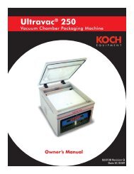
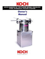
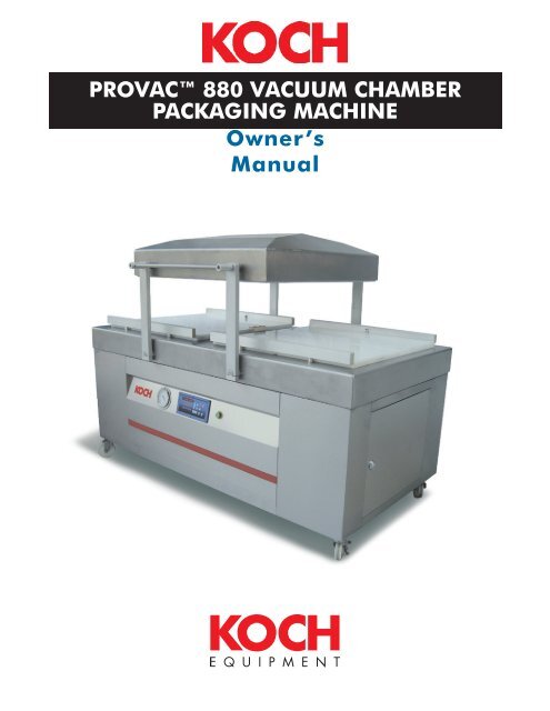
PROVAC <strong>880</strong> VACUUM CHAMBER<br />
PACKAGING MACHINE<br />
Owner’s<br />
Manual
KOCH EQUIPMENT LLC<br />
OWNER’S MANUAL<br />
905151<br />
H<br />
ProVac <strong>880</strong> Vacuum Chamber<br />
Packaging Machine
INTRODUCTION P A G E I<br />
TABLE OF CONTENTS<br />
INTRODUCTION ................................ III<br />
GENERAL ........................................... IV<br />
SECTION 1: SAFETY<br />
PERSONAL SAFETY .............................. 2<br />
FOOD SAFETY ..................................... 3<br />
GENERAL SAFETY GUIDELINES ........... 3<br />
SECTION 2: STARTUP<br />
UNPACKING ....................................... 6<br />
TRANSPORTATION INSTRUCTIONS ..... 6<br />
POWER REQUIREMENTS ...................... 6<br />
ENVIRONMENTAL REQUIREMENTS ..... 7<br />
STARTUP.............................................. 7<br />
VACUUM PUMP ROTATION ................. 7<br />
AIR CONNECTION .............................. 7<br />
GAS FLUSH OPTION ........................... 8<br />
PERFORATING KNIVES OPTION .......... 8<br />
SECTION 3: OPERATION<br />
PLACEMENT OF PRODUCT ................ 10<br />
STARTUP............................................ 10<br />
ENERGY SAVER .................................. 10<br />
DELAYED SHUT DOWN ......................11<br />
SEALING WITH AIR-ASSIST .................11<br />
GAS FLUSH OPTION ..........................11<br />
PERFORATING KNIFE .........................11<br />
CONTROL PANEL<br />
Operator’s Menu ............................... 12<br />
Panel Functions ................................. 12<br />
Edit Programs .................................... 13<br />
Error Messages ................................. 15<br />
SECTION 4: MAINTENANCE<br />
PRIOR TO CLEANING ........................ 18<br />
CLEANING RECOMMENDATIONS ..... 18<br />
VACUUM PUMP MAINTENANCE........ 19<br />
SEAL BAR MAINTENANCE ................. 19<br />
LID SPRING ADJUSTMENT ................. 20<br />
TROUBLESHOOTING<br />
Problems and Remedies ...................... 21<br />
SECTION 5: SCHEMATIC<br />
STANDARD UNIT.<br />
Designation and Function of Controls ... 23<br />
Electrical Diagram ............................. 24<br />
Electrical Diagram ............................. 25<br />
BIACTIVE SEALING UNIT<br />
Designation and Function of Controls ... 26<br />
Electrical Diagram ............................. 27<br />
Electrical Diagram ............................. 28<br />
PNEUMATIC DIAGRAM<br />
Designation and Function of Controls ... 29<br />
Diagram ........................................... 30<br />
SECTION 6: PARTS<br />
RECOMMENDED SPARE PARTS .......... 34<br />
CHAMBER LID<br />
Parts List ........................................... 35<br />
Diagram ........................................... 36<br />
SEAL BAR - 10MM<br />
Parts List ........................................... 37<br />
Diagram ........................................... 38<br />
SEAL BAR - CUT-OFF<br />
Parts List ........................................... 41<br />
Diagram ........................................... 42<br />
SEAL BAR - PERF KNIFE (OPTIONAL)<br />
Parts List ........................................... 43<br />
Diagram ........................................... 44<br />
WORKING BED, TOP<br />
Parts List ........................................... 45<br />
Diagram ........................................... 46<br />
CUSHION BAR - STANDARD<br />
Parts List and Diagram ........................ 47<br />
CUSHION BAR - GAS (OPTIONAL)<br />
Parts List and Diagram ........................ 48
INTRODUCTION P A G E II<br />
TABLE OF CONTENTS<br />
CUSHION BAR - BIACTIVE SEAL<br />
(OPTIONAL)<br />
Parts List ........................................... 48<br />
Diagram ........................................... 49<br />
CUSHION BAR - BIACTIVE SEAL W/GAS<br />
(OPTIONAL)<br />
Parts List ........................................... 50<br />
Diagram ........................................... 51<br />
CUSHION BAR - PERF KNIFE (OPTIONAL)<br />
Parts List ........................................... 52<br />
Diagram ........................................... 53<br />
CUSHION BAR - PERF KNIFE W/GAS<br />
(OPTIONAL)<br />
Parts List ........................................... 54<br />
Diagram ........................................... 55<br />
WORKING BED, BOTTOM<br />
Parts List ........................................... 56<br />
Diagram ........................................... 57<br />
BODY<br />
Parts List ........................................... 62<br />
Diagram ........................................... 63<br />
ELECTRICAL BOX - STANDARD<br />
Parts list ........................................... 64<br />
Diagram ........................................... 65<br />
ELECTRICAL BOX - AUTO LID SWING<br />
(OPTIONAL)<br />
Parts list ........................................... 66<br />
Diagram ........................................... 67<br />
ELECTRICAL BOX - BIACTIVE SEAL<br />
(OPTIONAL)<br />
Parts list ........................................... 68<br />
Diagram ........................................... 69<br />
ELECTRICAL BOX - BIACTIVE W/AUTO LID<br />
(OPTIONAL)<br />
Parts list ........................................... 70<br />
Diagram ........................................... 71<br />
SECTION 7: SERVICE HISTORY<br />
SERVICE HISTORY .............................. 74<br />
SECTION 8: VACUUM PUMP<br />
VACUUM PUMP MANUAL .................. 78
INTRODUCTION P A G E IV<br />
General<br />
This owner’s manual contains information pertinent to your ProVac<strong>880</strong>. Basic instructions<br />
and maintenance information is provided. Please read carefully. Failure to do so could result<br />
in bodily injury and/or damage to the equipment.<br />
Receiving Problems: As in all cases, before signing the bill of lading, be sure all items<br />
have been received as listed and there is no damage in shipment. If needed, a claim must<br />
be made immediately to the local truck line office and noted on the bill of lading.<br />
Please fill in the information from the bill of lading and the product identification tag.<br />
Model No.<br />
Serial No.<br />
Ship Date:<br />
Owner:<br />
Location:<br />
Electrical service size for you ProVac<strong>880</strong> (check one):<br />
208/240 Volt, 3 phase, 60 Hertz<br />
380/415 Volt, 3 phase, 50 Hertz<br />
460 Volt, 3 phase, 60 Hertz<br />
575 Volt, 3 phase, 50/60 Hertz<br />
Options installed on your ProVac<strong>880</strong> (check all that apply):<br />
Biactive Sealing<br />
Gas Flush<br />
Perforating Knife System<br />
Please fill in the serial number from the pump identification tag:<br />
Serial No.
INTRODUCTION P A G E V<br />
Specifications<br />
C<br />
F<br />
D<br />
G<br />
A B<br />
Length (A): 2040mm (80.3-in.)<br />
Width (B): 1300mm (51.2-in.)<br />
Minimum Height (C): 1220mm (48-in.)<br />
Working Height (D): 920mm (32.2-in.)<br />
Seal Bar Length (E): <strong>880</strong>mm (34.6-in.)<br />
Chamber Height (F): 254mm (10-in.)<br />
304mm (12-in.)<br />
Between Seal Bars (G): 860mm (34-in.)<br />
200m<br />
Vacuum Pumps:<br />
3 /h (117cfm) 5.6kW (7-1/2hp)<br />
306m3 /h (180cfm) 7.5kW (10hp)<br />
360m3 /h (212cfm) 9.0kW (12hp)<br />
Electrical Connection: See Power Requirements in Section 2<br />
Capacity: 15-35 seconds per cycle<br />
Net Weight: 780kg (1733-lbs)
INTRODUCTION P A G E VI<br />
This page left blank intentionally.
SAFETY P A G E 1<br />
SAFETY<br />
Personal Safety ................................................................................2<br />
Food Safety ......................................................................................3<br />
General Safety Guidelines ............................................................3<br />
SECTION<br />
1
SAFETY P A G E 2<br />
Personal Safety<br />
The procedures and guidelines herein must be followed precisely to avoid problems that can<br />
result in property damage, personal injury, or death. If you have any questions related to<br />
this information, please contact Koch Equipment <strong>Service</strong>s Inc. at (800) 777-5624.<br />
DANGER Hazardous voltage.<br />
Disconnect and lockout power before servicing machine or cleaning. Do not remove panels<br />
unless power has been disconnected and locked out at risk of electric shock hazard.<br />
WARNING<br />
Read and understand owner’s manual before using this machine. Failure to follow operating<br />
instructions could result in personal injury or damage to equipment.<br />
WARNING Explosion hazard.<br />
Do not use a gas with an oxygen content greater than 22% with gas flush option.<br />
CAUTION Blade hazard.<br />
Do not remove, install, or replace blades without protective gloves. Perforating blade is<br />
sharp. Use care when handling.<br />
Cleaning agents.<br />
Do not get the cleaning agents in eyes, on skin, or on clothing. Always wear rubber gloves,<br />
goggles, and protective clothing when contact is likely. Consult product manufacturer for<br />
specific details.<br />
Signal words used in classification of potential hazards are defined as follows:<br />
DANGER: Indicates an imminently hazardous situation, which, if not avoided, may result in death or<br />
serious injury.<br />
WARNING: Indicates a potentially hazardous situation, which, if not avoided, could result in death or<br />
serious injury.<br />
CAUTION: Indicates a potentially hazardous situation, which, if not avoided, may result in minor or<br />
moderate injury. Caution also indicates actions that may cause property damage.
SAFETY P A G E 3<br />
Food Safety<br />
Food Packaging<br />
While this machine is often used for food packaging and vacuum cooking, there are<br />
inherent risks associated with this packaging technique that could cause serious illness<br />
or death to the consumer of the food product. If you are using this machine for a food<br />
application, you must consult with a reputable food technologist or specialist in vacuum/<br />
modified atmosphere packaging (M.A.P.) to review the safety of your application.<br />
Gas Flush<br />
In order to ensure proper shelf life of the food product packaged in this machine, you<br />
must contact a reputable food technologist or specialist in vacuum/modified atmosphere<br />
packaging (M.A.P.) to review and develop the appropriate gas mixture for your package,<br />
and you must perform quality control and gas analysis on your finished M.A.P. packages.<br />
General Safety Guidelines<br />
Obvious safety guidelines should be observed.<br />
Use a certified electrician to install permanent electrical connection for your packaging<br />
machine. Failure to do so may result in death or serious injury and/or permanent<br />
damage to the machine.<br />
Disconnect and lockout power to your packaging machine before any maintenance work<br />
is performed.<br />
Place machine on a flat, stable surface.<br />
Do not place tools, parts, or other objects on or inside machine while operating.
SAFETY P A G E 4<br />
This page left blank intentionally.
STARTUP P A G E 5<br />
STARTUP<br />
Unpacking ........................................................................................6<br />
Transportation Instructions ............................................................6<br />
Power Requirements .......................................................................6<br />
Environmental Requirements ........................................................7<br />
Startup ..............................................................................................7<br />
Vacuum Pump Rotation ..................................................................7<br />
Air Connection ................................................................................7<br />
Gas Flush Option ............................................................................8<br />
Perforating Knives Option .............................................................8<br />
SECTION<br />
2
STARTUP P A G E 6<br />
Unpacking<br />
1. Carefully remove crate from the skid.<br />
2. Remove machine from skid.<br />
3. Wipe down outside of the machine.<br />
Transportation Instructions<br />
Precautions to take:<br />
Lift the machine by its center of gravity; this is not necessarily the same as the center of<br />
the machine.<br />
On lifting the machine with the forklift, do so from the front part (that opposite the<br />
electrical box). Check for components hanging under the machine.<br />
Always lift the machine by placing the forks of the truck between the two free casters of<br />
the machine; never lift it by the ends or extensions.<br />
Always take the utmost care when carrying out lifting and moving operations.<br />
Approximate weight of the machine: 780-kg or 1733-lbs.<br />
Power Requirements<br />
The owner must supply the correct 3 phase power source in accordance with the National<br />
Electric Code. The table below is based on the National Electric Code and is to be used as a<br />
guide in wire size selection and short circuit protection. The requirements noted in the table<br />
may change. Use a certified electrician to install permanent electrical connection for your<br />
packaging machine. Failure to do so may result in death or serious injury and/or permanent<br />
damage to the machine.
STARTUP P A G E 7<br />
Environmental Requirements<br />
Certain environmental factors affect the operation and lifespan of your vacuum packaging<br />
machine. The following requirements need to be adhered to when placing the machine:<br />
Room temperature from 5˚ to 40˚C.<br />
Machine must be at least 8-in. from walls or any other obstruction that would prevent air<br />
flow to the vacuum pump.<br />
Startup<br />
It is essential to check the oil level daily and to change the oil after every 500 hours of<br />
operation. Read the oil level with the machine turned off. Oil should be added until the<br />
level reaches the MAX level. Monitor the oil change indicator light on the control panel<br />
which signals an oil change is due. Refer to the pump manual, supplied (see Section 8), for<br />
details on changing the oil.<br />
OIL SIGHT<br />
MAX<br />
GLASS<br />
ON PUMP<br />
MIN<br />
Vacuum Pump<br />
NOTE: ALL CHAMBER MACHINES ARE SHIPPED WITH OIL IN THE PUMP. ALTHOUGH THE<br />
FACTORY RECOMMENDS CHECKING THE OIL LEVEL PRIOR TO FIRST USE!<br />
Vacuum Pump Rotation<br />
Cation: Check oil level of pump before starting pump. To check the direction of the pump<br />
rotation, briefly engage the “POWER ON” switch and observe the motor fan at the end<br />
of the pump. The fan should rotate as indicated by the arrow on the fan cover. To correct<br />
the rotation, switch any two phases in the plug. Ground wire must remain in the ground<br />
location.<br />
Air Connection<br />
The machine is equipped with a 1/4-in. hose barb for regulated air. The recommended air<br />
supply is 90 p.s.i. (6.2 bar) at 6 c.f.m. (10m 3 /h). There are three air regulators inside and in<br />
the rear of the machine. The maximum setting is 30 p.s.i. (2 bar) for the air-assist regulator.<br />
The Up Lid and Down Lid regulators are preset at the factory and should not be adjusted<br />
without consulting the Koch Equipment <strong>Service</strong>s Inc.
STARTUP P A G E 8<br />
Gas Flush Option<br />
The owner must supply a suitable regulator with a range of 0 to 60 p.s.i. A food-grade<br />
flexible hose with a 1/4-in. I.D. and a maximum length of 15-ft. Maximum regulator<br />
pressure is 55 p.s.i. is recommended.<br />
Perforating Knives Option<br />
CAUTION Blade hazard.<br />
Do not remove, install, or replace blades without protective gloves. Perforating blade is<br />
sharp. Use care when handling.<br />
Remove standard seal bars. Install perforating bars with the cutting blade facing toward<br />
the outside of the lid. The use of air-assist is required for proper operation. The air-assist<br />
regulator should be set at 20 to 30 p.s.i. As the backup strip wears, it can be removed and<br />
turned upside down for a better surface.
OPERATION P A G E 9<br />
OPERATION<br />
Placement of Product ................................................................... 10<br />
Startup ............................................................................................ 10<br />
Energy Saver .................................................................................. 10<br />
Delayed Shut Down ...................................................................... 11<br />
Sealing with Air-Assist .................................................................. 11<br />
Gas Flush Option .......................................................................... 11<br />
Perforating Knife ........................................................................... 11<br />
Control Panel<br />
Operator’s Menu .......................................................................... 12<br />
Panel Functions ............................................................................ 12<br />
Edit Programs ............................................................................... 13<br />
Error Messages ............................................................................ 15<br />
SECTION<br />
3
OPERATION P A G E 10<br />
Placement of Product<br />
For best sealing results, it is important to:<br />
Check the pump oil level daily and change oil as needed.<br />
Select a pouch that fits the product.<br />
Carefully load the product into the pouch.<br />
Keep the product and the product residue away from the seal area of the pouch.<br />
Place the product as far into the pouch as possible.<br />
Maintain an equal amount of the product above and below the seal bar by removing or<br />
installing filler plates.<br />
Lay the pouch flat on the seal area, keeping the pouch free of wrinkles.<br />
Place the pouch so that the open end is inside the chamber when the lid is closed.<br />
Startup<br />
In order to start machine the following steps must be taken:<br />
1. Power cord must be connected to the dedicated disconnect.<br />
2. Disconnect must be turned on.<br />
3. Green power button must be pressed.<br />
“STBY” Led on the control panel will be lit.<br />
4. “ON” button on the control panel must be pressed.<br />
Control Panel will begin startup.<br />
Vacuum Pumps will start running.<br />
5. Place bag on machine. (Note: the filler plates on the working table are used for product<br />
height positioning as well as for decreasing the volume of the chamber and speeding up<br />
evacuation. It will take longer to pull a vacuum time if the plates are removed.)<br />
6. Close lid to start vacuum packaging cycle.<br />
7. After vacuum cycle is completed, raise lid and remove sealed product from vacuum<br />
chamber.<br />
8. The machine is again ready for operation.<br />
9. After work is finished, please allow vacuum pump to continue running for about 15<br />
minutes and then turn off the main switch to shut off the machine.<br />
Energy Saver<br />
Energy saver mode keeps the vacuum pumps from running while the machine is not being<br />
used. The machine is set to begin the energy saver mode 15 minutes after the last cycle.<br />
Only the “STBY” led will be lit on the control panel. To continue normal operation, close lid.
OPERATION P A G E 11<br />
Delayed Shut Down<br />
Delayed shut down mode allows the vacuum pump to run for 15 minutes before shutting<br />
down. Running the vacuum pump at the end of a shift allows the moisture that the pump<br />
has pulled into it’s system to be expelled through the exhaust. Using the delayed shut down<br />
mode is suggested for companies that are vacuum packaging liquids or products with a high<br />
moisture content, such as fish.<br />
Sealing with Air-Assist<br />
All machines are equipped with regulators for air-assisted sealing. Set the air pressure<br />
regulator to 20 p.s.i. increasing to a maximum of 30 p.s.i. While a good seal can be<br />
obtained without air-assist, use air-assist when:<br />
Gas back-flushing above average pressure.<br />
Using food-grade or pre-made pouches.<br />
Packaging a product that easily contaminates the seal area of the pouch.<br />
Trying to overlap pouches.<br />
Wrinkles cannot be avoided in the seal area.<br />
Using the Bi-active Seal option.<br />
Always use air-assist when using the Perforating Knife Option<br />
Gas Flush Option<br />
The gas flush options allow the operator to introduce an inert gas into the chamber after<br />
the vacuum stage. This option can be used as a filler to prevent crushing of product after<br />
sealing, as a means to prolong shelf life, or as a means to maintain desirable product<br />
appearance. Commonly used gasses include Nitrogen, Carbon Dioxide, or a mixture of<br />
both. Consult your local gas supplier to select the proper gas for your product.<br />
WARNING Explosion hazard.<br />
Do not use a gas with an oxygen content greater than 22% with gas flush option.<br />
Perforating Knife<br />
Perforating knives are used to facilitate the removal of excess pouch material. Perforating<br />
knives are not intended to cut pouches off completely, only to perforate so that excess<br />
material can be easily removed by hand.<br />
CAUTION Blade hazard.<br />
Do not remove, install, or replace blades without protective gloves. Perforating blade is<br />
sharp. Use care when handling.
OPERATION P A G E 12<br />
CONTROL PANEL<br />
Basic Operating Instructions:<br />
1. Standby Mode: After turning on the machine power, the operation panel will be in<br />
standby mode, STB lamps will illuminated, all other lamps will be off and the digital<br />
indicator will be off.<br />
2. Start Operation Panel: After pressing POWER ON, the digital indicator will show the<br />
software revision, then approximately 3 seconds later will enter into the general operation<br />
mode, during this time the digital indicator shows the numeric values of the program and<br />
VAC steps used last time, STB and VAC lamps will be illuminated.<br />
3. Start Vacuum Packaging: During this time, put the package in the chamber, close the<br />
vacuum lid, then start the vacuum packaging mode. The machine will follow the VAC, GAS,<br />
SEAL 1, SEAL2, COOL, SOFT settings step by step. When finished, the chamber will vent,<br />
and the vacuum lid will open.<br />
4. Setting Parameters: Under general operation mode, press either one of the Left or Right<br />
arrow keys for more than 3 seconds, the VAC lamps will flash, and the control panel will<br />
enter “setting mode”. From there, you may press the left or right arrow buttons to toggle<br />
through the various settings, and use the + or - key to change values. When done, press<br />
either one of the Up or Down Program buttons to save and escape.<br />
5. Close Operation Panel: Under general operation mode, press POWER OFF, this will turn<br />
the panel off and illuminate the STB lamp.
OPERATION P A G E 13<br />
CLOSE<br />
VACUUM<br />
LID<br />
(CLOSE)<br />
STEPS<br />
GENERAL<br />
FUNCTIONS<br />
ADVANCED<br />
FUNCTIONS<br />
VACUUM<br />
(VAC<br />
STEPS)<br />
WITH VACUUM<br />
PERCENT & VACUUM<br />
EXTENSION<br />
SECONDS, USE ONLY<br />
TIME COUNTED<br />
SECONDS TO<br />
CONTROL VACUUM<br />
WITH VACUUM<br />
PERCENT TO<br />
CONTROL VACUUM.<br />
WHEN VACUUM<br />
IS AT 100% USE<br />
EXTENSION<br />
SECONDS TO<br />
GRADUALLY<br />
INCREASE VACUUM.<br />
USE ONLY TIME TO<br />
CONTROL VACUUM<br />
COUNTED BY<br />
SECONDS.<br />
PURGE FUNCTION:<br />
GAS<br />
FLUSHING<br />
(GAS STEPS)<br />
FLUSHING GAS WITH<br />
SECONDS TO CONTROL<br />
PRESS GAS BUTTON,<br />
STARTS GAS FLUSHING<br />
FUNCTION.<br />
THEN PRESS PULSE<br />
BUTTON, STARTS<br />
PULSE GAS FLUSHING<br />
FUNCTION.<br />
CAN SET TOTAL PULSE<br />
ACTION TIME AND GAS<br />
FLUSH INTERVAL TIME.<br />
SEAL 1 /<br />
SEAL 2<br />
STEPS<br />
ACCORDING TO<br />
THE SET SECONDS<br />
FOR SEAL BAR 1 & 2,<br />
HEATING SEALBARS<br />
INDIVIDUALLY AT<br />
THE SAME TIME,<br />
AND STOP HEATING<br />
SEPERATELY AFTER<br />
ALL STOP, ENTERS<br />
NEXT STEP.<br />
CAN SET HEATING<br />
TIME FOR SEAL BARS<br />
1 & 2 INDIVIDUALLY.<br />
SEALING<br />
BAR COOL<br />
STEPS<br />
THE COOLING TIME<br />
FOR SEALING BARS<br />
1 & 2, PREVENTS<br />
OVERHEAT OF<br />
THE SEALING<br />
BARS CAUSING<br />
PACKAGING ERROR.<br />
SLOW<br />
SPEED<br />
PRESSURE<br />
BACK<br />
PULSE RECOVER<br />
GENERAL AIR<br />
PRESSURE, TO<br />
IMPROVE THE<br />
APPEARANCE AND<br />
QUALITY OF PACKED<br />
PRODUCT.<br />
CAN SET TOTAL<br />
TIME OF STEPS AND<br />
INTERVAL TIME.<br />
COMBINE VACUUM & GAS FLUSHING TWO STEPS, ACT SYNCHONOUSLY, WHEN PRESS PURGE BUTTON STARTS THIS<br />
FUNCTION.<br />
FUNCTION 1: VACUUM & GAS FLUSHING EXCHANGE 5 TIMES, THE FINAL ENDING ACTION IS GAS FLUSHING.<br />
FUNCTION 2: PRE-VACUUM 2 SECONDS TO CLOSE VACUUM LID, THEN GAS FLUSHING & VACUUM EXCHANGE 5 TIMES,<br />
THE FINAL ENDING ACTION IS VACUUM.<br />
VAC STEP PULSE: TO LET THIS STEP NOT CONTINOUSLY, BUT PULSE.<br />
RESTRICTION SETTINGS WHENVACUUM PERCENT CANT REACH UP TO 99%.<br />
MAYBE HAVE THE FACTORS OF AIR LEAKAGE, OR LOCAL AIR PRESSUE IS HIGHT, OR HIGH ALTITUDE APPLICATIONS, AND<br />
SO ON, CAN CAUSE AN INABILITY TO REACH 99% VACUUM.<br />
OPEN<br />
VACUUM<br />
LID<br />
(OPEN)
OPERATION P A G E 14<br />
GENERAL MODE<br />
Program Selections:<br />
By pressing the Program UP and DOWN buttons, you can toggle through the stored<br />
programs (Program 1-24). From this menu you can change the currently selected program,<br />
although the program settings cannot be altered without entering Edit Mode by holding<br />
either of the left or right buttons for 3 seconds or more.<br />
STEP Selections:<br />
You can review the settings of each program, by pressing the Left or Right buttons. Again,<br />
to edit these values you must hold the Left or Right button for 3 seconds or more.<br />
VAC: You can set the vacuum percent, the vacuum percent and seconds of continous<br />
vacuum, or vacuum time in seconds only.<br />
GAS: Set the total open time of GAS under the GAS ON status.<br />
SEAL 1 - SEAL 2: You can set the seal bar time for Seal Bar 1, and Seal Bar 2 in<br />
seconds.<br />
COOL: The cooling time for each seal bar. This function is available to allow the seal<br />
bar to cool, preventing overheating in rapid use environment.<br />
SOFT: This is the slow speed air vent time in seconds.<br />
Increase - Decrease:<br />
Under noraml conditions the + and - keys are inactive, only in edit mode will these<br />
keys be active, and will allow you to toggle values of each program value.<br />
SKIP:<br />
By pressing SKIP you will skip the current stage in the program.<br />
STOP:<br />
This will stop the program and open the vacuum lid.
OPERATION P A G E 15<br />
GENERAL MODE (CONTINUED).<br />
Gas Flushing:<br />
When the GAS ON/OFF button is pressed, the gas flush feature will be activated/<br />
deactivated. This button must be pressed prior to the lid closing to take effect.<br />
Pulse Flushing:<br />
When the PULSE ON/OFF button is pressed the pulse gas flush feature will be activated/<br />
deactivated. This button must be pressed prior to the lid closing to take effect.<br />
Power On / Power Off:<br />
When the power on button is pressed the machine will enter General Mode, when the<br />
Power Off button is pressed the machine will enter Standby Mode.<br />
Advanced User Level:<br />
Under General Mode, press STOP for 5 seconds or more, and enter password 111 to enter<br />
advanced mode.<br />
Treatment when VAC % cant reach 99%:<br />
-1: Cancel the vaccum settings and proceed with seconds only.<br />
0: Remain at original status, until VAC % is reached<br />
0 Up: After VAC isn’t reached, continue until the set seconds are reached.<br />
For Example, set vacuum percent is 70 %, after 70% the system will act<br />
continously according to the set seconds.<br />
PIN NO FUNCTION PIN NO FUNCTION<br />
1 AC24V INPUT (INTERNAL) 13 EXTERNAL DC24V GROUND<br />
2 AC24V INPUT (INTERNAL) 14 EXTERNAL DC24V OUTPUT<br />
3 AC24V INPUT (EXTERNAL) 15 SEAL BAR 2 HEAT CONTACT<br />
4 AC24V INPUT (EXTERNAL) 16 PULSE SOFT AIR CONTACT<br />
5 AIR INLET VALVE 17<br />
6 SEALING PRESS BAR GAS FLUSH 18<br />
7 SEAL BAR 1 HEAT 19<br />
8 EXTERNAL SPECIAL GAS VALVE 20<br />
9 VACUUM VALVE 21 OVER RELAY INPUT (25)<br />
10 COM 22 INTERNAL GROUND<br />
11 INTERNAL GROUND 23 COM POINT<br />
12 VACUUM LID SIGNAL INPUT 24 VACUUM MOTOR CONTACT<br />
25 OVER RELAY INPUT (25)
OPERATION P A G E 16<br />
This page left blank intentionally.
MAINTENANCE P A G E 17<br />
MAINTENANCE<br />
Prior to Cleaning ........................................................................... 18<br />
Cleaning Recommendations ....................................................... 18<br />
Vacuum Pump Maintenance ....................................................... 19<br />
Seal Bar Maintenance .................................................................. 19<br />
Troubleshooting<br />
Problems and Remedies................................................................20<br />
SECTION<br />
4
MAINTENANCE P A G E 18<br />
Prior to Cleaning<br />
Every environment and application is different; therefore, Koch Equipment LLC cannot<br />
provide cleaning instructions to guarantee microbiological sanitation. Koch Equipment<br />
requests that the owner of this machine consult with sanitation experts to review the<br />
unit working in their particular environment to develop a robust cleaning schedule and<br />
methodology, followed by bacterial testing to ensure satisfactory cleaning procedures are<br />
followed.<br />
Cleaning Recommendations<br />
Before cleaning the machine, turn power off; disconnect the main power, and lockout the<br />
connection.<br />
DANGER Hazardous voltage.<br />
Disconnect and lockout power before servicing machine or cleaning. Do not remove panels<br />
unless power has been disconnected and locked out at risk of electric shock hazard.<br />
Check with the detergent and sanitizer manufacturers that their products are compatible<br />
with the listed materials.<br />
Cleaning agents.<br />
Do not get the cleaning agents in eyes, on skin, or on clothing. Always wear rubber gloves,<br />
goggles, and protective clothing when contact is likely. Consult product manufacturer for<br />
specific details.<br />
Never hose down the machine. Damage caused by hosing or high pressure<br />
washing is not covered under warranty.<br />
1. Filler Plates: Remove filler plates. The filler plates are made from polyethylene. Clean,<br />
sanitize, and dry. High pressure water spray can be used on the filler plates.<br />
2. Backup Bars: Remove the backup bars. Clean and sanitize the backup bars. Do not<br />
use high pressure water spray.<br />
3. Seal Bars: Remove the seal bars. Seal bars can be dropped down by removing the<br />
center screw for better cleaning. The seal bars are made of aluminum. Clean, sanitize,<br />
and dry.<br />
4. Lid and Base: These components are made of stainless steel. Clean the lid, base, and<br />
silicone seal backup strip with a non-ionic cleaning solution such as Crystal Simple<br />
Green®.<br />
5. Clean under the machine.<br />
6. Use bacteriological testing to insure cleaning process.
MAINTENANCE P A G E 19<br />
Vacuum Pump Maintenance<br />
Check vacuum pump oil daily. Koch Equipment LLC recommends the oil, oil filter, and<br />
exhaust filters be changed after 500 hours of service. Refer to section 6 for part numbers of<br />
oil, oil filter, and exhaust filter. Consult the pump manufacturer’s manual provided with the<br />
machine for detailed information on oil change and maintenance procedures.<br />
Seal Bar Maintenance<br />
Remove seal bar units from vacuum<br />
lid.<br />
Remove the steel strips that hold the<br />
Teflon tape (Fig.A).<br />
Pull off Teflon tape and discard.<br />
Using a 3mm Allen wrench, loosen<br />
the clamping screw on the seal<br />
element holder at each end of the<br />
seal bar (Fig.A).<br />
Remove the seal element and discard.<br />
Clean the Teflon tape adhesive from<br />
the bars using an acetone cleaner or<br />
equivalent.<br />
Insert a spring into each spring retainer<br />
(Fig.B). Otherwise the seal element will<br />
easily break during the heating cycle.<br />
Feed the new element through one seal<br />
element holder and secure, leaving about<br />
3/4-in. (20mm) of excess, thread the<br />
element through the opposite end and leave the clamping screw loose.<br />
Using needle-nose pliers (Fig.C), stretch the<br />
element tight. Secure the clamping screw and<br />
check tension.<br />
To check tension, pull the element up at the<br />
middle of the seal bar. The maximum pull<br />
should not exceed 3/16-in. (5mm). If there is<br />
not enough tension, retighten.<br />
NOTE: Elements will break in the middle of the<br />
bar if not enough tension is set.<br />
Install new Teflon tape onto the bar and<br />
replace steel strips to hold tape. Change the Teflon tape on regular intervals to ensure<br />
proper sealing surface.
MAINTENANCE P A G E 20<br />
Lid Spring Adjustment / Replacement<br />
Lid Springs should be adjusted according to the chart below, based on your machine.<br />
Failure to adjust the springs accordingly could result in premature failure, and/or<br />
inneffective operation.
MAINTENANCE P A G E 21<br />
Troubleshooting<br />
Problems and Remedies<br />
Problem Indications Remedy<br />
Control panel is under<br />
normal function, but vacuum<br />
pump will not start<br />
The KM1, QM1, MCB1, MCB2<br />
protectors are disconnected<br />
Vacuum pump does not run Power source does not match<br />
nameplate<br />
Insufficient vacuum in<br />
chamber<br />
Insufficient vacuum in bag<br />
Note: Insufficiency is caused<br />
by bag leakage not faulty<br />
machinery.<br />
Vacuum pouch is easily<br />
pulled apart by hand<br />
Sealed area has burn marks<br />
or bubbles in it<br />
Check each part and turn<br />
the switch on<br />
Change power source<br />
Low oil level in vacuum pump Add oil if necessary<br />
Vacuum pump is rotating in<br />
wrong direction<br />
Repolarize motor<br />
Lid silicone rubber damage Replace lid silicone<br />
Vacuum valve does not open Clean membrane rubber<br />
Bag is leaking Change bag<br />
Sharp corners penetrate bag Use thicker bag<br />
Bag is too large Change bag size<br />
Sealing time (temperature) is<br />
too short (low)<br />
Sealed area is contaminated<br />
with oil or meat juice<br />
Sealing time (temperature) is<br />
too long (high)<br />
Adjust sealing time<br />
Clean sealing area prior to<br />
sealing<br />
Adjust sealing time<br />
Lid does not open Vacuum valve broken Replace valve<br />
Lid does not close Vacuum valve broken Replace valve<br />
Limit switch disconnected Adjust limit switch<br />
No sealing or bad sealing<br />
Note: Do not adjust sealing<br />
time longer than regular<br />
time, it will reduce the life of<br />
the teflon tape and silicone<br />
rubber.<br />
Sealing wire is broken Replace sealing wire<br />
Sealing wire is loose Tighten sealing wire<br />
Insufficient pressure Replace defective pressure<br />
bar<br />
Defective sealing transformer Replace transformer<br />
Damaged Teflon tape or<br />
silicon rubber<br />
Replace tape and/or rubber<br />
Sealing and cooling times are<br />
too short<br />
Adjust to proper sealing<br />
time<br />
Sealing pressure is too low Replace bladder
SCHEMATIC P A G E 22<br />
SCHEMATIC<br />
Standard Unit.<br />
Designation and Function of Controls ...........................................22<br />
Electrical Diagram ........................................................................ 23<br />
Biactive Sealing Unit<br />
Designation and Function of Controls ...........................................25<br />
Electrical Diagram ........................................................................ 26<br />
Pneumatic Diagram<br />
Designation and Function of Controls ...........................................28<br />
Diagram ......................................................................................29<br />
SECTION<br />
5
SCHEMATIC P A G E 23<br />
Standard Unit.<br />
Designation and Function of Controls<br />
The following designations are found on the Standard Unit Electrical Diagram:<br />
Switches:<br />
SW1, SW2 Lid Switch<br />
SW3 Gas Switch (Right/Left Chamber)<br />
QM1 Main Power Switch<br />
PB1 Power Switch<br />
Contactors and Relays:<br />
KM1 Motor Contactor<br />
KM2 Heater Contactor<br />
OL Over Relay<br />
R1 Pump Contactor Coil Relay<br />
Overloads and Fusing:<br />
F1, F2 Control Panel Fuse - 4A<br />
F3, F4 Sealing Transformer Fuse - 20A<br />
Timers:<br />
TMR1 Sealing Limit Timer<br />
Transformers:<br />
T1 Control Panel Transformer<br />
T2, T3 Sealing Transformer<br />
Valves:<br />
Y1 Ventilation Valve<br />
Y2 Sealing Valve<br />
Y3 Left Gas Valve<br />
Y4 Vacuum Valve<br />
Y5 Soft Air Valve (Option)<br />
Y6 Right Gas Valve
L1<br />
L2<br />
L3<br />
PE<br />
GROUND<br />
QM1<br />
A1<br />
A2<br />
OL<br />
W1 V1 U1<br />
VAC MOTOR<br />
220V/6KW/R5-202<br />
220V/9KW/R5-302<br />
KM1<br />
A1 KM2<br />
A2<br />
R2<br />
F4<br />
0<br />
S2<br />
50V<br />
H3 H4<br />
REAR SEALING<br />
T3<br />
F3<br />
0<br />
50V<br />
H1 H2<br />
FRONT SEALING<br />
6<br />
7<br />
35 17<br />
0 24V<br />
F1<br />
PB1<br />
F2<br />
35 17<br />
0 24V<br />
R1<br />
S1<br />
T1<br />
Standard Unit<br />
Electrical Diagram<br />
SCHEMATIC P A G E 24
SCHEMATIC P A G E 25<br />
Standard Unit<br />
Electrical Diagram<br />
Y1<br />
Y2<br />
Y3<br />
Y6<br />
Y4<br />
Y5<br />
17<br />
RY<br />
30<br />
29L<br />
29R<br />
28<br />
32<br />
60<br />
OL<br />
KM2<br />
59<br />
31<br />
34<br />
TMR1<br />
NC<br />
SW3<br />
NO<br />
COM<br />
OL<br />
35<br />
58<br />
0<br />
24V<br />
35<br />
17<br />
TMR1<br />
RY<br />
2<br />
SW1<br />
SW2<br />
35<br />
PROPOSED PLUG<br />
AND SOCKET<br />
25P D-SUB<br />
22<br />
23<br />
1 BLACK<br />
2 BROWN<br />
3<br />
4<br />
5 YELLOW<br />
6 GREEN<br />
7 BLUE<br />
8 PURPLE<br />
9 GREY<br />
10 WHITE<br />
11 PINK<br />
12 LIGHT GREEN<br />
13<br />
14<br />
15<br />
16 ORANGE/WHITE<br />
17<br />
18<br />
19<br />
20<br />
21<br />
22 YELLOW/BLACK<br />
23<br />
24 GREY/BLACK<br />
25 PINK/BLACK
SCHEMATIC P A G E 26<br />
Biactive Sealing Unit<br />
Designation and Function of Controls<br />
The following designations are found on the Biactive Sealing Unit Electrical Diagram:<br />
Switches:<br />
SW1, SW2 Lid Switch<br />
SW3 Sealing Switch (Right/Left Chamber)<br />
SW4 Gas Switch (Right/Left Chamber)<br />
QM1 Main Power Switch<br />
PB1 Power Switch<br />
Contactors and Relays:<br />
KM1 Motor Contactor<br />
KM2 Top Sealing Contactor<br />
KM3 Bottom Left Sealing Contactor<br />
KM4 Bottom Right Sealing Contactor<br />
OL Over Relay<br />
R1 Pump Contactor Coil Relay<br />
Overloads and Fusing:<br />
F1, F2 Control Panel Fuse - 4A<br />
F3, F4, F5 Sealing Transformer Fuse<br />
Timers:<br />
TMR1 Sealing Limit Timer<br />
Transformers:<br />
T1 Control Panel Transformer<br />
T2, T3, T4 Sealing Transformer<br />
Valves:<br />
Y1 Ventilation Valve<br />
Y2 Sealing Valve<br />
Y3 Left Gas Valve<br />
Y4 Vacuum Valve<br />
Y5 Soft Air Valve (Option)<br />
Y6 Right Gas Valve
L1<br />
L2<br />
L3<br />
PE<br />
GROUND<br />
QM1<br />
A1<br />
A2<br />
OL<br />
W1 V1 U1<br />
VAC MOTOR<br />
220V/6KW/R5-200<br />
KM1<br />
A1 KM4<br />
A2<br />
R5 S5<br />
F5<br />
0<br />
60V<br />
H1 H2<br />
TOP SEALING<br />
T4<br />
A1 KM3<br />
A2<br />
R4 S4<br />
F4<br />
0<br />
60V<br />
H3 H4<br />
BOTTOM LEFT<br />
SEALING<br />
T3<br />
A1 KM2<br />
A2<br />
R3 S3<br />
F3<br />
0<br />
60V<br />
H5 H6<br />
BOTTOM RIGHT<br />
SEALING<br />
T2<br />
6<br />
7<br />
35 17<br />
0 24V<br />
F1<br />
PB1<br />
F2<br />
35 17<br />
0 24V<br />
R1<br />
S1<br />
T1<br />
T1<br />
Biactive Sealing Unit<br />
Electrical Diagram<br />
SCHEMATIC P A G E 27
SCHEMATIC P A G E 28<br />
Biactive Sealing Unit<br />
Electrical Diagram<br />
Y1<br />
Y2<br />
Y3<br />
Y6<br />
Y4<br />
Y5<br />
17<br />
KM2<br />
KM3<br />
30<br />
34R<br />
34L<br />
29L<br />
29R<br />
28<br />
32<br />
OL<br />
TMR1<br />
60<br />
OL<br />
KM4<br />
59<br />
31<br />
34<br />
NC<br />
SW3<br />
SW4<br />
NO<br />
NC<br />
NO<br />
A1<br />
KM1<br />
COM<br />
COM<br />
A2<br />
35<br />
0<br />
24V<br />
35<br />
17<br />
TMR1<br />
58<br />
2<br />
SW1<br />
SW2<br />
PROPOSED PLUG<br />
AND SOCKET<br />
25P D-SUB<br />
22<br />
23<br />
1 BLACK<br />
2 BROWN<br />
3<br />
4<br />
5 YELLOW<br />
6 GREEN<br />
7 BLUE<br />
8 PURPLE<br />
9 GREY<br />
10 WHITE<br />
11 PINK<br />
12 LIGHT GREEN<br />
13<br />
14<br />
15<br />
16 ORANGE/WHITE<br />
17<br />
18<br />
19<br />
20<br />
21<br />
22 YELLOW/BLACK<br />
23<br />
24 GREY/BLACK<br />
25 PINK/BLACK
SCHEMATIC P A G E 29<br />
Pneumatic Diagram<br />
Designation and Function of Controls<br />
The following designations are found on the Pneumatic Diagram:<br />
1 Vacuum Valve Set<br />
2 Vacuum Gauge<br />
3 Y1 Ventilation Valve<br />
4 Y2 Sealing Valve<br />
5 Y3 Gas Valve<br />
6 Y6 Gas Valve<br />
7 Y4 Vacuum Valve<br />
8 Y5 Soft Air Valve<br />
9 Gas Tank<br />
P Vacuum Pump
SCHEMATIC P A G E 30<br />
Pneumatic Diagram<br />
Diagram<br />
4 Y2<br />
9<br />
Gas<br />
Tank<br />
max. 3bar<br />
6 Y6<br />
5 Y3<br />
P<br />
1<br />
2<br />
3 Y1<br />
8 Y5<br />
7 Y4
SCHEMATIC P A G E 31<br />
This page left blank intentionally.
PARTS P A G E 32<br />
PARTS<br />
Recommended Spare Parts ................................................ 33<br />
Chamber Lid<br />
Parts List ......................................................................................34<br />
Diagram ......................................................................................35<br />
Seal Bar - 10mm<br />
Parts List ......................................................................................38<br />
Diagram ......................................................................................39<br />
Seal Bar - Cut-off<br />
Parts List ......................................................................................40<br />
Diagram ...................................................................................... 41<br />
Seal Bar - Perf Knife (Optional)<br />
Parts List ......................................................................................42<br />
Diagram ......................................................................................43<br />
Working Bed, Top<br />
Parts List ......................................................................................44<br />
Diagram ......................................................................................45<br />
Cushion Bar - Standard<br />
Parts List and Diagram .................................................................46<br />
Cushion Bar - Gas (Optional)<br />
Parts List and Diagram ................................................................. 47<br />
Cushion Bar - Biactive Seal (Optional)<br />
Parts List ......................................................................................48<br />
Diagram ......................................................................................49<br />
Cushion Bar - Biactive Seal w/Gas (Optional)<br />
Parts List ......................................................................................50<br />
Diagram ...................................................................................... 51<br />
Cushion Bar - Perf Knife (Optional)<br />
Parts List ......................................................................................52<br />
Diagram ......................................................................................53<br />
SECTION<br />
6
PARTS P A G E 33<br />
Cushion Bar - Perf Knife w/Gas (Optional)<br />
Parts List ......................................................................................54<br />
Diagram ......................................................................................55<br />
Working Bed, Bottom<br />
Parts List ......................................................................................56<br />
Diagram ...................................................................................... 57<br />
Body<br />
Parts List ......................................................................................62<br />
Diagram ......................................................................................63<br />
Electrical Box - Standard<br />
Parts list .......................................................................................64<br />
Diagram ......................................................................................65<br />
Electrical Box - Auto Lid Swing (Optional)<br />
Parts list .......................................................................................66<br />
Diagram ...................................................................................... 67<br />
Electrical Box - Biactive Seal (Optional)<br />
Parts list .......................................................................................68<br />
Diagram ......................................................................................69<br />
Electrical Box - Biactive w/Auto Lid (Optional)<br />
Parts list ....................................................................................... 70<br />
Diagram ...................................................................................... 71
PARTS P A G E 34<br />
Recommended Spare Parts<br />
Qty.<br />
Koch<br />
Part No.<br />
Description<br />
1 ea 905 214 Sensor, Magnetic Switch<br />
1 ea 601 188 Magnet, 17x22x16<br />
1 ea 905 204 Fuse, 5A<br />
1 ea 905 203 Fuse, 3A<br />
3 ea 905 077 Microswitch<br />
1 ea 905 087 Limit Timer<br />
33 ft 905 060 Teflon Tape<br />
33 ft 905 058 Teflon Tape<br />
14 ft 905 336 Seal Element<br />
14 ft 905 051 Lid Gasket<br />
14 ft 905 202 Sealing Silicone<br />
1 ea 905 403 Relay<br />
1 ea 905 457 Seal Bar Complete<br />
1 ea 840 904 Oil Filter<br />
8 qt 884 755 Oil, 30W ND
PARTS P A G E 35<br />
Chamber Lid<br />
Parts List<br />
Item<br />
No.<br />
Mfg.<br />
Part No.<br />
Koch<br />
Part No. Description<br />
1 SA100973010D Vacuum Lid<br />
2 EB1716152000 Cable Gland<br />
3 EB1503000000 Cable Clamp<br />
4 NA0704000001 905 123 Washer<br />
5 NA0804000001 905 033 Spring Washer<br />
6 NA0004001201 905 115 Round Head Screw<br />
7 CA100005170D Handle Bar<br />
8 NA0004001201 905 115 Round Head Screw<br />
9 NA0704000001 905 123 Washer<br />
10 SA100282270D Arm Electric Wire Trough<br />
11 NA0210008001 905 286 Hex Head Screw<br />
12 AA100085160D Handle Bar Socket<br />
13 QA0202201801 905 110 Retaining Ring<br />
14 BA0602302020 Self-lube Bearing<br />
15 AA100290160D 905 111 Arm Assembly<br />
15-1 AA100096160D Machine Arm Fitting<br />
15-2 AA100314160D Arm Assembly<br />
16 NA0208003501 Hex Head Screw<br />
17 RA100082240D Lid Shaft<br />
18 PA0420040200 905 051 Lid Gasket<br />
19 NA0806000001 905 122 Spring Washer<br />
20 NA1016000001 Screw Nut<br />
21 NA0406001001 Hex Head Screw<br />
22 NA0806000001 905 122 Spring Washer<br />
23 HA0008204100 905 052 Pressure Bag<br />
24 SA100921020D 905 004 Pressure Bag Holder<br />
25 SA100922010D 905 006 Sealing Assistance Part<br />
26 AA100305060D Sealing Bar Holder<br />
27 NA0106001001 Flat Head Screw<br />
28 NA0004001001 Round Head Screw<br />
29 HA1000000000 905 112 End Block Complete Assembly<br />
30 GA100005290E 905 017 Sealing Wire Holder
Chamber Lid<br />
Diagram<br />
PARTS P A G E 36
PARTS P A G E 37<br />
Chamber Lid<br />
Parts List<br />
Item<br />
No.<br />
Mfg.<br />
Part No.<br />
Koch<br />
Part No. Description<br />
31 NA0306001001 905 053 Hex Head Screw<br />
32 NA0004002001 Round Head Screw<br />
33 QA1410060105 905 097 Spring<br />
34 GA100017060D End Block<br />
35 NA0408008001 Bolt, M8x80 Hex Head<br />
36 NA0708000001 Washer, M8 Flat<br />
37 CA100004050D Spacer, Chamber Lid<br />
38 QA1410060105 905 027 Spring, Bladder Return<br />
39 NA0710000001 Washer, M10<br />
40 AA100315160D 905 056 Bag Retainer Bar (Gas Option)<br />
41 NA0808000001 905 129 Spring Washer (Gas Option)<br />
42 NA1008000001 Screw Nut (Gas Option)<br />
43 PA0420504200 905 057 Bag Retainer Silicone (Gas Option)<br />
44 A A100861160D Sealing Bar<br />
45 SA200907090D 905 020 Teflon Tape Clamp<br />
46 NA0004001001 Round Head Screw<br />
47 PA0803116011 905 058 Teflon Tape<br />
48 QA0506003001 905 322 Sealing Wire<br />
49 PA0802540011 905 060 Teflon Tape<br />
A HA01<strong>880</strong>10003 905 308 Sealing Bar Set (28-34, 44-49)
Chamber Lid<br />
Diagram<br />
PARTS P A G E 38
PARTS P A G E 39<br />
Seal Bar - 10mm<br />
Parts List<br />
Item<br />
No.<br />
Mfg.<br />
Part No.<br />
Koch<br />
Part No. Description<br />
HA01<strong>880</strong>10003 905 308 Seal Bar - 10mm<br />
1 A A100861160D Sealing Bar<br />
2 GA100017060D Sealing Bar End Block<br />
3 SA200907090D 905 020 Teflon Tamp Clamp<br />
4 GA100005290E 905 017 Sealing Wire Holder<br />
5 NA0004000601 Round Head Screw<br />
6 QA1410060105 905 097 Spring<br />
7 PA0803116011 905 058 Teflon Tape<br />
8 QA0510002501 905 336 Sealing Wire<br />
9 PA0802540011 905 060 Teflon Tape<br />
10 NA0306001001 905 053 Hex Head Screw<br />
11 NA0004002001 Round Head Screw<br />
12 HA1000000000 905 112 Wire Connector Set<br />
A HA5100000000 905 018 End Block Complete Assembly
Seal Bar - 10mm<br />
Diagram<br />
PARTS P A G E 40
PARTS P A G E 41<br />
Seal Bar - Cut-off<br />
Parts List<br />
Item<br />
No.<br />
Mfg.<br />
Part No.<br />
Koch<br />
Part No. Description<br />
HA01<strong>880</strong>12001 Seal Bar - Cut-off<br />
1 A A100861160D Sealing Bar<br />
2 GA100015060D Sealing Bar End Block<br />
3 SA200907090D 905 020 Teflon Tamp Clamp<br />
4 GA100016010D Sealing Wire Holder<br />
5 NA0004000601 Round Head Screw<br />
6 PA0803116011 905 058 Teflon Tape<br />
7 QA0503000005 905 104 Sealing Wire<br />
8 PA0802540011 905 060 Teflon Tape<br />
9 NA0304001101 Hex Head Screw<br />
10 NA0004002001 Round Head Screw<br />
11 QA0501200004 905 105 Cut Wire<br />
12 HA1000000000 905 112 Wire Connector Set
Seal Bar - Cut-off<br />
Diagram<br />
PARTS P A G E 42
PARTS P A G E 43<br />
Seal Bar - Perf Knife (Optional)<br />
Parts List<br />
Item<br />
No.<br />
Mfg.<br />
Part No.<br />
Koch<br />
Part No. Description<br />
HA01<strong>880</strong>10005 Seal Bar - Perf Knife<br />
1 SA101020260D Pressure Bag Cover<br />
2 HA1000000000 905 112 Wire Connector Set<br />
3 NA0004002001 Screw<br />
4 PA0803116011 905 058 Teflon Tape<br />
5 AA100330360D Sealing Bar<br />
6 AA100329360D Top<br />
7 AA100328360D Knife Mold Stand<br />
8 AA100332360D Teflon Tape Bar<br />
9 AA100331360D Teflon Tape Clamp<br />
10 SA101033030D 905 247 Straight Perf Knife<br />
11 PA0802540011 905 060 Teflon Tape<br />
12 QA0510002501 905 336 Sealing Wire<br />
13 GA100008360E End Block<br />
14 PA0420504200 905 057 Lid Gasket<br />
15 NA0405004001 Hex Head Screw<br />
16 NA0705000001 905 160 Washer<br />
17 NA0805000001 Spring Washer<br />
18 QA1410060105 905 097 Spring Board<br />
19 RA100087050D Sealing Bar Bushing<br />
20 NA0304000601 Hex Head Screw<br />
21 SA101027120D Top Spring<br />
22 NA0005003501 Round Head Screw<br />
23 NA0003002001 Round Head Screw<br />
24 NA0004001501 905 168 Round Head Screw<br />
25 SG10011350D Top Spring<br />
26 NA0005002001 Round Head Screw<br />
27 PA100367430E Sealing Bushing<br />
28 PA100368430D Sealing Bushing<br />
29 GA100005290E 905 017 Sealing Wire Holder<br />
30 SA101026010D Teflon Tape Clamp<br />
31 NA0004002001 Round Head Screw
PARTS P A G E 44<br />
Seal Bar - Perf Knife (Optional)<br />
Diagram
PARTS P A G E 45<br />
Working Bed, Top<br />
Parts List<br />
Item<br />
No.<br />
Mfg.<br />
Part No.<br />
Koch<br />
Part No. Description<br />
1 SA200906020D Working Bed<br />
2 PA200521000E 905 248 Insert Plate<br />
3 PA200531240D 905 026 Spacer<br />
4 AA200348060D Cushion Bar<br />
5 PA200546062D 905 162 Silicon Bar End Insert (Left)<br />
5-1 PA200546061D 905 163 Silicon Bar End Insert (Right)<br />
6 RA200108050D Gas Nozzle Nut<br />
7 CA20010050D Gas Nozzle Tube<br />
8 DA2501000000 905 061 Teflon Tape Clamp<br />
9 PA0317084200 905 202 Sealing Silicon<br />
10 AA200284160D 905 114 Insert Plate Hold<br />
11 NA0004001201 905 115 Round Head Screw<br />
12 AA200006220D Hexagon Bushing<br />
13 PA1000300000 O-Ring<br />
14 AA200904240D Hexagon Bushing Block Holder<br />
15 CA1801002000 Gas Hose Connector<br />
16 NA0004001201 905 115 Round Head Screw<br />
17 NA0704000001 905 123 Washer<br />
18 NA0804000001 905 033 Spring Washer<br />
19 HA3310050403 905 064 Vacuum Suction Cover<br />
A HA0230021600 905 311 Cushion Bar Set (4-11)
Working Bed, Top<br />
Diagram<br />
PARTS P A G E 46
PARTS P A G E 47<br />
Cushion Bar - Standard<br />
Parts List and Diagram<br />
Item<br />
No.<br />
Mfg.<br />
Part No.<br />
Koch<br />
Part No. Description<br />
HA0230021600 905 311 Cushion Bar - Standard<br />
1 AA200348060D Cushion Bar<br />
2 PA0317084200 905 202 Sealing Silicon<br />
3 AA200284160D 905 114 Insert Plate Holder<br />
4 PA200546062D 905 162 Silicon Bar End Insert (Left)<br />
5 PA200546061D 905 163 Silicon Bar End Insert (Right)<br />
6 NA0004001501 905 168 Round Head Screw<br />
7 NA2101000000 905 222 Plug
PARTS P A G E 48<br />
Cushion Bar - Gas (Optional)<br />
Parts List and Diagram<br />
Item<br />
No.<br />
Mfg.<br />
Part No.<br />
Koch<br />
Part No. Description<br />
HA0210021600 905 312 Cushion Bar - Gas<br />
1 AA200348060D Cushion Bar<br />
2 PA0317084200 905 202 Sealing Silicon<br />
3 AA200284160D 905 114 Insert Plate Holder<br />
4 PA200546062D 905 162 Silicon Bar End Insert (Left)<br />
5 PA200546061D 905 163 Silicon Bar End Insert (Right)<br />
6 NA0004001501 905 168 Round Head Screw<br />
7 CA200010050D Gas Nozzle Tube<br />
8 RA200108050D Gas Nozzle Nut<br />
9 DA2501000000 905 061 Gas Nozzle
PARTS P A G E 49<br />
Cushion Bar - Biactive Seal (Optional)<br />
Parts List<br />
Item<br />
No.<br />
Mfg.<br />
Part No.<br />
Koch<br />
Part No. Description<br />
HA0230011600 905 315 Cushion Bar - Biactive Seal<br />
1 PC200008000D 905 159 Isolated Plug<br />
2 PA0316084100 905 202 Sealing Silicon<br />
3 NA0705000001 905 160 Washer<br />
4 AA200284160D 905 114 Insert Plate Holder<br />
5 PA200543061D 905 162 Silicon Bar End Insert (Left)<br />
6 PA200543062D 905 163 Silicon Bar End Insert (Right)<br />
7 PA100103320D Insulation Fiber<br />
8 GC200002020D 905 164 Copper Insert<br />
9 GC200001320D 905 165 Roller Wiring<br />
10 SB200818090D 905 166 Teflon Tape Clamp<br />
11 NA0004000601 Round Head Screw<br />
12 NA0004001501 905 168 Round Head Screw<br />
13 PA0803116011 905 058 Teflon Tape<br />
14 QA0510002501 905 336 Sealing Wire<br />
15 PA0802540011 905 060 Teflon Tape<br />
16 NA0404001501 905 169 Hex Head Screw<br />
17 NA0405005001 905 009 Hex Head Screw<br />
18 AA200358060D 905 156 Cushion Bar<br />
19 NA2101000000 905 222 Plug
PARTS P A G E 50<br />
Cushion Bar - Biactive Seal (Optional)<br />
Diagram
PARTS P A G E 51<br />
Cushion Bar - Biactive Seal w/Gas (Optional)<br />
Parts List<br />
Item<br />
No.<br />
Mfg.<br />
Part No.<br />
Koch<br />
Part No. Description<br />
HA0210011600 905 316 Cushion Bar - Biactive Seal with Gas<br />
1 DA2501000000 905 061 Gas Nozzle<br />
2 PC200008000D 905 159 Isolated Plug<br />
3 NA0705000001 905 160 Washer<br />
4 AA200284160D 905 114 Insert Plate Holder<br />
5 NA0004000601 Round Head Screw<br />
6 NA0004001501 905 168 Round Head Screw<br />
7 PA0803116011 905 058 Teflon Tape<br />
8 QA0510002501 905 336 Sealing Wire<br />
9 PA0202540011 905 060 Teflong Tape<br />
10 NA0404001501 905 168 Hex Head Screw<br />
11 NA0405005001 905 009 Hex Head Screw<br />
12 CA200010050D Gas Nozzle Tube<br />
13 RA200108050D Gas Nozzle Nut<br />
14 PA0316084100 905 202 Sealing Silicon<br />
15 PA200543061D 905 162 Silicon Bar End Insert (Left)<br />
16 PA200543062D 905 163 Silicon Bar End Insert (Right)<br />
17 PA100103320D End Block<br />
18 GC200002020D 905 164 Copper Insert<br />
19 GC20001320D Roller Wiring<br />
20 SB200818090D 905 166 Teflon Tape Clamp<br />
21 AA200372060D Cushion Bar
PARTS P A G E 52<br />
Cushion Bar - Biactive Seal w/Gas (Optional)<br />
Diagram
PARTS P A G E 53<br />
Cushion Bar - Perf Knife (Optional)<br />
Parts List<br />
Item<br />
No.<br />
Mfg.<br />
Part No.<br />
Koch<br />
Part No. Description<br />
HA0210601602 Cushion Bar - Perf Knife<br />
1 NA0104003001 Flat Head Screw<br />
2 AA200341050D Teflon Tape Bar Place (Bottom)<br />
3 AA200334050D Hexagon Bushing<br />
4 AA200374360D Cushion Bar<br />
5 AA200373360E Teflon Tape Bar (Bottom)<br />
6 PA200560110D 905 411 Sealing Silicon<br />
7 AA200359060D Insert Plate Hold<br />
8 PA0305075300 905 410 Sealing Silicon<br />
9 NA0004001201 905 115 Round Head Screw<br />
10 PA200086250D Silicon Bar End Insert
PARTS P A G E 54<br />
Cushion Bar - Perf Knife (Optional)<br />
Diagram
PARTS P A G E 55<br />
Cushion Bar - Perf Knife w/Gas (Optional)<br />
Parts List<br />
Item<br />
No.<br />
Mfg.<br />
Part No.<br />
Koch<br />
Part No. Description<br />
HA0210601603 Cushion Bar - Perf Knife with Gas<br />
1 NA0104003001 Flat Head Screw<br />
2 AA200341050D Teflon Tape Bar Place (Bottom)<br />
3 AA200334050D Hexagon Bushing<br />
4 AA200374360D Cushion Bar<br />
5 AA200373360E Teflon Tape Bar (Bottom)<br />
6 PA200560110D 905 411 Sealing Silicon<br />
7 AA200359060D Insert Plate Hold<br />
8 PA0305075300 905 410 Sealing Silicon<br />
9 NA0004001201 905 115 Round Head Screw<br />
10 PA200086250D Silicon Bar End Insert<br />
11 NA1008000001 Screw Nut<br />
12 CA200015120D Gas Nozzle Tube<br />
13 NA0306001001 905 053 Hex Head Screw<br />
14 NA0004002001 Round Head Screw
PARTS P A G E 56<br />
Cushion Bar - Perf Knife w/Gas (Optional)<br />
Diagram
PARTS P A G E 57<br />
Working Bed, Bottom<br />
Parts List<br />
Item<br />
No.<br />
Mfg.<br />
Part No.<br />
Koch<br />
Part No. Description<br />
1 SA200906020D Working Bed<br />
2 CA0014021003 Elbow<br />
3 CA0214018012 Nipple<br />
4 CA0214004012 Nipple<br />
4-1 CA0116014020 Bushing<br />
5 CA0214018012 Nipple<br />
6 HA1502420000 Vacuum Valve Set<br />
6-1 QA1140632000 Hose Clamp<br />
6-2 PA0605080635 835 162 Vacuum Hose<br />
7 NA0510030001 905 069 Set Screw<br />
8 NA0710000001 Washer<br />
9 MA200001280D 905 025 Hexagon Nut Lid Spring Threaded Rod<br />
10 NA0810000001 Spring Washer<br />
11 NA0410003501 Hex Head Screw<br />
12 NA1010000001 Screw Nut<br />
13 MA200015090D Spring Tension Block<br />
14 RA20092080D Tension Spring<br />
15 QA2259540210 905 074 Retaining Ring<br />
16 BA0403500000 Bearing<br />
17 AA200903010D Beaing Holder<br />
18 NA0406003501 Hex Head Screw<br />
19 RA200103320D Main Shaft<br />
20 NA1006000001 905 120 Screw Nut<br />
21 NA0806000001 905 122 Spring Washer<br />
22 NA0706000001 Washer<br />
23 SA201069010E Switch Holder Plate<br />
24 NA0804000001 905 033 Spring Washer<br />
25 NA0004004501 905 125 Round Head Screw<br />
26 EA24152500474 Micro Switch<br />
27 NA0806000001 905 122 Spring Washer<br />
28 NA0406001501 905 119 Hex Head Screw<br />
29 MA200003160D 905 078 Top Cam
Working Bed, Bottom<br />
Diagram<br />
PARTS P A G E 58
PARTS P A G E 59<br />
Working Bed, Bottom<br />
Parts List<br />
Item<br />
No.<br />
Mfg.<br />
Part No.<br />
Koch<br />
Part No. Description<br />
30 MA200004160D 905 079 Bottom Cam<br />
31 NA0808000001 905 129 Spring Washer<br />
31-1 NA0708000001 Washer<br />
32 NA0408004001 905 126 Hex Head Screw<br />
33 MA200011010D 905 127 Top Spring Bracket<br />
34 MA200010010D 905 128 Bottome Spring Bracket<br />
35 NA0808000001 905 129 Spring Washer<br />
36 NA0408005001 905 081 Hex Head Screw<br />
37 NA0808000001 905 129 Spring Washer<br />
38 NA0408003501 Hex Head Screw<br />
39 NA046001501 905 119 Hex Head Screw (Gas Option)<br />
40 DA2401040080 905 130 Gas Distributor Block (Gas Option)<br />
41 CA0204003010 905 131 Nipple (Gas Option)<br />
42 EA0370201241 Gas Solenoid Valve (Gas Option)<br />
43 NA0706000001 Washer (Gas Option)<br />
44 NA0806000001 905 122 Spring Washer (Gas Option)<br />
45 NA0406001501 905 119 Hex Head Screw (Gas Option)<br />
46 NA1006000001 905 120 Screw Nut (Gas Option)<br />
47 CA0804010050 905 136 Threaded Flared Nipple (Gas Option)<br />
48 CA0404004010 T-Connector (Gas Option)<br />
49 WA300021010D Valve Holder Plate (Gas Option)<br />
50 CA0302008100 Straight Connector<br />
51 CA0303008200 905 132 Straight Connector<br />
52 DA0302030000 905 241 Air Regulator with Gauge<br />
53 EA0310201030 905 082 Sealing Solenoid Valve<br />
54 CA1901002000 905 138 L-Shaped Connector<br />
55 EB1720151001 Cable Gland<br />
56 EB1732151100 905 143 Cable Gland<br />
57 NA1006000001 905 120 Screw Nut (Gas Option)<br />
58 NA0806000001 905 122 Spring Washer (Gas Option)<br />
59 NA0706000001 Washer (Gas Option)<br />
60 SA201069010E Switch Holder Plate (Gas Option)
Working Bed, Bottom<br />
Diagram<br />
PARTS P A G E 60
PARTS P A G E 61<br />
Working Bed, Bottom<br />
Parts List<br />
Item<br />
No.<br />
Mfg.<br />
Part No.<br />
Koch<br />
Part No. Description<br />
61 NA0804000001 905 033 Spring Washer (Gas Option)<br />
62 NA0004004501 905 125 Round Head Screw (Gas Option)<br />
63 EA2415250044 905 077 Micro Switch (Gas Option)<br />
64 NA0806000001 905 122 Spring Washer (Gas Option)<br />
65 NA0406001501 905 119 Hex Head Screw (Gas Option)<br />
66 NA0706000001 Washer<br />
67 NA0806000001 905 122 Spring Washer<br />
68 NA0406001501 905 119 Hex Head Screw<br />
69 SA200978270D 905 135 Valve Holder Plate<br />
70 MA200003160D 905 078 Top Cam (Gas Option)<br />
71 MA200004160D 905 079 Bottom Cam (Gas Option)<br />
72 NA0808000001 905 129 Spring Washer (Gas Option)<br />
72-1 NA0708000001 Washer (Gas Option)<br />
73 NA0408004001 905 126 Hex Head Screw (Gas Option)<br />
A HA3501000000 Valve for Gas Flushing Set (39-49)<br />
E HA1112000000 Tension Spring Set (7, 13, 14)
Working Bed, Bottom<br />
Diagram<br />
PARTS P A G E 62
PARTS P A G E 63<br />
Body<br />
Parts List<br />
Item<br />
No.<br />
Mfg.<br />
Part No.<br />
Koch<br />
Part No. Description<br />
1 SA300967270D 905 144 Machine Body<br />
2 NA1008000001 Screw Nut<br />
3 NA0808000001 905 129 Spring Washer<br />
4 NA0708000001 Washer<br />
5 NA0408002001 Hex Head Screw<br />
6 CA0901008000 VAcuum Gauge Coupling<br />
7 QA0413500000 Vacuum Gauge<br />
8 NA0004001001 Round Head Screw<br />
9 HA1303020204 Control Panel<br />
10 EA2012224000 Main Switch<br />
11 NA1008000001 Screw Nut<br />
12 NA0808000001 905 129 Spring Washer<br />
13 QA0315222100 905 264 Casters<br />
14 NA0408001501 Round Head Screw<br />
15 SA300985270D Right Back Door<br />
16 QA3100401010 905 280 Door Lock<br />
17 SA300984270D Left Back Door<br />
18 TA0001432160 Vacuum Pump<br />
19 SA300983270D Side Door<br />
20 NA0810000001 Spring Washer<br />
21 NA0410001501 Hex Head Screw
Body<br />
Diagram<br />
PARTS P A G E 64
PARTS P A G E 65<br />
Electrical Box - Standard<br />
Parts list<br />
Item<br />
No.<br />
Mfg.<br />
Part No.<br />
Koch<br />
Part No. Description<br />
1 EA4548592210 Control Box<br />
2 Plate<br />
3 XA2002000000 Ground Block Holder<br />
4 EA5101000000 Limit Timer Place<br />
5 EA5001024310 Limit Timer<br />
6 EA7803204500 Electric Wire Trough<br />
7 HA2502510000 Main Power Switch (for pump 100m3/h)<br />
HA2506310000 Main Power Switch (for pump 200m3/h and<br />
300m3/h)<br />
8 EA1601120100 905 090 Contactor for Heater<br />
9 EA1504741011 Transformer for Heater<br />
10 EA7803204500 Electric Wire Trough<br />
11 EA1504751011 Transformer for panel<br />
12 EA1603118400 Contactor for vacuum pump (for pump 100m3/h)<br />
EA1603132400 Contactor for vacuum pump (for pump 200m3/h)<br />
EA1604150700 Contactor for vacuum pump (for pump 300m3/h)<br />
13 EB1720151100 Cable Gland<br />
14 EB1718903100 Cable Gland<br />
15 EA1703050000 Overload for vacuum pump (for pump 100m3/h)<br />
EA1703075000 Overload for vacuum pump (for pump 200m3/h)<br />
EA1703125000 905 092 Overload for vacuum pump (for pump 300m3/h)<br />
16 EA4810024030 Relay<br />
17 EA4902000000 Relay Place
Electrical Box - Standard<br />
Diagram<br />
PARTS P A G E 66
PARTS P A G E 67<br />
Electrical Box - Auto Lid Swing (Optional)<br />
Parts list<br />
Item<br />
No.<br />
Mfg.<br />
Part No.<br />
Koch<br />
Part No. Description<br />
1 EA4548592210 Control Box<br />
2 Plate<br />
3 XA2002000000 Ground Block Holder<br />
4 EA5101000000 Limit Timer Place<br />
5 EA5001024310 Limit Timer<br />
6 EA7803204500 Electric Wire Trough<br />
7 HA2502510000 Main Power Switch (for pump 100m3/h)<br />
HA2506310000 Main Power Switch (for pump 200m3/h and<br />
300m3/h)<br />
8 EA1601120100 905 090 Contactor for Heater<br />
9 EA1504741011 Transformer for Heater<br />
10 EA7803204500 Electric Wire Trough<br />
11 EA1504751011 Transformer for panel<br />
12 EA1603118400 Contactor for vacuum pump (for pump 100m3/h)<br />
EA1603132400 Contactor for vacuum pump (for pump 200m3/h)<br />
EA1604150700 Contactor for vacuum pump (for pump 300m3/h)<br />
13 EA4902000000 Relay Place<br />
14 EA4810024031 905 245 Relay<br />
15 EB1729151000 Cable Gland<br />
16 EB1720151100 Cable Gland<br />
17 EB1718903100 Cable Gland<br />
18 EA1703050000 Overload for vacuum pump (for pump 100m3/h)<br />
EA1703075000 Overload for vacuum pump (for pump 200m3/h)<br />
EA1703125000 905 092 Overload for vacuum pump (for pump 300m3/h)
Electrical Box - Auto Lid Swing (Optional)<br />
Diagram<br />
PARTS P A G E 68
PARTS P A G E 69<br />
Electrical Box - Biactive Seal (Optional)<br />
Parts list<br />
Item<br />
No.<br />
Mfg.<br />
Part No.<br />
Koch<br />
Part No. Description<br />
1 EA4548592210 Control Box<br />
2 Plate<br />
3 XA2002000000 Ground Block Holder<br />
4 EA5101000000 Limit Timer Place<br />
5 EA5001024310 Limit Timer<br />
6 EA7803204500 Electric Wire Trough<br />
7 HA2502510000 Main Power Switch (for pump 100m3/h)<br />
HA2506310000 Main Power Switch (for pump 200m3/h and<br />
300m3/h)<br />
8 EA1601120100 905 090 Contactor for Heater<br />
9 EA1504741011 Transformer for Heater<br />
10 EA7803204500 Electric Wire Trough<br />
11 EA1504751011 Transformer for panel<br />
12 EA1603118400 Contactor for vacuum pump (for pump 100m3/h)<br />
EA1603132400 Contactor for vacuum pump (for pump 200m3/h)<br />
EA1604150700 Contactor for vacuum pump (for pump 300m3/h)<br />
13 EB1720151100 Cable Gland<br />
14 EB1718903100 Cable Gland<br />
15 EA1703050000 Overload for vacuum pump (for pump 100m3/h)<br />
EA1703075000 Overload for vacuum pump (for pump 200m3/h)<br />
EA1703125000 905 092 Overload for vacuum pump (for pump 300m3/h)<br />
16 EA4810024030 Relay<br />
17 EA4902000000 Relay Place
Electrical Box - Biactive Seal (Optional)<br />
Diagram<br />
PARTS P A G E 70
PARTS P A G E 71<br />
Electrical Box - Biactive w/Auto Lid (Optional)<br />
Parts list<br />
Item<br />
No.<br />
Mfg.<br />
Part No.<br />
Koch<br />
Part No. Description<br />
1 EA4548592210 Control Box<br />
2 Plate<br />
3 XA2002000000 Ground Block Holder<br />
4 EA5101000000 Limit Timer Place<br />
5 EA5001024310 Limit Timer<br />
6 EA7803204500 Electric Wire Trough<br />
7 HA2502510000 Main Power Switch (for pump 100m3/h)<br />
HA2506310000 Main Power Switch (for pump 200m3/h and<br />
300m3/h)<br />
8 EA1601120100 905 090 Contactor for Heater<br />
9 EA1504741011 Transformer for Heater<br />
10 EA7803204500 Electric Wire Trough<br />
11 EA1504751011 Transformer for panel<br />
12 EA1603118400 Contactor for vacuum pump (for pump 100m3/h)<br />
EA1603132400 Contactor for vacuum pump (for pump 200m3/h)<br />
EA1604150700 Contactor for vacuum pump (for pump 300m3/h)<br />
13 EA4902000000 Relay Place<br />
14 EA4810024031 905 245 Relay<br />
15 EB1729151000 Cable Gland<br />
16 EB1720151100 Cable Gland<br />
17 EB1718903100 Cable Gland<br />
18 EA1703050000 Overload for vacuum pump (for pump 100m3/h)<br />
EA1703075000 Overload for vacuum pump (for pump 200m3/h)<br />
EA1703125000 905 092 Overload for vacuum pump (for pump 300m3/h)<br />
19 EB1715853100 Cable Gland
Electrical Box - Biactive w/Auto Lid (Optional)<br />
Diagram<br />
PARTS P A G E 72
PARTS P A G E 73<br />
This page left blank intentionally.
SERVICE HISTORY P A G E 74<br />
SERVICE HISTORY<br />
<strong>Service</strong> History ...................................................................74<br />
SECTION<br />
7
SERVICE HISTORY P A G E 75<br />
<strong>Service</strong> History<br />
Date <strong>Service</strong> Provided Technician
SERVICE HISTORY P A G E 76<br />
<strong>Service</strong> History<br />
Date <strong>Service</strong> Provided Technician
SERVICE HISTORY P A G E 77<br />
<strong>Service</strong> History<br />
Date <strong>Service</strong> Provided Technician
VACUUM PUMP P A G E 78<br />
VACUUM PUMP<br />
Vacuum Pump Manual ....................................................... 78<br />
SECTION<br />
8
Installation and Operating<br />
Instructions<br />
Rotary Vane Vacuum Pumps<br />
R 5 RA 0165, 0205, 0255 and 0305 D<br />
Busch, Inc.<br />
516 Viking Drive<br />
Va. Beach, VA 23452<br />
Phone: (757) 463-7800<br />
Fax: (757) 463-7407<br />
P/N 0872.911.978/ 0806
TABLE OF CONTENTS<br />
GENERAL 2<br />
Identification 2<br />
Operating Principles 2<br />
1.0 INSTALLATION 2<br />
1.1 Unpacking 2<br />
1.2 Location 2<br />
1.3 Power Requirements 2<br />
1.4 Vacuum Connections 3<br />
1.5 Oil Filling 3<br />
2.0 OPERATION 4<br />
2.1 Start-up 4<br />
2.2 Gas Ballast 4<br />
2.3 Process Gas 4<br />
2.4 Stopping Pump 4<br />
2.5 Water-Cooled Pumps (optional) 4<br />
2.6 Oxygen <strong>Service</strong> Pumps 5<br />
3.0 MAINTENANCE 5<br />
3.1 Pump Oil 5<br />
3.1.1 Oil Level 5<br />
3.1.2 Oil Type and Quantity 6<br />
3.1.3 Oil and Filter Change 6<br />
3.1.4 Oil Flushing Procedure 6<br />
3.2 Automotive-Type Oil Filter 6<br />
3.3 Exhaust Filter 7<br />
3.4 Inlet Flange 8<br />
3.5 Vacuum Inlet Filter (Optional) 8<br />
3.6 Maintenance Chart 8<br />
3.7 Overhaul Kit/Filter Kit 8<br />
4.0 TROUBLESHOOTING 8<br />
5.0 LIMITED STANDARD WARRANTY 12<br />
Technical Data 13<br />
Parts List 14<br />
Illustration of RA 0165/0205/0255/0305 15<br />
Busch, Inc. Factory <strong>Service</strong> Center 16<br />
We reserve the right to change the product at any time without any form of notification. The information in this publication<br />
is accurate to the best of our ability at the time of printing. Busch, Inc. will not be responsible for errors<br />
encountered when attempting to perform tasks outlined in this publication which is copyright protected.<br />
1<br />
Page
GENERAL<br />
Identification<br />
For model identification, see the nameplate mounted on<br />
the side of the exhaust box.<br />
This manual is written to cover installation and operation<br />
of the RA version of models 0165, 0205, 0255 and<br />
0305 with a "D" appearing as the seventh character in<br />
the model type number stamped into the nameplate.<br />
For example it would appear as follows:<br />
RA0XXX - DXXX - XXXX<br />
When ordering parts, it is helpful to include the identification<br />
code stamped into the side of the cylinder as well<br />
as the serial number from the nameplate.<br />
Fig. 1 - R 5 0255 D Pump<br />
Operating Principles<br />
All reference (Ref. XX) numbers listed in the text and on<br />
illustrations throughout this manual are related to the<br />
drawings and parts list near the end of this publication.<br />
R 5 Series, Single Stage, Rotary Vacuum Pumps are<br />
direct-driven, air-cooled, oil-sealed rotary vane pumps<br />
which operate as positive displacement pumps (see<br />
Fig. 1). They consist of a rotor positioned eccentrically<br />
in a cylindrical stator (see Fig. 2). When the rotor spins,<br />
centrifugal force pushes the vanes, which glide in slots,<br />
towards the wall of the cylinder. The rotor has three<br />
vanes which divide the pump chamber into three segments.<br />
The gas to be pumped enters at the inlet port,<br />
passes through the inlet screen and the open anti-suckback<br />
valve into the pump chamber. As the rotor rotates,<br />
the inlet aperture is closed, the gas is compressed and<br />
forced out through one-way valves between the pump<br />
cylinder and the exhaust box. Differential pressure constantly<br />
causes oil to be pressed into the compression<br />
chambers. The gas/oil mixture is separated by the discharge<br />
filters (Ref. 120). The oil-free medium is discharged<br />
through the exhaust cover plate (Ref. 140) to<br />
atmosphere. This operation is repeated three times<br />
each revolution.<br />
2<br />
All R 5 series pumps are designed to handle air.<br />
Vapor in the air stream can be tolerated when the<br />
pump is operated within certain operating parameters<br />
as defined by Busch, Inc. Engineering (see Section<br />
2.2 - Gas Ballast). When you desire to use the pump<br />
on an air stream that contains vapors, contact Busch,<br />
Inc. Engineering for operating recommendations; otherwise,<br />
the warranty could be void.<br />
1.0 INSTALLATION<br />
1.1 Unpacking<br />
Inspect the box and pump carefully for any signs of<br />
damage incurred in transit. R 5 Pumps pass a rigorous<br />
operating test in the factory and are packed carefully to<br />
avoid transit damage. Since all pumps are ordinarily<br />
shipped FOB our factory, such damage is the normal<br />
responsibility of the carrier and should be reported to<br />
them.<br />
Remove any nuts from the bottom of the box/crate and<br />
pull the pump out of the container using a suitable lifting<br />
device and the lifting eye bolt (Ref. 391). Then,<br />
unscrew any remaining studs that secured the bottom<br />
of the rubber feet to the bottom of the crate.<br />
The inlet port of the pump is covered with a plastic cap<br />
prior to shipment to prevent dirt and other foreign material<br />
from entering the pump. Do not remove this cover<br />
until the pump is actually ready for connection to your<br />
system.<br />
1.2 Location<br />
The pump must be installed in a horizontal position on<br />
a level surface so that the pump is evenly supported on<br />
its rubber feet. Allow sufficient air space between the<br />
pump and any walls or other obstructions; adequate<br />
ventilation must be provided for the fans on the pump<br />
and motor (i.e., do not locate the pump in a stagnant air<br />
location).<br />
Whenever the pump is transported, be sure to drain the<br />
oil prior to shipping to avoid vane breakage when<br />
restarting the pump.<br />
Do not tip the pump over if it is filled with oil.<br />
Locate the pump for easy access to the oil sight glass<br />
(Ref. 83) in order to inspect and control the oil level<br />
properly. Allow clearance at the exhaust flange area to<br />
provide service access to the exhaust filters.<br />
1.3 Power Requirements<br />
The schematic diagram for the electrical connection is<br />
located in the junction box or on the nameplate of the<br />
pump motor.
75 159 260<br />
Inlet<br />
90 83 95 194 22 15<br />
100 Oil<br />
The motor must be connected according to the electrical<br />
codes governing the installation. The power supply<br />
must be routed through a fused switch to protect the<br />
motor against electrical or mechanical overloads. The<br />
motor starter has to be set consistent with the motor<br />
current listed on the motor nameplate.<br />
CAUTION: After the electrical connection<br />
has been made, but before the pump is<br />
filled with oil, the rotation of the motor<br />
must be checked. Open the inlet port and<br />
jog the motor briefly to make sure rotation<br />
is correct. If it runs backwards and if it is<br />
wired three phase power, reverse any two<br />
leads of the three at the power connection.<br />
If the pump is supplied with a manual motor starter, it is<br />
preset at the factory in accordance with the customer’s<br />
specification. For other voltage requirements, contact<br />
the factory for motor and/or starter information.<br />
Note: See the motor manufacturer’s manual for startup<br />
maintenance of the motor.<br />
Correct direction of rotation is marked by an arrow on<br />
the motor fan housing and is counterclockwise when<br />
looking at the motor from the motor's fan side.<br />
1.4 Vacuum Connections<br />
Fig. 2 - Basic R 5 RA0165, 0205, 0255 and 0305 D Series Pump<br />
Use a line size to the vacuum system that is at least as<br />
large as that of the pump inlet. Smaller lines will result<br />
in lower pumping speeds than the rated values.<br />
Install a drip leg and drain on the vertical pipe near the<br />
pump inlet. Drain the drip leg often to prevent condensation<br />
from entering the pump. Also, when installing<br />
discharge piping, a drip leg should be installed.<br />
3<br />
120 140<br />
If more than one vacuum pump or a receiver tank is<br />
connected to a common main line, each pump should<br />
have its own manual or automatic operated shut-off<br />
valve or positive action check valve. The built-in antisuck-back<br />
valve should not be used as a shut-off valve<br />
for the vacuum system.<br />
CAUTION: Do not use the anti-suck-back<br />
valve as a check or shut-off valve for your<br />
vacuum system.<br />
Remove the plastic protective cap from the inlet port<br />
prior to connection of the pump to the system. Vertical<br />
connection of the vacuum line can be made directly to<br />
the pump inlet (Ref. 260).<br />
The type and size of the inlet connections of the R 5<br />
Series pump is shown in the TECHNICAL DATA page<br />
12.<br />
If the gas that is pumped contains dust or other foreign<br />
solid particles, a suitable (10 micron rating or less) inlet<br />
filter should be connected to the inlet port. Consult the<br />
factory for recommendations.<br />
1.5 Oil Filling<br />
Exhaust<br />
The pump is shipped without oil. After level installation,<br />
after correct rotation has been established and with the<br />
pump switched "off" and secured against accidental<br />
start-up, fill the pump with the recommended vacuum<br />
oil through the oil filling port (Ref. 88), observing the<br />
"MAX" and "MIN" position at the oil sight glass (Ref.<br />
83).<br />
Non-detergent oil should be used. Do not use<br />
detergent motor oil as additives in detergent oil will<br />
plug exhaust filter elements and shorten their life.
It is recommended that Busch R500 Series oil be used<br />
to receive the best performance from your vacuum<br />
equipment. R500 Series oil is a high quality vacuum oil<br />
which will give longer running time between oil<br />
changes, will provide better lubrication at high operating<br />
temperatures, and will prolong the life of exhaust filter<br />
elements. This oil can be obtained directly from Busch,<br />
Inc. in Virginia Beach, Virginia.<br />
The strict use of Busch oils and parts from the day of<br />
purchase can extend the standard warranty to three<br />
years. Contact Busch, Inc. in Virginia Beach, Virginia<br />
for details. Refer to page 11 for the Limited Standard<br />
Warranty.<br />
For general applications, use R530 in most models covered<br />
by this manual. Use R590 or R570 in pumps that<br />
are operated in high ambient temperatures (above<br />
90°F) or when the oil can carbonize (turns black) before<br />
the change interval. Contact the factory for recommendations<br />
when using other oils.<br />
The TECHNICAL DATA chart on page 13 gives the<br />
approximate quantities of oil required for each pump.<br />
The oil capacity chart should only be used as a guide,<br />
since oil capacity may be slightly lower, depending on<br />
whether the pump was filled previously, and whether all<br />
components such as oil filter, oil lines, etc., were<br />
allowed to completely drain. Use only the sight glass<br />
reading for proper level. Never overfill!<br />
WARNING: Keep the oil fill plug tight as<br />
pressure in the exhaust box could cause<br />
bodily injury if the plug is blown out. Do not<br />
fill/add the pump with oil through the<br />
exhaust/inlet ports as there is danger of<br />
breaking the vanes!<br />
For ambient operating temperatures lower than 41°F,<br />
use Busch R580 synthetic oil. If this does not help<br />
(where the pump has difficulty starting due to high oil<br />
viscosity) contact the factory in Virginia Beach, Virginia.<br />
Replace the oil fill plug (Ref. 88) and pressure gauge<br />
(Ref. 90), making sure that the gasket (Ref. 89) is in<br />
place and properly seated and secured. Pumps are<br />
equipped with an exhaust pressure gauge as an integral<br />
part of the oil fill plug. Switch the power back into<br />
the "on" position.<br />
2.0 OPERATION<br />
2.1 Start-up<br />
Check rotation of the motor as described in Section 1.3<br />
- Power Requirements.<br />
Fill the pump with oil as described in Section 1.5 - Oil<br />
Filling.<br />
4<br />
Start the pump and immediately close the inlet. Run the<br />
pump for a few minutes before checking the oil level<br />
again. With the pump shut off, the oil level should be<br />
visible in the oil sight glass (Ref. 83), between the "MIN"<br />
and "MAX" mark.<br />
Add oil, if necessary, but only add it when the pump has<br />
been shut off and the circulating oil has had sufficient<br />
time to return to the oil sump.<br />
2.2 Gas Ballast<br />
R 5 Series RA 0165 through 0305 D pumps are<br />
equipped with an adjustable gas ballast valve (Ref.<br />
474). The adjustable gas ballast valve should normally<br />
be left open. Its primary function is to prevent water<br />
vapor from condensing in the pump. Condensation<br />
causes emulsification of the oil, loss of lubricity, and<br />
possible rotor seizure.<br />
Check the gas ballast filter periodically to ensure that air<br />
is flowing through it properly.<br />
2.3 Process Gas<br />
The R 5 series pumps are designed to pump air and are<br />
not intended for use when water vapor is being<br />
pumped. In some applications, when the quantity of the<br />
water vapor is moderate, R 5 pumps have been used<br />
with good results. On these occasions, the pump is run<br />
until it is up to operating temperature before it is allowed<br />
to pump the process gas. The pump is also operated<br />
for a period of time off process and on air (to clear it of<br />
process gas) before it is shut down. This operating<br />
technique prevents the vapor from condensing in the<br />
pump. Before attempting to pump a gas laden with<br />
water vapor, contact Busch Engineering for advice.<br />
2.4 Stopping Pump<br />
To stop the pump, turn off the power. The pump has a<br />
built-in anti-suck-back valve (Ref. 251 thru 255) to prevent<br />
the pump from rotating backwards when it is shut<br />
off.<br />
CAUTION: Do not use the anti-suck-back<br />
valve as a check or shut-off valve for your<br />
vacuum system.<br />
Install a manual or automatic valve or check valve in<br />
each pipe leading to each pump when multiple pumps<br />
are pumping on a common header.<br />
All R 5 Series pumps are vented internally to atmospheric<br />
pressure through venting holes which are next to<br />
the exhaust valve assembly.<br />
2.5 Water-Cooled Pumps (Optional)<br />
Water-cooled pumps are cooled by circulating the oil
through a shell-and-tube type heat exchanger. The circulation<br />
of the pump oil through the shell is created by<br />
vacuum in the pump, but the circulation of the cooling<br />
water through the tubes is thermostatically controlled.<br />
The flow rate of the cooling water is controlled by a thermostatically<br />
activated valve (see Fig. 3) that senses,<br />
through a capillary bulb mounted in the exhaust box,<br />
the pump's oil temperature as it is discharged from the<br />
compression chamber. The valve will open at its set<br />
point and close at approximately 3°F to 5°F below the<br />
set point. The valve set point is adjustable as follows:<br />
(a) Rotate the valve adjustment screw counterclockwise<br />
to cause the valve to open at a higher temperature.<br />
This makes the pump run hotter.<br />
(b) Rotate the valve adjustment screw clockwise to<br />
make the valve open at a lower temperature. This<br />
makes the pump run cooler.<br />
Thermostat valve<br />
Fig. 3 - Water Cooled Pump<br />
The thermostatic valve can be manually opened by<br />
inserting a screwdriver under each side of the spring<br />
guide and prying the spring and guide upward away<br />
from the valve body.<br />
The water cooling option can be used to cool pumps<br />
operating in high ambient temperatures, or it can be<br />
used to maintain a pump at elevated temperatures to<br />
prevent condensation inside the pump in wet applications.<br />
Contact Busch Engineering in Virginia Beach for<br />
details.<br />
2.6 Oxygen <strong>Service</strong> Pumps<br />
Oxygen service pumps must be used in oxygen<br />
enriched applications that are defined as any application<br />
which has a process gas that is 25% or more oxygen.<br />
If this pump is contaminated by organic compounds<br />
do not attempt to use it on oxygen service until<br />
it has been decontaminated.<br />
These pumps have been manufactured, solvent<br />
washed (to remove organic contaminants) and assembled<br />
according to the latest technical standards and<br />
safety regulations. If this pump is not installed properly<br />
5<br />
or not used as directed, a dangerous situation or damage<br />
might occur.<br />
WARNING: This pump is filled with a special<br />
operating fluid. Do not use any other type<br />
of fluid, oil and/or grease. Use one of the<br />
following:<br />
• Fomblin LC 250<br />
• Tyreno Fluid 12/25V (perfluorinated poly<br />
ether)<br />
• KRYTOX ®Vacuum pump fluid by Du Pont<br />
Company<br />
If you have any questions, please phone our<br />
Customer <strong>Service</strong> Department for more information.<br />
It is mandatory that these operating instructions<br />
be read and understood prior to vacuum<br />
pump installation and start-up!<br />
For overhaul/repair of oxygen service pumps,<br />
Busch Inc. strongly recommends that all major repair<br />
operations be conducted at the factory. Improper<br />
handling of repairs could result in extreme<br />
danger to personnel operating the pump.<br />
3.0 MAINTENANCE<br />
R5 Series, Single Stage, Rotary Vacuum Pumps require<br />
very little maintenance; however, to insure optimum<br />
pump performance, the following steps are recommended.<br />
3.1 Pump Oil<br />
3.1.1 Oil Level<br />
CAUTION: Do not add oil while the pump is<br />
running since hot unfiltered oil vapor may<br />
escape through the oil fill port.<br />
WARNING: Insufficient oil quantity in the<br />
pump has the potential, under certain conditions,<br />
to lead to self-ignition of the<br />
remaining oil in the pump.<br />
With the pump installed relatively level, make sure that<br />
there is sufficient clean oil in the pump (see Section<br />
1.5). The oil level should be observed on a daily basis<br />
and/or after 8 hours of operation and should be replenished<br />
if it drops below the 1/4 mark on the oil sight<br />
glass.<br />
Oil level readings should be done only when the pump<br />
is turned off. Oil can be added to the oil fill port (Ref.<br />
88) if the pump is shut off and the circulating oil has sufficient<br />
time to return to the oil sump. The oil might<br />
appear to be foamy, which is a normal phenomenon<br />
with aerated oil.
Under normal circumstances, it should not be necessary<br />
to add or drain oil from the pump between recommended<br />
oil changes.<br />
A significant drop in oil level means there is an oil leak<br />
or that an exhaust filter is broken, and the pump should<br />
be smoking excessively. It is normal for the oil to be<br />
foamy and light in color in an operating pump.<br />
However, if the oil is milky colored, it is an indication<br />
that water is present in the oil. Normally, by operating<br />
the pump for an extended period, with the inlet suction<br />
blanked off and the gas ballast open, the water will be<br />
purged from the oil. If the oil is dark colored, it is contaminated<br />
or carbonized and must be changed.<br />
Depending on the severity of the contamination, a thorough<br />
flushing may be required. Contact the factory for<br />
flushing oil (Busch R568) and instructions.<br />
3.1.2 Oil Type and Quantity<br />
See Section 1.5 and the Technical Data page 13 for<br />
details on oil type and quantity.<br />
CAUTION: When changing the oil and filters,<br />
it may be necessary to flush the pump<br />
to remove any build-up of degraded oil from<br />
the sumps, oil lines, radiators, etc. to<br />
ensure proper oil flow through the pump.<br />
Reduced oil flow, especially through radiators<br />
and cooling coils, can cause mechanical<br />
damage or extreme overheating which<br />
could cause the oil vapors to ignite.<br />
WARNING: Always take the necessary precautions<br />
concerning personal protective<br />
equipment when changing oil and make<br />
sure the pump is switched to the "off" so<br />
that accidental starting will not occur. Oil<br />
temperature can reach 212°F and may pose<br />
a danger of scalding.<br />
3.1.3 Oil and Filter Change<br />
Check the oil for contamination on a weekly basis by<br />
shutting the pump off and draining some of the oil into<br />
a small glass or a similar transparent container through<br />
the oil drain port (Ref. 95).<br />
Oil life is dependent upon the conditions to which it is<br />
exposed. A clean, dry air stream and an oil operating<br />
temperature under 210°F are ideal conditions. Oil must<br />
be changed after the first 100 initial hours of operation.<br />
After the initial oil change, and when using R530<br />
(hydrocarbon oil), it is recommended that oil changes<br />
are made every three (3) to four (4) months or 500 to<br />
750 hours of operation, or as necessary if high heat is<br />
contaminating the oil. The use of Busch R570 (synthetic)<br />
or R590 (semi-synthetic) oil may significantly<br />
extend the operating hours between oil changes; however,<br />
you may need to flush out the pump before chang-<br />
6<br />
ing. Contact the factory <strong>Service</strong> Department for advice<br />
or refer to Section 3.1.4 for the flushing procedure.<br />
To change the oil, the pump must be switched off and<br />
ventilated to reach atmospheric pressure. Remove the<br />
oil drain plug (Ref. 95) and drain the oil. Dispose of the<br />
oil in compliance with local or national regulations.<br />
When the oil stops draining, replace the oil drain plug.<br />
Start the pump again for a few seconds. Stop the pump<br />
once again, and then reopen the drain plug and discharge<br />
any remaining oil.<br />
Refasten the oil drain plug. Remove the oil filter (Ref.<br />
100) and replace it with a new one using a Busch genuine<br />
oil filter. Make sure to tighten the filter securely<br />
against the aluminum sealing surface so that leaks will<br />
not occur.<br />
Excessive Heat<br />
When the pump is subjected to operating conditions<br />
that will cause the oil to be heated above 210°F, the oil<br />
will carbonize and become contaminated after a relatively<br />
low number of operating hours. The higher the<br />
temperature, the quicker the oil becomes contaminated.<br />
If the oil temperature is too severe, Busch R570 or<br />
R590 synthetic oil should be used to withstand the elevated<br />
temperatures. When changing to synthetic oil,<br />
the pump should be flushed with Busch R568 oil.<br />
Contact the factory for instructions on the flushing procedure.<br />
Auxiliary oil cooling is the most practical<br />
approach to a severe heating problem.<br />
Contaminated Air Stream<br />
When the air stream contains solids and/or liquid that<br />
contaminate the oil, the oil must be changed more<br />
often. If the air stream contains a small percentage of<br />
contaminates and/or they are slightly aggressive* (mild<br />
acids, etc.), synthetic oil, such as Busch R570, will<br />
resist breakdown better than the standard Busch R530.<br />
The solution is to install a filter or knock-out pot to keep<br />
the contaminates out of the pump.<br />
*Process air streams with a large percentage of contaminates<br />
and/or are more than slightly aggressive<br />
must use a chemical duty pump.<br />
Oil change intervals can only be established by experience<br />
with the pump operating in the actual conditions<br />
(see previous paragraph for some of the conditions).<br />
Develop the oil change interval by periodically checking<br />
an oil sample removed from the pump. When the oil<br />
sample has become dark in color (from solids and carbonized<br />
particles) or is milky looking (from water), it is<br />
time to discard it. As mentioned before, a thorough<br />
flushing may be required.
3.1.4 Oil Flushing Procedure<br />
Flushing is needed under certain conditions. Some<br />
pumps will be beyond flushing and will need to be overhauled.<br />
To help determine if flushing is needed, observe the<br />
condition of the oil as it is drained from the pump. Is it<br />
black and tar like or contaminated in any way? Was the<br />
pump noisy, overheating, or was the motor overload<br />
shutting the pump off? How old is the pump and when<br />
was the last time the oil was changed?<br />
If the above conditions exist or you don't know when the<br />
last oil change was performed further investigation is<br />
needed. Also, when changing from one oil type such as<br />
R530 to another type such as R590 or R570 it will be<br />
beneficial to flush. Although the oils are compatible,<br />
mixing a lesser grade oil such as R530 with a synthetic<br />
oil like R570 will reduce the effectiveness of the synthetic<br />
oil.<br />
All of the oil will be removed and replaced with the<br />
flushing oil (Busch R-568), and eventually that will be<br />
replaced by whatever Busch oil is needed for your particular<br />
application. Have enough oil and oil filters on<br />
hand for a couple of flushes. The following describes<br />
the steps in the flushing procedure:<br />
Shut the pump off and drain all the oil from the pump<br />
and remove the access plates (Ref. 205) from the<br />
exhaust box (Ref. 075). Remove the metal baffle (Ref.<br />
078) and take a good look at the internal walls of the oil<br />
sump. If the walls are discolored but have no build up<br />
of any kind one can proceed with the flushing. If gelled<br />
or burnt oil is clinging to the walls this material must be<br />
scraped and removed prior to flushing. Proceed by<br />
scraping and cleaning as much of the exhaust box as<br />
possible. The more debris that is removed now the<br />
more effective the flushing will be later. Re-install the<br />
metal baffle, cover and proceed with the flushing. At<br />
this point one must remember that the oil lines and oil<br />
cooler might also be plugged to a point where no<br />
amount of flushing will make a difference and a complete<br />
overhaul will be the only option. Depending on<br />
the severity of the oil contamination flushing may be a<br />
last ditch effort.<br />
Drain all of the oil from the pump. The more contaminated<br />
oil you remove now the more effective the oil<br />
flushing will be.<br />
Remove the oil filter (Ref. 100) and install a new one. It<br />
is recommended that you do not change the exhaust filter<br />
or filters until after the flushing to prevent contamination<br />
of any new filters.<br />
Fill the exhaust box with the proper amount of flushing<br />
oil (Busch R-568).<br />
7<br />
If possible run the pump with the inlet closed and off of<br />
the process. Run the pump for approximately six hours,<br />
shut the pump off and drain a small sample of oil into a<br />
clear container.<br />
Examine it. If it is clear to amber run the pump for<br />
another six hours and examine it again. If after the first<br />
six hours it is black drain it and fill again using another<br />
new oil filter.<br />
If after the second flushing the oil still remains black the<br />
pump may have too much contaminated oil in it to flush<br />
out properly. There may be residue remaining in the<br />
lines and cooler that will not flush out. An overhaul will<br />
be necessary.<br />
If after the second six hour period the oil still remains<br />
clear to amber in color drain it, change the oil filter and<br />
fill with the regular oil. At this point also change the<br />
exhaust filters.<br />
Run the pump with a fresh charge of the oil to be used<br />
in your application (not R-568), and monitor the operating<br />
conditions closely. Check for noise, overheating<br />
and oil condition until a regular oil change schedule can<br />
be established.<br />
Do not let the oil turn black. Change it before it fails. If<br />
the oil is kept in good condition the pump will last for<br />
years. If the oil starts to turn black do not hesitate to<br />
flush again. Keeping on top of the oil changes will prevent<br />
costly overhauls.<br />
If you are just switching from one type of oil to another<br />
a single six hour flush is all that is necessary (follow the<br />
above instructions). Remember to change to a new<br />
exhaust filter or filters after the flushing and not before.<br />
3.2 Automotive-Type Oil Filter<br />
WARNING: Always wear safety glasses and<br />
other appropriate personal protective<br />
equipment when performing any maintenance<br />
or repair to your R 5 pump.<br />
The pump is equipped with an automotive-type oil filter<br />
(Ref. 100). When replacing the automotive-type oil filter,<br />
use only a Busch genuine filter.<br />
Note: Make sure to tighten the Busch oil filter securely<br />
against the aluminum sealing surface so that leaks<br />
will not occur.<br />
3.3 Exhaust Filter<br />
WARNING: If the gas entering this pump is<br />
a health hazard, use rubber gloves and all<br />
necessary personal protection equipment<br />
when performing the exhaust filter replacement<br />
operation.
Exhaust filters (Ref. 120) should be checked monthly.<br />
A pressure gauge (Ref. 90) is supplied with your R5<br />
vacuum pump as part of the oil fill plug. This gauge has<br />
a green field and a red field. A pressure within the<br />
green field would indicate normal pressure. Any pressure<br />
in the red field (for a continuos period of time)<br />
requires an immediate change of the exhaust filter(s).<br />
Every nine (9) to twelve (12) months, or as necessary,<br />
replace the exhaust filter elements. The service life of<br />
the exhaust filters varies widely with pump application.<br />
It is only necessary to change the filters when the elements<br />
become clogged with foreign material or burned<br />
oil. Indications of clogged filters are smoke and oil mist<br />
coming from the pump exhaust or higher than normal<br />
motor current.<br />
CAUTION: Excessively contaminated and/or<br />
clogged exhaust filters could possibly lead<br />
to elevated pump temperatures which<br />
could, under certain circumstances, cause<br />
the lubricating oil to self-ignite.<br />
In order to replace the exhaust filters, unscrew the<br />
screws and washers (Ref. 142/143) from the exhaust<br />
cover plate (Ref. 140). Remove the cover plate and<br />
gasket (Ref. 141).<br />
Remove the distance pin (Ref. 137), the baffle strainer<br />
(Ref. 130) and the sheet metal plate (Ref. 136).<br />
Remove the discharge filter assembly by unscrewing<br />
the nut (Ref. 134) and removing the lockwasher (Ref.<br />
132). Carefully slide the assembly out of the exhaust<br />
box (Ref. 75). Stand the filter assembly up on a clean<br />
flat surface.<br />
To have access to the individual filters, unscrew the two<br />
cylinder cover screws (Fig. 126), and remove the two<br />
lockwashers (Ref. 128) and the exhaust filter grip plate<br />
(Ref. 115).<br />
Remove the exhaust filters (Ref. 120) and O-rings (Ref.<br />
121). Remove the filter support (Ref. 118) and O-rings<br />
(Ref. 119).<br />
Replace the support and O-rings with new ones. Make<br />
sure that the O-rings are fitted securely and that the filter<br />
elements (Ref. 120) fit securely into the depressions<br />
on the filter support (Ref. 118). The indicating arrow on<br />
each element must be pointing upward toward the top<br />
of the exhaust box after the assembly has been<br />
installed.<br />
Carefully position the filter support tube (Ref. 133)<br />
between the exhaust filter grip (Ref. 115) and the filter<br />
support without displacing the filters from their seated<br />
position in the filter support. Install the two lockwashers<br />
(Ref. 128) and two screws (Ref. 126).<br />
Insert the support and filter assembly into the exhaust<br />
8<br />
box using the stud (Ref. 131) as a guide. The stud<br />
should slide through the hole in the support (Ref. 133).<br />
Secure the assembly with the lockwasher (Ref. 132)<br />
and hexagon nut (Ref. 134).<br />
Reinstall the sheet metal plate (Ref. 136) and the baffle<br />
strainer (Ref. 130) into the guide track of the exhaust<br />
box (see Fig. 4). Press to the bottom of the exhaust<br />
box. Make sure that the baffle strainer touches all sides<br />
of the exhaust box. Insert the distance sleeve (Ref.<br />
137) into the two grooves. This holds the sheet metal<br />
plate and baffle strainer in place.<br />
120<br />
Fig. 4 - Exhaust Filters and Strainer<br />
Inspect the exhaust box end cover gasket (Ref. 141) for<br />
damage and replace if damaged. With the gasket in<br />
place, secure the exhaust cover end plate (Ref. 140) to<br />
the exhaust box using eight hex head cap screws (Ref.<br />
142) and eight lockwashers (Ref. 143).<br />
To field test an exhaust filter element, remove it from<br />
the pump, allow it to cool, clean the sealing end (or Oring<br />
end), and use compressed air to blow through the<br />
element. Apply approximately 3 to 6 psi, which is the<br />
maximum allowable operating pressure across the filter.<br />
Use a shop rag to seal off the connection between the<br />
air hose and the filter.<br />
If you can blow through it, the element is good. If not,<br />
discard it and install a new one. The filter cannot be<br />
cleaned successfully. Visually inspect the filter element<br />
for cracks.<br />
Reinstall the filter elements as described previously.<br />
3.4 Inlet Flange<br />
Track<br />
115 134<br />
136<br />
130<br />
137<br />
The standard inlet flange assembly contains an inlet<br />
screen (Ref. 261) which may require occasional cleanly.<br />
The frequency of cleaning can only be determined
y experience and is affected by hours of operation and<br />
particle size being trapped. An optional vacuum inlet filter<br />
is offered and can help minimize the need or frequency<br />
of cleaning the inlet screen.<br />
To clean the screen, disconnect the flange from the<br />
process piping. Remove the four screws and lockwashers<br />
(Ref. 265/266). Remove the inlet flange (Ref.<br />
260). Remove the screen (Ref. 261) and clean with<br />
compressed air. After cleaning, install the screen and<br />
inlet securing them with the screws and lockwashers.<br />
Make sure the O-ring (Ref. 265) is in place prior to<br />
securing the screws. Reattach the process piping to<br />
the inlet.<br />
3.5 Vacuum Inlet Filter (optional)<br />
If the pump is equipped with an optional special vacuum<br />
inlet filter in applications where powder, dust or grit<br />
is present, the filter cartridge should be cleaned on a<br />
weekly basis, or as required, depending on the amount<br />
of foreign particles to which the pump is exposed.<br />
To clean the inlet filter, unsnap the lid clamps or remove<br />
the knobs and lift off the filter lid. Remove cartridge,<br />
being careful not to knock any foreign particles present<br />
inside the canister into the pump suction. Clean foreign<br />
particles from the canister with an air hose, and carefully<br />
back flush the filter cartridge with shop air. If the filter<br />
cartridge has been subjected to moisture or is<br />
extremely dirty, it may need replacement.<br />
3.6 Maintenance Chart<br />
Note: See the motor manufacturer’s manual for the<br />
periodic motor maintenance.<br />
Note: Lack of proper maintenance can result in<br />
blocked filters, radiators, oil lines, etc. This condition<br />
can lead to excessive heat causing mechanical failure<br />
or ignition of the oil vapors.<br />
Daily: Visually check oil level (see 3.1.1 and 3.1.2).<br />
Weekly: Check oil for contamination (see 3.1.3).<br />
Inspect inlet filter (see Section 3.5).<br />
Every three (3) or four (4) months, 500 to 750<br />
hours of operation, or as necessary: See 3.1.3<br />
and 1.5. Drain and discard oil from the hot pump.<br />
Replace the automotive-type oil filter and refill with<br />
fresh oil through the fill plug (see 3.1.2 through 3.2).<br />
Every nine (9) to twelve (12) months, or as<br />
necessary: Replace exhaust filter elements (see<br />
3.3).<br />
As necessary: Check and/or clean the standard inlet<br />
screen. If the optional inlet filter is used, replace the filter<br />
material as practice determines.<br />
9<br />
As necessary: The radiator (Ref. 241), fan hood<br />
(Ref. 244) and motor cover should be inspected regularly<br />
for debris. Soiling prevents cool air intake and may<br />
lead to overheating of the pump.<br />
3.7 Overhaul Kit/Filter Kit<br />
An overhaul kit containing a set of gaskets and O-rings,<br />
vanes, bearings and bearing sleeves, shaft seals and<br />
taper pins, is available from the factory. Also, a filter kit<br />
containing oil drain plug, gaskets, automotive type oil filter,<br />
exhaust filter and synthetic baffle strainer is available<br />
from the factory. When ordering, please specify<br />
pump size and model (a 4-digit suffix after size), and<br />
serial number.<br />
4.0 TROUBLESHOOTING<br />
4.1 Trouble<br />
The pump does not reach "blank-off" pressure<br />
which is the lowest absolute pressure<br />
(best vacuum) when running with the inlet<br />
closed via a blank flange or a valve; or the<br />
pump takes too long to evacuate the system.<br />
"Blank-off" pressure can be measured by<br />
using a good quality capsule gauge.<br />
Possible Cause: Contaminated oil is by far the most<br />
common cause of not reaching the ultimate pressure.<br />
Remedy: Shut off the pump, after the operating temperature<br />
has been reached, drain the warm oil from<br />
pump and exchange the automotive-type oil filter<br />
(where applicable), if necessary. Flush and fill the<br />
pump with new oil and take a new "blank-off" measurement<br />
after operating temperature is reached (at least<br />
20-30 minutes).<br />
Possible Cause: The vacuum system or vacuum<br />
piping is not leak-tight.<br />
Remedy: Check the hose and pipe connections for<br />
possible leak.<br />
Possible Cause: The wire mesh inlet screen is<br />
plugged (Ref. 261).<br />
Remedy: Clean the wire mesh inlet screen. Install an<br />
inlet filter if the problem repeats frequently.<br />
Possible Cause: No oil or not enough oil in the oil<br />
reservoir.<br />
Remedy: Shut off the pump, add the necessary oil, or<br />
if oil seems contaminated, drain the balance of the oil<br />
from the pump, exchange the automotive oil filter, and<br />
refill with fresh oil. Flush if necessary.<br />
Possible Cause: The automotive-type oil filter is dirty
or clogged (where applicable).<br />
Remedy: Replace the automotive-type oil filter,<br />
exchange the oil, if necessary, and refill with fresh oil.<br />
Possible Cause: The inlet anti-suck-back valve plate<br />
(Ref. 251) is stuck in closed or partially open position<br />
due to contamination.<br />
Remedy: Disassemble the inlet valve and screen.<br />
Clean as required.<br />
Possible Cause: The oil tubing fittings are loose and<br />
leaking.<br />
Remedy: Replace or retighten the oil fittings or oil tubing.<br />
Replace only with same size tubing.<br />
Possible Cause: Shaft seal leaking.<br />
Remedy: Replace the shaft seal following disassembly<br />
and assembly steps outlined in the Maintenance<br />
and Repair Manual. Check the shaft seal. It should<br />
have a spring installed inside and around the shaft sealing<br />
lip.<br />
Possible Cause: Exhaust valve (Ref. 159) is not<br />
properly seated or it is partially stuck open.<br />
Remedy: Contact the nearest Busch Factory <strong>Service</strong><br />
Center for instructions.<br />
Possible Cause: Vanes are blocked in rotor or are<br />
otherwise damaged.<br />
Remedy: Free vanes or replace with new ones.<br />
Contact the nearest Busch Factory <strong>Service</strong> Center for<br />
instructions.<br />
Possible Cause: The radial clearance between the<br />
rotor and cylinder is no longer adequate.<br />
Remedy: Contact the nearest Busch Factory <strong>Service</strong><br />
Center for instructions.<br />
Possible Cause: The internal parts are worn or damaged.<br />
Remedy: Contact the nearest Busch Factory <strong>Service</strong><br />
Center for instructions.<br />
Possible Cause: The inlet filter is clogged due to<br />
process material.<br />
Remedy: Contact the factory for recommendation on<br />
proper filter cartridge.<br />
4.2 Trouble<br />
Pump will not start.<br />
10<br />
Possible Cause: The motor does not have the proper<br />
supply voltage or is overloaded; the motor starter<br />
overload settings are too low or are the wrong setting;<br />
fuses are burned; or the wire is too small or too long,<br />
causing a voltage drop at the pump.<br />
Remedy: Check correct supply voltage; check overload<br />
settings in motor starter for size and setting<br />
according to motor nameplate data; check fuses; and<br />
install proper size wire. If the ambient temperature is<br />
high, use larger size overloads or adjust the setting 5%<br />
above nominal motor nameplate value.<br />
Possible Cause: The pump or motor is blocked.<br />
Remedy: Remove the fan cover and try to turn pump<br />
and motor by hand. If frozen, remove the motor from<br />
the pump and check the motor and the pump separately.<br />
If the pump is frozen, contact the nearest Busch<br />
Factory <strong>Service</strong> Center for instructions.<br />
4.3 Trouble<br />
The pump starts, but labors and draws a<br />
very high current.<br />
Possible Cause: The oil is too heavy (viscosity too<br />
high) or the ambient temperature is below 5 degrees C<br />
(41°F).<br />
Remedy: Change to R580 vacuum oil if very cold, or<br />
warm up the oil before filling.<br />
Possible Cause: Pump is running in the wrong direction.<br />
Remedy: Check for the correct rotation which is counterclockwise<br />
when looking at the motor from the motor's<br />
fan side. Reverse any two leads on the motor to<br />
change the direction of rotation.<br />
Possible Cause: The pump is overfilled with oil or<br />
the wrong kind of oil is used.<br />
Remedy: Correct the oil level and quality per Section<br />
1.5 and use recommended motor oil.<br />
Possible Cause: Exhaust filters in exhaust chamber<br />
are clogged and appear burned black with pump oil.<br />
Remedy: Replace the exhaust filters, maintain proper<br />
oil condition, oil level, and use only Busch recommended<br />
vacuum oil and filters.<br />
Possible Cause: Loose connection in motor terminal<br />
box; not all motor coils are properly connected. The<br />
motor operates on two phases only.<br />
Remedy: Check the motor wiring diagram for proper<br />
hookup, especially on motors with six internal motor
windings, tighten and/or replace loose connections.<br />
Possible Cause: Foreign particle in pump, vanes<br />
broken, bearings seized.<br />
Remedy: Contact the nearest Busch Factory <strong>Service</strong><br />
Center for instructions.<br />
4.4 Trouble<br />
Pump smokes at the exhaust side or expels<br />
oil droplets from the exhaust.<br />
Possible Cause: Inlet to pump is in a wide open condition.<br />
Remedy: Do not operate pump at high inlet pressures<br />
for more than a few minutes (pressures = 0.00-10.0" Hg<br />
vac.)<br />
Possible Cause: The exhaust filter is not properly<br />
seated with the O-ring (Ref. 121) in filter base or the filter<br />
material is cracked.<br />
Remedy: Check the condition and check for proper<br />
seating of the exhaust filters. Replace if necessary.<br />
Also, check the filter spring clips for tightness.<br />
Possible Cause: The exhaust filter is clogged with<br />
foreign particles.<br />
Remedy: Replace the exhaust filter.<br />
Possible Cause: The oil return float valve (Ref. 194)<br />
is not working properly.<br />
Remedy: Make sure the float valve and oil return line<br />
are not plugged. Replace components if necessary.<br />
4.5 Trouble<br />
Pump runs very noisily.<br />
Possible Cause: Coupling insert is worn.<br />
Remedy: Replace the coupling insert in motor/pump<br />
coupling.<br />
Possible Cause: Bearing noise.<br />
Remedy: Contact the nearest Busch Factory <strong>Service</strong><br />
Center for instructions.<br />
Possible Cause: Vanes stuck.<br />
Remedy: Contact the nearest Busch Factory <strong>Service</strong><br />
Center for instructions. Use only the recommended<br />
Busch oil and change oil more frequently.<br />
11<br />
4.6 Trouble<br />
The pump runs very hot. See Technical Data<br />
for typical oil sump temperature.<br />
Note: The oil temperature with a closed inlet should be<br />
approximately 185-225°F depending on pump type. At<br />
24 in. Hg, the oil in the pump can go above 225°F.<br />
These values are taken at an ambient temperature of<br />
68°F. The maximum recommended ambient operating<br />
temperature for an R 5 is 100°F on a continuous basis.<br />
When it is necessary to operate a pump in ambient temperatures<br />
above this limit, careful oil monitoring and/or<br />
optional water cooling is necessary. Contact the factory<br />
at Virginia Beach for details.<br />
Possible Cause: Not enough air ventilation to the<br />
pump.<br />
Remedy: Clean the motor and pump air grills. Clean<br />
the radiator. Do not install the pump in an enclosed<br />
cabinet unless a sufficient amount of fresh air is supplied<br />
to the pump. Bring the ambient air temperature<br />
down.<br />
Possible Cause: The automotive-type oil filter<br />
clogged and pump does not receive enough oil.<br />
Remedy: Change the automotive oil filter.<br />
Possible Cause: Not enough oil in oil reservoir or<br />
badly burned oil is used for pump lubrication.<br />
Remedy: Drain and refill the pump only with nondetergent<br />
oil and increase oil change intervals.<br />
Note: On some high temperature applications, it may<br />
be necessary to change to a high temperature oil such<br />
as R590 or R570. Contact the factory for recommendations.<br />
4.7 Trouble<br />
Pump is seized.<br />
Possible Cause: The pump operated without oil and<br />
vanes broke.<br />
Remedy: Contact the nearest Busch Factory <strong>Service</strong><br />
Center for instructions.<br />
Possible Cause: The pump was operated for an<br />
extended period of time in the wrong rotation.<br />
Remedy: Inspect vanes and replace. Contact the<br />
nearest Busch Factory <strong>Service</strong> Center for instructions.<br />
Possible Cause: Liquid carryover into the pump<br />
cylinder broke vanes while pump was running, or oil<br />
broke vanes on start-up.
Remedy: Install a condensate trap on the inlet of the<br />
pump. Or, pump was overfilled with oil in oil reservoir.<br />
Follow oil filling procedure (see Section 1.5) and do not<br />
overfill. Or, the built-in anti-suck-back valve (Ref. 250<br />
through 255) is leaking while pump was shut down and<br />
vacuum was left in manifold. Clean the valve seat and<br />
check that anti-suck-back valve holds vacuum on inlet<br />
when pump is shut down.<br />
4.8 Trouble<br />
The automotive-type oil filter (Ref. 100) does<br />
not get warm within two to five minutes<br />
when cold pump is started.<br />
Possible Cause: The automotive-type oil filter is<br />
clogged.<br />
Remedy: Replace the automotive-type filter per<br />
Section 3.2 and exchange oil per Section 1.5.<br />
Possible Cause: The wrong automotive-type filter is<br />
used and/or oil lines leading to pump are clogged.<br />
Remedy: Use only automotive filter as listed in<br />
Section 3.2 and blow lines free. Flush oil cooler.<br />
Possible Cause: The oil cooler is plugged internally<br />
with burnt oil.<br />
Remedy: Remove oil cooler and flush. Pump may<br />
have to be disassembled completely to correct a<br />
severely contaminated condition.<br />
5.0 LIMITED STANDARD WARRANTY<br />
Busch, Inc. warrants that all products furnished by it are<br />
free from defects in material and workmanship at the<br />
time of shipment for a period of 18 months from the<br />
date of shipment, or 12 months from the date of installation,<br />
whichever occurs first. Claims must be made<br />
during that period and are limited to the replacement or<br />
repair of parts claimed to be defective.<br />
In the case of components purchased by Busch, Inc.,<br />
such as starters, controls, mechanical seals, motors,<br />
couplings, etc., the warranty of that manufacturer will be<br />
extended to the purchaser in lieu of any warranty by<br />
Busch, Inc. The replacement of wear items including,<br />
but not limited to, seals, bearings, couplings, exhaust<br />
cover gaskets, oil drain plugs, oil fill plugs etc., made in<br />
connection with normal service, are not covered by this<br />
Warranty.<br />
The Limited Standard Warranty is valid only when the<br />
product has been properly installed, used in a normal<br />
manner, and serviced according to the operating manual.<br />
This warranty shall not extend to products that<br />
have been misused, neglected, altered, or repaired<br />
12<br />
without factory authorization during the warranty period.<br />
We highly recommend the use of Busch oils and parts<br />
to achieve documented performance and efficient operation.<br />
The use of oils or parts other than Busch could<br />
limit the life expectancy of the equipment and could void<br />
any warranties if they are the cause of any damage.<br />
Operating conditions beyond our control such as<br />
improper voltage or water pressure, excessive ambient<br />
temperatures, or other conditions that would affect the<br />
performance or life of the product will also cause the<br />
warranty to become void.<br />
Permission to return parts for warranty repair must be<br />
obtained, and all returns must be prepaid to the factory.<br />
If, after examination, the product or part is found to be<br />
defective, it will be repaired or replaced on a no-charge<br />
basis and returned, FOB the factory. If it is determined<br />
that the Warranty has not been breached by Busch,<br />
Inc., then the usual charges for repair or replacement<br />
will be made, FOB the factory. Parts or products that<br />
are obsolete or those made to special order are not<br />
returnable.<br />
This Limited Standard Warranty applies only to the<br />
above and is for the period set forth. Busch, Inc.'s maximum<br />
liability shall not, in any case, exceed the contract<br />
price for the product, part, or component claimed to be<br />
defective; and Busch, Inc. assumes no liability for any<br />
special, indirect, or consequential damages arising<br />
from defective equipment.<br />
THERE ARE NO WARRANTIES IMPLIED OR<br />
EXPRESSED THAT EXTEND BEYOND THOSE<br />
CONTAINED IN THIS LIMITED STANDARD<br />
WARRANTY.<br />
Note: For extended warranties on your new equipment<br />
contact Busch Headquarters at 1-800-USA-PUMP.
TECHNICAL DATA<br />
Model 0165 0205 0255 0305<br />
Nominal pumping speed (ACFM) 115 130 170 196<br />
Free air displacement (CFM) 117 141 180 212<br />
End Vacuum (Torr) .5 .5 .5 .5<br />
End Vacuum (inches Hg) 29.9 29.9 29.9 29.9<br />
Maximum sound level (dBA) 79 80 81 81<br />
Motor size - 3 phase (HP) 7.5 7.5 10 12<br />
Nominal motor speed (RPM) 1750 1750 1750 1750<br />
Motor frame size 213TC 213TC 215TCZ 215TCZ<br />
Nominal motor amps (@230/460v) 20.4/10.2 20.4/10.2 25.6/12.8 29/14.9<br />
Oil capacity (Quarts) 6.9 6.9 6.9 6.9<br />
Inlet connection (NPT) 2" 2" 2" 2"<br />
Exhaust connection (NPT) 2" 2" 2" 2"<br />
Approximate weight (lbs.) 416 435 460 575<br />
13
Ref Description<br />
1 Cylinder<br />
5 Set screw plug<br />
15 Rotor<br />
18 Bearing sleeve<br />
22 Vane<br />
25 Endplate, motor side<br />
26 Endplate, fan side<br />
30 Needle bearing<br />
31 Endplate spacer<br />
35 Shaft seal<br />
42 Shaft seal retaining plate<br />
43 Screw, hex head<br />
49 O-ring<br />
50 O-ring<br />
53 Screw, hex head<br />
54 Lockwasher<br />
57 Hex head screw<br />
58 Lockwasher<br />
60 Taper pin<br />
65 Shaft key<br />
66 Shaft key<br />
75 Exhaust box<br />
80 Sheet metal baffle<br />
83 Oil sight glass<br />
84 Gasket, oil sight glass<br />
87 Elbow, oil fill<br />
88 Oil fill plug<br />
89 Gasket ring, fill plug<br />
90 Exhaust pressure gauge<br />
92 Socket head plug<br />
95 Oil drain plug<br />
96 O-ring<br />
99 Pipe nipple<br />
100 Oil filter, automotive type<br />
105 Cover, exhaust box<br />
106 Gasket, exhaust box cover<br />
107 Hex head cap screw<br />
108 Lockwasher<br />
115 Exhaust filter grip plate<br />
118 Filter support<br />
119 O-ring<br />
120 Exhaust filter<br />
121 O-ring<br />
126 Screw, socket head cap<br />
127 Distance sleeve<br />
128 Lockwasher<br />
130 Baffle strainer<br />
131 Stud<br />
132 Washer<br />
133 Filter support tube<br />
134 Hex nut<br />
136 Exh. baffle strainer screen<br />
137 Distance sleeve<br />
140 Exhaust cover plate<br />
141 Exhaust cover gasket<br />
142 Socket head cap screw<br />
Parts List for 0165, 0205, 0255 and 0305<br />
Ref Description<br />
143 Lockwasher<br />
146 Hex head cap screw<br />
149 Socket head cap screw<br />
150 Lockwasher<br />
152 Lockwasher<br />
153 Exhaust adapter<br />
154 Exh. cover adapter gasket<br />
159 Exhaust valve<br />
162 Oil fill elbow gasket<br />
169 Valve cover plate<br />
171 Insert, gas ballast<br />
175 Socket head cap screw<br />
176 Lockwasher<br />
185 Gasket, cylinder/exh. box<br />
189 Stud<br />
190 Lockwasher<br />
191 Nut<br />
194 Level switch<br />
195 Level switch support<br />
196 Socket set screw<br />
197 O-ring<br />
198 Socket head screw<br />
205 Exh. cover side plate<br />
206 Exh. cover plate gasket<br />
207 Socket head cap screw<br />
208 Lockwasher<br />
224 Pipe adapter<br />
225 Hydraulic fitting<br />
228 Hydraulic fitting<br />
230 Oil tubing<br />
238 Socket head cap screw<br />
239 Lockwasher<br />
241 Oil cooler<br />
242 O-ring<br />
244 Fan cover<br />
247 Socket head cap screw<br />
250 Flange, lower, inlet<br />
251 Valve plate, inlet<br />
252 Valve plate guide<br />
253 O-ring<br />
254 Spring, valve plate<br />
255 O-ring<br />
260 Inlet flange, upper<br />
261 Inlet screen<br />
265 Screw, hex head cap<br />
266 Lockwasher<br />
270 Hyd. fitting, elbow<br />
290 Oil return line<br />
291 Hyd. fitting, elbow<br />
300 Motor mounting bracket<br />
301 Screw hex head cap<br />
302 Lockwasher<br />
306 Motor adapter flange<br />
307 Socket head screw<br />
311 Coupling half, motor side<br />
312 Coupling insert<br />
14<br />
Ref Description<br />
313 Coupling half, pump side<br />
319 Motor spacer<br />
321 Fan<br />
322 Axial fan<br />
326 Retainer ring<br />
353 Socket head cap screw<br />
360 Lockwasher<br />
390 Eye bolt adapter<br />
391 Eye bolt<br />
392 Lockwasher<br />
393 Hex head screw<br />
400 Motor<br />
401 Screw, hex head cap<br />
402 Lockwasher<br />
417 Set screw<br />
421 Foot, rubber<br />
422 Foot, rubber<br />
429 Screw<br />
430 Name plate<br />
431 Label "arrow"<br />
470 Hyd. fitting banjo<br />
471 Tubing, gas ballast<br />
472 Hyd. fitting, straight<br />
474 Filter, gas ballast<br />
475 Bracket<br />
476 Elbow<br />
477 Ball valve<br />
478 Hex head cap screw<br />
480 Oil tube insert<br />
9000 Plug, socket<br />
9011 Endplate spacer
Fig. 5 - Exploded View Drawing of Pump<br />
15<br />
RA 0165/0205/02550/0305 D<br />
(Ref. BMC Dwg. T111.911.728 D)